Embed Size (px)
Citation preview

1
Department of Defense Education Activity
ADMINISTRATIVE INSTRUCTION
NUMBER
DIVISION
SUBJECT: Sustainability and Energy Efficiency Program
References: See Enclosure 1.
1. PURPOSE. This Administrative Instruction establishes a Department of Defense Education
Activity (DoDEA) Sustainability and Energy Efficiency Program in accordance with Sections
433 and 438 of Public Law 110-140, “Energy Independence and Security Act of 2007,”
December 19, 2007 (Reference (a)), sections 109 and 203 of Public Law 109-58, “Energy Policy
Act of 2005,” August 8, 2005 (Reference (b)), Executive Order 13423, “Strengthening Federal
Environmental, Energy, and Transportation Management,” January 24, 2007 (Reference (c)),
Executive Order 13514, “Leadership in Environmental, Energy, and Economic Performance,”
October 5, 2009 (Reference (d)), “Federal Leadership in High Performance and Sustainable
Buildings Memorandum of Understanding,” January 24, 2006 (Reference (e)), U.S. Green
Building Council’s Leadership in Energy and Environmental Design (LEED) for Schools Rating
System, current edition (Reference (f)), subparts 436.1 through 436.24 of title 10, Code of
Federal Regulations (Reference (g)), American Society of Heating, Refrigerating and Air-
Conditioning Engineers (ASHRAE) Standard 62.1-2007, sections 4 through 7, Standard 55-
2004, Standard 52.2-1999 (with errata but without addenda), Standard 90.1-2007 (with errata but
without addenda) (Reference (h)), California Department of Health Services Standard Practice
for the Testing of Volatile Organic Emissions from Various Sources Using Small-Scale
Environmental Chambers, including 2004 Addenda (Reference (i)), Sheet Metal and Air
Conditioning National Contractors Association (SMACNA) IAQ Guidelines for Occupied
Buildings under Construction, 2nd Edition 2007, SMACNA 008-2008 (Chapter 3), (Reference
(j)), American National Standards Institute (ANSI) Standard S12.60-2002, Acoustical
Performance Criteria, Design Requirements and Guidelines for Schools (Reference (k)), section
17094 of U.S. Code, Stormwater Runoff Requirements for Federal Development Projects
(Reference (l)), U.S. Environmental Protection Agency’s (EPA) Technical Guidance on
Implementing the Stormwater Runoff Requirements for Federal Projects of the Energy
Independence and Security Act (Reference (m)), U.S. Department of Agriculture (USDA) Bio-
based Affirmative Procurement Program (Reference (n)), National Institute of Building Sciences
Guideline 3-2006 (Reference (o)), and in support of DoDEA’s commitment to provide students
with a world-class education.
2. APPLICABILITY. This Administrative Instruction applies to
a. The Office of the Director, DoDEA; the Director, Domestic Dependent Elementary and
Secondary Schools, and Department of Defense Dependents Schools, Cuba (DDESS/DoDDS-
Cuba); the Director, Department of Defense Dependents Schools, Europe (DoDDS-E); the
Director, Department of Defense Dependents Schools, Pacific, and Domestic Dependent
Elementary and Secondary Schools, Guam (DoDDS-P/DDESS-Guam), (hereafter collectively
referred to as “DoDEA Area Directors”).
b. Construction activities in the continental U.S., and, to the extent possible (i.e., with
consideration for mission objectives and Host Nation Agreements), outside the continental U.S.
(OCONUS).
c. The execution of all DoDEA military construction (MILCON) projects, sustainment,
restoration and modernization (SRM) projects that include the replacement or improvement of
building energy systems (including the building envelope, lighting, and heating, ventilation, and
air conditioning (HVAC)) and minor construction projects that exceed 25 percent of the current
replacement value and includes the replacement or improvement of building energy systems
(including the building envelope, lighting, and HVAC).
d. All projects that have not issued a Parametric Design Charrette Report prior to the
publication of this Administrative Instruction.
3. DEFINITIONS. See Glossary.
4. POLICY. It is DoDEA policy that facility construction programs are executed in a
sustainable manner to foster academic growth and improve energy efficiency, in accordance with
References (a) through (o).
5. RESPONSIBILITIES. See Enclosure 2.
6. PROCEDURES. See Enclosure 3.
7. EFFECTIVE DATE. This Administrative Instruction is effective immediately.
Marilee Fitzgerald
Director

Enclosures
1. References
2. Responsibilities
3. Procedures
4. Commissioning Plan Template, Building Shell Commissioning
5. DoDEA LEED Implementation Guide
6. DoDEA Owner’s Project Requirements Template
Glossary

DoDEA AI xxxx.xx
4
CONTENTS
TABLE OF CONTENTS
REFERENCES ................................................................................................................................5
RESPONSIBILITIES ......................................................................................................................6
DIRECTOR, DODEA................................................................................................................6
ASSOCIATE DIRECTOR FOR FINANCE AND BUSINESS OPERATIONS, DODEA .....6
SUSTAINABILITY AND ENERGY EFFICIENCY PROGRAM MANAGER, DODEA ......6
AREA DIRECTORS, DODEA .................................................................................................7
PROCEDURES................................................................................................................................8
GENERAL GUIDANCE ...........................................................................................................8
REPORTING .............................................................................................................................8
IMPLEMENTATION STRATEGIES .......................................................................................8
Enhancing the Learning Environment .................................................................................9
Optimizing Energy Performance .......................................................................................11
Conserving and Protecting Water ......................................................................................13
Reducing the Environmental Impact of Materials .............................................................14
COMMISSIONING PLAN TEMPLATE, BUILDING SHELL COMMISSIONING .................16
OVERVIEW ............................................................................................................................18
PROJECT CONTACT INFORMATION ................................................................................21
COMMISSIONING TEAM ROLES AND RESPONSIBILITIES .........................................22
COMMISSIONING DELIVERABLES ..................................................................................24
DODEA LEED IMPLEMENTATION GUIDE ............................................................................25
GENERAL GUIDANCE .........................................................................................................25
IMPLEMENTATION ..............................................................................................................25
DD Form 1391 ...................................................................................................................25
Parametric Design Charrette (Code3) Report ....................................................................25
Registration Procedures .....................................................................................................25
Design ................................................................................................................................26
Construction .......................................................................................................................27
Government Validation ......................................................................................................28
DODEA OWNER’S PROJECT REQUIREMENTS TEMPLATE ...............................................30
GENERAL GUIDANCE .........................................................................................................30
GENERAL PROJECT DESCRIPTION ..................................................................................30
GOALS ....................................................................................................................................32
SYSTEMS CRITERIA ............................................................................................................34

DoDEA AI xxxx.xx
5
ENCLOSURE 1
ENCLOSURE 1
REFERENCES
(a) Sections 433 and 438 of Public Law 110-140, “Energy Independence and Security Act of
2007,” December 19, 2007
(b) Sections 109 and 203 of Public Law 109-58, “Energy Policy Act of 2005,” August 8, 2005
(c) Executive Order 13423, “Strengthening Federal Environmental, Energy, and Transportation
Management,” January 24, 2007
(d) Executive Order 13514, “Leadership in Environmental, Energy, and Economic
Performance,” October 5, 2009
(e) “Federal Leadership in High Performance and Sustainable Buildings Memorandum of
Understanding,” January 24, 2006
(f) U.S. Green Building Council’s LEED for Schools Rating System, current edition
(g) Subparts 436.1 through 436.24 of title 10, Code of Federal Regulations
(h) ASHRAE Standard 62.1-2007, sections 4 through 7, Standard 55-2004, Standard 52.2-1999
(with errata but without addenda), Standard 90.1-2007 (with errata but without addenda)
(i) California Department of Health Services Standard Practice for the Testing of Volatile
Organic Emissions from Various Sources Using Small-Scale Environmental Chambers
(including 2004 Addenda)
(j) SMACNA IAQ Guidelines for Occupied Buildings under Construction, 2nd Edition 2007,
SMACNA 008-2008 (Chapter 3)
(k) American National Standards Institute (ANSI) Standard S12.60-2002, Acoustical
Performance Criteria, Design Requirements and Guidelines for Schools
(l) Section 17094 of U.S. Code, Storm Water Runoff Requirements for Federal Development
Projects
(m) U.S. EPA’s Technical Guidance on Implementing the Stormwater Runoff Requirements for
Federal Projects of the Energy Independence and Security Act
(n) U.S.D.A. Bio-based Affirmative Procurement Program
(o) National Institute of Building Sciences Guideline 3-2006
DoDEA AI xxxx.xx
6
ENCLOSURE 2
ENCLOSURE 2
RESPONSIBILITIES
1. DIRECTOR, DODEA. The Director, DoDEA, shall:
a. Provide support to achieve compliance with the provisions of this Administrative
Instruction and References (a) through (o).
b. Appoint Sustainability and Energy Efficiency Program Manager, DoDEA, with
designated oversight of the development, application, and accountability for policies, procedures,
and standards pertaining to sustainability and energy efficiency.
2. ASSOCIATE DIRECTOR FOR FINANCE AND BUSINESS OPERATIONS (AD (F&BO)),
DODEA. The AD (F&BO), DoDEA, shall:
a. Promote and enforce sustainability and energy efficiency management practices within
DoDEA.
b. Ensure that the Sustainability and Energy Efficiency Program Manager, DoDEA, is
accredited (LEED Accredited Professional, Building Design & Construction or Operations &
Maintenance) through the Green Building Certification Institute (GBCI), or seeking
accreditation, and provide overall management and oversight of the DoDEA Sustainability and
Energy Efficiency Program.
3. SUSTAINABILITY AND ENERGY EFFICIENCY PROGRAM MANAGER (SEEPM),
DODEA. The SEEPM, DoDEA, shall:
a. Provide oversight for the development, application, and accountability for policies,
procedures, and standards pertaining to the Sustainability and Energy Efficiency Program.
b. Provide assistance to the architect/engineer (A/E) with registering projects with GBCI
and tracking design credits through the completion of 100% design.
c. Provide assistance to the construction contractor with the transfer of project
administration from the A/E and tracking construction credits through the completion of the
project.
d. Support the DoDEA Area Offices in defining and achieving sustainability and energy
efficiency goals.
e. Review projects for compliance prior to GBCI design application and construction
application.

DoDEA AI xxxx.xx
7
ENCLOSURE 2
f. Review DoDDS-P/DDESS-Guam project documentation for compliance with LEED
Silver standards if actual certification is not pursued.
g. Register facilities with EnergyStar Portfolio Manager.
AREA DIRECTORS, DODEA. The DoDEA Area Directors shall:
a. Promote and enforce sustainability and energy efficiency practices in accordance with this
Administrative Instruction.
DoDEA AI xxxx.xx
8
ENCLOSURE 3
ENCLOSURE 3
PROCEDURES
1. GENERAL GUIDANCE. This Administrative Instruction outlines goals and responsibilities
for the DoDEA Sustainability and Energy Efficiency Program to ensure compliance with
DoDEA standards and Federal mandates.
2. REPORTING
a. Projects shall be registered with GBCI by the A/E no later than 35% concept design using
the current LEED for Schools Rating System.
b. The A/E shall be responsible for uploading the pertinent information required for design
credits by GBCI to LEED Online. At completion of the 100% design, with approval of the
SEEPM, the A/E shall submit the project’s design application to GBCI. All comments from
GBCI shall be addressed by the A/E.
c. The A/E shall transfer LEED project team administration to the construction contractor
upon completion of GBCI design review and approval of the SEEPM after construction contract
award. The construction contractor shall be responsible for uploading the pertinent information
required for construction credits by GBCI to LEED Online. No later than the beneficial
occupancy date (BOD), with approval of the SEEPM, the construction contractor shall submit
the project’s construction application to GBCI. All comments from GBCI shall be addressed by
the construction contractor.
d. The A/E and construction contractor must apply for and receive project certification at no
less than a LEED Silver level under GBCI’s most applicable current LEED rating system, or
apply for a comparable rating under no less than an equivalent green building rating system, so
long as a third party provides such rating.
e. DoDDS-P/DDESS-Guam projects shall be designed and constructed to LEED Silver
standards at a minimum, including completing all documentation required by GBCI. The
SEEPM DoDEA shall review documentation for compliance if actual certification is not
pursued.
3. IMPLEMENTATION STRATEGIES. Exceptions to this Administrative Instruction require
written approval from DoDEA Headquarters. The A/E, unless specifically exempted, shall
perform life cycle cost analysis (LCCA) that conforms to References (a) and (g). The LCCA
shall be documented as part of the basis of design. If it is determined that a requirement is not
life cycle cost effective, then the highest level of cost effectiveness that is feasible for that
DoDEA AI xxxx.xx
9
ENCLOSURE 3
requirement will be accomplished based upon an LCCA for less than full compliance as
determined by the A/E and approved by the SEEPM.
a. Enhancing the Learning Environment
(1) Indoor Environmental Quality Standards
(a) Meet the minimum requirements of Sections 4 through 7 of ASHRAE Standard
62.1-2007, Ventilation for Acceptable Indoor Air Quality (with errata but without addenda).
Project teams wishing to use ASHRAE approved addenda may do so at their discretion.
(b) Design HVAC systems and the building envelope to meet the requirements of
ASHRAE Standard 55-2004, Thermal Environmental Conditions for Human Occupancy (with
errata but without addenda). Demonstrate design compliance in accordance with the Section
6.1.1.
(2) Moisture Control. Implement a shell commissioning plan as a strategy for controlling
moisture, air flows, and condensation to prevent building damage and mold contamination. See
Enclosure 4.
(3) Daylighting. Classroom spaces are to be provided with adequate, evenly distributed
natural light to enhance the learning environment and reduce the need for electrical lighting. For
new construction, demonstrate through computer simulations that 75 percent of classroom spaces
achieve daylight illuminance levels of a minimum 25 footcandles (FC) and a maximum of 200 fc
in a clear sky condition on September 21 at 9 a.m. and 3 p.m. Controls shall be provided to
prevent contrast ratios from exceeding Illuminating Engineering Society recommendations.
(4) Low-Emitting Materials
(a) All paints and coatings, adhesives and sealants, flooring elements, composite
wood and agrifiber products, gypsum board, insulation, acoustical ceiling systems and wall
coverings installed in the building interior (defined as inside the weatherproofing system and
applied on-site) must meet the testing and product requirements of the California Department of
Health Services Standard Practice for the Testing of Volatile Organic Emissions from Various
Sources Using Small-Scale Environmental Chambers, including 2004 Addenda. For OCONUS
projects where a source is not ascertainable, comply with the above standard requirement to the
highest level that is feasible.
(b) Mineral-based finish flooring products such as tile, masonry, terrazzo, and cut
stone without integral organic-based coatings and sealants and unfinished/untreated solid wood
flooring qualify without any indoor air quality (IAQ) testing requirements.
(c) Furniture must be GREENGUARD Children and Schools certified or comply
with a comparable third party rating system. For projects where a source is not ascertainable,
comply with the above standard requirement to the highest level that is feasible.
DoDEA AI xxxx.xx
10
ENCLOSURE 3
(5) Smoking Policy. Provide signage prohibiting smoking on school property.
(6) Indoor Chemical Pollutant Source Control
(a) Employ permanent entryway systems (includes permanently installed grates,
grills and slotted systems that allow for cleaning underneath) at least 10 feet long in the primary
direction of travel to capture dirt and particulates entering the building at regularly used exterior
entrances.
(b) Sufficiently exhaust each space where hazardous gases or chemicals may be
present or used (e.g. garages, housekeeping and laundry areas and copying and printing rooms)
to create negative pressure with respect to adjacent spaces when the doors to the room are closed.
For each of these spaces, provide self-closing doors and deck-to-deck partitions or a hard-lid
ceiling. The exhaust rate must be at least 0.50 cubic feet per minute (cfm) per square foot, with
no air recirculation. The pressure differential with the surrounding spaces must be at least 5
Pascals (0.02 inches of water gauge) on average and 1 Pascal (0.004 inches of water) at a
minimum when the doors to the rooms are closed.
(7) Air Filtration
(a) Outside air ventilation systems shall be provided with particle filters or air
cleaning devices to clean the outdoor air at any location prior to its introduction to occupied
spaces. These filters or devices shall be rated a minimum efficiency reporting value (MERV) of
13 or higher in accordance with ASHRAE Standard 52.2-1999 (with errata but without addenda).
(b) Clean air filtration media shall be installed in all air systems after completion of
construction and prior to occupancy.
(8) Protect Indoor Air Quality During Construction
(a) During construction meet or exceed the recommended control measures of the
SMACNA IAQ Guidelines for Occupied Buildings under Construction, 2nd Edition 2007,
SMACNA 008-2008 (Chapter 3).
(b) Protect stored on-site and installed absorptive materials from moisture damage.
(c) If permanently installed air handlers are used during construction, filtration media
with a MERV of 8 must be used at each return air grille, as determined by ASHRAE Standard
52.2-1999 (with errata but without addenda). Replace all filtration media immediately prior to
occupancy.
(d) Prohibit smoking inside the building and within 25 feet of building entrances once
the building is closed in.
DoDEA AI xxxx.xx
11
ENCLOSURE 3
(9) Lighting Control. Provide a high level of lighting control in classrooms and offices to
meet the needs of the occupants. At a minimum, classrooms will be provided with lighting
modes to accommodate general illumination, day lighting, and audio/video equipment.
(10) Acoustical Performance Requirements
(a) Design the building shell, classroom partitions and other core learning space
partitions to meet the Sound Transmission Class (STC) requirements of ANSI Standard S12.60-
2002, Acoustical Performance Criteria, Design Requirements and Guidelines for Schools, except
windows, which must meet an STC rating of at least 35.
(b) Reduce background noise level to 40 A-weighted decibels or less from HVAC
systems in classrooms and other core learning spaces.
(11) School Buildings as Teaching Tools. The facility shall be evaluated for
opportunities to serve as a teaching tool, highlighting technologies and design concepts
applicable to academic programs.
b. Optimizing Energy Performance
(1) Energy Efficiency. MILCON projects shall demonstrate a minimum 40 percent
improvement in the proposed building performance rating compared with the baseline building
performance rating; a 50 percent improvement is encouraged. For SRM projects and minor
construction projects that exceed 25 percent of the current replacement value of the total building
and include the replacement or improvement of building energy systems, (including the building
envelope, lighting, and HVAC) demonstrate a minimum 26 percent improvement in the proposed
building performance rating compared with the baseline building performance rating. Calculate
the baseline building performance according to Appendix G of ASHRAE Standard 90.1-2007
(with errata but without addenda) using a computer simulation model for the whole building
project. Provide the Energy Star Target Finder score for the proposed building.
(2) Roofing. In climate zone 1-5 (published by the U.S. Department of Energy), use
roofing materials with a solar reflectance index equal to or greater than 78 for low slope roof
(</= 2:12) and 29 for steep sloped roof (>/= 2:12) for a minimum of 75 percent of the roof
surface. As an alternative, with the approval of the installation, a vegetated green roof may be
installed.
(3) On-site Renewable Energy
(a) At a minimum, the facility will incorporate an on-site renewable energy
component that will be highlighted as a teaching tool (e.g., wind power, photovoltaic).
(b) Use on-site renewable energy systems to offset building energy costs. Renewable
energy shall account for 5 percent of the total facility energy cost, 13 percent is encouraged. The
building annual energy cost calculated to document compliance with the energy efficiency
requirement shall determine the estimated electricity use.
DoDEA AI xxxx.xx
12
ENCLOSURE 3
(c) Not less than 30 percent of the hot water demand shall be met by use of solar hot
water heaters.
(4) Commissioning
(a) A third party independent commissioning authority (CxA) shall lead, review, and
oversee the completion of all commissioning process activities.
(b) The commissioning (Cx) process activities must, at a minimum, be completed for
the following energy related systems:
1. Heating, ventilating, air conditioning and refrigeration (HVAC&R) systems
(mechanical and passive) and associated controls.
2. Lighting and daylighting controls.
3. Domestic hot water systems.
4. Renewable energy systems (e.g., wind, solar).
5. Building shell.
6. Energy metering systems
(c) The CxA shall:
1. Have documented commissioning authority experience in at least two schools
or higher education building projects and 5 years experience.
2. Be independent of the work of design and construction.
3. Not be an employee of the A/E, though may be contracted through the A/E.
4. Not be an employee of, or contracted through, a contractor or construction
manager holding constructor contracts.
5. Report results, findings and recommendations directly to the DoDEA Area
Office Project Manager (AOPM) and the construction agent project manager
(CAPM).
6. Develop and implement a commissioning plan.
7. Develop and incorporate commissioning requirements into the construction
documents.
DoDEA AI xxxx.xx
13
ENCLOSURE 3
8. Conduct, at a minimum, one commissioning design review of the owner’s
project requirements (OPR), basis of design, and design documents no later
than 35% concept design and back-check the review comments in the
subsequent design submission.
9. Review contractor construction submittals applicable to systems being
commissioned for compliance with the OPR and basis of design. This review
must be concurrent with the review of the architect or engineer of record and
submitted to the design team and the owner.
10. Verify the installation and performance of the systems to be commissioned.
11. Complete a summary commissioning report.
12. Be involved in reviewing the operation of the building with the Facility
Manager responsible for operations and maintenance (O&M) and occupants
within ten months after BOD. A plan for resolving outstanding
commissioning-related issues must be included.
(d) The AOPM and CAPM shall document the OPR. The A/E shall develop the basis
of design. The CxA must review these documents for clarity and completeness. The CxA shall
be responsible for updates to the OPR. The A/E shall be responsible for updates to the basis of
design.
(5) Monitoring Results
(a) Install building level utility meters.
(b) Provide, at a minimum, sub-metering for kitchens, HVAC, domestic hot water,
elevators and lighting.
(c) The SEEPM shall register the facility with Energy Star Portfolio Manager
(d) The Facility Manager shall work with the SEEPM, and CxA to measure and
review the actual utility usage of the building and key end uses for a minimum of one year of
post-construction occupancy.
c. Conserving and Protecting Water
(1) Water Use Reduction. Employ strategies that in aggregate use a minimum 30 percent
less water than the water use baseline calculated for the building (not including irrigation), a 40
percent reduction is encouraged. Calculate the baseline in accordance with the current LEED for
Schools Rating System.
(2) Water Efficient Landscaping. Use only captured rainwater, recycled wastewater,
recycled graywater or water treated and conveyed by a public agency specifically for non-
potable uses for irrigation. As an alternative, install landscaping that does not require permanent

DoDEA AI xxxx.xx
14
ENCLOSURE 3
irrigation systems. Temporary irrigation systems used for plant establishment are allowed only if
removed within a period not to exceed 18 months of installation.
(3) Construction Activity Pollution Prevention. Create and implement an erosion and
sedimentation control plan for all construction activities associated with the project. The plan
must conform to the erosion and sedimentation requirements of the 2003 EPA Construction
General Permit OR local standards and codes, whichever is more stringent.
(4) Stormwater Control. Projects shall comply with 42 U.S. Code 17094, when
applicable, using DoD policy on implementation of Reference (l), and consistent with the US
EPA’s Technical Guidance on Implementing the Stormwater Runoff Requirements for Federal
Projects of the Energy Independence and Security Act.
d. Reducing the Environmental Impact of Materials
(1) Storage and Collection of Recyclables. Provide an easily-accessible dedicated area
for the collection and storage of materials for recycling for the entire building. Materials must
include at a minimum paper, corrugated cardboard, glass, plastics and metals.
(2) Recycled Content. For EPA-designated products, specify products meeting or
exceeding EPA’s recycled content recommendations (reference the EPA Comprehensive
Procurement Guidelines). For other products specify materials with recycled content when
practicable. It is encouraged to use materials with recycled content such that the sum of
postconsumer recycled content plus 1/2 of the pre-consumer content constitutes at least 10
percent based on cost (excludes material outside specification division 3-10 of CSI’s 1995
Masterformat), of the total value of the materials in the project.
(3) USDA-designated products. Specify products with the highest content level per
USDA bio-based content recommendations products meeting or exceeding USDA’s bio-based
content recommendations (reference the USDA Biobased Affirmative Procurement Program).
For other products, specify bio-based products made from rapidly renewable resources and
certified sustainable wood products. If these designated products meet performance
requirements and are available at a reasonable cost, a preference for purchasing them shall be
included in solicitations.
(4) Construction Waste Management. Recycle and/or salvage nonhazardous construction
and demolition debris. Develop and implement a construction waste management plan that, at a
minimum, identifies the materials to be diverted from disposal and whether the materials will be
sorted on-site or comingled. Excavated soil and land-clearing debris do not contribute.
Calculations can be done by weight or volume, but must be consistent throughout. The
minimum percentage debris to be recycled or salvaged is 50 percent.
(5) Ozone Depleting Compounds. Zero use of chlorofluorocarbon (CFC)-based
refrigerants in new base building HVAC&R systems. When reusing existing base building
HVAC equipment, complete a comprehensive CFC phase-out conversion prior to project

DoDEA AI xxxx.xx
15
ENCLOSURE 3
completion. Phase-out plans extending beyond the project completion date will be considered on
their merits.
DoDEA AI xxxx.xx
16
ENCLOSURE 4
ENCLOSURE 4
COMMISSIONING PLAN TEMPLATE, BUILDING SHELL COMMISSIONING
Project Name
Installation
COMMISSIONING PLAN TEMPLATE
BUILDING SHELL COMMISSIONING
Model Template
Date
Prepared by:
DoDEA Headquarters
4040 North Fairfax Drive
Arlington, VA

DoDEA AI xxxx.xx
17
ENCLOSURE 4
Table of Contents ADMINISTRATIVE INSTRUCTION ......................................................................................................... 1
1.0 Overview ......................................................................................................................................... 18
1.1 Introduction ................................................................................................................................ 18
1.2 Purpose and Scope ...................................................................................................................... 18
1.3 Commissioning Process Overview ............................................................................................. 19
1.4 Forms .......................................................................................................................................... 20
2.0 Project and Contact Information ..................................................................................................... 21
2.1 General Information .................................................................................................................... 21
2.2 Commissioning Team Members ................................................................................................. 21
3.0 Commissioning Team Roles and Responsibilities .......................................................................... 22
3.1 Commissioning Authority ........................................................................................................... 22
3.2 Government Team – Installation Representative (Owner) ......................................................... 22
3.3 Government Team – Construction Agent Project Manager ........................................................ 23
3.4 Design Team – Engineering Discipline Leads ............................................................................ 23
3.5 General Contractor Team – Quality Control Representatives .................................................... 23
4.0 Commissioning Deliverables .......................................................................................................... 24
4.1 Key Commissioning Authority Deliverables ......................................................................... 24
4.2 Commissioning Report .......................................................................................................... 24
DoDEA AI xxxx.xx
18
ENCLOSURE 4
1.0 Overview
1.1 Introduction
The following document presents the Building Shell Commissioning Plan for the [Project Name]
at [Installation]. Shell Commissioning (Cx) is a systematic process of ensuring that building
exterior enclosure systems are designed, installed and perform in accordance with the Owner’s
Project Requirements (OPR) as represented in the basis of design documents, design plans and
specifications. This plan has been developed to support the U.S. Green Building Council’s
(USGBC) Leadership in Energy and Environmental Design (LEED) Green Building Rating
System requirements for ID Credit: Building Shell Commissioning. It is designed to
complement but not replace other Department of Defense (DoD) commissioning requirements
for HVAC and other systems and the requirements for High Performance Building Standards as
stipulated in the Project specifications. Compliance with National Institute of Building Sciences
(NIBS) Guideline 3-2006 will serve as the minimum standard. This plan is an additional project
activity beyond those specified in the standard Building Commissioning Plan which focuses on
the testing, measurement, verification, and on-going optimal operational requirements of the
building’s mechanical systems. Instead, Shell Commissioning focuses on the testing and
verification of the performance of the building systems related to the building shell identified in
Section 1.2 below.
For this project, [enter name of commissioning authority] (CxA) will act in concert with [enter
name of building contractor] (General Contractor) and [enter name of A/E] (A/E) to perform
commissioning services for the Project.
1.2 Purpose and Scope
The Building Shell Commissioning Plan outlines the commissioning scope, commissioning roles
and responsibilities, commissioning team members, acceptance/verification procedures, and
documentation required. The Building Shell Commissioning Plan is intended to be a working
document and is to be updated as design and construction progresses.
The Building Shell Commissioning Plan does not provide a detailed explanation of required
testing procedures. The detailed testing requirements and procedures are found in the Project
Specifications related to High Performance Building Standards.
Shell Commissioning is a systematic process of ensuring that the building shell components and
systems perform interactively according to the design intent and the Government’s
specifications. This is achieved by beginning in the design phase, documenting the design intent
and continuing through construction, acceptance and the warranty period with actual verification
of performance.
The shell commissioning of the Project is achieved by developing and implementing the shell
commissioning process specific to this project with respect to the shell commissioning activities
and requirements outlined in the Project’s Plans, Specifications, the U.S. Green Building
Council’s LEED Rating System for New Construction Reference Guide and NIBS Guideline 3-
DoDEA AI xxxx.xx
19
ENCLOSURE 4
2006. To define the shell commissioning process, the Commissioning Team (see section 2.2)
develops a shell commissioning plan to provide direction for tasks during the design and
construction and for additional testing requirements. The plan focuses on providing support to
the specifications and provides forms for the application of the commissioning process.
Building Shell Commissioning of this Project is intended to achieve the following:
Verify commissioning requirements are incorporated in the construction documents with
an emphasis on rain penetration control, durability, constructability, maintainability, and
sustainability.
Verify the design intent is met and the level of water and air tightness of the exterior
enclosure is as specified in the OPR
Verify that applicable components and systems are installed properly in accordance with
design documents, basis of design report and OPR
Integrate various sub-systems and major systems that are dependent on each other.
Verify that applicable components and systems receive adequate checkout by installing
Contractors.
Verify and document proper performance of components and systems.
Verify manufacturers’ and contractor’s warranties meet requirements as outlined in the
specification and contracts documentation.
Ensure that all as-built documentation is complete and accurate.
Verify that O&M documentation left on site is complete.
Verify that the Government’s operating personnel are adequately trained.
1.3 Commissioning Process Overview
The Shell Commissioning of the Project will entail the following activities:
Construction Phase Commissioning Activities:
Commissioning Plan Development
Functional Installation Verification Sheet Development
Submittals Review to validate that the performance parameters for each exterior
enclosure system meet the OPR
Functional Performance Testing Development. Air barrier testing is a minimum,
additional testing could include: thermal imaging of the constructed building to identify

DoDEA AI xxxx.xx
20
ENCLOSURE 4
thermal leakage, water infiltration testing to identify leakage and prevent issues, and any
additional testing as identified per specific building envelope systems.
On-Site Progress Observations, especially during roof transition/roof termination
installations, initial installations of sealants and the specific project interfacing conditions
(below grade waterproofing, differing material interfaces and fenestration expansion
joints, etc).
Identification of Issues, Updating and Resolution
Field Testing and Component Verification
Training Review and Observations
Turnover Phase Commissioning Activities:
O&M Manuals Review/Organize.
Development of a systems manual for each major building exterior enclosure system,
including but not limited to: roof, exterior walls, windows, doors, sealants, expansion
joints, control joints and flashings
Project Warranty Letter Review
Final Commissioning Report-
o Submittals and Data Sheets
o Specifications
o Commissioning and Project Testing Reports
1.4 Forms
Forms will be developed by the CxA team in accordance with the construction schedule. Forms
will be reviewed by all members of the commissioning team for their input/comments, prior to
implementation. As forms are developed and approved, they will be added to Appendix 1.0 of
the commissioning plan. Examples of commissioning forms to be included in Appendix 1.0
include the following:
Site Inspection Forms- CxA team will conduct site inspections dictated by construction
schedule for verification by CxA team that systems are installed in accordance with
plans, specifications, manufacturers requirements and shop drawings.
Miscellaneous Test Verification Forms- CxA team will document tests required by the
specifications and conducted by the responsible contractor. For example, air barrier
pressure test.
DoDEA AI xxxx.xx
21
ENCLOSURE 4
2.0 Project and Contact Information
2.1 General Information
Project Name: [Begin project name with DoDEA followed by the project title from the
project DD Form 1391. Contact the DoDEA Project Manager for this information]
Location: [Provide the information that best describes the location of the school on the
installation]
Building Type: School
Construction Period: [From DD Form 1391]
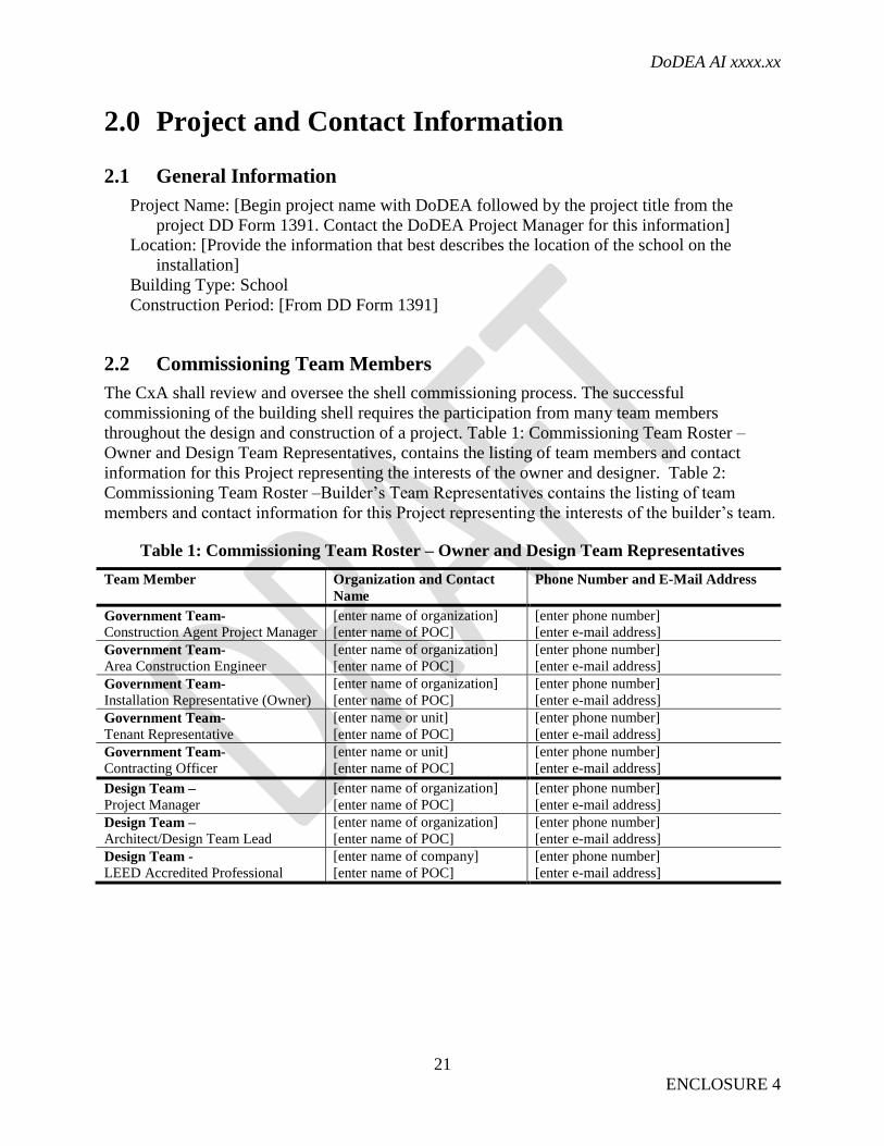
2.2 Commissioning Team Members
The CxA shall review and oversee the shell commissioning process. The successful
commissioning of the building shell requires the participation from many team members
throughout the design and construction of a project. Table 1: Commissioning Team Roster –
Owner and Design Team Representatives, contains the listing of team members and contact
information for this Project representing the interests of the owner and designer. Table 2:
Commissioning Team Roster –Builder’s Team Representatives contains the listing of team
members and contact information for this Project representing the interests of the builder’s team.
Table 1: Commissioning Team Roster – Owner and Design Team Representatives
Team Member Organization and Contact
Name
Phone Number and E-Mail Address
Government Team-
Construction Agent Project Manager
[enter name of organization]
[enter name of POC]
[enter phone number]
[enter e-mail address]
Government Team-
Area Construction Engineer
[enter name of organization]
[enter name of POC]
[enter phone number]
[enter e-mail address]
Government Team-
Installation Representative (Owner)
[enter name of organization]
[enter name of POC]
[enter phone number]
[enter e-mail address]
Government Team-
Tenant Representative
[enter name or unit]
[enter name of POC]
[enter phone number]
[enter e-mail address]
Government Team-
Contracting Officer
[enter name or unit]
[enter name of POC]
[enter phone number]
[enter e-mail address]
Design Team –
Project Manager
[enter name of organization]
[enter name of POC]
[enter phone number]
[enter e-mail address]
Design Team –
Architect/Design Team Lead
[enter name of organization]
[enter name of POC]
[enter phone number]
[enter e-mail address]
Design Team -
LEED Accredited Professional
[enter name of company]
[enter name of POC]
[enter phone number]
[enter e-mail address]
DoDEA AI xxxx.xx
22
ENCLOSURE 4
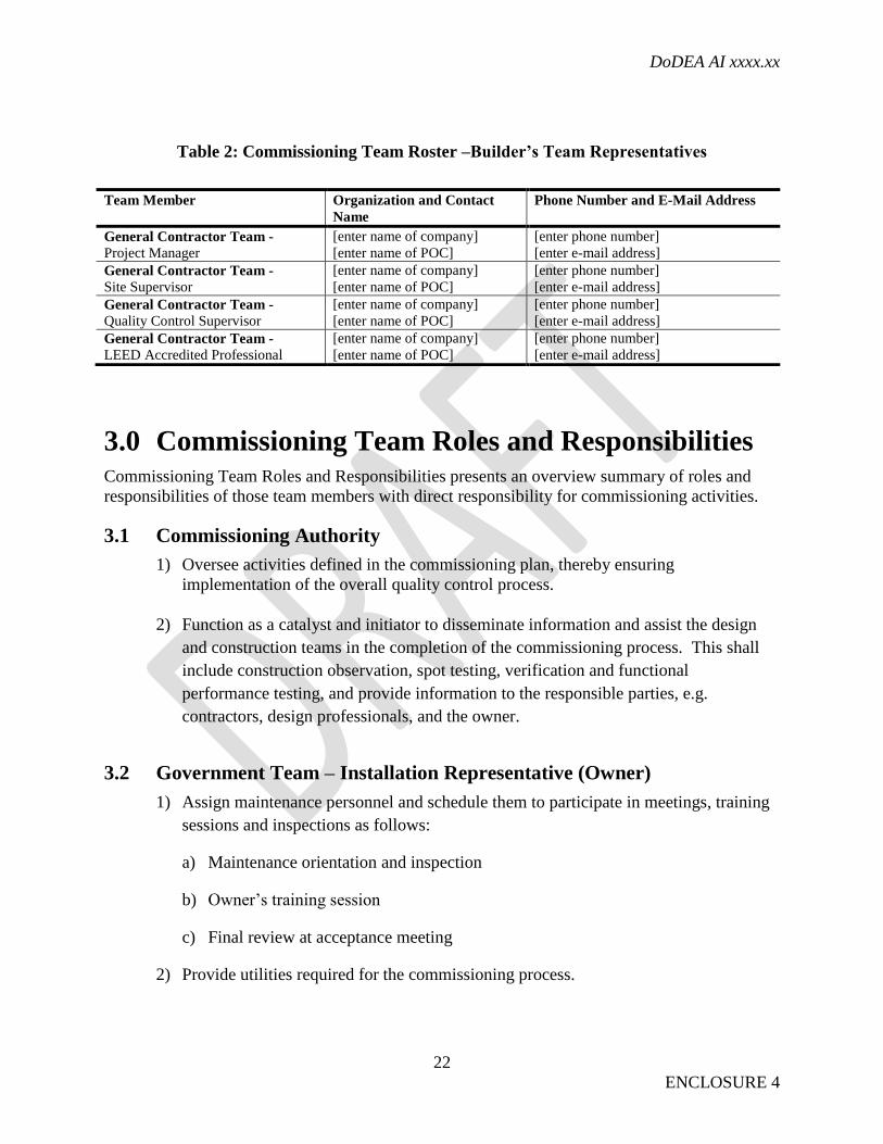
Table 2: Commissioning Team Roster –Builder’s Team Representatives
Team Member Organization and Contact
Name
Phone Number and E-Mail Address
General Contractor Team -
Project Manager
[enter name of company]
[enter name of POC]
[enter phone number]
[enter e-mail address]
General Contractor Team -
Site Supervisor
[enter name of company]
[enter name of POC]
[enter phone number]
[enter e-mail address]
General Contractor Team -
Quality Control Supervisor
[enter name of company]
[enter name of POC]
[enter phone number]
[enter e-mail address]
General Contractor Team -
LEED Accredited Professional
[enter name of company]
[enter name of POC]
[enter phone number]
[enter e-mail address]
3.0 Commissioning Team Roles and Responsibilities Commissioning Team Roles and Responsibilities presents an overview summary of roles and
responsibilities of those team members with direct responsibility for commissioning activities.
3.1 Commissioning Authority
1) Oversee activities defined in the commissioning plan, thereby ensuring
implementation of the overall quality control process.
2) Function as a catalyst and initiator to disseminate information and assist the design
and construction teams in the completion of the commissioning process. This shall
include construction observation, spot testing, verification and functional
performance testing, and provide information to the responsible parties, e.g.
contractors, design professionals, and the owner.
3.2 Government Team – Installation Representative (Owner)
1) Assign maintenance personnel and schedule them to participate in meetings, training
sessions and inspections as follows:
a) Maintenance orientation and inspection
b) Owner’s training session
c) Final review at acceptance meeting
2) Provide utilities required for the commissioning process.
DoDEA AI xxxx.xx
23
ENCLOSURE 4
3.3 Government Team – Construction Agent Project Manager
1) Provide shop drawing and submittal review to determine conformity with the
requirements and intent.
2) Review the developed testing documentation to ensure compliance with the design
requirements.
3) Provide analysis of test results in terms of compliance and non-compliance to contract
requirements.
4) Review and comment on the final commissioning report.
3.4 Design Team – Engineering Discipline Leads
1) Develop project specific design checklist for building shell commissioning.
2) Provide clarification and interpretation of the construction documents as it relates to
the building shell.
3) Specify project performance verification tests.
4) Advise on changes to construction contract and design intent that may impact on the
building shell upon request.
3.5 General Contractor Team – Quality Control Representatives
1) Develop project specific construction checklist for building shell commissioning.
2) Review the design documents for their affect on the commissioning process and the
final performance of the commissioned systems.
3) Be responsible for coordinating all of the efforts and be responsible for seeing that all
appropriate actions are taken to have the work performed in accordance with the
commissioning plan.
4) Participate in commissioning meetings.
5) Review as-built records as required by contract documentation and turn them over to
appropriate representatives of the contracting team.
1) Review all submittals.
2) Develop project specific component/field verification sheets.

DoDEA AI xxxx.xx
24
ENCLOSURE 4
3) Submit verification test data for review to the CxA and construction agent project
manager for review and acceptance.
4.0 Commissioning Deliverables
4.1 Key Commissioning Authority Deliverables
1) Review of Basis of Design and OPR.
2) Review of design documents and commissioning report.
3) Review Commissioning Plan.
4) Review building shell checklist forms.
4.2 Commissioning Report
A final Commissioning report by CxA team will be provided to Government. The report shall
include the following sections:
1) Executive summary
2) Evaluation of the operating condition of the facility
3) Deficiencies that were discovered and the measures taken to correct them
4) Uncorrected deficiencies that were accepted by the owner
5) Test sheets
6) Reports that documented all field commissioning activities as they progress.
7) Approved As-built drawings
8) Operations and Maintenance manuals
DoDEA AI xxxx.xx
25
ENCLOSURE 5
ENCLOSURE 5
DODEA LEED IMPLEMENTATION GUIDE
1. GENERAL GUIDANCE. The following is an outline of procedures to aid in the
implementation of LEED for DoDEA projects. It is not a complete list of all steps required to
achieve certification. Certification requires an integrated design and construction approach with
an emphasis on communication between stakeholders and documentation of LEED and project
requirements. LEED is used as a third party verification tool to track DoDEA’s achievement of
goals and objectives.
Although they are similar to LEED, Federal and DoD sustainable design mandates are separate
standalone requirements. Meeting the LEED requirements does not in itself constitute
compliance with federal and DoD sustainable design mandates. The A/E and construction
contractor shall first address compliance with these separate standalone federal and DoD
requirements and then select LEED credits that contribute to compliance.
2. IMPLEMENTATION.
a. DD Form 1391.
(1) Establish the project sustainability and performance goals and address budget
impacts.
(2) Develop the initial Owner’s Project Requirements (OPR) document using guidance
provided in Enclosure 6.
(3) Develop the initial LEED Project Checklist.
b. Parametric Design Charrette (Code 3) Report.
(1) OPR – Review and incorporate the OPR developed for the DD Form 1391. Refine
the OPR as necessary with formal endorsement from the Installation, the DoDEA Design Center,
SEEPM, and the AOPM.
(2) LEED Project Checklist - refine and/or validate the target sustainability credit goals
for the project as identified in the DD Form 1391 and update the LEED Project Checklist
accordingly.
(3) The CAPM will coordinate formal endorsement and filing of the endorsed LEED
Project Checklist and OPR. The updated LEED Project Checklist will be endorsed by the
Installation, the DoDEA Design Center, the SEEPM, the User and the AOPM.
c. RFP Development.
(1) Include completed OPR document and LEED Project Checklist.
DoDEA AI xxxx.xx
26
ENCLOSURE 5
(2) Indicate post-award LEED submittal and documentation requirements. Include and
require compliance with the applicable LEED-NC Submittals document. Include monthly
updates to the LEED documents.
(3) Require the A/E and construction contractor to provide a LEED AP assigned to the
project through closeout.
(4) Require a Technical proposal that includes the LEED Project Checklist indicating
proposed credits to be claimed.
(5) The CAPM will coordinate formal endorsement and filing of the endorsed LEED
Project Checklist and OPR. The LEED Project Checklist representing the project current rating
resulting from the conformed proposal will be endorsed by the Installation, the DoDEA Design
Center, the SEEPM, the A/E, and the AOPM.
d. Registration Procedure - Project registration occurs no later than 35% concept design by
the A/E. Projects should be registered before design commences so that the templates are
available to the design team from the start of design.
(1) Select the appropriate rating system for the project.
(2) Verify the project meets the LEED Minimum Project Requirements. If so select
YES, if not notify the SEEPM.
(3) Project Information Section:
(a) Project Title: Begin project name with DoDEA followed by the project title from
the project DD Form 1391. Contact the DoDEA Project Manager for this information.
(b) Address 1 and 2: Provide the information that best describes the location of the
school on the installation.
(c) City: Provide name of installation.
(d) County, State / Province, Country, Zip / Postal Code: Provide as known.
(e) School District: Select one of the following: DoDEA Americas, DoDEA Europe,
or DoDEA Pacific.
(f) Anticipated Construction Start and End Dates: From DD Form 1391.
(g) Gross Square Footage: Provide total building area from DD Form 1391. Exclude
area of any buildings that are exempt from the LEED achievement requirements.
(h) Is Project Confidential: Indicate NO except if project has security sensitivity.

DoDEA AI xxxx.xx
27
ENCLOSURE 5
(i) Notification of Local Chapter: NO.
(j) Anticipated Project Type: Provide as known.
(k) Anticipated Certification Level: Silver minimum.
(l) Project Owner POC: The DoDEA Sustainability and Energy Efficiency Program
Manager shall act as owner; contact the DoDEA Project Manager for this information.
(m) Owner Organization: DoDEA.
(n) Owner Type: Government use: Federal.
e. Design.
(1) Design Charrette. A conference will be held and the conference agenda will include
discussion of LEED roles and responsibilities, goals and compliance requirements, coordination
issues including assignment of LEED Online team memberships for the construction agent,
DoDEA Design Center, SEEPM and installation representatives for review purposes, discussion
of possible problem areas, and review of documentation requirements. Meeting attendees will
include CAPM, AOPM, DoDEA Design Center PM, SEEPM, User and Installation
Representative(s) including planning and maintenance staff, all designers of record, and the
design team, including LEED APs. For design/build projects include the construction team,
including the assigned project LEED APs.
(2) Design Documents. LEED credit requirements will be incorporated into drawings
and specifications, including all required construction phase documentation (as defined in LEED
Submittals document).
(3) LEED Supporting Documentation. Each design submittal will include the LEED
Project Checklist identifying all credits claimed. Final design submittal for each portion of the
work will include all required design documentation (as defined in LEED Submittals document)
for that portion of the work (example - all site credit design documentation with final site
design). All design documentation will be uploaded to LEED Online when final design is
submitted.
(4) The CAPM will coordinate formal endorsement and filing of the endorsed LEED
Project Checklist and OPR. The LEED Project Checklist representing the project current rating
resulting from the final design will be endorsed by the Installation, the DoDEA Design Center,
the SEEPM, the A/E and AOPM.
(5) Design Phase Certification - Projects will be required to submit a design application
to LEED online to establish the design score. Throughout the certification process the Designer
of Record shall be required to answer questions from the GBCI review team and must remain
available to support the certification process to achieve certification.

DoDEA AI xxxx.xx
28
ENCLOSURE 5
(6) Transfer to construction contractor. After the LEED Design Submittal has been
completed and the construction contract has been awarded, the A/E shall transfer LEED
administrative privileges to the construction contractor so that contractor can complete the
construction credit documentation and project certification.
f. Construction.
(1) Preconstruction Conference. A conference will be held and the conference agenda
will include discussion of roles and responsibilities, goals and compliance requirements,
coordination issues including assignment of LEED Online team memberships for the
construction agent and installation representatives for review purposes, discussion of possible
problem areas, and review of documentation requirements relating to LEED. Meeting attendees
will include designer of record, all project-assigned LEED APs, construction contractor, AOPM,
CAPM, SEEPM, construction staff and Installation Representative(s) including maintenance
personnel.
(2) LEED-Supporting Documentation. The construction contractor will update the
LEED Online documentation on at least a monthly basis. Monthly review of LEED
documentation by Construction Agent staff is required and progress payments will be
coordinated with this review. The Construction Agent staff, SEEPM and Installation will review
the LEED supporting documentation and may request additional audit documentation where
deemed necessary.
(3) Contractor Non-compliance. DoDEA’s options for non-compliance to influence the
construction contractor’s behavior include interim unsatisfactory performance evaluation,
withholding of progress payments and lastly, termination for default and re-procurement.
(4) Certification - Certification is applied for no later than the BOD. Financial closeout
of contracts that require certification cannot occur until certification ruling is obtained. GBCI
does not require that post-occupancy credit activities be complete at the time of certification
request but contract requirements must be completed prior to project financial closeout.
Throughout the certification process the construction contractor shall be required to answer
questions from the GBCI Review Team and must remain available to support the certification
process to achieve certification.
g. Government Validation. All projects produce LEED documentation as part of project
development and execution, using project funds. The CAPM is responsible for reviewing the
project documentation and validating that all credits are correctly interpreted and documented in
accordance with the LEED standard, from design through construction closeout. This is required
on all projects, including those that will be formally LEED certified by GBCI. DoDEA expects
the CAPM to review and validate LEED compliance as part of Design and Construction Agent
activities. The CAPM is responsible at all project phases for ensuring that Government
Validation by qualified individuals (LEED AP as well as appropriate engineering disciplines)
occurs. Validation of design credits is part of design independent technical review/conformance
review. Validation of construction credits is part of construction Supervision and Administration

DoDEA AI xxxx.xx
29
ENCLOSURE 5
(S&A) activities. Government Validation of projects may include audit of any or all credits
claimed and request for additional information at the SEEPM’s discretion. The Designer of
Record and construction contractor will compile all backup supporting data for all LEED credits
claimed but are not required to submit additional information unless requested.

DoDEA AI xxxx.xx
30
ENCLOSURE 6
ENCLOSURE 6
DODEA OWNER’S PROJECT REQUIREMENTS TEMPLATE
1. GENERAL GUIDANCE. The Owner’s Project Requirements (OPR) is a written document
that details the ideas, concepts and criteria that are determined by the owner to be important to
the success of the project. It provides the design team and commissioning authority (CxA) a
“road map” for the development of a successful design and enables them to verify the needs have
been addressed in the construction documents. The OPR shall be created by the AOPM for the
DD Form 1391. The OPR needs to be updated at each major design milestone and approved by
the [Installation/User/Government]. It shall be the responsibility of the CAPM to update the
document at the Parametric Design Charrette. It shall be included in the RFP. Upon selection of a
CxA, the CxA shall assume responsibility for implementing, refining, and augmenting the OPR
throughout design, construction, and the post occupancy period of one year following substantial
completion.
2. GENERAL PROJECT DESCRIPTION.
a. Purpose. The purpose of this project is to provide [new school facilities] to educate
[elementary/middle/high] school students. The facility will be approximately [00,000] square
feet in size and is designed to serve a student population of [000] students and a staffing
compliment of [00] instructors and [00] other staff members. This facility is intended to be a 21st
Century Education Facility.
b. History. This project is a [design/bid/build, design/build] delivery project consistent with design
standards, specifications and project delivery methods developed and executed for [DDESS/DoDDS-
Cuba/DoDDS-E/DoDDS-P/DoDDS-Guam] standard facilities. The DoDEA (Department of Defense
Education Activity) Design Center is the subject matter expert for the owner. The [USACE/NAVFAC]
[Regional] District is the construction agent for the owner.
c. Program. The [elementary/middle/high] school shall be designed to accommodate
students from [prekindergarten level through twelfth grade]. DoDEA Education Facilities
(EdSpecs) form the basis for planning and construction for the Department of Defense school
facilities and are applicable to this project.
d. Facility Schedule
(1) Typical school week hours of operation (M-F):
(2) Typical weekend hours of operation:
(3) After school activities and special events days and hours:
e. Restrictions and Limitations
DoDEA AI xxxx.xx
31
ENCLOSURE 6
(1) Installation restrictions (Installation Master Plan):
(2) Standoff distance:
(3) Utility issues:
(4) Easements, right of ways:
(5) Access limitation:
(6) Height restrictions:
f. Owner/User Project Requirements
(1) This project shall achieve a minimum Silver rating in accordance with US Green
Building Council’s LEED ® rating system.
(2) Owner Directives – the following are specific requests:
(a) Use [___ controls manufacturer to maintain existing system communication,
permeable paving]
(b) Do not use [carpet, furniture without GREENGUARD certification]
(3) Community Requirements – [schools to be designed for afterhours access to
gymnasium]
(4) Adaptability/expansion - [No future expansion is planned for this facility/Future
expansion is planned for this facility as follows:]
(5) Seismic
(6) Safety and Security
(7) Aesthetics- installation master plan considerations
(8) Access to Technology and Informational resources
(9) Specialty Areas
DoDEA AI xxxx.xx
32
ENCLOSURE 6
3. GOALS.
a. Improve the Learning Environment
(1) Lighting for Improved Learning
(a) Goal - Improve the learning and teaching performance through effective lighting
design.
(b) Benchmark – LEED IEQ Credit 8.1: Daylight and Views – Daylight, IEQ Credit
6.1: Controllability of Systems - Lighting
(2) Acoustics for Improved Learning
(a) Goal – Prevent poor acoustics from impacting the students’ ability to learn and
the teachers’ ability to teach
(b) Benchmark – LEED IEQ Credit 9: Enhanced Acoustical Performance
(3) Air Quality for Improved Learning
(a) Goal – Reduce absenteeism
(b) Benchmark - LEED IEQ Prerequisite 1: Minimum Indoor Air Quality
Performance, IEQ Credit 3.1: Construction Indoor Air Quality, IEQ Credit 4: Low Emitting
Materials, IEQ Credit 5: Indoor Chemical and Pollutant Source Control
(4) Thermal Comfort for Improved Learning
(a) Goal - Provide air temperature and relative humidity for a comfortable learning
environment so students and teachers can reach their full potential.
(b) Benchmark – LEED IEQ Credit 6.2: Controllability of Systems – Thermal
Comfort, IEQ Credit 7.1: Thermal Comfort - Design
c. Improve Facility Efficiency
(1) Optimize Energy Performance
(a) Goal - Reduce energy consumption to the highest level possible that is
economically viable without compromising the learning environment.
DoDEA AI xxxx.xx
33
ENCLOSURE 6
(b) Benchmark – LEED EA Credit 1: Optimize Energy Performance (15 points)
(2) Conserve Water
(a) Goal - Reduce water consumption to the highest level possible that is
economically viable without compromising the learning environment.
(b) Benchmark – LEED WE Credit 1: Water Efficient Landscaping, WE Credit 3:
Water Use Reduction
d. Reduce the Environmental Impact of Materials
(1) School Recycling Program
(a) Goal – Teach students the importance of resource conservation and environmental
stewardship.
(b) Benchmark – LEED MR Prerequisite 1: Storage and Collection of Recyclables
(2) Construction Recycling Program
(a) Goal – Divert a minimum of 50% construction debris from the waste stream
through recycling and salvage
(b) Benchmark – LEED MR Credit 2: Construction Waste Management
(3) Responsible Selection of Materials
(a) Goal – Use sustainably responsible material in the construction of facilities
(b) Benchmarks – LEED MR Credit 4: Recycled Content, MR Credit 6: Rapidly
Renewable Materials
(4) Reduce Ozone Depletion
(a) Goal – Zero use of CFC based refrigerants
(b) Benchmark – LEED EA Prerequisite 3: Enhanced Refrigerant Management
DoDEA AI xxxx.xx
34
ENCLOSURE 6
a. Monitor Results
(1) Commissioning
a. Goal – Verify the building systems are installed, calibrated and perform as
intended
b. Benchmark – LEED EA Credit 3: Enhanced Commissioning
(2) Metering
(a) Goal – Provide accurate useful energy consumption data in a user friendly format
(b) Benchmark – Provide metering at the whole building level and sub metering for a
minimum of HVAC, hot water, elevator, and kitchen. Use FEMP Metering Best Practices,
Release 2.0 for guidance.
(3) Survey Users
(a) Goal - Provide superior customer service to students and teachers.
(b) Benchmark – IEQ Credit 7.2: Thermal Comfort Verification
5. SYSTEMS CRITERIA.
a. Building Systems Life Cycle Requirements - The school shall have a 25-year useful
design life before a possible re-use/re-purpose or renovation requirement, to include normal
sustainment, restoration, modernization activities and a 50-year building replacement life. The
design and construction shall provide an appropriate level of quality to ensure continued use of
the facility over that time period with the application of reasonable preventative maintenance and
repairs that would be industry-acceptable to major civilian sector schools.
b. Site Infrastructure Life Cycle Requirements - The site infrastructure will have at least a
45-year life expectancy with industry-accepted maintenance and repair cycles.
At a minimum, all equipment shall meet or exceed the minimum efficiencies as established by
ASHRAE 90.1 - SI. The contractor shall purchase Energy Star or FEMP designated products.
The term "Energy Star product” means a product is rated for energy efficiency under an Energy
Star program. The term "FEMP designated product” means a product that is designated under the
Federal Energy Management Program of the Department of Energy as being among the highest
25 percent of equivalent products for energy efficiency. In the case of an electric motor of 1 to
500 horsepower the Contractor shall select only a premium efficient motor.

DoDEA AI xxxx.xx
35
ENCLOSURE 6
c. Maintainability Expectations
d. System Integration

DoDEA AI xxxx.xx
36
ENCLOSURE 6
GLOSSARY
PART I. ABBREVIATIONS AND ACRONYMS
ACRONYM
A/E
ANSI
AOPM
ASHRAE
BOD
CAPM
CFC
CSI
Cx
CxA
DDESS
DoDDS
DoDEA
EPA
FC
GBCI
HVAC
IAQ
LCCA
LEED
architect/engineer
American National Standards Institute
DoDEA Area Office Project Manager
American Society of Heating, Refrigerating and Air-Conditioning
Engineers
beneficial occupancy date
construction agent project manager
chlorofluorocarbon
Construction Specifications Institute
commissioning
commissioning authority
Domestic Dependent Elementary and Secondary Schools
Department of Defense Dependents Schools
Department of Defense Education Activity
Environmental Protection Agency
footcandles
Green Building Certification Institute
heating, ventilation, and air conditioning
indoor air quality
life cycle cost analysis
Leadership in Energy and Environmental Design
DoDEA AI xxxx.xx
37
ENCLOSURE 6
MERV
MILCON
NIBS
O&M
OCONUS
OPR
SEEPM
SMACNA
SRM
STC
USDA
minimum efficiency reporting value
military construction
National Institute of Building Sciences
operations and maintenance
outside the continental U.S.
owner’s project requirements
sustainability and energy efficiency program manager
Sheet Metal and Air Conditioning National Contractors Association
sustainment, restoration and modernization
Sound Transmission Class
U.S. Department of Agriculture

SPEC
IALS
YSTEM
SDES
IGNGUIDE
PHASE[1]
V.1.0J
AN[2012
]

i V1.0JAN[2012]INTRODUCTION
INTRODUCTION
DEPARTMENT OF DEFENSE EDUCATION ACTIVITY
DOMESTIC DEPENDENT ELEMENTARY AND SECONDARY SCHOOLS (DDESS)
US ARMY CORPS OF ENGINEERS
NORFOLK DISTRICT
DODEA DESIGN CENTER
GUIDE DEVELOPMENT FIRMS
PARKHILL SMITH & COOPER, INC.
NSYNC SERVICES, INC.
FANNING, FANNING & ASSOCIATES
CONTRIBUTORS
MICHAEL CHANEY, DDESS, CHIEF, FACILITIES ENGINEERING BRANCH
LENNY DOBSON, DDESS, CHEIF, INFRASTRUCTURE SYSTEMS BRANCH
PAT COVINGTON, DDESS, FACILITIES MAINTENANCE MANAGER
ROBERT ROLLO, PSC, FIRM PRINCIPAL
TROY SWINNEY, PSC, FIRM PRINCIPAL
CHRIS POWITZKY, ASSOC. AIA
RANDALL STEWART, RCDD, NSYNC, DIRECTOR OF OPERATIONS
JOHN FANNING, FFA, FIRM PRINCIPAL
SCOTT FANNING, FFA, FIRM PRINCIPAL
MARCUS KESLIN, FFA, CONSULTANT
ABOUT THIS GUIDE
THIS DESIGN GUIDE HAS BEEN PREPARED TO PROVIDE THE A/E COMMUNITY WITH THE NECESSARY CRITERIA TO ASSIST IN THE
DESIGN OF THE SPECIAL SYSTEMS THAT ARE TYPICALLY FOUND IN AN EDUCATIONAL FACILITY. WHILE CERTAIN FEATURES OF THE
SYSTEM DESIGN WILL VARY FROM PROJECT TO PROJECT, THE REQUIREMENTS REFLECTED IN THIS GUIDE ARE INTENDED TO PROVIDE
THE MINIMUM REQUIREMENTS REQUIRED BY DODEA/DDESS. THIS DOCUMENT REPRESENTS PHASE[1] OF THE DESIGN GUIDE
DELIVERABLES. PHASE[2] WILL ACCOMPANY THIS DOCUMENT AND WILL INCLUDE STANDARDS FOR ADDITIONAL SPECIAL SYSTEMS.

V1.0JAN[2012]ii TABLE OF CONTENTS
[1] DATA/TELECOMMUNICATION SYSTEM
[1.1] SUMMARY
[1.1.A] OUTSIDE CABLE PLANT
[1.2] SYSTEM REQUIREMENTS
[1.2.A] MAIN TELECOMMUNICATION ROOM (TR1)
[1.2.B] ADDITIONAL TELECOMMUNICATION ROOM (TR2)
[1.2.C] VIDEO DISTRIBUTION
[1.2.D] WIRELESS CONNECTIVITY
[1.2.E] TELEPHONE SYSTEMS
[1.2.F] EQUIPMENT RACKS
[1.2.G] PATCH PANELS
[1.2.H] CAT 6 COPPER CABLES
[1.2.I] FIBER OPTIC CABLES
[1.2.J] PATCH CORDS
[1.2.K] CABLE PATHWAYS
[1.2.L] CABLE TRAYS
[1.2.M] CONDUITS
[1.2.N] OPEN CABLES
[1.2.O] WORK AREA OUTLETS
[1.2.P] TESTING - CAT 6 CABLES
[1.2.Q] TESTING - FIBER OPTIC CABLES
[1.3] DOCUMENTATION REQUIREMENTS
[1.3.A] ZONE MAP
[1.3.B] NEIGHBORHOOD PLAN
[1.3.C] EQUIPMENT SCHEDULES
1
2
3
3
4
6
6
6
6
7
7
8
8
8
9
10
10
11
11
11
TABLE OF CONTENTS

1 V1.0JAN[2012]PHASE[1]
[1] DATA/TELECOMMUNICATION SYSTEMS
[1.1] SUMMARY
This chapter describes the Data/Telecommunication system design and installation/testing requirements.
The design requirements are intended to provide uniformity between design firms of symbols, equipment layouts, cabling methods, pathways, drawing submittal requirements, and specification requirements.
Every facility shall have wired and wireless data system installed and tested by a qualified firm experienced in network installations. All designs shall be in accordance with Building Industry Consulting Service International (BICSI). The network system shall be designed by a Registered Communication Distribution Designer (RCDD) and installed in accordance with the Telecommunications Industry Association (TIA) and Electronic Industry Alliance (EIA) General Guidelines, and the National Electrical Code (NEC). The design professional shall include in the design analysis of all projects a list of active components and a pull schedule as indicated in this guide to be furnished to appropriate DDESS staff to facilitate planning. These guidelines will be coordinated with the Education Specifications (EdSpecs) and will be a supplement. This active equipment shall be furnished and installed by the Government, however, the schedule shall be developed by the design team. Government furnished and installed equipment is noted in the Design Guide.
The following list indicates the minimum requirements for deliverables to be included in the construction drawings. These are representative examples. (Refer to 1.3 DOCUMENTATION REQUIREMENTS):
[1] Zone Map[2] Neighborhood Plan[3] Equipment Schedules
The system shall consist of the following:
[1] Incoming fiber optic and copper cables from the community telecommunication demarcation building to the Main Telecommunications Room 1 (TR1) [2] TR1 housing the main network equipment rack
[3] Additional telecommunication rooms (TR2, TR3, etc.) housing network distribution equipment racks as needed
[4] Fiber optic and copper distribution cables from TR1 to each additional telecommunication room
[5] Cable trays, conduits, and supporting devices for fiber optic and copper work area cables
[6] CAT 6 copper cables from the distribution rack patch panels to individual work area outlets
[7] Work area outlets consisting of work area connectors, faceplates, room identification, patch panel, and port serving each connector
PHASE[1]1Standards:
The design and installation of the network shall comply with the following Standards unless modified by this document:
• ANSI/TIA/EIA-568-B, Commercial Building Telecommunications Cabling Standard
• ANSI/TIA/EIA-569-A, Commercial Building Standards for Telecommunications Pathways and Spaces
• ANSI/TIA/EIA-569-B, Commercial Building Standard for telecommunications Pathways and Spaces
• ANSI/TIA/EIA-606, Administration Standard for the Telecommunications Infrastructure of Commercial Buildings
• ANSI/TIA/EIA-607, Commercial Building Grounding and Bonding Requirements for Telecommunications
• ANSI/TIA/EIA 526-7, Measurement of Optical Power Loss of Installed Single-Mode Fiber Cable Plant
• ANSI/TIA/EIA 526-14, Optical Power Loss Measurements of Installed Multimode Fiber Cable Plant
• NFPA 70, National Electrical Code• NFPA 101, Life Safety Code• ANSI/IEEE C2-2007, National Electrical Safety Code• ANSI-J-STD-607-A-2002, Commercial Building
Grounding (Earthing) and Bonding Requirements for Telecommunications
• ANSI/NECA/BICSI 568-2006, Standard for Installing Commercial Building Telecommunication Cabling
• TIA Technical CommitteeTR-42, Technical Service Bulletin 162, Telecommunications Cabling Guidelines for Wireless Access Points
• 13A - For Outside Plant Cables (OSP)
(A) Outside Plant Cables (OSP):
At the onset of the project, the telecommunications design team must communicate with installation community responsible for the telecommunication facilities, network infrastructure and distribution system. In particular, this discussion shall identify the location and capacity of the existing available fiber optic and copper cables in the proximity of the project. The design intent is to provide a dedicated 12 strands of single mode fiber optic cable and a 50 pair copper cable from the installation’s demarcation point to the new school. The connection points and routing path shall be clearly identified in the facility construction documents. All OSP cables and raceways shall be compliant with Installation Information Infrastructure Architecture (I3A).
The construction documents to be prepared by the A/E shall include detail drawings of all the requirements, governed by the military community telecommunication standards, for the OSP. These shall include but, are not limited to, the number and type of conduits, cable vaults, pedestals, any innerduct, maintenance holes, minimum burial depths and details that depict how the OSP shall enter into the building.
The OSP, including both fiber and copper cables, will enter underground into the main telecommunication room, Telecommunications Room 1 (TR1). Refer to the TR1 floor plan drawing [Diagram 1] for the configuration of the room and cable entrance locations.

V1.0JAN[2012]2 PHASE[1]
The incoming copper cables will be terminated in a protected entrance terminal (PET) enclosure and routed in cable tray to 110 type punch down blocks located on the telephone backboard wall as indicated. The copper cables will be routed in overhead ladder trays to the equipment racks located in TR1.
[1.2] SYSTEM REQUIREMENTS
(A) Main Telecommunication Room (TR1):
The A/E shall provide detailed plan drawings of TR spaces that indicate proposed layout interconnections and key clearances. Each facility shall contain one main TR1 for network equipment. The main telecommunications room shall meet the following requirements:
[1] The room shall be a minimum of approximately 160 SF with dimensions in each orientation of 10’ x 16’ with a 9’ minimum ceiling height. The room shall have one door, minimum of 36” wide. The door shall have a key-pad lock to control access. The room shall have no windows. All walls shall be covered with 4’ x 8’ x 3/4” painted, plywood from 6” AFF. The plywood shall be mounted in a vertical position, adjoined to minimize seams, contain not knots, and have “A” grade exposed face. The A/E shall determine if fire-retardant-treated (FRT) plywood is required for compliance with applicable building codes. Refer to Diagrams 2-6 for additional information.
[2] In order to mitigate the potential conflict of electromagnetic interference (EMI), TR1 shall not be located adjacent to any electrical room and the racks within TR1 shall maintain a minimum separation of 4’ from any electrical equipment.
[3] The room shall have a dedicated cooling system independent from the mechanical system serving the rest of the building. This room shall have its own thermostat. The room shall be provided with positive pressure to minimize dust intrusion. The size of the cooling system shall be determined by the heat load produced by the communications equipment. Designer shall provide heat load estimates based on equipment systems that will be installed in the TR1 to support building systems.
[4] Any equipment unrelated to TR1 shall not be installed in or routed through this room.
[5] This room shall be dedicated to systems described herein.
[6] The room shall contain a minimum of four, two-post equipment racks, secured at the top and bottom, with planned expansion of at least one rack. Refer to Diagrams 1-6 for additional information.
[7] TR1 shall have a standard telephone communication system.
[8] Rack-1 shall be dedicated to horizontal data cabling for data drops located in the proximity of TR1. Switches and patch panels as described below shall be installed in Rack-1 to a maximum of 240 cables. Refer to Diagram 6 for additional information.
[9] Rack-2 shall be used for termination of all voice and wireless distribution cabling. Refer to Diagram 6 for additional information.
[10] Rack-3 shall be used to support video distribution/CATV and any requirements for public address intercom and clock systems. Refer to Diagram 6 for additional information.
[11] Rack-4 shall contain the fiber optic termination and distribution equipment in the top-most part of the rack. The site incoming fiber shall terminate in this rack. The outgoing fiber to each additional Telecommunication Room and/or adjacent racks shall originate in the top of this rack. Refer to Diagram 6 for additional information.
[12] The rack configuration for TR1 shall include physical parameters to mount a fifth rack to accommodate any future expansion. All racks shall have a minimum clearance of 3’-0” from any face of the equipment, including sides of end racks, to any wall or wall-mounted equipment.
[13] Provide a telecommunication master ground bar (TMGB) in TR1 for grounding the equipment racks and cable trays. The bar shall be a minimum of 12” long, 1/4” thick copper and attached to the wall with two insulators at 7’-0” AFF. The TMGB shall be connected to the electrical system main grounding electrode with a conductor sized in accordance with ANSI-607. The electrode grounding system shall be designed to provide a maximum resistance to earth of 5 ohms or less.
[14] TR1 shall be illuminated to an average of 50 foot-candles at 36” AFF using fluorescent luminaires located in front and rear of the racks to avoid shadows on the primary rack surface planes.
[15] The A/E shall install 20A, 120V duplex receptacles on the perimeter walls at approximately 6’ O.C. Provide receptacles along the perimeter of the rooms 6’-0” OC and circuit every three receptacles to a dedicated circuit. The quantity of receptacles per circuit shall not exceed three. In addition, provide a dedicated 20A, 120 volt circuit that terminates in a twistlock receptacle mounted on the top or bottom of each rack for connection to remotely manageable power distribution units (PDUs) with ammeter mounted within the racks (one per rack).
[16] PDU Management: The power distribution units at each of the racks shall incorporate switching technology to provide a manageable system for remote control, alarms, current monitoring and power delays. The system shall be Web based and will allow the user to access, configure and manage the units from remote locations.
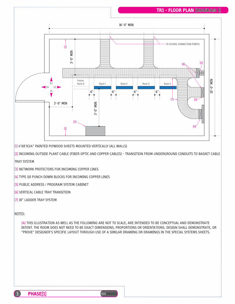
[1] 4’X8’X3/4” PAINTED PLYWOOD SHEETS MOUNTED VERTICALLY FLOOR TO CEILING - TYPICAL FOR ALL WALLS
[2] INCOMING OUTSIDE PLANT CABLE (FIBER OPTIC CABLE) - TRANSITION FROM UNDERGROUND CONDUITS TO BASKET CABLE TRAY SYSTEM
[3] NETWORK PROTECTORS FOR INCOMING COPPER LINES
[4] TYPE 110 PUNCH DOWN BLOCKS FOR TERMINATION OF COPPER LINES
[5] PUBLIC ADDRESS/PROGRAM SYSTEM CABINET
[6] VERTICAL CABLE TRAY TRANSITION
TR1 FLOOR PLAN
10'-
0" M
IN
3'-0
" M
IN
3'-0
" M
IN3'-0" MIN
16'-0" MIN
6"6" 6" 6"
[1]
[1]
[5]
[4]
[7] [3]
[6] [2]
Rack-1 Rack-2 Rack-3
TO SCHOOL CONNECTION POINTS
Rack-4FutureRack-0
E1
E2
E3E4
[1] 4’X8’X3/4” PAINTED PLYWOOD SHEETS MOUNTED VERTICALLY (ALL WALLS)
[2] INCOMING OUTSIDE PLANT CABLE (FIBER OPTIC AND COPPER CABLES) - TRANSITION FROM UNDERGROUND CONDUITS TO BASKET CABLE
TRAY SYSTEM
[3] NETWORK PROTECTORS FOR INCOMING COPPER LINES
[4] TYPE 110 PUNCH DOWN BLOCKS FOR INCOMING COPPER LINES
[5] PUBLIC ADDRESS / PROGRAM SYSTEM CABINET
[6] VERTICAL CABLE TRAY TRANSITION
[7] 18” LADDER TRAY SYSTEM
NOTES:
(A) THIS ILLUSTRATION AS WELL AS THE FOLLOWING ARE NOT TO SCALE, ARE INTENDED TO BE CONCEPTUAL AND DEMONSTRATE INTENT. THE ROOM DOES NOT NEED TO BE EXACT DIMENSIONS, PROPORTIONS OR ORIENTATIONS. DESIGN SHALL DEMONSTRATE, OR “PROVE” DESIGNER’S SPECIFIC LAYOUT THROUGH USE OF A SIMILAR DRAWING OR DRAWINGS IN THE SPECIAL SYSTEMS SHEETS.
3 V1.0JAN[2012]PHASE[1]
TR1 - FLOOR PLAN (DIAGRAM 1)

TR1 ELEVATION [E1]
[1] PUBLIC ADDRESS/PROGRAM SYSTEM CABINET
[2] 4’X8’X3/4” PAINTED PLYWOOD SHEETS MOUNTED VERTICALLY FLOOR TO CEILING - TYPICAL FOR ALL WALLS
6"
[2]
[1]
[3]
PLYWOOD EDGE SHALLTERMINATE 6” AFF
[1] PUBLIC ADDRESS / PROGRAM SYSTEM CABINET
[2] 4’X8’X3/4” PAINTED PLYWOOD SHEETS MOUNTED VERTICALLY - TYPICAL FOR ALL WALLS
[3] DRYWALL EXTENDS TO STRUCTURE BEYOND 9’-0” AFF
[4] COORDINATE PLACEMENTS OF RECEPTACLES WITH PLYWOOD
V1.0JAN[2012]4 PHASE[1]
TR1 - ELEVATION [E1] [DIAGRAM 2]

5 V1.0JAN[2012]PHASE[1]
[17] Power Panel: In TR1, provide a 100 amp, 120/208 volt, three phase power panelboard located on the wall of the TR1 to provide easy access to the power circuit so that they can be de-energized and such that available power is in the room to accommodate any additional circuits that may be needed in the future.
(B) Additional Telecommunication Rooms (TR2, TR3, etc.):
Additional Telecommunication Rooms (TR2, TR3, etc.) shall be located where required to limit the total length of the CAT6 copper cable from the patch panel, to the furthest outlet to 275’ or less as measured through the cable tray pathways and in-room routing to include vertical rises and drops. The 275’ limit provides for sag and unexpected downturns of pathway as well as patch cables at the wall end outlets. Each level of a multi-story facility will contain a minimum of one TR. These telecommunication room(s) shall meet the same requirements as TR1 except as indicated by the following requirements:
[1] The room shall be a minimum size of 10’ x 10’ with a 9’ minimum ceiling height. The room shall have one door, minimum of 36” wide. The door shall have a key-pad lock to control access. The room shall have no windows if located on exterior walls. All walls shall be covered with 4’ x 8’ x 3/4” painted, plywood from 6” AFF. The plywood shall be mounted in a vertical position, adjoined to minimize seams, contain not knots, and have “A” grade exposed face. The A/E shall determine if fire-retardant-treated (FRT) plywood is required for compliance with applicable building codes.
[2] This room shall be dedicated to LAN equipment. This TR shall be used to distribute or terminate fiber optic and copper cables to any location other than TR1. Refer to Diagram 7 for additional information.
[3] The room shall contain at least one free-standing equipment rack, secured at the top and bottom, and associated cable management system. The room layout should indicate planned space for a future rack.
[4] The incoming fiber optic cable from the TR1 room shall terminate in the upper-most part of the rack.
[5] CAT6 patch panels for the horizontal cables shall be located below the fiber optic patch panel leaving a minimum of 4U space between FOPP and the first CAT6 patch panel. This allows space for the enclosed cable management system.
[6] Install additional racks (and cable management system) as needed for the quantity of horizontal cables to be terminated.
[7] Provide space in the data racks for the active equipment that will be furnished and installed by DDESS.
[8] The rack configuration for TR2, TR3, etc, shall include physical parameters to mount an additional rack to accommodate any future expansion. All racks shall have a minimum clearance of 3’-0” from the face of the equipment, including sides of end racks, to any wall or wall-mounted equipment. Refer to Diagram 7 for additional information.
(C) Video Distribution:
[1] As noted above, the video distribution shall originate in Rack-2 located in TR1 and will be routed through the respective secondary TR if needed.
[2] The video distribution in the teaching spaces is preferred to be provided through the Interactive White Board (IWB). Each IWB shall have a cart-mounted unit that connects to the wall outlet through via an attachment umbilical with strain relief provided. Refer to Diagram 8 for additional information.
[3] The IWB cart assembly will connect to a wall outlet that has a network connection to the TR and three additional CAT 6 cables that extend to the wall mounted IWB/projector.
[4] The location of the IWB’s shall be coordinated with the entire design team and user group to ensure that it is located in the optimum locations. IWBs may also be portable and connected with an umbilical.
(D) Wireless Connectivity:
[1] The A/E shall designate the location of the wireless access point outlets to provide full and optimal coverage relative to the actual design conditions of the project, including room layout, heights, and building materials utilized. The density of the wireless usage is expected to increase over time. The quantity and location of the wireless data points, included in the original design, shall be based on the total student population and shall assume laptop operation by every student and staff member. Each instructional area of the learning environment may have up to 120 students and/or wireless network devices. All wireless devices will be powered-over-ethernet (POE).
[2] Each primary teaching space shall have a minimum of one ceiling mounted wireless access point outlet.
[3] The wireless shall be powered-over-ethernet (POE) and be centrally located for optimal coverage. Facility mapping of wireless zones coverage and capacity must be considered.

TR1 ELEVATION [E2]
[1] 4’X8’X3/4” PAINTED F.R.T. PLYWOOD SHEETS MOUNTED VERTICALLY - TYPICAL FOR ALL WALLS
[2] OVERHEAD LADDER TRAY FOR COPPER CABLES
6"
7’-0
"
RACK 1 RACK 2 RACK 3 RACK 4
[1][2]
[3]
PLYWOOD EDGESHALL TEMRINATE6” AFF
LIGHTS
[1] 4’X8’X3/4” PAINTED PLYWOOD SHEETS MOUNTED VERTICALLY - TYPICAL FOR ALL WALLS
[2] OVERHEAD LADDER TRAY FOR COPPER CABLES
[3] DRYWALL EXTENDS TO STRUCTURE BEYOND 9’-0” AFF
V1.0JAN[2012]6 PHASE[1]
TR1 - ELEVATION [E2] [DIAGRAM 3]

7 V1.0JAN[2012]PHASE[1]
(E) Telephone Systems:
[1] The telephone system requirements shall be coordinated with the military community telecommunications authority to ensure that all new equipment is compatible. The intent is to design a voice system that is compatible for use with VoIP systems where available. All cabling, routing and limitations as indicated in this Design Guide also apply to the voice cabling.
[2] Telephone handsets shall be distributed throughout the building for use by teaching and Administration staff.
(F) Equipment Racks:
Equipment racks shall meet the following requirements:
[1] Equipment racks shall be free-standing standard EIA 19”racks with 84” overall height secured at the top and bottom (45 units). Racks shall be furnished with 6” vertical cable management system mounted on both sides of each rack or between adjacent racks. Racks shall contain the cable patch panels, neat-patch organizers, switches, fiber optic patch panels and other Government-furnished equipment.
[2] A minimum allocation of 25% spare capacity shall be included in the bottom most part of all racks as illustrated in Diagram 6, the TR1 rack elevation. The racks shall be subsequently populated with the data cabling beginning from the top left of the rack and ending near the bottom right of the rack, followed by the indicated 25% spare capacity below. Additional patch panels shall be installed in the rack to achieve the number of spare ports needed to achieve 25% spare allocation.
[3] Position the racks near the center of the room to ensure full perimeter access. Refer to Diagram 3.
[4] Provide rack elevation drawings for TR1 and for each TR room. The elevation shall clearly show the number and configuration of each rack. Detailed information including the number of switches, patch panels neat panels, wire management, and PDU’s shall be included in the drawings. The number of terminated cables and the total number of available ports shall be illustrated. Refer to Diagrams 6-7 for additional information.
[5] Plan TR spaces for an additional future rack location. Refer to Diagrams 6-7 for additional information.
(G) Patch Panels:
Patch panels shall be 48-port CAT 6.
[1] Each port shall be sequentially numbered from left to right 1 through 24 on top and 25 through 48 on the bottom. Install a Neat Patch (2U) horizontal wire manager below the 24-port (single-unit, single-row) or below the 48-port (double-unit, double-row) panels then leave a 2U open space below for customer provided switches. Triple-row panels are not allowed. Below the switch, install an additional Neat Patch (2U) horizontal wire manager. Repeat this step for the quantity of patch panels provided Refer to Diagrams 6-7 for additional information.
[2] Terminate cables by color and function using T568B configuration in the following order:
• Blue - Data leaving a minimum of 10% of open ports for future use
• Red - Video Distribution leaving 4-6 open ports for future use
• Orange - Wireless leaving 4-6 ports open for future use
• Yellow - Voice leaving 10% open ports for future use• Green - Network printing devices leaving 4-6 open
ports for future use and will utilize a standard work area outlet.
(H) CAT 6 Copper Cables:
[1] Cables shall be CAT 6, UTP. The outer jacket shall be:
• BLUE for Data• RED for Video• ORANGE for Wireless• YELLOW for Voice• GREEN for Network Printing Device
[2] No horizontal cable shall exceed 275 feet in length. In addition, any horizontal cable length in excess of 250 feet shall be specifically identified in the design documents. The telecommunications designer shall evaluate each cable run along its intended path of travel, including elevation changes, to verify the length restrictions are in compliance. All cables shall have passed the UL LAN certification program and be labeled with the UL marking. In above ceiling applications, utilize plenum-rated cable for air plenums.
[3] Cables shall not be installed within 12” of luminaires, motors, or other sources of interference.
[4] Splices within cable runs are not allowed. Cables in horizontal runs shall be bundled together neatly and untangled with hook-and-loop Velcro fastener straps. The installer must adhere to the manufacturer’s requirements for bend radius and pulling tensions for all CAT6 runs.
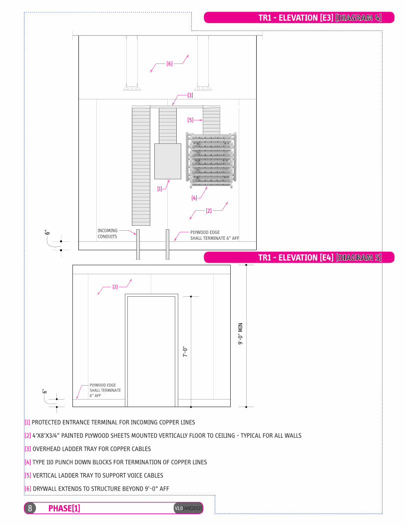
TR1 ELEVATION [E4]
[2] 4’X8’X3/4” PAINTED F.R.T. PLYWOOD SHEETS MOUNTED VERTICALLY FLOOR TO CEILING - TYPICAL FOR ALL WALLS
7'-0
"
6"
9'-0
" M
IN
[2]
PLYWOOD EDGESHALL TERMINATE6” AFF
TR1 ELEVATION [E3]
[1] NETWORK PROTECTORS FOR INCOMING COPPER LINES
[2] 4’X8’X3/4” PAINTED F.R.T. PLYWOOD SHEETS MOUNTED VERTICALLY FLOOR TO CEILING - TYPICAL FOR ALL WALLS
[3] OVERHEAD CABLE TRAY FOR COPPER CABLES
[4] TYPE 110 PUNCH DOWN BLOCKS FOR TERMINATION OF COPPER LINES
[5] VERTICAL CABLE TRAY TO SUPPORT VOICE CABLES
6"
[3]
[1]
[4]
[2]
[6]
[5]
PLYWOOD EDGESHALL TERMINATE 6” AFF
INCOMINGCONDUITS
[1] PROTECTED ENTRANCE TERMINAL FOR INCOMING COPPER LINES
[2] 4’X8’X3/4” PAINTED PLYWOOD SHEETS MOUNTED VERTICALLY FLOOR TO CEILING - TYPICAL FOR ALL WALLS
[3] OVERHEAD LADDER TRAY FOR COPPER CABLES
[4] TYPE 110 PUNCH DOWN BLOCKS FOR TERMINATION OF COPPER LINES
[5] VERTICAL LADDER TRAY TO SUPPORT VOICE CABLES
[6] DRYWALL EXTENDS TO STRUCTURE BEYOND 9’-0” AFF
V1.0JAN[2012]8 PHASE[1]
TR1 - ELEVATION [E3] [DIAGRAM 4]
TR1 - ELEVATION [E4] [DIAGRAM 5]

MODE
STACK
SPEE
DDUPL
XSTAT
MASTR
RPS
SYST
Cat
alys
t 375
0S
ER
IES
12
34
56
78
910
1X 2X
15X
16X
1112
1314
1516
1718
1920
2122
2324
2526
17X
18X
31X
32X
2728
2930
3132
3334
3536
3738
3940
4142
33X
34X
47X
48X
4344
4546
4748
24
13
NE
AT-
PA
TCH
NE
AT-
PA
TCH
NE
AT-
PA
TCH
NE
AT-
PA
TCH
NE
AT-
PA
TCH
MODE
STACK
SPEE
DDUPL
XSTAT
MASTR
RPS
SYST
Cat
alys
t 375
0S
ER
IES
12
34
56
78
910
1X 2X
15X
16X
1112
1314
1516
1718
1920
2122
2324
2526
17X
18X
31X
32X
2728
2930
3132
3334
3536
3738
3940
4142
33X
34X
47X
48X
4344
4546
4748
24
13
NE
AT-
PA
TCH
NE
AT-
PA
TCH
MODE
STACK
SPEE
DDUPL
XSTAT
MASTR
RPS
SYST
Cat
alys
t 375
0S
ER
IES
12
34
56
78
910
1X 2X
15X
16X
1112
1314
1516
1718
1920
2122
2324
2526
17X
18X
31X
32X
2728
2930
3132
3334
3536
3738
3940
4142
33X
34X
47X
48X
4344
4546
4748
24
13
A B C D E
TR1-
Rac
kEl
evat
ion
MODE
STACK
SPEE
DDUPL
XSTAT
MASTR
RPS
SYST
Cat
alys
t 375
0S
ER
IES
12
34
56
78
910
1X 2X
15X
16X
1112
1314
1516
1718
1920
2122
2324
2526
17X
18X
31X
32X
2728
2930
3132
3334
3536
3738
3940
4142
33X
34X
47X
48X
4344
4546
4748
24
13
NE
AT-
PA
TCH
NE
AT-
PA
TCH
E
1 2 3 4 5
FAN
STA
TUS
6
Cat
alys
t45
06
INP
UT
OK
FAN
OK
OU
TPU
T FA
IL
1000
AC
INP
UT
100-
240
V~
12-5
A50
/60
Hz
Sw
itch
mus
t be
in o
ff "O
" pos
ition
to In
stal
l/Rem
ove
pow
er s
uppl
y.Fa
sten
er m
ust b
e fu
lly e
nage
d pr
ior t
o op
erat
ing
pow
er s
uppl
y.
INP
UT
OK
FAN
OK
OU
TPU
T FA
IL
1000
AC
INP
UT
100-
240
V~
12-5
A50
/60
Hz
Sw
itch
mus
t be
in o
ff "O
" pos
ition
to In
stal
l/Rem
ove
pow
er s
uppl
y.Fa
sten
er m
ust b
e fu
lly e
nage
d pr
ior t
o op
erat
ing
pow
er s
uppl
y.
NE
AT-
PA
TCH
6" V E R T I C A L W I R E M A N A G E R
6" V E R T I C A L W I R E M A N A G E R
6" V E R T I C A L W I R E M A N A G E R
6" V E R T I C A L W I R E M A N A G E R
6" V E R T I C A L W I R E M A N A G E RMODE
STACK
SPEE
DDUPL
XSTAT
MASTR
RPS
SYST
Cat
alys
t 375
0S
ER
IES
12
34
56
78
910
1X 2X
15X
16X
1112
1314
1516
1718
1920
2122
2324
2526
17X
18X
31X
32X
2728
2930
3132
3334
3536
3738
3940
4142
33X
34X
47X
48X
4344
4546
4748
24
13
F
Rac
k-1
Dat
aPa
tch
Pane
lsan
dSw
itche
s
Rac
k-2
TR B
ackb
one
and
Lear
ning
Nei
ghbo
rhoo
d Fi
bers
Vide
o/W
irele
ss/P
hone
Patc
h Pa
nels
and
Switc
hes
Rac
k-3
Anc
illar
yEq
uipm
ent
Vide
oEq
.,PA
,Etc
.
Rac
k-4
Futu
re R
ack-
0
OSP
Fibe
rTo
BC
OW
AN
Switc
hes
18"B
lack
Ladd
erTr
ayac
ross
top
ofra
cks
exte
nded
wal
lto
wal
l
NE
AT-
PA
TCH
MODE
STACK
SPEE
DDUPL
XSTAT
MASTR
RPS
SYST
Cat
alys
t 375
0S
ER
IES
12
34
56
78
910
1X 2X
15X
16X
1112
1314
1516
1718
1920
2122
2324
2526
17X
18X
31X
32X
2728
2930
3132
3334
3536
3738
3940
4142
33X
34X
47X
48X
4344
4546
4748
24
13
NE
AT-
PA
TCH
NE
AT-
PA
TCH
MODE
STACK
SPEE
DDUPL
XSTAT
MASTR
RPS
SYST
Cat
alys
t 375
0S
ER
IES
12
34
56
78
910
1X 2X
15X
16X
1112
1314
1516
1718
1920
2122
2324
2526
17X
18X
31X
32X
2728
2930
3132
3334
3536
3738
3940
4142
33X
34X
47X
48X
4344
4546
4748
24
13
NE
AT-
PA
TCH
MODE
STACK
SPEE
DDUPL
XSTAT
MASTR
RPS
SYST
Cat
alys
t 375
0S
ER
IES
12
34
56
78
910
1X 2X
15X
16X
1112
1314
1516
1718
1920
2122
2324
2526
17X
18X
31X
32X
2728
2930
3132
3334
3536
3738
3940
4142
33X
34X
47X
48X
4344
4546
4748
24
13
NE
AT-
PA
TCH
NE
AT-
PA
TCH
A B C
NE
AT-
PA
TCH
D
6"La
dder
Ele
vatio
nS
uppo
rts
OS
Psi
ngle
mod
efib
er
Vide
oEq
uipm
ent
PAEq
uipm
ent
NE
AT-
PA
TCH
NE
AT-
PA
TCH
NE
AT-
PA
TCH
(2U
)48
port
patc
hpa
nel-
DA
TA
(2U
)48
port
patc
hpa
nel-
DA
TA
(1U
)24
port
patc
hpa
nel-
DA
TA
(2U
)48
port
patc
hpa
nel-
DA
TA
(2U
)48
port
patc
hpa
nel-
DA
TA
(1U
)48
port
Sw
itch
(1U
)48
port
Sw
itch
(1U
)48
port
Sw
itch
(1U
)48
port
Sw
itch
(1U
)48
port
Sw
itch
(1U
) 24
port
patc
h pa
nel -
DA
TA
PD
Us
loca
ted
in re
ar o
f rac
k
9 V1.0JAN[2012]PHASE[1]
TR1 - RACK ELEVATION [DIAGRAM 6]

V1.0JAN[2012]10 PHASE[1]
[5] Label all cables on both ends with computer generated, self-laminating, adhesive, wraparound labels with the telecommunications room number (TR1, TR2…), rack number, patch panel identifier, and port number. Place label 4-6” from the termination point. Work area outlet faceplate label shall be behind a protective clear identifying window.
Example:
[6] Patch panel label shall also be behind a protective clear identifying window.
[7] Provide cable pull charts as indicated in Diagram 11 to identify all cables.
(I) Fiber Optic Cables:
[1] Terminate all fiber strands unless otherwise directed with SC type connectors.
[2] Install (1) each interlocking armored Single mode (SM) 12-strand and 50-Micron Multimode (MM) 12-strand cables to each Telecommunication Room from TR1. The manufacturer’s recommended bend radius must be adhered to at all times. Terminate the SM in ports 1-12 of the fiber patch panel and the MM in ports 13-24 in the 1U patch panel installed at the top of Rack-3.
[3] Terminating points shall be clearly marked on the exterior of the fiber shelf indicating where each strand pair terminates at the opposite end (source and destination). A legend shall be provided at each fiber patch panel indicating the terminating end points.
(J) Patch cords:
Specify that contractor provides the following CAT 6 patch cords to support the LAN connectivity:
• Blue - 10’ for the workstation. Quantity to equal 85% of all work area outlets plus 10%
• Blue - 15’ for the workstations. Quantity to equal 15% of all work area outlets plus 10%
• Blue - 2’ for the patch panels. Quantity to equal total blue work area outlets, plus 10%
• Green - 2’ for patch panels. Quantity to equal total printer work area outlets plus 10%.
• Red - 2’ for patch panels. Quantity to equal total red work area outlets plus 10%
• Orange - 2’ for patch panels. Quantity to equal total orange work area outlets plus 10%
(K) Cable Pathways:
[1] All cables shall be adequately supported and protected with materials specifically designed for this purpose. Cables shall not lie on top of ceilings, piping, or mechanical equipment.
[2] Pathways for CAT6 copper cables shall not be installed immediately adjacent to electrical distribution busduct or feeder conduits. Where the cables run parallel to such services, maintain a minimum 6” separation. 90 degree crossings are allowed with a minimum 12” separation.
(L) Cable Trays:
[1] The following services are permitted to be installed in cable trays. No other wiring shall be installed in the trays:
• LAN cables• Telephone cables• Video cables• Projector and IWB data cables• Intercom cables (Data only, not power)• Fiber optic cables• Wireless access point data cable
[2] Cable trays shall be installed above accessible ceilings to serve as the primary pathway between telecommunication rooms, and for the horizontal cables. The A/E is responsible for defining and indicating the pathway desired.
[3] Cable trays outside of TR1 may be wire mesh type tray 4” in depth and width as required for the quantity of cables to be supported. Trays shall be filled to a maximum of 40% NEC. The wire mesh shall be hot-dipped galvanized unless a special coating is required. Each section of tray shall be furnished with a grounding lug attached to the tray and bonded together.
[4] Cable trays shall be continuous the entire length. Horizontal or vertical changes in direction shall be made of components by the same tray manufacturer to function as an integrated complete system.
[5] Cable trays shall be installed according to NEMA Standard VE2-2006. Position the trays below any piping or ductwork above the ceiling to provide ease of future access. Maintain a minimum of 12” clear above the top of the tray for installation of the cables, and maintain a minimum of 6” clear below the bottom on the tray and ceiling to allow removal of the ceiling tiles. Position the trays to allow access to items above the ceiling requiring routine maintenance such as filters, valves, VAV boxes, etc.
TR1 - 1 A - 01
PortRoom Rack Patch Panel
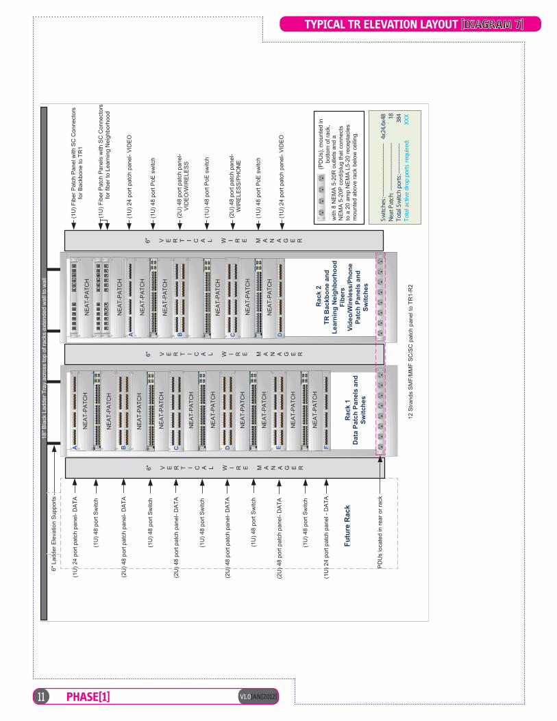
12S
trand
sS
MF/
MM
FS
C/S
Cpa
tch
pane
lto
TR1-
R2
Typi
calT
REl
evat
ion
Layo
ut
Switc
hes:
------
------
------
------
------
4x
24,6
x48
Neat
Pat
ch: -
------
------
------
------
--
18To
tal S
witc
h po
rts:--
------
------
---
3
84To
tal a
ctiv
e dr
op p
orts
requ
ired:
X
XX
(2U
)48
port
patc
hpa
nel-
DA
TA
(2U
)48
port
patc
hpa
nel-
DA
TA
(PD
Us)
,mou
nted
inbo
ttom
ofra
ck,
with
8N
EM
A5-
20R
outle
tsan
da
NE
MA
5-20
Pco
rd/p
lug
that
conn
ects
toa
20am
pN
EM
AL5
-20
rece
ptac
les
mou
nted
abov
era
ckbe
low
ceili
ng.
MODE
STACK
SPEE
DDUPL
XSTAT
MASTR
RPS
SYST
Cat
alys
t 375
0S
ER
IES
12
34
56
78
910
1X 2X
15X
16X
1112
1314
1516
1718
1920
2122
2324
2526
17X
18X
31X
32X
2728
2930
3132
3334
3536
3738
3940
4142
33X
34X
47X
48X
4344
4546
4748
24
13
NE
AT-
PA
TCH
NE
AT-
PA
TCH
NE
AT-
PA
TCH
NE
AT-
PA
TCH
NE
AT-
PA
TCH
MODE
STACK
SPEE
DDUPL
XSTAT
MASTR
RPS
SYST
Cat
alys
t 375
0S
ER
IES
12
34
56
78
910
1X 2X
15X
16X
1112
1314
1516
1718
1920
2122
2324
2526
17X
18X
31X
32X
2728
2930
3132
3334
3536
3738
3940
4142
33X
34X
47X
48X
4344
4546
4748
24
13
NE
AT-
PA
TCH
NE
AT-
PA
TCH
MODE
STACK
SPEE
DDUPL
XSTAT
MASTR
RPS
SYST
Cat
alys
t 375
0S
ER
IES
12
34
56
78
910
1X 2X
15X
16X
1112
1314
1516
1718
1920
2122
2324
2526
17X
18X
31X
32X
2728
2930
3132
3334
3536
3738
3940
4142
33X
34X
47X
48X
4344
4546
4748
24
13
A B C D EMODE
STACK
SPEE
DDUPL
XSTAT
MASTR
RPS
SYST
Cat
alys
t 375
0S
ER
IES
12
34
56
78
910
1X 2X
15X
16X
1112
1314
1516
1718
1920
2122
2324
2526
17X
18X
31X
32X
2728
2930
3132
3334
3536
3738
3940
4142
33X
34X
47X
48X
4344
4546
4748
24
13
NE
AT-
PA
TCH
NE
AT-
PA
TCH
E
NE
AT-
PA
TCH
6" V E R T I C A L W I R E M A N A G E R
6" V E R T I C A L W I R E M A N A G E R
6" V E R T I C A L W I R E M A N A G E RMODE
STACK
SPEE
DDUPL
XSTAT
MASTR
RPS
SYST
Cat
alys
t 375
0S
ER
IES
12
34
56
78
910
1X 2X
15X
16X
1112
1314
1516
1718
1920
2122
2324
2526
17X
18X
31X
32X
2728
2930
3132
3334
3536
3738
3940
4142
33X
34X
47X
48X
4344
4546
4748
24
13
F
Rac
k1
Dat
aPa
tch
Pane
lsan
dSw
itche
s
Rac
k2
TR B
ackb
one
and
Lear
ning
Nei
ghbo
rhoo
dFi
bers
Vide
o/W
irele
ss/P
hone
Patc
h Pa
nels
and
Switc
hes
NE
AT-
PA
TCH
MODE
STACK
SPEE
DDUPL
XSTAT
MASTR
RPS
SYST
Cat
alys
t 375
0S
ER
IES
12
34
56
78
910
1X 2X
15X
16X
1112
1314
1516
1718
1920
2122
2324
2526
17X
18X
31X
32X
2728
2930
3132
3334
3536
3738
3940
4142
33X
34X
47X
48X
4344
4546
4748
24
13
NE
AT-
PA
TCH
NE
AT-
PA
TCH
MODE
STACK
SPEE
DDUPL
XSTAT
MASTR
RPS
SYST
Cat
alys
t 375
0S
ER
IES
12
34
56
78
910
1X 2X
15X
16X
1112
1314
1516
1718
1920
2122
2324
2526
17X
18X
31X
32X
2728
2930
3132
3334
3536
3738
3940
4142
33X
34X
47X
48X
4344
4546
4748
24
13
NE
AT-
PA
TCH
MODE
STACK
SPEE
DDUPL
XSTAT
MASTR
RPS
SYST
Cat
alys
t 375
0S
ER
IES
12
34
56
78
910
1X 2X
15X
16X
1112
1314
1516
1718
1920
2122
2324
2526
17X
18X
31X
32X
2728
2930
3132
3334
3536
3738
3940
4142
33X
34X
47X
48X
4344
4546
4748
24
13
NE
AT-
PA
TCH
NE
AT-
PA
TCH
A B C
NE
AT-
PA
TCH
D
NE
AT-
PA
TCH
(1U
)48
port
PoE
switc
h
(1U
)Fib
er P
atch
Pan
el w
ith S
C C
onne
ctor
s
for B
ackb
one
to T
R1
(1U
)Fib
er P
atch
Pan
els
with
SC
Con
nect
ors
fo
r fib
er to
Lea
rnin
g N
eigh
borh
ood
(1U
)24
port
patc
hpa
nel-
VID
EO
(2U
)48
port
patc
hpa
nel-
VID
EO
/WIR
ELE
SS
(1U
)48
port
PoE
switc
h
(2U
)48
port
patc
hpa
nel-
WIR
ELE
SS
/PH
ON
E
(1U
)48
port
PoE
switc
h
(1U
)24
port
patc
hpa
nel-
VID
EO
(1U
)24
port
patc
hpa
nel-
DA
TA
(2U
)48
port
patc
hpa
nel-
DA
TA
(2U
)48
port
patc
hpa
nel-
DA
TA
(1U
)48
port
Sw
itch
(1U
)48
port
Sw
itch
(1U
)48
port
Sw
itch
(1U
)48
port
Sw
itch
(1U
)48
port
Sw
itch
18"B
lack
Ladd
erTr
ayac
ross
top
ofra
cks
exte
nded
wal
lto
wal
l
6"La
dder
Ele
vatio
nS
uppo
rts
(1U
) 24
port
patc
h pa
nel -
DA
TA
PD
Us
loca
ted
in re
ar o
r rac
k
Futu
re R
ack
11 V1.0JAN[2012]PHASE[1]
TYPICAL TR ELEVATION LAYOUT [DIAGRAM 7]
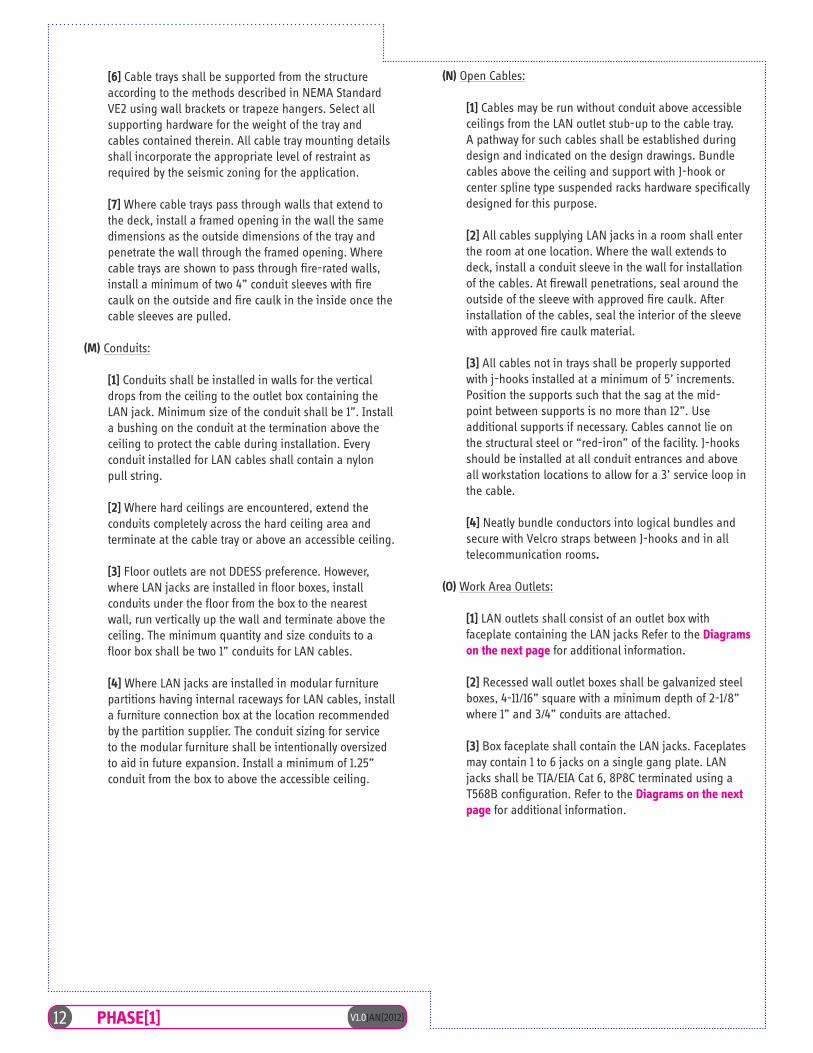
V1.0JAN[2012]12 PHASE[1]
[6] Cable trays shall be supported from the structure according to the methods described in NEMA Standard VE2 using wall brackets or trapeze hangers. Select all supporting hardware for the weight of the tray and cables contained therein. All cable tray mounting details shall incorporate the appropriate level of restraint as required by the seismic zoning for the application.
[7] Where cable trays pass through walls that extend to the deck, install a framed opening in the wall the same dimensions as the outside dimensions of the tray and penetrate the wall through the framed opening. Where cable trays are shown to pass through fire-rated walls, install a minimum of two 4” conduit sleeves with fire caulk on the outside and fire caulk in the inside once the cable sleeves are pulled.
(M) Conduits:
[1] Conduits shall be installed in walls for the vertical drops from the ceiling to the outlet box containing the LAN jack. Minimum size of the conduit shall be 1”. Install a bushing on the conduit at the termination above the ceiling to protect the cable during installation. Every conduit installed for LAN cables shall contain a nylon pull string.
[2] Where hard ceilings are encountered, extend the conduits completely across the hard ceiling area and terminate at the cable tray or above an accessible ceiling.
[3] Floor outlets are not DDESS preference. However, where LAN jacks are installed in floor boxes, install conduits under the floor from the box to the nearest wall, run vertically up the wall and terminate above the ceiling. The minimum quantity and size conduits to a floor box shall be two 1” conduits for LAN cables.
[4] Where LAN jacks are installed in modular furniture partitions having internal raceways for LAN cables, install a furniture connection box at the location recommended by the partition supplier. The conduit sizing for service to the modular furniture shall be intentionally oversized to aid in future expansion. Install a minimum of 1.25” conduit from the box to above the accessible ceiling.
(N) Open Cables:
[1] Cables may be run without conduit above accessible ceilings from the LAN outlet stub-up to the cable tray. A pathway for such cables shall be established during design and indicated on the design drawings. Bundle cables above the ceiling and support with J-hook or center spline type suspended racks hardware specifically designed for this purpose.
[2] All cables supplying LAN jacks in a room shall enter the room at one location. Where the wall extends to deck, install a conduit sleeve in the wall for installation of the cables. At firewall penetrations, seal around the outside of the sleeve with approved fire caulk. After installation of the cables, seal the interior of the sleeve with approved fire caulk material.
[3] All cables not in trays shall be properly supported with j-hooks installed at a minimum of 5’ increments. Position the supports such that the sag at the mid-point between supports is no more than 12”. Use additional supports if necessary. Cables cannot lie on the structural steel or “red-iron” of the facility. J-hooks should be installed at all conduit entrances and above all workstation locations to allow for a 3’ service loop in the cable.
[4] Neatly bundle conductors into logical bundles and secure with Velcro straps between J-hooks and in all telecommunication rooms.
(O) Work Area Outlets:
[1] LAN outlets shall consist of an outlet box with faceplate containing the LAN jacks Refer to the Diagrams on the next page for additional information.
[2] Recessed wall outlet boxes shall be galvanized steel boxes, 4-11/16” square with a minimum depth of 2-1/8” where 1” and 3/4” conduits are attached.
[3] Box faceplate shall contain the LAN jacks. Faceplates may contain 1 to 6 jacks on a single gang plate. LAN jacks shall be TIA/EIA Cat 6, 8P8C terminated using a T568B configuration. Refer to the Diagrams on the next page for additional information.
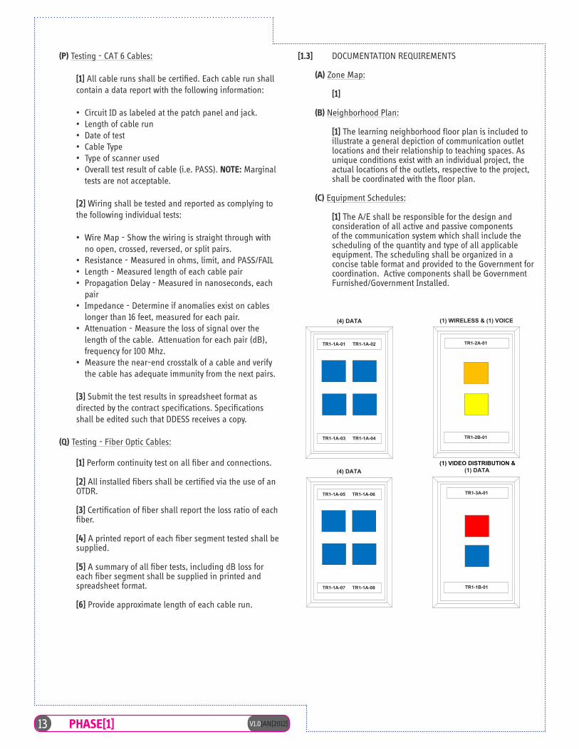
13 V1.0JAN[2012]PHASE[1]
(4) DATA (1) DATA
DoDEA/DDESS- WORKSTATION WALLPLATE CONFIGURATIONS:Typical Classroom
(1) WIRELESS & (1) VOICE(4) DATA
NOTES: Jacks to be placed in below order on any given faceplate so it matches the panels on the racks (left to right/top to bottom): DATA/BLUE- VIDEO/RED- WIRELESS/ORANGE- VOICE/YELLOW
TERMINATION CONFIGURATION: T568B N S Y NC S E R V IC E S , INC .C R AF T S MANS HIP B Y :
2004 N. HWY 360G R AND P R AIR IE , T X 75050www.nsyncservices .com1-866-706-7962
F ILE NAME :
UP DAT E D B Y :
DE S IG NE D B Y :
R E V IE WE D B Y :
OF
B UILDING NUMB E R :
DAT E D:
08/15/2011S HE E T NO.
R R S
DDE S S T Y P IC AL C LAS S R OOMWOR K S T AT ION F AC E P LAT E
C ONF IG UR AT ION
R R S
LD
DDE S S - T Y P IC AL C R F AC E P LAT E
T E LE C OMM R OOM/ZONE :
R andell S tewart, R C DDR C DD:
1 1ALL
DOMESTIC DEPENDENT ELEMENTARY AND SECONDARY SCHOOLS
U.S DEPARTMENT OF DEFENSE EDUCATION ACTIVITY
ALL
(1) VIDEO DISTRIBUTION &
TR1-1A-01 TR1-1A-02
TR1-1A-03 TR1-1A-04
TR1-1A-05 TR1-1A-06
TR1-1A-07 TR1-1A-08
TR1-2A-01
TR1-2B-01
TR1-3A-01
TR1-1B-01
(P) Testing - CAT 6 Cables:
[1] All cable runs shall be certified. Each cable run shall contain a data report with the following information:
• Circuit ID as labeled at the patch panel and jack.• Length of cable run• Date of test• Cable Type• Type of scanner used• Overall test result of cable (i.e. PASS). NOTE: Marginal
tests are not acceptable.
[2] Wiring shall be tested and reported as complying to the following individual tests:
• Wire Map - Show the wiring is straight through with no open, crossed, reversed, or split pairs.
• Resistance - Measured in ohms, limit, and PASS/FAIL• Length - Measured length of each cable pair• Propagation Delay - Measured in nanoseconds, each
pair• Impedance - Determine if anomalies exist on cables
longer than 16 feet, measured for each pair.• Attenuation - Measure the loss of signal over the
length of the cable. Attenuation for each pair (dB), frequency for 100 Mhz.
• Measure the near-end crosstalk of a cable and verify the cable has adequate immunity from the next pairs.
[3] Submit the test results in spreadsheet format as directed by the contract specifications. Specifications shall be edited such that DDESS receives a copy.
(Q) Testing - Fiber Optic Cables:
[1] Perform continuity test on all fiber and connections.
[2] All installed fibers shall be certified via the use of an OTDR.
[3] Certification of fiber shall report the loss ratio of each fiber.
[4] A printed report of each fiber segment tested shall be supplied.
[5] A summary of all fiber tests, including dB loss for each fiber segment shall be supplied in printed and spreadsheet format.
[6] Provide approximate length of each cable run.
[1.3] DOCUMENTATION REQUIREMENTS
(A) Zone Map:
[1]
(B) Neighborhood Plan:
[1] The learning neighborhood floor plan is included to illustrate a general depiction of communication outlet locations and their relationship to teaching spaces. As unique conditions exist with an individual project, the actual locations of the outlets, respective to the project, shall be coordinated with the floor plan.
(C) Equipment Schedules:
[1] The A/E shall be responsible for the design and consideration of all active and passive components of the communication system which shall include the scheduling of the quantity and type of all applicable equipment. The scheduling shall be organized in a concise table format and provided to the Government for coordination. Active components shall be Government Furnished/Government Installed.
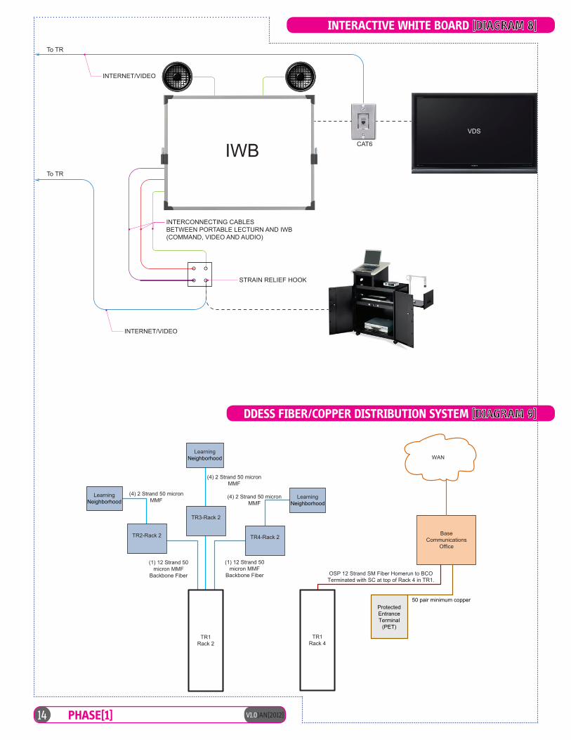
CAT6
VDS
IWBTo TR
To TR
INTERNET/VIDEO
STRAIN RELIEF HOOK
INTERCONNECTING CABLESBETWEEN PORTABLE LECTURN AND IWB(COMMAND, VIDEO AND AUDIO)
INTERNET/VIDEO
TR1Rack 4
DDESSFiber/Copper Distribution System
TR2-Rack 2
TR3-Rack 2
TR4-Rack 2
OSP 12 Strand SM Fiber Homerun to BCOTerminated with SC at top of Rack 4 in TR1.
BaseCommunications
Office
WAN
(1) 12 Strand 50micron MMF
Backbone Fiber
Learning (4) 2 Strand 50 micronMMF
Learning
(4) 2 Strand 50 micronMMF
Learning(4) 2 Strand 50 micronMMF
TR1Rack 2
(1) 12 Strand 50micron MMF
Backbone Fiber
Neighborhood
Neighborhood
50 pair minimum copper
Neighborhood
ProtectedEntranceTerminal
(PET)
V1.0JAN[2012]14 PHASE[1]
INTERACTIVE WHITE BOARD [DIAGRAM 8]
DDESS FIBER/COPPER DISTRIBUTION SYSTEM [DIAGRAM 9]

15 V1.0JAN[2012]PHASE[1]
CABLE PULL SCHEDULETelecom
RoomRack
DesignationPatch Panel
Port Number
Room Application Type
Cable ColorCable
Length POE (<250 Ft)
TR1 1 A 1 CR 101 Data BlueTR1 1 A 2 CR101 Data BlueTR1 1 A 3 CR101 Data BlueTR1 1 A 4 CR 102 Data BlueTR1 1 A 5 CR 102 Data BlueTR1 1 A 6 CR102 Data BlueTR1 1 A 7 CR 103 Data BlueTR1 1 A 8 CR 103 Data BlueTR1 1 A 9 CR 103 Data BlueTR1 1 A 10 Offices 104 Data BlueTR1 1 A 11 Offices 104 Data BlueTR1 1 A 12 Offices 104 Data BlueTR1 1 A 13 Offices 104 Data BlueTR1 1 A 14 Offices 104 Data BlueTR1 1 A 15 Offices 104 Data BlueTR1 1 A 16 Workrm 105 Data BlueTR1 1 A 17 CR 106 Data BlueTR1 1 A 18 CR 106 Data BlueTR1 1 A 19 CR 106 Data BlueTR1 1 A 20 CR 107 Data BlueTR1 1 A 21 CR 107 Data BlueTR1 1 A 22 CR 107 Data BlueTR1 1 A 23 Commons 108 Data BlueTR1 1 A 24 Commons 108 Data Blue
TR1 1 B 1 Commons 108 Data BlueTR1 1 B 2 Breakout 109 Data BlueTR1 1 B 3 CR 110 Data BlueTR1 1 B 4 CR 110 Data BlueTR1 1 B 5 CR 110 Data Blue
TR1 2 A 1 CR 101 Video RedTR1 2 A 2 CR 102 Video RedTR1 2 A 3 CR 103 Video RedTR1 2 A 4 CR106 Video RedTR1 2 A 5 CR 107 Video RedTR1 2 A 6 Commons 108 Video RedTR1 2 A 7 Commons 108 Video RedTR1 2 A 8 CR 110 Video Red
TR1 2 B 1 CR 101 Phone YellowTR1 2 B 2 CR 102 Phone YellowTR1 2 B 3 CR 103 Phone YellowTR1 2 B 4 Offices 104 Phone YellowTR1 2 B 5 Offices 104 Phone YellowTR1 2 B 6 Offices 104 Phone YellowTR1 2 B 7 Offices 104 Phone YellowTR1 2 B 8 Offices 104 Phone YellowTR1 2 B 9 Offices 104 Phone YellowTR1 2 B 10 Workrm 105 Phone YellowTR1 2 B 11 CR 106 Phone YellowTR1 2 B 12 CR 107 Phone YellowTR1 2 B 13 Commons 108 Phone YellowTR1 2 B 14 CR 110 Phone Yellow
TR1 2 C 1 CR 101 Wireless OrangeTR1 2 C 2 CR 102 Wireless OrangeTR1 2 C 3 CR 103 Wireless OrangeTR1 2 C 4 Offices 104 Wireless OrangeTR1 2 C 5 CR 106 Wireless OrangeTR1 2 C 6 CR 107 Wireless OrangeTR1 2 C 7 Commons 108 Wireless OrangeTR1 2 C 8 CR 110 Wireless Orange
Remarks
White Board
White Board
White Board
White BoardWhite Board
White Board
White Board
White BoardWhite BoardWhite BoardWhite BoardWhite BoardWhite BoardWhite BoardWall mounted flat screen
CABLE PULL SCHEDULE [DIAGRAM 10]
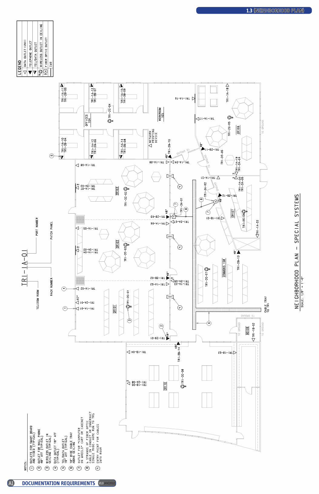
V1.0JAN[2012]A1 DOCUMENTATION REQUIREMENTS
1.3 (NEIGHBORHOOD PLAN)1
23
45
D C B A
80”
OUTLET FOR “COMPUTER
ON WHEELS” CART OR CABINET
6 STRANDS OF FIBER OPTIC
CABLE IN CONDUIT OR INNERDUCT
SINGLE MODE. HOME RUN TO TR1
ENTRY POINT FOR CABLES
INTO ROOM
9
99
9
IWB
(UNO)
NETWORK
PRINTING
DEVICE
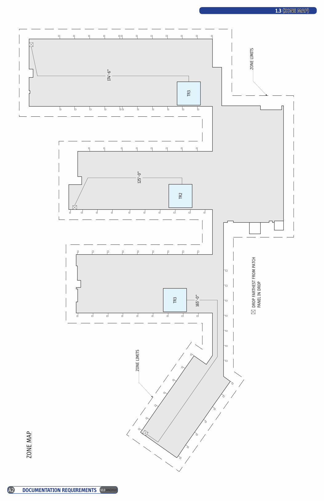
ZON
E M
AP
ZON
E LI
MIT
S
DRO
P FA
RTH
EST
FRO
M P
ATC
HPA
NEL
IN D
ROP
ZON
E LI
MIT
S
165’
-0”
TR3
TR2
TR3
125’
-0”
174’
-6”
V1.0JAN[2012]A2 DOCUMENTATION REQUIREMENTS
1.3 (ZONE MAP)
Education Facilities Specification Change Approval
Attached are the original Change Request and subsequent revision to the Educational Facilities
Specification for your approval.
Summary of any unforeseen issues in making this change:
Other Area Concurrence:
DDESS:
DoDDS-Europe:
DoDDS-Pacific:
HQ DoDEA Routing
DoDEA Facilities Chief:
DoDEA Logistics Division:
DoDEA Education Chief:
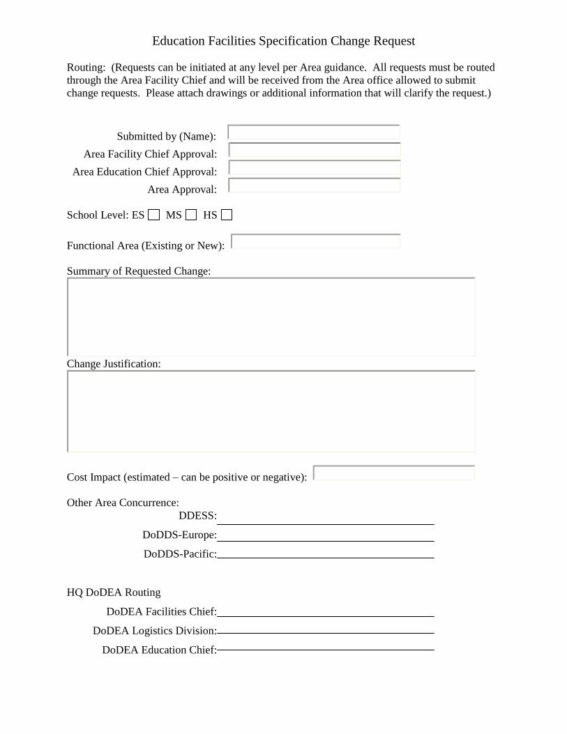
Education Facilities Specification Change Request
Routing: (Requests can be initiated at any level per Area guidance. All requests must be routed
through the Area Facility Chief and will be received from the Area office allowed to submit
change requests. Please attach drawings or additional information that will clarify the request.)
Submitted by (Name):
Area Facility Chief Approval:
Area Education Chief Approval:
Area Approval:
School Level: ES MS HS
Functional Area (Existing or New):
Summary of Requested Change:
Change Justification:
Cost Impact (estimated – can be positive or negative):
Other Area Concurrence:
DDESS:
DoDDS-Europe:
DoDDS-Pacific:
HQ DoDEA Routing
DoDEA Facilities Chief:
DoDEA Logistics Division:
DoDEA Education Chief: