Embed Size (px)
Citation preview

AMSC N/A AREA PACK
INCH-POUND MIL-STD-648D10 April 2008 SUPERSEDING MIL-STD-648C11 FEBRUARY 1999
DEPARTMENT OF DEFENSE DESIGN CRITERIA STANDARD
SPECIALIZED SHIPPING CONTAINERS

MIL-STD-648D
ii
FOREWORD
1. This design criteria standard is approved for use by all Departments and Agencies of the Department of Defense.
2. This standard establishes the general design criteria and associated tests for specialized shipping containers used by the Department of Defense. The initial step in the creation of a specialized shipping container is to distill the general design criteria within this document into specific design criteria. By filling out a container requirements checklist (see Appendix A) prior to initiating the design, a focused list of unique needs can be identified to ensure that the container’s contents are properly protected throughout its planned distribution and stowage logistics.
3. A specialized container is uniquely configured to support and protect its prescribed contents while being handled, stored, shipped to, and unpacked by the user; or to protect personnel and equipment from hazardous contents. Containers of this type frequently incorporate energy absorbing systems, temperature control systems, or special features to make handling or shipment possible, easier, or safer. Engineering drawings, or equivalent, are used to define form, fit, function, materials, tolerances, and manufacturing techniques.
4. A specialized shipping container is designed for use with a specific item when general container specifications are not sufficiently detailed to assure required protection, safety, reliability, maintainability, or configuration control. The need for a specialized container may arise with any deliverable item and invariably does so with nuclear and conventional ammunition and explosives. The container may be the result of a completely original design effort or of the modification of existing or standard container designs.
5. Copies of this standard are available online at http://assist.daps.dla.mil/quicksearch/ or from the Standardization Document Order Desk, 700 Robbins Avenue, Building 4D, Philadelphia, PA 19111-5094.
6. Comments, suggestions, or questions on this document should be addressed to Commander, Indian Head Division, Naval Surface Warfare Center, Code E11G3, 4072 N. Jackson Rd, Suite 106, Indian Head, MD 20640-5114 or emailed to [email protected]. Since contact information can change, you may want to verify the currency of this address information using the ASSIST Online database at http://assist.daps.dla.mil.

MIL-STD-648D
iii
CONTENTS
PARAGRAPH PAGE
1. SCOPE......................................................................................................................................................................1 1.1 Scope.................................................................................................................................................................1
2. APPLICABLE DOCUMENTS ................................................................................................................................1 2.1 General..............................................................................................................................................................1 2.2 Government documents ....................................................................................................................................1
2.2.1 Specifications, standards, and handbooks ................................................................................................1 2.2.2 Other Government documents, drawings, and publications.....................................................................2
2.3 Non-Government publications..........................................................................................................................5 2.4 Order of precedence..........................................................................................................................................7
3. DEFINITIONS .........................................................................................................................................................8 3.1 General..............................................................................................................................................................8
3.1.1 Ambient (temperature) .............................................................................................................................8 3.1.2 Anthropometry .........................................................................................................................................8 3.1.3 Clinch .......................................................................................................................................................8 3.1.4 Commercial-off-the-shelf (COTS) ...........................................................................................................8 3.1.5 Competent authority.................................................................................................................................8 3.1.6 Connected replenishment-at-sea (CONREP) ...........................................................................................8 3.1.7 Cracking pressure (relief valve) ...............................................................................................................8 3.1.8 Cushion (compressive) creep ...................................................................................................................8 3.1.9 Distributed isolation material (DIM)........................................................................................................8 3.1.10 Elastomer................................................................................................................................................8 3.1.11 Energy absorbing devices.......................................................................................................................8 3.1.12 Explosive limit .......................................................................................................................................8 3.1.13 Faying surfaces.......................................................................................................................................8 3.1.14 Fire-retardant materials ..........................................................................................................................8 3.1.15 Flexible barriers .....................................................................................................................................8 3.1.16 Fragility levels........................................................................................................................................9 3.1.17 Galling....................................................................................................................................................9 3.1.18 Human systems integration (HSI) ..........................................................................................................9 3.1.19 Hydrogen embrittlement ........................................................................................................................9 3.1.20 Hygroscopic ...........................................................................................................................................9 3.1.21 Intermediate bulk container (IBC)..........................................................................................................9 3.1.22 Level A...................................................................................................................................................9 3.1.23 Level B...................................................................................................................................................9 3.1.24 Life cycle environmental profile (LCEP).............................................................................................10 3.1.25 Minimum flow rate (relief valve) .........................................................................................................10 3.1.26 Nematode .............................................................................................................................................10 3.1.27 Non-combustible materials...................................................................................................................10 3.1.28 Non-person portable container .............................................................................................................10 3.1.29 Passivation............................................................................................................................................10 3.1.30 Reseal pressure (relief valve) ...............................................................................................................10 3.1.31 Shock response spectrum (SRS)...........................................................................................................10 3.1.32 Specialized shipping container.............................................................................................................10 3.1.33 Springwood ..........................................................................................................................................10 3.1.34 Standard parts and materials.................................................................................................................10

MIL-STD-648D
iv
PARAGRAPH PAGE
3.1.35 STREAM..............................................................................................................................................10 3.1.36 Summerwood .......................................................................................................................................10 3.1.37 Sympathetic detonation ........................................................................................................................10 3.1.38 Transmissibility....................................................................................................................................11 3.1.39 Underway replenishment at sea (UNREP) ...........................................................................................11 3.1.40 Unit load...............................................................................................................................................11 3.1.41 Vertical replenishment at sea (VERTREP) ..........................................................................................11
4. GENERAL REQUIREMENTS..............................................................................................................................11 4.1 General............................................................................................................................................................11
4.1.1 Hazardous materials and devices ...........................................................................................................11 4.2 Interfaces.........................................................................................................................................................11
4.2.1 Contents .................................................................................................................................................11 4.2.2 Handling equipment ...............................................................................................................................11 4.2.3 Distribution network ..............................................................................................................................12 4.2.4 Unit load compatibility...........................................................................................................................12
4.3 Configuration ..................................................................................................................................................12 4.4 Transportability requirements .........................................................................................................................12
4.4.1 Sensitive materials (transportation security) ..........................................................................................12 4.4.2 Transfer-at-sea (UNREP).......................................................................................................................12
4.5 Cube and weight .............................................................................................................................................12 4.5.1 Naval aircraft carrier container size limits .............................................................................................13
4.6 Materials and manufacturing methods ............................................................................................................13 4.6.1 Cadmium-plated hardware .....................................................................................................................13
4.6.1.1 Plating............................................................................................................................................13 4.6.2 Dissimilar metals....................................................................................................................................14
4.6.2.1 Acceptance criteria ........................................................................................................................14 4.6.3 Screw threads .........................................................................................................................................14 4.6.4 Elastomeric parts ....................................................................................................................................14 4.6.5 Standard parts and materials...................................................................................................................14 4.6.6 Material stability ....................................................................................................................................15 4.6.7 Internal packaging materials ..................................................................................................................15
4.6.7.1 Materials compatibility..................................................................................................................15 4.6.7.2 Blocking and bracing materials .....................................................................................................16 4.6.7.3 Cushioning materials .....................................................................................................................19 4.6.7.4 Resilient mounts ............................................................................................................................20 4.6.7.5 Dynamic characteristics.................................................................................................................20
4.6.8 Interchangeability...................................................................................................................................21 4.6.9 Support fasteners and closure devices....................................................................................................20 4.6.10 Wood treatment and preservation.........................................................................................................20
4.6.10.1 Nematodes ...................................................................................................................................21 4.6.11 Nonmetallic materials ..........................................................................................................................21 4.6.12 Corrosion..............................................................................................................................................21 4.6.13 Stainless steel .......................................................................................................................................21
4.7 Fire performance.............................................................................................................................................21 4.8 Drainage..........................................................................................................................................................21 4.9 Records receptacle ..........................................................................................................................................21

MIL-STD-648D
v
PARAGRAPH PAGE
4.10 Closure devices .............................................................................................................................................22 4.11 Static electricity ............................................................................................................................................22 4.12 Preservation ..................................................................................................................................................22 4.13 Clean-room operations..................................................................................................................................22 4.14 Security seal ..................................................................................................................................................22 4.15 Protection of contents against corrosion and water damage .........................................................................23
4.15.1 General .................................................................................................................................................23 4.15.2 Closed containers without auxiliary barriers ........................................................................................23
4.15.2.1 Ventilation ...................................................................................................................................23 4.15.2.2 Drainage ......................................................................................................................................23
4.15.3 Closed containers with auxiliary barriers .............................................................................................23 4.15.4 Integral-barrier containers ....................................................................................................................23
4.15.4.1 Structural .....................................................................................................................................23 4.15.4.2 Leakage .......................................................................................................................................23 4.15.4.3 Closures (except removable head drums)....................................................................................24 4.15.4.4 Desiccant storage.........................................................................................................................24 4.15.4.5 Humidity indicator.......................................................................................................................24 4.15.4.6 Pressurizing fitting.......................................................................................................................24 4.15.4.7 Leakage indicator ........................................................................................................................25 4.15.4.8 Container accessories ..................................................................................................................25 4.15.4.9 Transparent window in auxiliary barrier .....................................................................................25 4.15.4.10 Special requirements for non-breathing integral-barrier containers ..........................................25 4.15.4.11 Special requirements for controlled-breathing integral-barrier containers ................................25 4.15.4.12 Special requirements for free-breathing containers ...................................................................25 4.15.4.13 Observation window..................................................................................................................25
4.15.4.13.1 Alternate observation window location ............................................................................26 4.16 Stacking and stowing ....................................................................................................................................26
4.16.1 General .................................................................................................................................................26 4.16.2 Stacking stability ..................................................................................................................................26 4.16.3 Stackability...........................................................................................................................................26 4.16.4 Distributed load....................................................................................................................................26 4.16.5 Stacking strength ..................................................................................................................................26
4.17 Handling........................................................................................................................................................26 4.17.1 General .................................................................................................................................................26 4.17.2 Manual lifting/carrying ........................................................................................................................27
4.17.2.1 Handle characteristics..................................................................................................................27 4.17.2.2 Handhold characteristics..............................................................................................................27
4.17.3 Hoisting................................................................................................................................................28 4.17.3.1 Hoisting provisions......................................................................................................................28
4.17.4 Tiedown................................................................................................................................................29 4.17.5 Skids.....................................................................................................................................................29 4.17.6 Forklift truck compatibility ..................................................................................................................29
4.17.6.1 Containers having a length greater than 88 inches ......................................................................29 4.17.6.2 Containers ranging in length from 50 to 88 inches......................................................................30 4.17.6.3 Pallet size containers (52 by 44 inches or smaller)......................................................................30 4.17.6.4 Direct interface with military aircraft loading operations............................................................31

MIL-STD-648D
vi
PARAGRAPH PAGE
4.17.6.5 Secondary uses for fork pockets ..................................................................................................31 4.17.7 Shipboard handling ..............................................................................................................................31 4.17.8 Handling provision maintainability......................................................................................................31
4.18 Special protection devices.............................................................................................................................32 4.18.1 Temperature control .............................................................................................................................32 4.18.2 Field-force protection...........................................................................................................................32 4.18.3 Magnetic shielding ...............................................................................................................................32
4.19 Protecting and identifying the container .......................................................................................................32 4.19.1 Painting requirements...........................................................................................................................32 4.19.2 Identification and instructional markings.............................................................................................32
4.19.2.1 Identification marking .................................................................................................................32 4.19.2.2 Basic instructional markings........................................................................................................32 4.19.2.3 Color coding ................................................................................................................................33
4.19.3 Container markings ..............................................................................................................................33 4.20 Nuclear, biological, chemical (NBC) survivability.......................................................................................33 4.21 Human systems integration (HSI).................................................................................................................33 4.22 Pallet jack compatibility................................................................................................................................34
5. DETAILED REQUIREMENTS.............................................................................................................................34 5.1 Fit and compatibility .......................................................................................................................................34
5.1.1 General ...................................................................................................................................................34 5.1.2 Fit test.....................................................................................................................................................34
5.2 Mechanical shock............................................................................................................................................34 5.2.1 General ...................................................................................................................................................34
5.2.1.1 Acceptance criteria ........................................................................................................................34 5.2.1.2 Test loads.......................................................................................................................................35 5.2.1.3 Instrumentation..............................................................................................................................35 5.2.1.4 Temperature combined with shock................................................................................................36 5.2.1.5 Drop surface recommendation.......................................................................................................36
5.2.2 Repetitive shock test...............................................................................................................................36 5.2.2.1 Repetitive shock test (stacked) ......................................................................................................36
5.2.3 Drop test (free-fall).................................................................................................................................37 5.2.4 Cornerwise-drop (rotational) test ...........................................................................................................37 5.2.5 Edgewise-drop (rotational) test ..............................................................................................................37 5.2.6 Tipover test.............................................................................................................................................37 5.2.7 Impact test ..............................................................................................................................................37
5.2.7.1 Impact test (stacked)......................................................................................................................38 5.2.8 Transfer-at-sea shock test.......................................................................................................................39 5.2.9 Shipboard shock test...............................................................................................................................39
5.2.9.1 Grades of containers ......................................................................................................................39 5.2.9.2 Classes of containers .....................................................................................................................39 5.2.9.3 Pass-fail criteria .............................................................................................................................39 5.2.9.4 Class I containers (foam or rubberized fiber isolation systems) ....................................................40
5.2.9.4.1 Container testing ...................................................................................................................40 5.2.9.4.2 Weight limitations.................................................................................................................40 5.2.9.4.3 Size limitations .....................................................................................................................40 5.2.9.4.4 Testing orientations...............................................................................................................40

MIL-STD-648D
vii
PARAGRAPH PAGE
5.2.9.4.5 Method of securing the container to the MWSM..................................................................40 5.2.9.4.6 Design criteria.......................................................................................................................40 5.2.9.4.7 Floating shock platform (FSP testing) ..................................................................................40 5.2.9.4.8 Heavyweight shock test ........................................................................................................40 5.2.9.4.9 Deck-stowed containers ........................................................................................................40 5.2.9.4.10 Method of securing the container to the FSP ......................................................................40 5.2.9.4.11 Chain tiedown assembly .....................................................................................................40
5.2.9.5 Class II containers (resilient mount isolation systems)..................................................................40 5.2.9.5.1 Testing to hi-shock events ....................................................................................................41 5.2.9.5.2 Chain tiedown assembly .......................................................................................................41
5.2.9.6 Shipboard shock test (eligibility)...................................................................................................41 5.2.10 Safety drop test.....................................................................................................................................41 5.2.11 Railcar shock test for nuclear weapon containers ................................................................................41
5.3 Vibration .........................................................................................................................................................41 5.3.1 General ...................................................................................................................................................41 5.3.2 Random vibration...................................................................................................................................42
5.3.2.1 Truck transportation over U.S. highway........................................................................................43 5.3.2.2 Mission/field transportation...........................................................................................................43 5.3.2.3 Aircraft jet .....................................................................................................................................43 5.3.2.4 Aircraft propeller ...........................................................................................................................43 5.3.2.5 Ship-surface ship ...........................................................................................................................43
5.3.3 Sinusoidal testing ...................................................................................................................................43 5.3.3.1 Resonance survey and dwell test ...................................................................................................44
5.3.4 Sinusoidal cycling test............................................................................................................................44 5.4 Shock mount aging .........................................................................................................................................44
5.4.1 Salt fog test.............................................................................................................................................44 5.4.2 Ozone resistance test ..............................................................................................................................44 5.4.3 Air-heat aging test ..................................................................................................................................44
5.5 Structural integrity ..........................................................................................................................................44 5.5.1 General ...................................................................................................................................................44 5.5.2 Pressure test............................................................................................................................................44
5.5.2.1 Test pressures ................................................................................................................................45 5.6 Leakage integrity ............................................................................................................................................45
5.6.1 General ...................................................................................................................................................45 5.6.2 Leak test .................................................................................................................................................45
5.6.2.1 Test pressures ................................................................................................................................45 5.7 Superimposed load..........................................................................................................................................45
5.7.1 General ...................................................................................................................................................45 5.7.2 Load test (like containers) ......................................................................................................................45 5.7.3 Load test (unlike containers) ..................................................................................................................45
5.8 Hoisting fitting and tiedown attachment points ..............................................................................................45 5.8.1 General ...................................................................................................................................................46 5.8.2 Acceptance criteria.................................................................................................................................46 5.8.3 Hoisting fittings strength test .................................................................................................................46 5.8.4 Tiedown strength test .............................................................................................................................46 5.8.5 Single hoisting fitting strength test.........................................................................................................46

MIL-STD-648D
viii
PARAGRAPH PAGE
5.9 Forklift truck (fully captive fork tine enclosures) compatibility test ..............................................................47 5.9.1 Forklift truck (non-captive lift) compatibility test..................................................................................47
5.10 Handlift truck MK 45 compatibility .............................................................................................................47 5.10.1 General .................................................................................................................................................47 5.10.2 Static overload......................................................................................................................................47 5.10.3 Shock test .............................................................................................................................................47 5.10.4 Rolling test ...........................................................................................................................................47
5.11 Fire performance requirements .....................................................................................................................47 5.11.1 Flame spread index test ........................................................................................................................47 5.11.2 Smoke density test................................................................................................................................47 5.11.3 Stacked container fire test ....................................................................................................................48
5.12 Measurement of magnetic fields ...................................................................................................................49 5.13 Sympathetic detonation.................................................................................................................................49 5.14 Testing sequences .........................................................................................................................................49
5.14.1 Army containers ...................................................................................................................................49 5.14.2 Air Force containers .............................................................................................................................49 5.14.3 Navy containers....................................................................................................................................55
6. NOTES ...................................................................................................................................................................55 6.1 Intended use ....................................................................................................................................................55 6.2 Acquisition requirements ................................................................................................................................55 6.3 Subject term (key word) listing.......................................................................................................................55 6.4 International standardization agreement implementation ...............................................................................55 6.5 Changes from previous issue ..........................................................................................................................55

MIL-STD-648D
ix
FIGURE PAGE 1. Recommended average moisture content for use of wood products in various areas of the United States ............17 2. Standard fork tine spacings.....................................................................................................................................30 3. Pallet size container fork tine spacings...................................................................................................................30 4. Samples of symmetrical packaging ........................................................................................................................38 5 Front view of stacked container fire test setup ........................................................................................................48 6. Plan view of stacked container fire test setup.........................................................................................................49 7. Test sequence for containers under 150 pounds and issued to ground troops ........................................................50 8. Test sequence for containers 150 pounds or more and issued to ground troops .....................................................52 9. Air Force test sequence for containers under 150 pounds ......................................................................................53 10. Air Force test sequence for containers over 150 pounds ......................................................................................54 B-1. Records holder....................................................................................................................................................63 B-2. Center lift............................................................................................................................................................64 B-3. Sling, hoisting MK 105 MOD 0 .........................................................................................................................65 B-4. Sling leg 4,000 pound capacity...........................................................................................................................66 B-5. Holder, records ...................................................................................................................................................67 B-6. Plug humidity indicator ......................................................................................................................................68 B-7. Endlift-adapter ....................................................................................................................................................69 B-8. Sling, container lifting MK 109 MOD 1.............................................................................................................70 B-9. Fork pocket (DWG 5167633) .............................................................................................................................71 B-10. Fork pocket (DWG 5167693) ...........................................................................................................................72 B-11. Latch .................................................................................................................................................................73 B-12. Handle...............................................................................................................................................................74 B-13. Observation window.........................................................................................................................................75 B-14. Access port .......................................................................................................................................................76 B-15. Latch, wide handle............................................................................................................................................77 B-16. Shackle .............................................................................................................................................................78 B-17. Valve, breather..................................................................................................................................................79 B-18. Desiccator .........................................................................................................................................................80 B-19. Latch .................................................................................................................................................................81 B-20. Latch, CRES .....................................................................................................................................................82 B-21. Ring, container lift ............................................................................................................................................83 B-22. Container endlift interface (sheet 1 of 3 DWG 6214131).................................................................................84 B-23. Container endlift interface (sheet 2 of 3 DWG 6214131).................................................................................85 B-24. Container endlift interface (sheet 3 of 3 DWG 6214131).................................................................................86 C-1. Electrostatic test chamber ...................................................................................................................................89 C-2. Electrostatic test arrangement.............................................................................................................................90 C-3. Electrostatic test..................................................................................................................................................91 C-4. Electrostatic detector ..........................................................................................................................................92 C-5. Electrode.............................................................................................................................................................93 D-1. Top superimposed-load test................................................................................................................................96 E-1. Top superimposed-load test ................................................................................................................................99 G-1. Free-fall drop test .............................................................................................................................................107 H-1. Cornerwise drop (rotational) ............................................................................................................................111 I-1. Edgewise drop (rotational).................................................................................................................................115 L-1. Incline-impact test.............................................................................................................................................121

MIL-STD-648D
x
M-1. Pendulum-impact test ......................................................................................................................................124 N-1. Test envelope 2 to 500 cycles per second for vibration (sinusoidal motion) test .............................................128 P-1. Slings placed around specimen with load superimposed ..................................................................................138 P-2. Hoisting with sling attachment provisions ........................................................................................................139 P-3. Hoisting with grabs ...........................................................................................................................................140
TABLE PAGE I. Common standard parts for Navy containers ..........................................................................................................15 II. Recommended average moisture content in various areas1/ of the United States .................................................17 III. Lateral loading of nails .........................................................................................................................................18 IV. Expected temperature extremes............................................................................................................................36 V. Mechanical shock input locations to containers ....................................................................................................38 VI. Shock test for containers-at-sea............................................................................................................................39 G-I. Height of free-fall drops for containers of various sizes and weights ...............................................................106 H-I. Height of rotational drops for containers of various sizes and weights.............................................................110 I-I. Height of rotational drops for containers of various sizes and weights ..............................................................114
APPENDIX A .............................................................................................................................................................56 A.1 SCOPE.................................................................................................................................................................56
A.1.1 Scope...........................................................................................................................................................56
APPENDIX B..............................................................................................................................................................62 B.1 SCOPE.................................................................................................................................................................62
B.1.1 Scope...........................................................................................................................................................62
APPENDIX C..............................................................................................................................................................87 C.1 SCOPE.................................................................................................................................................................87
C.1.1 Scope...........................................................................................................................................................87 C.2 DEFINITION.......................................................................................................................................................87
C.2.1 Electrostatic properties ................................................................................................................................87 C.3 APPARATUS ......................................................................................................................................................87 C.4 SPECIMENS........................................................................................................................................................87 C.5 CONDITIONING ................................................................................................................................................87
C.5.1 Test environment.........................................................................................................................................87 C.6 PROCEDURE......................................................................................................................................................87 C.7 REPORT ..............................................................................................................................................................88 C.8 NOTES.................................................................................................................................................................88
APPENDIX D .............................................................................................................................................................94 D.1 SCOPE.................................................................................................................................................................94
D.1.1 Scope...........................................................................................................................................................94 D.2 DEFINITIONS ....................................................................................................................................................94
D.2.1 Packing........................................................................................................................................................94 D.2.1.1 Level A...............................................................................................................................................94 D.2.1.2 Level B ...............................................................................................................................................94
D.2.2 Top dunnage................................................................................................................................................94 D.3 APPARATUS......................................................................................................................................................94
D.3.1 Top superimposed-load test ........................................................................................................................94

MIL-STD-648D
xi
D.4 SPECIMEN .........................................................................................................................................................95 D.4.1 Contents of container ..................................................................................................................................95
D.5 CONDITIONING OF SPECIMEN .....................................................................................................................95 D.5.1 Test specimen..............................................................................................................................................95
D.6 PROCEDURE......................................................................................................................................................95 D.7 REPORT..............................................................................................................................................................95 D.8 NOTES ................................................................................................................................................................96
APPENDIX E..............................................................................................................................................................97 E.1 SCOPE .................................................................................................................................................................97
E.1.1 Scope ...........................................................................................................................................................97 E.2 DEFINITIONS.....................................................................................................................................................97
E.2.1 Packing ........................................................................................................................................................97 E.2.1.1 Level A ...............................................................................................................................................97 E.2.1.2 Level B................................................................................................................................................97
E.2.2 Top dunnage ................................................................................................................................................97 E.3 APPARATUS ......................................................................................................................................................97
E.3.1 Top superimposed-load test.........................................................................................................................97 E.4 SPECIMEN..........................................................................................................................................................97
E.4.1 Contents of container...................................................................................................................................97 E.5 CONDITIONING OF SPECIMEN......................................................................................................................97
E.5.1 Test specimen ..............................................................................................................................................97 E.6 PROCEDURE......................................................................................................................................................97 E.7 REPORT ..............................................................................................................................................................98 E.8 NOTES.................................................................................................................................................................98
APPENDIX F ............................................................................................................................................................100 F.1 SCOPE ...............................................................................................................................................................100
F.1.1 Scope .........................................................................................................................................................100 F.2 DEFINITIONS ...................................................................................................................................................100
F.2.1 Shock .........................................................................................................................................................100 F.2.2 Vibration....................................................................................................................................................100
F.3 APPARATUS.....................................................................................................................................................100 F.3.1 Platform .....................................................................................................................................................100 F.3.2 Restraining devices....................................................................................................................................100
F.4 SPECIMENS......................................................................................................................................................100 F.4.1 Contents of container .................................................................................................................................100
F.5 CONDITIONING...............................................................................................................................................100 F.5.1 Test specimen ............................................................................................................................................100
F.6 PROCEDURE ....................................................................................................................................................101 F.7 REPORT.............................................................................................................................................................101 F.8 NOTES...............................................................................................................................................................102
APPENDIX G ...........................................................................................................................................................103 G.1 SCOPE...............................................................................................................................................................103
G.1.1 Scope.........................................................................................................................................................103 G.2 DEFINITIONS ..................................................................................................................................................103
G.2.1 Packing......................................................................................................................................................103

MIL-STD-648D
xii
G.2.1.1 Level A.............................................................................................................................................103 G.2.1.2 Level B .............................................................................................................................................103
G.3 APPARATUS....................................................................................................................................................103 G.4 SPECIMEN .......................................................................................................................................................104
G.4.1 Contents of container ................................................................................................................................104 G.5 CONDITIONING..............................................................................................................................................104
G.5.1 Test specimen............................................................................................................................................104 G.6 PROCEDURE....................................................................................................................................................104
G.6.1 Bags ..........................................................................................................................................................104 G.6.2 Cylindrical containers ...............................................................................................................................104 G.6.3 Rectangular containers ..............................................................................................................................104 G.6.4 Drop height ...............................................................................................................................................105
G.7 REPORT............................................................................................................................................................105 G.8 NOTES ..............................................................................................................................................................105
APPENDIX H ...........................................................................................................................................................108 H.1 SCOPE...............................................................................................................................................................108
H.1.1 Scope.........................................................................................................................................................108 H.2 DEFINITIONS ..................................................................................................................................................108
H.2.1 Large shipping containers .........................................................................................................................108 H.2.2 Packing......................................................................................................................................................108
H.2.2.1 Level A.............................................................................................................................................108 H.2.2.2 Level B .............................................................................................................................................108
H.3 APPARATUS....................................................................................................................................................108 H.3.1 Cornerwise-drop test .................................................................................................................................108
H.4 SPECIMEN .......................................................................................................................................................109 H.4.1 Contents of container ................................................................................................................................109
H.5 CONDITIONING OF SPECIMEN ...................................................................................................................109 H.5.1 Test specimen............................................................................................................................................109
H.6 PROCEDURE....................................................................................................................................................109 H.6.1 Number and height of drops......................................................................................................................109
H.7 REPORT............................................................................................................................................................109 H.8 NOTES ..............................................................................................................................................................110
APPENDIX I .............................................................................................................................................................112 I.1 SCOPE ................................................................................................................................................................112
I.1.1 Scope ..........................................................................................................................................................112 I.2 DEFINITIONS....................................................................................................................................................112
I.2.1 Large shipping containers...........................................................................................................................112 I.2.2 Packing .......................................................................................................................................................112
I.2.2.1 Level A ..............................................................................................................................................112 I.2.2.2 Level B...............................................................................................................................................112
I.3 APPARATUS......................................................................................................................................................112 I.3.1 Edgewise-drop test .....................................................................................................................................112
I.4 SPECIMEN .........................................................................................................................................................113 I.4.1 Contents of container..................................................................................................................................113
I.5 CONDITIONING OF SPECIMEN.....................................................................................................................113 I.5.1 Test specimen .............................................................................................................................................113

MIL-STD-648D
xiii
I.6 PROCEDURE .....................................................................................................................................................113 I.6.1 Number and height of drops .......................................................................................................................113
I.7 REPORT .............................................................................................................................................................113 I.8 NOTES................................................................................................................................................................114
APPENDIX J.............................................................................................................................................................116 J.1 SCOPE ................................................................................................................................................................116
J.1.1 Scope ..........................................................................................................................................................116 J.2 DEFINITION......................................................................................................................................................116
J.2.1 Large shipping containers...........................................................................................................................116 J.3 APPARATUS .....................................................................................................................................................116
J.3.1 Tipover test.................................................................................................................................................116 J.4 SPECIMEN.........................................................................................................................................................116
J.4.1 Contents of container..................................................................................................................................116 J.5 CONDITIONING OF SPECIMEN.....................................................................................................................116
J.5.1 Test specimen.............................................................................................................................................116 J.6 PROCEDURE.....................................................................................................................................................116
J.6.1 Number and direction of tipover ................................................................................................................116 J.7 REPORT .............................................................................................................................................................116 J.8 NOTES................................................................................................................................................................117
APPENDIX K ...........................................................................................................................................................118 K.1 SCOPE...............................................................................................................................................................118
K.1.1 Scope.........................................................................................................................................................118 K.2 DEFINITIONS ..................................................................................................................................................118 K.3 APPARATUS....................................................................................................................................................118 K.4 SPECIMEN .......................................................................................................................................................118
K.4.1 Contents of container ................................................................................................................................118 K.5 CONDITIONING..............................................................................................................................................116
K.5.1 Test specimen............................................................................................................................................118 K.6 PROCEDURE....................................................................................................................................................118 K.7 REPORT............................................................................................................................................................118 K.8 NOTES ..............................................................................................................................................................119
APPENDIX L............................................................................................................................................................120 L.1 SCOPE ...............................................................................................................................................................120
L.1.1 Scope .........................................................................................................................................................120 L.2 DEFINITION .....................................................................................................................................................120
L.2.1 Incline impact tester ..................................................................................................................................120 L.3 APPARATUS ....................................................................................................................................................120
L.3.1 Inclined track.............................................................................................................................................120 L.4 SPECIMEN........................................................................................................................................................120
L.4.1 Contents of container.................................................................................................................................120 L.5 CONDITIONING OF SPECIMEN....................................................................................................................120
L.5.1 Test specimen ............................................................................................................................................120 L.6 PROCEDURE....................................................................................................................................................120 L.7 REPORT ............................................................................................................................................................121 L.8 NOTES...............................................................................................................................................................121

MIL-STD-648D
xiv
APPENDIX M...........................................................................................................................................................122
M.1 SCOPE ..............................................................................................................................................................122 M.1.1 Scope ........................................................................................................................................................122
M.2 DEFINITION....................................................................................................................................................122 M.2.1 Large shipping containers.........................................................................................................................122
M.3 APPARATUS ...................................................................................................................................................122 M.3.1 Pendulum-impact tester ............................................................................................................................122
M.4 SPECIMEN.......................................................................................................................................................122 M.4.1 Contents of container................................................................................................................................122
M.5 CONDITIONING OF SPECIMEN...................................................................................................................122 M.5.1 Test specimen ...........................................................................................................................................122
M.6 PROCEDURE...................................................................................................................................................122 M.7 REPORT ...........................................................................................................................................................123 M.8 NOTES..............................................................................................................................................................123
APPENDIX N ...........................................................................................................................................................125 N.1 SCOPE...............................................................................................................................................................125
N.1.1 Scope.........................................................................................................................................................125 N.2 DEFINITION.....................................................................................................................................................125
N.2.1 Octave .......................................................................................................................................................125 N.3 APPARATUS....................................................................................................................................................125
N.3.1 Platform.....................................................................................................................................................125 N.3.2 Fixture .......................................................................................................................................................125 N.3.3 Instrumentation .........................................................................................................................................125
N.4 SPECIMENS .....................................................................................................................................................125 N.4.1 Contents of container ................................................................................................................................125
N.5 CONDITIONING..............................................................................................................................................125 N.5.1 Test specimen............................................................................................................................................125
N.6 PROCEDURE....................................................................................................................................................126 N.7 REPORT............................................................................................................................................................127 N.8 NOTES ..............................................................................................................................................................128
APPENDIX O ...........................................................................................................................................................129 O.1 SCOPE...............................................................................................................................................................129
O.1.1 Scope.........................................................................................................................................................129 O.2 DEFINITIONS ..................................................................................................................................................129
O.2.1 Leak ..........................................................................................................................................................129 O.2.2 Leakage .....................................................................................................................................................129
O.3 APPARATUS....................................................................................................................................................129 O.4 SPECIMEN .......................................................................................................................................................130
O.4.1 Contents of container ................................................................................................................................130 O.5 CONDITIONING..............................................................................................................................................130
O.5.1 Test specimen............................................................................................................................................130 O.6 PROCEDURE....................................................................................................................................................130
O.6.1 Vacuum retention technique .....................................................................................................................130 O.6.2 Vacuum chamber technique......................................................................................................................130 O.6.3 Pneumatic pressure technique ...................................................................................................................131

MIL-STD-648D
xv
O.6.4 Squeeze technique.....................................................................................................................................131 O.6.5 Hot water technique ..................................................................................................................................131 O.6.6 Submersion (or immersion) techniques.....................................................................................................132 O.6.7 Simulated rainfall technique .....................................................................................................................132 O.6.8 Hydraulic pressure technique....................................................................................................................132 O.6.9 Static technique .........................................................................................................................................132
O.7 REPORT............................................................................................................................................................133 O.8 NOTES ..............................................................................................................................................................133
O.8.1 Selection of technique...............................................................................................................................133
APPENDIX P ............................................................................................................................................................134 P.1 SCOPE ...............................................................................................................................................................134
P.1.1 Scope .........................................................................................................................................................134 P.2 DEFINITIONS ...................................................................................................................................................134 P.3 APPARATUS.....................................................................................................................................................134
P.3.1 Forklift handling ........................................................................................................................................134 P.3.2 Hoisting with slings ...................................................................................................................................134 P.3.3 Hoisting with grabs....................................................................................................................................134 P.3.4 Pushing ......................................................................................................................................................134 P.3.5 Towing.......................................................................................................................................................134 P.3.6 Conveying..................................................................................................................................................134
P.4 SPECIMEN ........................................................................................................................................................135 P.4.1 Contents of container .................................................................................................................................135
P.5 CONDITIONING...............................................................................................................................................135 P.5.1 Test specimen ............................................................................................................................................135
P.6 PROCEDURE ....................................................................................................................................................135 P.6.1 Handling provisions...................................................................................................................................135 P.6.2 Lifting and transporting by forklift truck...................................................................................................135 P.6.3 Hoisting with slings ...................................................................................................................................135
P.6.3.1 Undersling handling..........................................................................................................................135 P.6.3.2 Sling handling with attachments .......................................................................................................136
P.6.4 Hoisting with grabs....................................................................................................................................136 P.6.5 Pushing ......................................................................................................................................................136
P.6.5.1 Pushing test .......................................................................................................................................136 P.6.6 Towing.......................................................................................................................................................136
P.6.6.1 Towing test........................................................................................................................................136 P.6.7 Conveying..................................................................................................................................................137 P.6.8 Inspection after handling ...........................................................................................................................137
P.7 REPORT.............................................................................................................................................................137 P.8 NOTES...............................................................................................................................................................137
P.8.1 Test procedure ...........................................................................................................................................137
APPENDIX Q ...........................................................................................................................................................141 Q.1 SCOPE...............................................................................................................................................................141
Q.1.1 Scope.........................................................................................................................................................141

MIL-STD-648D
1
1. SCOPE
1.1 Scope. This standard establishes general design guidelines and associated tests for specialized shipping containers used by the Department of Defense. Definitive requirements for specific containers will be defined by the individual specification, acquisition, or task order. This standard is intended to be used as the basic reference document in all specifications and standards prescribing performance requirements to be applied to a shipping container. Compliance with this intent is expected through normal application of the specification or standard preparation and revision processes.
2. APPLICABLE DOCUMENTS
2.1 General. The documents listed in this section are specified in sections 3, 4, or 5 of this standard. This section does not include documents cited in other sections of this standard or recommended for additional information or as examples. While every effort has been made to ensure the completeness of this list, document users are cautioned that they must meet all specified requirements of documents cited in sections 3, 4, or 5 of this standard, whether or not they are listed.
2.2 Government documents.
2.2.1 Specifications, standards, and handbooks. The following specifications, standards, and handbooks form a part of this document to the extent specified herein. Unless otherwise specified, the issues of these documents are those cited in the solicitation or contract.
INTERNATIONAL STANDARDIZATION AGREEMENTS
STANAG 2828 - Military Pallets, Packages and Containers
STANAG 2829 - Materials Handling Equipment
FEDERAL STANDARDS
FED-STD-H28 - Screw-Thread Standards for Federal Services
COMMERCIAL ITEM DESCRIPTIONS
A-A-55057 - Panels, Wood/Wood Based; Construction and Decorative
DEPARTMENT OF DEFENSE SPECIFICATIONS
MIL-S-901 - Shock Tests, H.I. (High-Impact) Shipboard Machinery, Equipment, and Systems, Requirements for
MIL-D-3464 - Desiccants, Activated, Bagged, Packaging Use and Static Dehumidification MIL-D-3716 -
Desiccants, Activated for Dynamic Dehumidification MIL-DTL-53072 -Chemical Agent Resistant Coating (CARC) System Application Procedures and
Quality Control Inspection - Indicator Plug, for Missile Propellants
MIL-PRF-81705 - Barrier Materials, Flexible, Electrostatic Protective, Heat-Sealable
DEPARTMENT OF DEFENSE STANDARDS
MIL-STD-129 - Military Marking for Shipment and Storage
MIL-STD-130 - Identification Marking of U.S. Military Property
MIL-STD-209 - Lifting and Tiedown Provisions
MIL-STD-709 - Ammunition Color Coding

MIL-STD-648D
2
MIL-STD-810 - Environmental Engineering Considerations and Laboratory Tests
MIL-STD-814 - Requirements for Tiedown, Suspension and Extraction Provisions on Military Materiel for Airdrop MIL-STD-889 -Dissimilar Metals MIL-STD-913 -Requirements for the Certification of Sling Loaded Military Equipment for External Transportation by Department of Defense Helicopters
MIL-STD-1366 - Transportability Criteria
MIL-STD-1472 - Human Engineering
MIL-STD-1660 - Design Criteria for Ammunition Unit Loads MIL-STD-1686 -
Electrostatic Discharge Control Program for Protection of Electrical and
Electronic Parts, Assemblies and Equipment (Excluding Electrically Initi-ated Explosive Devices)
MIL-STD-1904 - Design and Test Requirements for Level A Ammunition Packaging
MIL-STD-2073-1 - DOD Standard Practice for Military Packaging
MIL-STD-3010 - Test Procedures for Packaging Materials
DEPARTMENT OF DEFENSE HANDBOOKS
MIL-HDBK-304 - Package Cushioning Design
DOD-HDBK-743 - Anthropometry of U.S. Military Personnel (Metric)
MIL-HDBK-1791 Designing for Internal Aerial Delivery in Fixed Wing Aircraft
(Copies of these documents are available online at http://assist.daps.dla.mil/quicksearch/ or from the Standardization Document Order Desk, 700 Robbins Avenue, Building 4D, Philadelphia, PA 19111-5094.)
2.2.2 Other Government documents, drawings, and publications. The following other Government documents, drawings, and publications form a part of this standard to the extent specified herein. Unless otherwise specified, the issues of these documents are those cited in the solicitation or contract.
CODE OF FEDERAL REGULATIONS (CFR)
40 CFR 261.24 - Protection of Environment
49 CFR 100-180 - Transportation
(Copies of these documents are available from the Superintendent of Documents, U.S. Government Printing Office, Washington, DC 20401 or online at www.gpoaccess.gov/index.html.)

MIL-STD-648D
3
DEPARTMENT OF DEFENSE
(The following publication is jointly issued for the Department of Defense. Each service refers to the document using its unique numbering system. The numbers listed are for Air Force, Army, Navy, Marine Corps, and Defense Supply Agency.)
AFR 80-18 (Air Force Regulation); AR 70-44; OPNAVINST 4600.22A; MCO 4610.14B (Marine Corps Order); DSAR 4500.25
- DoD Engineering for Transportability
(Copies of this document are available online from http://www.dla.mil/, http://www.army.mil/usapa/epubs/, or http://www.usmc.mil/directiv.nsf/web+orders.)
(The following publication is jointly issued for the Department of Defense. Each service refers to the document using its unique numbering system. The numbers listed are for Air Force, Army, Navy Supply Systems Command, Marine Corps, and Defense Logistics Agency.)
AAFMCR 800-29; AMC-R 700-103; NAVSUPINST 4030.50; MCO 4030.39; DLAR 4145.37
- Policies and Procedures for Hazardous Materials Package Certification
(Copies of this document are available from Commander, Naval Supply Systems Command, ATTN: SUP 083, Washington, DC 20376-5000.)
AR 70-71 - Nuclear, Biological, Chemical (NBC) Contamination Survivability of Army Materiel
(Army application for publication copies should be addressed to: Army Publication Distribution Center, 2800 Eastern Boulevard, Baltimore, MD 21220-2896.)
(Navy application for copies should be addressed to: DODSSP, Standardization Documents Order Desk, Building 4D, 700 Robbins Avenue, Philadelphia, PA 19111-5094.)
(Air Force application for publication copies should be addressed to: Army Publication Distribution Center, 2800 Eastern Boulevard, Baltimore, MD 21220-2896.)
TOP 8-2-111 - Nuclear, Biological, Chemical (NBC) Contamination Survivability of Small Items of Equipment
(Copies of this document are available online from http://www.dtic.mil/whs/directives/.)
DEPARTMENT OF DEFENSE MANUAL (DODM)
DOD 5100.76-M - Physical Security of Sensitive Conventional Arms, Ammunition, and Explosives
- Weapons Container Stacking Study
(Copies of the above publication are available from: Naval Packaging, Handling, Storage and Transportation Center, Naval Surface Warfare Center Indian Head Division, Detachment Earle, Code E423, 201 Hwy 34 South, Colts Neck, NJ 07722-5023.)
NAVAL AIR SYSTEMS COMMAND (NAVAIR) DRAWINGS (CAGE CODE 30003)
799AS105 - Holder, Records
3214AS110 - Center Lift

MIL-STD-648D
4
616856 - Weapon Cradle Hoisting Beam HLU-2l6/E
616856-3 - Weapon Cradle Hoisting Beam HLU-2l6A/E
2877628 - Disk Indicator
(Copies of these documents are available from Commanding Officer, Naval Air Technical Services Facility, Code 3.3.3.1 (314), 700 Robbins Avenue, Philadelphia, PA 19111-5097.)
NAVAL SEA SYSTEMS COMMAND (NAVSEA) DRAWINGS (CAGE CODE 10001)
2602910 - Leak Disk Indicator
2643482 - Sling, Hoisting MK 105 MOD 0 Assembly
2644390 - Sling Leg 4,000 pound capacity (Green Leg)
5166322 - Holder, Records
5166628 - Plug, Humidity Indicator
5167399 - Extrusion, Endlift
5167401 - Endlift-Adapter
5167555 - Sling, Container Lifting MK 109 MOD 1
5167633 - Fork Pocket
5167693 - Fork Pocket
5167756 - Latch
6212630 - Handle
6212706 - Observation Window
6212707 - Access Port
6212861 - Latch, Wide Handle
6212862 - Shackle
6212863 - Valve, Breather
6212868 - Desiccator
6212876 Beam, Container Handling MK 52 MOD 0
6213102 - Latch
6214131 - Container, Endlift Interface
(Copies of these documents are available from Director, Naval Surface Warfare Center, Crane Detachment, ATTN: Code 3J10, 160 Rochester Drive, Louisville, KY 40214-5001.)
OCCUPATIONAL SAFETY AND HEALTH ADMINISTRATION (OSHA)
Public Law 91-596 - Occupational Safety and Health Act of 1970
(Copies of this document are available from the U.S. Department of Labor/OSHA, OSHA Publications, P.O. Box 37535, Washington, DC 20013-7535 or online at www.osha.gov.)

MIL-STD-648D
5
UNITED STATES ARMY (CAGE CODE 97403)
13222E3855 - Disk Indicator
(Copies of this document are available from Commander, U.S. Army Belvoir Research, Development, and Engineering Center, ATTN: AMSEL-LC-EIEW-D-ED, Fort Belvoir, VA 22060-5606.)
UNITED STATES DEPARTMENT OF AGRICULTURE (USDA)
Agriculture Handbook No. 72 - Wood Handbook: Wood in Engineering Design
(Copies of this document are available from: National Technical Information Center, 5285 Port Royal Road, Springfield, VA 22161.)
U.S. NATIONAL ARCHIVES AND RECORDS ADMINISTRATION
Executive Order 12196 - Occupational Safety and Health Programs for Federal Employees
(Copies of this document are available from the U.S. National archives and Records Administration, 7th and Pennsylvania Avenue NW, Old Military and Civil Records Branch (NWCTB), Washington, DC 20408 or online at http://www.archives.gov/federal-register/executive-orders/disposition.html.)
2.3 Non-Government publications. The following documents form a part of this document to the extent specified herein. Unless otherwise specified, the issues of these documents are those cited in the solicitation or contract.
AMERICAN WOOD PRESERVERS ASSOCIATION (AWPA)
Book of Standards
(Copies of these documents are available from AWPA, P.O. Box 361784, Birmingham, AL 35236-1784 or online at www.awpa.com.)
ASME INTERNATIONAL
ASME B1.1 - Unified Inch Screw Threads (UN and UNR Thread Form) (DoD Adopted)
ASME B18.5 - Round Head Bolts (Inch Series) (DoD Adopted)
ASME B18.9 - Plow Bolts (Inch Series)
ASME B18.18.1M - Inspection and Quality Assurance for General Purpose Fasteners (DoD Adopted)
(Copies of these documents are available from ASME International, 22 Law Drive, P.O. Box 2900, Fairfield, NJ 07007-2900 or online at www.asme.org.)
ASTM INTERNATIONAL
ASTM A153/A153M - Standard Specification for Zinc Coating (Hot-Dip) on Iron and Steel Hardware (DoD Adopted)
ASTM A380 - Standard Practice for Cleaning, Descaling, and Passivation of Stainless Steel Parts, Equipment, and Systems (DoD Adopted)
ASTM A967 - Standard Specification for Chemical Passivation Treatments for Stainless Steel Parts (DoD Adopted)
ASTM B117 - Standard Practice for Operating Salt Spray (Fog) Apparatus (DoD Adopted)
ASTM B633 - Standard Specification for Electrodeposited Coatings of Zinc on Iron and Steel (DoD Adopted)

MIL-STD-648D
6
ASTM D257 - Standard Test Methods for DC Resistance or Conductance of Insulating Materials (DoD Adopted)
ASTM D573 - Standard Test Method for Rubber-Deterioration in an Air Oven (DoD Adopted)
ASTM D642 - Standard Test Method for Determining Compressive Resistance of Shipping Containers, Components, and Unit Loads (DoD Adopted)
ASTM D880 - Standard Test Method for Impact Testing for Shipping Containers and Systems
ASTM D991 - Standard Test Method for Rubber Property-Volume Resistivity of Electrically Conductive and Antistatic Products (DoD Adopted)
ASTM D996 - Standard Terminology of Packaging and Distribution Environments (DoD Adopted)
ASTM D999 - Standard Test Methods for Vibration Testing of Shipping Containers
ASTM D1149 - Standard Test Methods for Rubber Deterioration-Cracking in an Ozone Controlled Environment (DoD Adopted)
ASTM D2000 - Standard Classification System for Rubber Products in Automotive Applications (DoD Adopted)
ASTM D4003 - Standard Test Methods for Programmable Horizontal Impact Test for Shipping Containers and Systems
ASTM D4577 - Standard Test Method for Compression Resistance of a Container Under Constant Load
ASTM D5276 - Standard Test Method for Drop Test of Loaded Containers by Free Fall
ASTM D5277 - Standard Test Method for Performing Programmed Horizontal Impacts Using an Inclined Impact Tester
ASTM E162 - Standard Test Method for Surface Flammability of Materials Using a Radiant Heat Energy Source (DoD Adopted)
ASTM E662 - Standard Test Method for Specific Optical Density of Smoke Generated by Solid Materials (DoD Adopted)
ASTM F1166 - Standard Practice for Human Engineering Design for Marine Systems, Equipment, and Facilities (DoD Adopted)
ASTM F1667 - Standard Specification for Driven Fasteners: Nails, Spikes, and Staples (DoD Adopted)
(Copies of these documents are available from ASTM International, 100 Barr Harbor Dr., P.O. Box C700, West Conshohocken, PA 19428-2959 or online at www.astm.org.)
ELECTRONIC INDUSTRIES ALLIANCE (EIA)
EIA 649 - National Consensus Standard for Configuration Management
(Copies of this document are available from the Electronic Industries Association, 777 East Eisenhower Parkway, Ann Arbor, MI 48108 or online at http://www.techstreet.com/info/eia.tmpl.)

MIL-STD-648D
7
INSTITUTE OF ENVIRONMENTAL SCIENCES AND TECHNOLOGY (IEST)
IEST-RD-DTE012.2 - Handbook for Dynamic Data Acquisition and Analysis
(Copies of this document are available from the Institute of Environmental Sciences and Technology, 5005 Newport Drive, Suite 506, Rolling Meadows, IL 60008-3841 or online at www.iest.org.)
INTERNATIONAL ORGANIZATION FOR STANDARDIZATION (ISO)
ISO 14644-1 - Cleanrooms and associated controlled environments – Part 1: Classification of air cleanliness
ISO 14644-2 - Cleanrooms and associated controlled environments – Part 2: Specifications for testing and monitoring to prove continued compliance with ISO 14644-1
(Copies of these documents are available from ISO, rue de Varembé, CH-1211 Geneva 20, Switzerland or online at www.iso.org.)
INTERNATIONAL PLANT PROTECTION CONVENTION (IPPC)
ISPM No. 15 - Guidelines for Regulating Wood Packaging Material in International Trade
(Copies of this document are available online at http://www.ippc.int.)
INTERNATIONAL TEST OPERATIONS PROCEDURES (ITOP)
ITOP 4-2-601 - Drop Tests for Munitions (DoD Adopted)
ITOP 4-2-602 - Rough Handling Tests (DoD Adopted)
(Copies of these documents are available online at https://itops.dtc.army.mil.)
SAE INTERNATIONAL
SAE AMS2700 - Passivation of Corrosion Resistant Steels (DoD Adopted)
SAE AMS3269 - Sealing Compound, Polysulfide (T) Synthetic Rubber for Integral Fuel Tank and Fuel Cell Cavities High Strength, for Intermittent Use to 360Mdf (182Mdc) (DoD Adopted)
SAE AMS3281 - Sealing Compound, Polysulfide (T) Synthetic Rubber for Integral Fuel Tank and Fuel Cell Cavities Low Density (1.20 to 1.35 Sp Gr), for Intermittent Use to 360Mdf (182Mdc) (DoD Adopted)
SAE AS5017 - Air Filling Valves (DoD Adopted)
SAE AS5135 - Desiccant Port and Desiccant Holder (DoD Adopted)
SAE AS5389 - Pallet Lift Truck and Container Fork Pocket Interface
SAE AS8879 - Screw Threads – Unj Profile, Inch Controlled Radius Root With Increased Minor Diameter (DoD Adopted)
SAE AS26860 - Indicator, Humidity, Plug, Color Change (DoD Adopted)
SAE AS27166 - Valve, Pressure Equalizing, Gaseous Products
(Copies of these documents are available from SAE World Headquarters, 400 Commonwealth Drive, Warrendale, PA 15096-0001 or online at http://www.sae.org.)
2.4 Order of precedence. Unless otherwise noted herin or in the contract, in the event of a conflict between the text of this document and the references cited herein, the text of this document takes precedence. Nothing in this document, however, supersedes applicable laws and regulations unless a specific exemption has been obtained.

MIL-STD-648D
8
3. DEFINITIONS
3.1 General. The terms used throughout this standard, and their interpretation, will be in accordance with the following definitions. Packaging terms are in accordance with ASTM D996. Hazardous materials terms are defined in the Code of Federal Regulations, 49 CFR 100-180, Transportation.
3.1.1 Ambient (temperature). Ambient temperature is defined as 77±18 °F.
3.1.2 Anthropometry. Numbers defining size of human body. Normally, expressed as percentile (i.e., 5th and 95th) of total range. Anthropometric data can be found in ASTM F1166. The full data set can be found in DOD-HDBK-743.
3.1.3 Clinch. To fix or secure (e.g., a nail) by bending down or flattening the pointed end that protrudes.
3.1.4 Commercial-off-the-shelf (COTS). Acronym for items commercially available for procurement.
3.1.5 Competent authority. The legal, responsible agency or authority of the State (country) tasked with the implementation and enforcement of hazardous material packaging requirements, as mandated by the International Regulatory Body (Department of Transportation (DOT) for the U.S.).
3.1.6 Connected replenishment-at-sea (CONREP). CONREP is the transfer of material from ship-to-ship at sea by cable transfer system.
3.1.7 Cracking pressure (relief valve). The pressure(s) at which the container’s relief valve first opens when subjected to a pressure differential, either pressure or vacuum.
3.1.8 Cushion (compressive) creep. A permanent loss of some percentage of thickness when placed under a constant load over a period of time.
3.1.9 Distributed isolation material (DIM). Rubber-type pads used on smaller equipment for filtering high frequency vibrations.
3.1.10 Elastomer. A polymeric material, such as a synthetic rubber or plastic, which at room temperature, can be stretched under low stress to at least twice its original length and, upon immediate release of the stress, will return with force to its approximate original length.
3.1.11 Energy absorbing devices. For the purpose of this specification, energy absorbing devices are defined as container components employed to provide shock and/or vibration isolation. They may be composed of elastomers bonded to metal parts (commonly referred to as elastomeric shear mounts, shock mounts, resilient mounts, or sandwich mounts), cushioning (open or closed-cell plastic foams), spring assemblies (usually helical), torsion bars, cable isolators (utilizing wire rope), or single-use energy dissipaters.
3.1.12 Explosive limit. The upper explosive limit (UEL) and lower explosive limit (LEL) of percentage composition of a combustible gas mixed with other gases or air, within which the mixture explodes when ignited.
3.1.13 Faying surfaces. Surfaces which are in contact with one another but are not continuously joined together, so as to prevent water intrusion between the two surfaces.
3.1.14 Fire-retardant materials. Materials that do not ignite readily or propagate flames under small to moderate fire exposures. While these materials are combustible, their fire-retardant nature tends to reduce the intensity and spread of fire, smoke, and toxic products of combustion.
3.1.15 Flexible barriers. Auxiliary, non-rigid materials which primarily function to resist the penetration of water vapor and air permeance. Their secondary functions include: mechanical strength in tension, shear impact and flexure, adhesion, elasticity, thermal stability, fire and flammability resistance, inertness to other deteriorating elements, ease of fabrication, applications, and joint sealing.

MIL-STD-648D
9
3.1.16 Fragility levels. Fragility levels, or damage boundaries, are the limits below which damage or malfunction of the packaged item will not occur. They may be expressed by parameters, such as maximum allowable shock response, spectrum peak acceleration, pulse shape and pulse duration, velocity change, bending moments, axial loads, shear loads, and surface pressure. An accurate determination of the fragility level is necessary for the design of an efficient, economical container. Whenever possible, fragility levels, or the damage boundary of the item to be packaged, should be determined by test.
3.1.17 Galling. Surface damage on mating, moving metal parts due to friction caused by local welding of high spots.
3.1.18 Human systems integration (HSI). HSI is the technical process of integrating the areas of human factors: engineering, manpower, personnel, training, safety and health, personnel survivability and habitability, into the system’s engineering process, in order to optimize human performance. HSI recognizes that in addition to the hardware and software, the human is a vital part of the system; therefore, HSI designs, produces, supports, fields, and modernizes systems by a complete and careful integration of the human into the system.
3.1.19 Hydrogen embrittlement. Low ductility of a metal due to its adsorption of hydrogen gas that may occur during an electrolytic process or during cleaning, also known as acid brittleness.
3.1.20 Hygroscopic. Pertaining to a substance whose physical characteristics are appreciably altered by effects of water vapor.
3.1.21 Intermediate bulk container (IBC). IBCs are rigid, semi-rigid, or flexible portable packagings that have a capacity of not more than 3 cubic meters (3,000 liters, 793 gallons, or 106 cubic feet), are designed for mechanical handling, and are resistant to the stresses produced in handling and transport, as determined by tests.
3.1.22 Level A. Level A is the degree of preservation of packing required for protection of materiel against the most severe conditions, known or anticipated to be encountered, during shipment, handling, and storage. Preservation and packing designated Level A will be designed to protect materiel against direct exposure to extremes of climate, terrain, operational and transportation environments, without protection, other than that provided by the container. The conditions to be considered include, but are not limited to:
a. Multiple handling during transportation and in-transit storage from point of origin to ultimate user. b. Shock, vibration, and static loading during shipment. c. Loading on ship deck, transfer-at-sea, helicopter delivery, and offshore or over-the-beach discharge to
ultimate user. d. Environmental exposure during shipment or during in-transit operations where port and warehouse
facilities are limited or non-existent. e. Extended open storage in all climatic zones. f. Static loads imposed by stacking.
3.1.23 Level B. Level B is the degree of preservation or packing required for protection of materiel under known favorable conditions during shipment, handling, and storage. Preservation and packing designated Level B will be designed to protect materiel against physical damage and deterioration during favorable conditions of shipment, handling, and storage. The conditions to be considered include, but are not limited to:
a. Multiple handling during transportation and in-transit storage. b. Shock, vibration, and static loading of shipment worldwide by truck, rail, aircraft, or ocean transport. c. Favorable warehouse environment for extended periods. d. Environmental exposure during shipment and in-transit transfers, excluding deck loading and offshore
cargo discharge. e. Stacking and supporting superimposed loads during shipment and extended storage.

MIL-STD-648D
10
3.1.24 Life cycle environmental profile (LCEP). Design and test decision baseline document outlining real-world, platform-specific, environmental conditions that a specific materiel system or component will experience during service-related events (e.g., transportation, storage, operational deployment/use) from its release from manufacturing to the end of its useful life. The LCEP is a document that should be developed early in any project. Once developed, information within the LCEP can be used to define the test criteria based upon in-service usage. MIL-STD-810 provides information on LCEP.
3.1.25 Minimum flow rate (relief valve). The minimum rate of flow (expressed in standard cubic feet per minute) required to allow a sufficient exchange of air through the relief valve, in order to prevent damage to the container during handling, transportation, and storage.
3.1.26 Nematode. Any member of the group of unsegmented worms that have been variously recognized as an order, class, and phylum, with an affinity to consume wood.
3.1.27 Non-combustible materials. Materials known to be inherently nonflammable, such as steel and aluminum.
3.1.28 Non-person portable container. A container that possesses qualities (e.g., weight, size), that is not ergonomically suitable for manual transport.
3.1.29 Passivation. To reduce the reactivity of a chemically active metal surface by electrochemical polarization or by immersion in a passivating solution.
3.1.30 Reseal pressure (relief valve). The pressure(s) at which the container’s relief valve reseals after being open.
3.1.31 Shock response spectrum (SRS). A plot of the peak responses of a large number of single-degree-of-freedom systems, of differing natural frequencies, to a specific input transient. It gives an indication of the maximum dynamic loads various parts of equipment will experience, as a function of their natural frequency. Damping is almost always employed in the SRS calculations to avoid unreasonably high SRS peak responses. A comparison of the packaged item’s allowable shock spectra to the test SRS is often used to determine relative damage potential.
3.1.32 Specialized shipping container. Specialized shipping containers are generally the long-life variety and are uniquely configured to support and protect a specific item, or limited variety of items, during handling, storage, forward and return shipment, unpackaging by the user, or to protect personnel and equipment from hazardous contents. Containers of this type frequently incorporate energy absorbing systems, temperature control systems, or special features to make handling or shipment possible, easier, or safer. Engineering drawings, or equivalent, are used to define form, fit, function, materials, tolerances, and manufacturing techniques. Specialized shipping containers, internal fixtures, and other fitments result from original design efforts or the redesign or modification of an existing container to meet a specific application or need.
3.1.33 Springwood. The portion of an annual ring that is formed principally during the growing season; it is softer, more porous, and lighter than summerwood because of its higher proportion of large, thin-walled cells.
3.1.34 Standard parts and materials. Standard parts and materials are those parts or materials identified or described by military or federal specifications or standards, or an industry standard formally adopted by DoD for general applications. Standard parts and materials will be used to the fullest extent possible.
3.1.35 STREAM. Standard Tension Replenishment Alongside Method.
3.1.36 Summerwood. The less porous, usually harder portion of an annual ring that forms in the latter part of the growing season.
3.1.37 Sympathetic detonation. [DoD/NATO] Detonation of a charge by exploding another charge adjacent to it. [eng] Explosion caused by the transmission of a detonation wave through any medium from another explosion.

MIL-STD-648D
11
3.1.38 Transmissibility. The ratio of response vibration magnitude to input vibration magnitude.
TR=Response vibration magnitude Input vibration magnitude
3.1.39 Underway replenishment at sea (UNREP). Either CONREP, vertical replenishment at sea (VERTREP), or a combination of the two.
3.1.40 Unit load. An assemblage of specialized shipping containers, arranged and secured, to permit easy handling as a single entity by common handling equipment. A unit load can also consist of a single large container or cradle. Materials handling pallets may or may not be used.
3.1.41 Vertical replenishment at sea (VERTREP). The transfer of material from ship-to-ship at sea by helicopter.
4. GENERAL REQUIREMENTS
4.1 General. Specialized shipping containers will be designed to be consistent with the maintenance concept, with the planned distribution and stowage logistics of the contents, and to provide reliable protection at lowest life cycle cost (LCC) to the contents. An LCC analysis involves all the costs of a system or a component over its entire life span. Typical costs for a system may include: acquisition, design, development, operating (failures, repairs, spares, downtime, and loss of production), and disposal costs. A complete LCC analysis may also include other costs, as well as other accounting/financial elements, such as: discount rates, interest rates, depreciation, present value of money, etc. With respect to cost inputs for such an analysis, costs involved are either deterministic, such as acquisition costs, disposal costs, etc., or probabilistic, such as cost of failures, repairs, spares, downtime, etc. Most of the probabilistic costs are directly related to reliability and maintainability characteristics of the design. Estimations of the associated probabilistic costs are the challenging aspect of LCC analysis, since engineering judgment is the overriding factor.
4.1.1 Hazardous materials and devices. Containers designed for domestic and international shipment and storage of hazardous materials must be designed to comply with the Performance Oriented Packaging (POP) requirements of both the DOT regulations and 49 CFR 100-180, governing the transport of hazardous materials and service design requirements as specified herein. Container designs, which exceed the weight limitations of 49 CFR 100-180 or differ from the type of container prescribed by 49 CFR 100-180, must be certified as equivalent, in accordance with NAVSUPINST 4030.50 (AFMCR 800-29, AMC-R 700-103, MCO 4030.39, DLAR 4145.37). Container designs, which differ from the packaging type specified under DOT regulations, can be used provided they are proved equivalent by testing and are acceptable to the competent authority.
4.2 Interfaces. Containers will be designed to satisfy the following interfaces as a minimum.
4.2.1 Contents. The container will be designed to be compatible with and protect the contents when subjected to tests prescribed herein.
4.2.2 Handling equipment. The container must be designed to be compatible with designated handling equipment used throughout the logistic system including that used to pack and unpack the container. Existing handling equipment must be identified in the detailed design specification, or by the container design agent, prior to initiating the container’s design. This will enable the new design to be seamlessly moved within the existing handling logistics without necessitating the introduction of new handling equipment. New handling equipment will be introduced only when capacities or interfaces must be altered, and then only when designed for the possibility of multiple use.

MIL-STD-648D
12
4.2.3 Distribution network. The container, insofar as possible, will be designed to move without restriction, special routing, or special escort throughout the material distribution system used by DoD. Details of the container design must comply with the criteria established as part of the logistic analysis required by the Packaging, Handling, Storage, and Transportation (PHST) Program requirements. Handling and mobility features will be incorporated into containers as required to facilitate handling and movement consistent with existing or planned equipment, facilities, and procedures. Design, test, and production of containers and packaging needed to conduct and support Development and Operational Test and Evaluation (DT&E and OT&E) and production will be so accomplished, as to assure their availability at the time and place required. They will be suitable for use throughout the system program life without further major design and test effort, unless program objectives, cost, or schedules justify otherwise, or unless deficiencies are detected which require correction. The most cost-effective item-to-container design interface will be determined using trade-off study techniques based upon program life cycle costs. Trade-off studies and transportability analyses will be conducted to ensure compatibility between item, transportation, and handling equipment and to determine the most efficient and cost-effective packaging design required to satisfy functional requirements.
4.2.4 Unit load compatibility. Approved, specialized shipping container designs, which are to be formed into unit loads as a part of the logistic distribution plan, will have features which permit ready assembly into such unit loads. Appropriate tests will be conducted, using the unit load configuration, to validate the integrity and suitability of the design features provided to the container. Requirements for unit loads of ammunition will be as specified in MIL-STD-1660.
4.3 Configuration. When required, configuration management practices will be consistent with the invoked requirements of EIA 649.
4.4 Transportability requirements. Specialized shipping container designs will reflect consideration of techniques for truck, rail, air, and ship loading to ensure that applicable DOT requirements are met, and that transportation costs are minimized consistent with safety considerations and container integrity (see MIL-STD-1366). Where military airlift is anticipated, containers used as unit loads will conform to the general design and performance requirements of MIL-HDBK-1791. For dimensional constraints and weight requirements, see MIL-STD-1366. For the definition of a transportability problem and reporting requirements, see AR 70-44, OPNAVINST 4600.22A, AFR 80-18, MCO 4610.14B, and DSAR 4500.25.
4.4.1 Sensitive materials (transportation security). Containers will be designed to be compatible with the requirements of DOD 5100.76-M when the container contents are “sensitive” as defined therein.
4.4.2 Transfer-at-sea (UNREP). Containers and container unit loads intended to be transferred-at-sea, either by CONREP or VERTREP, will be designed to withstand the shocks of 5.2.8. Containers designed for VERTREP will also be designed to protect the container’s contents from static charges and EMI emissions generated by the helicopters.
4.5 Cube and weight. Containers will be designed for smallest cube and lightest weight consistent with protection of contents, durability, intended use, economy, safety, and interfacing equipment. Pallet size container length and width combinations in inches of: 52 by 44, 48 by 40, 44 by 44, 36 by 45, and 33 by 44 result in excellent transport efficiency. The 44- and 88-inch dimensions are especially suitable for lengths of containers. Weights of: 1,300, 1,500, 2,000, 3,000, and 4,000 pounds are good upper limits for various handling interfaces. Height limiting factors include ISO containers, vans, railcars, as well as Igloo or shipboard magazines, along with their stacking clearances. For containers whose logistics indicate ship movement or stowage, passageways, aisles, elevators, and doors must be considered both dimensionally and for weight limitations. These limitations will be documented in individual Critical Item Development Specifications (CIDS) prior to initiation of designs. Conveyor clearances and road overpass clearances can be limiting factors for larger containers. Small containers will be designed to fit on standard pallets with no under hang to reduce the need for battens. Style and size should be selected, or adjusted, to reduce the need for additional and repetitive blocking and bracing in trucks and ISO containers or for additional battens to square off or eliminate under hang on unit loads. These recurring costs must be considered in the container dimension selection. Round drum containers are rarely cost effective for long-life specialized shipping containers, due to transportation blocking costs, as well as difficulty of handling and palletizing.

MIL-STD-648D
13
4.5.1 Naval aircraft carrier container size limits. To allow maximum flexibility of movement and stowage of containers, a maximum stacking height of 90 inches will be used. Container length will be limited to 180 inches. From a handler’s standpoint, a limit of 176 inches would greatly increase movement flexibility and de-crease handling times. These dimensional limitations assure that containers can be moved on and off weapon’s elevators through side loading doors with the use of fork trucks. In instances where 2nd deck passageways will be used as emergency handling paths between forward and aft weapon’s complexes, dimensional measurements of all restrictions must be taken and documented in advance of design initiation to ensure adequate container clearance.
4.6 Materials and manufacturing methods. Standard commercially available materials and manufacturing processes will be the first preference, whenever feasible. However, the application of technological advancements in materials and processes is always encouraged where superior performance characteristics and economical considerations justify it. Proprietary or sole source components will be specified on technical drawing packages (TDP), only when absolutely needed, to meet the defined requirements. The TDP will not specify any material or component that can only be produced or purchased from the container designer. Paints, preservative treatments, coatings, additives, and so forth, will meet or exceed the safety standards established by the Environmental Pro-tection Agency (EPA) 40 CFR 261.24 and Occupational Safety and Health Act (OSHA) Public Law 91-596 and Executive Order 12196.
4.6.1 Cadmium-plated hardware. Cadmium plating any part developed under this standard is discouraged and will not be specified for North Atlantic Treaty Organization (NATO) containers. Cadmium-plated standard parts, such as small hardware items, such as nuts and bolts, may be used until current supplies are exhausted.
4.6.1.1 Plating. When plated hardware is required to accomplish a design parameter, the following alternative plating methods should be considered for use:
a. Electrodeposited alkaline Zinc-Nickel Alloy, in accordance with ASTM B841 Class 1, Type B Grade 3, b. Zinc plating, in accordance with ASTM B633, or c. Hot dip galvanize, in accordance with ASTM A153/A153M.
When plating hardware, it is the responsibility of the design agency to specify an adequate material, application method, and thickness to meet anticipated user environments, as well as any follow on heat treatment process to eliminate hydrogen embrittlement. Commercial products can be galvanized by high-speed, in line galvanizing technology. This allows a thin zinc coating to be applied to the steel at low cost. This type of thin zinc coating is frequently coated with a clear polymer topcoat to enhance storage characteristics. The addition of organic coatings to zinc-plated parts is another common technique manufacturers use to claim improved corrosion resistance of their products. Zinc plating involves the electrolytic application of zinc by immersing clean steel parts in a zinc salt solu-tion and applying an electric current. This process applies a layer of pure zinc that ranges from a few microns on inexpensive components to 15 microns on quality components. In-line galvanized coatings are applied during the manufacturing process with the cleaned steel passing into the galvanizing bath. This process applies a coating of zinc to the surface that can be controlled in thickness. This coating is usually measured as coating mass in weight per area. Accelerated weathering testing of coatings has traditionally been done in salt spray cabinets. This testing technique has been largely discredited with respect to metallic coatings, as it does not reflect the way metallic coatings weather in atmospheric exposure conditions where the development of stable oxide films give these coatings their excellent anti-corrosive performance. The addition of polymer topcoats to metallic coatings will significantly improve their apparent performance in salt spray tests, but field performance will not necessarily reflect this. Zinc-plated parts have an attractive appearance when new as the zinc coating is bright and smooth, where a hot dip galvanized coating has a duller and less smooth surface. There is typically about 10 times as much zinc applied to small parts in the hot dip galvanizing process as with zinc plating. A bright, shiny, smooth, zinc finish typically indicates a plated coating that will not provide adequate corrosion resistance and will rarely provide more than one year’s protection in coastal environments.

MIL-STD-648D
14
4.6.2 Dissimilar metals. Dissimilar metal combinations will be avoided as much as possible. MIL-STD-889 may be consulted for guidance. When the best design solution results in the coupling of aluminum and PH 17-4/7, information contained in Tech Memo No. PHST-30-99 (see Appendix Q) will be used for guidance. When unavoidable, any or all of the following methods of corrosion prevention will be implemented:
a. Appropriate surface treatments and coatings will be applied to the material or materials in contact. If surface treatments or coatings are used, they must be resistant to physical removal, such as wear or abrasion, from the base metal being protected.
b. The design will attempt to have the larger of the two dissimilar metals in contact as the anode. c. The design will attempt to use dissimilar metals which are as close to one another on the galvanic scale as
possible.
4.6.2.1 Acceptance criteria. Dissimilar metal combinations will continue to perform their functions. The following are cause for rejection:
a. Any corrosion which penetrates to a material depth that will render the design unsafe (no longer meet defined factors of safety from a strength stand point).
b. Any corrosion which allows penetration completely through the shell of a sealed or controlled breathing container.
c. Any corrosion which allows surface coatings (e.g., CARC), stenciled markings, adhesive backed labels, or any other items to lose their adhesion to the applied surface, inside or outside of the container, in such a way that they no longer meet their intended purpose.
4.6.3 Screw threads. Screw threads will comply with FED-STD-H28 and all supplements thereto, or be in accordance with SAE AS8879 or ASME B1.1.
4.6.4 Elastomeric parts. All elastomeric parts must have cure date traceability. Elastomeric shock mounts must have their cure date molded into the elastomer in such a manner as to clearly identify their date of manufacture. Gaskets that are of a sufficient size for stenciling (gasket size of 3⁄8 inch or larger – diameter if circular, or across any flat surface) should have their cure date clearly stenciled in a contrasting color at periodic intervals of not less than every 3 feet apart. Small elastomeric parts, such as sealing washers, are exempt from individual piece part identification. However, their lowest unit of packaging will be clearly marked as to their piece part identification (e.g., flexible barrier bag or fiberboard box). All designs that require the use of elastomeric parts must have those parts oriented in the design in such a manner that the cure date is clearly visible for inspection when possible. All elastomeric parts must be formulated to survive in the defined logistic operating environments including exposure to ozone exposure.
4.6.5 Standard parts and materials. Standard parts and materials will be used unless they are technically or economically impractical. Items and processes will be selected or tailored from existing standards, specifications, and technical data packages (or an individual drawing) which are technically suitable in every respect for the intended application. Factors, such as function, environment, quality, transportability, reliability, strength, safety, and interchangeability, will be considered in the selection to satisfy the design parameters in every respect. The use of a standard, specification, TDP (or individual drawing), or other document does not, in itself, ensure the suitability of an item or process for any specific application. A listing of common standard parts, which may be used on appropriate applications for Navy containers, is given in table I.

MIL-STD-648D
15
TABLE I. Common standard parts for Navy containers.1/
Description Commercial specification Navy drawing Paragraph
reference
Access port 6212707 4.9 4.15.4.4
Holder, records (receptacle) 799AS105
5166322 4.9 4.9
Latch 5167756 4.10
Latch, wide handle 6212861 6213102 6213873
4.10 4.10 4.10
Desiccator SAE AS5135 6212868 4.15.4.4 Plug, humidity indicator SAE AS26860 5166628 4.15.4.5 Fitting, pressurizing SAE AS5017 4.15.4.6 Valve, breather SAE AS27166 6212863 4.15.4.11 Observation window 6212706 4.15.4.13 Handle 6212630 4.17.2 4.17.2.1 Rings, container lift 6214106 4.17.3 Shackle 6212862 4.17.3
Fork pocket 2/ & pallet jack SAE AS5389 5167633 5167693 4.17.6
Extrusion, endlift 5167399 4.17.7.a
Endlift-adapter 5167401 4.17.7.a Center lift 3214AS110 4.17.7.b
NOTES: 1/ See Appendix B for drawings. 2/ For designs required to interface with NATO interoperability, reference STANAG
2828 (Military Pallets, Packages, and Containers) and STANAG 2829 (Materials Handling Equipment).
4.6.6 Material stability. All material used will be stable after prolonged exposure to extremes of temperature and humidity, which may be reasonably encountered during the expected logistic cycle (reference MIL-STD-810 for information on testing to prove out environmental requirements). In this sense, stability will be considered after return to room conditions and will be construed as freedom from the following defects:
a. Change of state of the material, such as crystallization, hydrolytic conversion, and so forth. b. Permanent deformation which adversely affects serviceability under normal static load pertinent to the
manner in which the material is used, such as sagging or irreversible creep. c. Significant changes in physical properties, such as degradation in modulus of elasticity.
4.6.7 Internal packaging materials.
4.6.7.1 Materials compatibility. Internal packaging materials will not adversely affect the contents because of incompatibility of chemical and hygroscopic properties. Where packaging materials are placed in direct contact with the contents, the design will provide adequate protection to the contact surface(s) of the contents.

MIL-STD-648D
16
4.6.7.2 Blocking and bracing materials. For those unique specialized shipping containers whose logistics requires internal wooden blocking and bracing, design guidance is as follows:
a. Wood or plywood may be used alone or in combination for blocking and bracing. Wood or plywood blocking and bracing members will bear against only those parts of the packed item capable of withstanding the applied dynamic forces or will bear against blocking pads or pressure strips that adequately distribute these forces. Wood or plywood blocking and bracing will be designed to permit easy removal without damage to the item. Strengths of wood and plywood members may be calculated from information given in USDA Agriculture Handbook No. 72.
b. Wood used for blocking and bracing will be of sufficient structural quality for the application. One wood member of each size and type used in the blocking and bracing will be tested for moisture content just prior to use, see table II for guidance. Structural members (those subject to critical bending stresses) will possess a maximum allowable width of knots of 2 inches, but not over one-quarter of the width of the wood member and a maximum slope of cross grain of one in ten. All other blocking and bracing members that are nonstructural will possess a maximum allowable width of knots of 4 inches, but not over one-half of the width of the wood member and a maximum slope of cross grain of one in eight. Whenever possible wood blocks or braces will be socketed or fitted and secured into appropriate notches in load-bearing members. Wood used for internal wood box or crate blocking and bracing that will be a permanent part of the container does not require separate wood packaging material certification marking. Blocking and bracing with wood that could be considered dunnage requires its own wood packaging material heat treatment certification markings to meet import and export requirements in accordance with ISPM No. 15.

MIL-STD-648D
17
TABLE II. Recommended average moisture content in various areas1/ of the United States.
Most areas of United States Dry southwestern area Damp, warm coastal areas
Average2/ Individual pieces Average2/ Individual
pieces Average2/ Individual pieces
8% 6% - 10% 6% 3% - 9% 11% 9% - 13%
NOTE: 1/ Major areas are indicated on figure 1. 2/ To obtain a realistic average, test at least 10 percent of each item. As stated in 4.6.7.2.b, a single
sample of each size and type is also acceptable, as long as they are all obtained from a supply of wood stored in a common environment.
FIGURE 1. Recommended average moisture content for use of wood products in various areas of the United States.
c. Plywood used for blocking and bracing will conform to A-A-55057, Type B. d. Nails will conform to the requirements of ASTM F1667. All nails that are not clinched will be cement
coated, etched, or mechanically deformed (helically or annularly threaded). Unclinched nails will be as long as practicable without splitting the material, but not shorter than three times the thickness of the member holding the nail head for tenpenny nails and smaller, or not shorter than the thickness of the same member plus 1½ inches for twelvepenny nails and larger. Nails loaded in shear blocking and bracing joints need not be clinched. End grain nailing in solid wood or edge nailing in plywood will not be permitted. Nails will be driven through the thinner member into the thicker member wherever possible. Nails will not be subject to withdrawal stresses. Nails will be driven not closer to the end of a piece of lumber than the thickness of the piece and not closer to its side than one-half of its thickness. There will be at least two nails in each joint. Lateral loading of nails for blocking and bracing will be in accordance with table III.

MIL-STD-648D
18
TABLE III. Lateral loading of nails.
Load, pounds per nail
Species of wood 4d 6d 8d 10d 12d 16d 20d 30d 40d
Group I 14 17 21 25 26 29 38 42 48 Group II 21 26 32 39 40 45 58 65 73
Groups III & IV 26 32 40 48 49 55 71 80 90
Ends of blocks and braces will not be fastened to a wood container by end-grain nailing, toe nailing, or similar methods, but will be fastened to a sturdy part of the container or held in place by parallel cleats or other side-grain nailing methods. Blocking and bracing will be applied against areas of the item(s) that are of sufficient strength and rigidity to resist damage.
(1) Group I species of wood consist of:
Aspen (poplar) Cypress Red alder
Basswood Fir (true firs) Redwood
Buckeye Magnolia Spruce
Cedar Pine (except southern yellow pine)
Willow
Chestnut Yellow-poplar Cottonwood
Group I embraces the softer woods of both the coniferous and the broad-leaved species. These woods are relatively free from splitting in nailing, have moderate nail-holding power, moderate strength as a beam, and moderate shock-resisting capacity. They are soft, light in weight, easy to work, hold their shape well after manufacture, and, as a rule, are easy to dry.
(2) Group II species of wood consist of:
Douglas-fir Southern yellow pine Western larch
Hemlock Tamarack
Group II consists of the heavier coniferous woods and includes no hardwood species. These woods usually have a pronounced contrast in the hardness of the springwood and the summerwood. They have greater nail-holding power than the Group I woods, but are more inclined to split, and the hard summerwood bands occasionally deflect the nails and cause them to run out at the side of the piece.
(3) Group III species of wood consist of:
Ash (except white ash)
Soft elm Sycamore
California black oak Soft maple Tupelo
California maple Sweetgum

MIL-STD-648D
19
Group III consists of hardwoods of medium density. No coniferous species are included. These woods have about the same nail-holding power and strength as a beam as the Group II woods but are less inclined to split and shatter under impacts. Group III species are the most useful woods for box ends and cleats. They also furnish most of the rotary-cut veneer for wire bound and plywood boxes.
(4) Group IV species of wood consist of:
Beech Hard maple Pecan
Birch Hickory Rock elm
Hackberry Oak White ash
Group IV woods are hardwood species. They have both the greatest shock-resisting capacity and the greatest nail-holding power, but because of their extreme hardness, they present difficulties with respect to the driving of nails and also have the greatest tendency to split at the nails. They are the heaviest and hardest domestic woods and are difficult to work. They are especially useful where high nail-holding power is required and many of them make excellent rotary-cut veneer for wire bound and plywood boxes.
e. Bolts will be used as fastenings for wood or plywood blocking and bracing, wherever necessary, to facilitate disassembly for removal of container contents. Bolts will also be used for fastening, blocking, and bracing members that are too thick for proper fastening with nails. Bolt holes in wood or plywood will be of the same diameter as the bolts. A flat washer of proper size will be used under the nut of each bolt. Bolts, nuts, and washers will conform to the requirements of ASME B18.5 and ASME B18.9 with ASME B18.18.1M.
4.6.7.3 Cushioning materials. Wherever practical, materials conforming to Government specifications or Government-adopted industry specifications will be used in preference over those conforming to other industry specifications. Unless justified, materials conforming solely to manufacturers’ specifications will be avoided. However, containers requiring shock protection at temperature extremes may require limiting cushion manufacturers to those tested at extremes due to performance variations resulting from different manufacturing processes. Refer to MIL-HDBK-304 for cushion characteristics important to container design. In addition to these characteristics, consideration will be given to the following:
a. Cushion assemblies in reusable containers should be suitably located in or attached to the interior of the containers so that cushioning is applied at the intended areas. The attachment should not be so permanent as to prevent replacement of the cushion.
b. Wherever molded shapes are used, surfaces having a skin should be in contact with the packaged article if material compatibility exists and if consistent with other objectives of the cushion.
c. Cushion (compressive) creep should be consistent with the life or maintenance cycle of the container. A thorough understanding of operational temperature range conditions should be known prior to initiating a design using cushioning materials. Cushioning materials experience significant shifts in allowable static loading pressures over temperature variations.
d. The cushion’s ability to absorb and retain moisture should be considered in the event that the container’s logistic cycle dictates use in cold environments where any retained moisture will freeze and stiffen the cushion system. Closed-cell foam systems should be used whenever possible. Care will be taken when designing with closed-cell foam systems that utilize the perforation method to accelerate out gassing during the curing phase of foam manufacturing. These gas paths allow for ingress of moisture into the closed-cell foam that results in a stiffening of the foam due to internal ice needles at low temperatures.
e. When the container’s contents are susceptible to damage by electrostatic discharge (ESD), the cushioning material will have an average decay time of not greater than 2.0 seconds. See Appendix C for information as to how this test may be performed. The resistivity of surface conductive cushioning material will be equal to or greater than 1.0 x 10⁵ ohms per square but less than 1.0 x 10¹² ohms per square. The resistivity of volume conductive cushioning material will be 1.0 x 10⁴ ohm-cm but less than 1.0 x 10¹¹ ohm-cm. Surface and volume resistivity will be measured in accordance with ASTM D257 and ASTM D991. Use MIL-STD-1686 as a guide for the control of electrostatic discharge conditions.

MIL-STD-648D
20
f. Cushioning materials must not emit (outgas) any volatile gas within the container to the extent that 10 percent of the Lower Explosive Limit (LEL) may be reached.
g. When performance requirements at temperature extremes produce different results between manufacturers meeting the same commercial specification, the manufacturers that meet the requirements may be specified along with information on what testing would be required to qualify another manufacturer.
h. When the size or shape of a particular cushion requires that it be constructed of multiple sections bonded together, the lamination plane(s) will be perpendicular to the direction of the load on that cushion. This minimizes the effect that the bond/joint has on the cushion’s overall performance.
4.6.7.4 Resilient mounts. Resilient mounts will be designed to meet the shock and vibration requirements of 5.2 and 5.3, respectively, of this standard. The resilient materials will be resistant to aging and deterioration and will be capable of meeting all performance requirements following exposure to the tests of 5.4.
4.6.7.5 Dynamic characteristics. Materials for use in shock or vibration attenuation systems will protect the contents to fragility levels established by the designer of the contents; preferably by actual fragility assessment testing. The required tests of section 5 of this standard will be the criteria by which this requirement is satisfied.
4.6.8 Interchangeability. All parts having the same part number will be directly and completely interchangeable with respect to installation and performance.
4.6.9 Support fasteners and closure devices. All support fasteners and closure devices will have mechanical provisions to prevent loosening, such as self-locking nuts, safety wiring, or other suitable devices.
4.6.10 Wood treatment and preservation. Generally, a protective finish need not be applied to wood containers (boxes/crates), pallets, or finished wood products. To meet the wood treatment certification and marking requirements of the USDA (ISPM No. 15), all wood used in wood packaging products, boxes, crates, pallets, drums, etc., must be heat treated, certified and marked with American Lumber Standard Committee (ALSC), or DoD self-certification markings. Certain wood product use (e.g., ammunition containers and pallets) may specify that after heat treatment, wood members must be impregnated with a preservative suitable to prevent deterioration. Finished wood parts will be completely immersed for a minimum of 1 minute in a solution of wood preservative:
a. With a solution of PQ56, 1.8 percent copper-8-quinolinolate preservative (PA) as solution. b. An emulsion of wood preservative M-GARD W550, zinc naphthenate (PB). c. A solution of Cunapsol 5, copper naphthenate (PC) or M-GARD W510, copper naphthenate (PC). See
MIL-B-2427 for preservative treatment procedures. All wooden boxes, crates, pallets, etc., will be marked with the preservative used: PA, PB, or PC. The letters will be not less than 1 inch in height (see MIL-B-2427). If a protective finish is required, the finish will meet the paint requirement of 4.19.1.
Additional information for wood preservation can be found in the American Wood-Preservers Association (AWPA) Book of Standards.
MIL-STD-648D
21
4.6.10.1 Nematodes. When wood products are used in the construction of containers or container components, they must be processed in such a way that any nematodes present in the material are neutralized prior to use. The following is a typical note that may be applied to drawings or specifications that require the use of wood products.
“All pallets, containers, and dunnage constructed from wood, also known as Wood Packing Material (WPM), will be constructed from wood certified by an accredited agency recognized by the ALSC, in accordance with their WPM program policy and wood packing material enforcement regulations (see URL http://www.alsc.org). This certification attests that the wood had been heat treated or fumigated with methyl bromide. Heat treatment is defined as wood heated to a core temperature of 56 �C and held for 30 minutes. Fumigation of wood will be accomplished using methyl bromide and certified accordingly by an accredited agency recognized by the National Wood Pallet and Container Association, methyl bromide fumigation policy and methyl bromide fumigation enforcement regulations (see URL http://www.nwpca.com). Wood pallets and containers will also be permanently and durably marked with the CAGE code of the pallet/container manufacturer and the month and year of the contract. On pallets, the marking will be applied to the stringer or block on opposite sides of the pallet and be contrasting and clearly visible. Containers will be marked on a side other than the top or bottom, and be contrasting and clearly visible. Wood dunnage will bear at least one certification mark of the accredited ALSC or NWPCA agency, and be conspicuous to the viewer.”
4.6.11 Nonmetallic materials. Permanent deformation of nonmetallic materials shall not exceed 1 percent when loaded to 1.5 times the rated load, when measured 24 hours after removal of the load. To avoid creep, the design load should be selected in the range of 1⁄10 to 1⁄5 of the breaking strength; the former being preferred. In addition, the material will withstand a load not less than five (5) times the rated load without any sign of failure.
4.6.12 Corrosion. All metal parts of the container, both internal and external, will be protected from corrosion. Parts will show no sign of corrosion, pitting, or scaling when exposed to 12 hours of salt spray per ASTM B117. For containers meant for use aboard ships, or near marine environments, parts will show no sign of corrosion, pitting, or scaling when exposed to 96 hours of salt spray per ASTM B117. Additional corrosion testing information can be found in MIL-STD-810 Method 509.
4.6.13 Stainless steel. When stainless steel components are used, an anti-seizing compound should be specified for use to minimize the probability of galling. When the best design solution results in the coupling of aluminum and PH 17-4/7, information contained in Tech Memo No. PHST-30-99 (see Appendix Q) can be used for guidance. The designer will also consider passivation in accordance with SAE AMS2700, ASTM A380, or ASTM A967, when the specific design dictates.
4.7 Fire performance. Containers intended for use aboard Naval ships will utilize external packaging materials that are either noncombustible or fire-retardant and meet the requirements of section 5.11.
4.8 Drainage. To the maximum extent practical, free drainage will be provided in the normal storage position, (e.g., all pockets on the exterior of containers will have provisions for drainage). Where containers are of such size that water cannot be conveniently poured out of the lower shell, drain plugs may be included in the design at locations where water is apt to collect. The drain plugs are not a requirement of all containers, they are only necessary when unique elements of the container’s logistics cycle dictate their use. When drain plugs are employed either in sealed or controlled breathing containers, they will maintain a seal integrity equal to or greater than the overall container’s allowable leakage pressure rating. All containers will have all faying surfaces and discontinuous welds filled with a sealing compound conforming to SAE AMS3269, SAE AMS3281, or other suitable sealing compound in areas where water intrusion may result in damage to the container.
4.9 Records receptacle. When the container’s contents are to be accompanied by pertinent records, such as logbooks and so forth, a suitably-sized externally accessible watertight record receptacle or access port will be provided. If a Navy standard part is desired for this application, see the reference for records holder in 4.6.5. If permitted by the logistics associated with the container’s contents, the receptacle may be located within, and protected by, the interior of a sealed or controlled-breathing container. If a Navy standard part is desired for this application, see the reference for access port in 4.6.5. Otherwise, the receptacle will be a separate enclosure, and if additional protection is required for the records, it will provide an environment controlled to specified limits.

MIL-STD-648D
22
4.10 Closure devices. Latches or other closure fasteners will permit rapid packing and unpacking without the use of tools other than standard issue, such as screwdriver or wrench. All such fasteners will be captive to the container and will be either recessed or provided with a protective guard. The requirement for rapid packing may be waived for those containers which will not be opened frequently for maintenance or inspection and which contain materials not likely to be urgently needed. When elements of the container’s logistics cycle dictate, rapid packing and unpacking will be accomplished while wearing arctic gloves. If a Navy standard part is desired for this application, see the reference for latch and wide handle latch in 4.6.5.
4.11 Static electricity. The effect of static electricity on the contents of the container and the environment in which it will be unloaded, will be considered in the design of the container. Electrostatic Discharge (ESD) Control Programs shall be in accordance with MIL-STD-1686. However, MIL-STD-1686 specifically excludes electrically initiated explosive devices. Approved barrier materials used in the preservation of ESD sensitive items shall be in accordance with MIL-PRF-81705. In those instances where a potential hazard exists, the design will prevent buildup of a static charge or provide a conducting path to ground by one or more of the following practices:
a. Firm metal-to-metal contact will be used to provide an acceptable ground. b. Items suspended in a shock-mounted cradle will be grounded to the container structure. If the container
structure is nonmetallic, a clearly identified metallic external grounding connection will be provided. The maximum resistance of the ground path is dependent on the acceptable limits of the container’s contents. If no maximum resistance is known, then the maximum resistance of the ground path will be 1 ohm.
c. Flexible barriers will discharge to ground (a grounding connection to structure will be provided) in 2 seconds when tested in accordance with MIL-STD-3010 Method 4046, or Appendix C, with the following conditions:
(1) Definition: Decay time is defined as the time it takes to dissipate 99 percent of the initial 5,000-volt charge (both positive and negative).
(2) The average value for the specimens (three required) tested for each exposure condition (as received, after aging, and after shower exposure) will discharge to ground in 2 seconds. Only conductive flexible barriers will be used for explosives or materials which generate flammable vapors or for devices which are sensitive to static electricity.
NOTE: See Appendix C for information as to how this testing may be performed.
(3) Plastic material in contact with the contents will be conductive or will be surface treated to reduce static charge buildup.
4.12 Preservation. Containers will be designed to be compatible with methods of preservation selected for the contents.
4.13 Clean-room operations. The container system will be designed to be compatible with clean room operations and maintain required component cleanliness during shipment and storage, whenever such requirements exist. Clean-room criteria will be as defined in ISO 14644-1, Part 1 and ISO 14644-2, Part 2.
4.14 Security seal. The container will be designed to enable detection of unauthorized entry. Unless designed for a specific security seal, security seal holes in both the cover and base will be 3⁄8 inch (9.5 millimeters) diameter or larger. When security seals are used to enable detection of unauthorized entry, the following provisions must be accounted for:
a. As a minimum, two seals must be installed on the container. b. As a minimum, seals must be on diagonally opposite corners, sides, or ends. c. The seals must be attached to the container in such a way that separation of the container’s cover from base
will result in the removal/breakage of the seal. d. The seals must be protected from damage during normal handling operations.

MIL-STD-648D
23
Seals may take many forms, such as: adhesive backed stickers, wire rope with lead seals, or flat strip seals. Depending on the style, selected provisions must be included for their installation and removal. For adhesive backed stickers, sufficient area must be provided on the container for their installation and for security seal information to be scribed on the base material. The base material must also be manufactured using appropriate materials such that the seal information will not be lost due to environmental conditions that the container is subjected to, and that any tampering with the information is clearly evident. For wire rope with lead seals or flat strip seals, sufficient provisions must be integral to the container’s base and cover structures to allow for installation based on their geometry.
4.15 Protection of contents against corrosion and water damage.
4.15.1 General. The nature of the contents and the expected environments encountered in the logistic pattern determine the type of container and its closure and sealing requirements. Design criteria for the various classes of container sealing are provided in 4.15.2 through 4.15.4.
4.15.2 Closed containers without auxiliary barriers. These are conventional boxes or crates, which are both unit containers and shipping containers; but the class also includes ventilated metal shipping containers. Larger containers and containers with contents, which fill the enclosed volume only partially, should incorporate provisions for ventilation and drainage as follows:
4.15.2.1 Ventilation. Ventilators will be placed in the ends of containers but in such fashion as not to interfere with primary structural members. Louvered metal ventilators, slotted ventilators, or drilled hole ventilators will be screened on the inside with 1⁄16-inch or smaller, galvanized or aluminum wire cloth. Slotted ventilators (without external louvers) and drilled-hole ventilators will also be furnished with an interior baffle structure designed to trap driving rain, draining to the outside. Except for lumber sheathed crates, total surface area of ventilating openings will be not less than 0.15 square inch per cubic foot of contained volume. Maximum size of any one slot in a ventilator will be 4 by 12 inches. For lumber sheathed crates, drilled-hole ventilators, with each hole drilled upward as viewed from the outside on a 45-degree angle, may be used. Holes will be 3⁄4 inch in diameter. The number of holes will be not less than one hole per 20 cubic feet of the container volume. Holes may be clustered in each end or may be uniformly spaced about the periphery of the crate.
4.15.2.2 Drainage. For containers either too heavy or bulky to easily manually empty, each low point in the container will be furnished with a drain hole so located as to freely drain all water which might collect in the affected area. For flat bottomed containers one drain hole will be provided in each corner of a potential water trap in the base. Satisfaction of this requirement can also be achieved by spacing lumber floor board members approximately 3⁄8 inch apart and cover with screen, as specified in 4.15.2.1.
4.15.3 Closed containers with auxiliary barriers. Design features of these containers are essentially the same as those previously described (see 4.15.2) except that provision is incorporated for use of an auxiliary water vapor barrier of sufficiently low water vapor transmission rate, and desiccant contained therein, to provide Method 50 preservation as defined in MIL-STD-2073-1.
4.15.4 Integral-barrier containers. Containers of this class use the container walls to form the protective barrier. The controlled breathing type of integral barrier container is most commonly specified or chosen. One of the other two types; non-breathing or free breathing, may be specified or justified based on size considerations, the expected logistics flow, or cost-effectiveness. The following features will be provided in all integral barrier containers.
4.15.4.1 Structural. Integral-barrier containers will be designed to meet the pressure requirements of 5.5.
4.15.4.2 Leakage. Integral-barrier containers will be sufficiently leak-proof to meet the requirements of 5.6.
MIL-STD-648D
24
4.15.4.3 Closures (except removable head drums). Mating surfaces will be resistant to mechanical damage and prevent gasket overloading. Assembly guides will be provided when appropriate to assure alignment of mating surfaces and to prevent shear action on gasket surfaces. The removable cover will be designed such that the gasket sealing surface is protected from mechanical damage while the cover is apart from the base during container loading/unloading operations. Preformed gaskets or seals that can be readily replaced and which are retained in place by the structure will be used. Gaskets will conform to ASTM D2000, unless otherwise specified in the CIDS, and be of the class and grade required to be compatible with any content, service liquid lubricants, or liquid fuels shipped therewith. Molded one-piece gaskets are preferred, but joints may be cemented or joined by vulcanizing, provided the joints are the same dimensions as any other place on the gasket and that all minimum tensile strength characteristics specified by the container specification are met. If no minimum is specified, a value of 40 percent will be used. Nominal gasket compression will be 15 to 25 percent unless specifically designed otherwise, and sufficient to meet the pressure or leakage requirements of 4.15.4.1 or 4.15.4.2, respectively.
4.15.4.4 Desiccant storage. A container’s desiccant storage enclosure will be such that a sufficient volume exists to contain the proper quantity of desiccant required, in accordance with MIL-STD-2073-1. Depending on the type desiccant to be used, the design agent must consider the volume of saturated desiccant when sizing the storage volume. The desiccant storage enclosure may be a cordoned off area within the container or an ancillary container component. Volume of bagged desiccant conforming to MIL-D-3464 is approximately 3 cubic inches per unit of dry desiccant. Desiccant swell testing should be performed prior to design, to account for volume growth when saturated. For containers requiring a large quantity of desiccant, 8 unit bags are commonly used. Approximate dimensions of those marginally flexible bags are: 3.5 inches (89 millimeters) by 6.5 inches (165 millimeters) by 1 inch (25 millimeters). Air enclosed in the container will have free access to the contained desiccant. Desiccant will not be located in the container so as to come into direct contact with any accumulation of condensate (i.e., on the container’s walls). When the container’s logistics dictate that the desiccant be easily removable/refillable without removing the container’s cover, a desiccant port or desiccator will be supplied. Desiccant ports and desiccators will possess the following common traits: covers capable of being removed and replaced by hand without the use of tools, provision to install tamper evident seal, and have covers that remain attached to their mating component when opened (for instance, by lanyards). For containers requiring desiccant ports or desiccators, the ergonomics of desiccant bag removal must be considered. Most COTS desiccant ports and desiccators possess 3.5-inch diameter openings for desiccant passage. For containers whose requirements can be met by those COTS components see the Navy’s standard part listing in 4.6.5. For containers whose requirements can not be met by those COTS components unique desiccant ports or desiccators may have to be designed for that specific application once all of the ergonomic envelope parameters have been clearly specified.
4.15.4.5 Humidity indicator. A humidity indicator, conforming to SAE AS26860 or as specified by the design activity, will be provided in all dehumidified packages. The inside of the container will be configured to provide free access of the enclosed air to the indicator. Electrical humidity-indicating devices may be used, provided the logistic flow indicates prolonged storage in one place. The content’s sensitivity to moisture will dictate the percentage of relative humidity, which is to be sensed for each specific design. If required, the humidity indicator will be designed such that the indicator card may be replaced without removing the cover of the container. The humidity indicator will be located apart from the desiccant storage area while remaining on the same end of the container, unless otherwise dictated by the container’s maintenance logistics. If a Navy standard part is desired for this application, see the reference for humidity indicator plug in 4.6.5.
4.15.4.6 Pressurizing fitting. When required for pressure or leak testing, each container will be provided with a 1⁄8-inch NPT boss for convenient installation of a pressurizing fitting. The threaded boss will be closed with a 1⁄8-inch pipe plug. As an option, each container will be provided with a standard size tire valve in conformance with SAE AS5017. The tire valve will be corrosion resistant. When the container’s logistics permit, the container’s pressure equalizing valve may be removed and the resulting port be used for the installation of a pressurizing fitting of a corresponding size.

MIL-STD-648D
25
4.15.4.7 Leakage indicator. When the packaged items contain toxic or flammable liquids or gasses, (for example, Class A or B poisons) externally visible indicators will be located at both ends of the shipping container to detect leakage of the packaged item into the shipping container. For mixed amine fuels and for fuming nitric acid, the indicator will conform to MIL-I-81508. For Fuel Air Explosive (FAE) bombs, containing either ethylene oxide or propylene oxide, the indicator will conform to NAVSEA Drawing 2602910, NAVAIR Drawing 2877628, or Army Drawing 13222E3855.
4.15.4.8 Container accessories. Valves (except drain valves), humidity indicators, record receptacles, pressure fittings, desiccant ports, leakage indicators, umbilical connectors, and so forth, that are subject to routine inspection will be grouped in one end of the container, unless the size of the container would warrant placement of an accessory item in more than one location or unless the logistics of the component dictate another location (for example, observation windows require either one on each end or one on each side). All container accessories, such as desiccant port or records receptacle, possessing removable covers will have them captive to the container by lanyards or other suitable means.
4.15.4.9 Transparent window in auxiliary barrier. Where a transparent window is used in the auxiliary barrier to permit viewing an internal indicator, either a corresponding opening with a readily openable cover or an observation window will be provided in the container. If a Navy standard part is desired for this application, see the reference for observation window in 4.6.5.
4.15.4.10 Special requirements for non-breathing integral-barrier containers. Except for smaller sizes of standard drums (15 gallons or less), a simple, manually-operated bleeder valve to equalize pressure before opening will be provided.
4.15.4.11 Special requirements for controlled-breathing integral-barrier containers. Unless otherwise specified in the CIDS, each container will be provided with a pressure and a vacuum relief valve in conformance with SAE AS27166. A simple, manually-operated bleeder valve will also be provided to equalize pressure before opening the container. This valve may be integral with any required automatic relief valve. Container designs will be based upon the design and testing requirements of 5.5.2.1 and 5.6.2.1, unless superseded by the operational logistics requirements of the container and its contents. If a Navy standard part is desired for this application, see the reference for breather valve in 4.6.5.
4.15.4.12 Special requirements for free-breathing containers. Free breathing should be considered only for very large structures where pressure tightness, on the order of one pound per square inch gage (psig), is not a practical design solution. A refillable desiccant breather unit with each container will be provided. The breather unit will have the following general characteristics:
a. The breather will be designed to accommodate one ounce of Type I, Grade H, MIL-D-3716, desiccant per cubic foot of empty container volume.
b. A sight glass on the container side of the desiccant bed will be provided to determine bed exhaustion. c. End filters and plenum chambers to assure air flow distribution over the full face of the bed will be
provided. Filter characteristics will be determined by cleanliness requirements of internal voids and desiccant particle size.
d. Spring loaded devices, or their equivalent, will be provided to prevent development of voids in the breather charge resulting from packing or reduction of charge particle size.
e. Openings to ambient environment will face downward and will have a length-to-diameter ratio of at least 10 to 1.
f. Minimum flow rate through breather will be 6 percent of container volume-per-minute at design pressure. g. Provisions for a charge of MIL-D-3464 desiccant will be provided to assist in initial drawdown and to
compensate for sudden weather changes. The size of the charge will be in accordance with the rigid barrier formula of MIL-STD-2073-1.
4.15.4.13 Observation window. When the container or content’s logistics so require, observation windows will be placed in each end or each side of the container such that an unbroken light path will indicate that the container is void of its intended contents. If a Navy standard part is desired for this application, see the reference for observation window in 4.6.5.
MIL-STD-648D
26
4.15.4.13.1 Alternate observation window location. When necessary, the design agent may specify as an alternative the installation of observation windows on the same surface (side or end) six (152 millimeters) to 24 inches (610 millimeters) apart. The window’s opening must be large enough to allow the user to clearly identify whether the container is loaded or empty.
4.16 Stacking and stowing.
4.16.1 General. Containers will be capable of being stacked in warehouses or magazines and stowed in ships for prolonged periods. Open storage capability is required for all troop issue containers, for all containers which will be transferred at sea, and in other cases, as specified by the design agency. For items requiring insensitive munitions protection, consideration should be given to designing the stacking features, such that containers can be stacked forward to forward or forward to aft, interchangeably.
4.16.2 Stacking stability. Design features will assure a stable stacking configuration. Containers designed to be shipped or stored stacked will have the widest footprint practical for the container size for stability; however, they shall not be designed to roll. Stacking stability provisions will, in general, include positive means for restricting relative displacement under impact or internal loads encountered in shipment. As a result of ship motion, during truck deceleration or rounding of curves, or multiple package handling, they will meet the requirements of 5.2.7.1. Where the interface between like containers is wood-to-wood, fiberboard-to-fiberboard, or combinations of these two materials, the design may utilize friction and palletizing or car loading procedures in combination to achieve a stable load. Flat-surfaced, metal, plastic, or fiberglass containers will be provided with interlocking dimples, ribs, or panels to provide longitudinal and transverse (lateral) restraint. Stacking brackets (with interlocking features) and tie bars, where required, will be furnished to provide vertical, as well as longitudinal and transverse (lateral) restraint. When containers are stacked (vertically), there will be no provisions in the load path that are allowed to move rotationally or otherwise. If structural provisions in the vertical load path must be removable to meet special handling logistics requirements (i.e., for removal or loading clearances), they must be designed in such a way that they be rigid when in the installed orientation. The use of Technical Report 93003 will be used to determine the stability of container stacks.
4.16.3 Stackability. Unless justified by logistic considerations, each container will be designed to support a load of like containers placed thereon in orderly fashion. The total load will be determined by the procedures of the test method depicted in Appendix D, except that a safety factor of 1.5 will be used for containers to be stowed or transported aboard ships for Level A packs. To qualify for Performance Oriented Packaging (POP) testing, the test time will be 24 hours and a safety factor of 1.0 will be used. Provisions will be included in the container’s design that allow for easy stacking interface of containers. These interfaces may also serve as the interlocking features described in 4.16.2. If the container’s logistics dictate, it may be desirable to provide visual alignment marks on the container’s cover and base to assist operators during stacking operations. These marks may be in the form of stampings, etchings, engravings, stencilings, etc.
4.16.4 Distributed load. The top structure of large, flat-topped containers, such as crates, will be designed to carry a uniformly distributed long-term static load and meet the requirements of the test method depicted in Appendix E. Containers designed for ammunition and explosives do not need to meet this requirement because the piling of many small heavy packages on ammunition or explosives containers is not allowed.
4.16.5 Stacking strength. Stacking strength for like-on-like containers will be determined in accordance with the test of 5.7.2. If the containers are to be shipped by rail flatcar, the stacking provisions will also meet the requirements of 5.7.2.
4.17 Handling.
4.17.1 General. Specialized shipping containers will be provided with lifting, hoisting, and tiedown provisions commensurate with their weight, size, and intended mode of transportation to ensure safe and efficient movement. Handling provisions for overhead lifting will be designed as much as possible to avoid lifting through welded joints. Stress analysis calculations should be prepared demonstrating the adequacy of all container handling provisions. The analysis should address the integrity of all structural members involved, as well as their method of attachment (welds, adhesive bonding, mechanical joints, etc.). The calculated stress values must be equal to or below the specified allowable stress values when applying the proper factor of safety for the specific handling provision.

MIL-STD-648D
27
4.17.2 Manual lifting/carrying. Handles or handholds will be provided on all containers, or removable container components whose handling logistics require manual lifting or movement. Two examples of removable container components are its cover and insensitive munitions shield(s). The quantity of handles or handholds required to support manual lifting or movement will be of sufficient number to satisfy the ergonomic requirements of the operation. Geometry, weight, carry distance, and vertical lift of the container or container component to be lifted or moved are the basis for determination as to the need for handles or handholds. For those containers or con-tainer components that are of convenient size or light enough weight, handles or handholds may not be required for use. Where containers are destined for common use, there may be a requirement for the accommodation of female users in the lower 5 percent strength group. Where containers are destined for special operations, there may only be the requirement for accommodation of male users in the upper 5 percent strength group. Once the operational system logistics are known, requirement specifiers may reference numerous sources of HSI design specifications, such as ASTM F1166 and MIL-STD-1472, to clearly define manual lifting parameters and handle design of the intended design.
4.17.2.1 Handle characteristics.
a. When not in use, non-stationary handles will either swing/rotate down against or retract into the side or end of the container when not in use, regardless of the container's angle relative to horizontal.
b. When in use, non-stationary handles will stop open at approximately a 90-degree angle in relation to the wall that possesses the handle when lifting.
c. For a Navy common standard part example for non-stationary handles, see table I. d. Stationary handles will be designed such that they do not extend beyond the container’s outer envelope. e. Dimensionally, it is best that design guidance be obtained from ASTM F1166. When the container’s shell
is a Military Standard (MS) drum or existing standard military ammunition box, handle opening sizes may be relaxed by the design activity, if all of the container’s handling logistics can still be accommodated.
f. When handles are used to lift a loaded container, they will meet the strength requirements of 4.17.3. g. Handles used to lift: empty containers, covers, or container components will be clearly labeled to avoid
misuse. h. Handles used to lift: empty containers, covers, or container components will meet the strength requirements
of 4.17.3 except that three times the weight of the object to be lifted will be used. i. Handles used as tiedown provisions will meet the strength requirements of 4.17.4. j. When multiple handles are required to support manual lifting or movement, they will be located
conveniently about the center of balance of the container, cover, or container component in an ergonomic manner best suited to the lifter(s).
k. For low cost, one-way disposable wood box style containers, rope style handles may be used. Care will be taken to satisfy the following when designing this style handle:
(1) Rope material selection. (2) Knot style to prevent inadvertent pull out. (3) Rope diameter.
(a) Spacing of rope attachment points. (b) Rope length to accommodate hands with or without arctic mittens.
4.17.2.2 Handhold characteristics.
a. Handholds will be designed such that they do not extend beyond the container’s outer envelope. b. For handhold loads in excess of 40 pounds, the grip diameter will be not less than ½ inch; the clear inside
dimension will be not less than 4¼ inches in length and 2 inches in depth. For use with artic mittens, these dimensions will be 5¼ inches in length and 3 inches in depth.
c. When handholds are used to lift a loaded container, they will meet the strength requirements of 4.17.3. d. Handholds used to lift: empty containers, covers, or container components will be clearly labeled to avoid
misuse.
MIL-STD-648D
28
e. Handholds used to lift empty containers, covers, or container components will meet the strength requirements of 4.17.3 except that three times the weight of the object to be lifted will be used.
f. Handholds used as tiedown provisions will meet the strength requirements of 4.17.4. g. Handholds intended for use with two hands will be a minimum of 9½ inches in length and 3 inches in depth. h. When multiple handholds are required to support manual lifting or movement, they will be located
conveniently about the center of balance of the container, cover, or container component in an ergonomic manner best suited to the lifter(s).
4.17.3 Hoisting. Means will be provided for hoisting all specialized shipping containers weighing more than 150 pounds gross weight. Hoisting provisions will result in safe and stable handling, compatible with the intended logistic cycle (for example, containers intended for airdrop will meet the requirements of MIL-STD-814 and MIL-HDBK-1791, containers intended for transfer-at-sea will be compatible with the transfer system, and containers intended for shipboard use will have provisions to make them compatible with common shipboard handling equipment used in limited-access stowage areas). Unless otherwise specified, containers, which are to be transported via external helicopter VERTREP, will be certified for External Air Transport (EAT) by rotary wing aircraft. Shipping containers weighing more than 500 pounds will be equipped with hoisting provisions that meet the requirements of MIL-STD-209. The hoisting provisions of these containers will conform to the requirements of MIL-STD-913 and MIL-STD-209, and this standard if containers weigh less than 500 pounds. If a Navy standard part is desired for this application, see the references for shackle and container lift rings in 4.6.5.
4.17.3.1 Hoisting provisions. Hoisting provisions will have characteristics and be located as follows:
a. Hoisting provisions will meet the minimum hoisting strength requirements of 5.8. The tests require that each hoisting point be capable of lifting the total gross weight of the container or unit load if it is to be so shipped by single-point suspension.
b. Hoisting provisions, which are to be used as tiedown provisions, will meet the strength requirements of 5.8. c. Where containers are to be assembled into unit loads without pallets, the set of hoisting provisions will be
capable of supporting five times the total gross weight of the unit load. Lift rings will be placed as high as practical on the container base for lifting stability on unit loads.
d. When practical, hoisting provisions will be placed as far from the loaded center of balance as practical to provide the greatest handling stability. Consideration should be given to specific hoisting sling configurations which may be used so that the spacing of the hoisting provisions will not result in sling leg angles with the horizontal of less than 30 degrees, 45 degrees preferred. If the sling configuration is not known, lift rings should not be placed more than 120 inches (3048 millimeters) apart. Ideal hoisting provision spacing for Navy CONREP and VERTREP is 110 to 120 inches apart on the long side of the container to allow compatibility with the MK 105 MOD 0 sling (see Drawing 2643482 in Appendix B) with green legs (see drawing 2644390 in Appendix B). Care will be taken to ensure that no sharp edges on the container can damage the sling legs. Loaded container unit load center of gravity (CG) will be centered between the hoist fittings. Under typical conditions a loaded container will be designed such that it is within 5 degrees from horizontal when lifted. If multiple content configurations can result in different CGs, then a compromise position will be selected provided no configuration exceeds more than 10 degrees from the horizontal when lifted. Additional lift rings may only be included in the design if the container is adequately marked to identify the conditions for use. If none of these conditions can be met, unbalanced containers must be compatible with the MK 109 MOD 1 sling (see Drawing 5167555 in Appendix B) and will be limited to CONREP.
e. Unless the configuration of the hoisting sling is known, strength of the fittings and supporting structure will be based on sling leg angles of 30 degrees to the horizontal.
f. Hoisting provisions will not protrude beyond the container envelope when not in use. g. When practical, hoisting provisions will not be placed at locations which require the container closure
fittings to carry the lifting loads (for example, containers having a removable top section or cover will not have the hoisting provisions located on the cover). However, when cover weights approach or exceed the weight limitation for a two-person lift, hoisting provisions, clearly labeled, “COVER LIFT ONLY” may be utilized in the cover design.
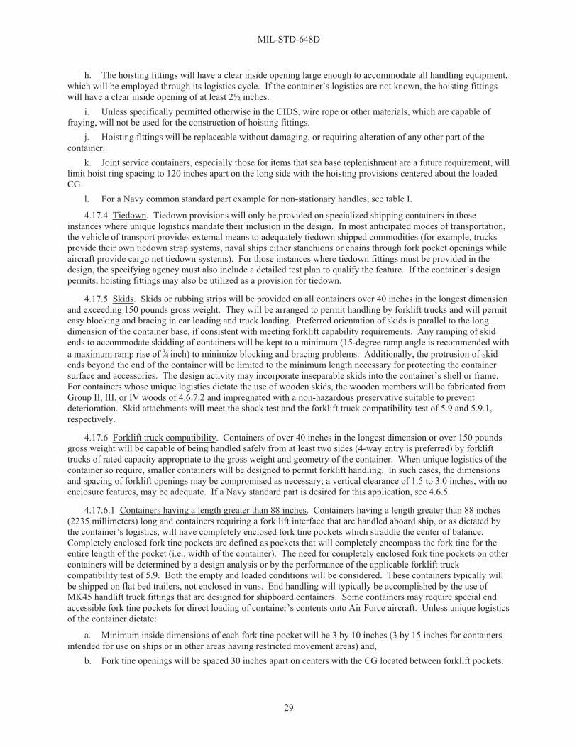
MIL-STD-648D
29
h. The hoisting fittings will have a clear inside opening large enough to accommodate all handling equipment, which will be employed through its logistics cycle. If the container’s logistics are not known, the hoisting fittings will have a clear inside opening of at least 2½ inches.
i. Unless specifically permitted otherwise in the CIDS, wire rope or other materials, which are capable of fraying, will not be used for the construction of hoisting fittings.
j. Hoisting fittings will be replaceable without damaging, or requiring alteration of any other part of the container.
k. Joint service containers, especially those for items that sea base replenishment are a future requirement, will limit hoist ring spacing to 120 inches apart on the long side with the hoisting provisions centered about the loaded CG.
l. For a Navy common standard part example for non-stationary handles, see table I.
4.17.4 Tiedown. Tiedown provisions will only be provided on specialized shipping containers in those instances where unique logistics mandate their inclusion in the design. In most anticipated modes of transportation, the vehicle of transport provides external means to adequately tiedown shipped commodities (for example, trucks provide their own tiedown strap systems, naval ships either stanchions or chains through fork pocket openings while aircraft provide cargo net tiedown systems). For those instances where tiedown fittings must be provided in the design, the specifying agency must also include a detailed test plan to qualify the feature. If the container’s design permits, hoisting fittings may also be utilized as a provision for tiedown.
4.17.5 Skids. Skids or rubbing strips will be provided on all containers over 40 inches in the longest dimension and exceeding 150 pounds gross weight. They will be arranged to permit handling by forklift trucks and will permit easy blocking and bracing in car loading and truck loading. Preferred orientation of skids is parallel to the long dimension of the container base, if consistent with meeting forklift capability requirements. Any ramping of skid ends to accommodate skidding of containers will be kept to a minimum (15-degree ramp angle is recommended with a maximum ramp rise of 3⁄4 inch) to minimize blocking and bracing problems. Additionally, the protrusion of skid ends beyond the end of the container will be limited to the minimum length necessary for protecting the container surface and accessories. The design activity may incorporate inseparable skids into the container’s shell or frame. For containers whose unique logistics dictate the use of wooden skids, the wooden members will be fabricated from Group II, III, or IV woods of 4.6.7.2 and impregnated with a non-hazardous preservative suitable to prevent deterioration. Skid attachments will meet the shock test and the forklift truck compatibility test of 5.9 and 5.9.1, respectively.
4.17.6 Forklift truck compatibility. Containers of over 40 inches in the longest dimension or over 150 pounds gross weight will be capable of being handled safely from at least two sides (4-way entry is preferred) by forklift trucks of rated capacity appropriate to the gross weight and geometry of the container. When unique logistics of the container so require, smaller containers will be designed to permit forklift handling. In such cases, the dimensions and spacing of forklift openings may be compromised as necessary; a vertical clearance of 1.5 to 3.0 inches, with no enclosure features, may be adequate. If a Navy standard part is desired for this application, see 4.6.5.
4.17.6.1 Containers having a length greater than 88 inches. Containers having a length greater than 88 inches (2235 millimeters) long and containers requiring a fork lift interface that are handled aboard ship, or as dictated by the container’s logistics, will have completely enclosed fork tine pockets which straddle the center of balance. Completely enclosed fork tine pockets are defined as pockets that will completely encompass the fork tine for the entire length of the pocket (i.e., width of the container). The need for completely enclosed fork tine pockets on other containers will be determined by a design analysis or by the performance of the applicable forklift truck compatibility test of 5.9. Both the empty and loaded conditions will be considered. These containers typically will be shipped on flat bed trailers, not enclosed in vans. End handling will typically be accomplished by the use of MK45 handlift truck fittings that are designed for shipboard containers. Some containers may require special end accessible fork tine pockets for direct loading of container’s contents onto Air Force aircraft. Unless unique logistics of the container dictate:
a. Minimum inside dimensions of each fork tine pocket will be 3 by 10 inches (3 by 15 inches for containers intended for use on ships or in other areas having restricted movement areas) and,
b. Fork tine openings will be spaced 30 inches apart on centers with the CG located between forklift pockets.

MIL-STD-648D
30
NOTE: 1/ Twenty-eight inches if Rough Terrain Trailer interface is also required.
FIGURE 2. Standard fork tine spacings.
4.17.6.2 Containers ranging in length from 50 to 88 inches. Containers ranging in length from 50 to 88 inches should have partially enclosed fork tine pockets on each side of the container. Partially enclosed fork tine pockets are defined as pockets that will completely encompass the fork tine at both the entry and exit locations (both container sides) yet remain unenclosed on its bottom in the central section of the container to allow for pallet jack wheel usage. Each of the enclosed fork tine areas must be structurally sound to withstand the input forces associated with all handling logistics. Size and spacing should accommodate either long containers as defined above, or for pallet size containers, defined below.
4.17.6.3 Pallet size containers (52 by 44 inches or smaller). Pallet size containers (52 by 44 inches or smaller) should be 4-way fork tine entry compatible where possible. Partially enclosed fork tine pockets should be designed into the long side of the container. Open or partially enclosed fork tine pockets should be designed into the short side of the container to allow for pallet jack wheel usage. For the long side, pallet jack compatibility to SAE AS5389 is desirable if it does not add significant cost to the design.
FIGURE 3. Pallet size container fork tine spacings.

MIL-STD-648D
31
4.17.6.4 Direct interface with military aircraft loading operations. In unique instances, containers may be required to directly interface with military aircraft loading operations. The backbone of aircraft loading operations is the Air Force’s 463L cargo system, which is comprised of a: pallet, nets, MHE, and aircraft rail/roller systems. Overall dimensions of the 463L pallet are 88 by 108 inches, with usable dimensions of 84 by 104 inches. This allows 2 inches around the load to attach straps, nets, or other restraint devices. Containers possessing flat bottoms, that are to be transported almost exclusively by air shipment, will be handled by long fork lift tines underneath the container on approximately 48-inch centers. These containers will have to be placed on wood supports while awaiting loading. Fully enclosed fork lift tine pockets should be incorporated in these types of containers that will be moved by other methods of transportation. These fork tine pockets may be on 48-inch centers and possess the standard fork tine opening of 3 by 15 inches. For additional information on the 463L, see MIL-HDBK-1791.
4.17.6.5 Secondary uses for fork pockets. If the container fork tine pockets are to be used for unitizing or tiedown, special consideration should be given to the loads and forces which are involved. If the fork pockets are to be used for creating a unit load by use of steel strapping through the fork pockets, then the top and bottom edge of each opening of the fork pockets must be either beveled or rounded to prevent sharp creasing of the strapping during tensioning. The maximum inside-to-inside dimensions will be 20 inches. If a Navy standard part is desired for this application, see the references for fork pockets in 4.6.5. SAE AS5389 may be used for additional information on container fork pocket interfaces.
4.17.7 Shipboard handling. Containers of over 300 pounds gross weight or 3 feet long and without 4-way fork tine entry or longer, which are intended to be end handled by mechanical means aboard combatant or auxiliary Naval ships, will have special provisions for handling and stowage in confined and limited-access stowage areas as follows:
a. A metallic fitting will be provided at each end of the container to permit handling with the Handlift Truck, MK 45, all MODs. Each container fitting will be capable of supporting three times the maximum weight, including fleet issue unit loads, if applicable, that it is required to support. The fittings will be located as shown on NAVSEA Drawing 6214131 (see Appendix B). The container structure will be sufficiently stiff to permit a minimum clearance of 3 inches between the bottom of the container and a level deck, along the container's entire length, with the Handlift Truck in its fully elevated position, and when tested in the configuration in which it will be used (for example, with or without cover applied). The fitting and container structure will meet the strength requirements of the tests described in 5.10. If a Navy standard part is desired for this application, see the references for endlift extrusion and endlift-adapter in 4.6.5.
b. Where appropriate, containers handled and stowed on aircraft carriers will have provisions to permit overhead handling of a loaded container at the center of balance by utilizing the HLU-2l6/E Beam shown on NAVAIR Drawing 616856, HLU-216A/E Beam shown on NAVAIR Drawing 616856-3, or the MK 52 MOD 0 Beam shown on NAVSEA Drawing 6212876. The provisions, or “lift arms”, will be designed to be capable of supporting three times the maximum weight that it is required to support. Fleet issue unit loads are not to be lifted by the HLU-2l6/E, HLU-2l6A/E, or MK 52 MOD 0. Only single containers are to be handled by these handling beams. The lift arms will not protrude beyond the container’s envelope when not in use. Provisions will be made to allow for stacking of like containers in both the forward-to-forward or forward-to-aft configurations with the lift arms in their up position, unless the lift arms are designed to slide vertically into the cover’s wall while remaining recessed and accessible without the use of tools. Wire rope or other materials, which are capable of fraying, will not be used for the construction of lift arms. If a Navy standard part is desired for this application, see the references for center lift in 4.6.5.
c. For containers that will be opened in Navy ship’s magazines, possessing covers weighing in excess of 75 pounds, the cover will be designed with a cover lift provision that interfaces with the shipboard hoist. This provision will be clearly marked, “FOR COVER LIFT ONLY” if it does not possess adequate capacity to lift the entire container fully loaded. Unless specifically permitted otherwise, wire rope or other materials that are capable of fraying will not be used in the design. If a Navy standard part is desired for this application, see the references for center lift in 4.6.5.
4.17.8 Handling provision maintainability. Handling provisions will be designed as much as possible to be readily repairable and replaceable without damaging, or requiring alteration of any other part of the container.

MIL-STD-648D
32
4.18 Special protection devices.
4.18.1 Temperature control. Special provisions for controlling or limiting the extremes of temperature within a container will be avoided. In those cases where such provisions may be justified and specifically required by the design activity, they will be as simple and as lightweight as possible and meet all the performance requirements of this standard. Detailed design requirements will be established on a case-by-case basis by the design activity by consideration of the thermal properties of the item to be protected and the temperature environment in which it must survive.
4.18.2 Field-force protection. When the contained item is susceptible to damage from electrostatic, electromagnetic, magnetic, microwave, radio frequency, or radioactive forces during handling, shipment, and storage, the container will be designed to provide the required protection from the appropriate field-force, as specified by the design activity.
4.18.3 Magnetic shielding. For packaging and transportation purposes, magnetic items may be handled as non-magnetic material when the maximum field strength at a distance of 7 feet from the package of the item is 0.002 gauss or less. However, items in this category, when consolidated, may exceed the 0.002 gauss limitation and la-beling or shielding may be required. When the magnetic field strength of an item exceeds 0.002 gauss at 7 feet, but does not exceed 0.00525 gauss at 15 feet, labeling only will be required. Containers for items, which are considered to possess a magnetic field strength exceeding 0.00525 gauss when measured at a distance of 15 feet from any face of the packaged item, and which may be shipped by air, will be provided with appropriate shielding. Adequacy of shielding will be determined in accordance with 5.12.
4.19 Protecting and identifying the container.
4.19.1 Painting requirements. Painting, when required, will be as specified by the design agent and will meet Occupational Safety and Health Administration (OSHA) and Environmental Protection Agency (EPA) guidelines. Painting will be primarily required for Nuclear, Biological, and Chemical (NBC) survivability, corrosion pre-vention, or to provide camouflage. Interior surfaces of closed painted containers need be painted with primer only. Where the contents incorporate plated hardware (see 4.6.1), the primer will be of a synthetic type known to be compatible with the plating in use. The specific color and paint grade, required for exterior top coats, will be as indicated by the design activity. CARC requirements will be defined by the using agency.
4.19.2 Identification and instructional markings.
4.19.2.1 Identification marking. Fully reusable containers will be identified in accordance with MIL-STD-130, unless otherwise specified by the design activity. When the name of the contents is classified, the permanent identification will include only the approved nomenclature (for example, MK and MOD number, Container Numerical Unit (CNU) number), and National Stock Number (NSN) of the container. Shipping containers will be compatible with Automatic Identification Technology (AIT), Radio Frequency Identification (RFID), and Unique Identification (UID) policies as contained in the Under Secretary of Defense (USD) Acquisition, Technology & Logistics (AT&L) Memorandum Radio Frequency Identification Policy (http://www.dodrfid.org), and the USD (AT&L) Memorandum Update to Unique Identification (http://www.acq.osd.mil/dpap/sitemap.html). Provisions must be taken to ensure that AIT components do not violate HERF/HERO/HERP standards.
4.19.2.2 Basic instructional markings. Markings on shipping containers will be permanent and legible for the life of the container in the defined logistics environments and will include all basic instructional and operating caution markings required for safe, expeditious handling, and use of the container. Markings will include, but will not be limited to, as applicable:
a. Center of balance b. ESD sensitive contents c. Forklift and stacking points d. Identification of any special sling needed e. Records receptacle f. Desiccant receptacle

MIL-STD-648D
33
g. Pressure relief valve(s) h. Humidity indicator i. Hoisting and tiedown attachment points j. Warning notes k. Instructions for opening, closing, and repressurizing the container l. AFT m. Cover lift n. FWD o. Lift arm p. Observation window q. Reusable container—do not destroy
4.19.2.3 Color coding. Space will be reserved (5 by 8 inches, if possible) on each end of ammunition containers (except for small arms ammunition containers) for applying color coding and identification markings, in accordance with MIL-STD-709, unless otherwise specified in the CIDS.
4.19.3 Container markings. Provisions, along with an identified placement location, will be incorporated into the design for applying container markings and bar coding(s), in accordance with MIL-STD-129, unless otherwise specified in the CIDS.
4.20 Nuclear, biological, chemical (NBC) survivability. Containers used to package mission-essential items that may encounter an NBC environment will be designed of materials that meet the following criteria:
a. Selection of non-metallic materials used in the construction/fabrication of containers will be chemical agent decontaminable to acceptable levels as specified in the U.S. Army Nuclear and Chemical Agency (USANCA) criteria and AR 70-71 when tested in accordance with TOP 8-2-111.
NOTE: The USANCA criteria and any questions pertaining therein may be addressed to the Mission Sustainment and Survivability Division, ATTN: SMCCA-OP, at the U.S. Army Chemical Research, Development and Engineering Center, Aberdeen Proving Grounds, MD 21010-5423.
b. For metallic materials, application of a CARC will be applied in accordance with MIL-DTL-53072. c. Container design will be such that overall configuration will minimize contamination by NBC agents
and facilitate effective decontamination to the maximum possible extent in view of the container’s specific cost and functional restrictions imposed.
4.21 Human systems integration (HSI). HSI aspects shall be considered in the design of specialized shipping containers. HSI design specifications, as found in ASTM F1166 and MIL-STD-1472, will be used in the design of labels, handles/grasp areas, fasteners, covers, and hoisting/carrying devices. HSI considerations include, but are not limited to:
a. Human factors engineering. The application of knowledge about human capabilities and limitations to system or equipment design assures that the system or equipment design, required human tasks, and work environment are compatible with the sensory, perceptual, mental, and physical attributes of personnel who will operate, maintain, control, and support the system or equipment. Location and size of equipment will assure easy operation and maintenance by personnel in 5th – 95th percentile or other defined (expected) population.
b. Safety and health. Safety and health factors are those system design features that serve to minimize the risk of injury, acute or chronic illness or disability; or reduce job performance of personnel who operate, maintain, or support the system. Prevalent issues include noise, chemical safety, atmospheric hazards, vibration, ionizing and non-ionizing radiation, and repetitive stress injuries.
c. Manpower, personnel, and training. The number of trained personnel required to operate, maintain, and support system equipment in its operational environment requires consideration of the user population and the knowledge, skills, and abilities (KSAs) required by the intended user to effectively and safely operate, maintain, and support the system.

MIL-STD-648D
34
d. Personnel survivability. Considerations include the development and use of personnel protective equipment, such as required clothing and gear necessary to effectively and safely operate, maintain, and support the system.
4.22 Pallet jack compatibility. For containers possessing forklift truck provisions that are also required to be moved by pallet jacks, provisions must be made to allow for pallet jack interface capability. SAE AS5389 may be used for additional information on container pallet jack interfaces.
5. DETAILED REQUIREMENTS
5.1 Fit and compatibility.
5.1.1 General. The container will be designed to be compatible with the contained item. It will permit easy loading, movement, and unloading. It will be compatible with the normal logistic patterns for its contents, as well as with any special requirements which are specified design constraints. The container will be designed so that the intended load will fit securely but without interference or binding. It will support and restrain the item at points and by methods which are not likely to result in damage due to careless manipulation or handling. Loading and unloading will be a simple process by the normal handling equipment intended to be available at the points of use. Each test is considered to be a unique individual event. As such, during qualification testing, the container’s isolation system may be replaced after each test event.
5.1.2 Fit test. This test will be conducted by bringing together the container and the intended load. The load will be placed in position in the container and the container will be assembled in its normal shipping condition by fitting the cover, fastening all restraining devices, placing desiccant, and otherwise completely securing the container for shipment. If the container possesses installation instructions, they will take precedence over any other loading sequence, and will be followed to verify fit when performing both the loading and unloading sequence. The container is then unloaded. Only the normal handling equipment likely to be available at points of loading and unloading may be used. Care will be exercised to assure that both the container and the load are representative of the final configuration and that normal dimensional variations are considered. A lack of “fit” or extreme awkwardness during the necessary loading and unloading process is cause for rejection. Loading and unloading times will be recorded if such times are a specified design constraint. Not meeting specified loading or unloading times with the specified number of appropriately qualified personnel will be cause for rejection.
5.2 Mechanical shock.
5.2.1 General. Containers will be designed to protect the contents from damage resulting from exposure to applicable shock tests described herein. Tests will be selected from 5.2.2 through 5.2.11, as applicable, or as specified by the design activity. Shock tests will be at the Level A severity unless otherwise specified in the CIDS. When the container’s design requirements mandate that it be carried by hand, ergonomics may be allowed to dictate the qualification test drop heights. Anthropometry data may be used to determine these heights. The qualification drop height in these instances will equal the average palm grip elevation above floor level minus distance from the container’s handle elevation in the carrying position to the lowest position of the container’s shell.
5.2.1.1 Acceptance criteria. The function of a container will not be significantly impaired by the shock tests, except as specifically noted. Evidence of one or more of the following will be cause for rejection:
a. Damage to the contents. Such damage may be established by either functional tests or other specific evidence of sensitivity to the test conditions.
b. Failure of the container’s energy absorbing devices to protect the contents to the fragility level established as a design constraint by the equipment designer.

MIL-STD-648D
35
NOTE: Shock Response Spectrum (SRS) analysis is the preferred method for analysis of shock data. IEST-RD-DTE012.2 is a good source for information on Dynamic Data Acquisition and Analysis. In the absence of specific frequency information, it is assumed that only those frequency components under 10 times the natural frequency of the shock isolation system are damaging. As such, prior to actual SRS analysis, all time history data shall be filtered at no less than 15 times the natural frequency of the isolation system with a linear phase filter. Improper filtering can result in corruption of data. The SRS analysis will then be performed to 10 times the natural frequency of the isolation system’s natural frequency. In those cases where SRS analysis is not required, time history data will be filtered no less than 10 times the natural frequency with a linear phase filter. Unless otherwise specified in the CIDS, shock response spectrum analysis shall be performed using a damping factor of 0.05.
c. Failure of a water vapor or water proof container to prevent water vapor transmission or water leakage within the specified limits given in 5.6.2.1.
d. Failure of the container to retain the contents. e. Failure of the container to permit continued safe handling. f. Loosening of restraining material or devices which may permit the contents to be damaged if further
handling is experienced. g. Permanent deformation of any portion of the container that affects its functional performance throughout
the anticipated logistic cycle. h. Evidence of the contents striking the container walls, unless it can be shown that such contact does not
degrade performance of the item being packaged.
NOTE: Weld cracks in other than principal load paths, which do not result in rejection as stipulated above, and are repairable, will not be cause for rejection.
5.2.1.2 Test loads. Operable articles will be used, wherever possible, during the container development and evaluation phase. These articles will be completely representative of the container’s intended contents with the exception that any explosive or hazardous material is to be replaced by inert materials of equivalent mass properties. In the event that operable articles are not available, then test loads, such as Dynamic/Dimensional Inert Missiles (DIMs) or Inert Operational Shapes (IOSs) may be used if the prime contractor agrees that it is a valid representative test shape. As a minimum, the test load’s characteristics will as closely as possible represent those of the object being simulated (within the tolerance envelope of the real operable article) as follows:
a. Envelope dimensions including external features, such as safing pins, antennas, and lanyards, which may have a bearing on the package design.
b. Mounting points or external hard zone area geometry and strength (i.e., bending and shear moment along the operable article’s entire length, skin thicknesses representing soft zones, etc.).
c. Surface finishes which require special handling provisions. d. Weight, CG, and radii of gyration in the three principal axes. e. Internal joints and shock mounts identical to the operable article. f. Identified stations where fragility readings are critical and allowable levels of fragility at those locations. g. For operable articles which possess electronic systems, operable electronics within the shape that possess
Built In Test (BIT) features that are to be queried prior to and upon completion of testing.
5.2.1.3 Instrumentation. When required, the test load will be suitably instrumented, and data will be collected during testing to assure that established fragility levels are not exceeded. Unless otherwise specified in the CIDS, shock time histories (Gs vs. time) in the major directions will be recorded on the test load at: hard zones near the CG, hard zones near the extremities, or at zones where the fragility is clearly defined. The recorded shock histories will then be reduced into shock spectra plots as a means of supplying additional information for evaluation of the isolation system. For uniquely configured or irregularly-shaped items, and in cases where known fragility points have not been established, engineering judgment will be used in selecting instrumentation locations.

MIL-STD-648D
36
5.2.1.4 Temperature combined with shock. Container designs using materials, which may be affected by temperature variations, will be subjected to the shock tests of this section, except as noted, at the extreme temperatures which may be expected in service. Table IV contains a guideline for expected temperature extremes. At the discretion of the design activity, a single container may be required to survive tests at the required temperature extremes. In such cases, wherever possible, the impact points will be at locations not previously impacted. When required by the design activity, ambient testing will also be performed.
TABLE IV. Expected temperature extremes.
Minimum extremes for all containers
Typical extremes for ground troop usage
-20±5 °F -65±5 °F+120±5 °F1/ +160±5 °F
NOTE: 1/ For desert stowage use +140±5 oF.
5.2.1.5 Drop surface recommendation. The drop surface will be a minimum of 3 inches (75 millimeters) thick flat smooth steel plate, level to within 2 degrees of horizontal possessing a Brinell hardness of 200-311 and be a minimum of 10 feet (3 meters) in length on each side. The steel plate will be uniformly supported throughout by a minimum thickness of 2 feet (60 cm) of reinforced 4,000 PSI (28 MN/m2) concrete or stronger. The steel plate will be of sufficient area to ensure that a dropped test item(s), including rebound(s), will be retained within its surface area. The drop test facility shall be constructed such that no free water is retained on top of the steel plate. Any ice or debris will be removed from the impact surface prior to testing. Various guidance systems that do not reduce the impact velocity may be employed to ensure the impact angles; however, any guidance system will be eliminated at a sufficient height above the impact surface to allow unimpeded fall and rebound. It is recommended that the equipment is checked at regular intervals for any degradation in its ability to provide a consistent, repeatable impact surface relevant to maximum weight and size of the test item(s). Existing drop test facilities consisting of concrete, faced with steel plate, with a foundation effectively 20 times the mass of the item being tested may be used for this test; however, construction of new facilities should be in accordance with the requirements above. It is desirable that these facilities be constructed as soon as possible to ensure standardization of test facilities.
5.2.2 Repetitive shock test. This test will be conducted in accordance with Appendix F, if circular input motion is used, table frequency will be adjusted to assure that one edge of the container leaves the table not less than 1⁄16 inch on each cycle. This test is normally conducted at an ambient temperature. For containers possessing shock mounts, the temperature of the resilient mounts should not be allowed to exceed the safe operating temperature of the elastomer. Army munition containers issued to ground troops will be tested in accordance with MIL-STD-1904 or MIL-STD-810 Method 514, Category 5, Loose Cargo at the three temperatures (-65 °F, ambient, 160 °F) specified in 5.2.1.4. As an alternate, ASTM D999, Method A1 or A2, as applicable, may be used as an acceptable test method.
5.2.2.1 Repetitive shock test (stacked). This test will be conducted as specified in 5.2.2 except for the following:
a. The containers will be tested two layers high unless it has been designed to be shipped in a unit load configuration that exceeds two containers in height. In that instance, the stacked test will be comprised of two unit loads stacked one atop the other.
b. The distance the upper container lifts from the lower container will be measured. c. If the containers to be tested are normally shipped rigidly joined together in a stacked configuration (for
example, strapped or latched together), then the distance to be measured will be taken between the lower container’s base and input table.

MIL-STD-648D
37
5.2.3 Drop test (free-fall). This test will be conducted in accordance with Appendix G. Procedure D will be used for cylindrical containers. Procedure G will be used for rectangular containers. Level A protection will be used unless otherwise specified in the CIDS. Army munition containers issued to ground troops will be 3- and 7-foot free-fall drops tested in accordance with MIL-STD-1904 at the three temperatures (-65 °F, ambient, 160 °F) specified in 5.2.1.4. As alternate, ASTM D5276 may be used as an acceptable test method. Drop heights from Appendix G may be used with this alternate test method, or at the option of the design agency, a more representative drop test height, which duplicates the maximum potential drop expected for a special shipping container during its normal service life, may be substituted in lieu of the value found in table G-I. As a guideline for normal handling and transportation mishaps of non-person portable containers for Level A protection, 15 inches is an acceptable height, while for Level B protection, 12 inches is an acceptable height regardless of overall gross weight or dimensional size. For person portable containers, the anthropometry guidelines in 5.2.1 may be used to establish the drop heights. As an alternate, when appropriate, ITOP 4-2-601 and ITOP 4-2-602 may be used as acceptable test methods.
5.2.4 Cornerwise-drop (rotational) test. This test will be conducted in accordance with Appendix H. Level A protection will be used unless otherwise specified in the CIDS. At the option of the design agency, a more representative drop test height, which duplicates the maximum potential drop expected for a special shipping container during its normal service life, may be substituted in lieu of the value found in table H-I. As a guideline, for normal handling and transportation mishaps of non-person portable containers for Level A protection, 15 inches is an acceptable height while for Level B protection, 12 inches is an acceptable height regardless of overall gross weight or dimensional size. For containers whose isolation systems restrict load shifting, when symmetry permits, these tests should be conducted in accordance with figure 4 and table V to prevent generation of redundant data. Army munition containers issued to ground troops will be tested in accordance with MIL-STD-1904 at the three temperatures (�65 °F, ambient, 160 °F) specified in 5.2.1.4.
5.2.5 Edgewise-drop (rotational) test. This test will be conducted in accordance with Appendix I. Level A protection will be used unless otherwise specified in the CIDS. At the option of the design agency, a more representative drop test height, which duplicates the maximum potential drop expected for a special shipping container during its normal service life, may be substituted in lieu of the value found in Appendix I, table I-I. As a guideline, for normal handling and transportation mishaps of non-person portable containers for Level A protection, 15 inches is an acceptable height while for Level B protection, 12 inches is an acceptable height regardless of overall gross weight or dimensional size. For containers whose isolation systems restrict load shifting, when symmetry permits, these tests should be conducted in accordance with figure 4 and table V to prevent generation of redundant data. Army munition containers issued to ground troops will be tested in accordance with MIL-STD-1904 at the three temperatures (-65 °F, ambient, 160 °F) specified in 5.2.1.4.
5.2.6 Tipover test. The tipover test will be performed in accordance with Appendix J if the container and content weight and balance are such that the container will tip over when an edge or corner is raised sufficiently for the base to form a 20-degree angle with the floor. At the option of the design activity, the rollover test, Appendix K, may be substituted for this test. Army munition containers issued to ground troops will be tested in accordance with MIL-STD-1904 at the three temperatures (�65 °F, ambient, 160 °F) specified in 5.2.1.4.
5.2.7 Impact test. This test will be conducted in accordance with either the procedures of Appendix L (incline-impact test) or Appendix M (pendulum-impact test). Impact velocity will be 5 feet/second. For containers whose isolation systems restrict load shifting, when symmetry permits, these tests should be conducted in accordance with figure 4 and table V to prevent generation of redundant data. Army munition containers issued to ground troops will be tested in accordance with MIL-STD-1904 at the three temperatures (-65 °F, ambient, 160 °F) specified in 5.2.1.4. As an alternate, ASTM D880 may be used as an acceptable test method.

MIL-STD-648D
38
FIGURE 4. Samples of symmetrical packaging.
TABLE V. Mechanical shock input locations to containers.
Single pack Dual pack
Corner Edge Impact1/ Corner Edge Impact
Hot Cold Hot Cold Hot Cold Hot Cold Hot Cold Hot Cold
C1 E1 E1 E1 E1 C1 E1 E1 C2 E2 E2 C2 E2 E2
C3 E3 E3 E3 E3 C3 E3 E3 C4 E4 E4 C4 E4 E4
Triple pack Quad pack
Corner Edge Impact Corner Edge Impact
Hot Cold Hot Cold Hot Cold Hot Cold Hot Cold Hot Cold
C1 E1 E1 C1 E1 E1 C2 E2 E2 C2 E2 E2
C3 E3 E3 C3 E3 E3 C4 E4 E4 C4 E4 E4
NOTE: 1/ For multi-packs that are all oriented in the same direction, use the single pack impact
locations.
5.2.7.1 Impact test (stacked). Containers likely to be stacked and shipped by railcar or flatbed trailer will be subjected to this test. The procedure will be identical to that of the impact test of 5.2.7, except that the containers will be stacked in the normal shipping configuration (typically two high). Dummy contents may be used. Containers likely to be stacked and shipped by railcar will be subjected to one impact on each end of the bottom container at 11.7 feet/second. Containers likely to be stacked and shipped by flatbed trailers only will be designed to pass one impact on each end of the bottom container at 5 feet/second. Evidence of failure of the connecting structures which would permit any of the containers to become unattached will be cause for rejection. In lieu of the
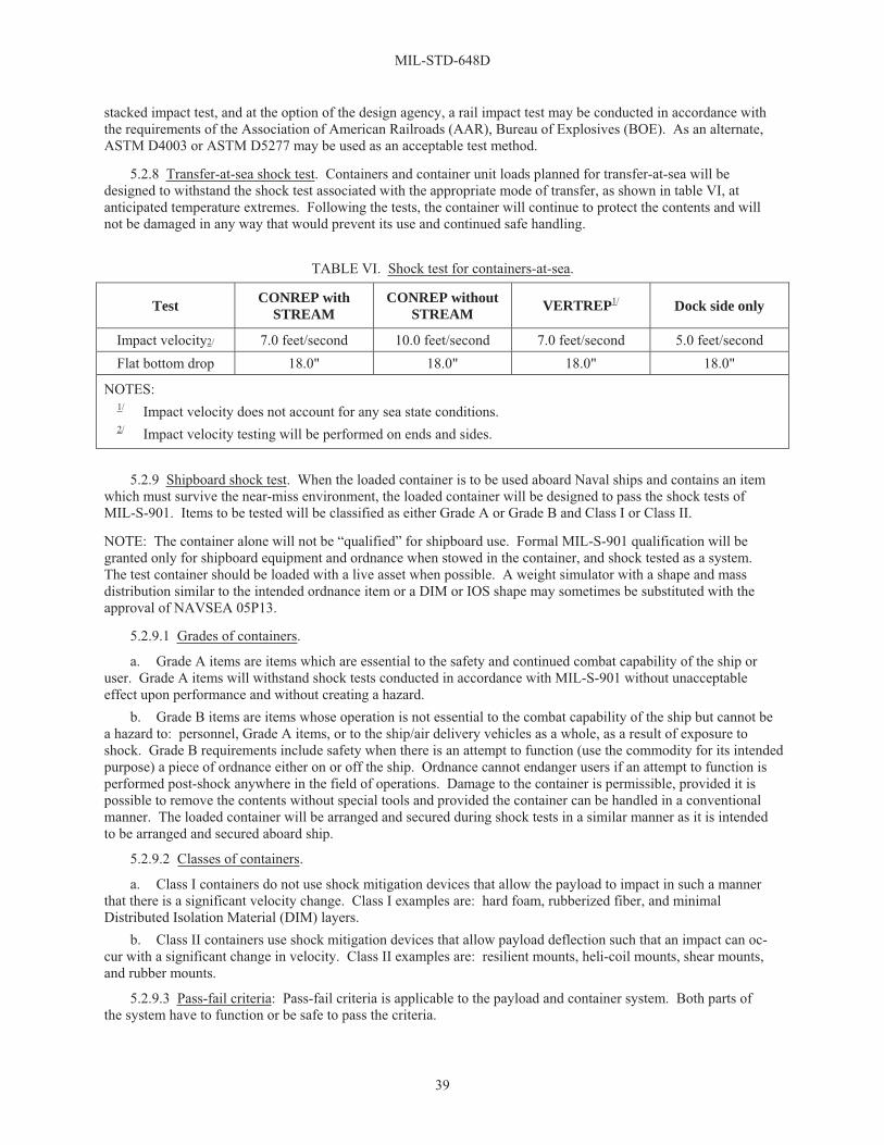
MIL-STD-648D
39
stacked impact test, and at the option of the design agency, a rail impact test may be conducted in accordance with the requirements of the Association of American Railroads (AAR), Bureau of Explosives (BOE). As an alternate, ASTM D4003 or ASTM D5277 may be used as an acceptable test method.
5.2.8 Transfer-at-sea shock test. Containers and container unit loads planned for transfer-at-sea will be designed to withstand the shock test associated with the appropriate mode of transfer, as shown in table VI, at anticipated temperature extremes. Following the tests, the container will continue to protect the contents and will not be damaged in any way that would prevent its use and continued safe handling.
TABLE VI. Shock test for containers-at-sea.
Test CONREP with STREAM
CONREP without STREAM VERTREP1/ Dock side only
Impact velocity2/ 7.0 feet/second 10.0 feet/second 7.0 feet/second 5.0 feet/secondFlat bottom drop 18.0" 18.0" 18.0" 18.0"
NOTES: 1/ Impact velocity does not account for any sea state conditions. 2/ Impact velocity testing will be performed on ends and sides.
5.2.9 Shipboard shock test. When the loaded container is to be used aboard Naval ships and contains an item which must survive the near-miss environment, the loaded container will be designed to pass the shock tests of MIL-S-901. Items to be tested will be classified as either Grade A or Grade B and Class I or Class II.
NOTE: The container alone will not be “qualified” for shipboard use. Formal MIL-S-901 qualification will be granted only for shipboard equipment and ordnance when stowed in the container, and shock tested as a system. The test container should be loaded with a live asset when possible. A weight simulator with a shape and mass distribution similar to the intended ordnance item or a DIM or IOS shape may sometimes be substituted with the approval of NAVSEA 05P13.
5.2.9.1 Grades of containers.
a. Grade A items are items which are essential to the safety and continued combat capability of the ship or user. Grade A items will withstand shock tests conducted in accordance with MIL-S-901 without unacceptable effect upon performance and without creating a hazard.
b. Grade B items are items whose operation is not essential to the combat capability of the ship but cannot be a hazard to: personnel, Grade A items, or to the ship/air delivery vehicles as a whole, as a result of exposure to shock. Grade B requirements include safety when there is an attempt to function (use the commodity for its intended purpose) a piece of ordnance either on or off the ship. Ordnance cannot endanger users if an attempt to function is performed post-shock anywhere in the field of operations. Damage to the container is permissible, provided it is possible to remove the contents without special tools and provided the container can be handled in a conventional manner. The loaded container will be arranged and secured during shock tests in a similar manner as it is intended to be arranged and secured aboard ship.
5.2.9.2 Classes of containers.
a. Class I containers do not use shock mitigation devices that allow the payload to impact in such a manner that there is a significant velocity change. Class I examples are: hard foam, rubberized fiber, and minimal Distributed Isolation Material (DIM) layers.
b. Class II containers use shock mitigation devices that allow payload deflection such that an impact can oc-cur with a significant change in velocity. Class II examples are: resilient mounts, heli-coil mounts, shear mounts, and rubber mounts.
5.2.9.3 Pass-fail criteria: Pass-fail criteria is applicable to the payload and container system. Both parts of the system have to function or be safe to pass the criteria.

MIL-STD-648D
40
5.2.9.4 Class I containers (foam or rubberized fiber isolation systems). Mitigation of a shock event is achieved by the compressing isolation material, which reduces the velocity of the packaged item. As the isolation material compresses it becomes nonlinearly harder and harder to compress. The isolation system will be located between the packaged item and the container’s walls. The container’s contents will not be imparted a sudden complex hi-shock, as long as the packaged item is not allowed to contact the container’s walls.
5.2.9.4.1 Container testing. These types of containers may be able to be tested on the Medium Weight Shock Machine (MWSM), Light Weight Shock Machine (LWSM), or Floating Shock Platform (FSP), if within the general MIL-S-901 guidelines.
5.2.9.4.2 Weight limitations. If eligible for MWSM testing, the maximum allowable weight on the MWSM is 7,400 pounds. Standard fixturing for inclined testing effectively limits the maximum loaded container weight to 5,000-5,500 pounds depending on specific fixture design. Also, the foam isolation system cannot have a deflection capability in excess of 3 inches in any direction.
5.2.9.4.3 Size limitations. Containers tested on the MWSM should not exceed practical size limitations. Containers using the MWSM cannot use shock mitigation, which allows bottoming of the payload (such systems are considered MIL-S-901 Class II).
5.2.9.4.4 Testing orientations. Containers tested on the MWSM should be subjected to testing in three distinct orientations. One (1) level and two (2) in different inclined orientations for a total of nine blows, as suggested by MIL-S-901 (see 3.1.6.2.3) for items oriented in different directions aboard ship.
5.2.9.4.5 Method of securing the container to the MWSM. Whenever possible, the method of securing the container to the MWSM should be the same as that used aboard ship. When using hi-shock chains, the setup should account for chain angle, length, and quantity. Another similar container or containers will be placed on top of the test unit as a fixture.
5.2.9.4.6 Design criteria. If a new fixture needs to be designed, it should be in accordance with MIL-S-901 guidelines (no yielding, etc.). Fixture frequency for the MWSM should also be part of the design criteria (nominal 25 hertz without other guidance). If the size of the container precludes the use of shipboard securing methods on the MWSM, it is permissible to use a clamping bar arrangement with NAVSEA 05P13 concurrence.
5.2.9.4.7 Floating shock platform (FSP testing). If not eligible for LWSM or MWSM testing, then FSP testing is required.
5.2.9.4.8 Heavyweight shock test. If the LWSM or MWSM cannot be used due to criteria violations, the test item is to be subjected to a heavyweight shock test on the FSP.
5.2.9.4.9 Deck-stowed containers. Deck-stowed containers using mitigation systems, which do not allow bottoming, should be tested on an FSP with a nominal 25-hertz deck, unless otherwise directed by NAVSEA 05P13.
5.2.9.4.10 Method of securing the container to the FSP. The method of securing the container to the FSP should be the same as that used aboard ship. When using hi-shock chains, the setup should account for chain angle, length, and quantity. Another similar container or containers will be placed on top of the test unit as a fixture.
5.2.9.4.11 Chain tiedown assembly. Containers are secured to deck cargo holds using a hi-shock chain tiedown assembly or blocked using stanchions. These methods of securing do not attach containers rigidly to the ship decks like other isolated shipboard equipment (for example, computer consoles are bolted directly to ship’s deck). The chain tiedown assembly consists of a shock mitigator, steel forged connecting link, chain, and tensioner (over center latch-type with automatic lever lock, steel forged deck fitting, and a special forged hook keeper). The use of chain tiedown assemblies greatly circumvents the energy transfer of the deck’s natural frequency during a hi-shock event.
5.2.9.5 Class II containers (resilient mount isolation systems). Deck-stowed items using mitigation systems, which would allow bottoming, should be tested on a FSP with a nominal 12- to 16-hertz deck, unless otherwise directed by NAVSEA 05P13. The method of securing the container to the FSP should be the same as that used aboard ship. When using hi-shock chains, the setup should account for chain angle, length, and quantity. Another similar container or containers will be placed on top of the test unit as a fixture.

MIL-STD-648D
41
5.2.9.5.1 Testing to hi-shock events. When tested to hi-shock events, resilient mount isolation systems might allow the container’s contents, or cradle system holding the contents, to exceed the available sway space in the container. This could result in the packaged item, or cradle, contacting the inside walls of the container, producing a complex hi-shock event.
5.2.9.5.2 Chain tiedown assembly. Containers are secured to deck cargo holds using a hi-shock chain tiedown assembly or blocked using stanchions. These methods of securing do not attach containers rigidly to the ship decks like other isolated shipboard equipment (for example, computer consoles are bolted directly to ship’s deck). The chain tiedown assembly consists of a shock mitigator, steel forged connecting link, chain, and tensioner (over center latch-type with automatic lever lock, steel forged deck fitting, and a special forged hook keeper). The use of chain tiedown assemblies greatly circumvents the energy transfer of the deck’s natural frequency during a hi-shock event.
5.2.9.6 Shipboard shock test (eligibility). When specified in the CIDS, the container, in its shipping condition, will be subjected to a drop test (free-fall) on its base by raising it vertically from its normal storage position and then allowing it to fall freely onto a rigid surface from a height of 18 inches at ambient temperature. This test will be repeated after inverting the container and dropping it on its cover. When dropping the inverted container, measurements will be taken to ensure the shock forces are evenly distributed through the container’s stacking load path. Depending on container size and geometry, test fixturing may be required to achieve this. The purpose of this test is to collect shock data and structural integrity information. If the container’s contents are adequately protected from damage and its structural integrity (container and contents) are not compromised then the container can be considered to be a viable candidate for possible success when being subjected to MIL-S-901 testing.
NOTE: If the transfer-as-sea shock test (see 5.2.8) has already been performed on the design, then only the 18-inch drop on the design’s cover needs to be performed since this would be a duplicate test. This test is not a substitute for MIL-S-901, but may be regarded as a preliminary test to establish eligibility.
5.2.10 Safety drop test. Specialized containers, when specified by the design activity, will be designed to survive a 40-foot drop test without the creation of unsafe conditions. The test will be conducted by allowing a completely assembled container to fall onto a rigid surface (5.2.1.5). The container’s impact surface will be that which is the most critical with respect to safety. The container may be completely destroyed, but the contents will not be ejected from the container, and will be safe for subsequent handling for disposal. Army munition containers issued to ground troops will be tested in accordance with MIL-STD-1904 at the three temperatures (-65 °F, ambient, 160 °F) specified in 5.2.1.4. As an alternate, when appropriate, ITOP 4-2-601 may be used as acceptable test method.
5.2.11 Railcar shock test for nuclear weapon containers. When specifically required for nuclear weapon containers, the loaded container will be securely restrained through the container tiedown provisions (blocking and bracing of skids is acceptable if container tiedown points cannot be used) to an appropriate shock machine. Unless otherwise specified in the CIDS, the test platform will then be subjected to a one-half-sine wave acceleration input pulse of 47 g (units of gravity) of 17 milliseconds duration. This test will be repeated in all directions in which the container is likely to be shipped by rail.
5.3 Vibration.
5.3.1 General. Containers which employ special energy-absorbing devices for shock isolation purposes, or which have sufficient structural flexibility with resonances below 50 hertz, will be designed to satisfactorily survive exposure to the appropriate vibration test. The nature of the contents and the expected logistic pattern will determine both the type of vibration testing to be utilized (for example, random, sine, etc.) and the temperature of the container and contents. Test loads, as defined in 5.2.1.2, may be used. The container and associated isolation system will meet the requirements of 5.2 and the following:
a. For random vibration testing, clearly defined vibration fragility levels will be provided by the prime contractor for the packaged item being tested. Since random vibration test input levels are significantly different based on which logistics vibration environment is being tested, the allowable needs to consider are the intended mode of transportation and corresponding test input levels. Peak fragility levels will be defined in g²/hertz breakpoints at defined frequencies. MIL-STD-810 Method 514 has numerous defined profiles for environmental vibration exposures.

MIL-STD-648D
42
NOTE: IEST-RD-DTE012.2 is a good source for information on Dynamic Acquisition and Analysis.
b. For sinusoidal testing, peak transmissibility will be clearly defined by the prime contractor of the packaged item. In the event that this information is not available, a design goal of peak transmissibility across the isolators in the major translational modes of vibration (as measured during resonance search portion of the test of 5.3.2) is 5.0 if the resonant frequency is less than 15 hertz, 8.0 if the resonant frequency is between 15 and 25 hertz, and 10.0 from 25 to 50 hertz.
c. The isolation system’s resonant frequency in the major translational modes of vibration should be above 7.5 hertz.
d. For Navy containers employing elastomeric mounts, vibration testing (see 5.3) will be interrupted when the external temperature of any elastomeric mount exceeds the manufacturer’s recommended maximum temperature. In this case, testing may resume when the mount temperature has cooled to 90 °F or lower.
5.3.1.1 Acceptance criteria. The container and the isolation system will continue to perform their functions following vibration tests. Evidence of the following will be cause for rejection:
a. Damage to the contents. Such damage may be established by either functional tests or other specific evidence of sensitivity to the test conditions.
b. Permanent deformation of any portion of the container that affects its functional performance throughout the anticipated logistic cycle.
c. Structural failure of the isolation system. d. Failure of the isolation system to meet random vibration fragility level or the transmissibility and resonant
frequency requirements of 5.3.1. e. Loosening of the restraining material or devices which may permit the contents to be damaged if further
handling is experienced. f. Evidence of the contents striking the container walls, unless it can be shown that such contact does not
degrade performance of the item being packaged or the container. g. Leakage in excess of the criteria given in 5.6.2.1, if the container is intended to be leak-proof. h. Excessive rotation or shifting of the contents which could cause damage or prohibit removal of the contents
by the intended means.
NOTE: Weld cracks in other than principal load paths, which do not result in rejection, as stipulated above, and are repairable, will not be cause for rejection.
5.3.2 Random vibration. Random vibration is a test that can be run in a test lab to better recreate the real world environment. All containers will be transported by some type of road conveyance (tractor trailer, stake truck, van trailer, etc). Other modes of transportation could include: aircraft, ship, rail, etc. MIL-STD-810 Method 514 provides many different profiles for each of these transportation environments. All of these possible transportation environments need to be considered and accounted for in the life cycle logistics for the container. Rail and sea random vibration profiles are generally at a lower level than the truck transportation profiles and may not be required provided the higher level truck transportation tests are performed. At the very least, the Truck Transportation Over U.S. Highways Test of MIL-STD-810 (Method 515, Category 4) should be required.

MIL-STD-648D
43
5.3.2.1 Truck transportation over U.S. highway. When specified in the CIDS, random vibration testing, in accordance with MIL-STD-810 (Method 514, Category 4, Truck Transportation Over U.S. Highways), will be conducted in the vertical direction using the vertical input profile. Exposure duration will be 60 minutes per 1,000 miles of road travel. Typically a 3-hour test is run to represent a coast to coast Continental United Stated (CONUS) trip. Testing will be conducted with appropriate axis vibration excitation applied in the transverse and longitudinal directions with the container in its normal shipping position. The test frequency range will be from 5 to 500 hertz. When the container is so small that it is possible it can be shipped in a transverse or a longitudinal direction, the longitudinal test will be conducted in both of these container orientations. A new container, or new set of isolators installed in the same container shell of the same design, may be used for each test direction. Army munition containers, issued to ground troops, will be tested in accordance with MIL-STD-1904 at the three temperatures (-65 °F, ambient, 160 °F) specified in 5.2.1.4. The test will be conducted (preferably before) on the same container used in the mechanical shock tests of 5.2, utilized for the ground troop testing.
5.3.2.2 Mission/field transportation. When specified in the CIDS, random vibration testing, in accordance with MIL-STD-810 (Method 514, Category 4, Mission/field transportation), will be conducted. This testing may include both composite two-wheeled trailer and composite wheeled vehicle profiles. An LCEP study will determine which, or both profiles, will be needed. Testing shall be conducted in the vertical direction using the vertical input profiles. Exposure duration shall be 32 minutes per 32 miles of travel (per axis) for the two-wheeled trailer and 40 minutes per 500 miles traveled (per axis) for the composite wheeled vehicle. Testing will be conducted with appropriate axis vibration excitation applied in the transverse and longitudinal directions with the container in its normal shipping position. The test frequency range will be from 5 to 500 hertz. When the container is small and it is possible that it can be shipped in a transverse or a longitudinal direction, the longitudinal test will be conducted in both of these container orientations. A new container, or new set of isolators installed in the same container shell of the same design, may be used for each test direction. Army munition containers issued to ground troops will be tested in accordance with MIL-STD-1904 at the three temperatures (-65 °F, ambient, 160 °F) specified in 5.2.1.4. The test shall be conducted (preferably before) on the same container used in the mechanical shock tests of 5.2, utilized for the ground troop testing.
5.3.2.3 Aircraft jet. When specified in the CIDS, random vibration testing, in accordance with MIL-STD-810 (Method 514, Category 7, Aircraft-Jet), will be conducted. To represent most jet aircraft (C-5, C-17, KC-10, C/KC-135, C-141, T-43), the general exposure profile will be used unless it is known that only one type of jet will be used. In that case, use only that profile. Test duration will be one minute per takeoff. The number of takeoffs will be determined from the LCEP. All three orthogonal axes are tested with the same aircraft input profile.
5.3.2.4 Aircraft propeller. When specified in the CIDS, random vibration testing, in accordance with MIL-STD-810 (Method 514, Category 8, Aircraft-Propeller), will be conducted. The primary propeller aircraft for military shipments is a C-130. The propeller aircraft profiles will differ based on the number of propeller blades of the aircraft. The more recent aircraft have more blades. A second factor is where the cargo is placed in the fuselage. For container shipments the fuselage aft of propeller exposure factor shall be used. Test duration shall be determined from the LCEP. In absence of this information, the test may be run for a duration of 1 hour in all three orthogonal axes. The same aircraft input profile may be used for all axes.
5.3.2.5 Ship-surface ship. When specified in the CIDS, random vibration testing, in accordance with MIL-STD-810 (Method 514, Category 10, Surface-ship), will be conducted. Since the truck transportation over US highway levels are generally more severe then the random vibration ship levels, this test may not be required, although MIL-STD-810, Method 528 (MIL-STD-167-1) testing may be required if long term storage on ships is required. Since this test is intended to represent a 30-year life cycle for equipment on a ship, some tailoring will be required for the time duration at each frequency. Test time may be reduced in accordance with the LCEP of the container.
5.3.3 Sinusoidal testing. Sinusoidal testing is a laboratory test that can be used to determine the isolation system’s balance, natural frequency, and damping characteristics. This was a required test in previous versions of MIL-STD-648. When the more representative random vibration testing is used, this test may not be required.

MIL-STD-648D
44
5.3.3.1 Resonance survey and dwell test. The container, in its normal position, will be rigidly attached to a vibration exciter. Suitable instrumentation will be used to obtain transmissibility data at the points of interest. A search for resonance will be conducted by applying sinusoidal vibration excitation in the vertical direction. Transmissibility data will be obtained for the fundamental translational vibration mode over a frequency range of 5 to 50 hertz. Input vibration should follow a schedule level associated with the intended logistic cycle as defined by the design activity. Sweep rate will be approximately ½ octave per minute. A dwell test of 30 minutes total duration (the test may be interrupted, if necessary, to prevent excessive temperature rise of resilient materials) will be conducted at the predominant resonance for elastomeric and mechanical suspension systems (helical springs, torsion bars and other types of mechanical suspensions). Dwell tests should not be performed on plastic foam isolation systems. The input excitation for the dwell test will be equal to that used during the sweep test at that frequency. Adjustment in frequency may be necessary during the course of test to compensate for shifts in resonant frequency due to temperature rise of the isolator(s). If the logistic environment is undefined, the input vibration for the search and dwell tests will be 0.125-inch double amplitude or 1.0 g (0 to peak), whichever is the lesser value. When specified by the design activity, the test will be repeated with vibration excitation applied in the transverse and longitudinal directions with the container in its normal shipping position. A new container, or new set of isolators installed in the same container shell of the same design, may be used for each test direction. Testing will be at ambient temperature unless otherwise specified in the CIDS. Temperature of resilient materials should not be allowed to exceed the safe operating temperature of the isolator.
5.3.4 Sinusoidal cycling test. When specified in the CIDS, a cycling vibration test will be performed in accordance with Appendix N. If this test is specified in addition to the test of 5.3.3, the dwell test at resonance of Appendix N will be deleted. Variations in frequencies and amplitude may be made by the design activity.
5.4 Shock mount aging. Shock mounts will be qualified to be capable of meeting all performance requirements following exposure to the following tests.
5.4.1 Salt fog test. The mount under 20-percent strain will be tested in accordance with MIL-STD-810 Method 509, for a period of 48 hours exposure and 48 hours drying time. The alternating 24-hour periods of salt exposure and drying conditions for a minimum of four 24-hour periods (two wet and two dry) will be used.
5.4.2 Ozone resistance test. The mount under 20-percent strain will be tested in accordance with ASTM D1149. The mount will be subjected to an ozone concentration of 50 parts per hundred million at 104 °F. The period of the test will be 168 hours.
5.4.3 Air-heat aging test. The mount under 20-percent strain will be tested in accordance with ASTM D573. The mount will be subjected to this test at an operating temperature of 176±2 °F for an aging interval of 7 days.
5.5 Structural integrity.
5.5.1 General. Containers with integral barrier (non-breathing, controlled-breathing, or free-breathing) will be designed to withstand internal pressures or vacuum, as specified in 5.5.2.1.
5.5.2 Pressure test. The container will be prepared for test by sealing all breathing devices and inserting suitable pressurizing fittings and gages. However, if so desired, the breathing device(s) may be removed and replaced by the pressurizing fittings and gages through the breathing port. The container will be closed and sealed as it would be in service. The test will be conducted by raising or lowering the internal pressure so that the desired test pressure is obtained. The failure of latches, fasteners, or any part of the container structure in such a way that any unsafe condition could exist will be cause for rejection. Permanent deformation of the container structure, sufficient to prevent the safe removal of the contents, will also be cause for rejection. Leakage is not a consideration.
WARNING: Container may explode or fasteners may fail during this test! Use protective barriers to avoid injury to personnel.

MIL-STD-648D
45
5.5.2.1 Test pressures. The test for structural integrity will be accomplished after all other testing of the container (being qualified) is complete. The following are recommended test pressures for each style container. Based on known unique container lifetime logistics, the design agency may impose other pressure levels (higher or lower) to verify structural integrity.
a. Non-breathing containers. The test pressures will be set as follows: 15.00±0.25 psig and -3.00±0.25 psig. b. Controlled-breathing containers. The test pressures will be set as follows: 1.50±0.25 psig above the
required positive reseal pressure and 1.50±0.25 psig below the required vacuum reseal pressure. For containers issued to ground troops, the positive and vacuum cracking pressure will be 3.00+0.50/-0.00 psig and -3.00+0.00/-0.50 psig, respectively.
c. Free-breathing containers. No pressure test is required.
5.6 Leakage integrity.
5.6.1 General. Internal barrier containers will be designed to prevent leakage from the inside of the container in excess of the pressure drop criteria indicated in 5.6.2.1. Leakage requirements apply before and after all testing except POP testing and the 40-foot safety drop test, unless specified by the design activity.
5.6.2 Leak test. The container will be prepared for testing by sealing all breathing devices and inserting suitable pressurizing fittings and gages. However, if so desired, the breathing device(s) may be removed and replaced by the pressurizing fittings and gages through the breathing port. The container will be closed and sealed by the same procedures used in service. The pneumatic-pressure technique or vacuum retention test will be used to detect leakage, in accordance with Appendix O.
5.6.2.1 Test pressures. The test for leakage integrity will be accomplished following each series of shock, vibration, and handling tests, or at the discretion of the design activity will be accomplished before the first of all the tests and after completion of all testing, and will adhere to the following criteria:
a. Non-breathing containers. The test pressures will be set as follows: 3.50±0.50 psig and -3.00±0.25 psig. The continuous formation of bubbles or intrusion of fluid into the containers, using either the immersion or soap solution test method, will be unacceptable. For Army munition containers issued to ground troops, a flow rate which exceeds 0.3 cubic inches per minute will be unacceptable.
b. Controlled-breathing containers. The test pressure will be set as follows: 1.00+0.25/-0.00 psig above the required positive reseal pressure and 1.00+0.00/-0.25 psig below the required vacuum reseal pressure. A drop in pressure magnitude in excess of 0.10 psig per hour, corrected for variations in air temperature and ambient pressure will be unacceptable. For Army munition containers issued to ground troops, the positive and vacuum cracking pressure will be 3.00+0.50/-0.00 psig and -3.00+0.00/-0.00 psig, respectively. A flow rate, which exceeds 0.3 cubic inches per minute, will be unacceptable.
c. Free-breathing containers. No pressure testing is required.
5.7 Superimposed load.
5.7.1 General. Containers will be designed to permit the stacking of like containers, or to support other lading, without structural failure of the stacking features or damage to the contents. Deformation sufficient to result in any unsafe stacking configuration or condition will be cause for rejection.
5.7.2 Load test (like containers). Proof of adequate stacking strength will be determined by testing, in accordance with the procedure of Appendix D. If the principal support structure is a plastic or other nonmetallic material or material which may deteriorate when exposed to elevated temperatures or very humid conditions, the test will be conducted at a temperature of 120±5 °F and 90 percent relative humidity for a period of 168 hours. In this latter case, the constant “S” of Appendix D used to calculate the load will be 1.5. As an alternate, ASTM D642 or ASTM D4577 may be used as acceptable test methods. When using the ASTM alternate tests, the period of test and applied loads will be equal or greater in value to those specified in Appendix D.
5.7.3 Load test (unlike containers). Containers required to support loading different than like containers will be tested in accordance with Appendix E.
5.8 Hoisting fitting and tiedown attachment points.

MIL-STD-648D
46
5.8.1 General. Containers will be designed to permit handling by a set of hoisting fittings and will be equipped unless otherwise justified by logistic considerations with tiedown attachment points. If the container’s design allows for it, the hoisting fittings may also be utilized as a provision for tiedown.
5.8.2 Acceptance criteria. Each tiedown attachment point, hoisting fitting, and set of hoisting fittings will be identified and will be capable of safely supporting the required test load. Evidence that the set of hoisting fittings or tiedown attachment show the following conditions will be cause for rejection. Further, any single-hoisting fitting, showing evidence of the following specific conditions, will be cause for rejection.
a. Failure of any part of the hoisting or tiedown structure. b. Permanent deformation (for example, necking) of any part of the structure, supporting or attachment point,
which renders the container unsafe or unsuitable for continued handling. c. Inadequate geometry of: tiedown attachment point, hoisting fitting, and/or hoisting fitting to properly
interface with identified handling equipment in a safe manner. (1) Inability of handling equipment hooks to interface with container. (2) Inability of hooks to lift the container in a manner where there is no side loading imparted to the
handling equipment hooks. (3) Inability of lifting slings to interface with container while maintaining sling leg angles within
allowable lift angle envelope.
5.8.3 Hoisting fittings strength test. The container will be loaded to five times the gross weight of the container. If the container is to be assembled into a unit load and if the hoisting fittings can be used to handle the unit load, the total test load will be equal to five times the gross weight of the unit load. A sling, lifting beam, or other device representing normal procedure will be attached to the hoisting provisions and the container lifted until it is free of the support. It will be allowed to hang for 5 minutes prior to examination for damage. As an alternate procedure, the container may be suitably restrained and the hoisting loads applied to the container in a manner which simulates the conditions given above. Hoisting fittings on containers intended for external air transport will be tested in accordance with the requirements of MIL-STD-209 and MIL-STD-913. If any part of the hoisting provision or container structure is a plastic or non-metallic material, the test duration will be 1 hour each at -65 °F and +160 °F.
5.8.4 Tiedown strength test. A load will be applied to each tiedown provision in the same way that it would be applied in service. In the absence of clearly identified tiedown procedures, the load will be applied at an angle of 45 degrees downward from the horizontal and simultaneously 45 degrees outboard from the container surface. The test load will be equal to that which would be applied if the loaded container were subjected to the restraint loads required in MIL-HDBK-1791. The load will be applied in each of the directions which may reasonably result from shipment. The duration of the test will be 5 minutes in each of the test directions. If any part of the tiedown provision or container structure is a plastic or non-metallic material, the test duration will be 1 hour each at -65 °F and +160 °F. For nuclear weapons containers, a test load will be applied in accordance with the individual service regulations. The combined tiedown features will restrain the container in the shipping orientation, without loss of structural integrity, when subjected to the following loads applied statically and independently: 3.0 g forward, 1.5 g laterally and 2.0 g downward. For four tiedowns on containers or unit loads under 108 inches long, each tiedown feature will be separately loaded to 1.5 times the container weight forward, aft, and perpendicular (as containers can be shipped in any orientation) to the container. A single test with the appropriate vectored components may be substituted for the independent direction tests.
5.8.5 Single hoisting fitting strength test. Each hoisting provision on the container or unit load will be individually tested by hoisting the loaded container or loaded unit load into the air and keeping it suspended for a period of 5 minutes. If any part of the hoisting structure is a plastic or nonmetallic material, the test duration will be 1 hour each at �65 °F and +160 °F. As an alternate procedure, the container may be suitably restrained and the hoisting loads applied to the container in a manner which simulates the conditions given above.

MIL-STD-648D
47
5.9 Forklift truck (fully captive fork tine enclosures) compatibility test. This test will be conducted in accordance with the “lifting and transporting by forklift truck” portion of Appendix P. In addition, the “pushing” and “towing” portions of Appendix P will be conducted. When the container is more than 45 inches wide or more than 91 inches long, the pushing and towing tests will be repeated with one end of the container lifted off the ground about 6 inches by the tips of the forks inserted between the skids. The strength of the container structure, as well as the skids, will survive the tests without failure of any part or permanent deformation of any part which renders the container unsafe or unsuitable for continued handling. The handling provisions will be convenient to use and will create no unsafe condition or practice.
5.9.1 Forklift truck (non-captive lift) compatibility test. This test will be conducted in accordance with “lifting and transporting by forklift truck” portion of Appendix P. Except, conduct the first pass with the tines in the full back tilt position. The first pair of boards will be nominal 2 inches by 4 inches, instead of the 1-inch boards required in the test. After the first pass is completed over the required 100-foot course, turn around maintaining the required speed, and proceed with a second pass in the opposite direction with fork tines in the level position. In addition, the “pushing” and “towing” portions of Appendix P will be conducted. When the container is more than 45 inches wide or more than 91 inches long, the pushing and towing tests will be repeated with one end of the container lifted off the ground about 6 inches by the tips of the forks inserted between the skids. The strength of the container structure, as well as the skids, will survive the tests without failure or permanent deformation. The handling provisions will be convenient to use and will create no unsafe condition or practice.
5.10 Handlift truck MK 45 compatibility.
5.10.1 General. Containers and containers assembled into a unit load, which are to be used and stowed aboard Naval ships, must have fittings which permit the Handlift Truck MK 45 to be used. The following tests define the required strength of the fittings and container structure.
5.10.2 Static overload. Each end lift fitting will be loaded to three times the actual load (but not to exceed three times the handlift truck capacity) that it is required to support for a period of not less than 5 minutes. The supporting device may be either a Handlift Truck MK 45 or a test fixture which simulates the loading conditions. The end lift fittings will not show any permanent structural deformation. For containers stowed aboard ship, the test will be run three times. Once each in the level position and once at a 15-degree angle along its length and end.
5.10.3 Shock test. The container or containers assembled into a unit load, weighted to its maximum normal load, will be supported by a Handlift Truck MK 45, all MODs (or test fixture which simulates the loading conditions) and raised to a height of 3 inches above ground level. It will then be moved longitudinally at a speed of not less than 2 feet per second up a 30-degree ramp to a height of 1 inch and then allowed to fall abruptly onto a rigid surface. The entire container will be tested 6 times in this manner. Three times with the forward end first, then three times with the aft end first. The end lift fittings will not show any permanent structural deformation.
5.10.4 Rolling test. Move the container or containers assembled into a unit load, weighted to its maximum normal load, at a speed of not less than 4 feet per second on a dry, smooth level concrete surface or a surface on which the wheel of the end lift fitting test fixture will have a coefficient of sliding friction of 0.6. After 20 feet of movement, engage brakes of the trailing end lift fitting test fixture only. In addition, the test will be repeated during both right and left-hand sharp turns (approximately 45 degrees) with the brakes being abruptly applied during each turn. The container end lift fittings will not show any sign of deformation or structural degradation.
5.11 Fire performance requirements.
5.11.1 Flame spread index test. The container material will have a Flame spread index of 25 or less when tested in accordance with ASTM E162.
5.11.2 Smoke density test. The container will have a smoke density of 200 or less when tested in accordance with ASTM E662.

MIL-STD-648D
48
5.11.3 Stacked container fire test. A minimum of two containers shall be placed in a stacked configuration (minimum height of 24 inches) under simulated environmental conditions (i.e., as they would be stowed aboard Naval ships). The containers will be placed on a stand, with a bottom corner of the lower container cantilevered off the stand as shown on figures 5 and 6. The test area will be a simulated magazine, or similar confined space, to provide a draft-free environment with sufficient air available to furnish oxygen for combustion. A propane torch with a soldering tip with entrained air for the oxidizer and propane flow rate adjusted to result in a 2.5-inch flame will be utilized as the ignition source. Torch is to be held in place, with the burner tip located such that the blue part of the flame is in contact with a bottom corner of the lower container in an orientation of 45 degrees from horizontal for a 5-minute period at each location tested. The containers shall be acceptable for stowage and use aboard Naval ships if sufficient flames are not generated by the lower containers to ignite upper containers; flames, if any, generated by the lower container, self extinguish after removal of the ignition source; and, toxic fumes are not emitted from either the upper or lower container during application of the torch.
FIGURE 5 Front view of stacked container fire test setup.
Min. 24 in. (61 cm)
Ordnance Containers
Test Stand
Propane Burner

MIL-STD-648D
49
FIGURE 6. Plan view of stacked container fire test setup.
5.12 Measurement of magnetic fields. The container with all the intended contents packed as ready for normal shipment will meet the requirements of 4.18.3. All shielded units will be inspected to determine compliance with 4.18.3. A gauss meter capable of measuring a magnetic field strength of .002 gauss with an accuracy of ±5 percent will be used. If the measured field strength exceeds 0.00525 gauss, the item will be rejected. Improper or missing marking, labeling, or improper packing will also be cause for rejection.
5.13 Sympathetic detonation. For containers whose contents pose a threat of sympathetic detonation, and when intended handling logistics dictate, provisions will be included to assist in the prevention of sympathetic detonation. As required, the prevention will be accomplished between like containers stowed vertically, side-by-side or in a diagonal stack configuration. In addition, if the logistics dictate, the protection will be increased to protect the contents of the container from itself when two or more explosive items are contained within the same container.
5.14 Testing sequences.
5.14.1 Army containers. The sequence of testing will be as shown on figures 7 and 8. These tests are normally conducted at each of three temperatures: low, �65 °F, ambient, and high, +160 °F.
5.14.2 Air Force containers. The sequence of testing will be as shown on figures 9 and 10. These tests are normally conducted at each of three temperatures: low, �40 °F; ambient, 72±20 °F; and high, 140 °F.
Ordnance Containers
Test Stand
Propane Burner

MIL-STD-648D
50
Leakage Test1/
Stacking Test
Leakage Test1/
Vibration Test
Leakage Test1/
3-Foot Drop Test
Leakage Test1/
Repetitive Shock Test
Leakage Test1/
7-Foot Drop Test
Leakage Test1/, 2/
NOTES: 1/ Leakage retention test should be conducted at ambient temperature unless otherwise specified in the CIDS. 2/ Leakage test will be conducted for information only.
FIGURE 7. Test sequence for containers under 150 pounds and issued to ground troops.

MIL-STD-648D
51
Leakage Test1/
Stacking Test
Leakage Test1/
Vibration Test
Leakage Test1/
Repetitive Shock Test
Leakage Test1/
Edgewise-Drop Test
Cornerwise-Drop Test
Leakage Test1/
Tipover Test
Leakage Test1/
Impact Test
Leakage Test1/
Hoisting Test1/
Leakage Test1/
Tiedown Test1/
Leakage Test1/
Forklift Test

MIL-STD-648D
52
NOTE: 1/ Test should be conducted at ambient temperature only, unless otherwise specified in the CIDS.
FIGURE 8. Test sequence for containers 150 pounds or more and issued to ground troops.

MIL-STD-648D
53
Leakage Test1/ Stacking Test
Shock Test Leakage Test1/, 2/ Vibration Test
Leakage Test1/, 2/ Repetitive Shock Test
Handle Pull Test Leakage Test1/, 2/ Leakage Test1/ Pressure Test
POP Test
NOTES: 1/ Leakage retention test should be conducted at ambient temperature unless otherwise specified in the CIDS. 2/ Leakage test will be conducted for information only.
FIGURE 9. Air Force test sequence for containers under 150 pounds.

MIL-STD-648D
54
Leakage Test1/
Weight Test
Edgewise-Drop Test
Cornerwise-Drop Test
Pendulum Impact Test
Leakage Test1/, 2/
Vibration Test
Leakage Test1/, 2/
Repetitive Shock Test
Leakage Test1/, 2/
Stacking Test
Leakage Test1/, 2/
Hoisting Test
Tiedown Test
Forklifting Test
Leakage Test1/
Pressure Test
POP Test
NOTES: 1/ Leakage retention test should be conducted at ambient temperature unless otherwise specified in the CIDS. 2/ Leakage test will be conducted for information only.
FIGURE 10. Air Force test sequence for containers over 150 pounds.

MIL-STD-648D
55
5.14.3 Navy containers. Although no sequence is required, leakage integrity (see 5.6) will be verified before and after mechanical shock (see 5.2) and before and after vibration (see 5.3). A final verification of leakage integrity will be conducted at the conclusion of all testing. The same container shell will be used for all testing. However, when the container employs an elastomeric or cushion isolation system that has been subjected to labor-atory testing, the isolation material may be replaced (with identical material) after any single test series, at the design agent’s discretion.
6. NOTES
(This section contains information of a general or explanatory nature that may be helpful, but is not mandatory.)
6.1 Intended use. This standard is intended to be used as a guide in preparing a development specification, or equivalent, to establish the interface constraints and performance requirements of shipping containers for specific items of equipment. It is not intended that all of the requirements or tests contained herein, will be invoked in any particular case. Instead, the development specification should contain only appropriate requirements from this document, along with any other requirements which may be dictated by unique operational, logistic, international shipment, or safety considerations. Packaging requirements defined by this standard are intended to determine the suitability of packaging encountered in military unique environments. Subsequently, defined test methods are used to simulate the high levels of shock and vibration at extreme temperatures that may be encountered in war fighting environments.
6.2 Acquisition requirements. Acquisition documents should specify the following:
a. Title, number, and date of the standard.
6.3 Subject term (key word) listing. CONREP UNREP
VERTREP
6.4 International standardization agreement implementation. This standard implements STANAG 2828, “Military Pallets, Packages and Containers” and STANAG 2829, “Materials Handling Equipment.” When changes to, revision, or cancellation of this standard are proposed, the preparing activity must coordinate the action with the U.S. National Point of Contact for the international standardization agreement, as identified in the ASSIST database at http://assist.daps.dla.mil.

MIL-STD-648D APPENDIX A
56
CONTAINER REQUIREMENTS CHECKLIST
A.1 SCOPE
A.1.1 Scope. The appendix is a compilation of questions to aid the specification author in preparing a detailed container requirements document. This appendix is not a mandatory part of the standard. The information contained herein is intended for guidance only.
1. How many rounds/items are required to be packaged per container? 0 unknown 2. Will container always be shipped fully loaded? yes no unknown
a. If no, then what are the alternate (partial) shipping loads? 3. How many rounds/items will be manufactured per year? 0 unknown 4. Is there a manufacturing schedule? yes no unknown
a. If there is a manufacturing schedule, what is that schedule? 5. What warranty considerations does the manufacturer require for packaging? (Example: will the
warranty be void if units, returned for service or maintenance, are not shipped in original packages?) 6. Where can items be secured/gripped touched? unknown 7. Is there a handling interface drawing locating hard point zones? yes no unknown
a. If yes, what is the drawing number: 8. If known, what is the allowable handling pressure in the hard point zones? psi unknown 9. Does the handling interface drawing show handling areas for restraint in all directions other than at
the removal locations? yes no unknown 10. Can rounds/items be placed vertically in the container? yes no unknown 11. Must the rounds/items be placed horizontally in the container? yes no unknown 12. How fragile is the item? unknown 13. If known, how does the item manufacturer define the item’s fragility? (Example: G’s/ms, shock
response spectrum) a. Are there different levels of fragility along varying axes? yes no unknown
(1) If yes, what are they? 14. Was the bare (unpackaged) item tested to any shock (drops) or vibration tests? yes no unknown
a. If yes, supply any known information. 15. Is a Weapon Specification available for the item? yes no unknown
a. If no, will one be developed? yes no unknown 16. Will the item be shipped by:
a. Rail? yes no unknown b. Flatbed truck? yes no unknown c. Closed van? yes no unknown
NOTE: Special consideration should be given to container length, so they can be shipped and loaded perpendicular in closed vans, depending on the trailer inside width ranges from 92 to 95 inches or for new larger trailers 98 to 101 inches.
d. Commercial air? yes no unknown e. Military air? yes no unknown f. ISO containers? yes no unknown g. On base only? yes no unknown

MIL-STD-648D APPENDIX A
57
17. Is there a requirement to ship a specific number of containers per shipment? yes no unknown a. If yes, what is the requirement and why?
18. What type of ship or amphibious vehicle will the item go on? unknown 19. Will the containers be stored aboard ship? yes no unknown 20. What is the mission load allowance? unknown 21. Will the container be UNREPed? yes no unknown
a. VERTREPed? yes no unknown b. CONREPed? yes no unknown c. Is a FIUL required? yes no unknown
22. What are the tiedown requirements? unknown 23. Are stacking features required? yes no unknown
a. If yes, how high a stack is required? 24. Are interlocking features for unitization required? yes no unknown 25. Must the construction of a FIUL be strapless? yes no unknown 26. Will container be handled by:
a. One person? yes no unknown b. If more than one person, how many? c. Lifted only? yes no unknown d. Is a person required to carry the loaded container? yes no unknown
(1) If yes, what distance? (feet) (2) Frequency of carrying over the specified distance?
27. Do you usually ship full pallet loads of the item? yes no unknown 28. If normally transported as a pallet load, will the individual containers be carried by hand for long
distances? yes no unknown 29. Is fork truck handling required? yes no unknown
a. From sides? yes no unknown b. From ends? yes no unknown c. From sides and ends? yes no unknown d. Maximum expected fork truck capacity? (Ks) unknown
30. Is hand lift truck handling required? yes no unknown a. From sides? yes no unknown b. From ends? yes no unknown c. From sides and ends? yes no unknown d. Maximum expected hand lift truck capacity? (Ks) unknown
31. Is the MK45 end lift truck handling required? yes or no 32. Is overhead hoisting required? yes no unknown
a. External to magazines? yes no unknown b. Internal to magazines? yes no unknown
(1) If yes, is it required at the center of balance? yes no unknown 33. Other OHE requirements:
a. Marine Rough Terrain Trailer (AM32K-4A): yes no unknown b. AERO 21: yes no unknown
MIL-STD-648D APPENDIX A
58
c. MHU-191/M Munitions Transporter: yes ,no unknown d. Other OHE interfaces required? yes no unknown
(1) If yes, what are they? {brake holding capability: AERO 21 - 4K, MHU-191/E - 5K [AERO 21’s can be upgraded to MHU-
191/E’s with existing upgrade kit]} 34. Are there any special requirements for removing the item from its container? yes no unknown
a. If yes, what are they? 35. Do you have to load a weapon system directly from the container? yes no unknown
a. Top loading? yes no supply any additional known information b. Side loading? yes no supply any additional known information c. End loading? yes no supply any additional known information d. While still in a palletized configuration? yes or no
(1). If yes, define the load interfaces. 36. Is there a time restriction to can or de-can the weapon from its container? yes no unknown
a. If yes, what is it? minutes 37. Environmental protection:
a. Can the item go on a pallet or skid? yes no unknown b. Do you need protection from condensation? yes no unknown
(1) If yes, describe desired level of protection. c. Do you need protection from dust? yes no unknown
(1) If yes, describe desired level of protection. d. Do you need protection from hail? yes no unknown
(1) If yes, describe desired level of protection. e. Do you need protection from humidity? yes no unknown
(1) If yes, describe desired level of protection. f. Do you need protection from rain? yes no unknown
(1) If yes, describe desired level of protection. g. Do you need protection from salt fog? yes no unknown
(1) If yes, describe desired level of protection. h. Do you need protection from salt water? yes no unknown
(1). If yes, describe desired level of protection. i. Do you need protection from temperature extremes? yes no unknown
(1) If yes what is the high limit? (°F) (2) If yes what is the low limit? (°F)
j. Do you need protection from ultra-violet? yes no unknown (1) If yes, describe desired level of protection.
k. Do you need protection from wind? yes no unknown (1) If yes, describe desired level of protection.
38. Does the container need to provide any special Insensitive Munitions protection, in accordance with NAVSEA INST 8020.05? yes no unknown
a. If yes, what is the requirement? 39. Is there a copy of the weapon threat hazard assessment? yes no unknown

MIL-STD-648D APPENDIX A
59
a. If no, will one be developed? yes or no (1) If yes, when will it be available? (2) If no, why?
40. Are there any Electrostatic Discharge Protection requirements? yes no unknown a. If yes, what are they? b. Is grounding to container shell allowable to accomplish ESD protection? yes no unknown
(1) If no, how is ESD protection to be accomplished? c. What feature on commodity to be packaged will the grounding device be connected to?
41. Does the item need protection from magnetism? yes no unknown a. If yes, define the requirement.
42. What are the known dimensional restrictions for container movement thorough out the logistics of movement?
a. Conveyors? L×W (feet) b. Doors? L×W (feet) c. Elevators? L×W (feet) d. Hatches? L×W (feet) e. Ladders? L×W (feet) f. Passageways? L×W (feet) g. Other? L×W (feet)
43. What is the maximum allowable container envelope? L×W×H (feet) a. What is the cause of this restriction?
44. Does the container have to be collapsible when empty? yes no unknown a. If yes, is there a known collapsed height? yes no unknown b. If yes, what is that height?
45. Will the container always be stored in a shelter? yes no unknown a. If the container will be stored external to a shelter, what are the known environmental conditions? b. If the container will be stored external to a shelter, is any unique camouflage required? yes no
unknown c. If the container will be stored external to a shelter, is CARC paint required? yes no
unknown 46. Are hazardous materials (HAZMAT) being shipped? yes no unknown
a. If yes, what are they? (1) Will a leak detector be required that can sense leakage of the packaged commodity’s
HAZMAT? yes no unknown b. If yes, what are the Hazard Class and UN Number?
47. Are lithium batteries contained in the commodity to be packaged? yes no unknown 48. Is the container intended to be reusable? yes no unknown
a. If yes, how many use cycles are anticipated? 0 b. If yes, where will containers be repaired?
49. What is the life expectancy of the container? Select a duration. a. If ‘other’, specify duration.
50. Are any special markings needed on the package? yes no unknown

MIL-STD-648D APPENDIX A
60
a. If yes, what are they? 51. Are there any logbooks or records to be shipped with the item? yes no unknown
a. If yes: (1) What is their size? L×W×H (inches) (2) Are they rigid or flexible? Select one. (3) Environmental needs to protect them? yes no unknown
(a) Must they be accessible without opening the container? yes no unknown 52. Does the container require a security seal? yes no unknown 53. Does the container require a tamper evident seal? yes no unknown 54. Are view ports required for the container? yes no unknown
a. What are the view ports for? Select one choice. b. If something is different, what is it?
55. Do you have to calibrate or reprogram the item while it is inside the container? yes no unknown a. If yes, what size access port is required?
56. Are wings, canards, control surfaces, or other removable parts required to be shipped within the container? yes no unknown
a. If yes, what are they? 57. Are there any special tests or requirements, such as:
a. Bullet fragmentation? yes no unknown b. Fast cook-off? yes no unknown c. HERO? yes no unknown d. Hi-shock (grade A or B)? yes no unknown
(1) If yes, what is the input? e. IM? yes no unknown f. Nuclear hardness? yes no unknown g. POP? yes no unknown h. Random vibration? yes no unknown i. Slow cook-off? yes no unknown
58. What type of shape or round will be used during testing? 59. Is the shape dynamically representative of the actual item? yes no unknown
a. If no, what are the differences? 60. Do the item’s drawings adequately define the shape and mass properties? yes no unknown
a. If no, what are the differences? b. Is there more than one configuration of the item to be packaged? yes no unknown
(1) If yes, describe all known variants. 61. Where will the shape be instrumented during testing? (missile station or specific location(s) on
the shape) 62. Has the Joint Integrated Logistic Working Group’s (JILWG): Joint Modular Intermodal Container (JMIC)
container dimensions that allow for transportation throughout the Joint Ordnance Logistic Cycle been considered as a candidate for use? yes no
a. Note: If you are early in a weapons program, alerting the program office of the dimensions could influence weapon design and size.

MIL-STD-648D APPENDIX A
61
b. Note: The basic dimensions of the JMIC are 44 inches width by 54 inches length by 46 inches height with a capacity of 3,000 pounds.
63. Does the container have to serve as any other function? (For example: a butter-dish style serving as a work stand for the packaged item when the cover is removed)
64. Is there a not to exceed cost requirement for the container? yes no unknown a. If yes, what is it? 65. Does the container require any
Unique Identification (UID)? yes no unknown a. If yes, what is it? 66. Does the container require any

MIL-STD-648D APPENDIX B
62
DRAWINGS OF COMMON STANDARD PARTS FOR NAVY CONTAINERS
B.1 SCOPE
B.1.1 Scope. The appendix is a compilation of drawings of common standard parts for Navy containers. This appendix is not a mandatory part of the standard. The information contained herein is intended for guidance only.
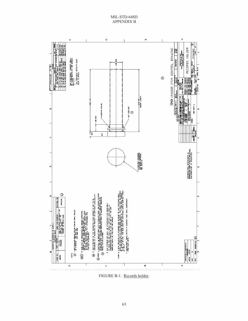
MIL-STD-648D APPENDIX B
63
FIGURE B-1. Records holder.

MIL-STD-648D APPENDIX B
64
FIGURE B-2. Center lift.

MIL-STD-648D APPENDIX B
65
FIGURE B-3. Sling, hoisting MK 105 MOD 0.
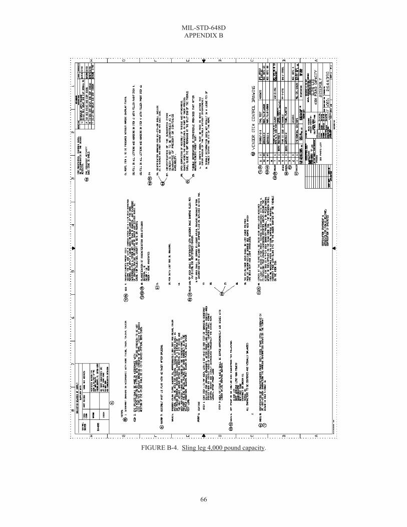
MIL-STD-648D APPENDIX B
66
FIGURE B-4. Sling leg 4,000 pound capacity.

MIL-STD-648D APPENDIX B
67
FIGURE B-5. Holder, records.

MIL-STD-648D APPENDIX B
68
FIGURE B-6. Plug humidity indicator.
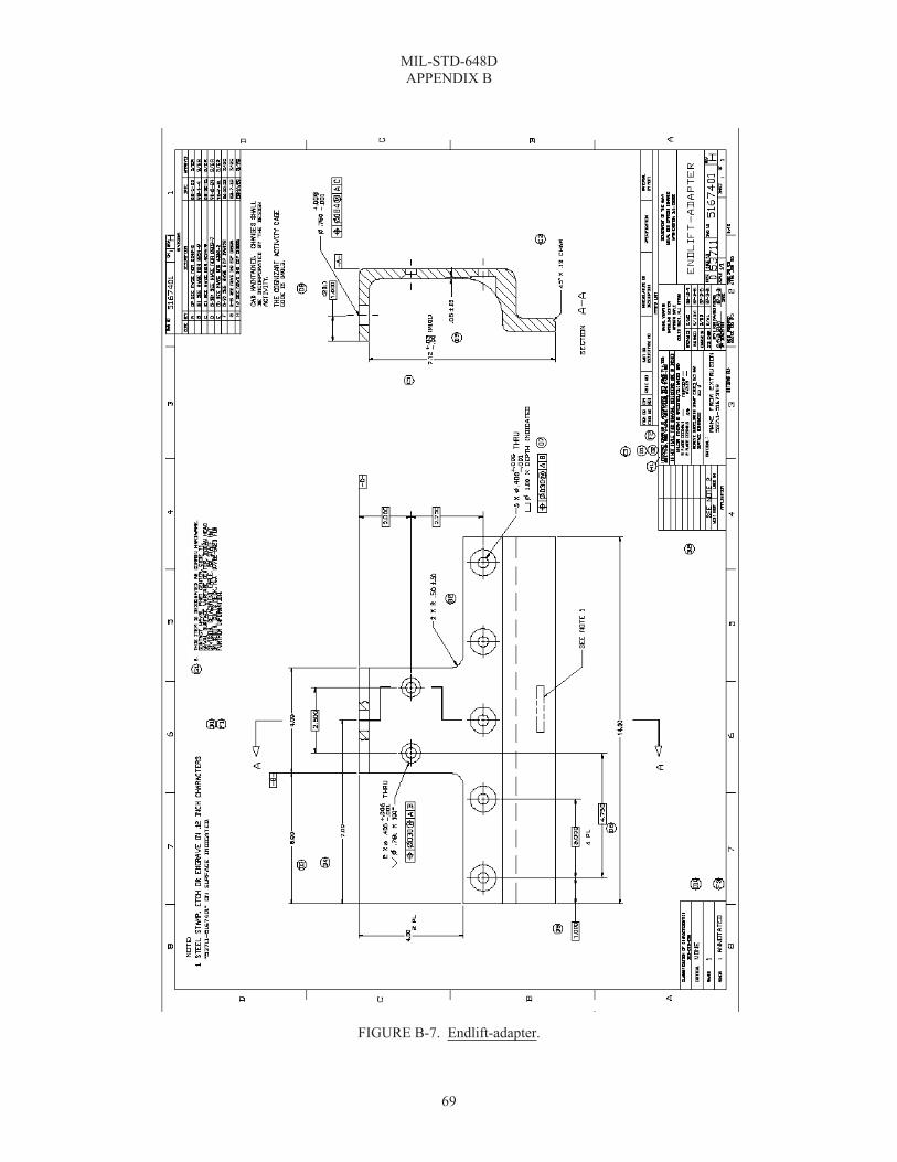
MIL-STD-648D APPENDIX B
69
FIGURE B-7. Endlift-adapter.

MIL-STD-648D APPENDIX B
70
FIGURE B-8. Sling, container lifting MK 109 MOD 1.
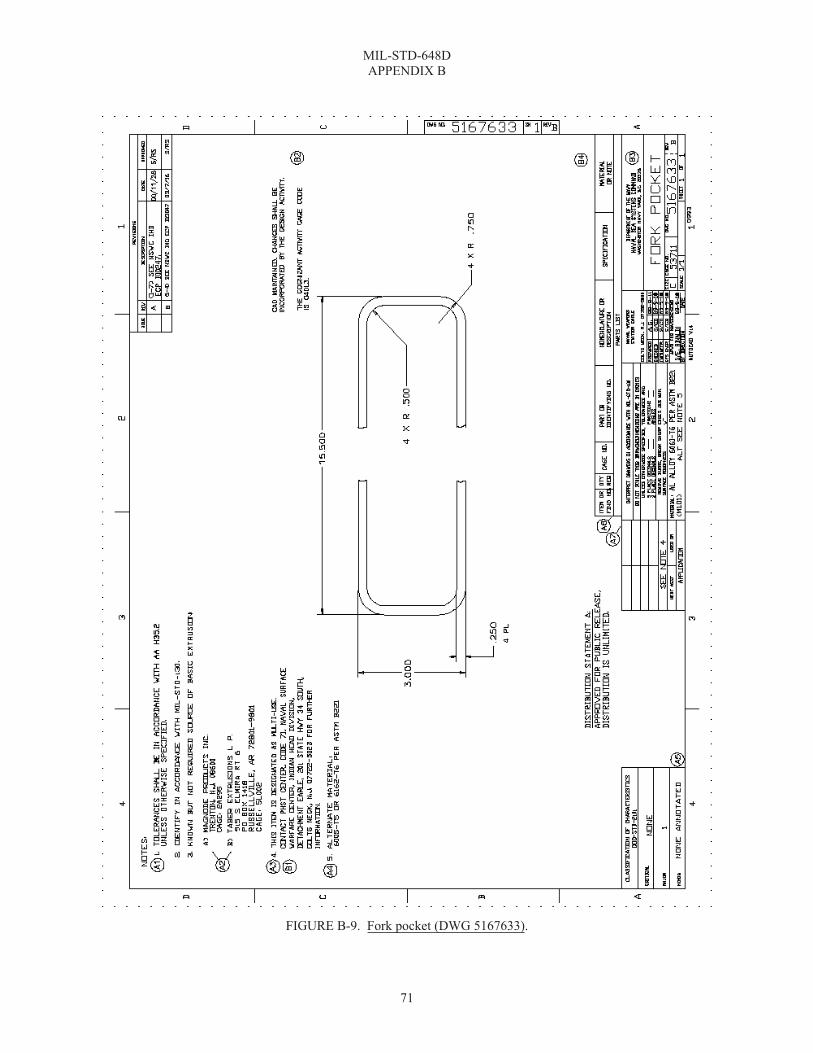
MIL-STD-648D APPENDIX B
71
FIGURE B-9. Fork pocket (DWG 5167633).

MIL-STD-648D APPENDIX B
72
FIGURE B-10. Fork pocket (DWG 5167693).

MIL-STD-648D APPENDIX B
73
FIGURE B-11. Latch.

MIL-STD-648D APPENDIX B
74
FIGURE B-12. Handle.

MIL-STD-648D APPENDIX B
75
FIGURE B-13. Observation window.

MIL-STD-648D APPENDIX B
76
FIGURE B-14. Access port.

MIL-STD-648D APPENDIX B
77
FIGURE B-15. Latch, wide handle.

MIL-STD-648D APPENDIX B
78
FIGURE B-16. Shackle.

MIL-STD-648D APPENDIX B
79
FIGURE B-17. Valve, breather.

MIL-STD-648D APPENDIX B
80
FIGURE B-18. Desiccator.

MIL-STD-648D APPENDIX B
81
FIGURE B-19. Latch.

MIL-STD-648D APPENDIX B
82
FIGURE B-20. Latch, CRES.

MIL-STD-648D APPENDIX B
83
FIGURE B-21. Ring, container lift.

MIL-STD-648D APPENDIX B
84
FIGURE B-22. Container endlift interface (sheet 1 of 3 DWG 6214131).

MIL-STD-648D APPENDIX B
85
FIGURE B-23. Container endlift interface (sheet 2 of 3 DWG 6214131).

MIL-STD-648D APPENDIX B
86
FIGURE B-24. Container endlift interface (sheet 3 of 3 DWG 6214131).

MIL-STD-648D APPENDIX C
87
ELECTROSTATIC PROPERTIES OF MATERIALS
C.1 SCOPE
C.1.1 Scope. This appendix describes the test used to determine the electrostatic properties of materials in film and sheet form, by measuring the time required to induce a charge on the surface of the material, measure the intensity and polarity of the charge, as well as the time required for complete dissipation of the induced charge. This method does not determine the surface, volume, or insulation resistivities of the materials. This appendix is not a mandatory part of the standard. The information contained herein is intended for guidance only.
C.2 DEFINITION
C.2.1 Electrostatic properties. Electrostatic properties are defined as the ability of a material, when grounded, to dissipate a charge induced on the surface of the material.
C.3 APPARATUS
a. A metal template, 5 by 3 by 1⁄8 inches. b. A high voltage source, 0 to 15 KV, positive and negative. c. An electrometer for measuring volts, amperes, and ohms with a full scale reading on 0.01, 0.1, 1.0, 10, and
100, or an oscilloscope with a response of 1 microsecond per division, or equivalent. d. Electrostatic test chamber illustrated on figure C-1. e. A single channel, pen type recorder with speeds of 0.5, 1.0, 2.0, 4.0, and 8.0 inches per minute and per
second. f. A desiccating chamber for conditioning specimens. g. Two knife blade switches, hooked up so that when one is opened the other will close. h. The equipment will be assembled as illustrated on figure C-2. i. A chamber or room uniformly maintained at 73±3.5 °F and 50±5 percent relative humidity in which to
perform tests.
C.4 SPECIMENS
a. Select specimens at random and in sufficient number to represent adequately the variation of the material. A minimum of three specimens per condition per sample are required.
b. Each specimen will be 5 by 3 inches and will be free of defects, such as holes, cracks, and tears. If the specimen is coated, the coating will be continuous.
C.5 CONDITIONING
a. Prior to testing, expose one-third of the specimens for 12 days in an oven uniformly maintained at 160±5 °F; one-third of the specimens in a horizontal position for 24 hours under a continuous water shower; and �of the specimens in an atmosphere uniformly maintained at 73±5 °F and 50±5 percent relative humidity.
b. Unless otherwise specified in the CIDS, all specimens will be placed in the desiccating chamber for a minimum of 24 hours immediately before testing, as specified in section C.6.
C.5.1 Test environment. Perform tests in an atmosphere uniformly maintained at 73±5 °F and dry a condition of less than 15 percent relative humidity. This relative humidity can be obtained by inserting a dish (approximately 4-inch diameter) containing 50 grams of anhydrous calcium chloride into the test chamber. The anhydrous calcium chloride will be replaced daily.
C.6 PROCEDURE
a. Calibration is as follows: (1) Turn on all components and allow to warm up, as noted in the operations manual for the particular
item. (2) Set multiplier switch of the electrometer at 10 and the “operate” switch at “zero check”.

MIL-STD-648D APPENDIX C
88
(3) Close the ground switch and adjust the high voltage for 5 KV output. (4) Mount a 0.1- by 3- by 5-inch aluminum panel between the electrodes in the test chamber so that the
detector head is directly in the center of the panel. Tighten the four wing nuts to secure the panel. (5) Adjust speed of recorder chart at 1 inch/minute, move operate switch to “operate” position and close
the high voltage switch to apply 5 KV to test panel. (6) Move multiplier switch until the meter needle reads maximum without exceeding the limits of the
meter. Check to see if the charge indicated by the meter is identical to that being recorded on the chart. (7) Close ground switch to remove the charge. When meter reaches zero, stop chart and move operate
switch on electrometer to “zero check” position. (8) Repeat this procedure for both positive and negative charges.
b. Each specimen will be mounted, vertically, between the electrodes and the wing nuts tightened to ensure intimate contact between specimen and electrodes.
c. Set chart speed at 0.5 inch/second. Turn on recorder. Turn meter switch to plus or minus, depending on charge to be applied. Move “operate” switch to position and then close charging switch to apply 5 KV to test specimen.
d. When the meter needle stops rising, indicating the specimen has received its maximum charge, close the ground switch to remove the charge.
e. When the needle reaches zero or after 10 seconds, whichever comes first, stop recorder and move operate switch to zero.
f. Charge each specimen three times for both positive and negative charges, allowing specimen to remain grounded for ten minutes after each charging cycle to remove any residual charge on the specimen.
g. Calculate charge decay time by measuring the horizontal distance on the chart from the point where the specimen was grounded to the point where the needle reached zero. With the speed of the chart known, calculate the decay time for each specimen.
C.7 REPORT
Report the facts pertinent to the test.
a. State that the test was conducted in accordance with this procedure or describe any deviations. b. Identify the specimen and specific material tested. c. Results of test.
(1) State the decay time for each specimen for both positive and negative charges, as calculated in C.6.g. (2) State that material was tested as received, aged, and exposed to shower.
C.8 NOTES
a. The purpose of this procedure is to evaluate the electrostatic buildup and dissipation properties of pack-aging materials used to fabricate enclosures primarily for missiles and missile components subjected, in a small degree, to direct climatic exposure. The test is particularly applicable to barrier materials especially formulated to prevent the buildup or retention of electrostatic potential under any atmospheric conditions, the objective being to maximize explosive safety and to preclude ignition of stray flammable materials by electrostatic discharge.
b. The Keithley 621 Electrometer may be used. Other settings may apply if another suitable electrometer of different design is used.
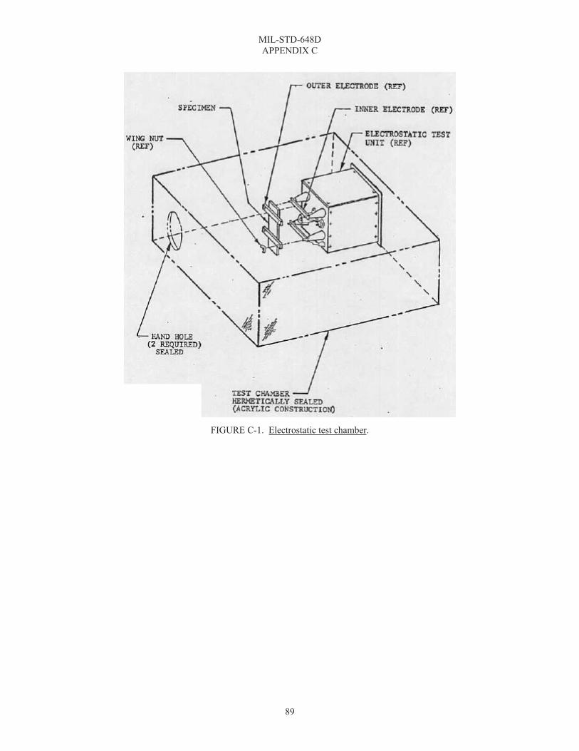
MIL-STD-648D APPENDIX C
89
FIGURE C-1. Electrostatic test chamber.

MIL-STD-648D APPENDIX C
90
FIGURE C-2. Electrostatic test arrangement.

MIL-STD-648D APPENDIX C
91
FIGURE C-3. Electrostatic test.

MIL-STD-648D APPENDIX C
92
FIGURE C-4. Electrostatic detector.

MIL-STD-648D APPENDIX C
93
FIGURE C-5. Electrode.

MIL-STD-648D APPENDIX D
94
SUPERIMPOSED-LOAD TEST (STACKABILITY, WITH DUNNAGE)
D.1 SCOPE
D.1.1 Scope. This appendix provides procedures for determining the ability of shipping containers to resist loads, such as imposed on the bottom container of a stack of similar containers in storage, or on a container supporting top dunnage and superimposed lading; and for determining the ability of the packaging and packing methods to provide protection to the contents when the pack is so loaded. This appendix is not a mandatory part of the standard. The information contained herein is intended for guidance only.
D.2 DEFINITIONS
D.2.1 Packing. The levels of packing to be provided for any item, or contents, are dependent upon the handling, shipping, and storage conditions which the container or pack may be expected to encounter. For the purpose of this standard, the levels of packing will be defined as:
D.2.1.1 Level A. Level A is the degree of preservation or packing required for protection of materiel against the most severe conditions known or anticipated to be encountered during shipment, handling, and storage. Preservation and packaging designated Level A will be designed to protect materiel against direct exposure to extremes of climate, terrain, operational and transportation environments without protection other than that provided by the pack. The conditions to be considered include, but are not limited to:
a. Multiple handling during transportation and in-transit storage from point of origin to ultimate user. b. Shock, vibration, and static loading during shipment. c. Loading on ship deck, transfer-at-sea, helicopter delivery, and offshore or over-the-beach discharge, to
ultimate user. d. Environmental exposure during shipment or during in-transit operations where port and warehouse
facilities are limited or non-existent. e. Extended open storage in all climatic zones. f. Static loads imposed by stacking.
D.2.1.2 Level B. Level B is the degree of preservation or packing required for protection of materiel under known favorable conditions during shipment, handling, and storage. Preservation and packing designated Level B will be designed to protect materiel against physical damage and deterioration during favorable conditions of shipment, handling, and storage. The conditions to be considered include but are not limited to:
a. Multiple handling during transportation and in-transit storage. b. Shock, vibration, and static loading of shipment worldwide by truck, rail, aircraft, or ocean transport. c. Favorable warehouse environment for extended periods. d. Environmental exposure during shipment and in-transit transfers, excluding deck loading and offshore
cargo discharge. e. Stacking and supporting superimposed loads during shipment and extended storage.
D.2.2 Top dunnage. Pieces of relatively stiff material, usually wood, laid across the top of a container or layer of containers to carry the weight of superimposed lading to the sides of the containers.
D.3 APPARATUS
D.3.1 Top superimposed-load test. In conducting the top superimposed-load test, any convenient method may be used for placing the load on top of the container; such as a hoist, a block and tackle, or by hand. The load may also be applied and maintained by means of a testing machine.

MIL-STD-648D APPENDIX D
95
D.4 SPECIMEN
D.4.1 Contents of container. One container and its contents will constitute a single specimen. The container will be loaded for the test with the interior packing and the actual contents for which it was designed. If use of the actual contents is not practical, a dummy load will be substituted to simulate such contents in weight, shape, and position in the container. The contents, or dummy load, will be blocked, braced, and cushioned in place, as for shipment.
D.5 CONDITIONING OF SPECIMEN
D.5.1 Test specimen. Unless otherwise specified in the CIDS, no special conditioning of the test specimen will be necessary.
D.6 PROCEDURE
a. The specimen will be placed on its bottom on a flat, level, rigid floor. A prescribed load will be applied to the top of the container in a manner simulating the effect of similar containers being stacked on top, and the load will be allowed to remain in placed for a prescribed period of time. The bearing of the top superimposed load will be on the same load-bearing areas that the skids, rubbing strips, or other base members would make on the container top. When the test is conducted to determine satisfactory performance of a container and unless otherwise specified in the CIDS, the prescribed period of time will be 1 hour and the prescribed load will be as follows:
16�H W=P× H ×S or 200×A×S;
(1) Whichever is larger. (2) Where:
(a) W = Prescribed top superimposed load, in pounds. (b) P = Weight of the loaded container, in pounds. (c) H = Height of container, in feet. (d) A = Area of top of container, in square feet. (e) S = 2.0 for Level A packing. (f) S = 1.5 for Level B packing.
1. If the principal support structure is a plastic or other non-metallic material with a tendency to creep or deteriorate when exposed to elevated temperatures or very humid conditions, the test will be repeated at a temperature of 120±5 °F and 90 percent relative humidity for a period of 168 hours. In this latter case, the constant “S” will be 1.0.
b. A record will be made of any changes or breaks in the container, such as apparent buckling or failure of members in the sides or ends. Any vertical deflections of the sides and ends will be measured from taut horizontal string lines stretched between nails in the top corners of each side and end. In addition, bulging of the side and end panels will be measured from a vertical straight edge (see figure D-1). Observations will be made to determine if the distortions were sufficient to damage or dislodge the interior packing or contents.
D.7 REPORT
Following the tests, a report will be written which will include the following:
a. A statement that the test was conducted in compliance with this procedure, or a description of the deviation from this procedure. Report all options selected and “otherwise specified” details that were followed, as permitted in D.5.1 and D.6.a.
b. Dimensions of the container, its structural details, kind of materials, spacing, size, and type of fasteners, methods of closing and strapping, and the net and gross weights.
c. A description of the contents of the container including blocking, bracing, and cushioning or isolation system, and a record of the deflections under load.

MIL-STD-648D APPENDIX D
96
d. The results of the test, describing the final condition of both container and contents. e. When the test is conducted to determine satisfactory performance of a container or pack, the report will
include a statement that the container or pack either attained or did not attain the specified performance. If not specified in the CIDS, it is suggested that satisfactory performance will consist of:
“When subjected to the top superimposed-load test, the contents (except a dummy load) will show no functional or physical damage, and the container and packing will show no functional damage. Damage to the exterior shipping container which is the result of improper interior packaging, blocking, or bracing will be cause for rejection. Structural damage to the exterior shipping container which would result in either spilling of the contents or failure of the container in subsequent handling is cause for rejection. There will be no evidence of a substantial amount of shifting of the interior packing or the contents within the exterior shipping container that would create conditions likely to cause damage during shipment, storage, and reshipment of the container.”
f. The report will include a statement of any observations that might help in improving the container or the methods of packing.
D.8 NOTES
a. This test is meant to simulate the top superimposed loads imposed by stacking of like containers, as in storage, or by stowing lading upon top dunnage in the hold of a ship. It is intended that this test will be used only on containers that are likely to be stressed in this manner. Details are given with the qualification, “unless otherwise specified”, in paragraphs regarding:
(1) Conditioning of specimens (see D.5.1). (2) Load and duration of load (see D.6.a).
b. Although the recommended period of time for the top superimposed-load test is only 1 hour, the use of the factor for Levels A and B packing ensures a load-carrying capacity adequate for longtime loading and an occasional application of impact loads.
FIGURE D-1. Top superimposed-load test.

MIL-STD-648D APPENDIX E
97
SUPERIMPOSED-LOAD TEST (UNIFORMLY DISTRIBUTED, WITHOUT DUNNAGE)
E.1 SCOPE
E.1.1 Scope. This appendix provides procedures for determining the ability of shipping containers to resist loads superimposed on their tops, as imposed by piling without top dunnage, many small, heavy packages on a container, and for determining the ability of the packaging and packing methods to provide protection to the contents when the pack is so loaded. This appendix is not a mandatory part of the standard. The information contained herein is intended for guidance only.
E.2 DEFINITIONS
E.2.1 Packing. The levels of packing to be provided for any item or contents are dependent upon the handling, shipping, and storage conditions which the container or pack may be expected to encounter. For the purpose of this standard, the levels of packing will be defined as:
E.2.1.1 Level A. Adequate packing to provide protection against handling, shipping, and storage hazards during worldwide distribution.
E.2.1.2 Level B. Adequate packing to provide protection against handling, shipping, and storage hazards, that may occur during multiple domestic shipments or which are known to be less hazardous than those for Level A.
E.2.2 Top dunnage. Pieces of relatively stiff material, usually wood, lain across the top of a container or layer of containers to carry the weight of superimposed lading to the sides of the containers.
E.3 APPARATUS
E.3.1 Top superimposed-load test. In conducting the top superimposed-load test, any convenient method may be used for placing the load on top of the container; such as a hoist, a block and tackle, or by hand. A sufficient quantity of weights not greater than 10 by 10 inches in outside length and width will be provided. Weights may be boxes loaded with lead or other material.
E.4 SPECIMEN
E.4.1 Contents of container. One container and its contents will constitute a single specimen. The container will be loaded for the test with the interior packing and the actual contents for which it was designed. If use of the actual contents is not practical, a dummy load will be substituted to simulate such contents in weight, shape, and position in the container. The contents, or dummy load, will be blocked, braced, and cushioned in place, as for shipment.
E.5 CONDITIONING OF SPECIMEN
E.5.1 Test specimen. Unless otherwise specified in the CIDS, no special conditioning of the test specimen will be necessary.
E.6 PROCEDURE
a. The specimen will be place on its bottom on a flat, level, rigid floor. Weights will be placed on top of the container in a symmetrical pattern approximating uniform loading, so that they do not extend over the sides or ends of the top surface. There will be one weight to each 1-foot square of top surface and each weight will be whatever is necessary to attain the prescribed load for the top area. The load will be allowed to remain in place for a prescribed period of time. When the test is conducted to determine satisfactory performance of a container and unless otherwise specified in the CIDS, the prescribed period of time of loading will be 1 hour and the prescribed load will be as follows:
(1) W = Top area in square feet by 50 by S, where: (2) W = Prescribed top superimposed load, in pounds. (3) S = 2.0 for Level A packing. (4) S = 1.5 for Level B packing.
MIL-STD-648D APPENDIX E
98
b. Measurements of distortion will be made and recorded immediately before the load is removed, and of any changes or breaks in the container, such as apparent buckling or failure of members in the tops, sides, or ends. Any vertical deflections of the sides and ends will be measured from taut horizontal string lines stretched between nails in the top corners of each side and end. In addition, bulging of the side and end panels will be measured from a vertical straightedge. The cupping of the top will be measured similarly by using a straightedge across the top a midlength of the specimen (see figure E-1). Observations will also be made and recorded to determine if the distortions are sufficient to damage or dislodge any portion of the container, the interior packing or contents. After removal of the load, the extent of recovery from distortions will be observed and recorded.
E.7 REPORT
Following the test, a report will be written which will include the following:
a. A statement that the test was conducted in compliance with this procedure, or a description of the deviation from this procedure. Report all options selected and “otherwise specified” details that were followed, as permitted in E.5.1 and E.6.a.
b. Dimensions of the container, its structural details, kind of materials, spacing, size and type of fasteners, methods of closing and strapping, and the net and gross weights.
c. A description of the contents of the container including blocking, bracing, and cushioning. d. The results of the test, describing the final conditions of both container and contents, and a record of the
deflections under load. e. When the test is conducted to determine satisfactory performance of a container or pack, the report will
include a statement that the container or pack either attained or did not attain the specified performance. If not specified in the CIDS, it is suggested that satisfactory performance will consist of:
“When subjected to the top superimposed-load test, the contents (except a dummy load) will show no functional or physical damage, and the container and packing will show no functional damage. Damage to the exterior shipping container, which is the result of improper interior packaging, blocking, or bracing, will be cause for rejection. Structural damage to the exterior shipping container, which would result in either spilling of the contents or failure of the container in subsequent handling, is cause for rejection. There will be no evidence of a substantial amount of shifting of the contents within the exterior shipping container that would create conditions likely to cause damage during shipment, storage, and reshipment of the container.”
f. The report should include a statement of any observations that might help in improving the container or the methods of packing.
E.8 NOTES
a. This test is meant to simulate the top superimposed loads, as imposed by piling without dunnage many small, heavy packages on a container. It is intended that this test will be used only on containers that are likely to be stressed in this manner. Details are given with the qualification, “unless otherwise specified”, in paragraphs regarding:
(1) Conditioning of specimens (see E.5.1). (2) Load and duration of load (see E.6.a).
b. Although the recommended period of time for the top superimposed-load test is only 1 hour, the use of the factor for Levels A and B packing ensures a load-carrying capacity adequate for longtime loading and an occasional application of impact loads.

MIL-STD-648D APPENDIX E
99
FIGURE E-1. Top superimposed-load test.

MIL-STD-648D APPENDIX F
100
VIBRATION (REPETITIVE SHOCK) TEST
F.1 SCOPE
F.1.1 Scope. This appendix provides procedures intended to indicate whether or not a package is adequate to prevent damage to either the packaging or the contents when the package is tested unattached on the platform of a package vibration testing machine at frequencies below 5 hertz. Either the package bounces on the platform, and receives repetitive shocks and vibration of an indiscrete and variable nature; or the package does not leave the platform. Shocks applied to the package excite each component at its own natural frequency, but when the package does not leave the platform, only those components that vibrate in resonance with the platform vibration are excited. This procedure is useful to predict whether or not such vibrations in transportation are likely to cause damage to the packaging or contents when the shipment is not securely tied down to the floor of the vehicle. Supplementary functional tests of the package contents may be necessary to evaluate functional damage. The procedure is not intended for the development of design parameters for shock and vibration isolation systems. This appendix is not a mandatory part of the standard. The information contained herein is intended for guidance only.
F.2 DEFINITIONS
F.2.1 Shock. A blow, impact, collision, jar, or similar instantaneous application of energy or force. (A shock will cause some vibration in an item or package.)
F.2.2 Vibration. The continuous oscillation of an element or body relative to a suitable reference point.
F.3 APPARATUS
F.3.1 Platform. A platform of suitable size and weight-carrying capacity supported on a mechanism that will maintain the surface, essentially horizontal as it vibrates the platform, so that the vertical component of the motion is approximately sinusoidal. (A rotary motion of the platform is acceptable.) The amplitude of the vibration will be ½ inch (1-inch double amplitude). The frequency will be variable within the approximate range from 3 to 5 hertz and will be controlled to produce the platform vibration specified in F.6.
F.3.2 Restraining devices. Fences, barricades, or blocking that can be attached to the platform to keep the specimen in position on the platform without unnecessarily restricting the vertical or rotational movements of the specimen.
F.4 SPECIMENS
F.4.1 Contents of container. One container and its contents will constitute a single specimen. The container will be loaded for the test with the interior packing and the actual contents for which it was designed. If use of the actual contents is not practical, a dummy load will be substituted to simulate such contents in weight, weight distribution, rigidity, shape, and position in the container. The contents, or dummy load, will be blocked, braced, and cushioned in place, as for shipment.
a. If the intended contents or a fully representative dummy load, such as a reject item, are to be used in the package, their condition, before and after test, must be determined by appropriate methods to establish the extent of damage suffered in the test.
b. If a dummy load is to be used, unless it is fully representative of the intended contents, the ability of the package to prevent damage can be determined only by indirect methods, such as comparison of accelerations measured on the dummy load and fragility factors for the intended contents.
F.5 CONDITIONING
F.5.1 Test specimen. Unless otherwise specified in the CIDS, no special conditioning of the specimen will be necessary. The condition of the specimen and any tests performed prior to the vibration test will be recorded.
MIL-STD-648D APPENDIX F
101
F.6 PROCEDURE
a. The specimen will be placed on but not fastened to the platform. If the specimen might be shipped in other than an upright position, the specimen will be placed in such a position; and if more than one position is reasonable, the test will be interrupted and the position changed so that the specimen is tested for equal periods of time in each reasonable shipping position. Midway in the period of time that the specimen is tested resting on each surface, the specimen will be rotated 180 degrees if the specimen rocks on the platform. Unless failure occurs, the total time of vibration will be 2 hours if the specimen is tested in one position; and if tested in more than one position, the total time will be 3 hours.
b. Restraining devices will be attached to the platform to prevent the specimen from moving off the platform and, if necessary, to prevent excessive rocking of the specimen. The restraining devices should be adjusted to per-mit unrestrained movement of the specimen from its centered position, about ½ inch, in any horizontal direction.
c. With the specimen in one position, vibrate the platform at ½-inch amplitude (1-inch double amplitude) starting at a frequency of about 3 cycles per second. Steadily increase the frequency until the package leaves the platform (i.e., until a 1⁄16 inch thick “feeler” may be momentarily slid freely between every point on the specimen and the platform at some instant during each cycle) or until the frequency reaches that at which the maximum platform acceleration is 1±0.1 times the acceleration of gravity. If circular input motion is used, table frequency will be adjusted to assure that one edge of the container leaves the table not less than 0.1875 inches on each cycle. This test is normally conducted at an ambient temperature. While observing to detect development of any failure, continue to vibrate at such frequency until the total time of vibration in the position is completed. Observe and record whether or not the specimen leaves the platform and the frequency maintained.
d. If the specimen is to be tested in more than one position, repeat F.6.c for each position. e. After the total period of vibration is complete, inspect the packaging and the contents for evidence of
damage. Make appropriate functional or other tests to establish whether or not the item suffered damage.
F.7 REPORT
Immediately following each test, the report (official record) of the facts pertinent to the test will be completed, and will include the following:
a. A statement that the test was conducted in compliance with this procedure, or a description of the deviations from this procedure. Report all options selected and details of otherwise specified procedure that were followed, as permitted in (F.3) Identify apparatus and its limits, (F.5) Conditioning, (F.6) Procedure selections and specifically identify instrumentation.
b. Identification of the specimen, the specific packaging, and contents tested. c. The results of the test, stating the frequency of vibration in each test position and whether or not the
specimen left the platform. Describe any damage to the packaging or contents, or state no damage. Record per-tinent dimensions taken before, during or after the test. Refer to any supplementary tests to evaluate effects of this vibration test.
d. When the test is performed to check compliance with the requirements, state that the specimen did not meet the requirements and give the source for the requirements.
e. When the test is conducted to evaluate or compare products or methods, the report will include a statement of any observations that may lead to improvements. The report will include a statement that the contain-er or pack either attained or did not attain the specified performance. If not specified in the CIDS, it is suggested that the following be cause for rejection:
(1) Functional or physical damage to the contents. (2) Functional damage to the container. (3) Shock forces on the contents (or dummy load) which exceeds the established fragility of the contents. (4) Failure of a vapor or waterproof container to prevent vapor transmission or water leakage
within specified limits.
MIL-STD-648D APPENDIX F
102
(5) Structural damage to the container which may result in damage to the contents during subsequent shipping, handling, or storage. Substantial spillage, exposure, or shifting of the contents is an example of such damage. Minor damage, such as dents, paint chipping, or the crushing of wood members, which do not impair the function of the container, are not causes for rejection.
F.8 NOTES
Not applicable.
MIL-STD-648D APPENDIX G
103
FREE-FALL DROP TEST
G.1 SCOPE
G.1.1 Scope. This appendix provides procedures for determining the ability of containers to withstand impacts and the ability of packaging and packing methods to protect the contents when the pack is subjected to free-fall drops. This procedure is appropriate for use with all containers weighing up to 150 pounds, except those with skids or those having any edge or diameter over 60 inches. This appendix is not a mandatory part of the standard. The information contained herein is intended for guidance only.
G.2 DEFINITIONS
G.2.1 Packing. The levels of packing to be provided for any item, or contents, are dependent upon the handling, shipping, and storage conditions which the container or pack may be expected to encounter. For the purpose of this standard, the levels of packing will be defined as:
G.2.1.1 Level A. Level A is the degree of preservation of packing required for protection of materiel against the most severe conditions known or anticipated to be encountered during shipment, handling, and storage. Preservation and packaging designated Level A will be designed to protect materiel against direct exposure to extremes of climate, terrain, operational and transportation environments without protection other than that provided by the pack. The conditions to be considered include, but are not limited to:
a. Multiple handling during transportation and in-transit storage from point of origin to ultimate user. b. Shock, vibration, and static loading during shipment. c. Loading on ship-deck, transfer-at-sea, helicopter delivery, and offshore or over-the-beach discharge, to
ultimate user. d. Environmental exposure during shipment or during in-transit operations where port and warehouse
facilities are limited or non-existent. e. Extended open storage in all climatic zones. f. Static loads imposed by stacking.
G.2.1.2 Level B. Level B is the degree of preservation or packing required for protection of materiel under known favorable conditions during shipment, handling, and storage. Preservation and packing designated Level B will be designed to protect materiel against physical damage and deterioration during favorable conditions of shipment, handling, and storage. The conditions to be considered include but are not limited to:
a. Multiple handling during transportation and in-transit storage. b. Shock, vibration, and static loading of shipment worldwide by truck, rail, aircraft, or ocean transport. c. Favorable warehouse environment for extended periods. d. Environmental exposure during shipment and in-transit transfers, excluding deck loading and offshore
cargo discharge. e. Stacking and supporting superimposed loads during shipment and extended storage.
G.3 APPARATUS
Any suitable apparatus may be used that conforms to the following requirements:
a. Permits the container to be placed in a position prior to release that will assure free unobstructed fall to impact the container at the orientation and in the direction required.
b. Permits accurate and convenient control of the height of drop. c. Utilizes lifting devices that will not damage the containers. d. Provides an instantaneous release mechanism that does not impart rotational or sidewise forces to the test
container. e. Provides a rigid and level steel surface not less than ½ inch thick, integral with a solid mass of concrete,
steel, or stone sufficient to absorb all shock without displacement.

MIL-STD-648D APPENDIX G
104
f. Provides, when required by the CIDS, an additional and properly positioned hazard to test a container’s ability to protect a specific point of critical vulnerability of its contents. This hazard will consist of a straight block of oak or other relatively heavy hard wood 4 by 4 at least 24 inches long with the edges rounded to a radius of ¼±1⁄16 inch. The detail specifications will include any further description of the impacting object, the attitude, the point of impact, height, and number of drops.
G.4 SPECIMEN
G.4.1 Contents of container. One container and its contents will constitute a single specimen. The container will be loaded for the test with the interior packing and the actual contents for which it was designed. If use of the actual contents is not practical, a dummy load will be substituted to simulate such contents with weight, rigidity, shape, and CG position in the container. The contents, or dummy load, will be blocked, braced, and cushioned in place, as for shipment, and appropriately instrumented to record shock forces or deflections during the test.
G.5 CONDITIONING
G.5.1 Test specimen. All tests will be conducted at room temperature (ambient) except as noted below.
G.6 PROCEDURE
G.6.1 Bags. Unless otherwise specified in the CIDS, each bag specimen will be dropped once on the filling end and once flatwise, (seams horizontal) from a height of 48 inches.
G.6.2 Cylindrical containers. Unless otherwise specified in the CIDS, cylindrical containers, barrels, pails, etc., will be subjected to one of the procedures described below. The container is to be dropped, once flatwise, on each end. The top and bottom rim or chime drops are to be made wherein the container CG is directly above the striking point at the instant of release. A plumb line aligned with the center point of the drop table (see figure G-1) may be used to position the container. The rim drop will be made in pairs, one on the top rim and one on the bottom rim. For the two drops of each pair, the container will strike on diagonally opposite quadrants of the top and bottom rims. If a total of more than four rim drops is specified, the additional drops will be on sections not previously dropped upon.
Procedure A. One drop on each end (2 drops).
Procedure B. One drop on each half of the top and bottom rims (4 drops).
Procedure C. One drop on each quadrant of the top and bottom rims (8 drops).
Procedure D. One drop on each half of the top and bottom rims, one drop on each end, and two drops on the cylindrical side of the container at 90 degrees to each other (8 drops).
G.6.3 Rectangular containers. Unless otherwise specified in the CIDS, rectangular containers will be subjected to one or more of the following procedures, as described below, but dropped not more than once on any flat face, edge, or corner. For edgewise drops, the striking edge of the package will be parallel with the dropping surface at the instant of release. For edgewise and cornerwise drops, the package CG will be directly above the striking edge or corner of the package at the instant of release (see figure G-1).
Procedure A. One drop on each flat face, edge and corner (26 drops).
Procedure B. One drop on each flat face (6 drops).
Procedure C. One cornerwise drop followed by one edgewise drop on each of the three edges radiating from the struck corner (4 drops).
Procedure D. One cornerwise drop on each of the four bottom corners (4 drops).
Procedure E. One cornerwise drop on each of the eight corners (8 drops).

MIL-STD-648D APPENDIX G
105
Procedure F. One drop on each edge (12 drops).
Procedure G. One cornerwise drop on each of two sets of diagonally opposite corners; followed by one flat drop on the bottom, top, and two adjacent sides (8 drops).
If the test specimen contains materials which are significantly affected by temperature, the test will be conducted at the specified temperature extremes. Unless otherwise specified in the CIDS, half of the drops indicated by the above procedures will be made at a stabilized temperature of -20±5 °F and half will be made at a temperature of 140±5 °F.
G.6.4 Drop height. All package drops will be made so that the package falls freely through the specified vertical free-fall distance. (See table G-I.)
G.7 REPORT
Following the tests, a report will be written which will include the following:
a. A statement that the test was conducted in compliance with this procedure or a description of the deviation from this procedure. Report all options selected and “otherwise specified” details that were followed, as permitted in G.2.1, G.5.1, and G.6.1.
b. Container dimensions, container structural details, type of materials used, spacing, size and type of fasteners, methods of closing and strapping, and the net and gross weights.
c. A description of the contents of the container, including blocking, bracing, and cushioning. d. The results of the test, describing the final conditions of both container and contents. e. When the test is conducted to determine satisfactory performance of a container or pack, the report will
include a statement that the container or pack either attained or did not attain the specified performance. If not specified in the CIDS, it is suggested that the following be cause for rejection:
(1) Functional or physical damage to the contents. (2) Functional damage to the container. (3) Shock forces on the contents (or dummy load) which exceeds the established fragility of the contents. (4) Failure of a vapor or waterproof container to prevent vapor transmission or water leakage within
specified limits. (5) Structural damage to the container which may result in damage to the contents during subsequent
shipping, handling, or storage. Substantial spillage, exposure, or shifting of the contents is an example of such damage. Minor damage, such as dents, paint chipping, or the crushing of wood members, which do not impair the function of the container, are not causes for rejection.
f. The report should include information acquired through observation to improve the container or methods of packing.
G.8 NOTES
This method specifically describes only the free-fall drop test procedure. If other tests on the container, such as a preceding exposure test or a subsequent leakage test are desired, then such tests and their sequence should be specified. In this free drop test procedure, details are given with the qualification, “unless otherwise specified”, in paragraphs regarding:
a. Conditioning of specimens (see G.5.1). b. Height of drop, number of drops, points of impact (see G.6.1, G.6.2, and G.6.3). c. This test is meant to simulate the impacts of accidentally dropping a container on its edges, corners, or flat
surfaces.

MIL-STD-648D APPENDIX G
106
TABLE G-I. Height of free-fall drops for containers of various sizes and weights.1/, 2/
Gross weight (within range limits)
Dimension of any edge, height, or diameter
(within range limits)
Height of free-fall drop on corners or edges or flat faces
Pounds Inches Level A inches Level B inches
0 - 15 0 - 30 36 27 15 - 30 30 - 33 30 22 30 - 50 33 - 37 25 19 50 - 75 37 - 42 21 17
75 - 110 42 - 50 19 15 110 - 150 50 - 60 18 14
NOTES: 1/ Use the lowest drop height indicated by either gross weight or dimension. (For example, a container having a
gross weight of 36 pounds and a maximum edge dimension of 425⁄8 inches will be dropped 19 inches for Level A or 15 inches for Level B.)
2/ Containers with gross weight or any one dimension exceeding 150 pounds or 60 inches, respectively, should not be tested by the free-fall method unless warranted by exceptional package design or intended use. (See edgewise- and cornerwise-drop tests and tipover test.)

MIL-STD-648D APPENDIX G
107
FIGURE G-1. Free-fall drop test.

MIL-STD-648D APPENDIX H
108
CORNERWISE-DROP (ROTATIONAL) TEST
H.1 SCOPE
H.1.1 Scope. This appendix provides procedures for determining the ability of large shipping containers to resist the impacts of being dropped on their corners and for determining the ability of the packaging and packing methods to provide protection to the contents when the pack is dropped on its corners. This appendix is not a mandatory part of the standard. The information contained herein is intended for guidance only.
H.2 DEFINITIONS
H.2.1 Large shipping containers. For the purpose of this test, a large shipping container may be a box, case, crate, other container constructed of wood, metal, or other material, or any combination of these for which the free-fall drop test is not considered practical or adequate. Large containers will be considered those having:
a. Gross weight over 150 pounds, b. Length of any edge over 60 inches, or c. Gross weight under 150 pounds and the container is equipped with skids. H.2.2 Packing. The level of packing to be provided for any item or contents is dependent upon the handling
and shipping conditions which the container or pack may be expected to encounter. For the purpose of this standard, the levels of packing will be defined as:
H.2.2.1 Level A. Level A is the degree of preservation or packing required for protection of materiel against the most severe conditions known or anticipated to be encountered during shipment, handling, and storage. Preservation and packaging designated Level A will be designed to protect materiel against direct exposure to extremes of climate, terrain, operational and transportation environments without protection other than that provided by the pack. The conditions to be considered include, but are not limited to:
a. Multiple handling during transportation and in-transit storage from point of origin to ultimate user. b. Shock, vibration, and static loading during shipment. c. Loading on ship deck, transfer-at-sea, helicopter delivery, and offshore or over-the-beach discharge, to
ultimate user. d. Environmental exposure during shipment or during in-transit operations where port and
warehouse facilities are limited or non-existent. e. Extended open storage in all climatic zones. f. Static loads imposed by stacking.
H.2.2.2 Level B. Level B is the degree of preservation or packing required for protection of materiel under known favorable conditions during shipment, handling, and storage. Preservation and packing designated Level B will be designed to protect materiel against physical damage and deterioration during favorable conditions of shipment, handling, and storage. The conditions to be considered include but are not limited to:
a. Multiple handling during transportation and in-transit storage. b. Shock, vibration, and static loading of shipment worldwide by truck, rail, aircraft, or ocean transport. c. Favorable warehouse environment for extended periods. d. Environmental exposure during shipment and in-transit transfers, excluding deck loading and
offshore cargo discharge. e. Stacking and supporting superimposed loads during shipment and extended storage.
H.3 APPARATUS
H.3.1 Cornerwise-drop test. In conducting the cornerwise-drop test, the container may be handled with any convenient equipment, such as a forklift truck, a hoist, or a block and tackle. A smooth, level, concrete surface (or similarly unyielding surface) will be used in performing the cornerwise-drop test.

MIL-STD-648D APPENDIX H
109
H.4 SPECIMEN
H.4.1 Contents of container. One container and its contents will constitute a single specimen. The container will be loaded for the test with the interior packing and the actual contents for which it was designed. If use of the actual contents is not practical, a dummy load will be substituted to simulate such contents in weight, rigidity, shape, and CG, position in the container, and appropriately instrumented to record shock forces or deflections during the test. The contents, or dummy load, will be blocked, braced, and cushioned in place, as for shipment.
H.5 CONDITIONING OF SPECIMEN
H.5.1 Test specimen. All tests will be conducted at room temperature (ambient) except as noted below.
H.6 PROCEDURE
H.6.1 Number and height of drops. The specimen will be placed on its bottom. One corner of the base of the container will be supported on a block nominally 6 inches in height, and a block nominally 12 inches in height will be placed under the other corner of the same end. If the dimensions of the container are such that the 12-inch height cannot be attained without instability, a block of the greatest attainable height will be substituted. These heights will be increased, if necessary, to ensure that there will be no support for the base between the ends of the container when dropping takes place, but should not be high enough to cause the container to slide on the supports when the drop end is raised for the drop. The unsupported end of the container will be raised so that the lower corner of that end reaches the prescribed height and then allowed to fall freely to the concrete surface or similarly unyielding surface (see figure H-1). Unless otherwise specified in 5.2.4, the height of drop for Levels A and B protection will conform to table H-I; the maximum heights will not exceed 36 inches and 27 inches, respectively. Unless otherwise specified in 5.2.4, there will be one drop on each corner of the container base (4 drops). If the test specimen contains materials which are significantly affected by temperature, the test will be conducted while the container is stabilized at the extremes of temperature. In this case, one drop will be made on each of two diagonally opposite corners at -20±5 °F. The test specimen will be allowed to come normally to room temperature prior to conditioning at the other extreme. One drop will then be made on each of the other two diagonally opposite corners at 140±5 °F. Thus, a total of four drops constitutes a complete test.
H.7 REPORT
Following the tests, a report will be written which will include the following:
a. A statement that the test was conducted in compliance with this procedure, or a description of the deviation from this procedure. Report all options selected and “otherwise specified” details that were followed, as permitted in H.2.1, H.5.1, and H.6.1.
b. Container dimensions, container structural details, type of materials used, spacing, size and type of fasteners, methods of closing and strapping, and the net and gross weights.
c. A description of the contents of the container including blocking, bracing, cushioning, or isolation system. d. The results of the test, describing the final condition of both container and contents. e. When the test is conducted to determine satisfactory performance of a container or pack, the report will
include a statement that the container or pack either attained or did not attain the specified performance. If not specified in the CIDS, it is suggested that the following be cause for rejection:
(1) Functional or physical damage to the contents. (2) Functional damage to the container. (3) Shock forces on the contents (or dummy load) which exceeds the established fragility of the contents. (4) Failure of a vapor or waterproof container to prevent vapor transmission or water leakage within
specified limits. (5) Structural damage to the container which may result in damage to the contents during subsequent
shipping, handling, or storage. Substantial spillage, exposure, or shifting of the contents is an example of such damage. Minor damage, such as dents, paint chipping, or the crushing of wood members, which do not impair the function of the container, are not causes for rejection.

MIL-STD-648D APPENDIX H
110
f. The report should include information, acquired through observation, to improve the container or methods of packing.
H.8 NOTES
a. This test is meant to simulate the impacts of accidentally dropping a container on its corners. It is intended that the cornerwise-drop test will be used only on containers that are susceptible to accidental cornerwise drops. The cornerwise-drop test was designed specifically for large or heavy shipping containers that are likely to be handled mechanically rather than manually. Details are given with the qualification, “unless otherwise specified”, in paragraphs regarding:
(1) Definition of large container (see H.2.1). (2) Conditioning of specimen (see H.5.1). (3) Number and height of drops (see H.6.1).
b. When the cornerwise-drop test is performed to evaluate the protection provided for the contents, the rigidity of a dummy load should closely approximate that of the actual contents for which the container was designed.
TABLE H-I. Height of rotational drops for containers of various sizes and weights. 1/
Gross weight (within range limits)
Dimensions of any edge, height, or width (within range limits)
Height of drop on corners
Pounds Inches Level A inches Level B inches
150 - 250 60 - 66 36 27 250 - 400 66 - 72 32 24 400 - 600 72 - 80 28 21
600 – 1,000 80 - 95 24 18 1,000 – 1,500 95 - 114 20 16 1,500 – 2,000 114 - 144 17 14 2,000 – 3,000 Above 144 - No limit 15 12 Above – 3,000 12 9
NOTE: 1/ Use the lowest drop height indicated by either gross weight or dimension. (For example, a container having a gross weight of 440 pounds and a maximum edge dimension of 955⁄8 inches will be dropped
20 inches for Level A tests or 16 inches for Level B tests.)

MIL-STD-648D APPENDIX H
111
FIGURE H-1. Cornerwise drop (rotational).
MIL-STD-648D APPENDIX I
112
EDGEWISE-DROP (ROTATIONAL) TEST
I.1 SCOPE
I.1.1 Scope. This appendix provides procedures for determining the ability of large shipping containers to resist the impacts of being dropped on their edges and for determining the ability of the packaging and pack-ing methods to provide protection to the contents when the pack is dropped on its edges. This appendix is not a mandatory part of the standard. The information contained herein is intended for guidance only.
I.2 DEFINITIONS
I.2.1 Large shipping containers. For the purpose of this test, a large shipping container may be a box, case, crate, or other container constructed of wood, metal, or other material, or any combination of these for which the free-fall drop test is not considered practical or adequate. Large containers will be considered those having:
a. Gross weight over 150 pounds, b. Length of any edge over 60 inches, or c. Gross weight under 150 pounds and the container is equipped with skids.
I.2.2 Packing. The level of packing to be provided for any item or contents is dependent upon the handling and shipping conditions which the container or pack may be expected to encounter. For the purpose of this standard, the levels of packing will be defined as:
I.2.2.1 Level A. Level A is the degree of preservation or packing required for protection of materiel against the most severe conditions known or anticipated to be encountered during shipment, handling, and storage. Preservation and packaging designated Level A will be designed to protect materiel against direct exposure to ex-tremes of climate, terrain, operational and transportation environments without protection other than that provided by the pack. The conditions to be considered include, but are not limited to:
a. Multiple handling during transportation and in-transit storage from point of origin to ultimate user. b. Shock, vibration, and static loading during shipment. c. Loading on ship deck, transfer-at-sea, helicopter delivery, and offshore or over-the-beach discharge, to
ultimate user. d. Environmental exposure during shipment or during in-transit operations where port and
warehouse facilities are limited or non-existent. e. Extended open storage in all climatic zones. f. Static loads imposed by stacking.
I.2.2.2 Level B. Level B is the degree of preservation of packing required for protection of materiel under known favorable conditions during shipment, handling, and storage. Preservation and packing designated Level B will be designed to protect materiel against physical damage and deterioration during favorable conditions of shipment, handling, and storage. The conditions to be considered include but are not limited to:
a. Multiple handling during transportation and in-transit storage. b. Shock, vibration, and static loading of shipment worldwide by truck, rail, aircraft, or ocean transport. c. Favorable warehouse environment for extended periods. d. Environmental exposure during shipment and in-transit transfers, excluding deck loading and
offshore cargo discharge. e. Stacking and supporting superimposed loads during shipment and extended storage.
I.3 APPARATUS
I.3.1 Edgewise-drop test. In conducting the edgewise-drop test, the container may be handled with any con-venient equipment, such as a forklift truck, a hoist, or a block and tackle. A smooth, level, concrete surface (or similarly unyielding surface) will be used in performing the edgewise-drop test.

MIL-STD-648D APPENDIX I
113
I.4 SPECIMEN
I.4.1 Contents of container. One container and its contents will constitute a single specimen. The container will be loaded for the test with the interior packing and the actual contents for which it was designed. If use of the actual contents is not practical, a dummy load will be substituted to simulate such contents in weight, rigidity, shape, and CG position in the container and appropriately instrumented to record shock forces or deflections during the test. The contents or dummy load, will be blocked, braced, and cushioned in place, as for shipment.
I.5 CONDITIONING OF SPECIMEN
I.5.1 Test specimen. All tests will be conducted at room temperature (ambient).
I.6 PROCEDURE
I.6.1 Number and height of drops. The specimen will be placed on its bottom with one end of the base of the container supported on a sill nominally 6 inches high. The height of the sill will be increased, if necessary, to ensure that there will be no support for the base between the ends of the container when dropping takes place, but should not be high enough to cause the container to slide on the supports when the drop end is raised for the drop. The unsupported end of the container will then be raised and allowed to fall freely to the concrete surface or similarly unyielding surface from a prescribed height (see figure I-1). Unless otherwise specified in 5.2.5, the height of drop for Levels A and B protection will conform to table I-I. The maximum heights will not exceed 36 inches for Level A and 27 inches for Level B protection. Unless otherwise specified in 5.2.5, a total of four drops constitute a complete test. If the size of the container and the location of the CG are such that the drop cannot be made from the prescribed height, the height of the sill will be increased. Rectangular containers will be dropped once on each edge of the container base. Cylindrical containers will be dropped on the top and bottom rims at diagonally opposite quadrants. The quadrant pairs will be separated by approximately 90 degrees. If a total of more than four rim drops is specified, the additional drops will be on sections not previously dropped upon. If the test specimen contains materials which are affected by temperature, the test will be conducted while the container is stabilized at the extremes of temperature. Unless otherwise specified in 5.2.5, half the total number of drops will be made at �20±5 °F and half will be made at 140±5 °F.
I.7 REPORT
Following the tests, a report will be written which will include the following:
a. A statement that the test was conducted in compliance with this procedure, or a description of the deviation from this procedure. Report all options selected and “otherwise specified” details that were followed, as permitted in I.2.1, I.5.1, and I.6.1.
b. Container dimensions, container structural details, type of materials used, spacing, size and type of fasteners, methods of closing and strapping, and the net and gross weights.
c. A description of the contents of the container including blocking, bracing, cushioning, or isolation system. d. The results of the test, describing the final condition of both container and contents. e. When the test is conducted to determine satisfactory performance of a container or pack, the report will
include a statement that the container or pack either attained or did not attain the specified performance. If not specified in the CIDS, it is suggested that the following be cause for rejection:
(1) Functional or physical damage to the contents. (2) Functional damage to the container. (3) Shock forces on the contents (or dummy load) which exceeds the established fragility of the contents. (4) Failure of a vapor or waterproof container to prevent vapor transmission or water leakage within
specified limits. (5) Structural damage to the container which may result in damage to the contents during subsequent
shipping, handling, or storage. Substantial spillage, exposure, or shifting of the contents is an example of such damage. Minor damage, such as dents, paint chipping, or the crushing of wood members, which do not impair the function of the container, are not causes for rejection.

MIL-STD-648D APPENDIX I
114
f. The report should include information, acquired through observation, to improve the container or methods of packing.
I.8 NOTES
a. This test is meant to simulate the impacts of accidentally dropping a container on its edges. It is intended that the edgewise-drop test will be used only on containers that are susceptible to accidental edgewise drops. The edgewise-drop test was designed specifically for large or heavy shipping containers that are likely to be handled mechanically rather than manually. Details are given with the qualification, “unless otherwise specified”, in paragraphs regarding:
(1) Definition of large container (see I.2.1). (2) Conditioning of specimens (see I.5.1). (3) Number and height of drops (see I.6.1).
b. When the edgewise-drop test is performed to evaluate the protection provided for the contents, the rigid-ity of a dummy load should closely approximate that of the actual contents for which the container was designed.
TABLE I-I. Height of rotational drops for containers of various sizes and weights. 1/
Gross weight (within range limits)
Dimensions of any edge, height or width (within range limits)
Height of drops on edges
Pounds Inches Level A inches Level B inches
150 - 250 60 - 66 36 27 250 - 400 66 - 72 32 24 400 - 600 72 - 80 28 21
600 – 1,000 80 - 95 24 18 1,000 – 1,500 95 - 114 20 16 1,500 – 2,000 114 - 144 17 14 2,000 – 3,000 Above 145 - No limit 15 12 Above – 3,000 12 9
NOTE: 1/ Use the lowest drop height indicated by either gross weight or dimension. (For example, a container
having a gross weight of 440 pounds and a maximum edge dimension of 955⁄8 inches will be dropped 20 inches for Level A tests or 16 inches for Level B tests.)

MIL-STD-648D APPENDIX I
115
FIGURE I-1. Edgewise drop (rotational).

MIL-STD-648D APPENDIX J
116
TIPOVER TEST
J.1 SCOPE
J.1.1 Scope. This appendix provides procedures for determining the ability of large shipping containers to resist the impacts of being tipped over, and for determining the ability of the packaging and packing methods to provide protection to the contents, when the pack is tipped over. Unless otherwise specified in the CIDS, containers having widths greater than one-fourth the height will not be tested in this manner. This appendix is not a mandatory part of the standard. The information contained herein is intended for guidance only.
J.2 DEFINITION
J.2.1 Large shipping containers. For the purpose of this test, a large shipping container may be a box, case, crate, or other container constructed of wood, metal, or other material, or any combination of these for which or-dinary box tests are not considered practical or adequate. Unless otherwise specified in the CIDS, large containers will be considered as those which measure more than 60 inches on any edge or diameter, or those when loaded have gross weights in excess of 150 pounds.
J.3 APPARATUS
J.3.1 Tipover test. In making the tipover test, the container may be handled with any convenient equipment, such as a forklift truck, a hoist, a block and tackle, or by hand. A smooth, level, concrete slab, pavement, or similarly unyielding surface will be available upon which to perform the tipover test.
J.4 SPECIMEN
J.4.1 Contents of container. One container and its contents will constitute a single specimen. The container will be loaded for the test with the interior packing and the actual contents for which it was designed. If use of the actual contents is not practical, a dummy load will be substituted to simulate such contents in weight, shape, and position in the container. The contents, or dummy load, will be blocked, braced, and cushioned in place, as for shipment.
J.5 CONDITIONING OF SPECIMEN
J.5.1 Test specimen. Unless otherwise specified in the CIDS, no special conditioning of the test specimen will be necessary.
J.6 PROCEDURE
J.6.1 Number and direction of tipover. The specimen will be placed on its bottom and slowly tipped until it falls freely (by its own weight) on its side to a smooth, level, concrete slab or similarly unyielding surface. Unless otherwise specified in the CIDS, two of these tipovers will be made, one on each side or 180 degrees apart on a cylinder. A record will be made of any changes or breaks in the container, such as apparent racking, nail pull, or broken parts and their locations. The packing (blocks, braces, cushions, or other devices) and the contents will be examined carefully and a record made of their condition.
J.7 REPORT
Following the test, a report will be written which will include the following:
a. A statement that the test was conducted in compliance with this procedure, or a description of the deviation from this procedure. Report all options selected and “otherwise specified” details that were followed, as permitted in J.1.1, J.2.1, J.5.1, and J.6.1.
b. Dimensions of the container, its structural detail, kind of material, spacing, size and type of fasteners, methods of closing and strapping, and the net and gross weights.
c. A description of the contents of the container including blocking, bracing, and cushioning. d. The results of the test, describing the final condition of both container and contents.

MIL-STD-648D APPENDIX J
117
e. When the test is conducted to determine satisfactory performance of a container or pack, the report will include a statement that the container or pack either attained or did not attain the specified performance. If not specified in the CIDS, it is suggested that satisfactory performance will consist of:
“When subjected to the tipover test, the contents (except a dummy load) will show no functional or physical damage, and the container and packing will show no functional damage. Damage to the exterior shipping container which is the result of improper interior packaging, blocking, or bracing, will be cause for rejection. Structural damage to the exterior shipping container, which would result in either spilling of the contents or failure of the con-tainer in subsequent handling, is cause for rejection. There will be no evidence of a substantial amount of shifting of the contents within the exterior shipping container that would create conditions likely to cause damage during shipment, storage, and reshipment of the container. Minor container damage, such as chipping of wood members, dents, paint chipping, is not cause for rejection.”
f. The report should include a statement of any observations that might help in improving the container or the methods of packing.
J.8 NOTES
a. This test is meant to simulate the impacts of accidentally tipping over a container. It is intended that the tipover test will be used only on containers that are susceptible to accidental tipovers. Details are given with the qualification, “unless otherwise specified”, in paragraphs regarding:
(1) Scope – excluded containers (see J.1.1). (2) Definition of large containers (see J.2.1). (3) Conditioning of specimens (see J.5.1). (4) Number and direction of tipover (see J.6.1).
b. When the tipover test is performed to evaluate the protection provided for the contents, the rigidity of a dummy load should closely approximate that of the actual contents for which the pack was designed.

MIL-STD-648D APPENDIX K
118
ROLLOVER TEST
K.1 SCOPE
K.1.1 Scope. This appendix provides procedures for indicating the ability of a package to withstand rolling completely over from base to one side, to top, to other side, and onto the base again. This procedure is applicable to packages too large for testing in the revolving drum apparatus, but light enough, or of proportions, so that the package might possibly be rolled over during rough handling. This appendix is not a mandatory part of the standard. The information contained herein is intended for guidance only.
K.2 DEFINITIONS
Not applicable.
K.3 APPARATUS
a. A sufficient area of level, rigid pavement or similarly unyielding surface. b. A forklift truck, or sufficient manpower, to topple the package for each impact.
K.4 SPECIMEN
K.4.1 Contents of container. One container and its contents will constitute a single specimen. The container will be loaded for the test with the interior packing and the actual contents for which it was designed. If use of the actual contents is not practical, a dummy load will be substituted to simulate such contents in weight, shape, and position in the container. The contents, or dummy load, will be blocked, braced, and cushioned in place, as for shipment.
K.5 CONDITIONING
K.5.1 Test specimen. Unless otherwise specified in the CIDS, no conditioning of the specimen is required.
K.6 PROCEDURE
a. The specimen will be placed in its normal upright position on the pavement. The specimen will then be slowly tipped toward one side until it topples and falls by its own weight onto the side. Then topple the specimen so that it falls onto its top. Again, topple the specimen so it falls onto its other side and, finally, topple so it falls onto its base. Observe the container and record any evidence of inadequacies or damage that would impair serviceability of the container.
b. Open the container and examine the blocking, bracing, cushioning, and preservation. Record any evidence of inadequacies or damage that would impair serviceability of the package.
c. If the specimen included the item for which the package was designed, determine and record whether or not the item sustained damage, describe any damage, and record any apparent reasons why damage occurred.
K.7 REPORT
Immediately following each test, the report (official record) of the facts pertinent to the test will be completed, and will include the following:
a. A statement that the test was conducted in compliance with this procedure, or a description of the deviations from this procedure. Report all options selected and details of otherwise specified procedures that were followed as permitted in K.4.1, K.5.1, and K.6.c (give method of determining damage to item).
b. Identification of the item and the specific package tested. c. The results of the test, reporting the evidence of inadequacies and describing damage, or state, “no evidence
of inadequacies and no damage”. d. When the test is performed to check compliance with requirements, state that the specimen did or did not
meet the requirements and give the source for the requirements. e. When the test is conducted to evaluate or compare products or methods, the report will include a statement
of any observations that may lead to improvements.

MIL-STD-648D APPENDIX K
119
K.8 NOTES
a. Details are given with the qualification, “unless otherwise specified”, in the paragraph regarding conditioning (see K.5.1).
b. This procedure should not be used for items too heavy to anticipate rollover in handling. For relatively high, narrow packages, the tipover test may be more appropriate than this rollover test.
MIL-STD-648D APPENDIX L
120
INCLINE-IMPACT TEST
L.1 SCOPE
L.1.1 Scope. This appendix provides procedures for determining the ability of large shipping containers to resist impacts on their surfaces or edges, and for determining the ability of the packaging and packing methods to provide protection to the contents when the pack is impacted on its surfaces or edges. This test may be applied also to unitized loads. This appendix is not a mandatory part of the standard. The information contained herein is intended for guidance only.
L.2 DEFINITION
L.2.1 Incline impact tester. For the purpose of this test, an incline-impact tester will consist of a two-rail steel track inclined 10 degrees from the horizontal, a rolling carriage or dolly, and a rigid bumper (see L.3).
L.3 APPARATUS
L.3.1 Inclined track. The inclined track will accommodate the carriage which will be equipped with steel wheels, not less than 3 inches in diameter, and a renewable face made of dense hardwood or plywood. The bumper at the bottom of the incline will be constructed integrally with the track and with the plane of its face perpendicular to the direction of movement of the carriage. The bumper will be faced with dense hardwood members of such thickness, as to resist the impacts without breakage or excessive deflection. The faces of the bumper and the carriage will be kept free of any projections, such as bolts or nail heads, abrasions, and splits that might affect the test results. The track will be clean and the wheels well lubricated. The apparatus may also have a cable and winch to aid in pulling the carriage to the elevated end of the track, and an automatic tripping device for releasing the carriage from a predetermined point of the incline. A detailed description of this apparatus with construction drawings appears in “Freight Container Bulletin 673,” Freight Loading and Container Section, Association of American Railroads, 202 Union Station, 516 W. Jackson Blvd., Chicago, IL 60606 and in ASTM D880.
L.4 SPECIMEN
L.4.1 Contents of container. One container and its contents will constitute a single specimen. The container will be loaded for the test with the interior packing and the actual contents for which it was designed. If use of the actual contents is not practical, a dummy load will be substituted to simulate such contents in weight, shape, and position in the container. The contents, or dummy load, will be blocked, braced, and cushioned in place, as for shipment.
L.5 CONDITIONING OF SPECIMEN
L.5.1 Test specimen. Unless otherwise specified in the CIDS, no special conditioning of the test specimen will be necessary.
L.6 PROCEDURE
a. The specimen will be placed on the carriage with the surface or edge which is to be impacted projecting at least 2 inches beyond the front end of the carriage. The carriage will be brought to a predetermined position on the incline and released. If it is desired to concentrate the impact at any particular position on the container, a 4- by 4-inch timber may be attached to the bumper in the desired position before the test. No part of the timber will be struck by the carriage. The position of the container on the carriage and the sequence in which the surfaces and edges are subjected to impacts may be at the option of the testing activity and will depend upon the objective of the tests. When the test is conducted to determine satisfactory performance of a container or pack and unless otherwise specified in the CIDS, the specimen will be subjected to one impact on each surface that has each dimension less than 9.5 feet. Unless otherwise specified in the CIDS, the velocity at time of impact (which may be assumed equal to twice the average velocity) will be 7 feet per second.
b. A record will be made of each impact to show velocity at impact and any changes or breaks in the container, such as apparent racking, nail pull, or broken parts and their locations. The packing (blocks, braces, cushions, or other devices) and the contents will be examined carefully and a record made of their condition.

MIL-STD-648D APPENDIX L
121
L.7 REPORT
Following the test, a report will be written which will include the following:
a. A statement that the test was conducted in compliance with this procedure or a description of the deviation from this procedure. Report all options selected and “otherwise specified” details that were followed, as permitted in A.1, and L.6.a. State whether 4- by 4-timber was used on the bumper and identify area of container contacted, such as base, midheight, or top edge.
b. Dimensions of the container, its structural details, kind of materials, spacing, size and type of fasteners, methods of closing and strapping, and the net and gross weights.
c. A description of the contents of the container including blocking, bracing, and cushioning. d. The results of the test, describing the final condition of both container and contents. e. When the test is conducted to determine satisfactory performance of a container or pack, the report will
include a statement that the container or pack either attained or did not attain the specified performance. If not specified in the CIDS, it is suggested that satisfactory performance will consist of:
“When subjected to the incline-impact test, the contents (except a dummy load) will show no functional or physical damage, and the container and packing will show no functional damage. Damage to the exterior shipping container, which is the result of improper interior packaging, blocking, or bracing, will be cause for rejection. Structural damage to the exterior shipping container, which would result in either spilling of the contents or failure of the container in subsequent handling, is cause for rejection. There will be no evidence of a substantial amount of shifting of the contents within the exterior shipping container that would create conditions likely to cause damage during shipment, storage, and reshipment of the container. Minor container damage, such as chipping of wood members, dents, paint chipping, is not cause for rejection.”
f. The report should include a statement of any observations that might help in improving the container or the methods of packing.
L.8 NOTES
This test is meant to simulate railroad humping, switching, or other accidental handling impacts. It is intended that the incline-impact test will be used only on containers that are susceptible to such accidental impacts. Details are given with the qualification, “unless otherwise specified”, in paragraphs regarding:
a. Conditioning of specimens (see L.5.1). b. Number and velocity of impacts (see L.6.a).
FIGURE L-1. Incline-impact test.

MIL-STD-648D APPENDIX M
122
PENDULUM-IMPACT TEST
M.1 SCOPE
M.1.1 Scope. This appendix provides procedures for determining the ability of large shipping containers to resist horizontal impacts and for determining the ability of the packaging and packing methods to provide protection to the contents when the pack is impacted. This appendix is not a mandatory part of the standard. The information contained herein is intended for guidance only.
M.2 DEFINITION
M.2.1 Large shipping containers. For the purpose of this test, a large shipping container may be a box, case, crate or other container constructed of wood, metal or other material, or any combination of these for which ordinary box tests are not considered practical or adequate. Unless otherwise specified in the CIDS, large containers will be considered as those which measure more than 60 inches on any edge or diameter, or those when loaded have gross weights in excess of 150 pounds.
M.3 APPARATUS
M.3.1 Pendulum-impact tester. A pendulum-impact tester which consists of a platform suspended from a height at least 16 feet above the floor by four or more ropes, chains, or cables; and a bumper consisting of a flat, rigid, concrete, or masonry wall, or other equally unyielding flat barrier. The bumper will be 18 inches high, wide enough to make full contact with the container end, and will have sufficient mass to resist the impacts without displacement. The impact surface will be oriented perpendicular to the line of swing of the platform. The platform will be large enough to support the container or pack, and when hanging free, will have its top surface approximately 9 inches above the floor, and its leading edge at least 3 inches from the surface of the bumper. The suspension chains will be vertical and parallel, so that when the platform is pulled straight back, it will rise uniformly, but remain at all times, horizontal and parallel to the floor.
M.4 SPECIMEN
M.4.1 Contents of container. One container and its contents will constitute a single specimen. The container will be loaded for the test with the interior packing and the actual contents for which it was designed. If use of the actual contents is not practical, a dummy load will be substituted to simulate such contents in weight, shape, and position in the container. The contents, or dummy load, will be blocked, braced, and cushioned in place, as for shipment.
M.5 CONDITIONING OF SPECIMEN
M.5.1 Test specimen. Unless otherwise specified in the CIDS, no special conditioning of the test specimen will be necessary.
M.6 PROCEDURE
a. The specimen will be placed on the platform with the surface, which is to be impacted projecting beyond the front end of the platform, so that the specimen just touches the vertical surface of the bumper. The platform will be pulled back so that the CG of the pack is raised to the prescribed height, and then will be released to swing freely so that the surface of the container impacts against the bumper (see figure M-1). When the test is conducted to determine satisfactory performance of a container or pack and unless otherwise specified in the CIDS, each specimen will be subjected to one impact to each side and each end that has a horizontal dimension of less than 9.5 feet. Unless otherwise specified in the CIDS, the vertical height of drop will be 9 inches, which results in a velocity of 7 feet per second at impact.
b. A record will be made of any changes or breaks in the container, such as apparent racking, nail pull, or broken parts and their locations. The packing (blocks, braces, cushions, or other devices) and the contents will be examined carefully and a record made of their condition.

MIL-STD-648D APPENDIX N
123
M.7 REPORT
Following the test, a report will be written which will include the following:
a. A statement that the test was conducted in compliance with this procedure, or a description of the deviation from this procedure. Report all options selected and “otherwise specified” details that were followed, as permitted in M.2.1, M.5.1, and M.6.a.
b. Dimensions of the container, its structural details, kind of materials, spacing, size and type of fasteners, methods of closing and strapping, and the net and gross weights.
c. A description of the contents of the container including blocking, bracing, and cushioning. d. The results of the test, describing the final condition of both container and contents. e. When the test is conducted to determine satisfactory performance of the container or pack, the report will
include a statement that the container or pack either attained or did not attain the specified performance. If not specified in the CIDS, it is suggested that satisfactory performance will consist of:
“When subjected to the pendulum-impact test, the contents (except a dummy load) will show no functional or physical damage, and the container and packing will show no functional damage. Damage to the exterior shipping container, which is the result of improper interior packaging, blocking, or bracing, will be cause for rejection. Structural damage to the exterior shipping container, which would result in either spilling of the contents or failure of the container in subsequent handling, is cause for rejection. There will be no evidence of a substantial amount of shifting of the contents within the exterior shipping container that would create conditions likely to cause damage during shipment, storage, and reshipment of the container. Minor container damage, such as chipping of wood members, dents, paint chipping, is not cause for rejection.”
f. The report should include a statement of any observations that might help in improving the container or the methods of packing.
M.8 NOTES
a. This test is meant to simulate severe railroad humping or other accidental handling impacts. It is inten-ded that the pendulum-impact test will be used only on containers that are susceptible to accidental end impacts. The pendulum-impact test was designed specifically for large or heavy shipping containers that are likely to be handled mechanically rather than manually. Details are given with the qualification, “unless otherwise specified”, in paragraphs regarding:
(1) Definition of large containers (see M.2.1). (2) Conditioning of specimens (see M.5.1). (3) Number and height of drops (see M.6.a).
b. When the pendulum-impact test is performed to evaluate the protection provided for the contents, the rigidity of a dummy load should closely approximate that of the actual contents for which the pack was designed.

MIL-STD-648D APPENDIX N
124
FIGURE M-1. Pendulum-impact test.

MIL-STD-648D APPENDIX N
125
VIBRATION (SINUSOIDAL MOTION) TEST
N.1 SCOPE
N.1.1 Scope. This appendix provides procedures for testing packages containing items that might be susceptible to vibration encountered during shipment by common carrier. In particular, the method simulates application of the rectilinear components of the probable shipping vibration environment to packages that are tied down to the floor of the carrier in transit. By testing according to this procedure, it will be possible to determine (1) the probability of the packaging to withstand this kind of shipping vibration environment and (2) the probable adequacy of the packaging to protect the item from shipping vibration. To serve this function, the actual item should be used rather than a dummy load, and functional tests, before and after vibration, should be performed. The test method is intended for packages that contain susceptible items which will be tied down to the floor of the carrier (both, not either). This appendix is not a mandatory part of the standard. The information contained herein is intended for guidance only.
N.2 DEFINITION
N.2.1 Octave. A change in frequency by a factor of either 2 or 0.5.
N.3 APPARATUS
N.3.1 Platform. A platform of suitable size and weight,-carrying capacity supported on a mechanism that will maintain the surface, essentially horizontal, as it vibrates the platform vertically in linear motion. For this motion, the relationship between displacement and time will be approximately a sine wave. Controls of the motion will be capable of producing the test envelope shown on figure N-1. Two machines, one to operate below 5 hertz and one to operate above 5 hertz, may be used.
N.3.2 Fixture. A fixture to anchor the specimen to the platform. Neither the fixture nor the platform should have a natural frequency within the range specified in N.6.b. If unavoidable, the natural frequencies will be recorded; and the test data at these frequencies will be interpreted with appropriate reservations.
N.3.3 Instrumentation. Instrumentation will have a flat (±5 percent) response within the frequency range specified in N.6.b.
N.4 SPECIMENS
N.4.1 Contents of container. One container and its contents will constitute a single specimen. The container will be loaded for the test with the interior packing and the actual contents for which it was designed. If use of the actual contents is not practical, a dummy load will be substituted to simulate such contents in weight, weight distribution, rigidity, shape, and position in the container. The contents, or dummy load, will be blocked, braced, and cushioned in place, as for shipment.
a. If the intended contents or a fully representative dynamically similar dummy load, such as a reject item, are to be used in the package, their condition, before and after the vibration test, must be determined by appropriate methods to establish the extent of damage suffered during the vibration test.
b. If a dummy load is to be used, unless it is fully representative of the intended contents, the ability of the packaging to prevent damage can be estimated by indirect methods, such as comparison of accelerations measured on the dummy load and fragility factors for the intended contents, or other indirect comparisons.
N.5 CONDITIONING
N.5.1 Test specimen. Unless otherwise specified in the CIDS, no special conditioning of the specimen will be necessary. The condition of the specimen and any tests performed prior to the vibration test will be recorded.

MIL-STD-648D APPENDIX N
126
N.6 PROCEDURE
a. Attach the specimen securely on the platform so that no point can lift off the platform during vibration. If the specimens might be shipped in other than an upright position, the specimen will be in such a position; and if more than one position is reasonable, the test will be extended and the position changed so that the specimen will be tested in each reasonable shipping position. Attach electric resistance type strain gages, accelerometers, or other sensors to strategic areas of the specimen, as appropriate, for the purpose of the test.
b. Unless otherwise specified in the CIDS, operate the apparatus for 2 hours, as follows, for each position of the specimen to encompass the test envelope shown on figure N-1.
(1) For the first 15 minutes, maintain amplitude constant at ½±1⁄32 inch (1-±1⁄16-inch double amplitude) and either vary the frequency to repeatedly sweep at 2 minutes per octave from 2 to 5 hertz and return, or maintain for 5 minutes each a constant frequency at 2, 3, and 5 hertz. This portion of the test may be deleted if it is determined that there are no elements of the test specimen which have a natural resonant frequency of less than 10 hertz. In this case, the total time of the second part of the test would be increased by 15 minutes (to 120 minutes).
(2) For the last 105 minutes, maintain the relationship between frequency and amplitude shown on figure N-1, as the frequency is progressively changed from 5 hertz to the maximum and return to 5 hertz not less than four times. The maximum frequency will be determined on the basis of specimen weight as follows:
Weight of specimen Maximum frequency
Pound Hertz
100 or less …………… 300 or more ………….. Between 100 and 300…
500 50 (725 – 2.25×weight)
(3) For apparatus in which the frequency and the amplitude may be varied, continuously sweep the frequency at not less than 2 minutes per octave. For apparatus in which the amplitude may be varied only in increments, the amplitudes of the platform motion, frequencies, and durations will be as follows:
Frequency (f), either1/Doubleamplitude constant (inches)
Sweep between f/1.23 and 1.23f (hertz)
Constant (hertz)
Minimumduration of vibration(seconds)
0.673 5.00 to 7.56 6.15 70 0.295 7.56 to 11.44 9.30 70 0.129 11.44 to 17.30 14.07 70 0.055 17.30 to 26.6 21.6 70 0.036 32.7 70 0.036 49.5 35 0.036 26.60 to 50.0 105 0.036 50.00 to 26.6 105 0.036 49.5 35 0.036 32.7 70 0.055 26.60 to 17.30 21.6 70 0.129 17.30 to 11.44 14.07 70 0.295 11.44 to 7.56 9.30 70

MIL-STD-648D APPENDIX N
127
Frequency (f), either1/Doubleamplitude constant (inches)
Sweep between f/1.23 and 1.23f (hertz)
Constant (hertz)
Minimumduration of vibration(seconds)
0.673 7.56 to 5.00 6.15 70
NOTE: 1/ Either use the constant frequency or, preferably, sweep the range of frequency at not less than
2 minutes per octave.
(4) During operation of the apparatus, either record or monitor the output of the sensors on the apparatus and on the specimen. Record any indications of resonance.
c. Unless otherwise specified in the CIDS, when resonance is indicated in N.6.b, the specimen will be tested an additional 15 minutes at each resonant frequency. The vibration of the platform will be as shown on figure N-1, and the frequency will start at resonance and will be adjusted, if necessary, to maintain resonance.
d. Inspect the specimen (packaging and contents) and record any evidence of damage. Make appropriate functional or other tests and record results to establish whether or not the item suffered damage during the vibration test.
N.7 REPORT
Immediately following each test, the report (official record) of the facts pertinent to the test will be completed, and will include the following:
a. A statement that the test was conducted in compliance with this procedure, or a description of the deviations from this procedure. Report all options selected and details of otherwise specified procedures that were followed. Identify the following:
(1) Apparatus and its limits (see N.3). (2) Sensors and their locations (see N.4.1). (3) Conditioning and any functional tests before vibration (see N.5.1). (4) Procedure options, resonant frequencies, and functional tests after vibration (see N.6).
b. Identification of the specimen, the specific package, and the item tested. c. Results of test. Describe any damage or failures. Record any measurements before, during, or after test.
Refer to any supplementary tests to evaluate effects of vibration. d. When the test is performed to check compliance with requirements, state that the specimen did or did not
meet the requirements and give the source for the requirements. e. When the test is conducted to determine satisfactory performance of a container or pack, the report
will include a statement that the container or pack either attained or did not attain the specified performance. If not specified in the CIDS, the following will be cause for rejection:
(1) Damage to the contents. Such damage may be established by either functional tests or other specific evidence of sensitivity to the test condition.
(2) Damage or permanent deformation of any portion of the container that affects its functional performance.
(3) Structural failure of the isolation system. (4) Failure of the isolation system to meet specified transmissibility or resonant frequency requirements. (5) Excessive looseness of contained article. (6) Failure of isolation system to prevent contents from striking container walls. (7) Leakage in excess of specified criteria. (8) Excessive rotation of the contents which could cause damage.

MIL-STD-648D APPENDIX N
128
N.8 NOTES
Not applicable.
FIGURE N-1. Test envelope 2 to 500 cycles per second for vibration (sinusoidal motion) test.

MIL-STD-648D APPENDIX O
129
LEAKS IN CONTAINERS
O.1 SCOPE
O.1.1 Scope. This appendix provides nine common techniques for detecting leaks in containers. This appendix is not a mandatory part of the standard. The information contained herein is intended for guidance only.
a. For the leakage of air, the following techniques are included: (1) Vacuum retention technique. Technique in which air is evacuated from the container and is vacuumed
sealed. Leakage is indicated by a loss of vacuum (see O.6.1). (2) Vacuum chamber technique. The container is sealed at ambient conditions, as for shipment, and then
observed in a vacuum chamber to detect leaks (see O.6.2). (3) Pneumatic pressure technique. The air in the container is pressurized and then the container is
observed to detect leaks (see O.6.3). When a container is found to leak, a portable ultrasonic leak detection technique may be used to locate the leak (see O.6.3.e).
(4) Squeeze technique. A flexible container is sealed containing air at ambient conditions, as for shipment, and then is squeezed to increase the internal air pressure as the container is observed to detect leaks (see O.6.4).
(5) Hot water technique. A container is sealed containing air at ambient conditions, as for shipment, and then immersed in hot water so that the rise in internal air temperature will produce a rise in air pressure as the container is observed for leaks (see O.6.5).
b. For the leakage of water, or other contents indicated, the following techniques are included: (1) Submersion technique. The sealed container is submerged in various positions under water and
subsequently opened and inspected for leakage (see O.6.6). A variation is the “immersion technique” in which an open top container is inspected while immersed to a required depth.
(2) Simulated rainfall technique. The container closed, as for shipment, is subjected to water spray and subsequently opened and inspected for leakage (see O.6.7).
(3) Hydraulic pressure technique. Internal pressure is utilized to force water or other liquids through any leaks and the container is inspected for such leakage (see O.6.8).
(4) Static leak test. The container is filled with water, or other contents, and observed at rest in various positions to detect leakage of such contents (see O.6.9).
O.2 DEFINITIONS
O.2.1 Leak. Any opening in a container which contrary to intention, either lets contents escape or permits substances to enter.
O.2.2 Leakage. That which passes through a leak.
O.3 APPARATUS
a. Tests for air leaks require the following apparatus with the different techniques: (1) Vacuum retention. A vacuum pump and pressure gage, such as a manometer. (2) Vacuum chamber. A vacuum chamber with pressure controls and a vessel in which the specimen can
be submerged in water. (3) Pneumatic pressure. A supply of compressed air, pressure gage, and either a vessel in which the
specimen can be submerged in water or a quantity of bubble-supporting liquid. (4) Squeeze. Either a vessel in which the specimen can be submerged in water or a quantity of bubble-
supporting liquid. (5) Hot water. A vessel of hot water in which the specimen can be submerged and a means of
maintaining the water temperature.

MIL-STD-648D APPENDIX O
130
b. Tests for water leaks, or leaks of other contents, require the following apparatus with the different techniques:
(1) Submersion (or immersion). A vessel of water in which the specimen may be submerged or immersed.
(2) Simulated rainfall. Adjustable spray nozzles and a level area that will not tap standing water. (3) Hydraulic pressure. A source of hydraulic or pneumatic pressure with gage and pressure regulator. (4) Static leakage. Blocking, as necessary, to support the specimen in the various positions required.
c. Tests in which the specimen is submerged and for water tests other than simulated rainfall, the water used in the test will be a diluted colored solution prepared in the following proportions:
(1) 1 gram (g) of Aerosol OT (or approved substantial equal), (2) 1 g of Erythrosin B (or approved substantial equal), and (3) 98 milliliters of water.
d. Mix and allow to stand, with occasional shaking, for not less than 4 hours. One part of this solution will be diluted with four parts of water before use.
O.4 SPECIMEN
O.4.1 Contents of container. Unless otherwise specified in the CIDS, a specimen will be one container (bag, envelope, pouch, can, drum, box, or other) and its intended contents or simulated contents, packed and sealed, as for shipment (see O.6).
O.5 CONDITIONING
O.5.1 Test specimen. Unless otherwise specified in the CIDS, no special conditioning of the specimen is required and it will be at equilibrium with normal room conditions (ambient).
O.6 PROCEDURE
O.6.1 Vacuum retention technique.
a. During the preparation of the specimen, provision will be made for connecting a tube to evacuate air from the specimen and to connect with a gage that will indicate any loss in vacuum pressure. Such provision may be a tube sealed into an opening at one end of a seam in a flexible barrier, a drilled and tapped plug, a valve stem in-corporated in a container, or other acceptable device that can be either sealed or removed so that the container can be reclosed or resealed upon completion of the test without adverse effect upon its serviceability.
b. Connect the vacuum pump to the specimen and evacuate the air until the specimen vacuum is attained. Unless otherwise specified in the CIDS, the vacuum pressure will be 9±1 millimeter of mercury or 5±½ inches of water. The required vacuum may be drawn more than once to ensure that equilibrium within the specimen is reached.
CAUTION: Vacuum pressure may cause damage to a flexible specimen or its contents, so use of this technique may be inappropriate for some designs.
c. When the specimen is evacuated to a constant specified pressure, stop evacuating air and record the vacuum pressure gage reading.
d. Ten minutes, unless otherwise specified in the CIDS, after the initial vacuum pressure reading, read and record the final pressure reading. Compute and record the loss in vacuum pressure.
O.6.2 Vacuum chamber technique.
a. Submerge the specimen in water contained in the vessel within the vacuum chamber. The uppermost surface of the specimen will be covered by not more than 1 inch of water. b. Evacuate the chamber to the specified vacuum pressure. Unless otherwise specified in the CIDS, the vacuum pressure (P) will be calculated equal to the specified strength of the barrier seam (S) times pi (�) divided by the sum of the two smaller dimensions (d1 and d2) of the package.

MIL-STD-648D APPENDIX O
131
S� P = (d1+d2)
(For example, to test a package 10 by 6 by 4 inches enclosed in MIL-PRF-131 barrier material, the vacuum pressure will be the specified strength of MIL-PRF-131 barrier seam (3½ pounds/inches) times pi (3.14) divided by the sum of the smaller dimensions (6+4 inches); that is, the vacuum pressure will be 11⁄10 or 1.1 pound/square inch. For other sizes, other pressures will be calculated in a similar manner or read from an appropriate curve.)
c. Hold the vacuum for 30 seconds while observing the submerged specimen for leakage. d. Invert the specimen and repeat O.6.2.a, O.6.2.b, and O.6.2.c. e. Record locations of leaks or state, “no leaks”.
O.6.3 Pneumatic pressure technique.
a. During preparation of the specimen, provisions will be made for connecting a tube or clamp-in valve to the specimen. Either attach a pressure gage to the specimen or use a low pressure hand type tire gage to sense any loss in pressure. A tube or valve may be sealed into an opening at one end of a seam in a flexible barrier, a hole drilled and tapped with a plug, a “clamp-in valve” stem incorporated in a container, or other methods which will permit removal and seal without adverse effects of the serviceability of the container.
b. Pressurize the specimen with air from compressed air supply. Gradually introduce air until either the prescribed pressure in the specimen is attained or leakage becomes apparent.
CAUTION: Pneumatic pressure may cause explosive failure of weak specimens. The applied pressure should be no greater than necessary to reveal leaks. Unless otherwise specified, the pressure will be determined in the manner prescribed for calculating vacuum pressure in O.6.2.b. The specified pressure may be applied more than once to ensure that equilibrium within the specimen is reached at the pressure.
c. When the specimen is pressurized to a constant specified pressure, read and record this initial pressure. d. After 30 minutes, read and record the final gage pressure. If no change is noted between the initial and
final gage pressure, the item is considered sealed. However, if any loss in pressure is detected, the leaks can be located by means of ultrasonic detector, submersion, or bubble-supporting film methods; and repaired, as required, to seal the container.
e. An ultrasonic translator detector finds areas where leakage occurs. This technique can be used on all types and sizes of pressurized containers as a rapid means of “pinpointing” the source of leak.
f. If a water tank is available and the containers are relatively small, the specimens may be submerged 1 to 2 inches under water and observed for leakage with the specimen upright and with the specimen inverted. If the tank is not available or the container is too large, leakage can be detected by coating joints, castings connections, and other likely points with a bubble-supporting film, and observed for leakage.
O.6.4 Squeeze technique. (Applicable only to flexible specimens, such as bags, envelopes, etc.).
a. During sealing of the specimen, entrap as much air as possible within the specimen. b. Either submerge the specimen 1 to 2 inches under water and, while squeezing the specimen to force air to
the area under observation, observe all seams and surface for leakage; or coat all seams, joints, or other areas likely to leak with a bubble-supporting film and observe each for leaks while squeezing the specimen to force air to the area under observation. Record locations of leaks or state, “no leaks”.
O.6.5 Hot water technique.
a. Any wax-dipped specimens will be cooled to equilibrium at an initial temperature between 50 and 60 °F. b. Unless otherwise specified in the CIDS, submerge the specimen in water heated to a temperature at least 50
°F above the initial temperature of the specimen (not over 110 °F for wax-dipped specimens). While holding the specimen submerged with the uppermost surface covered by not more than 1 inch of water, observe for at least 15 seconds to detect leakage. The specimen will be rotated and observed repeatedly until the entire specimen has been examined. Total time in hot water should not exceed 8 minutes. Record the locations of any leaks or state, “no leaks”.

MIL-STD-648D APPENDIX O
132
O.6.6 Submersion (or immersion) techniques.
a. Unless otherwise specified in the CIDS, the specimen will be submerged so that the uppermost surface is beneath the water surface not less than 1 inch or more than 2 inches for 1 hour or longer in water maintained at a temperature of not less than 40 °F below the temperature at which the specimen is sealed. After submersion and before opening the specimen, carefully dry the outside of the specimen where the opening will be made. Then open the specimen.
b. When immersion of an open top container is required, the container will be positioned in the water at the depth specified and held in such position for the period of time specified (see O.8.1).
c. Inspect the inside for leakage. Record whether or not the specimen leaked and, if possible, the locations of leaks.
O.6.7 Simulated rainfall technique.
a. Unless otherwise specified in the CIDS, place the specimen upright on the level area and arrange the nozzles above so that water droplets will fall vertically in a uniform distribution onto the top of the specimen and the pavement around the specimen at a rate such that 4±1 inch of water per hour will accumulate in open top cylindrical cans positioned upright anywhere on the top of the container. Spray the specimen for a period of 4 hours. Several specimens may be sprayed simultaneously if they are spaced not less than 6 inches apart.
b. Before opening the specimen, carefully dry the outside of the specimen where the opening will be made. Open the specimen and inspect the inside, particularly any joints, connectors, and seams for leakage, or any adverse effect of spraying. Record whether or not the specimen leaked or suffered from spraying and, if possible, record the locations of any leaks.
O.6.8 Hydraulic pressure technique.
a. Before filling and sealing the specimen, a suitable leak-proof connection for a pressure line will be installed in the specimen.
b. Unless otherwise specified in the CIDS, fill the specimen with colored water (see O.3.c), and connect either an air or water pressure line to the specimen.
c. Increase the pressure uniformly over a 10-second period to the test pressure and maintain it for the period of time specified. Unless otherwise specified in the CIDS, the pressure will be 15 psi and the period will be 5 minutes. Inspect the exterior of the specimen for leakage, particularly around joints and fastenings.
d. Record whether or not leakage was observed and describe the locations of the leaks.
O.6.9 Static technique.
a. If the intended contents of the specimen are not fluid, unless otherwise specified in the CIDS, use the colored water (see O.3.c) instead of the intended contents to fill the specimen and close it, as for shipment.
b. Unless otherwise specified in the CIDS, place the specimen in each of the following positions and leave it in each for a period of 15 minutes:
(1) Upright. (2) Upside down. (3) On one side (or one quadrant). (4) On one end (or second quadrant). (5) On other side (or third quadrant). (6) On other side (or fourth quadrant).
c. Examine the specimen after each period and record location of any leakage or “no leakage”.

MIL-STD-648D APPENDIX O
133
O.7 REPORT
Immediately following each test, the report (official record) of the facts pertinent to the test will be completed and will include the following:
a. A statement that the test was conducted in compliance with this procedure or a description of the deviations from this procedure. Report all options selected and details of otherwise specified procedures that were followed, as permitted in O.4.1, O.5.1, and O.6.
b. Identification of the specimen and the specific material tested. c. The results of the test, stating whether or not leakage occurred and, if possible, reporting the location of
each leak. d. When the test is performed to check compliance with requirements, state that the specimen did or did not
meet the requirements and give the source for the requirements. e. When the test is conducted to evaluate or compare products or methods, the report will include a statement
of any observations that may lead to improvements.
O.8 NOTES
O.8.1 Selection of technique. The most appropriate technique will depend principally upon the construction, size, and weight of the specimen and the information needed. If the specimen has removable caps or plugs or an air valve, a pressure technique is appropriate to locate leaks. (The pneumatic pressure technique (see O.6.3) might reveal smaller leaks than the hydraulic pressure technique (see O.6.8), but hydraulic pressure is less hazardous than pneumatic pressure.) The vacuum chamber technique (see O.6.2) is appropriate to locate leaks in all small specimens that do not contain liquids mixable with water. For such specimens too large for the vacuum chamber available, the hot water technique (see O.6.5) is appropriate; or the squeeze technique (see O.6.4) is appropriate for specimens constructed of flexible materials, such as plastic film. The vacuum retention technique (see O.6.1) does not specifically locate leaks and may not indicate the existence of tiny leaks in a large specimen. The submersion (or immersion) technique (see O.6.6) for detecting water leakage is not as sensitive as the air leakage tests but it is appropriate to reveal whether or not water might lead into the specimen and, depending upon the duration of the test, gives some indication of the extent to which the materials used in the specimen are waterproof (remain unaffected by water). The simulated rainfall technique (see O.6.7) is appropriate for the same purposes, but under other conditions particularly appropriate for very large specimens. The static technique (see O.6.9) merely determines whether or not the contents of the specimen will leak out when the specimen rests in various positions, and may be appropriately used as a final test after all other tests on a specimen.
Details are given with the qualification, “unless otherwise specified”, in the paragraphs regarding:
a. Specimen (see O.4.1). b. Conditioning (see O.5.1). c. Techniques:
(1) Vacuum retention (see O.6.1), Pressure (see O.6.1.b), Duration (see O.6.1.d). (2) Vacuum chamber (see O.6.2), Pressure (see O.6.2.b). (3) Pneumatic pressure (see O.6.3), Pressure (see O.6.3.b). (4) Squeeze technique (see O.6.4). (5) Hot water (see O.6.5), Temperature (see O.6.5.b). (6) Submersion (or immersion) (see O.6.6), Time, depth, and temperature (see O.6.6.a). (7) Simulated rainfall (see O.6.7), Specimen position, spray rate, period, and spacing of multiple
specimens (see O.6.7.a). (8) Hydraulic pressure (see O.6.8), Specimen contents (see O.6.8.b), Pressure and period (see O.6.8.c). (9) Static (see O.6.9), Specimen contents (see O.6.9.a), Position and period (see O.6.9.b).
MIL-STD-648D APPENDIX P
134
MECHANICAL HANDLING TEST
P.1 SCOPE
P.1.1 Scope. This appendix provides tests for determining the ability of a package or container to withstand handling by mechanical handling equipment. This appendix is not a mandatory part of the standard. The information contained herein is intended for guidance only.
a. This test provides independent procedures for each of the following paragraphs: (1) Lifting and transporting by forklift truck (see P.6.2). (2) Hoisting with slings (see P.6.3). (3) Hoisting with grabs (see P.6.4). (4) Pushing (see P.6.5). (5) Towing (see P.6.6). (6) Conveying (see P.6.7).
b. These procedures do not include every conceivable mechanical handling hazard to a package. If the package must withstand other known hazards not represented by these procedures, other tests should be used. Conversely, any of these procedures not appropriate for a specific package should not be applied.
P.2 DEFINITIONS
Not applicable.
P.3 APPARATUS
P.3.1 Forklift handling.
a. A forklift truck having hard, rubber tires of sufficient capacity for the weight to be handled. Forks will be adjusted to spacing appropriate for the specimen under test, but not greater than 30 inches center to center.
b. Six nominal 1- by 4-inch boards longer than the width of the forklift truck.
P.3.2 Hoisting with slings.
a. A crane, hoist, or other arrangement of sufficient capacity for the weight to be lifted. b. Slings of the lengths required to test the specimen (see P.6.3).
P.3.3 Hoisting with grabs.
a. A crane, hoist, or other arrangement of sufficient capacity for the weight to be handled. b. A pair of chain- or cable-operated gravity-type grabs. The length of the operating chain or cable will be
adjustable, if necessary. The gripping surface of each grab will be appropriate for the specimen being tested. (For example, the surface for use on wood boxes or crates might be a flat plate with several conical teeth that with pressure will become embedded into the wood of the container and prevent slipping.)
P.3.4 Pushing.
a. A vehicle of sufficient capacity to push the specimen.
P.3.5 Towing.
a. A vehicle of sufficient capacity to pull the specimen. b. A towline of sufficient strength.
P.3.6 Conveying.
a. A level length of skate-wheel conveyor not less than 10 feet long and wide enough to handle the specimen. Width may be made up of more than one section of conveyor.
b. If necessary, equipment to move the specimen.

MIL-STD-648D APPENDIX P
135
P.4 SPECIMEN
P.4.1 Contents of container. One container and its contents will constitute a single specimen. The container will be loaded for the test with the interior packing and the actual contents for which it was designed. If use of the actual contents is not practical, a dummy load will be substituted to simulate such contents in weight distribution, shape, rigidity, and position in the container. The contents, or dummy load, will be blocked, braced, and cushioned in place, as for shipment.
P.5 CONDITIONING
P.5.1 Test specimen. Unless otherwise specified in the CIDS, no special conditioning of the test specimen will be necessary.
P.6 PROCEDURE
P.6.1 Handling provisions. Unless otherwise specified in the CIDS, handling provisions will be tested as follows in the sequence given.
P.6.2 Lifting and transporting by forklift truck. The specimen will be lifted clear of the ground by a forklift truck at one side of the specimen and transported on the forks in the level or the back-tilt position across a hard pavement for a distance not less than 100 feet. Parallel pairs of 1-inch boards spaced 54 inches apart will be laid flat wise on the pavement across the path of the forklift truck. The first pair will be placed squarely across the truck’s path and centered 30 feet from the starting point; the second pair will be laid 60 feet from the starting point at an angle of about 60o to the truck’s path so the left wheel strikes first; and the third pair will be laid 90 feet from the starting point at about 75o to the truck’s path so the right wheel strikes first. If the specimen is less than 40 inches high and weighs less than 500 pounds, a load will be superimposed on the specimen throughout the test to simulate stacking of the minimum number of specimens that will attain either a height not less than 80 inches or a weight not less than 1,000 pounds. (For example, if a specimen were 30 inches high and weighed 200 pounds, superimposed load would be required. A stack of three would measure 90 inches high, which is not less than 80, so the weight of two (400 pounds) would be superimposed on the test specimen. Similarly, if a test specimen were 15 inches high and weighed 300 pounds, a stack of four would weigh 1,200 pounds, which is not less than 1,000, so the weight of three (900 pounds) would be superimposed on the test specimen.) If the test specimen is more than 36 inches wide and is stable on 36-inch, long forks, the forks will extend only 36 inches under the specimen. The forklift truck carrying the specimen and superimposed load, if required, will travel the 100 feet in about 23 seconds at a uniform speed (normal walking speed), and then will be brought to a stop. The specimen will be carefully observed during the traverse and while the forklift truck is at a stop for any damage, evidence of inadequacy, or deflection of the specimen that might cause damage or displacement of the contents. A record will be made of the observations. The specimen with its superimposed load, if any, will then be lowered to the ground. The forklift truck will be moved from the side to the end of the specimen. The forks will be run under the specimen as far as possible, and then operated to lift the end 6 inches. Observe the specimen, particularly in the vicinity of the ends of the forks, and record observations. If the specimen can thus be lifted clear of the floor, transport it on the forks over the same 100-foot course, and record observations. If it cannot be thus lifted, report the length of forks used and state that the specimen could not be carried on the forklift truck at either end.
P.6.3 Hoisting with slings. If the specimen is less than 40 inches high and weighs less than 500 pounds, a load will be superimposed on the specimen throughout the test to simulate stacking to not less than either a height of 80 inches or a weight of 1,000 pounds (see P.6.2 for examples). Such superimposed load will not contact the slings or lend reinforcement to the top structure of the package.
P.6.3.1 Undersling handling (see figure P-1). Two slings without spreaders will be placed around the specimen, each passing beneath the specimen, one near each end where indicated on the package and bought to a common point above the center of balance for attachment to the hoist. When no indication is provided, locate slings at outside end of rubbing strips, if possible. If not possible, locate slings about midway between the center of balance and the ends. Lift the specimen and any superimposed load, and hold suspended for not less than 2 minutes. Observe carefully for any indications of inadequacies and let the specimen down again. Record observations.

MIL-STD-648D APPENDIX P
136
P.6.3.2 Sling handling with attachments.
a. Attach slings to two hoisting attachment provisions (lift rings, eyes, lugs, or other devices), one on each side or each end, so that the specimen will remain upright when hoisted. The length of the slings will be such that when lifting, they form angles between 20 and 25 degrees with a horizontal plane (see figure P-2). Lift the specimen clear of the floor and hold it suspended for not less than 2 minutes. Observe carefully for any indications of inadequacies of the specimen. Record observations and let the specimen down again. Repeat with other hoisting attachment provisions until each has been tested. If the specimen has only one attachment provision, attach only one sling to hold the specimen suspended for 2 minutes.
b. If more than one attachment point is provided, remove the superimposed load, if any, from the specimen. Attach one sling to one lifting attachment provision, and lift the specimen clear of the ground (see figure P-2). Observe for any indications of inadequacies of the specimen. Record observations and lower the specimen to the ground. Repeat with each lifting attachment point provided on the specimen.
P.6.4 Hoisting with grabs (see figure P-3). Align the grabs on opposite sides or ends of the specimen above its center of balance. Adjust the grab operating chain or cable so that while the specimen is suspended, the grab pressure normal to the surface of the container will be about 1.2 times the specimen’s weight. (For an operating line extending continuously from the hoist attachment downward to a pulley on one grab, then horizontally to a pulley on the other grab and then upward to the hoist attachment, the required pressure will result when the inclined portion of the line forms 45-degree angles (±5 degrees) to the horizontal. For an operating line extending from one grab up to the hoist attachment and then down to the other grab (not horizontally between the grabs), the required pressure will result when the inclined portions of the line form angles of 22½ degrees (±2½ degrees) with a horizontal plane.) Connect the hoist to the lifting point of the grab operating line and slowly lift. If the specimen tilts excessively upon lifting, lower it and relocate the grabs and the lifting point, if necessary, to align with the CG of the specimen. Hoist the specimen clear of the floor, hold it suspended for 2 minutes, and return it to the floor. Observe for any evidence of inadequacy or damage to the container, or deflection of the container that might cause damage or displacement of contents. A record will be made of observations.
P.6.5 Pushing. Position the vehicle to abut the end of the specimen near the floor. If a forklift truck is used, the mast will be vertical or at a slight back-tilt, and the forks will extend beneath the specimen but will not support it. Operate the truck to push the specimen along a hard, dry pavement a distance of 35 feet in about 85 seconds at a uniform speed, observing the specimen for any inadequacies or damage. Record observations. Move the vehicle to abut the side of the specimen near the floor and move the specimen sidewise over the same distance. Record observations.
P.6.5.1 Pushing test. When specified in the CIDS, the pushing test will be repeated with one end of the container lifted off the ground about 6 inches by the tips of the forks inserted between the skids. The strength of the container structure, as well as the skids, will survive the test without failure or permanent deformation.
P.6.6 Towing. Attach a sling to the towline attachment fittings at one end, and connect with a towing vehicle at a height not greater than the fittings. If no fittings are provided, use a sling or gravity-type grabs at the base of the specimen for attaching the towline, or some other feasible arrangement may be devised. Operate the vehicle to tow the specimens along a hard, dry pavement a distance of 100 feet in about 23 seconds at a uniform speed (normal walking speed), observing the specimen for any inadequacies or damage. Record observations and the method of attaching the towline. Then reattach the towline and tow the specimen sidewise over the same distance. Record observations.
P.6.6.1 Towing test. When specified in the CIDS, the towing test will be repeated with one end of the container lifted off the ground about 6 inches by the tips of the forks inserted between the skids. The strength of the container structure, as well as the skids, will survive the test without failure or permanent deformation.

MIL-STD-648D APPENDIX P
137
P.6.7 Conveying.
a. Place the specimen lengthwise on the conveyor, and convey the specimen back and forth until the specified distance lengthwise is accumulated. Each movement will be not less than the length of the container. Place the specimen crosswise on the conveyor and convey the specimen back and forth until the specified distance crosswise is accumulated. Observe and record any damage to the package or conveyor and record any difficulties in conveying the specimen.
b. Unless otherwise specified in the CIDS, the total conveyed distance will be 1,000 feet lengthwise and another 1,000 feet crosswise.
P.6.8 Inspection after handling. Open the specimen and examine the inner surfaces of the container and inspect the contents for evidence of inadequacies or damage. Record observations.
P.7 REPORT
Following the test, a report will be written which will include the following:
a. A statement that the test was conducted in compliance with this procedure, or a description of the deviation from this procedure. Report any “otherwise specified” details that were followed, as permitted in P.5.1, P.6.1, and P.6.7.b.
b. Dimensions of the container, its structural details, kind of materials, spacing, size and type of fasteners, methods of closing and strapping, details of handling provisions and the net and gross weights.
c. A description of the contents of the container including blocking, bracing, and cushioning or isolation system.
d. The results of the test, describing the final condition of both container and contents. e. When the test is conducted to determine satisfactory performance of the container or pack, the report will
include a statement that the container or pack either attained or did not attain the specified performance. If not specified in the CIDS, it is suggested that satisfactory performance will consist of:
“When the container or package is subjected to the mechanical handling test, the contents (except a dummy load) will show no functional or physical damage, and the container and packing will show no functional damage. Damage to the exterior shipping container, which is the result of improper interior packaging, blocking, or bracing, will be cause for rejection. Structural failure of the exterior shipping container, which would result in spilling of the contents or failure of the container in subsequent handling, is cause for rejection. There will be no evidence of a substantial amount of shifting of the contents within the exterior shipping container that would create conditions likely to cause damage during shipment, storage, and reshipment of the container. Minor container damage, such as chipping of wood members, negligible dents, and paint chipping, is not cause for rejection.
f. The report should include a statement of any observations that might help in improving the container or the methods of packing.
P.8 NOTES
P.8.1 Test procedure. This test procedure is intended to demonstrate the effects of handling a package by each of the several types of mechanical handling equipment. (For example, the procedure for lifting and transporting by forklift truck demonstrates the effect of lifting or carrying from ends or sides, and the effect of carrying the specimen across simulated railroad tracks, thresholds or other irregularities.) The test is intended also to evaluate provisions for the attachment of mechanical handling devices. Procedures are given independently for the various handling techniques so that a procedure for any technique inappropriate for a specific package may be accepted. (For example, a container may have no lifting eyes or lugs for the attachment of slings; so only P.6.3.1, which is a test for handling with an encircling sling, should be applied and P.6.3.2, which is a test for sling attachment, should be accepted.) References to this standard should list any of the methods of handling (see P.6.2, P.6.3, P.6.4, P.6.5, P.6.6, and P.6.7) that are to be excluded from the test procedures.

MIL-STD-648D APPENDIX P
138
FIGURE P-1. Slings placed around specimen with load superimposed.

MIL-STD-648D APPENDIX P
139
FIGURE P-2. Hoisting with sling attachment provisions.
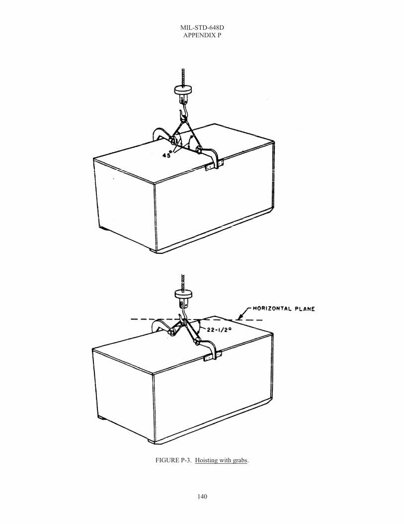
MIL-STD-648D APPENDIX P
140
FIGURE P-3. Hoisting with grabs.

MIL-STD-648D APPENDIX Q
141
MINIMIZATION OF HYDROGEN EMBRITTLEMENT IN PH 17-4/7 H900 COUPLED WITH ALUMINUM IN PHST CENTER DESIGNED EQUIPMENT
Q.1 SCOPE
Q.1.1 Scope. This appendix provides a minimization of hydrogen embrittlement in PH-17-4/7 H900 coupled with aluminum in PHST Center designed equipment. This appendix is not a mandatory part of the standard. The information contained herein is intended for guidance only.

MIL-STD-648D APPENDIX Q
142
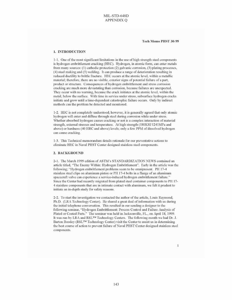
MIL-STD-648D APPENDIX Q
143

MIL-STD-648D APPENDIX Q
144

MIL-STD-648D
145
INDEX
A A-A-55057, 1, 17 access port, 4, 15, 21, 60, 76 acquisition requirements, 55 Acquisition, Technology & Logistics (AT&L), 32 AFR 80-18, 3, 12 Air Force containers, 49 aircraft jet, 43 aircraft propeller, 43 air-heat aging test, 44 alternate observation window location, 26 ambient (temperature), 8, 36, 41, 44, 50, 52, 53, 54, 101 AMC-R 700-103, 3, 11 American Lumber Standard Committee (ALSC), 20, 21 American Wood Preservers Association (AWPA), 5, 20 anthropometry, 2, 8, 34, 37 apparatus, 5, 87, 94, 97, 100, 101, 103, 108, 112, 116, 118,
120, 122, 125, 126, 127, 129, 130, 134 applicable documents, 1 AR 70-71, 3, 33 Army drawing 13222E3855, 5, 25 ASME B1.1, 5, 14 ASME B18.18.1M, 5, 19 ASME B18.5, 5, 19 ASME B18.9, 5, 19 Association of American Railroads (AAR), 38 ASTM A153/A153M, 5, 13 ASTM A380, 5, 21 ASTM A967, 5, 21 ASTM B117, 5, 21 ASTM B633, 5, 13 ASTM D1149, 6, 44 ASTM D2000, 6, 24 ASTM D257, 6, 19 ASTM D4003, 6, 38 ASTM D4577, 6, 45 ASTM D5276, 6, 37 ASTM D5277, 6, 38 ASTM D573, 6, 44 ASTM D642, 6, 45 ASTM D880, 6, 37, 120 ASTM D991, 6, 19 ASTM D996, 6, 8 ASTM D999, 6, 36 ASTM E162, 6, 47 ASTM E662, 6, 47 ASTM F1166, 6, 8, 27, 33 ASTM F1667, 6, 17 ASTM International, 5 automatic identification technology (AIT), 32
B bags, 24, 104, 131 blocking and bracing materials, 16 Book of Standards, 5, 20 breather valve, 25
built in test (BIT), 35 Bureau of Explosives (BOE), 38
C cadmium-plated hardware, 13 center lift, 3, 15, 31, 64 center of gravity (CG), 28, 29, 35, 104, 109, 113, 122, 136 chain tiedown assembly, 40, 41 chemical agent resistant coating (CARC, 14, 32, 33, 59 chemical agent resistant coating (CARC), 1 class I containers (foam or rubberized fiber isolation
systems, 40 class I containers (foam or rubberized fiber isolation
systems), 40 class II containers (resilient mount isolation systems), 40 classes of containers, 39 clean-room operations, 22 clinch, 8 clinched, 17 closed containers with auxiliary barriers, 23 closed containers without auxiliary barriers, 23 closure devices, 20, 22 closures (except removable head drums), 24 Code of Federal Regulations, 49 CFR 100-180,
Transportation, 8 color coding, 1, 33 Commercial Item Descriptions, 1 commercial-off-the-shelf (COTS), 8, 24 common standard parts for Navy containers, 15, 62 competent authority, 8, 11 conditioning, 87, 95, 96, 97, 98, 100, 101, 104, 105, 109,
110, 113, 114, 116, 117, 118, 119, 120, 121, 122, 123, 125, 127, 130, 133, 135
configuration, 6, 12, 26, 28, 31, 33, 34, 36, 38, 45, 48, 49, 58, 60
connected replenishment-at-sea (CONREP), 8, 11, 12, 28, 39, 55
container accessories, 25 container lift rings, 28 container markings, 33 container numerical unit (CNU) number, 32 container testing, 40 contents, 10, 11, 12, 15, 19, 20, 21, 22, 23, 25, 29, 32, 34,
35, 38, 39, 40, 41, 42, 44, 45, 49, 94, 95, 96, 97, 98, 100, 101, 102, 103, 104, 105, 108, 109, 110, 112, 113, 114, 116, 117, 118, 120, 121, 122, 123, 125, 127, 129, 130, 132, 133, 135, 136, 137
contents of container, 95, 97, 100, 104, 109, 113, 116, 118, 120, 122, 125, 130, 135
conveying, 134, 137 copper naphthenate, 20 cornerwise-drop (rotational) test, 37 corrosion, 7, 13, 14, 21, 24, 32 cracking pressure (relief valve), 8 cube and weight, 12 cunapsol 5, 20 cushion (compressive) creep, 8, 19 cylindrical containers, 37, 104, 113

MIL-STD-648D INDEX
146
D deck-stowed containers, 40 definitions, 8, 94, 97, 100, 103, 108, 112, 118, 129, 134 Department of Defense, 1, 2, 3, 5, 6, 7, 8, 10, 12, 20 Department of Transportation (DOT), 8, 11, 12 desiccant storage, 24 desiccator, 4, 15, 24, 80 design criteria, 23, 40 detailed requirements, 34 development and operational test and evaluation (DT&E
and OT&E), 12 dimensional/dynamic inert missiles (DIMs), 35 dissimilar metals, 2, 14 distributed isolation material (DIM), 8, 39 distributed load, 26 distribution network, 12 DLAR 4145.37, 3, 11 DOD 5100.76-M, 3, 12 DOD-HDBK-743, 2, 8 drainage, 21, 23 drawings, 2, 3, 4, 10, 15, 21, 60, 62, 120 drop height, 34, 37, 105, 106, 110, 114 drop surface recommendation, 36 drop test (free-fall), 37, 41 DSAR 4500.25, 3, 12 dynamic characteristics, 20
E edgewise-drop (rotational) test, 37 EIA 649, 6, 12 elastomer, 8, 14, 36 elastomeric parts, 14 electrode, 93 Electronic Industries Alliance (EIA), 6, 12 electrostatic detector, 92 electrostatic properties, 87 electrostatic test, 87, 89, 90, 91 electrostatic test arrangement, 90 electrostatic test chamber, 87, 89 endlift extrusion, 31 energy absorbing devices, 8, 34 Environmental Protection Agency (EPA), 13, 32 Environmental Protection Agency (EPA) 40 CFR 261.24,
13 ethylene oxide, 25 Executive Order 12196, 5, 13 expected temperature extremes, 36 explosive limit, 8 external air transport (EAT), 28
F faying surfaces, 8, 21 federal specifications, 10 federal standards, 1 FED-STD-H28, 1, 14 field-force protection, 32 fire performance requirements, 47 fit and compatibility, 34 fixture, 40, 47, 125
flame spread index test, 47 flexible barriers, 8, 22 floating shock platform (FSP), 40 fork pocket, 4, 7, 15, 29, 31, 71, 72 forklift handling, 29, 134 forklift truck (fully captive fork tine enclosures)
compatibility test, 47 forklift truck compatibility, 29 fragility levels, 9, 20, 35, 41 free-fall drop test, 105, 107, 108, 112 fuel air explosive (FAE), 25
G galling, 9, 21 general, 1, 5, 8, 10, 11, 12, 23, 25, 26, 34, 40, 41, 43, 44,
45, 46, 47, 55 Government documents, 1, 2 grades of containers, 39
H Handbook for Dynamic Data Acquisition and Analysis, 7 handbooks, 1, 2 handhold characteristics, 27 handle, 4, 15, 27, 34, 46, 53, 74, 77, 134 handle characteristics, 27 handlift truck MK 45, 47 handlift truck MK 45 compatibility, 47 handling, 1, 3, 4, 7, 9, 10, 11, 12, 13, 15, 22, 26, 27, 28, 29,
30, 31, 32, 34, 35, 37, 39, 41, 42, 45, 46, 47, 49, 55, 56, 57, 94, 96, 97, 98, 102, 103, 105, 108, 109, 112, 113, 117, 118, 119, 121, 123, 134, 135, 137
handling equipment, 1, 11, 12, 15, 29, 34, 46, 55, 134, 137 handling provision maintainability, 31 hazardous materials and devices, 11 hazards of electromagnetic radiation to ordnance (HERO),
32, 60 hazards of electromagnetic radiation to personnel (HERP),
32 heavyweight shock test, 40 height of free-fall drops for containers of various sizes and
weights, 106 height of rotational drops for containers of various sizes
and weights, 110, 114 high energy radio frequency (HERF), 32 hoisting, 4, 26, 28, 29, 33, 45, 46, 51, 54, 57, 65, 134, 135,
136, 139, 140 hoisting fitting and tiedown attachment points, 45 hoisting fittings strength test, 46 hoisting provisions, 28, 29, 46 hoisting with grabs, 134, 136, 140 hoisting with sling attachment provisions, 139 hoisting with slings, 134, 135 hot water technique, 129, 131, 133 Human factors engineering, 33 human systems integration (HSI), 9, 27, 33 humidity indicator, 4, 15, 24, 25, 33, 68 hydraulic pressure technique, 129, 132, 133 hydrogen embrittlement, 9, 13, 141 hygroscopic, 9, 15
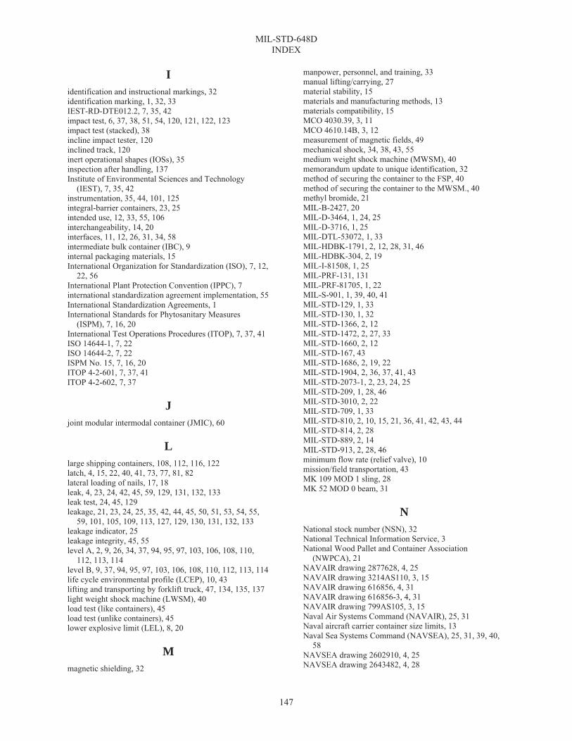
MIL-STD-648D INDEX
147
I identification and instructional markings, 32 identification marking, 1, 32, 33 IEST-RD-DTE012.2, 7, 35, 42 impact test, 6, 37, 38, 51, 54, 120, 121, 122, 123 impact test (stacked), 38 incline impact tester, 120 inclined track, 120 inert operational shapes (IOSs), 35 inspection after handling, 137 Institute of Environmental Sciences and Technology
(IEST), 7, 35, 42 instrumentation, 35, 44, 101, 125 integral-barrier containers, 23, 25 intended use, 12, 33, 55, 106 interchangeability, 14, 20 interfaces, 11, 12, 26, 31, 34, 58 intermediate bulk container (IBC), 9 internal packaging materials, 15 International Organization for Standardization (ISO), 7, 12,
22, 56 International Plant Protection Convention (IPPC), 7 international standardization agreement implementation, 55 International Standardization Agreements, 1 International Standards for Phytosanitary Measures
(ISPM), 7, 16, 20 International Test Operations Procedures (ITOP), 7, 37, 41 ISO 14644-1, 7, 22 ISO 14644-2, 7, 22 ISPM No. 15, 7, 16, 20 ITOP 4-2-601, 7, 37, 41 ITOP 4-2-602, 7, 37
J joint modular intermodal container (JMIC), 60
L large shipping containers, 108, 112, 116, 122 latch, 4, 15, 22, 40, 41, 73, 77, 81, 82 lateral loading of nails, 17, 18 leak, 4, 23, 24, 42, 45, 59, 129, 131, 132, 133 leak test, 24, 45, 129 leakage, 21, 23, 24, 25, 35, 42, 44, 45, 50, 51, 53, 54, 55,
59, 101, 105, 109, 113, 127, 129, 130, 131, 132, 133 leakage indicator, 25 leakage integrity, 45, 55 level A, 2, 9, 26, 34, 37, 94, 95, 97, 103, 106, 108, 110,
112, 113, 114 level B, 9, 37, 94, 95, 97, 103, 106, 108, 110, 112, 113, 114 life cycle environmental profile (LCEP), 10, 43 lifting and transporting by forklift truck, 47, 134, 135, 137 light weight shock machine (LWSM), 40 load test (like containers), 45 load test (unlike containers), 45 lower explosive limit (LEL), 8, 20
M magnetic shielding, 32
manpower, personnel, and training, 33 manual lifting/carrying, 27 material stability, 15 materials and manufacturing methods, 13 materials compatibility, 15 MCO 4030.39, 3, 11 MCO 4610.14B, 3, 12 measurement of magnetic fields, 49 mechanical shock, 34, 38, 43, 55 medium weight shock machine (MWSM), 40 memorandum update to unique identification, 32 method of securing the container to the FSP, 40 method of securing the container to the MWSM., 40 methyl bromide, 21 MIL-B-2427, 20 MIL-D-3464, 1, 24, 25 MIL-D-3716, 1, 25 MIL-DTL-53072, 1, 33 MIL-HDBK-1791, 2, 12, 28, 31, 46 MIL-HDBK-304, 2, 19 MIL-I-81508, 1, 25 MIL-PRF-131, 131 MIL-PRF-81705, 1, 22 MIL-S-901, 1, 39, 40, 41 MIL-STD-129, 1, 33 MIL-STD-130, 1, 32 MIL-STD-1366, 2, 12 MIL-STD-1472, 2, 27, 33 MIL-STD-1660, 2, 12 MIL-STD-167, 43 MIL-STD-1686, 2, 19, 22 MIL-STD-1904, 2, 36, 37, 41, 43 MIL-STD-2073-1, 2, 23, 24, 25 MIL-STD-209, 1, 28, 46 MIL-STD-3010, 2, 22 MIL-STD-709, 1, 33 MIL-STD-810, 2, 10, 15, 21, 36, 41, 42, 43, 44 MIL-STD-814, 2, 28 MIL-STD-889, 2, 14 MIL-STD-913, 2, 28, 46 minimum flow rate (relief valve), 10 mission/field transportation, 43 MK 109 MOD 1 sling, 28 MK 52 MOD 0 beam, 31
N National stock number (NSN), 32 National Technical Information Service, 3 National Wood Pallet and Container Association
(NWPCA), 21 NAVAIR drawing 2877628, 4, 25 NAVAIR drawing 3214AS110, 3, 15 NAVAIR drawing 616856, 4, 31 NAVAIR drawing 616856-3, 4, 31 NAVAIR drawing 799AS105, 3, 15 Naval Air Systems Command (NAVAIR), 25, 31 Naval aircraft carrier container size limits, 13 Naval Sea Systems Command (NAVSEA), 25, 31, 39, 40,
58 NAVSEA drawing 2602910, 4, 25 NAVSEA drawing 2643482, 4, 28

MIL-STD-648D INDEX
148
NAVSEA drawing 2644390, 4, 28 NAVSEA drawing 5166322, 4, 15 NAVSEA drawing 5166628, 4, 15 NAVSEA drawing 5167399, 4, 15 NAVSEA drawing 5167401, 4, 15 NAVSEA drawing 5167555, 4, 28 NAVSEA drawing 5167633, 4, 15, 71 NAVSEA drawing 5167693, 4, 15, 72 NAVSEA drawing 5167756, 4, 15 NAVSEA drawing 6212630, 4, 15 NAVSEA drawing 6212706, 4, 15 NAVSEA drawing 6212707, 4, 15 NAVSEA drawing 6212861, 4, 15 NAVSEA drawing 6212862, 4, 15 NAVSEA drawing 6212863, 4, 15 NAVSEA drawing 6212868, 4, 15 NAVSEA drawing 6213102, 4, 15 NAVSEA drawing 6214131, 4, 31, 84, 85, 86 NAVSUPINST 4030.50, 3, 11 nematode, 10 non-Government publications, 5 nonmetallic materials, 21 non-person portable container, 10, 37 North Atlantic Treaty Organization (NATO), 10, 13, 15 notes, 15, 33, 39, 50, 53, 54, 55, 88, 96, 98, 102, 105, 106,
110, 114, 117, 119, 121, 123, 128, 133, 137 nuclear, biological, chemical (NBC) survivability, 3, 32, 33 number and direction of tipover, 116, 117 number and height of drops, 109, 110, 113, 114, 123
O observation window, 15, 25, 26, 33, 75 Occupational Safety and Health Act (OSHA) Public Law
91-596, 13 Occupational Safety and Health Administration (OSHA), 4,
32 octave, 44, 125, 126, 127 OPNAVINST 4600.22A, 3, 12 order of precedence, 7 other Government documents, drawings, and publications,
2 ozone resistance test, 44
P packing, 9, 21, 22, 25, 49, 94, 95, 96, 97, 98, 100, 103, 104,
105, 108, 109, 110, 112, 113, 114, 116, 117, 118, 120, 121, 122, 123, 125, 135, 137
painting requirements, 32 pallet jack, 15, 30, 34 pallet jack compatibility, 30, 34 pass-fail criteria, 39 pendulum-impact test, 37, 122, 123, 124 performance oriented packaging (POP), 11, 26, 45, 53, 54,
60 personnel survivability, 9, 34 PH 17-4/7, 14, 21, 141 platform, 10, 40, 41, 100, 101, 122, 125, 126, 127 plating, 13, 32 pneumatic pressure technique, 129, 131, 133 PQ56, 20
preservation, 9, 20, 22, 23, 94, 103, 108, 112, 118 pressure test, 44, 45, 53, 54 pressurizing fitting, 24, 44, 45 procedure, 37, 38, 45, 46, 87, 88, 95, 97, 98, 100, 101, 103,
104, 105, 109, 113, 116, 118, 119, 120, 121, 122, 123, 125, 126, 127, 130, 133, 135, 137
propylene oxide, 25 protecting and identifying the container, 32 protection of contents against corrosion and water damage,
23 pushing, 47, 134, 136 pushing test, 136
R radio frequency identification (RFID), 32, 61 railcar shock test for nuclear weapon containers, 41 random vibration, 41, 42, 43, 60 records receptacle, 21, 25, 32 rectangular containers, 37, 104, 113 repetitive shock test, 36, 50, 51, 53, 54 repetitive shock test (stacked), 36 report, 88, 95, 96, 98, 101, 105, 109, 110, 113, 114, 116,
117, 118, 121, 123, 127, 133, 135, 137 reseal pressure (relief valve), 10 resilient mounts, 8, 20, 36, 39 resonance survey and dwell test, 44 restraining devices, 34, 100, 101 rings, container lift, 15 rolling test, 47
S SAE AMS2700, 7, 21 SAE AMS3269, 7, 21 SAE AMS3281, 7, 21 SAE AS26860, 7, 15, 24 SAE AS27166, 7, 15, 25 SAE AS5017, 7, 15, 24 SAE AS5135, 7, 15 SAE AS5389, 7, 15, 30, 31, 34 SAE AS8879, 7, 14 safety drop test, 41, 45 salt fog test, 44 scope, 1, 56, 62, 87, 94, 97, 100, 103, 108, 112, 116, 117,
118, 120, 122, 125, 129, 134, 141 screw threads, 5, 7, 14 security seal, 22, 23, 60 selection of technique, 133 sensitive materials (transportation security), 12 shackle, 4, 15, 28, 78 shipboard handling, 28, 31 shipboard shock test, 39, 41 shipboard shock test (eligibility), 41 ship-surface ship, 43 shock, 1, 8, 9, 10, 14, 18, 19, 20, 22, 29, 34, 35, 36, 39, 40,
41, 44, 45, 47, 53, 55, 56, 60, 94, 100, 101, 103, 104, 105, 108, 109, 112, 113
shock mount aging, 44 shock response spectrum (SRS), 10, 35 shock test, 1, 29, 34, 36, 39, 40, 41, 47, 53 shock test for containers-at-sea, 39

MIL-STD-648D INDEX
149
simulated rainfall technique, 129, 132, 133 single hoisting fitting strength test, 46 sinusoidal cycling test, 44 sinusoidal testing, 42, 43 size limitations, 40 skids, 29, 41, 47, 95, 103, 108, 112, 136 sling handling with attachments, 136 slings placed around specimen with load superimposed,
138 smoke density test, 47 special protection devices, 32 special requirements for controlled-breathing integral-
barrier containers, 25 special requirements for free-breathing containers, 25 specialized shipping container, 1, 10, 11, 12, 16, 26, 28, 29,
33 Specialized shipping container, 1 specifications, standards, and handbooks, 1 specimen, 87, 88, 95, 97, 98, 100, 101, 104, 109, 110, 113,
116, 118, 120, 122, 125, 126, 127, 129, 130, 131, 132, 133, 134, 135, 136, 137
springwood, 10, 18 squeeze technique, 129, 131, 133 stackability, 26, 94 stacked container fire test, 48, 49 stacking and stowing, 26 stacking stability, 26 stacking strength, 26, 45 stainless steel, 5, 21 STANAG 2828, 1, 15, 55 STANAG 2829, 1, 15, 55 standard parts and materials, 10, 14 standard tension replenishment alongside method
(STREAM), 10, 39 standards, 1, 10, 13, 14, 32 static electricity, 22 static overload, 47 static technique, 132, 133 structural, 16, 23, 26, 41, 42, 44, 45, 46, 47, 95, 96, 98,
102, 105, 109, 113, 116, 117, 121, 123, 127, 137 structural integrity, 41, 44, 45, 46 subject term (key word) listing, 55 submersion (or immersion) techniques, 132 summerwood, 10, 18 support fasteners and closure devices, 20 sympathetic detonation, 10, 49
T Tech Memo No. PHST-30-99, 14, 21 Technical Report 93003, 3, 26 temperature combined with shock, 36 temperature control, 10, 32 test envelope 2 to 500 cycles per second for vibration
(sinusoidal motion) test, 128 test environment, 87 test loads, 35, 41 test pressures, 45 test procedure, 2, 105, 137 test specimen, 88, 95, 97, 100, 104, 105, 109, 113, 116,
118, 120, 122, 125, 126, 130, 135
testing, 6, 7, 11, 13, 15, 20, 21, 22, 24, 25, 26, 34, 35, 36, 39, 40, 41, 42, 43, 44, 45, 49, 55, 60, 87, 94, 100, 118, 120, 125
testing orientations, 40 testing to hi-shock events, 41 tiedown, 1, 2, 26, 27, 28, 29, 31, 33, 40, 41, 46, 51, 54, 57 tiedown strength test, 46 tipover test, 37, 51, 106, 116, 117, 119 TOP 8-2-111, 3, 33 top dunnage, 94, 96, 97 top superimposed-load test, 94, 96, 97, 98, 99 towing, 47, 134, 136 towing test, 47, 136 transfer-at-sea, 9, 12, 28, 39, 55, 94, 103, 108, 112 transfer-at-sea shock test, 39 transmissibility, 11, 42, 44, 127 transparent window in auxiliary barrier, 25 transportability requirements, 12 truck transportation over U.S. highway, 43
U U.S. Army Nuclear and Chemical Agency (USANCA)
criteria, 33 Under Secretary of Defense (USD), 32 undersling handling, 135 underway replenishment at sea (UNREP), 11, 12, 55 unique identification (UID), 32, 61 unit load, 2, 6, 11, 12, 28, 31, 36, 39, 46, 47 unit load compatibility, 12 United States Army, 5 United States Department of Agriculture (USDA), 5, 16, 20 USDA Agriculture Handbook No. 72, 16
V vacuum chamber technique, 129, 130, 133 vacuum retention technique, 129, 130, 133 valve, breather, 4, 15, 79 ventilation, 23 vertical replenishment at sea (VERTREP), 11, 12, 28, 55 vibration, 6, 8, 9, 11, 20, 33, 41, 42, 43, 44, 45, 50, 51, 53,
54, 55, 56, 94, 100, 101, 103, 108, 112, 125, 126, 127
W weight limitations, 11, 12, 40 wide handle latch, 22 wood packaging material (WPM), 21 wood treatment and preservation, 20
Z zinc naphthenate, 20
MIL-STD-648D
150
Custodians: Preparing activity: Army – SM Navy – OS Navy – OS (Project PACK-2006-003) Air Force – 11 Review
activities: Army – AR, AT, AV, CR, CR3, MI, MT, TE, TM2Navy – AS, MC, SA, SH, YDAir Force – 13, 99
NOTE: The activities listed above were interested in this document as of the date of this document. Since or-ganizations and responsibilities can change, you should verify the currency of the information above using the ASSIST Online database at http://assist.daps.dla.mil.