Embed Size (px)
Citation preview
P a g e | 1 Network protocols DEPARTMENT OF CSE/RGCET
DEPARTMENT OF COMPUTER SCIENCE AND ENGINEERING
NETWORK PROTOCOLS
UNIT III(2 MARKS)
Network Layer Protocols: IP, IPv6, ICMP, ICMPv6, Mobile IP, OSPF, RIP, Multicasting protocols – BGMP, DVMRP, IGMP, and MPLS protocols.
1.Write about IP
The Internet Protocol (IP) is a network- layer (Layer 3 in the OSI model) protocol that contains
addressing information and some control information to enable packets to be routed in a network. IP is the primary network- layer protocol in the TCP/IP protocol suite. Along with the Transmission Control Protocol (TCP), IP represents the heart of the Internet protocols. IP is equally well suited for both LAN and WAN
communications.
2.Write down the responsibilities of IP
IP has two primary responsibilities: providing connectionless, best-effort delivery of datagram’s through a network; and providing fragmentation and reassembly of datagram’s to support data links with
different maximum-transmission unit (MTU) sizes.
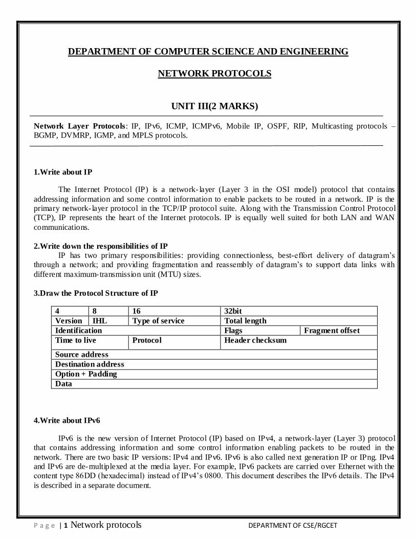
3.Draw the Protocol Structure of IP
4 8 16 32bit
Version IHL Type of service Total length
Identification Flags Fragment offset
Time to live Protocol Header checksum
Source address
Destination address
Option + Padding
Data
4.Write about IPv6
IPv6 is the new version of Internet Protocol (IP) based on IPv4, a network-layer (Layer 3) protocol that contains addressing information and some control information enabling packets to be routed in the
network. There are two basic IP versions: IPv4 and IPv6. IPv6 is also called next generation IP or IPng. IPv4 and IPv6 are de-multiplexed at the media layer. For example, IPv6 packets are carried over Ethernet with the content type 86DD (hexadecimal) instead of IPv4’s 0800. This document describes the IPv6 details. The IPv4
is described in a separate document.
P a g e | 2 Network protocols DEPARTMENT OF CSE/RGCET
5.Draw the Protocol Structure of IPV6
4 12 16 24 32bit
Version Priority Flow label
Identification Flags Fragment offset
Payload length Next header Hop limit
Source address(128 bits)
Destination address(128 bits)
6.Write about ICMP & ICMPv6
Internet Control Message Protocol (ICMP) is an integrated part of the IP suite. ICMP messages, delivered in IP packets, are used for out-of-band messages related to network operation or mis-operation.
ICMP packet delivery is unreliable, so hosts can’t count on receiving ICMP packets for any network problems. The key ICMP functions are:
7.Draw the Protocol Structure of ICMP
8 16 32bit
Type Code Checksum
Identifier Sequence number
Address mask
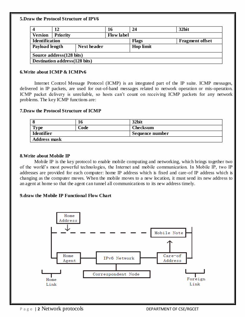
8.Write about Mobile IP
Mobile IP is the key protocol to enable mobile computing and networking, which brings together two of the world’s most powerful technologies, the Internet and mobile communication. In Mobile IP, two IP
addresses are provided for each computer: home IP address which is fixed and care-of IP address which is changing as the computer moves. When the mobile moves to a new location, it must send its new address to an agent at home so that the agent can tunnel all communications to its new address timely.
9.draw the Mobile IP Functional Flow Chart
P a g e | 3 Network protocols DEPARTMENT OF CSE/RGCET
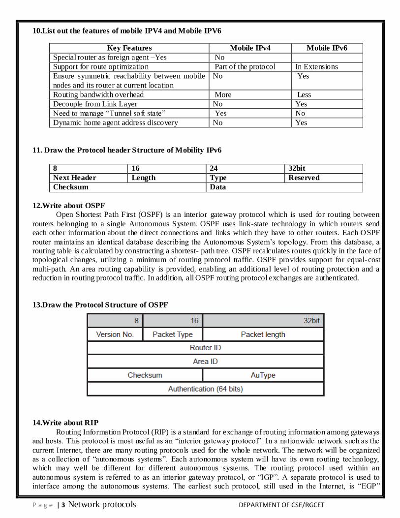
10.List out the features of mobile IPV4 and Mobile IPV6
Key Features Mobile IPv4 Mobile IPv6
Special router as foreign agent –Yes No
Support for route optimization Part of the protocol In Extensions
Ensure symmetric reachability between mobile
nodes and its router at current location
No Yes
Routing bandwidth overhead More Less
Decouple from Link Layer No Yes
Need to manage ―Tunnel soft state‖ Yes No
Dynamic home agent address discovery No Yes
11. Draw the Protocol header Structure of Mobility IPv6
8 16 24 32bit
Next Header Length Type Reserved
Checksum Data
12.Write about OSPF
Open Shortest Path First (OSPF) is an interior gateway protocol which is used for routing between
routers belonging to a single Autonomous System. OSPF uses link-state technology in which routers send each other information about the direct connections and links which they have to other routers. Each OSPF
router maintains an identical database describing the Autonomous System’s topology. From this database, a routing table is calculated by constructing a shortest- path tree. OSPF recalculates routes quickly in the face of topological changes, utilizing a minimum of routing protocol traffic. OSPF provides support for equal-cost
multi-path. An area routing capability is provided, enabling an additional level of routing protection and a reduction in routing protocol traffic. In addition, all OSPF routing protocol exchanges are authenticated.
13.Draw the Protocol Structure of OSPF
14.Write about RIP
Routing Information Protocol (RIP) is a standard for exchange of routing information among gateways and hosts. This protocol is most useful as an ―interior gateway protocol‖. In a nationwide network such as the
current Internet, there are many routing protocols used for the whole network. The network will be organized as a collection of ―autonomous systems‖. Each autonomous system will have its own routing technology, which may well be different for different autonomous systems. The routing protocol used within an
autonomous system is referred to as an interior gateway protocol, or ―IGP‖. A separate protocol is used to interface among the autonomous systems. The earliest such protocol, still used in the Internet, is ―EGP‖
P a g e | 4 Network protocols DEPARTMENT OF CSE/RGCET
(exterior gateway protocol). Such protocols are now usually referred to as inter-AS routing protocols. RIP is designed to work with moderate-size networks using reasonably homogeneous technology. Thus it is suitable
as an IGP for many campuses and for regional networks using serial lines whose speeds do not vary widely. It is not intended for use in more complex environments.
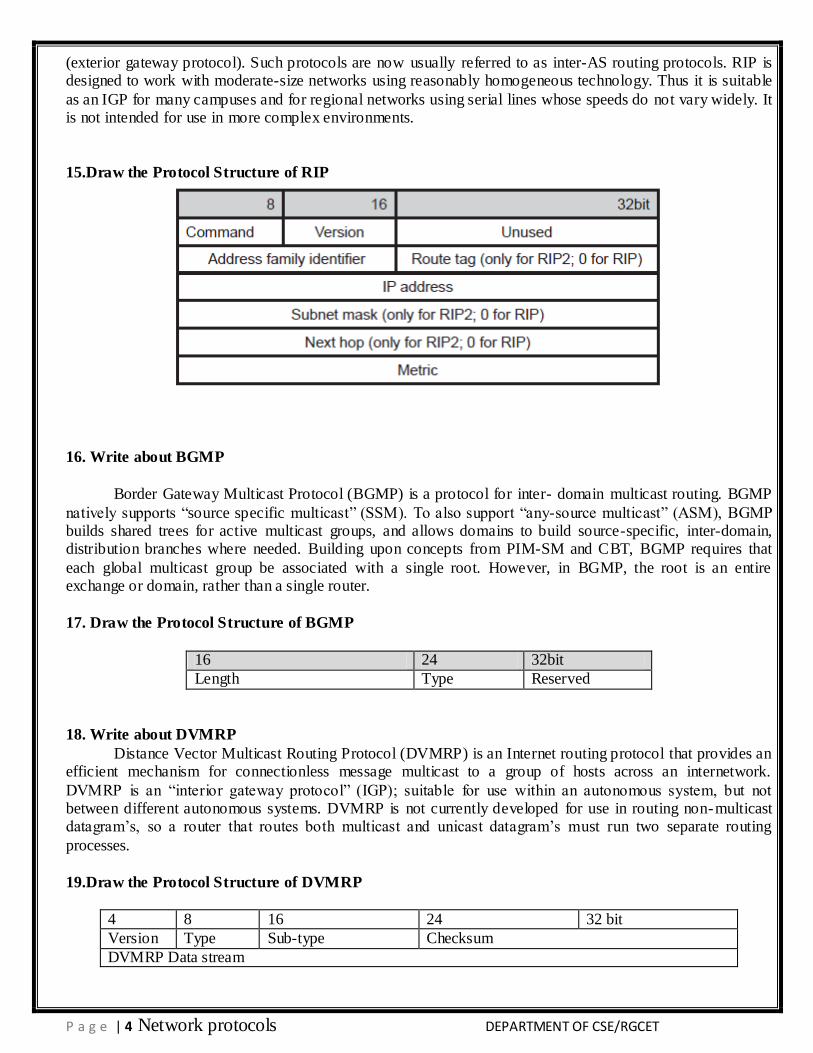
15.Draw the Protocol Structure of RIP
16. Write about BGMP
Border Gateway Multicast Protocol (BGMP) is a protocol for inter- domain multicast routing. BGMP
natively supports ―source specific multicast‖ (SSM). To also support ―any-source multicast‖ (ASM), BGMP builds shared trees for active multicast groups, and allows domains to build source-specific, inter-domain, distribution branches where needed. Building upon concepts from PIM-SM and CBT, BGMP requires that
each global multicast group be associated with a single root. However, in BGMP, the root is an entire exchange or domain, rather than a single router.
17. Draw the Protocol Structure of BGMP
16 24 32bit
Length Type Reserved
18. Write about DVMRP
Distance Vector Multicast Routing Protocol (DVMRP) is an Internet routing protocol that provides an efficient mechanism for connectionless message multicast to a group of hosts across an internetwork.
DVMRP is an ―interior gateway protocol‖ (IGP); suitable for use within an autonomous system, but not between different autonomous systems. DVMRP is not currently developed for use in routing non-multicast datagram’s, so a router that routes both multicast and unicast datagram’s must run two separate routing
processes.
19.Draw the Protocol Structure of DVMRP
4 8 16 24 32 bit
Version Type Sub-type Checksum
DVMRP Data stream
P a g e | 5 Network protocols DEPARTMENT OF CSE/RGCET
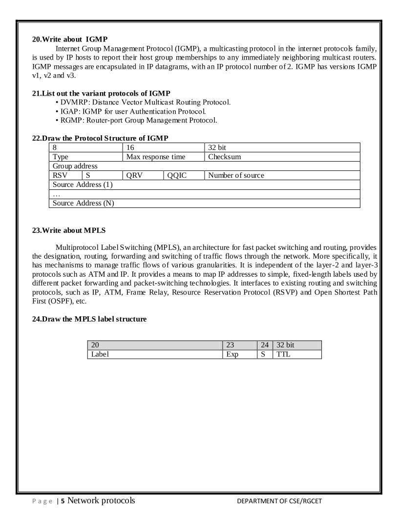
20.Write about IGMP
Internet Group Management Protocol (IGMP), a multicasting protocol in the internet protocols family, is used by IP hosts to report their host group memberships to any immediately neighboring multicast routers.
IGMP messages are encapsulated in IP datagrams, with an IP protocol number of 2. IGMP has versions IGMP v1, v2 and v3.
21.List out the variant protocols of IGMP
• DVMRP: Distance Vector Multicast Routing Protocol.
• IGAP: IGMP for user Authentication Protocol. • RGMP: Router-port Group Management Protocol.
22.Draw the Protocol Structure of IGMP
8 16 32 bit
Type Max response time Checksum
Group address
RSV S QRV QQIC Number of source
Source Address (1)
…
Source Address (N)
23.Write about MPLS
Multiprotocol Label Switching (MPLS), an architecture for fast packet switching and routing, provides the designation, routing, forwarding and switching of traffic flows through the network. More specifically, it has mechanisms to manage traffic flows of various granularities. It is independent of the layer-2 and layer-3
protocols such as ATM and IP. It provides a means to map IP addresses to simple, fixed-length labels used by different packet forwarding and packet-switching technologies. It interfaces to existing routing and switching
protocols, such as IP, ATM, Frame Relay, Resource Reservation Protocol (RSVP) and Open Shortest Path First (OSPF), etc.
24.Draw the MPLS label structure
20 23 24 32 bit
Label Exp S TTL
P a g e | 6 Network protocols DEPARTMENT OF CSE/RGCET
11 Marks
1. Explain in detail about Internet Protocol in detail?
Protocol Description
The Internet Protocol (IP) is a network- layer (Layer 3 in the OSI model) protocol that contains addressing information and some control information to enable packets to be routed in a network. IP is the primary network- layer protocol in the TCP/IP protocol suite. Along with the Transmission Control Protocol
(TCP), IP represents the heart of the Internet protocols. IP is equally well suited for both LAN and WAN communications.
IP has two primary responsibilities: providing connectionless, best-effort delivery of datagram’s through a network; and providing fragmentation and reassembly of datagram’s to support data links with different maximum-transmission unit (MTU) sizes. The IP addressing scheme is integral to the process of
routing IP datagram’s through an internetwork. Each IP address has specific components and follow s a basic format. These IP addresses can be subdivided and used to create addresses for subnetworks. Each computer
(known as a host) on a TCP/IP network is assigned a unique 32-bit logical address that is divided into two main parts: the network number and the host number. The network number identifies a network and must be assigned by the Internet Network Information Center (InterNIC) if the network is to be part of the Internet. An
Internet Service Provider (ISP) can obtain blocks of network addresses from the InterNIC and can itself assign address space as necessary. The host number identifies a host on a network and is assigned by the local
network administrator. When you send or receive data (for example, an e-mail note or a Web page), the message gets divided
into little chunks called packets. Each of these packets contains both the sender’s Internet address and the
receiver’s address. Because a message is divided into a number of packets, each packet can, if necessary, be sent by a different route across the Internet. Packets can arrive in a different order than the order they were
sent in. The Internet Protocol just delivers them. It’s up to another protocol, the Transmission Control Protocol (TCP) to put them back in the right order.
All other protocols within the TCP/IP suite, except ARP and RARP, use IP to route frames from host
to host. There are two basic IP versions, IPv4 and IPv6. This document describes the IPv4 details. The IPv6 details are described in a separate document.
Protocol Structure
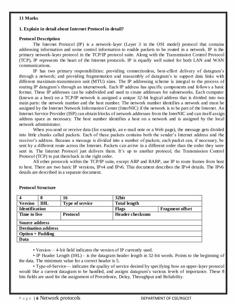
4 8 16 32bit
Version IHL Type of service Total length
Identification Flags Fragment offset
Time to live Protocol Header checksum
Source address
Destination address
Option + Padding
Data
• Version— 4-bit field indicates the version of IP currently used.
• IP Header Length (IHL) - is the datagram header length in 32-bit words. Points to the beginning of the data. The minimum value for a correct header is 5.
• Type-of-Service— indicates the quality of service desired by specifying how an upper- layer protocol would like a current datagram to be handled, and assigns datagram’s various levels of importance. These 8 bits fields are used for the assignment of Precedence, Delay, Throughput and Reliability.
P a g e | 7 Network protocols DEPARTMENT OF CSE/RGCET
• Total Length—specifies the length, in bytes, of the entire IP packet, including the data and header. The maximum length which can be specified by this field is 65,535 bytes. Typically, hosts are prepared to
accept datagram’s up to 576 bytes. • Identification—contains an integer that identifies the current datagram. This field is assigned by
sender to help receiver to assemble the datagram fragments. • Flags - consists of a 3-bit field of which the two low order (least-significant) bits control
fragmentation. The low-order bit specifies whether the packet can be fragmented. The middle bit specifies
whether the packet is the last fragment in a series of fragmented packets. The third or high-order bit is not used.
• Fragment Offset - This 13-bits field indicates the position of the fragment’s data relative to the beginning of the data in the original datagram, which allows the destination IP process to properly reconstruct the original datagram.
• Time-to-Live - is a counter that gradually decrements down to zero, at which point the datagram is discarded. This keeps packets from looping endlessly.
• Protocol - indicates which upper-layer protocol receives incoming packets after IP processing is complete.
• Header Checksum—helps ensure IP header integrity. Since some header fields change, e.g., Time to
Live, this is recomputed and verified at each point the Internet header is processed. • Source Address—specifies the sending node.
• Destination Address—specifies the receiving node. • Options—allows IP to support various options, such as security. • Data—contains upper-layer information.
2. Explain in detail about Internet Protocol version 6(11 marks)
Protocol Description
IPv6 is the new version of Internet Protocol (IP) based on IPv4, a network-layer (Layer 3) protocol
that contains addressing information and some control information enabling packets to be routed in the network. There are two basic IP versions: IPv4 and IPv6. IPv6 is also called next generation IP or IPng. IPv4 and IPv6 are de-multiplexed at the media layer. For example, IPv6 packets are carried over Ethernet with the
content type 86DD (hexadecimal) instead of IPv4’s 0800. This document describes the IPv6 details. The IPv4 is described in a separate document.
IPv6 increases the IP address size from 32 bits to 128 bits, to support more levels of addressing hierarchy, a much greater number of addressable nodes and simpler auto-configuration of addresses. IPv6 addresses are expressed in hexadecimal format (base 16) which allows not only numerals (0-9) but a few
characters as well (a- f). A sample ipv6 address looks like:3ffe:ffff:100:f101:210:a4ff:fee3:9566. Scalability of multicast addresses is introduced. A new type of address called an anycast address is also defined, to send a
packet to any one of a group of nodes. Two major improvements in IPv6 vs. v4: • Improved support for extensions and options - IPv6 options are placed in separate headers that are
located between the IPv6 header and the transport layer header. Changes in the way IP header options are
encoded allow more efficient forwarding, less stringent limits on the length of options, and greater flexibility for introducing new options in the future. The extension headers are: Hop-by-Hop Option, Routing (Type 0),
Fragment, Destination Option, Authentication, and Encapsulation Payload. • Flow labeling capability - A new capability has been added to enable the labeling of packets
belonging to particular traffic flows for which the sender requests special handling, such as non-default
Quality of Service or real time service.
Protocol Structure
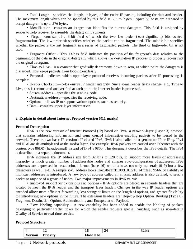
4 12 16 24 32bit
Version Priority Flow label
P a g e | 8 Network protocols DEPARTMENT OF CSE/RGCET
Identification Flags Fragment offset
Payload length Next header Hop limit
Source address(128 bits)
Destination address(128 bits)
• Version – 4-bit Internet Protocol Version number (IPv6 is 6).
• Priority -- 8-bit traffic class field enables a source to identify the desired delivery priority of the packets. Priority values are divided into ranges: traffic where the source provides congestion control and non-
congestion control traffic. • Flow label -- 20-bit flow label is used by a source to label those products for which it requests special
handling by the IPv6 router. The flow is uniquely identified by the combination of a source address and a non-
zero flow label. • Payload length -- 16-bit integer in octets is the length of payload including header.
• Next header – 8-bit selector identifies the type of header immediately following the IPv6 header. • Hop limit -- 8-bit integer that is decremented by one by each node that forwards the packet. The
packet is discarded if the Hop Limit is decremented to zero.
• Source address -- 128-bit address of the originator of the packet. • Destination address -- 128-bit address of the intended recipient of the packet (possibly not the
ultimate recipient, if a Routing header is present). 3. Explain in detail about Internet Message Control Protocol and ICMP version 6(6marks)
Protocol Description
Internet Control Message Protocol (ICMP) is an integrated part of the IP suite. ICMP messages,
delivered in IP packets, are used for out-of-band messages related to network operation or mis-operation. ICMP packet delivery is unreliable, so hosts can’t count on receiving ICMP packets for any network
problems. The key ICMP functions are: • Announce network errors, such as a host or entire po rtion of the network being unreachable, due to
some type of failure. A TCP or UDP packet directed at a port number with no receiver attached is also
reported via ICMP. • Announce network congestion. When a router begins buffering too many packets, due to an inability
to transmit them as fast as they are being received, it will generate ICMP Source Quench messages. Directed at the sender, these messages should cause the rate of packet transmission to be slowed. Of course, generating too many Source Quench messages would cause even more network congestion, so they are used sparingly.
• Assist Troubleshooting. ICMP supports an Echo function, which just sends a packet on a round--trip between two hosts. Ping, a common network management tool, is based on this feature. Ping will transmit a
series of packets, measuring average round--trip times and computing loss percentages. • Announce Timeouts. If an IP packet’s TTL field drops to zero, the router discarding the packet will
often generate an ICMP packet announcing this fact. Trace Route is a tool which maps network routes by
sending packets with small TTL values and watching the ICMP timeout announcements. The Internet Control Message Protocol (ICMP) was revised during the definition of IPv6. In addition, the multicast control functions of the IPv4 Group Membership Protocol (IGMP) are now incorporated in the ICMPv6.
Protocol Structure
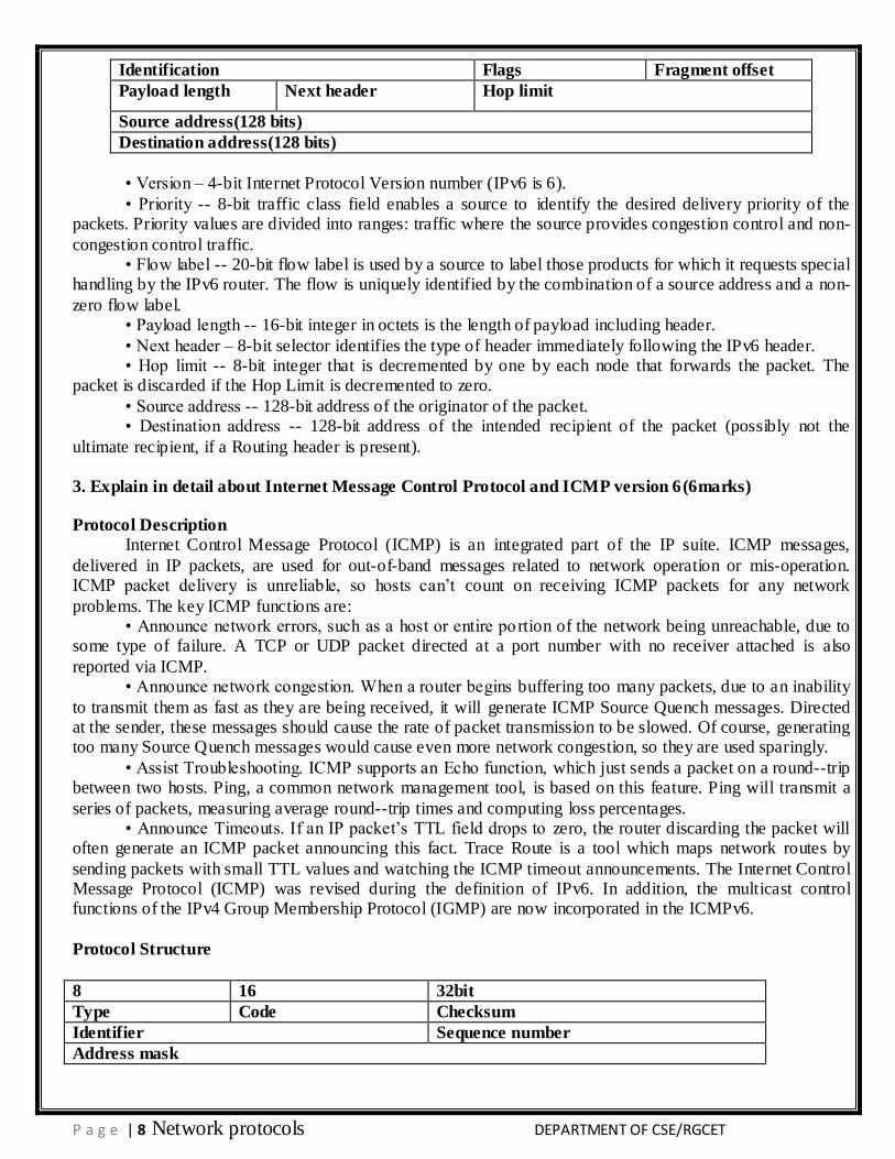
8 16 32bit
Type Code Checksum
Identifier Sequence number
Address mask
P a g e | 9 Network protocols DEPARTMENT OF CSE/RGCET
• Type -- Messages can be error or informational messages. Error messages can be Destination unreachable, Packet too big, Time exceed, Parameter problem. The possible informational messages are, Echo
Request, Echo Reply, Group Membership Query, Group Membership Report, and Group Membership Reduction.
• Code -- For each type of message several different codes are defined. An example of this is the Destination Unreachable message, where possible messages are: no route to destination, communication with destination administratively prohibited, not a neighbor, address unreachable, port unreachable. For further
details, refer to the standard. • Checksum -- The 16-bit one’s complement of the one’s complement sum of the ICMP message
starting with the ICMP Type. For computing the checksum, the checksum field should be zero. • Identifier -- An identifier to aid in matching requests/ replies; may be zero. • Sequence number -- Sequence number to aid in matching requests/replies; may be zero.
• Address mask -- A 32-bit mask.
4. Write in detail IP Mobility Support Protocol for IPv4 & IPv6(6 marks)
Protocol Description
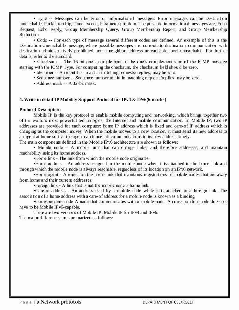
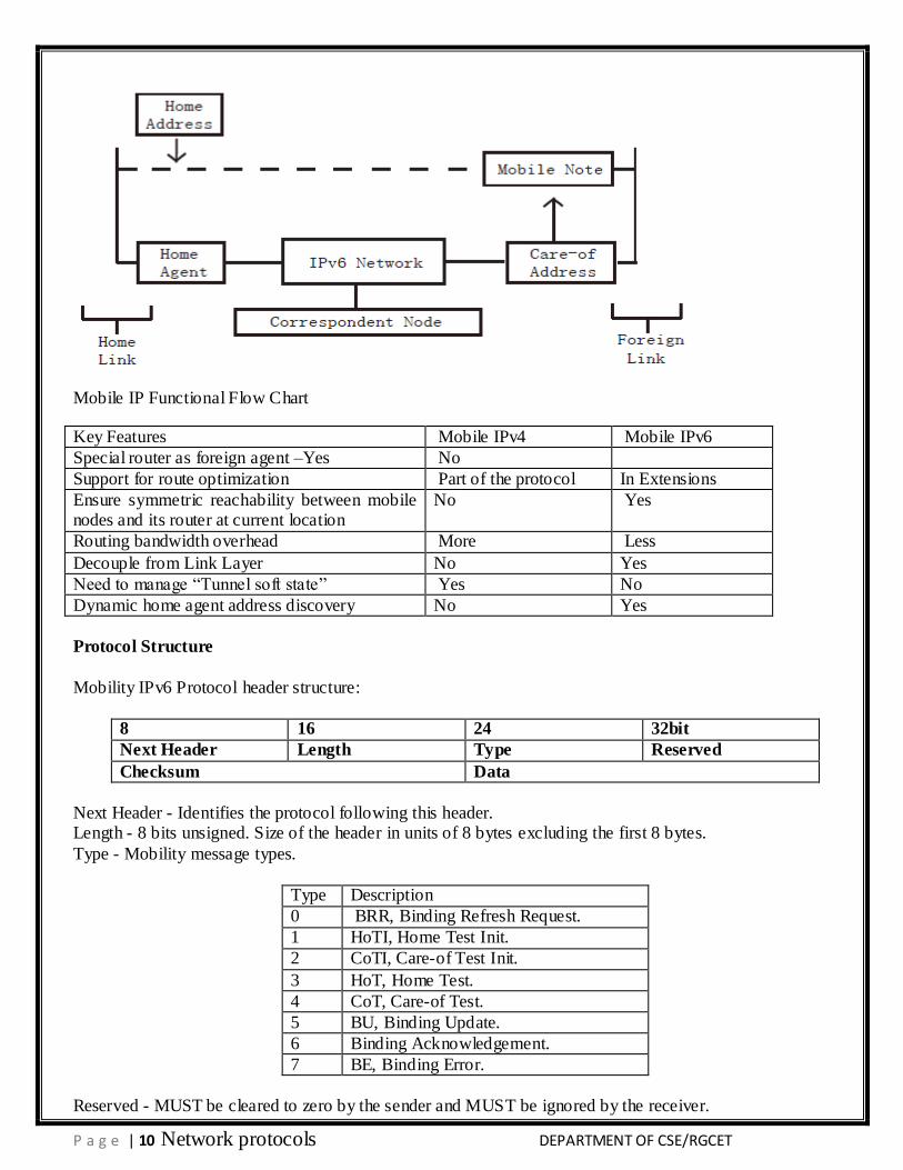
Mobile IP is the key protocol to enable mobile computing and networking, which brings together two of the world’s most powerful technologies, the Internet and mobile communication. In Mobile IP, two IP
addresses are provided for each computer: home IP address which is fixed and care-of IP address which is changing as the computer moves. When the mobile moves to a new location, it must send its new address to an agent at home so that the agent can tunnel all communications to its new address timely.
The main components defined in the Mobile IPv6 architecture are shown as follows: • Mobile node – A mobile unit that can change links, and therefore addresses, and maintain
reachability using its home address. •Home link - The link from which the mobile node originates. •Home address - An address assigned to the mobile node when it is attached to the home link and
through which the mobile node is always reachable, regardless of its location on an IPv6 network. •Home agent - A router on the home link that maintains registrations of mobile nodes that are away
from home and their current addresses. •Foreign link - A link that is not the mobile node’s home link. •Care-of address - An address used by a mobile node while it is attached to a foreign link. The
association of a home address with a care-of address for a mobile node is known as a binding. •Correspondent node A node that communicates with a mobile node. A correspondent node does not
have to be Mobile IPv6-capable. There are two versions of Mobile IP: Mobile IP for IPv4 and IPv6.
The major differences are summarized as follows:
P a g e | 10 Network protocols DEPARTMENT OF CSE/RGCET
Mobile IP Functional Flow Chart
Key Features Mobile IPv4 Mobile IPv6
Special router as foreign agent –Yes No
Support for route optimization Part of the protocol In Extensions
Ensure symmetric reachability between mobile nodes and its router at current location
No Yes
Routing bandwidth overhead More Less
Decouple from Link Layer No Yes
Need to manage ―Tunnel soft state‖ Yes No
Dynamic home agent address discovery No Yes
Protocol Structure
Mobility IPv6 Protocol header structure:
8 16 24 32bit
Next Header Length Type Reserved
Checksum Data
Next Header - Identifies the protocol following this header. Length - 8 bits unsigned. Size of the header in units of 8 bytes excluding the first 8 bytes.
Type - Mobility message types.
Type Description
0 BRR, Binding Refresh Request.
1 HoTI, Home Test Init.
2 CoTI, Care-of Test Init.
3 HoT, Home Test.
4 CoT, Care-of Test.
5 BU, Binding Update.
6 Binding Acknowledgement.
7 BE, Binding Error.
Reserved - MUST be cleared to zero by the sender and MUST be ignored by the receiver.
P a g e | 11 Network protocols DEPARTMENT OF CSE/RGCET
Checksum - The 16 bit one’s complement checksum of the Mobility Header. Data - Variable length.
5. Write in detail Open Shortest Path First protocol (11 marks)
Protocol Description
Open Shortest Path First (OSPF) is an interior gateway protocol which is used for routing between routers belonging to a single Autonomous System. OSPF uses link-state technology in which routers send
each other information about the direct connections and links which they have to other routers. Each OSPF router maintains an identical database describing the Autonomous System’s topology. From this database, a
routing table is calculated by constructing a shortest- path tree. OSPF recalculates routes quickly in the face of topological changes, utilizing a minimum of routing protocol traffic. OSPF provides support for equal-cost multi-path. An area routing capability is provided, enabling an additional level of routing protection and a
reduction in routing protocol traffic. In addition, all OSPF routing protocol exchanges are authenticated. OSPF has been designed expressly for the TCP/IP internet environment, including explicit support for
CIDR and the tagging of externally-derived routing information. OSPF also provides for the authentication of routing updates and utilizes IP multicast when sending/receiving the updates.
OSPF routes IP packets based solely on the destination IP address found in the IP packet header. IP
packets are routed ―as is‖; they are not encapsulated in any further protocol headers as they transit the Autonomous System.
OSPF allows sets of networks to be grouped together. Such a grouping is called an area. The topology of an area is hidden from the rest of the Autonomous System. This information hiding enables a significant reduction in routing traffic. Also, routing within the area is determined only by the area’s own topology,
lending the area protection from bad routing data. OSPF enables the flexible configuration of IP subnets. Each route distributed by OSPF has a
destination and mask. Two different subnets of the same IP network number may have different sizes (i.e., different masks). This is commonly referred to as variable length subnetting. A packet is routed to the best (i.e., longest or most specific) match.
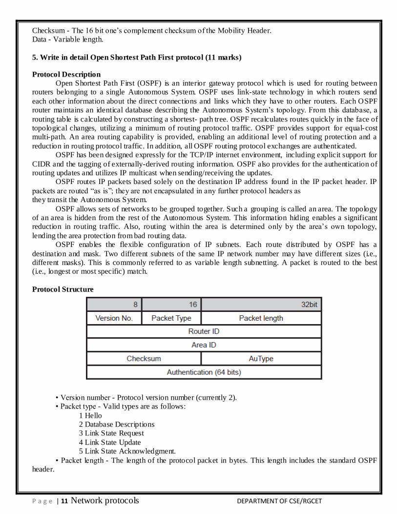
Protocol Structure
• Version number - Protocol version number (currently 2). • Packet type - Valid types are as follows:
1 Hello 2 Database Descriptions 3 Link State Request
4 Link State Update 5 Link State Acknowledgment.
• Packet length - The length of the protocol packet in bytes. This length includes the standard OSPF header.
P a g e | 12 Network protocols DEPARTMENT OF CSE/RGCET
• Router ID - The router ID of the packet’s source. In OSPF, the source and destination of a routing protocol packet are the two ends of a (potential) adjacency.
• Area ID - identifying the area that this packet belongs to. All OSPF packets are associated with a single area. Most travel a single hop only.
• Checksum - The standard IP checksum of the entire contents of the packet, starting with the OSPF packet header but excluding the 64-bit authentication field.
• AuType - Identifies the authentication scheme to be used for the packet.
• Authentication - A 64-bit field for use by the authentication scheme.
6. Write in detail Routing Information Protocol (6 marks)
Protocol Description
Routing Information Protocol (RIP) is a standard for exchange of routing information among gateways
and hosts. This protocol is most useful as an ―interior gateway protocol‖. In a nationwide network such as the current Internet, there are many routing protocols used for the whole network. The network will be organized
as a collection of ―autonomous systems‖. Each autonomous system will have its own routing technology, which may well be different for different autonomous systems. The routing protocol used within an autonomous system is referred to as an interior gateway protocol, or ―IGP‖. A separate protocol is used to
interface among the autonomous systems. The earliest such protocol, still used in the Internet, is ―EGP‖ (exterior gateway protocol). Such protocols are now usually referred to as inter-AS routing protocols. RIP is
designed to work with moderate-size networks using reasonably homogeneous technology. Thus it is suitable as an IGP for many campuses and for regional networks using serial lines whose speeds do not vary widely. It is not intended for use in more complex environments.
RIP2, derives from RIP, is an extension of the Routing Information Protocol (RIP) intended to expand the amount of useful information carried in the RIP2 messages and to add a measure of security. RIP2 is a
UDP-based protocol. Each host that uses RIP2 has a routing process that sends and receives datagram’s on UDP port number 520.
RIP and RIP2 are for the IPv4 network while the RIPng is designed for the IPv6 network. In this
document, the details of RIP and RIP2 will be described.
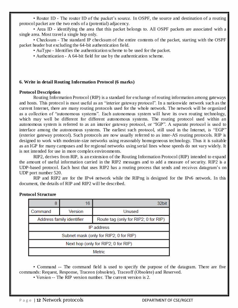
Protocol Structure
• Command -- The command field is used to specify the purpose of the datagram. There are five commands: Request, Response, Traceon (obsolete), Traceoff (Obsolete) and Reserved.
• Version -- The RIP version number. The current version is 2.
P a g e | 13 Network protocols DEPARTMENT OF CSE/RGCET
• Address family identifier -- Indicates what type of address is specified in this particular entry. This is used because RIP2 may carry routing information for several different protocols. The address family
identifier for IP is 2. • Route tag -- Attribute assigned to a route which must be preserved and readvertised with a route. The
route tag provides a method of separating internal RIP routes (routes for networks within the RIP routing domain) from external RIP routes, which may have been imported from an EGP or another IGP.
• IP address -- The destination IP address.
• Subnet mask -- Value applied to the IP address to yield the non-host portion of the address. If zero, then no subnet mask has been included for this entry.
• Next hop -- Immediate next hop IP address to which packets to the destination specified by this route entry should be forwarded.
• Metric -- Represents the total cost of getting a datagram from the host to that destination. This metric
is the sum of the costs associated with the networks that would be traversed in getting to the destination.
7. Explain about Border Gateway Multicast Protocol(6 marks)
Protocol Description
Border Gateway Multicast Protocol (BGMP) is a protocol for inter- domain multicast routing. BGMP
natively supports ―sourcespecific multicast‖ (SSM). To also support ―any-source multicast‖ (ASM), BGMP builds shared trees for active multicast groups, and allows domains to build source-specific, inter-domain,
distribution branches where needed. Building upon concepts from PIM-SM and CBT, BGMP requires that each global multicast group be associated with a single root. However, in BGMP, the root is an entire exchange or domain, rather than a single router.
For non-source-specific groups, BGMP assumes that ranges of the multicast address space have been associated with selected domains. Each such domain then becomes the root of
the shared domain-trees for all groups in its range. An address allocator will generally achieve better distribution trees if it takes its multicast addresses from its own domain’s part of the space, thereby causing the root domain to be local.
BGMP uses TCP as its transport protocol. This eliminates the need to implement message fragmentation, retransmission, acknowledgement, and sequencing. BGMP uses TCP port 264 for
establishing its connections. This port is distinct from BGP’s port to provide protocol independence, and to facilitate distinguishing between protocol packets.
Two BGMP peers form a TCP connection between one another, and exchange messages to open and
confirm the connection parameters. They then send incremental Join/Prune Updates as group memberships change. BGMP does not require periodic refresh of individual entries. KeepAlive messages are sent
periodically to ensure the liveness of the connection. Notification messages are sent in response to errors or special conditions. If a connection encounters an error condition, a notification message is sent and the connection is closed if the error is a fatal one.
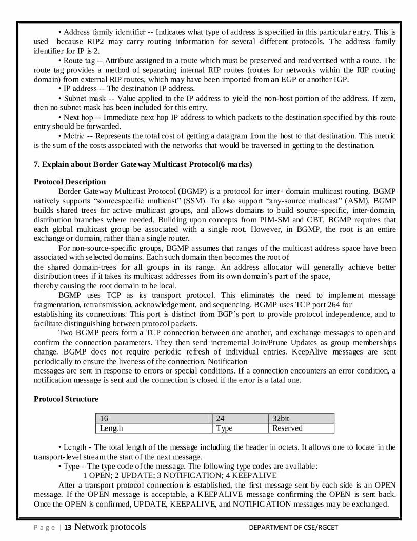
Protocol Structure
16 24 32bit
Length Type Reserved
• Length - The total length of the message including the header in octets. It allows one to locate in the
transport- level stream the start of the next message. • Type - The type code of the message. The following type codes are available:
1 OPEN; 2 UPDATE; 3 NOTIFICATION; 4 KEEPALIVE
After a transport protocol connection is established, the first message sent by each side is an OPEN message. If the OPEN message is acceptable, a KEEPALIVE message confirming the OPEN is sent back.
Once the OPEN is confirmed, UPDATE, KEEPALIVE, and NOTIFIC ATION messages may be exchanged.
P a g e | 14 Network protocols DEPARTMENT OF CSE/RGCET
The format of each message type is different.
8. Explain about Distance Vector Multicast Routing Protocol(11 marks)
Protocol Description
Distance Vector Multicast Routing Protocol (DVMRP) is an Internet routing protocol that provides an efficient mechanism for connectionless message multicast to a group of hosts across an internetwork.
DVMRP is an ―interior gateway protocol‖ (IGP); suitable for use within an autonomous system, but not between different autonomous systems. DVMRP is not currently developed for use in routing non-multicast
datagram’s, so a router that routes both multicast and unicast datagram’s must run two separate routing processes.
DVMRP is developed based upon RIP. DVMRP combines many of the features of RIP with the
Truncated Reverse Path Broadcasting (TRPB) algorithm. In addition, to allow experiments to traverse networks that do not support multicasting, a mechanism called tunneling was developed. The key differences
of DVMRP from RIP are: RIP routes and forwards datagram’s to a particular destination. The purpose of DVMRP is to keep track of the return paths to the source of multicast datagrams.
DVMRP packets are encapsulated in IP datagrams, with an IP protocol number of 2 (IGMP).
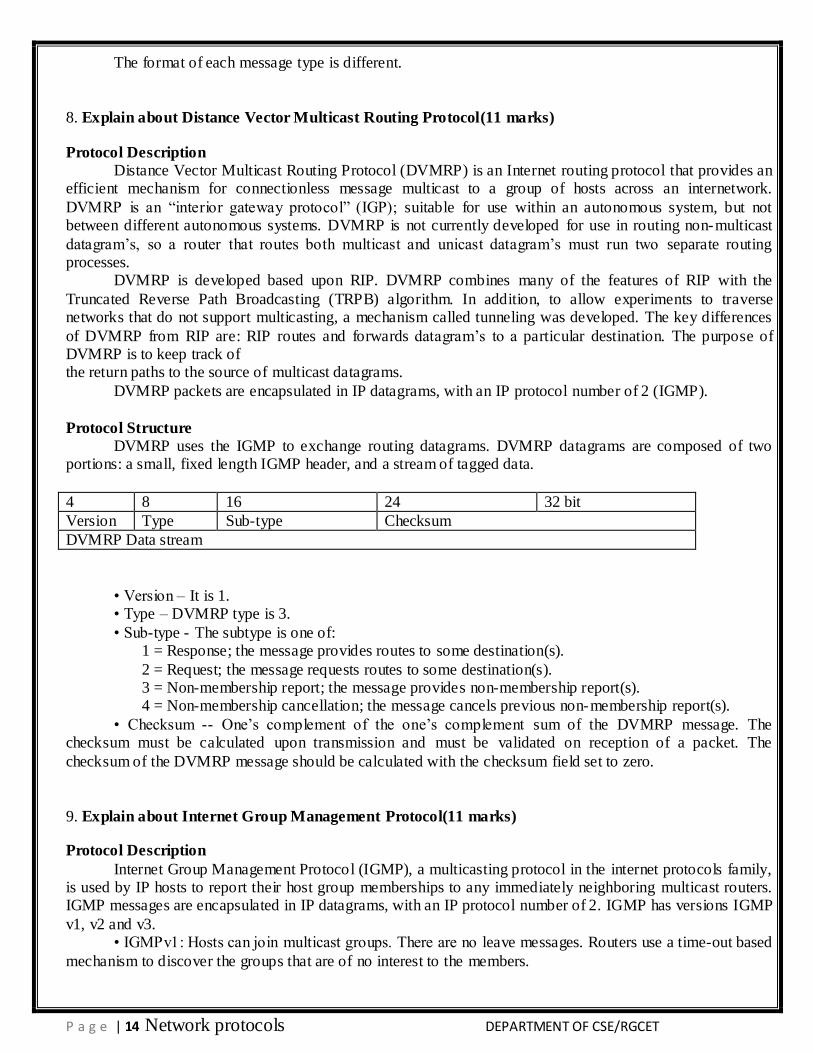
Protocol Structure
DVMRP uses the IGMP to exchange routing datagrams. DVMRP datagrams are composed of two portions: a small, fixed length IGMP header, and a stream of tagged data.
4 8 16 24 32 bit
Version Type Sub-type Checksum
DVMRP Data stream
• Version – It is 1. • Type – DVMRP type is 3.
• Sub-type - The subtype is one of: 1 = Response; the message provides routes to some destination(s).
2 = Request; the message requests routes to some destination(s). 3 = Non-membership report; the message provides non-membership report(s). 4 = Non-membership cancellation; the message cancels previous non-membership report(s).
• Checksum -- One’s complement of the one’s complement sum of the DVMRP message. The checksum must be calculated upon transmission and must be validated on reception of a packet. The
checksum of the DVMRP message should be calculated with the checksum field set to zero.
9. Explain about Internet Group Management Protocol(11 marks)
Protocol Description
Internet Group Management Protocol (IGMP), a multicasting protocol in the internet protocols family, is used by IP hosts to report their host group memberships to any immediately neighboring multicast routers. IGMP messages are encapsulated in IP datagrams, with an IP protocol number of 2. IGMP has versions IGMP
v1, v2 and v3. • IGMPv1: Hosts can join multicast groups. There are no leave messages. Routers use a time-out based
mechanism to discover the groups that are of no interest to the members.
P a g e | 15 Network protocols DEPARTMENT OF CSE/RGCET
• IGMPv2: Leave messages were added to the protocol, allowing group membership termination to be quickly reported to the routing protocol, which is important for high-bandwidth multicast groups and/or
subnets with highly volatile group membership. • IGMPv3: A major revision of the protocol allows hosts to specify the list of hosts from which they
want to receive traffic. Traffic from other hosts is blocked inside the network. It also allows hosts to block inside the network packets that come from sources that send unwanted traffic.
The variant protocols of IGMP are: • DVMRP: Distance Vector Multicast Routing Protocol.
• IGAP: IGMP for user Authentication Protocol. • RGMP: Router-port Group Management Protocol.
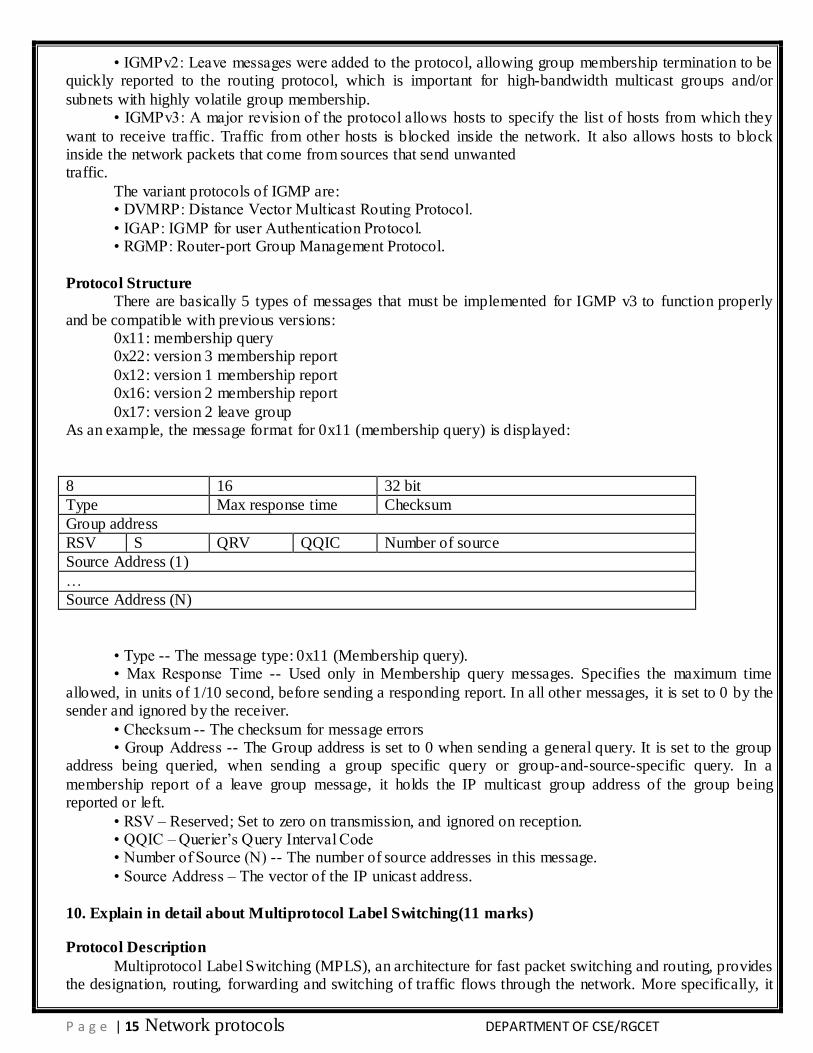
Protocol Structure
There are basically 5 types of messages that must be implemented for IGMP v3 to function properly
and be compatible with previous versions: 0x11: membership query 0x22: version 3 membership report
0x12: version 1 membership report 0x16: version 2 membership report
0x17: version 2 leave group As an example, the message format for 0x11 (membership query) is displayed:
8 16 32 bit
Type Max response time Checksum
Group address
RSV S QRV QQIC Number of source
Source Address (1)
…
Source Address (N)
• Type -- The message type: 0x11 (Membership query). • Max Response Time -- Used only in Membership query messages. Specifies the maximum time
allowed, in units of 1/10 second, before sending a responding report. In all other messages, it is set to 0 by the sender and ignored by the receiver.
• Checksum -- The checksum for message errors • Group Address -- The Group address is set to 0 when sending a general query. It is set to the group
address being queried, when sending a group specific query or group-and-source-specific query. In a
membership report of a leave group message, it holds the IP multicast group address of the group being reported or left.
• RSV – Reserved; Set to zero on transmission, and ignored on reception. • QQIC – Querier’s Query Interval Code • Number of Source (N) -- The number of source addresses in this message.
• Source Address – The vector of the IP unicast address.
10. Explain in detail about Multiprotocol Label Switching(11 marks)
Protocol Description
Multiprotocol Label Switching (MPLS), an architecture for fast packet switching and routing, provides the designation, routing, forwarding and switching of traffic flows through the network. More specifically, it
P a g e | 16 Network protocols DEPARTMENT OF CSE/RGCET
has mechanisms to manage traffic flows of various granularities. It is independent of the layer-2 and layer-3 protocols such as ATM and IP. It provides a means to map IP addresses to simple, fixed-length labels used by
different packet forwarding and packet-switching technologies. It interfaces to existing routing and switching protocols, such as IP, ATM, Frame Relay, Resource Reservation Protocol (RSVP) and Open Shortest Path
First (OSPF), etc. In MPLS, data transmission occurs on Label-Switched Paths (LSPs). LSPs are a sequence of labels at
each and every node along the path from the source to the destination. There are several label distribution
protocols used today, such as Label Distribution Protocol (LDP) or RSVP or piggybacking on routing protocols like border gateway protocol (BGP) and OSPF. Highspeed switching of data is possible because the
fixed- length labels are inserted at the very beginning of the packet or cell and can be used by hardware to switch packets quickly between links.
MPLS is designed to address network problems such as networks- speed, scalability, quality-of-service (QoS) management, and traffic engineering. MPLS has also become a solution to the bandwidth-
management and service requirements for next-generation IP-based backbone networks.
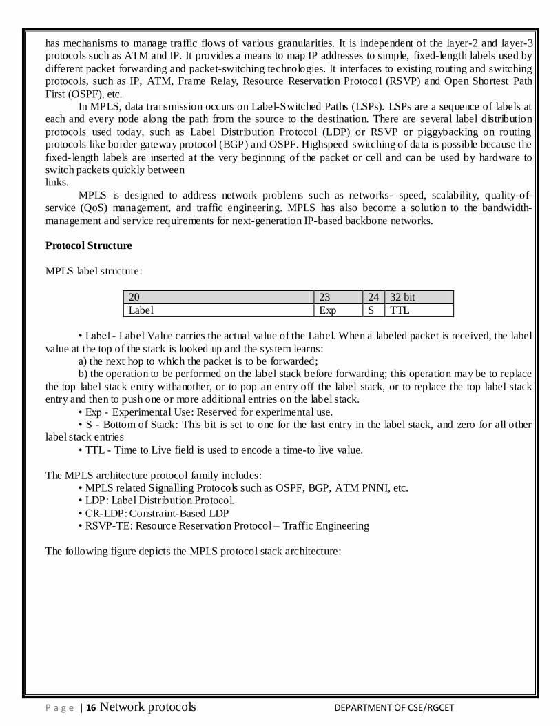
Protocol Structure
MPLS label structure:
20 23 24 32 bit
Label Exp S TTL
• Label - Label Value carries the actual value of the Label. When a labeled packet is received, the label
value at the top of the stack is looked up and the system learns: a) the next hop to which the packet is to be forwarded; b) the operation to be performed on the label stack before forwarding; this operation may be to replace
the top label stack entry withanother, or to pop an entry off the label stack, or to replace the top label stack entry and then to push one or more additional entries on the label stack.
• Exp - Experimental Use: Reserved for experimental use. • S - Bottom of Stack: This bit is set to one for the last entry in the label stack, and zero for all other
label stack entries
• TTL - Time to Live field is used to encode a time-to live value.
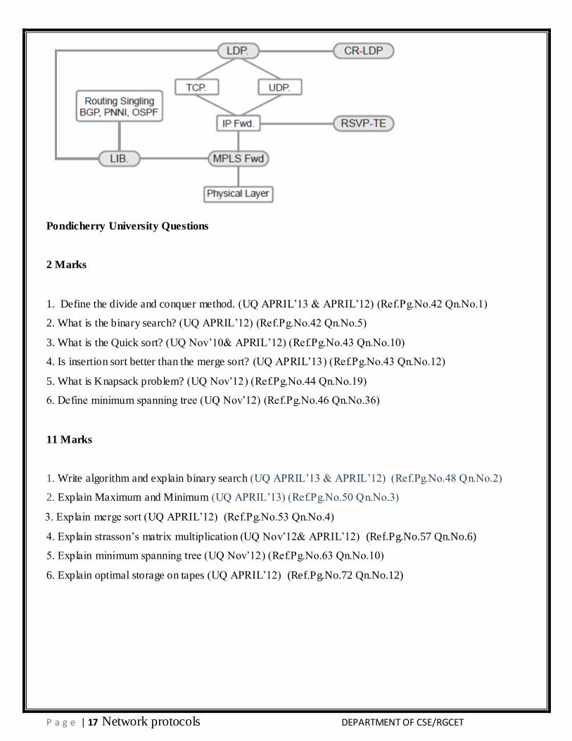
The MPLS architecture protocol family includes: • MPLS related Signalling Protocols such as OSPF, BGP, ATM PNNI, etc. • LDP: Label Distribution Protocol.
• CR-LDP: Constraint-Based LDP • RSVP-TE: Resource Reservation Protocol – Traffic Engineering
The following figure depicts the MPLS protocol stack architecture:
P a g e | 17 Network protocols DEPARTMENT OF CSE/RGCET
Pondicherry University Questions
2 Marks
1. Define the divide and conquer method. (UQ APRIL’13 & APRIL’12) (Ref.Pg.No.42 Qn.No.1)
2. What is the binary search? (UQ APRIL’12) (Ref.Pg.No.42 Qn.No.5)
3. What is the Quick sort? (UQ Nov’10& APRIL’12) (Ref.Pg.No.43 Qn.No.10)
4. Is insertion sort better than the merge sort? (UQ APRIL’13) (Ref.Pg.No.43 Qn.No.12)
5. What is Knapsack problem? (UQ Nov’12) (Ref.Pg.No.44 Qn.No.19)
6. Define minimum spanning tree (UQ Nov’12) (Ref.Pg.No.46 Qn.No.36)
11 Marks
1. Write algorithm and explain binary search (UQ APRIL’13 & APRIL’12) (Ref.Pg.No.48 Qn.No.2)
2. Explain Maximum and Minimum (UQ APRIL’13) (Ref.Pg.No.50 Qn.No.3)
3. Explain merge sort (UQ APRIL’12) (Ref.Pg.No.53 Qn.No.4)
4. Explain strasson’s matrix multiplication (UQ Nov’12& APRIL’12) (Ref.Pg.No.57 Qn.No.6)
5. Explain minimum spanning tree (UQ Nov’12) (Ref.Pg.No.63 Qn.No.10)
6. Explain optimal storage on tapes (UQ APRIL’12) (Ref.Pg.No.72 Qn.No.12)