Embed Size (px)
Citation preview

DEPARTMENT OF COMMERCEBUREAU OF STANDARDSGeorge K. Burgess, Director
TECHNOLOGIC PAPERS OF THE BUREAU OF STANDARDS, No. 252
[Part of Vol. 18]
THE NICK-BEND TEST FORWROUGHT IRON
BY
HENRY S. RAWDON, Physicist
SAMUEL EPSTEIN, Associate Physicist
Bureau of Standards
February 29, 1924
PRICE, 10 CENTS
$1.25 PER VOLUME ON SUBSCRIPTION
Sold only by the Superintendent of Documents, Government Printing Office
Washington, D. C.
WASHINGTONGOVERNMENT PRINTING OFFICE
1924


THE NICK-BEND TEST FOR WROUGHT IRON.
By Henry S. Rawdon and Samuel Epstein.
ABSTRACT.
The "nick-bend" test is included in nearly all specifications for wrought iron, the
character of the fracture of a nicked bar being the criterion by which the material is
judged. A coarsely crystalline fracture is generally considered as indicative of inferior
material. Most American specifications are very indefinite regarding the manner bywhich the specimen is to be broken and permit any method between slowly applied
pressure and a single-blow impact stress. This investigation was carried out uponeight different grades of wrought iron and one of open-hearth iron which were
fractured under different conditions and the character of the fracture studied. The" crystallinity " of the fracture depends upon the size and distribution of the slag
threads in the wrought iron and is a maximum in open-hearth iron, which contains no
such slag inclusions. The rate at which the specimen is fractured also affects the
character of the break, and when broken by severe impact crystallinity usually re-
sults. The same material broken by bending, which is permitted by most specifica-
tions, usually shows a fibrous fracture. The results show that the test can not be
depended upon to show the presence of "steel'
' in wrought iron nor to give results bywhich the phosphorous content may be judged. In short, in many specifications the
"nick-bend clause" is meaningless and should either be eliminated or redefined.
CONTENTS.Page
I . Introduction 1 16
II. Scope of investigation 117
III. Materials used 117
1. Chemical composition 119
2
.
Mechanical properties 12
1
3
.
Structure 123
IV. Testing procedure 125
1. Method of notching 126
2. Methods of fracturing 127
(a) Transverse bend 127
(6) Upright bend 128
(c) Upright bend, second method 129
(d) Impact, hammer blows 130
(e) Impact, single blow 130
3
.
Special tests 131
(a) Effect of size of specimen 131
(b) Preliminary cold working 132
(c) Impact tests of open-hearth iron 132
V. Results 134
VI. Discussion 141
VII. Recommendations 150VIII. Summary and conclusions „ 153
"5

1 1
6
Technologic Papers of the Bureau of Standards. [Vol. 18
I. INTRODUCTION.
In practically all specifications for wrought iron in the form of
rods and bars, and very often plates, the material is required to
pass satisfactorily a "nick-bend" test. The clause from the
standard specifications of the American Society for Testing
Materials * for stay bolt, engine bolts, and extra refined wrought-
iron bars may be quoted as typical of this requirement:
The test specimen when nicked 25 per cent around with a tool having a 6o° cutting
edge, to a depth of not less than 8 nor more than 16 per cent of the diameter of the speci-
men and broken, shall show a wholly fibrous fracture. Bend tests may be made bypressure or by blows.
In some grades of wrought iron a certain percentage of crystal-
line area is permitted in the fracture of a test specimen broken as
described above. For example, the standard specifications of the
A. S. T. M. for wrought-iron plates (specification A 42-18) permit
10 per cent crystalline area in a fractured nick-bend specimen of
wrought-iron plate. According to the Navy specifications 2 few
crystalline spots will be tolerated in the fracture of a nick-bend
specimen of wrought-iron bars for the manufacture of chain,
provided they do not exceed 10 per cent of the total area of the
face of the fractured specimen.
The requirements of British specifications for wrought iron maybe illustrated by the following clause from specification 51 of the
British Engineering Standards Association:
Test pieces * * * shall be lightly and evenly nicked on one side with a sharp
cutting tool and bent back at this point through an angle of 180 by pressure in a press
or by a succession of light blows, when they shall show a fibrous fracture free from slag
or dirt. The same test pieces when nicked all around and broken off short shall show
a fine uniform crystalline fracture.
The following clause 3 may be taken as representative of the
French method of carrying out this test:
The bars, notched by machine or by a chisel, are broken suddenly by a hand sledge
or by a power hammer while firmly held at one end. The iron ought never to show
in its texture large brilliant, or laminated crystalline areas; the grain should be semi-
fine, with slight tears; the fiber should be white, elongated, and without traces of slag.
It is quite evident from the preceding that the nick-bend test
for wrought iron is a common requirement; also that there are
pronounced differences to be noted in the manner in which this
test may be carried out. In none of the specifications for wrought
iron examined by the authors was there any definite suggestion
1 1921 Book of A. S. T . M. Standards, p. 317, specification A 84-21.
2 U. S. Navy specifications No. 47-I-ia.
3 Specifications techniques et cahiers des charges unifies; Chemins de fer Francais. Ch. Beranger, pub-
lisher, Paris.

IS£] The Nick-Bend Test for Wrought Iron. 117
offered as to the real significance of the crystalline areas in the
fractures of the nick-bend specimens.
It is generally admitted by testing engineers that considerable
experience is necessary in conducting this test and in interpreting
the results. This is evidenced by the requests which have been
received by this bureau for help in the interpretation of the results
obtained in this test. Figure 1 shows an assembled group of tested
specimens of wrought iron submitted and illustrates the general
type of results which may be expected in practice in carrying out
the test. It was principally for the purpose of obtaining reliable
information for replying to such inquiries that the investigation
discussed below was undertaken.
II. SCOPE OF INVESTIGATION.
In brief, the investigation consisted of the fracturing, under
known conditions, of nicked bars of a number of grades of wrought
iron, the composition, mechanical properties, and structure of
which had been carefully determined. The material, which wascontributed by various manufacturers for the purpose, in most
cases had been manufactured to meet certain A. S. T. M. speci-
fications. Nicked bars, representative of the different materials
furnished, were broken under different conditions varying from a
simple transverse bending of a specimen supported at the ends to
a severe single-blow impact test (drop test) . The appearance and
nature of the fracture produced under these different methods of
fracturing was, of course, the feature which received most attention.
The test is somewhat of the same general nature as the standard-
ized notch-bar impact test, so that it might be expected, a priori,
that any generalizations concerning the latter, such as the effect
of the character of the notch, ought to apply, to some degree at
least, in the discussion of this test.
III. MATERIALS USED.
The general nature and character of the different irons used in
the investigation are summarized in Table 1 , the source from which
each material was obtained being referred to by a letter. Theorder in which the materials have been arranged has no significance
other than that it represents the sequence in which they were
received at the Bureau of Standards from the manufacturers.
Most of the irons were in the form of i-inch diameter rods of
12-foot lengths. These were cut up into specimens 6 inches in

n8 Technologic Papers of the Bureau of Standards. [Vol 18
Fig. 1.
—
Typical fracture of wrought iron broken by the nick-bend test, submitted by a
commercial laboratory {slightly less than X-0- The notch in each case is at the left.
(a) i-inch bar nicked and broken by sledge blows.(b) Specimen similar to (a) broken by transverse bending, the specimen (notch downward) being sup-
ported at the ends and loaded above the notch. Note the "tension" and the "compression" crystalline
areas in both (a) and (6).
(c) Specimen similar to (a) fractured by lengthwise compression by means of light blows from a steamhammer. The fracture was largely fibrous.
(d) Fracture of a nicked bar produced by lengthwise compression in a testing machine.(e) Specimen similar to (d) broken by sledge blows. Note the absence of crystallinity on the tension
side and the very prominent crystalline area on the compression side of (d) and (e).
(/) Side view of a nicked specimen broken by lengthwise compression in the testing machine. Notethe "compression" crystalline area.
(g) Specimen broken by lengthwise compression in the testing machine.(h) Specimen broken by light sledge blows. Note the conspicuous "compression" crystalline area in each
case and the complete absence of crystallinity on the tension side of the bar.(i), (j) Two views, at different focus, of a nicked specimen broken as by sledge blows. Note both
"tension" and "compression" crystalline areas.
(k) Same specimen as (i), broken by lengthwise compression. Note the fibrous character of the fracture.

Ea
p™im] ^xe ^*ick-Bend Test for Wrought Iron. 119
length, each one being marked so as to record its location in the
bar. In the following tests duplicate specimens were used for the
most part, care always being taken that for such duplicates two
specimens adjacent to each other along the length of the bar were
chosen, so as to eliminate possible variations in properties along
the length of the bar.
TABLE 1.—Materials Used in Investigation.
Source.Designationof materials.
Nature of materials.
fAl . .
A A2. 1-inch diameter engine-bolt iron, grade C, A. S. T. M. specifications A 84-21.
[A3 1-inch diameter all-puddle bar, A. S. T. M. specifications A 41-18.
fBl 1-inch diameter stay-bolt iron, grade A, A. S. T. M. specifications A 84-21.
B JB2 1-inch diameter extra refined, grade C, A. S. T. M. specifications A 84-21.
B3 1-inch diameter refined iron, A. S. T. M. specifications A 41-18.
C C 1-inch diameter special grade, double-refined iron.
D D 1-inch diameter stay-bolt iron, grade A, A. S. T. M. specifications A 84-21.
E E •j^-inch bar, from first rough rolling of puddled bloom, squeezed from puddled
F .. - Fball (intermediate product).
1-inch diameter high-phosphorus wrought iron.
G G 2-inch diameter engine-bolt iron, grade B, A. S. T. M. specifications A 84-21.
H H "Open-hearth" iron.
For comparison with the regular commercial grades of wrought
iron several special irons were also included. Material E was
used to represent an intermediate stage in the manufacture of
wrought iron and should not be considered as representative of
the finished product of any manufacturer. It was included in the
series for the purpose of showing in some measure the extent to
which the properties of the finished product are influenced bythe amount of "refining
1
' received by the material.
Material F was a wrought iron of exceptionally high phosphorus
content. G, although a regular commercial product, was of a
much larger size than the other bars tested and was included for
the purpose of showing to what extent the crystallinity in a frac-
ture is dependent upon the size of the bar used. Material H des-
ignated as'
' open-hearth iron " is a commercial product which has
a structure very similar to wrought iron, except that the slag
threads which give the latter its "fibrous" appearance are en-
tirely lacking. In using this material it was hoped that the results
would show to what extent the absence of slag threads affect the
crystalline appearance of the fracture.
1. CHEMICAL COMPOSITION.
It is quite generally recognized that, for a material which lacks
homogeneity to the extent that wrought iron does, the chemical
composition is usually of relatively slight significance. How-

120 Technologic Papers of the Bureau of Standards. [Vol. 18
A: 5, 63
FlG. 2.
—
Typicalfractures of the various grades of iron broken in tension.
(a) Oblique (45°) view of the end of the broken tension specimen.(b) Side view of the specimens shown in (a)
(c) End view of fractured notched-tension specimens.Nocrystallinity is to be observed in the fractures of any of the specimens of wrought iron (A to G, inclusive).

RawdonlEpstein J
The Nick-Bend Test for Wrought Iron. 121
ever, for purpose of reference and comparison, there are given in
Table 2 the results of the chemical analyses of the materials used.
TABLE 2.—Composition of Materials Used. ]
Elements determined.
Specimen.
Carbon.Man-ganese.
Phos-phorus.
Sulphur. Silicon.
AlPer cent.
0.04.03.04.03
.01
.02
.03
.07
.04
.02
.03
.02
Percent.0.046.051.114.031
.030
.080
.028
.025
.031
.02
.07
.02
Percent.0.136.139.132.083
.126
.129
.114
.082
.103
.345
.150
.004
Per cent.0.025.022.027.015
.016
.017
.023
.015
.023
.026
.012
.020
Per cent.0.265
A2... .25A3 .09Bl . 13
B2 .16B3 .10C .17D .10
E .22F .22G .19H .003
Analysis by H. A. Bright, associate chemist, Bureau of Standards.
Fig. 3.
—
Typical fractures of wrought iron broken by the notched-bar impact (Izod) test.
Only a few of the specimens show any evidence of crystalline areas in the fracture. Note the high phos-phorus wrought iron, F, and the open hearth iron, H.
2. MECHANICAL PROPERTIES.
In Table 3 are summarized the results of the mechanical tests
upon the various materials. In addition to the usual tensile
properties, the behavior of the material under several other
methods of stress application was determined, the tests chosen
74563°—24 2

122 Technologic Papers of the Bureau of Standards. [Vol.iS
being those which, it was felt, might possibly throw some light
upon the reason for the character of the fracture resulting from the
nick-bend method of testing. The resistance to shock was deter-
mined by the single-blow notched-bar impact test, the Izod
machine being used for most of the determinations, since this
permits of several tests being made upon a single specimen; the
Eden-Foster method was employed for determining the behavior
under repeated impact. The special tension test given in Table
3 was carried out upon specimens in which the reduction of the
Fig. 4.
—
Typical fractures of iron broken by repeated impact {Eden-Foster test).
Note the traces of crystallinity in E, F, G, and H
bar to a diameter of 0.505 inch was made at only one point along
the length by means of a 6o° notch. The general character of
the results obtained in such a test are well known; there is no
appreciable elongation or reduction of area, and the ultimate
tensile strength is approximately that obtained in an ordinary
tension test if allowance is made for the reduced cross-sectional
area in calculating. The nature of the fracture resulting under
the conditions of stress employed is of most importance so far as the
present investigation is concerned.

Rawdcm~\Epstein J
The Nick-Bend Test for Wrought Iron.
TABLE 3.—Mechanical Properties of Materials Used.
123
Tensile properties.
Material.
Yieldpoint. 1
Ultimatetensile
strength.
Elonga-tion in
2 inches.
Lbs./in.251.750
Per cent.
30.5
50, 350 32.0
51, 750 30.5
49, 350 36.0
50, 100 35.0
48, 000 19.5
51,250 38.5
48, 500 40.5
46, 750 11.0
53, 350 29
50, 500 36
43, 250 51.5
Reduc-tion of
area.
Notched-bartension test.
Yieldpoint. 1
Ultimatetensile
strength.
Impact resistance(Izod), energyabsorbed. 2 3
Repeatedimpacttest,
numberof blows,5-poundhammer. 4
Al.
a:.
A3.
Bl.
B2.
B3.
c.D.
Lbs./in. 2
36, 500
31, 750
36, 500
33, 600
37, 000
34, 500
37, 900
33, 750
28, 500
34, 250
32, 000
27, 000
Per cent.41.0
37.0
32.5
Lbs./in. 2 Lbs./in. 2
57,000
50.0 50,500
51.0
26.5 50,000
55. 55, 500
57. 54, 500
59, 000
58, 500
Ft. -lb.
35.5, 51.3, 38.5
48, 41, 46.
5
37.5, 47.5, 42.5
21,9123. 422
56, 000
60,500 55,
65,000 56.5
46, 49. 5,
44.5, 43.5,
45.5, 45.5,
61.
63.
47
45
62
45.5
44.5
15.035, 500
36, 000
29.5 47,000
39. 5 46, 000
76.5t
47,500
40, 500
42, 000
56, 000
58, 500
81,500
40, 30, 34
31.5, 25.5, 35
26,
29.
58.
47,24.
3.0221, 6307,070
10, 340
702700
1,9801.468
660306532
1,468726
1,952
3,1902,5902,486
1 From stress graph: Amsler testing machine was used with the usual 0.505-inch tension test specimens.2 Triple-notched specimens (1 cm 2 (0.394 by 0.394 inch) cross section, 45 ° V notch 0.079 inch deep) were
used, the notches being arranged on three sides of the specimen. Hence, the relationship of notch to orien-tation of slag threads varied in each specimen. The capacity of the Izod pendulum machine was 120 foot-
pounds.3 None of the specimens of wrought iron fractured completely upon impact. The results in each hori-
zontal line (F, G, H) were obtained with specimens from the same bar.4 Eden-Foster machine was used, the specimens being 63^ inches long, } •> inch in diameter, with a round
filleted notch 0.05 inch deep.5 2 1^-ineh drop; 4-inch drop was used for all the others.6 See also Table 4-
Some of the variations in the impact-resistance properties to
be noted for the same specimens of wrought iron in Table 3 are
undoubtedly to be attributed to variations in the location of the
notch on the specimen with respect to the arrangement of the
slag threads within. The variations in the impact resistance of
the open-hearth iron are discussed later at greater length.
3. STRUCTURE.
Macrographs showing the gross structure of the different grades
of iron are given in Figures 5 to 16, inclusive. In all cases the
finely ground section was etched with an aqueous solution of
ammonium persulphate. Concentrated hydrochloric acid wasalso used, but, on the whole, its use was not so convenient nor
successful as the ammonium persulphate. This reagent may be
considered as a weak acid, the action of which is intensified byoxygen. 4 The method of "piling" is plainly shown in the trans-
4 Use of ammonium persulphate for revealing the macrostructure of iron and steel. H. S. Rawdon, B. S.
Sci. Papers No. 402; 1920.

I24 Technologic Papers of the Bureau of Standards. [Vol. 18
verse sections. The conspicuous white streaks may be considered
in most cases as the steel-bearing portions of the iron. The posi-
^
Fig. 5.
—
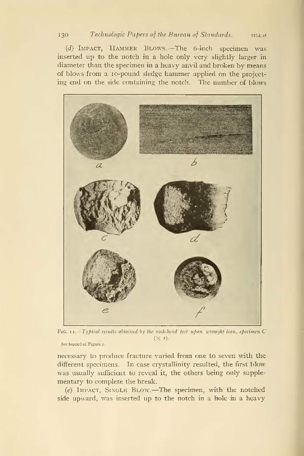
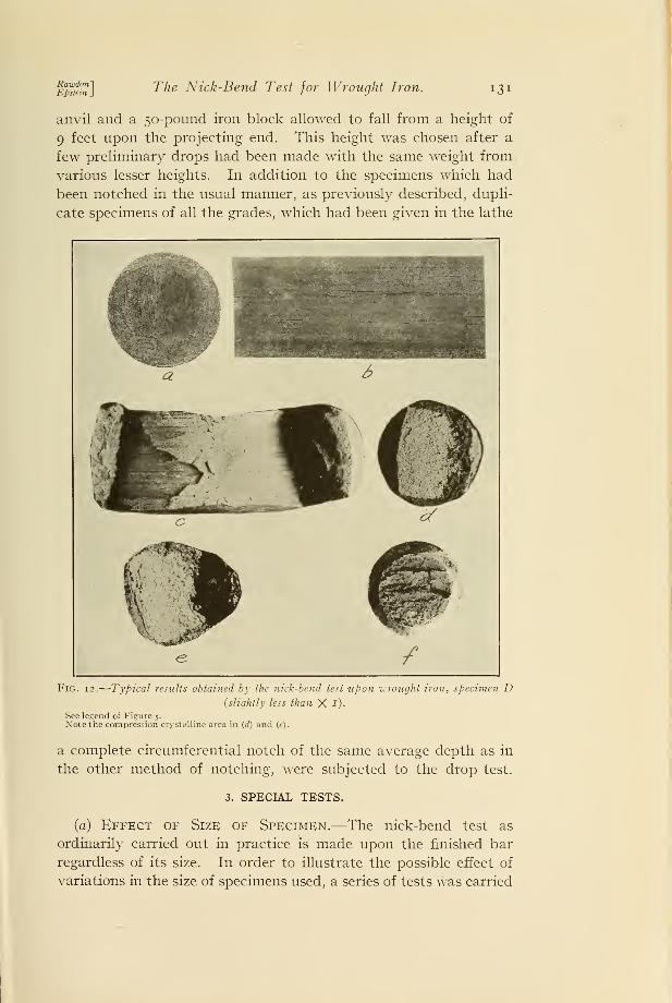
Typical results obtained by the nick-bend test upon wrought iron, specimen
A 1 (X 1).
(a) Transverse section, etched with ammonium persulphate to reveal the macrostructure.(b) Longitudinal section, etched with ammonium persulphate.(c) Fracture produced in the nicked bar by transverse bending, the load being applied opposite the
notch and the specimen supported 2 inches each side of the notch.(d) Fracture of a nicked bar broken by blows from a 10-pound sledge.(e) Fracture of a bar nicked on one side and broken by the drop test (50-pound, 9 feet).
(/) Fracture of a specimen with a circumferential notch broken as in (c).
The notched side of the bar is toward the left, in (/) the blow was received from the left.
tion of the notch with respect to the macrostructure can be easily
determined, since the notch is in the same relative position in all
the specimens as is shown in the different figures.

RawdonlEpstein J
The Nick-Bend Test for Wrought Iron.
IV. TESTING PROCEDURE.
125
The necessity for uniformity in the notching of the specimens
was recognized at the outset. The extensive investigations which
have been carried out on the interpretation of the notched-bar
Fig. 6.
—
Typical results obtained by the nick-bend test upon wrought iron, specimen A 2
(XI).See legend of Figure 5.
impact test have demonstrated beyond question the fact that the
results to be obtained are dependent upon the character of the
notch. Thus, of two bars of the same material notched to the
same depth, one with a sharp V notch the other having a notch
semicircular in section, the impact resistance of the first will, in
general, be much less than the second.

126 Technologic Papers of the Bureau of Standards. [Vol is
1. METHOD OF NOTCHING.
For nicking the bars before fracturing a special tool was em-ployed. This was a chisel, ground so as to produce a 6o° cut
and having a curved edge, the curve being somewhat greater
than that of the circumference of the rod which was to be nicked.
Fig. 7.
—
Typical results obtained by the nick-bend test upon wrought iron, specimen A 3(XI).
See legend of Figure 5.
Note the "compression" crystalline area in (d) and (e).
In order to secure uniformity, the nicks were all made by com-
pression in the testing machine, a load of 20,000 pounds being
applied upon the head of the chisel for two minutes. The depth
of the notch produced varied slightly with the different grades of
iron, from 0.129 "to 0.153 inch, the average depth being 0.14 inch.
Precautions were also taken to notch all the specimens from each

Rau'donlEpstein J
The Nick-Bend Test for Wrought Iron. 127
of the bars of wrought iron on the same side, so that the location
of the notch with respect to the arrangement of slag threads within
would be approximately the same throughout the series.
Fig. 8.
—
Typical results obtained by the nick-bend test upon wrought iron, specimen B 1
(XI).
See legend of Figure 5.
2. METHODS OF FRACTURING.
The following methods were used for fracturing the bars after
notching, as described above:
(a) Transverse Bend.—The 6-inch specimen, symmetrically
supported on a 4-inch span, was fractured in the Amsler testing
machine by having a cylindrical-nosed "pin" approximately 0.8

12! Technologic Papers of the Bureau of Standards. [Yo!. iS
inch (2 cm) thick forced into it until fracture occurred or the bentspecimen could be forced completely through the space betweenthe supports (4 inches)
.
(6) Upright Bend.—The notched 6-inch specimen after having
been given a slight preliminary bend was supported on end between
Fig. 9.
—
Typical results obtained by the nick-bend test upon wrought iron, specimen B 2
(XI).See legend of Figure 5.
the jaws of the Amsler testing machine and slowly compressed
lengthwise until fracture occurred, approximately three minutes
being required in the operation. A few of the specimens were also
given the preliminary bend before being notched. However, no
significant differences in the fractures resulting upon lengthwise

Raivdon 1
Epstein JThe Nick-Bend Test for Wrought Iron. 129
compression could be detected in such specimens as compared with
those which were notched before being given the preliminary
bend.
(c) Upright Bend, Second Method.—The test was carried out
as above, except that the forging press was used for applying
Fig. 10.
—
Typical results obtained by the nick-bend test upon -wrought iron, specimen B 3
(Xi).See legend of Figure 5.
the load, two applications of the load being necessary. The
slightly bent specimen was adjusted between the jaws of the press
and then suddenly compressed, less than one second being required
for the compression. It was necessary to readjust the partially
fractured specimen for the second compression.
74563°—24 3
130 Technologic Papers of the Bureau of Standards. [Vol. 18
(d) Impact, Hammer Blows.—The 6-inch specimen wasinserted up to the notch in a hole only very slightly larger in
diameter than the specimen in a heavy anvil and broken by meansof blows from a io-pound sledge hammer applied on the project-
ing end on the side containing the notch. The number of blows
Fig. ii.—Typical results obtained by the nick-bend test upon wrought iron, specimen C(Xi).
See legend of Figure s-
necessary to produce fracture varied from one to seven with the
different specimens. In case crystallinity resulted, the first blow
was usually sufficient to reveal it, the others being only supple-
mentary to complete the break.
(e) Impact, Single Blow.—The specimen, with the notched
side upward, was inserted up to the notch in a hole in a heavy
nTsfem] The Nick-Bend Test for Wrought Iron. 131
anvil and a 50-pound iron block allowed to fall from a height of
9 feet upon the projecting end. This height was chosen after a
few preliminary drops had been made with the same weight from
various lesser heights. In addition to the specimens which had
been notched in the usual manner, as previously described, dupli-
cate specimens of all the grades, which had been given in the lathe
Fig. 12.
—
Typical results obtained by the nick-bend test upon wrought iron, specimen D{slightly less than X i)-
See legend of figure 5.
Note the compression crystalline area in (d) and (e)
.
a complete circumferential notch of the same average depth as in
the other method of notching, were subjected to the drop test.
3. SPECIAL TESTS.
(a) Effect of Size of Specimen.—The nick-bend test as
ordinarily carried out in practice is made upon the finished bar
regardless of its size. In order to illustrate the possible effect of
variations in the size of specimens used, a series of tests was carried

132 Technologic Papers of the Bureau of Standards. [Vol. 18
out upon a wrought-iron bar 2 inches in diameter. The bar wascut into sections of a length convenient for testing, approximately
9 inches. The series was divided into two groups, alternate
specimens—that is, relative to their position in the initial bar
—
being placed in the same group. The bars constituting one group
were tested in the full size after notching
;
5 the others were reduced
in cross section to 1 inch diameter (fig. 15) and then tested in the
same manner. Care was taken so that for each particular methodof fracturing the specimens used were taken from adjacent por-
tions of the bar.
(b) Preliminary Cold Working.—The suggestion was madeby one of the manufacturers supplying material that the results of
a test may be influenced to a very marked degree by any cold
working the bar may receive prior to test. In order to try this
out, specimens 18 inches long cut from bars A 1
, A3, C, and D were
permanently stretched in the testing machine in amounts vary-
ing from 8 to 25 per cent, as measured on the central 2-inch
length of the stretch bar. Six-inch specimens were then cut from
the central portion of the bars and after nicking were fractured
by transverse bending and by the single-blow drop test.
(c) Impact Tests of Open-Hearth Iron.—It was evident
from the outset that the nick-bend test partakes more or less of
the nature of an impact test, according to the manner in which
it is carried out. In order to show the extent to which the results
of impact tests, particularly the character of the fracture, are
dependent upon the structural condition of the material tested, a
series of standard notched-bar impact tests was carried out in
addition to those reported in Table 3. For these open-hearth
iron was the material used, since this material closely resembles in
structure the ferrite or metallic matrix of wrought iron. The results
already obtained in the impact tests of wrought iron indicated,
in a measure, the important role of the slag threads of wrought
iron in influencing the type of fracture obtained and suggested
the desirability of a material free from such features as this for
this test. The preliminary heat treatment given the material to
produce variations in grain structure, together with the results
obtained, are summarized in Table 4. Microscopic examinations
of the fractured specimen were made, special attention being given
to the relation of the ''path" of the fracture and the crystalline
structure of the bar. Examinations were also made of crystalline
5 See footnote i, p. 116.

Rawdon'Epstein,
The Nick-Bend Test for Wrought Iron. 133
fractures obtained by other methods of fracturing, such as the
notched-bar tension test and repeated impact, and the results
compared with those obtained by simple impact.
Fig. 13.
—
Typical results obtained by the nick-bend test upon wrought iron, specimen E(Xi).
(a) Cross section of a bar etched with arnmonium persulphate to reveal the macrostructure.(b) Longitudinal section of a bar etched as in (a)
.
(c) Fracture produced by a transverse bend of a notched bar, the load being applied opposite the notchand the specimen supported 2 inches each side of the notch.
(d) Fracture of a nicked bar produced by a 10-pound sledge hammer. Note the small isolated crystalline
spots.(e) Fracture produced by the drop test (so-pound, 9 feet) on a specimen nicked on the "edge" of the
plate. Note the crystalline area on the tension side.
O') Fracture of a bar similar to (e) which was notched on the flat side of the plate. Xote the almostcomplete absence of crystallinity.
(/) Fracture of a bar similar to (e) , notched completely around. Xote the absence of crystalline areas.
(/') Fracture of a bar similar to (/) , the blow was so as to bend the specimen as in (e')
.

134 Technologic Papers of the Bureau of Standards. [Vol 18
V. RESULTS.
One of the principal difficulties in an investigation of the kind
discussed here lies in the effective presentation of the results, since
most of these can not be expressed numerically. A simple state-
Fig. 14.
—
Typical results obtained by the nick-bend test upon wrought iron of high-
phosphorus content, specimen F (X I)-
See legend of Figure 5.
ment with reference to the presence or absence of crystalline areas
in the fracture of the tested specimen would fall far short of ful-
filling the purpose of the investigation. To reproduce photo-
graphs of all the bars tested is also undesirable.
The characteristic features of the fractures produced by breaking
nicked specimens of the various grades of iron under different con-

E™tibt] The Nick-Bend Test for Wrought Iron. 135
ditions have been summarized by means of representative photo-
graphs in Figures 5 to 15, inclusive. For purposes of comparison
Figures 2,3, and 4, showing the fracture of the different materials
when subjected to the various mechanical tests; tension, impact,
and repeated impact, have been included. In none of the ordinary
tension or the notched-bar tension specimens (fig. 2) was there
any indication of a crystalline structure revealed in the fracture
of the wrought irons. In the notched-bar impact (Izod) fracture
only slight indications of crystallinity were shown by a few of the
specimens (fig. 3) . Of those fractured by repeated impact (Eden-
Foster test) only one gave any indication of crystalline spots
in the fracture. It may be concluded, then, that the nick-bend
test, as employed for the testing of wrought iron, is evidently
intended to reveal certain characteristics of the material which the
usual mechanical tests indicate only very slightly, if at all.
It will be seen from Figures 2,3, and 4 that the behavior of open-
hearth iron (specimen H) when tested was quite different from that
of the wrought irons. Although very ductile, as was evidenced bythe usual tension test, this material showed a very pronounced
crystalline fracture when broken by the notched-bar tension tests.
Likewise, the notched-bar impact specimens showed much more
evidence of a crystalline fracture than did the similar specimens of
wrought iron. This feature is discussed below at greater length.
The fractures produced in nicked bars by lengthwise com-
pression in the testing machine and in the forging press were found
for most of the materials not to differ in any marked respects from
those resulting from simple transverse bending. Hence, in order
to conserve space in reproduction, photographs respresentative of
this method of fracturing have not been included in the sets given.
The photographs were taken so as to show all the specimens at
natural size. In many cases, however, it was necessary to tilt the
sample so as to reveal clearly the characteristic features; hence
some distortion appears in some of the photographs. It will be
evident even from a cursory examination of the fractures that
simple transverse bending of a nicked bar of each of the nine
grades of iron used was not sufficient to reveal in the fracture any
significant features, such as the nick-bend test is intended to show.
The fact that impact is necessary in the production of the large
conspicuous crystalline areas is evident in nearly all the figures
in the fractures resulting from the use of the sledge or from the
single-blow impact test. In many of the fractured specimens, and
particularly in the open-hearth iron, two crystalline areas may be

136 Technologic Papers of the Bureau of Standards. [Voi.18
noted, one immediately beneath the notch and the other on the
opposite side of the bar. This feature is illustrated in Figures 1,
Fig. 15.
—
Typical results obtained by the nick-bend test upon wrought iron, specimen G(Xi).
The small bars were obtained by machining the 2-inch bars to 1 inch diameter as indicated in (b).
(a) Longitudinal section, etched with amonium persulphate to reveal the macrostructure.(b) Transverse section etched in a similar manner.(c) Fracture produced in the nicked 2-inch bar by transverse bending, the load being applied centrally
on a 6-inch span, opposite the notch.(c') Fracture produced in the nicked i-inch bar stressed as in (c), 4-inch span.
6, 7, 12, 14, and 16, and the real significance of these two crystalline
areas will be considered later.

RawdonlEpstein J
The Nick-Bend Test for Wrought Iron. 137
Fig. 15 (Continued).
—
Typical results obtained by the nick-bend test upon wrought iron,
specimen G (X 1).
(d) Fracture produced in the nicked 2-inch bar by upright bend in the forging press.
(d') Fracture produced in the nicked i-inch bar, stressed as in (d.)
(e) Fracture produced in the nicked 2-inch bar by blows from a 10-pound sledge.
(e') Fracture produced in the nicked i-inch bar, stressed as in (<?).

138 Technologic Papers of the Bureau of Standards. [Vol. 18
Fig. 16.
—
Typical results obtained by the nick-bend test upon open-hearth iron, specimen
H. Notch is toward the left. (X i).
(a) Transverse section etched with ammonium persulphate.(b) Longitudinal section similarly etched.
(c) Fracture of a nicked broken by transverse bending, the load being applied centrally opposite the
nick, 4-inch span.(d) Fracture resulting from blows with a io-pound sledge.
.
(e), (c') , and (e") , fracture resulting from the drop test, 50-pound tup, 6, 4. and 3 feet, respectively.
(/) and (/') , fracture resulting from the drop test (50-pound, 9 feet) on circumferentially notched speci-
mens, notch one-eighth and one-sixteenth inch, respectively.
(<7) Results of an "upright bend" as carried outin the testing machine.
(h) Fracture resultingfrom an "upright bend" in the forging press. Note the two types oi crystalline
areas.

Rawdon'Epstein _
The Nick-Bend Test for Wrought Iron. 139
It will also be seen in the bars fractured by the single-blow
impact test that the extent of the notch around the specimen had
a pronounced effect upon the character of the fracture. In none
of the specimens of wrought iron having the circumferential notch
was there any pronounced crystallinity in the fracture when
Fig. 17.
—
Fractures resulting from the nick-bend test of wrought iron {grade C),
previously deformed by stretching (X J).
(a) The nicked specimen was broken by transverse bending.(b) Similar specimen broken by the drop test (50-pound, 9 feet)
.
(c) Similar specimen broken by the drop test (50-pound, 13 leet )
.
Compare with Figure 10.
broken by the drop test. Figure 15 shows the fractures which
were obtained with specimens of different cross-sectional area cut
from the same bar. It will be noted that areas which were crys-
talline in the smaller bars were not so in the fractures of the larger
ones.
The appearance of the fracture of the bars subjected to cold
working by stretching prior to carrying out the nick-bend test
140 Technologic Papers of the Bureau of Standards. [Vol. 18
showed no differences which might be considered as character-
istic of irons which had received such a treatment. The results
shown in Figure 17 for material C are typical of the fracturesobtained for all those tested. The cold working which the barreceived in the preliminary stretching increased the tensile strength
to a very marked extent, so that a much severer blow was neces-
sary in order to fracture the bar. For specimen C a fall of 13 feet
for the 50-pound weight was necessary in order to fracture the
specimen, whereas for the unstretched specimen a blow from the
same weight from 9 feet was sufficient. Aside from this no other
differences were noted and the characteristic features of the
fracture were not essentially changed. 6
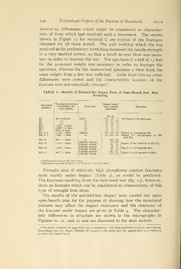
TABLE 4.—Results of Notched-Bar Impact Tests of Open-Hearth Iron AfterAnnealing.
Specimennumber.
Treatment, degreesCentigrade, fur-
nace cooled.Test used.
Impact resist-
ance, energyabsorbed.
Remarks.
HI As receiveddo
Izod »
Ft.-lb.L 66, 24, 629, 49, 69
See Figure 3 for fractures.H2 doH3 . ..do.... do 65, 66, 71
H13 1,100°, > 2 hour do.... 41, 46, 75
72, 75, 77
73, 78, 76194, 194, 195
23, 189, 199
199, 204
Figure 22, micrograph He.Figure 21, micrographs of
and He.
H14 1,000°, ]/2 hour900°, y2 hour
doH17 .. doHa, b, c 1,150°, 1 hour
1,000°, 1 hourCharpy
Hd, e, f . do Hd
H9, 10 900°, '
i hour. do
H21-24
H25-28
H29-32
1,150°, 1 hour
1,000°, 1 hour
900°, y2 hour
f Charpy, square(Charpy, round -
. .
.
( Charpy, square\Charpy, round/Charpy, square\Charpy, round
15, 18034, 34
10, 14
27, 24181, 171
177, 173
| Figure 19 for fractures of mi-
Figure 22, micrograph H21.
[Figure 19, micrographs of H30.
32.
1 Triple-notch bars in all Izod tests.2 Specimen 0.45 inch diameter, 45° V notch, 0.13 inch deep.
Wrought iron of relatively high phosphorus content fractures
more readily under impact (Table 3), as would be predicted.
The fractures resulting from the nick-bend test (fig. 14), however,
show no features which can be considered as characteristic of this
type of wrought iron alone.
The results of the notched-bar impact tests carried out uponopen-hearth iron for the purpose of showing how the structural
features may affect the impact resistance and the character of
the fracture under impact are given in Table 4. The character-
istic differences in structure are shown in the micrographs in
Figures 20, 21, and 22 and are discussed in the next section.
6 The results obtained are apparently not in accordance with those published by Jones and Greaves,
Proceedings, Inst. Civ. Engrs. (British) 211 (1920-21), who report that the general effect of overstrain is
to reduce the impact figure

ISSrin]The Nick-Bend Test for Wrought Iron. 141
VI. DISCUSSION.
It is evident from the results summarized above that the rate
at which the load is applied in fracturing the notched bars of
wrought iron is of very great importance and appears to be one of
the predominating factors which determine the character of the
fracture. Each of the nine grades of wrought iron, when stressed
slowly or at a moderate rate in compliance with A. S. T. M. speci-
fications for such materials, broke without showing any marked
tendency toward crystallinity ; whereas when fractured by impact,
either by sledge blows or by the drop test, the appearance of the
fracture was very materially changed. All of the specimens
showed crystalline areas the size of which varied with the different
grades of iron.
Another factor which appears to bear a close relationship to the
size of the crystalline areas developed under impact is the relative
size and distribution of the slag threads. Irons C and D (figs. 1
1
and 12) may be used to illustrate this point. The appearance of
these two materials when etched showed a very uniform distribu-
tion of the slag threads, as compared with some of the other speci-
mens, and also indicated the absence of any exceptionally large
slag threads. The iron matrix was very uniform in appearance and
lacked the conspicuous contrasting streaks which were so promi-
nent in some of the other irons. Material D showed the most uni-
form structure by far of the nine grades of iron tested and also de-
veloped the most conspicuous crystalline fractures in the nick-bend
test. Material C, which was somewhat less uniform in appearance,
showed somewhat smaller crystalline areas when fractured.
When the continuity of the metallic matrix is broken by large
slag threads, the probability of a fibrous fracture being produced is
increased proportionally. In case there are very prominent slag
plates favorably oriented with respect to the direction of the ap-
plied stress, longitudinal separation of the metal following the
fracturing of a small portion of the metal may result as illustrated
by several of the specimens tested. This is much more apt to occur
when the specimen is slowly stressed than when subjected to shock.
The behavior of material E, which was wrought iron which hadintentionally not received complete refining, confirms what has just
been said concerning the influence of prominent slag threads on the
production of crystalline fractures under the nick-bend test. This
material represented an intermediate stage in the manufacture of
wrought-iron plate and contained rather conspicuous plates of slag

142 Technologic Papers of the Bureau of Standards. \Voi is
alternating with layers of iron, the whole being arranged like the
leaves in a book. When nicked and fractured on the edge of the
"leaves," conspicuous crystalline areas resulted; whereas whenbroken under the same conditions, except that the nick was made at
right angles to the first—that is, on the flat side of the leaves—no
crystallinity resulted. It should be noted, however, that the'
' depth'
' of the cross section of the specimen was not the same in
both cases, a fact which may have had some effect upon the be-
havior of the sample.
The pronounced crystallinity of the fracture of the open-hearth
iron (material H) when broken by the nick-bend test is very strik-
ing. As is shown in Figure 16, this material even when slowly
stressed by transverse bending gave a fracture as crystalline in ap-
pearance as that resulting from impact in the drop test. The ab-
sence of slag threads from this material by which the continuity of
the metallic matrix would be broken, without question will ac-
count in large measure for this characteristic behavior. Any sep-
aration once started would be propagated relatively easily across
the specimen instead of being forced to start anew repeatedly, as
would be the case with wrought iron where the continuity of the
metallic matrix is interrupted by numerous included slag threads.
By many, in practice, the nick-bend test is thought to reveal
the presence of steel in wrought iron. That this is not so was
readily shown by an examination of the microstructure of the
specimen in the portions showing the crystalline fracture. The
fact that prominent "steel" streaks, as revealed by the deep
etching of the specimens, were not found in all of the irons, whereas
all of them readily developed "crystallinity" when the nicked
specimen was broken in the proper manner, should constitute
sufficient evidence in deciding upon this point. However, one
of the specimens, A 3 (fig. 7) ,gave results which suggest that the
presence of prominent steel streaks within wrought iron do affect
to some extent the character of the break. The three prominent
areas (fig: 7) seen in the cross section of specimen A3 were found
to have the characteristic microstructure of low-carbon steel.
In nearly all the fractures of this bar three areas corresponding
to these streaks were noted, and in the fractures resulting from
impact stresses these areas were largely crystalline in appearance.
Likewise, it may be noted in B 1 (fig. 8) that the location and shape
of the crystalline areas resulting from impact, particularly bythe sledge, appear to have been determined to a noticeable extent
by the white (steel bearing) streaks to be seen in the cross section

RawdonlEpstein J
The Nick-Bend Test for Wrought Iron. *43
-f *
<
,. .*. •• «
\
Mr
m ' J'.H
w " f
«,
s ^
ui •Co
I °^" h J:
o a g.<u
tic |-5"H
« £~ m 3
S b o C i»
« <ub-a 2
T5 w 9 at
1§g* 3 * 2« M tf, Q o
O 1» t- 4» .
^ &>• 2
•C o-=. o
&£ <u S^
a « ~~ ..
o.5'£ wotea s >>
«
_3 a o.y
a >,;"? o
•* c« £"3
J2 4J O 4; CU
j!, 4J D a; 10
a to tn to Si5 2 ° °o 3 3 5 "

144 Technologic Papers of the Bureau of Standards. [Vol. iS
of this bar. This factor, as contributory to the character of the
fracture, is of only minor importance, however, as compared to
the character and distribution of the stress causing rupture.
In short, it may be concluded that the crystalline areas in the
fractures of wrought-iron bars broken by the nick-bend test are
not to be interpreted, necessarily, as indicative of the presence
of steel. On the other hand, steel streaks do appear to render
wrought iron somewhat more prone to develop crystalline frac-
tures than similar irons free from such streaks.
Mention has already been made of the presence of two crystal-
line areas of different types in many of the nick-bend fractures,
one on the tension side of the stressed specimen and the other
near the compression side. Although the two types may appear
very similar in a photograph, to the eye there are very distinct
and characteristic differences to be noted. The "compression"
areas, although crystalline in appearance, lack the rough, sharp
contour, and hence much of the sparkling appearance of the
"tension" areas. The softer sheen of the compression areas,
taken in connection with the fact that they are best seen whenviewed at certain definite angles, suggested an appearance char-
acteristic of a surface covered with flattened scales.
The fact that the location of the notch along the circumference
of the bar, which thus fixes the direction from which the stress
will be applied, determines the position of these two areas is very
significant. It would appear that since the relative position of the
two areas can be varied at will, they do not depend upon nor
indicate different characteristic properties of the material.
The real difference between these two types of crystalline areas is
best shown by an examination of the microstructure as illustrated
in Figure 18, which represents longitudinal sections of a specimen
of open-hearth iron perpendicular to the face of the fracture. It
will be noted that in the tension crystalline areas the fracture oc-
curred as a transcrystalline break; that is, along cleavage planes,
without any deformation of the individual crystals. The direc-
tion of the cleavage of several adjacent crystals was found to coin-
cide frequently, thus giving rise to larger ''facets." The contour
of the surface resulting from this type of rupture presents a rough,
jagged outline along any right section taken through it. These
features in the fracture of a ductile metal as determined by ordin-
ary tests are generally considered characteristic of a break occur-
ring very suddenly, usually, though not always, by impact. In
Rawdon'Epstein .
The Nick-Bend Test for Wrought Iron. 145
the fibrous portion of the fracture, for example between the two
crystalline areas, the crystals of iron were severely deformed by
tension, each being drawn out to a fine point at the place of rup-
ture. Evidently the stress causing rupture, in this part of the bar
acted at a much slower rate than in the portion which gave the
crystalline break just described. The appearance of the metal in
the compression crystalline areas shows that the grains were sub-
jected to very severe compression previous to the final tensile
break. Many of the grains were flattened perpendicularly to the
length of the bar, and others not so severely distorted in shape
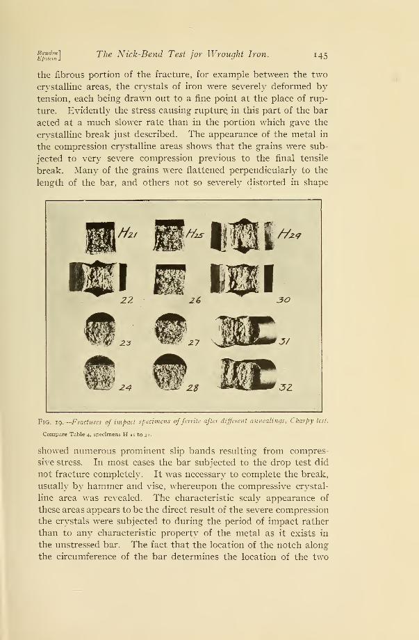
Fig. 19.
—
Fractures of impact specimens offerrite after different annealings, Charpy test.
Compare Table 4, specimens H 21 to 32.
showed numerous prominent slip bands resulting from compres-
sive stress. In most cases the bar subjected to the drop test did
not fracture completely. It was necessary to complete the break,
usually by hammer and vise, whereupon the compressive crystal-
line area was revealed. The characteristic scaly appearance of
these areas appears to be the direct result of the severe compression
the crystals were subjected to during the period of impact rather
than to any characteristic property of the metal as it exists in
the unstressed bar. The fact that the location of the notch along
the circumference of the bar determines the location of the two

146 Technologic Papers of the Bureau of Standards. [Vol. 18
types of crystalline areas is also very significant. It is evident,
then, that the two types of crystalline areas originate in an en-
tirely different manner and should not be regarded as indicative
of the same characteristic of the metal. The results shown in
Figure 18 for open-hearth iron are representative also for the
wrought irons.
The fact that crystalline fractures developed much more readily
in the open-hearth iron, which was free from slag threads, thanin the various grades of wrought iron used is shown by a compari-
son of Figures 5 to 1 6 of the specimens broken by the drop test
after being notched eircumferentially, instead of on only one side.
The specimens of wrought iron having circumferential notches
showed no crystallinity whatever, although the same material
notched on one side and broken in a similar manner in all cases
showed some crystalline patches and in many very pronounced
ones. On the other hand, the open-hearth iron developed pro-
nounced crystalline fractures by both methods, as it did also in
the notched-bar tension test. Although there is a pronounced
difference in stress distribution across the section of specimens
notched in the two different manners when tested by impact, the
decided difference in the behavior of the two materials indicates
that the presence of the slag threads in the one case must be the
real cause of the difference. Just why this is so is not evident
from the results of this investigation.
The results obtained in the series of impact tests carried out
upon the open-hearth iron (Table 4) after various annealing treat-
ments throw some light upon the general subject of the production
of crystalline fractures in ferrite. These results indicated that,
in general, the impact resistance of ferrite decreases with increase
of crystal size resulting from the annealing at a high temperature.
This rule is not invariable, however, and several very pronounced
and significant exceptions will be noted in Table 4.
The comparison of the microstructure of impact specimens
showing wide variations in their impact resistance after identical
treatments proved very suggestive. The micrographs of Figures
20, 21, and 22 illustrate the structural differences noted in such
specimens. It will be seen that if, as a result of annealing at or
beyond the critical temperature, the specimen consisted of en-
larged polyhedral grains of fairly uniform shape and size a crys-
talline fracture and low impact resistance may be expected. Onthe other hand, if the grains, although perhaps as large or larger
than in the first case, are more irregular in shape and present an

RaudonlEpstein J
The Nick-Bend Test for Wrought Iron. 147
"interlocked" appearance because of numerous reentrant angles,
a crystalline fracture does not result nor is the impact resistance
so low. Crystalline breaks depend upon the fracturing of the
individual grains along their cleavage planes without appreciable
. * *b-..'V' /v-. .. /'•.
%&Cat
Fig. 20.
—
Relation of impact fractures offerrite (open-hearth iron) to microstructure X IOO.
Etching reagent, 5 per cent alcoholic picric acid. Refer to Table 4 for impact properties.
deformation of the grain itself. Just why the structural differ-
ences, size, shape, and arrangement of the grains shown in Figures
20 to 23 should cause the pronounced differences in the impact
resistance is not apparent from the data available in this investi-

148 Technologic Papers of the Bureau of Standards. [Vol. 18
Wf?h^<*\*z^<^^ ' A~Xtfc /OOOK
Fig. 21.
—
Relation of impact fractures of ferrite (open-hearth iron) to microstructure;
initial magnification, X ioo, slightly reduced.
Etching reagent, 5 per cent alcoholic picric acid. Refer to Table 4 for impact properties.

Ra-tvdonEpstein
The Nick-Bend Test for Wrought Iron. 149
mmM I?
h\/^ a /, >••;
^ \
\
•'>-•
* N*
,
fy
'-V'': ^ :
-:
: \ *^f
'
v ..A/
..<•/.'/ v.. NL '•?°" — J '-
- - - :••'.*. «'v v.
* *
* - 1- • \
A^v^ :U
v««
V-V.fix, //50c
CA
«\*&
'-,
/% IISOX.
Fig. 22.
—
Relation of impact fractures of ferrite (open-hearth iron) to microstructure,
initial magnification, X 100, slightly reduced.
Etching reagent, 5 per cent alcoholic picric acid. Refer to Table 4 for impact properties.

150 Technologic Papers of the Bureau of Standards. [Vol. 18
gation. The authors are planning to study this phase of the
subject at greater length. The results available at present doappear to warrant the conclusion that in ferrite a simple increase in
grain size is not to be interpreted necessarily as denoting low im-
pact resistance and crystallinity. Other features, such as shape
and arrangement of the grains, should also be considered.
The examination of specimens of open-hearth iron showing
crystalline fractures produced by other means than the nick-bend
test (fig. 23) shows that crystallinity in this material is the sameno matter how produced—a transcrystalline fracturing of the
grains without any appreciable deformation of the grain itself.
In carrying out a series of nick-bend tests upon different wrought
irons the operator learns considerably more about the materials
than is indicated by the fractures alone, and this is often taken
into account, perhaps unconsciously, by the inspector of such
materials. The relative resistance of the various bars could be
indicated approximately by the number of blows necessary to
break it if considered necessary. Such a course seems undesir-
able, however, and more refined means for measuring the impact
resistance should be used if such information is needed. Thelack of coordination of any of the common mechanical properties
of the materials used (Table 3) with the relative prevalence of
crystallinity in the fractures of the nick-bend specimens deserves
mention. This may, perhaps, be accounted for in part by the
fact that the nick-bend specimen is "full size," whereas those
for the other tests are smaller ones cut from a bar which mayvary rather widely in properties and structure throughout its
cross section.
VII. RECOMMENDATIONS.
Practically all American specifications allow the inspector or
the testing engineer very considerable latitude in carrying out
the nick-bend test. The nicking of the bar is carefully prescribed,
but the specimen itself may be broken in any manner varying
from slowly applied pressure to severe impact. In this respect
foreign specifications for wrought iron differ from those of this
country. The results of the investigation summarized above indi-
cate very plainly the need for a revision of the "nick-bend clause"
as usually stated, in order that consistent and reproducible results
may be obtained. If the purpose of the specification is to obtain
wrought iron that will show no crystallinity when broken in any
manner whatever, then it is evident that any method of breaking

RawdonlEpstein J
The Nick-Bend Test for Wrought Iron. 151
the specimen except that of impact may be disregarded. If a
nicked bar of iron broken by impact shows no appreciable crys-
talline areas in the fracture, then it would appear futile to expect
that a specimen of the same iron broken in a much less drastic
/fM«^M"^^.f^
1
^c
,6
Fig. 23.
—
Crystallinefractures ofjerrHe produced by different methods, X JOO.
(a) Notched-bar tension test (fig. 2, He).(6) Repeated impact, Eden-Foster test (fig. 4, H).(c) Transverse bending (rig. 16c).
Etching reagent, 5 per cent alcoholic picric acid.
manner—for example, by transverse pressure—to develop crys-
tallinity to any greater extent or even to the same degree. Thequestion as to the real meaning of the results of the nick-bend
test naturally arises. Furthermore, in view of the possible uncer-

152 Technologic Papers of the Bureau of Standards. [Vol. 18
tainties attending its use, its retention in wrought-iron specifica-
tions may well be questioned. In none of the specifications
examined by the authors in which a clause covering this test wasembodied was there any suggestion made as to the significance
or the proper interpretation of the results which might be obtained.
The nick-bend test is, of course, of the same general nature as
the more refined notch-bar impact tests. On the basis of this
test alone, however, specimens can not be compared or classified
according to the energy required for breaking them with any
degree of accuracy. The relative size and extent of the crystal-
line areas in the fracture may be used with some degree of cer-
tainty as an indication of the relative brittleness of the material
under test. The microscopic examination made for the purpose
of showing the relation of the crystalline fractures to the structure
of the metal beneath showed a transcrystalline rupturing of the
grains without any appreciable accompanying deformation of the
grain. Such a break is generally recognized by metallographists
as characteristic and indicative of brittle material. The charac-
ter of the fractures obtained with notched-bar impact specimens
differing widely in their impact resistance (Table 4, fig. 19) is
illustrative of this fact.
Inasmuch as the nick-bend test offers a simple and ready means
for detecting, at least approximately, the relative brittleness of
full-size bars, its retention in specifications is believed to be war-
ranted. It is the only simple means available for demonstrating
the effect of the slag threads upon the properties of the iron with
respect to shock resistance. The method of carrying it out
should, however, as pointed out above, be much more strictly
defined than at present. If this is not done, this test had better
be eliminated from specifications. The test is not designed to
replace the usual notched-bar impact test, but ought to form a
valuable supplement inasmuch as the testing of the full-size bar
may, as indicated by results of some of the tests in this investiga-
tion (Table 3, figs. 3, and 12, specimen D), show indications of
brittleness which are missed almost entirely in the testing of the
smaller specimens cut from the larger bar in the usual manner.
In conducting the nick-bend test, if the bar is to be broken by
hand blows, the least number possible of vigorous blows should be
used. For i-inch bars one blow will be sufficient if the specimen
breaks with a crystalline fracture. For large specimens several
blows may be necessary. In general, however, the crystallinity

Ept'fe'in]The Nick-Bend Test for Wrought Iron. 153
develops upon the first blow, the other supplementary ones being
necessary only to open up the fracture and complete the break.
In estimating the relative amount of crystalline area in the
fracture for the purpose of grading wrought irons the semicrys-
talline portion of the compression side of the bar may well be
disregarded. As has been shown above, the characteristic appear-
ance of this part of the fracture originates in a very different
manner from that of the truly crystalline areas. Although it
can not be stated with certainty, it seems very probable, however,
that conspicuous compression crystalline areas are most readily
developed in those irons which develop crystallinity on the tension
side of the bar readily during the nick-bend test.
The following is suggested as a suitable wording for the nick-
bend clause of wrought-iron specifications
:
The specimen, the length of which may be varied according to the cross-sectional
area, 6 inches being suitable for i-inch round stock, when nicked transversely at the
center, 25 per cent around with a tool having a 6o° cutting edge, to a depth of not
less than 8 nor more than 16 per cent of the diameter of the specimen, and broken
shall show * * *. 7 The specimen shall be broken by being firmly gripped at
one end near the notch and struck on the notched side at the other end by a single
blow from hand sledge hammer, a power hammer, or broken in a suitable drop test.
VIII. SUMMARY AND CONCLUSIONS.
The materials examined represent the regular finished product
of five different manufacturers, an intermediate stage in wrought-
iron manufacture from a sixth source, a wrought iron of unsually
high phosphorus content, and a commercially pure iron designated
as "open-hearth" iron. Twelve materials in all were tested.
The methods used for fracturing the uniformly nicked bars varied
from a slowly applied transverse bending stress to a severe single-
blow impact stress. This range is permitted by most current
American specifications. Although the results of the investiga-
tion will not furnish answers to all the questions which may arise
concerning the nick-bend test for wrought iron, they are definite
enough to permit certain conclusions being drawn and to warrant
certain recommendations concerning the test.
1. The rate of application of the stress used in rupturing the
nicked bars is one of the most important factors which may affect
the results of the test; that is, the appearance of the fracture.
All but one of the grades of wrought iron successfully passed
inspection when slowly or only moderately stressed, whereas
7 The appearance of the fracture—that is, the permissible crystallinity—will depend upon the grade
of the iron.

154 Technologic Papers of the Bureau of Standards. [Vol. 18
under shock all showed crystalline areas in the fractures, several
to an extent which would warrant rejection under many current
specifications.
2. The appearance of the fractures of nicked bars broken byimpact is dependent upon the character, particularly the extent,
of the notch to a very marked degree. The depth and length of the
notch relative to the specimen tested should be carefully regulated.
This can be more readily done by notching in the press with a
special chisel than by hand. Specimens of wrought iron having
complete circumferential notches when broken by severe impact
showed very little crystallinity, whereas the same material notched
on one side only often showed very large crystalline patches whenbroken in the same manner. This difference in behavior was not
found, however, in the open-hearth iron, crystalline fractures
being produced irrespective of the character of the notch.
3. The size of crystalline areas in the fractures of the wrought
iron is closely associated with the relative size and distribution of
the slag threads in the wrought iron. Prominent slag streaks
often permit longitudinal separations to occur during testing,
thus giving rise to a fibrous appearance. The absence of such
streaks or the presence of small and uniformly distributed streaks
favors the production of larger crystalline areas upon impact.
Open-hearth iron, in which such slag threads are lacking, gave
very prominent crystalline fractures with nearly all methods of
fracturing used. Prominent steel-bearing streaks in wrought iron
appear to favor to some extent the formation of crystalline areas
when fractured under impact, although crystalline areas are not
necessarily indicative of steel in the iron.
4. There were two distinct types of crystalline areas produced
in the nick-bend test of the materials tested. The one near the
tension side of the stressed bar results directly from the tensile
stress applied and indicates certain characteristics of the material.
The crystalline area on the compression side, however, which is
often the larger and more conspicuous of the two, depends for its
formation upon the preliminary permanent distortion by com-
pression of the crystals in this part of the specimen and does not
necessarily indicate any characteristic features of the unstressed
material.
5. The results of the notched-bar impact tests of ferrite (open-
hearth iron) indicate that an increase in grain size such as occurs
upon annealing is not necessarily accompanied by low impact
resistance. Uniformity in shape and size of the enlarged ferrite

ISSr] The Nick-Bend Test for Wrought Iron. 155
grains is usually indicative of a transcrystalline fracture (chrys-
tallinity) and a low impact resistance. Similar material treated
in the same manner but showing a somewhat irregular interlock-
ing grain structure gave a relatively high impact resistance and
broke with a fibrous fracture.
6. Wrought iron with a high phosphorus content, although it
showed considerably lower resistance to impact, exhibited no
unusual features in the fracture resulting from the nick-bend test
which could be considered as significant of the unusual features of
composition of this material.
7. Bars which had been permanently stretched before being
subjected to the nick-bend test gave no indications so far as the
characteristic features of the fracture were concerned of the pre-
liminary treatment to which they had been subjected. The cold
work very materially strengthened such bars, however, so that a
much severer blow was necessary in the fracturing of such speci-
mens than before stretching.
8. No unusual features were observed in the fractures of bars of
different cross sections to indicate that the size of the bar need be
considered in the nick-bend test as ordinarily carried out in
practice.
9. The ordinary methods used in mechanical testing failed
almost entirely for wrought iron to give any indication of the
features shown by the nick-bend test, though this was not so for
the open-hearth iron. In general, the results obtained indicate
strongly the need for defining more strictly the conditions for
carrying out this test than is the case in most current American
specifications. In particular, the manner of application of stress
should be definitely stated. Only in exceptional cases will the
same type of fracture for wrought iron be obtained with simple
transverse bending as with impact. The nick-bend test as often
carried out is an approximation of the notched-bar impact test.
In the testing of plates or flat bars the relation of the location of
the notch with respect to the slag plates should be specified; that
is, whether upon the edge or the flat side of the plate.
The authors desire to express their indebtedness to the manu-facturers whose cooperation made this investigation possible.
Washington, September 1, 1923.