Embed Size (px)
Citation preview

DEPARTMENT OF COMMERCE SINCLAIR WEEKS, Secretary
W E A T H E R B U R E A U F. W. REICHELDERFER, Chief
MONTHLY WEATHER REVIEW JAMES E. CASKEY, JR., Edit01
Volume 83 Number 2 FEBRUARY 1955 Closed April 15, 1955
Issued May 15, 1955
SILVER DISK PYRHELIBMETRY SIMPLIFIED NORMAN B. FOSTER AND T. H. MACDONALD
U. S. Weather Bureau, Washington, D. C.
[Manuscript received January 21, 19551
ABSTRACT
The following devices for simplifying the operation of the Abbot Silver Disk Pyrheliometer are described: (I) an automatic shutter, (2) a simplified heating and cooling timing sequence and (3) a n improved method of reading the pyrheliometer thermometer. The authors also describe their experience in automatically recording the silver disk temperature by mcans of a thermocouple, amplifier, and recorder.
1. INTRODUCTION
The Abbot silver disk pyrheliometer is a device for measuring flux density of the direct solar beam in a plane normal to the sunfs direction. Dr. C. G. Abbot, t'hc in- ventor of the instrument [I], described its principle in 1908 in the following words: . . . In a body of measured heat capacity the rate of rise of tem- perature due to the absorption of radiation is noted and the loss or gain of heat to the surroundings is allowed for by cooling cor- rections obtained immediately before and after cxposure to the sun.
The body in quest'ion here is a silver disk, blackened with an efficient' a,bsorber of solar radiation and supported in a tube designed to exclude extraneous sky radiation. The time rate of temperature change of the silver disk is determined by reading temperatures a t measured time intervals by means of a mercury thermometer, the bulb of which is embedded in the silver disk.
This device is in widespread use over the world. More than 90 of them are used in various countries [Z] and in many of these countries provide a basis for the standardi- zation of solar radiation measurement's.
Despite this widespread and important use, the instru- ment is difficult to operate. It places a very considerable
337873-55-1
burden even on the trained user, and for a beginner to acquire competence in its operation requires extensive practice. It occurred to the authors, who have lately assumed thc responsibility of operating this device, that certain modifications could be made which would simplify its operation for them and possibly for others as well. The following is a report of their effort,s to this end.
2. CONVENTIONAL PROCEDURE
A descript'ion of the procedure followed in conventional operation of the instrument appears in [3]: Having adjusted the inst,rument to point at the sun and opened the cover, read the thermometer exactly at 20 seconds after the begin- ning of the first minute. Read again after 100 seconds, or at the bcginning of the third minute, and immediately after reading, oper the shutter to expose to the sun. Note that the instrument is ther correct,ly pointed. After 20 seconds, read again. After 100 second: more (during which the pointing is corrected frequently), or at tht beginning of the fifth minute read again and immediately close tht shutter. After 20 seconds read again. After 100 seconds reac again, or at the beginning of the seventh minute. Continue tht readings in the above order, as long as desired. Readings shoulc be made within )/s second of the prescribed time. Hold the watcl direct,ly opposite the degree to be observed, and close to the ther, mometer. Read the hundredths of degrees first, the degree itsell
33

34 MONTHLY TVEA4T€1ER REVIEW FEBRUARY 1955
afterward . . . A special reading glass is used. It consists of a small eyepiece of about 4 cm. focal length, mounted so that i t can easily be held against and moved along the thermometer slem. In the focus exactly in the center of the field is a sharp needle point. By taking readings when the needle point is opposite the top of the mercury column, parallax errors are eliminated . . . Any simple device to beat regular intervals (such as 1, 5 , or 10 seconds) permit,s the observer to concentrate on reading the thermometer instead of trying to read both watch and thermometer at the same time. Such a device also eliminates possible error due to eccentricity of the second hand of the watch . . .
The thermometer-reading program is illustrated in figure 1. As shown, the shutter is open for 2 minutes and closed for 4 minut'es.
3. SIMPLIFIED PROCEDURE Simplification of the procedure was aimed at (I) aut,o-
matic shutter operation, (2) simplification of thermometer reading program, (3) easing of the task of t'aking ther- mometer readings.
Automatic Shutter Operation.-Automatic shut'ter oper- ation was accomplished readily. A rotary type solenoid was employed having a 67%' rotating movement. I t was mounted on the barrel of the pyrheliomet,er and connected directly to the rotating shutter by means of a shaft. The solenoid-driven shutter is opened and closed by means of a synchronous clock switch. Time consumed in shutter movement, as determined by electronic timing equipment, is close to .O1 sec.
Simplijication of Thermometer Reading Program.-Ex- amination of figure 1 shows that in conventional operation, both the heating and cooling periods are 100 seconds. (The figure represents a typical cycle, say one in the middle of a set of cycles.) The 100-second intervals do not, however, follow each other consecutively. The inter- vals ab, cd, and ef are separated by 20-second breaks. According to Mr. L. B. Aldrich of the Smithsonian Insti- tution, this 20-second separation was found necessary because the inherent uncertainty in the time required for manually opening and closing the shutter would otherwise introduce errors in the timing of the periods. More re- liable observations were obtained by this separation of intervals. The timing sequence is more complicated and more temperature readings are required than would be the case if the 20-second separations could be omitted. After the attachment of the automatic shutter, the 20- second intervals were no longer necessary, hence the time interval sequence or complete cycle for an observation was chosen to consist of three 2-minute periods, one imme- diately after the other. This sequence results in three fewer temperature readings during a complete obser- vation and a simpler and easier-to-follow timing schedule. Comparisons of results obtained using the old and new timing cycles revealed no significant difference in the calculated flux density for a given period (actually one part in a thousand, in thc mean of one set of 9 pairs of readings).
Easing the Task of Reding the Thermometer.-The ther-
w LL 3 c 2 y n u
+ > Y m
Ok urn
E 2
W L L z* a
0 2 4 6 8 T I M E I N MINUTES
Thermometer readings required for one observation:
Conventional procedure: a, b, e , d, e, f . (6 readings required)
Revised proeedure: f , b, d, f . (The "f" reading terminating the s e r i e s i s the first reading of the next observation. In a series of ''n" observations 3ntl readings are required.)
Time interval between b and c , d and e, and f and a i s 20 seconds.
FIGURE 1 .-Shutter program and thermometer reading schedules.
mometer on t'he silver disk pyrheliometer is scaled in the Celsius system, the smallest scale division being O.I0 C. In use, the temperature is estimated to tenths of a division, or .Ole C. To facilitate this reading, a low-powered reading glass is held above the mercury column as de- scribed in the convent'ional procedure [3]. The ease of using this glass has been increased by mounting it on a spiral-threaded shaft which is rotated by a crank at the end of tmhe shaft. The shaft' is mount'ed parallel to the thermometer. The pointer of the reading glass can easily be maintained on t'he end of the mercury column as it rises or falls, by rot'ating the crank. A buzzer system gives a 10-second warning interval during which the buzzer sounds continuousl3;"at the end of which cranking is stopped. The posit'ion of the top of the mercury column as locat'ed by the now stationary pointer can be read at leisure, relatively speaking.
Since the heating and cooling periods are equal, each of a 120-second duration, the timing buzzer is made to sound for the last 10 seconds of each 2-minute period. In prac- tice, by means of a synchronous clock switch, the buzzer is automatically synchronized with the pyrheliometer shutter and also with a large-dial clock equipped with sweep second and minute hands. The minute divisions of the clock, in addition to beingnumbered, are differentially colored, 2 red and 4 white, consecutively around the dial. The synchronization is so arranged that when the minute hand is over the red markings, the shutter is open, when over the white it is closed. It is thus possible to keep track visually of the progress of the timing sequences. A complete observation starts 2 minutes before the shutter opens and ends 2 minutes after the shutter closes. A glance at the dial at any t'ime during any observation is sufficient to determine just how long i t will be before the shutter opens or closes as the case may be.
The use of a motor-driven polar mounting is planned to ease the chore of keeping the pyrheliometer pointed con- tinuously at the sun.
Automatic Temperature Recorder.-When the authors first considered the problem of simplifying the operation of

FIGURE 2."Preparation of normal incidence solar radiation equipment for operation at the Srnithsonian Institution. (Left to right, Norman B. Foster, T. H. MacDonald, and L. B. Aldrich.)
the silver disk pyrheliometer they enthusiastically contem- plated the use of a thermocouple and recorder for auto- matically recording the temperature of the silver disk, thus eliminating completelJ- thc task of reading the thermometer.
This modification was made and used successfully. After some experience, however, there arose a serious question as to whether the use of automat'ic temperature recording is a step in the direction of simplification.
The modification consisted of embedding a single- junction copper-constantan thermocouple in the silver disk close to the thermometer bulb. The output of the couple was fed into a breaker-type d-c amplifier and the amplifier in turn fed into a strip-chart potentiometer- recorder. Figure 2 shows the apparatus ready for use.
An analysis of the data obtained with this recording system suggested that the accuracy obtained may have been slightly better on individual observations than those obtained by using the eye-read thermometer. For the average of a set of readings, comprising four or five or more observations, differences between the recorder and con- ventional results were insignificant. There is some ad-
vantage in having the trace as a record which can be checked, whereas the eye-read thermometer reading can- not be checked once made. However, the care in setting up the amplifier-recorder apparatus, in our case out-of- doors, and the necessity for a painstaking calibration of the system, have convinced the authors that the amplifier- recorder system as they employed it presents too many disadvantages to justify it's use as a standard procedure.
A complete description and discussion of the amplifier- recorder equipment is given in the Appendix.
4. CONCLUSIONS Observations with the silver disk pyrheliometer are
substantially simplified by the use of auxiliary devices and revised procedures described above. The use of a thermocouple in conjunction with an amplifier-recorder unit for measuring the temperature of the silver disk is believed not to possess sufficient advantage to justify its use as standard procedure.
A statement giving data on calibration of the Weather Bureau silver disk pyrheliometer will be published after more data are obtained.

36 MONTHLY WESTHER REVIEW FEKRUARY 1965
APPENDIX A schematic diagram of the equipment used for auto-
matic t,emperature recording of the silver disk temperature is shown in figure 3. A small hole was drilled in the silver disk and a single-junction copper-constantan thermocouple was embedded in the disk close to t'he thermometer. A thermos bottle filled with ice and water contained t'he thermocouple cold junction. The thermocouple was connected to a breaker-type d-c amplifier having an amplifier factor of about 20X. The output, of the amplifier was connected to a strip-chart potentiometer-recorder using a paper feed of 4 inches per minute.
If the amplifier-recorder circuit is arranged to record the actual value of temperat'ure on the Celsius scale, then the variations in t'he temperature-which are the most, important element in computation of flux densitJT-are not given in fine enough det'ail to give t8he accuracy needed. To overcome this difficulty, the circuits were arranged so t811at the variations, usually amounting to 2' or 3 O C. for any one complete cycle or reading, occupied substantially the complete recorder range. This was done by "elevating the zero" as shown in the circuit schematic.
A voltage sufficient to position t'he pen near the bottom of the record at the beginning of the observations, when the silver disk is cold, was connected in the circuit by means of a potentiometer in opposition t'o the voltage generat'ed by the t'hermocouple. (The corresponding temperature was also read from the silver disk thermom- eter.) Ideally, a, calibrating voltage should be injectd into the amplifier immediately before and after the series of observations is made.
Calibration, of the Amplijier-Recorder Unit.-Calibration of the amplifier-recorder unit is R vital matter in accuracy cont,rol. The circuit used in calibrat,ion is shown in figure 3.
A pre-selected current, I, measured by t'he milliam- meter, is sent through the precision resist'or R. The voltage drop across t'he calibrated resist'or is t,hen fed t'o the amplifier and thence to the recorder.
Full scale on the recorder at t'he recorder input ter- minals is 6 millivolts.
Corresponding full-scale input to the amplifier, which has a nominal amplification of 20, is close to 6(10-3)/20 or
Resistance of the calibrated resistor X is .01 ohms
Full scale current I thIougl.1 I2 is then 3X IO-* amperes. Calibration voltage requires that t'he error be no
greater than 0.5X1OP6 volts. This corresponds to an error of .01O C. in the indicated temperature.
Accuracy of the milliammeter, 0.3 percent; full-scale 10 milliamperes.
Amplification factor "a" is nominally 20.
3x 10⁻⁴ volts.
within i .02 percent.
- " Calibration Circuit I "
Thermocouples
I . Hot junction, embedded In silver disk 2 Cold lunctlon, in Ice water both
- I "
FIGURE 3.-Eqnipment for automat.ic recording of silver disk temperature. A more refined apparatus is described in [ 5 ] .
From E= IR one obhins
AE= IAR f R A I
Here R=10-2 ohms, A11?=2(10-~) ohms I= 10" amperes, AI=3(10-5) amperes
A~=10~z[2(10"6)]+10~2[3(10-5)J=0.32(10-6) volts "0.3 microvolt's
This corresponds to a temperature error of a little less than .01' C.
The calibrat'ing voltage developed by 10 milliamperes across tlhe .01 ohm resistor would give a recorded de- flection of about ){ of full scale. The reading error of the recorder is about 0.1 percent of full scale corresponding t'o about 35 microvolt. The combination of errors of calibrat'ing voltage (0.3 microvolt) and the reading error (0.3 microvolt) would lead to an error of less than .02' C.
For converting signal t o temperature, t,he authors obtained data on the correspondence of voltage generated by t'he copper-constantan thermocouple t o temperature, t'o four significant figures, from the National Bureau of St'anclards [4]. A second-degree equation was computed which fit's t'he data in all cases t'o the four places given. The tlat'a were for 1' C. increments. The param- eters in t'he equation were computed to a sufficient number of pla,ces to permit use of the equation in interpo- lation of the voltages to .01' C. The comparison of results to be described indicates that this procedure did not introduce any systematic error.
Details of Kesults of Observations-On September 2, 1954, the weather ma,s favorable for making normal inci- clencc measurements. The equipment was taken to the Smithsonian Institution and set up there for calibration
FEBRUaRY 19% MONTHLY WEATHER REVIEW 37
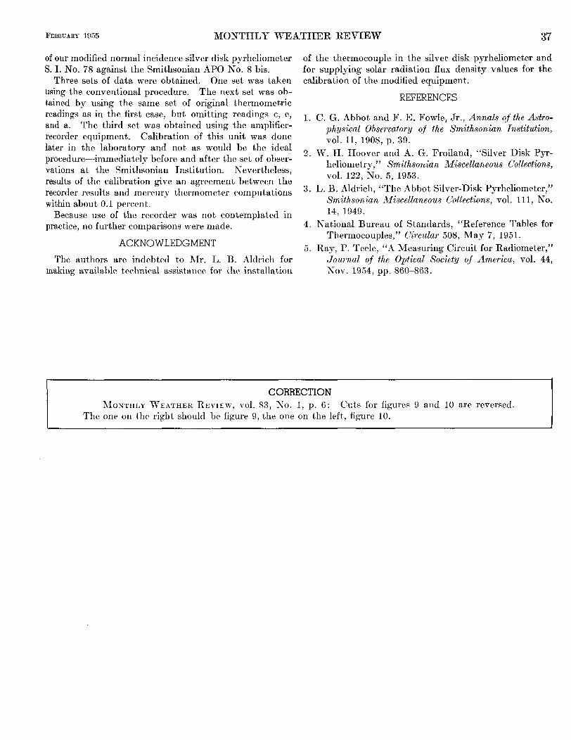
of our modified normal incidence silver disk pyrheliometer S. I. No. 78 against the Smithsonian APO No. 8 bis.
Three sets of data were obtained. One set was taken using the conventional procedure. The next set was ob- tained by using the same set of original thermometric readings as in the first case, but omitting readings c , e, and a. The third set was obtained using the amplifier- recorder equipment. Calibration of this unit was done later in the laboratory and not as would be the ideal procedure--immediately before and after the set of obser- vations at the Smithsonian Institution. Nevertheless, results of the calibration give an agreement between the recorder results and mercury thermomet,er c.omputations within about 0.1 percent.
Because use of the recorder was not conternplatcd in practice, no further comparisons were made.
ACKNOWLEDGMENT The authors are indebted to Mr. L. B. Aldrich for
making available technical assistance for the installation
of the thermocouple in the silver disk pyrheliometer and for supplying solar radiation flux density values for the calibration of the modified equipment.
REFERENCES
1. C. G. Abbot and F. E. Fowle, Jr., Annals of the Astro- physical Observatory of the Srnithsonian Institution,
2. W. H. Hoover and A. G. Froiland, “Silver Disk Pyr- heliometry,” Srnithsonian Miscellaneous Collections, vol. 122, No. 5, 1953.
3, L. B. Aldrich, “The Abbot Silver-Disk Pyrheliometer,” Smithsonian Miscellaneous Collections, vol. 11 1 , No. 14, 1949.
4. National Bureau of St,andards, “Reference Tables for Thermocouples,” Circular 508, May 7, 1951.
5. Ray, P. Teele, “A Measuring Circuit for Radiometer,” Journal of the Optical Society of America, vol. 44,
vol. 11, 1908, p. 39.
XOV. 1954, pp. 860-863.
CORRECTION MORTTHLY WEATHER REVIEW, vol. 83, KO. I , p. 6: Cut’s for figures 9 and 10 are reversed.
The one on t,he right should be figure 9, t,he one on the left, figure 10.