Embed Size (px)
Citation preview

Department of Civil Engineering
B.TECH – 5TH SEM
DCS

Module-I
Properties of concrete and reinforcing steel, Philosophy, concept and methods of reinforced
concrete design, Introduction to limit state method: Limit state of collapse and limit state of
serviceability. Application of Limit state method to rectangular beams for flexure, shear, bond and
torsion.

Introduction
Reinforced concrete, as a composite material, has occupied a special place in the modern
construction of different types of structures due to its several advantages. Due to its flexibility in
form and superiority in performance, it has replaced, to a large extent, the earlier materials like
stone, timber and steel. Further, architect's scope and imaginations have widened to a great extent
due to its mouldability and monolithicity. Thus, it has helped the architects and engineers to build
several attractive shell forms and other curved structures. However, its role in several straight line
structural forms like multistoried frames, bridges, foundations etc. is enormous.
Concrete
Concrete is a product obtained artificially by hardening of the mixture of cement, sand, gravel and
water in predetermined proportions.
Depending on the quality and proportions of the ingredients used in the mix the properties of
concrete vary almost as widely as different kinds of stones.
Concrete has enough strength in compression, but has little strength in tension. Due to this,
concrete is weak in bending, shear and torsion. Hence the use of plain concrete is limited
applications where great compressive strength and weight are the principal requirements and
where tensile stresses are either totally absent or are extremely low.
PROPERTIES OF FRESH CONCRETE
Workability
Workability is the ease with which the concrete can be mixed, placed, consolidated and
finished.
Workable concrete is the one which exhibits very little internal friction between particle and
particle or which overcomes the frictional resistance offered by the formwork surface or
reinforcement contained in the concrete.
The factors affecting workability are given below:
Water Content
Mix Proportions
Size of Aggregates
Shape of Aggregates
Surface Texture of Aggregate
Grading of Aggregate

Use of Admixtures
The following tests are commonly employed to measure workability.
• Slump Test
• Compacting Factor Test
• Flow Test
• Kelly Ball Test
• VeeBee Consistometer Test
Segregation
Segregation can be defined as the separation of the constituent materials of concrete.
A good concrete has all its constituents properly distributed to form a homogenous mixture. To
ensure this, optimum grading, size, shape and surface texture of aggregates with optimum quantity
of cement & water makes a mix cohesive. Such a concrete does not exhibit the tendency for
segregation.
Prime cause of segregation is the difference in specific gravity of constituents of concrete.
Segregation may be one of the following types:
1. Coarse aggregate separating out of the rest
2. Cement paste or cement-fine aggregate matrix separating out from coarse aggregate
3. Water separating out of the rest
The conditions that favour segregation are:
• Bad mix proportion
• Inadequate mixing
• Excessive compaction by vibration of wet mix
• Large height of dropping of concrete for placement
• Long distance conveyance of mix
Bleeding
Here, water from the concrete comes out to the top surface of the concrete after casting.
The conditions that favour bleeding are:
o Highly wet mix
o Bad mix proportion o Inadequate mixing
Sometimes, the bleeding water is accompanied to the surface by certain quantity of cement,
which forms a cement paste (known as Laitance) at the surface.
PROPERTIES OF HARDENED CONCRETE
Grade of concrete

Designated in terms of letter ‘M’ followed by a number. ‘M’ refers to mix; the number
represents the 28-day characteristic compressive strength of concrete cubes (150mm)
expressed in MPa.
Eg: M20 denotes the concrete mix with 28-day characteristic compressive strength of
20MPa.
Minimum grade of concrete used is dictated by durability (the environment to which the
structure is exposed to, expressed in terms of exposure conditions)
• Classification
o Ordinary concrete – M10 to M20
o Standard concrete – M25 to M55
o High Strength concrete – M60 and above
Stress-strain curve of concrete
• Stress-Strain curves of concrete for various grades obtained from uniaxial
compression tests are shown in above figure
• Maximum stress is attained by concrete at an approximate strain of 0.002
• The strain at failure is in the range 0.003 to 0.005
• The curves are linear within the initial portion of the curve. This is
approximately true upto one-third of the maximum stress level, beyond
which the non-linearity continues
• For higher grades of concrete, the initial portion of the stress-strain curve is
steeper, but the failure strain is low. For low strength concrete, the initial
slope of curve is gentle but has high failure strain. (observe the figure)
Exposure Condition
Minimum grade of concrete for RCC works
Mild M20
Moderate M25
Severe M30
Very severe
M35
Extreme M40

• Poisson Effect: Failure of concrete subject to uniaxial compression is
primarily initiated by longitudinal cracks (cracks developed parallel to
direction of loading) formed due to lateral expansion (because lateral fibres
experience tensile stress) and finally lateral strain exceeds limiting tensile
strain of concrete of 0.0001 to 0.0002. These longitudinal cracks generally
occur at coarse aggregate-mortar interface.
• The descending part of Stress-Strain curve is attributed to the extensive
microcracking in mortar. This is called Strain-Softening of Concrete.
Modulus of Elasticity of concrete
• Young’s Modulus of Elasticity (equal to ratio of stress to strain, when the
material is loaded within the linearly elastic limit) for concrete subjected to
uniaxial compression, has validity only within the initial portion of the
Stress-Strain curve. For concrete, there are 3 ways to determine the Modulus
of Elasticity. This is shown in figure.
o Initial Tangent Modulus – Slope of tangent at origin of curve; measure of
Dynamic Modulus of Elasticity of concrete
o Tangent Modulus – Slope of tangent at any point on the curve
o Secant Modulus – slope of line joining origin & one-third of maximum

stress level; measure of Static Modulus of Elasticity of concrete
• Static Modulus of Elasticity of concrete – is applicable to static system of
loads on structures
• Dynamic Modulus of Elasticity of concrete – is applicable when structure is
subject to dynamic loads (wind & earthquake loads)
• Secant Modulus at one-third of maximum stress level represents the “Short-
term Static Modulus of Elasticity of Concrete (Ec)”. “Short-term” means the
long term effects of creep & shrinkage are not considered.
• According to IS456,
Ec=5000√fck N/mm2
Where fck is the 28-day characteristic compressive strength of 150mm
concrete cubes. Thus, it should be noted that Modulus of Elasticity of
concrete is a function of its strength.
Creep of concrete Creep is another time dependent deformation of concrete by which it continues to deform,
usually under compressive stress. The creep strains recover partly when the stresses are
released.
θ=creep co-efficient
Ecr = Ec /(1+ θ)
PROPERTIES OF STEEL
Stress-strain curve of reinforcing steel
• Reinforcing steel may be categorized broadly into:
o Plain Mild steel bars
has well-defined yield point
Eg: Fe250 – Yield strength= 250MPa; Ultimate strength=
412MPa; Min % elongation= 22%
o High Yield Strength Deformed bars
Does not have well-defined yield point
these are cold-worked bars (involves stretching and twisting of
mild steel bars)
Eg: Fe415 – Yield strength= 415MPa; Ultimate strength=
485MPa; Min % elongation= 14.5%
Eg: Fe500 – Yield strength= 500MPa; Ultimate strength=
545MPa; Min % elongation= 12%

• Characteristic strength of reinforcing steel =
o yield strength of steel– for those with well-defined yield point (Fe250)
o 0.20% Proof Stress – for those without well-defined yield point
(Fe415&Fe500)
• 0.2% Proof Stress is measured as shown below
Method of RCC design
A reinforced concrete structure should be designed to satisfy the following criteria-
i) Adequate safety, in items stiffness and durability
iii) Reasonable economy.
The following design methods are used for the design of RCC Structures.
a) The working stress method (WSM)
b) The ultimate load method (ULM)
c) The limit state method (LSM)
Working Stress Method (WSM)
This method is based on linear elastic theory or the classical elastic theory. This method ensured
adequate safety by suitably restricting the stress in the materials (i.e. concrete and steel) induced
by the expected working leads on the structures. The assumption of linear elastic behaviour
considered justifiable since the specified permissible stresses are kept well below the ultimate
strength of the material. The ratio of yield stress of the steel reinforcement or the cube strength
of the concrete to the corresponding permissible or working stress is usually called factor of
safety.

The WSM uses a factor of safety of about 3 with respect to the cube strength of concrete and a
factor of safety of about 1.8 with respect to the yield strength of steel.
Ultimate state method (USM)
The method is based on the ultimate strength of reinforced concrete at ultimate load is obtained
by enhancing the service load by some factor called as load factor for giving a desired margin
of safety .Hence the method is also referred to as the load factor method or the ultimate strength
method.
In the ULM, stress condition at the state of in pending collapse of the structure is analysed, thus
using, the non-linear stress – strain curves of concrete and steel. The safely measure in the
design is obtained by the use of proper load factor. The satisfactory strength performance at
ultimate loads does not guarantee satisfactory strength performance at ultimate loads does not
guarantee satisfactory serviceability performance at normal service loads.
Limit state method (LSM)
Limit states are the acceptable limits for the safety and serviceability requirements of the
structure before failure occurs. The design of structures by this method will thus ensure that
they will not reach limit states and will not become unfit for the use for which they are
intended. It is worth mentioning that structures will not just fail or collapse by violating
(exceeding) the limit states. Failure, therefore, implies that clearly defined limit states of
structural usefulness has been exceeded.
Limit state are two types
i) Limit state of collapse
ii) Limit state of serviceability.
Limit states of collapse
The limit state of collapse of the structure or part of the structure could be assessed
from rupture of one or more critical sections and from bucking due to elastic bending, shear,
torsion and axial loads at every section shall not be less than the appropriate value at that
section produced by the probable most unfavourable combination of loads on the structure
using the appropriate factor of safely.

Limit state of serviceability
Limit state of serviceability deals with deflection and crocking of structures under service
loads, durability under working environment during their anticipated exposure conditions
resistance during service, stability of structures as a whole, fire etc.
Characteristic and design values and partial safety factor
1. Characteristic strength of materials.
The term characteristic strength‘ means that value of the strength of material below which
not more than minimum acceptable percentage of test results are expected to fall. IS 456:2000
have accepted the minimum acceptable percentage as 5% for reinforced concrete structures.
This means that there is 5% for probability or chance of the actual strength being less than the
characteristic strength.
Figure shows frequency distribution curve of strength material (concrete or steel). The value of
K corresponding to 5% area of the curve is 1.65.
The design strength should be lower than the mean strength (fm)
Characteristic strength = Mean strength –K * standard deviation or
fk=fm-KSd
Where, fk=characteristic strength of the material
fm=mean strength

K=constant =1.65
Sd=standard deviation for a set of test results.
The value of standard deviation (Sd) is given by
Where, δ=deviation of the individual test strength from the average or mean strength of n
samples.
n= number of test results.
IS 456:2000 has recommended minimum value of n=30.
Characteristic strength of concrete
Characteristic strength of concrete is denoted by fck (N/mm2) and its value is different for
different grades of concrete e.g. M 15, M25 etc. In the symbol M used for designation of
concrete mix, refers to the mix and the number refers to the specified characteristic
compressive strength of 150 mm size cube at 28 days expressed in N/mm2
Characteristic strength of steel
Until the relevant Indian Standard specification for reinforcing steel are modified to include the
concept of characteristic strength, the characteristic value shall be assumed as the minimum
yield stress or 0.2% proof stress specified in the relevant Indian Standard specification. The
characteristic strength of steel designated by symbol fy (N/mm2)
Characteristic loads
The term Characteristic load means that values of load which has a 95% probability of not
being exceeded during that life of the structure.

The design load should be more than average load obtained from statistic, we have
Fk=Fm+KSd
Where, Fk=characteristic load;
Fm= mean load
K=constant=2.65;
Sd=standard deviation for the load.
Since data are not available to express loads in statistical terms, for the purpose of this
standard, dead loads given in IS 875(Part-1), imposed loads given in IS 875(Part-2), wind loads.
Given in IS 875 (Part-3), snow load as given in IS 875(Part-4) and seismic forces given in IS
1893 shall be assumed as the characteristic loads.
Design strength of materials
The design strength of materials (fd) is given by

Design loads
The design load ( Fd) is given by.
Fd=Fk. y f
y f =partial safety factor appropriate to the nature of loading and the limit state being
considered.
The design load obtained by multi plying the characteristic load by the partial safety factor for
load is also known as factored load.
Partial safety factor ( ym) for materials
When assessing the strength of a structure or structural member for the limit state of collapse,
the values of partial safety factor, y m should be taken as 1.15 for steel.
Thus, in the limit state method , the design stress for steel reinforcement is given by
fy / y ms = fy/1.15=0.87fy.
According to IS 456:2000 for design purpose the compressive strength of concrete in the
structure shall be assumed to be 0.67 times the characteristic strength of concrete in cube and
partial safety factor ymc =1.5 shall be applied in addition to this. Thus, the design stress in
concrete is given by
0.67 fck /ymc = 0.67 fck /1.5 = 0.446 fck
Partial safety factor for loads
The partial safety factors for loads, as per IS 456:2000 are given in table below
Load
combination
Limit State of collapse Limit State of Serviceability
DL LL WL/EL DL LL WL/EL
DL+IL 1.5 1.5 - 1.0 1.0 -
DL+WL 1.5 or 0.9* - 1.5 1.0 - 1.0
DL+IL+WL 1.2 1.2 1.2 1.0 0.8 0.8
(* This value is to be considered when stability against overturning or stress reversal is critical)
LIMIT STATE METHOD
• The acceptable limit for safety and serviceability requirements before failure occurs
is known as Limit State.
• LSM involves underestimation of the material strength and overestimation of
external loads. For this, the method uses partial safety factor format.
The design of any structure should satisfy the following 2 conditions:
SAFETY
• With due consideration to strength, stability & structural integrity.
• If this condition is satisfied, the likelihood for “collapse” is acceptably low under
service loads (usual or expected loads) as well as probable overloads (extreme winds,
earthquake etc.)
• Collapse may occur due to:
o Exceeding of strength of material or load bearing capacity of material.
o Sliding
o Overturning
o Buckling
o Fatigue
o Fracture
• Limit states involved in collapse are called “Limit State of Collapse” or “Ultimate
Limit State”, which are defined for the following,
• Flexure
• Compression
• Shear
• Torsion
SERVICEABILITY
• Satisfactory performance of structure under service loads. Ensures no discomfort
to the user
• If this condition is satisfied, the likelihood for “user discomfort” is acceptably low
under service loads.
• User discomfort may occur due to:
o Deflection

o Cracking
o Vibrations
o Durability
o Impermeability
o Thermal Insulation (or Fire resistance)
• Limit states involved in user comfort are called “Limit state of serviceability”,
which are defined for,
o Deflection
o Cracking
o Durability
o Fire Resistance
Limit state of collapse in flexure
The behaviour of reinforced concrete beam sections at ultimate loads has been explained in
detail in previous section. The basic assumptions involved in the analysis at the ultimate limit
state of flexure (Cl. 38.1 of the Code) are listed here.
a) Plane sections normal to the beam axis remain plane after bending, i.e., in an initially
straight beam, strain varies linearly over the depth of the section.
b) The maximum compressive strain in concrete (at the outermost fibre)
0.0035 in bending.
Ec shall be taken as
c) The relationship between the compressive stress distribution in concrete and the strain in
concrete may be assumed to be rectangle, trapezoid, parabola or any other shape which results
in prediction of strength in substantial agreement with the results of test. An acceptable stress-
strain curve is given below in figure For design purposes, the compressive strength of concrete
in the structure shall be assumed to be 0.67 times the characteristic strength. The partial safety
factor ym = 1.5 shall be applied in addition to this.

Figure 1.6 Stress-strain curve for concrete
d) The tensile strength of the concrete is ignored.
e) The stresses in the reinforcement are derived from representative stress-strain curve for the
type of steel used. Typical curves are given in figure 1.3. For design purposes the partial
safety factor ym equal to 1.15 shall be applied.
f) The maximum strain in the tension reinforcement in the section at failure shall not be less
than:
Limiting Depth of Neutral Axis
Rectangular beam under flexure xu < xu,max

Rectangular beam under flexure xu = xu,max
Based on the assumption given above, an expression for the depth of the neutral axis at the
ultimate limit state, xu , can be easily obtained from the strain diagram in Fig. 1.8. Considering
similar triangles,

ANALYSIS OF SINGLY REINFORCED RECTANGULAR SECTIONS
• The Concrete Stress block (Compressive stress distribution in concrete at ultimate limit state) is
analysed as follows:
Fig. 1.9 Concrete stress-block parameters in compression
In order to determine the magnitude of Cu and its line of action, it is necessary to analyse the concrete stress
block in compression. As ultimate failure of a reinforced concrete beam in flexure occurs by the crushing of
concrete, for both under- and over-reinforced beams, the shape of the compressive stress distribution (stress
block‘) at failure will be, in both cases, as shown in Fig. 1.9. The value of Cu can be computed knowing that
the compressive stress in concrete is uniform at 0.447 fck for a depth of 3xu / 7, and below this it varies
parabolically over a depth of 4xu / 7 to zero at the neutral axis
Also, the line of action of Cu is determined by the centroid of the stress block, located at a distance from the
concrete fibres subjected to the maximum compressive strain. Accordingly, considering moments of
compressive forces Cu, C1 and C2 about the maximum compressive strain location

Depth of Neutral Axis
Compressive force C = 0.36 fck b xu
Tensile force T = 0.87 fy Ast
Lever arm (i.e., the perpendicular distance between line of action of compressive force
and tensile force) z = d – 0.42 xu
For any given section, since the forces are in equilibrium, C = T
Therefore, depth of neutral axis is obtained as
ULTIMATE MOMENT OF RESISTANCE
LIMITING MOMENT OF RESISTANCE

Modes of failure: Types of section
A reinforced concrete member is considered to have failed when the strain of concrete in extreme
compression fibre reaches its ultimate value of 0.0035. At this stage, the actual strain in steel can have the
following values:
In balanced section,
The strain in steel and strain in concrete reach their maximum values simultaneously. The percentage of steel
in this section is known as critical or limiting steel percentage. The depth of neutral axis (NA) is Xu =Xu, max
Under-reinforced section
An under-reinforced section is the one in which steel percentage (pt) is less than critical or limiting
percentage ( pt,lim ). Due to this the actual NA is above the balanced NA and
Xu<Xumax
Over-reinforced section
In the over reinforced section the steel percentage is more than limiting percentage due to which NA falls
below the balanced NA and Xu >Xu,max . . Because of higher percentage of steel, yield does not take place in
steel and failure occurs when the strain in extreme fibres in concrete reaches its ultimate value.
Design Type of Problems
The designer has to make preliminary plan lay out including location of the beam, its span and spacing,
estimate the imposed and other loads from the given functional requirement of the structure. The dead loads
of the beam are estimated assuming the dimensions b and d initially. The bending moment, shear force and
axial thrust are determined after estimating the different loads. In this illustrative problem, let us assume that
the imposed and other loads are given. Therefore, the problem is such that the designer has to start with some
initial dimensions and subsequently revise them, if needed. The following guidelines are helpful to assume
the design parameters initially.
(i) Selection of breadth of the beam b
Normally, the breadth of the beam b is governed by: (i) proper housing of reinforcing bars and (ii)
architectural considerations. It is desirable that the width of the beam should be less than or equal to the width
of its supporting structure like column width, or width of the wall etc. Practical aspects should also be kept in
mind. It has been found that most of the requirements are satisfied with b as 150, 200, 230, 250 and 300 mm.
Again, width to overall depth ratio is normally kept

between 0.5 and 0.67.
(ii) Selection of depths of the beam d and D
The effective depth has the major role to play in satisfying (i) the strength requirements of bending moment
and shear force, and (ii) deflection of the beam. The initial effective depth of the beam, however, is assumed
to satisfy the deflection requirement depending on the span and type of the reinforcement. IS 456 stipulates
the basic ratios of span to effective depth of beams for span up to 10 m as (Clause 23.2.1)
Cantilever 7
Simply supported 20
Continuous 26
For spans above 10 m, the above values may be multiplied with 10/span in metres, except for cantilevers
where the deflection calculations should be made. Further, these ratios are to be multiplied with the
modification factor depending on reinforcement percentage and type. Figures 4 and 5 of IS 456 give the
different values of modification factors. The total depth D can be determined by adding 40 to 80 mm to the
effective depth.
(iii) Selection of the amount of steel reinforcement Ast
The amount of steel reinforcement should provide the required tensile force T to resist the factored moment
Mu of the beam. Further, it should satisfy the minimum and maximum percentages of reinforcement
requirements also. The minimum reinforcement As is provided for creep, shrinkage, thermal and other
environmental requirements irrespective of the strength requirement. The minimum reinforcement As to be
provided in a beam depends on the f y of steel and it follows the relation: (cl. 26.5.1.1a of IS 456)
The maximum tension reinforcement should not exceed 0.04 bD (cl. 26.5.1.1b of IS 456), where D is the total
depth.
Besides satisfying the minimum and maximum reinforcement, the amount of reinforcement of the singly
reinforced beam should normally be 75 to 80% of Pt,lim. Moreover, in many cases, the depth required for
deflection becomes more than the limiting depth required to resist Mu, lim. Thus, it is almost obligatory to
provide more depth. Providing more depth also helps in the amount of the steel which is less than that

required for Mu, lim. This helps to ensure ductile failure. Such beams are designated as under-reinforced
beams.
(iv) Selection of diameters of bar of tension reinforcement
Reinforcement bars are available in different diameters such as 6, 8, 10, 12, 14, 16, 18, 20, 22, 25, 28, 30, 32,
36 and 40 mm. Some of these bars are less available. The selection of the diameter of bars depends on its
availability, minimum stiffness to resist while persons walk over them during construction, bond requirement
etc. Normally, the diameters of main tensile bars are chosen from 12, 16, 20, 22, 25 and 32 mm.
(v) Selection of grade of concrete
Besides strength and deflection, durability is a major factor to decide on the grade of concrete. Table 5 of IS
456 recommends M 20 as the minimum grade under mild environmental exposure and other grades of
concrete under different environmental exposures also.
(vi) Selection of grade of steel
Normally, Fe 250, 415 and 500 are in used in reinforced concrete work. Mild steel (Fe 250) is more ductile
and is preferred for structures in earthquake zones or where there are possibilities of vibration, impact, blast
etc.

DESIGN FOR SHEAR
STRESSES IN HOMOGENOUS RECTANGULAR BEAMS
From basic mechanics of materials, it is known that the flexural (bending) stress fx and the shear stress
Ƭ at any point in the section, located at a distance y from the neutral axis, are given by:
where I is the second moment of area of the section about the neutral axis, Q the first moment of area
about the Neutral Axis of the portion of the section above the layer at distance y from the NA, and b is
the width of the beam at the layer at which Ƭ is calculated.
Consider an element at a distance y from the Neutral Axis (NA).
The combined flexural and shear stresses on that element can be resolved into equivalent
principal stresses f1 and f2 acting on orthogonal planes.
As a result, the stress on the beam is depicted in terms of the principal stress trajectories as shown.

In a material like concrete which is weak in tension, tensile cracks would develop in a direction that is
perpendicular to that of the principal tensile stress. Thus the compressive stress trajectories in the above
figure indicate potential crack patterns, as shown below.
Potential crack patterns
MODES OF CRACKING
1) Flexural cracks
• Occurs in reinforced concrete beams of usual proportions, subjected to relatively high flexural
stresses fx and low shear stresses Ƭ.
• Maximum principal tensile stress occurs in the outer fibre at the bottom face of the concrete beam at
the peak moment locations. As a result, cracks are formed, which are termed as flexural cracks.
• These are formed at 90o from the extreme tension fibre towards neutral axis.
• These are controlled by the tension bars.
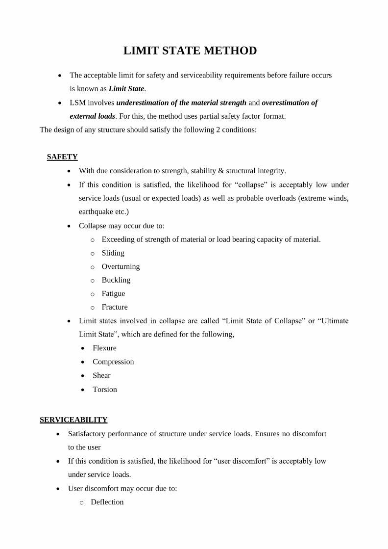
2) Diagonal Tension Cracks / Web shear cracks
Occurs in beams which are subjected to high shear stresses Ƭ (due to heavy concentrated loads) and
relatively low flexural stresses fx (such as, short−span beams which are relatively deep and have thin webs).
It is likely that the maximum principal tensile stress is located at the neutral axis level at an inclination α=
45o (to the longitudinal axis of the beam)
• Cracks occur near the supports (where shear force is generally maximum) near neutral axis and
inclined at 45o to the longitudinal axis of the beam. These are termed as web shear cracks or
diagonal tension cracks.
• These can be resisted by providing shear reinforcements or stirrups.
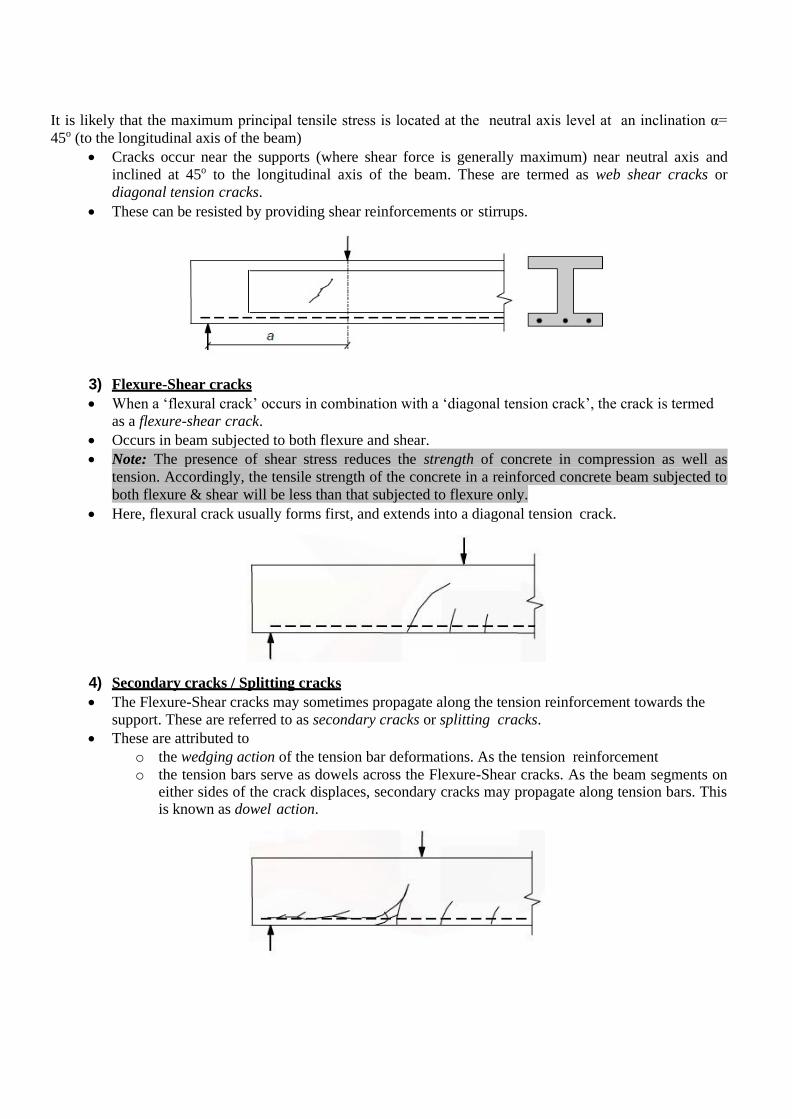
3) Flexure-Shear cracks
• When a ‘flexural crack’ occurs in combination with a ‘diagonal tension crack’, the crack is termed
as a flexure-shear crack.
• Occurs in beam subjected to both flexure and shear.
• Note: The presence of shear stress reduces the strength of concrete in compression as well as
tension. Accordingly, the tensile strength of the concrete in a reinforced concrete beam subjected to
both flexure & shear will be less than that subjected to flexure only.
• Here, flexural crack usually forms first, and extends into a diagonal tension crack.
4) Secondary cracks / Splitting cracks
• The Flexure-Shear cracks may sometimes propagate along the tension reinforcement towards the
support. These are referred to as secondary cracks or splitting cracks.
• These are attributed to
o the wedging action of the tension bar deformations. As the tension reinforcement
o the tension bars serve as dowels across the Flexure-Shear cracks. As the beam segments on either sides of the crack displaces, secondary cracks may propagate along tension bars. This is known as dowel action.

SHEAR PARAMETERS FOR DESIGN
1) Nominal Shear Stress
• For prismatic members of rectangular (or flanged) sections, the Code (Cl. 40.1) uses the term
nominal shear stress Ƭv, defined at the ultimate limit state, as
where Vu is the factored shear force at the section under consideration, b is the width of the beam
(taken as the web width bw in flanged beams), and d the effective depth of the section.
• In the case of members with varying depth, the nominal shear stress, defined above, needs to be
modified, to account for the contribution of the vertical component of the flexural tensile force Tu
which is inclined at an angle β to the longitudinal direction.
Accordingly, the nominal shear stress (Cl. 40.1.1 of the Code), is obtained as
where Vu and Mu are the applied factored shear force and bending moment at the section under
consideration. The negative sign applies where Mu increases in the same direction as the depth
increases and the positive sign applies where Mu decreases in this direction, as shown below.

2) Critical Sections for shear
Critical sections are those sections at which shear force is maximum.
Location of critical sections for different cases are shown below. [Refer Cl. 22.6.2]
3) Design Shear Strength of Concrete in Beams (Ƭc)
• It is the average shear strength of concrete in reinforced concrete beams without shear
reinforcement. It is the stress that corresponds to the load at which the first inclined crack
develops.
• If the shear stress in beam Ƭv is less than Ƭc, shear reinforcements are not to be designed (only
minimum shear reinforcements shall be provided). But if Ƭv > Ƭc, shear reinforcements shall be
designed.
• Therefore, Ƭc is the safe limiting value below which the beam is safe even without shear
reinforcement.
• Ƭc depends on grade of concrete (fck) and the percentage tension steel pt = 100Ast/(bd). The
values of Ƭc are given in the Code (Refer Table 19).

• Shear strength of slabs is higher than that of beams, owing to small thickness. The thinner the
slab, the greater is the increase in shear strength. The Code (Cl. 40.2.1.1) suggests an increased
shear strength for slabs, equal to k Ƭc, where the multiplication factor k ranges between 1 and
1.3. In general, slabs subjected to normal distributed loads satisfy the requirement Ƭv <
Ƭc, and hence do not need shear reinforcement.
4) Types of Shear Reinforcement
• Shear reinforcement, also known as web reinforcement may consist of any one of the following
systems (Cl. 40.4 of the Code)
a) stirrups perpendicular to the beam axis;
b) stirrups inclined (at 45° or more) to the beam axis; and
c) longitudinal bars bent-up (usually, not more than two at a time) at 45° to 60° to the beam axis,
combined with stirrups.
• By far, the most common type of shear reinforcement is the two-legged stirrup, comprising a closed
or open loop, with its ends anchored properly around longitudinal bars/stirrup holders (to develop the
yield strength in tension). It is placed perpendicular to the member axis (‘vertical stirrup’), and may
or may not be combined with bent-up bars.
• Where bent-up bars are provided, their contribution towards shear resistance shall not be more than
half that of the total shear reinforcement.
5) Limiting Ultimate Shear Strength of beam (Ƭc,max)
• The nominal shear stress (Ƭv) on the beam should not exceed the limiting total shear
strength of beam including shear reinforcement (Ƭc,max).
• Such a limit is set to the shear stress in beam Ƭv because : if the shear reinforcement
Provided in the section is excessive, failure may occur by crushing of concrete (known as
shear-compression failure which occurs due to crushing of the reduced concrete section
after formation of flexure-shear crack), even before yielding of shear reinforcements. Since
this is a brittle fracture, such a failure is undesirable.
• Thus by limiting the shear stress in beam Ƭv to less than Ƭc,max, shear-compression failures
can be prevented.
• Values of Ƭc,max is given in Table 20 of IS456. It may also be obtained from the following
approximate relation.
• In the case of solid slabs, the Code (Cl. 40.2.3.1) specifies that Ƭv should not exceed
0.5 Ƭc,max .
6) Design of shear reinforcement
If Ƭv > Ƭc
• Design as per Cl. 40.4 of IS456
• Provide shear reinforcements in any of the following forms – vertical stirrups, Inclined Stirrups
and Bent-up bars with stirrups
• Shear force to be resisted by stirrups Vus = Vu - Ƭc b d
• If vertical stirrups are used, center-to-center spacing of the stirrups along the length of the
member, Sv is determined from:
Where Asv is the cross-sectional area of stirrup legs or bent-up bars.
• For vertical stirrups, the maximum spacing between stirrups is limited as follows:

• For inclined stirrups or a series of bars bent-up at different cross-sections:
• For single bar or single group of parallel bars, all bent-up at the same cross-section:
where Asv = total cross-sectional area of stirrup legs or bent-up bars within a distance sv,
sv = spacing of stirrups or bent-up bars along the length of the member,
Tv = nominal shear stress,
Tc = design shear strength of concrete,
b = breadth of the member which for the flanged beams shall be taken as the breadth of the web bw,
fy = characteristic strength of the stirrup or bent-up reinforcement which shall not be taken greater than 415
N/mm2,
α = angle between the inclined stirrup or bent-up bar and the axis of the member, not less than 45o, and
d = effective depth.
If Ƭv < Ƭc
• If Ƭv < 0.5 Ƭc
No shear reinforcement is required.
• If Ƭv > 0.5 Ƭc
The Code (Cl. 26.5.1.6) specifies a minimum shear reinforcement to be provided in the form of
stirrups.

BOND
The bond between steel and concrete is very important and essential so that they can act together
without any slip in a loaded structure. With the perfect bond between them, the plane section of a
beam remains plane even after bending. The length of a member required to develop the full bond
is called the anchorage length. The bond is measured by bond stress. The local bond stress varies
along a member with the variation of bending moment.
Thus, a tensile member has to be anchored properly by providing additional length on either side
of the point of maximum tension, which is known as Development length in tension. Similarly, for
compression members also, we have Development length Ld in compression‘.
Accordingly, IS 456, cl. 26.2 stipulates the requirements of proper anchorage of reinforcement in
terms of development length Ld only employing design bond stress 𝜏bd.
Design bond stress – values
The average bond stress is still used in the working stress method and IS 456 has mentioned about
it in cl. B-2.1.2. However, in the limit state method of design, the average bond stress has been
designated as design bond stress τbd and the values are given in cl. 26.2.1.1. The same is given
below as a ready reference.
Table 5: τbd for plain bars in tension
Grade of concrete M 20 M 25 M 30 M 35 M 40 and above
Design Bond Stress
τbd in N/mm2
1.2 1.4 1.5 1.7 1.9
For deformed bars conforming to IS 1786, these values shall be increased by 60 per cent. For
bars in compression, the values of bond stress in tension shall be increased by 25 per cent.
Development Length
Figure 1.13 Development length of bar
Figure 1.13 shows the free body diagram of the segment AB of the bar. At B, the tensile force T is

the tensile force trying to pull out the bar. It is necessary to have the resistance force to be
developed by τbd for the length Ld to overcome the tensile force. Equating the two, we get
The above equation is given in cl. 26.2.1 of IS 456 to determine the development length of bars.
The example taken above considers round bar in tension. Similarly, other sections of the bar
should have the required Ld as determined for such sections. For bars in compression, the
development length is reduced by 25 per cent as the design bond stress in compression τbd is 25
per cent more than that in tension. Following the same logic, the development length of deformed
bars is reduced by 60 per cent of that needed for the plain round bars. Tables 64 to 66 of SP-16
present the development lengths of fully stressed plain and deformed bars (when σs = 0.87 fy) both
under tension and compression. It is to be noted that the consequence of stress concentration at the
lugs of deformed bars has not been taken into consideration.
Checking of Development Lengths of Bars in Tension
The following are the stipulation of cl. 26.2.3.3 of IS 456.
(i) At least one-third of the positive moment reinforcement in simple members and one-fourth of
the positive moment reinforcement in continuous members shall be extended along the same face
of the member into the support, to a length equal to Ld/3.
(ii) Such reinforcements of (i) above shall also be anchored to develop its design stress in tension
at the face of the support, when such member is part of the primary lateral load resisting system.
(iii) The diameter of the positive moment reinforcement shall be limited to a diameter such that
the Ld computed for σs = fd does not exceed the following:
where M1 = moment of resistance of the section assuming all reinforcement at the section to be
stressed to fd,
fd = 0.87 fy,
V = shear force at the section due to design loads,
Lo = sum of the anchorage beyond the centre of the support and the equivalent anchorage value of
any hook or mechanical anchorage at simple support. At a point of inflection, Lo is limited to the
effective depth of the member or 12θ, whichever is greater, and

θ = diameter of bar.
It has been further stipulated that M1/V in the above expression may be increased by 30 per cent
when the ends of the reinforcement are confined by a compressive reaction.
Numerical problem of design of singly reinforced beam
A reinforced concrete beam is supported on two walls 250mm thick, spaced at a clear distance of
6m. The beam carries a super-imposed load of 9.8 KN/m. design the beam using M20 concrete
and HYSD bars of Fe 415 grade.
SOLUTION
Now from experience, assume d=l/15=400mm
Therefore, overall depth= effective depth+ clear cover + diameter of stirrup +0.5(diameter of
main reinforcement)
=400+25+8+0.5x20=443mm 450mm
Assume b=250mm
Therefore, try a trial section of dimension 250x450.
Load Calculation
Self-weight of beam (DL)= 0.25x0.45x1x25=2.8125 KN/m
Super-imposed load (LL)= 9.8 KN/m
Therefore, total load, w =(DL+LL)=(2.8125+9.8)=12.6125 KN/m
Design load, wu =1.5x w=18.9187 KN/m
Calculation of effective span
As per IS 456:2000, cl no 22.2 (a), the effective span of a simply supported beam is lesser of
the following two.
Clear span+ the effective depth of beam or slab
Or centre to centre distance between supports.
Clear span =6m
Effective depth of beam, d=450-25-8-0.5x20=407mm
Therefore, clear span + effective depth of beam=(6+0.407)m=6.407m
Centre to centre distance between support=(6+0.25/2+0.25/2)m=6.25m
Lesser of two=6.25m
Therefore, effective span =6.25m
Calculation of BM and SF

Computation of effective depth, d
For M20 grade of concrete and Fe 415 grade of steel
Now assumed depth was =407mm
Therefore, required< assumed
So, the section assumed is safe from bending moment point of view.
Since the available depth (407mm) is greater than required depth (365.89mm). So the section is
under reinforced.
Calculation of steel reinforcement
The reinforcement for an under-reinforced section is given by
Shear Reinforcement
As per IS 456:2000 Cl. No. 22.6.2, the critical section for shear is at a distance of d from the face
of the support.
So, shear force at that distance, Vu =59.12-18.9187(0.25/2+0.407) = 49.05 KN.
As per IS 456:2000, table 19, the design shear strength of concrete, for %pt=0.926 and M20 grade
of concrete, τc =0.61 N/mm2
Since τv<τc, no shear reinforcement is necessary. However, minimum shear reinforcement as per

cl no 26.5.1.6 of IS 456:2000 should be provided.
As per cl no 26.5.1.5 of IS 456:2000, maximum spacing of shear reinforcement least of the
following
(a) 0.75d or (b) 300mm
Hence provide 2-8 mm diameter @ 300mm c/c throughout the length of the beam.
Check for Development length
As per cl no 26.2.1 of IS 456:2000, the development length Ld is given by
Now as per cl no 26.2.3.3 (c) of IS 456:2000, at a simple support and at points of inflection,
positive moment tension reinforcement shall be limited to a diameter such that Ld computed for fd
does not exceed
The value of in the above expression M1/V may be increased by 30% when the ends of the
reinforcement are confined by a compressive reaction.

450mm
Reinforcement Detailing
2-10 2L-8 @ 300c/c
3-20 6 m
2-10
2L-8 @ 300c/c

TORSION
Introduction
This lesson explains the presence of torsional moment along with bending moment and shear in
reinforced concrete members with specific examples. The approach of design of such beams has
been explained mentioning the critical section to be designed. Expressing the equivalent shear and
bending moment, this lesson illustrates the step by step design procedure of beam under combined
bending, shear and torsion. The requirements of IS 456 regarding the design are also explained.
Numerical problems have been solved to explain the design of beams under combined bending,
shear and torsion.
Approach of Design for Combined Bending, Shear and Torsion as per IS 456
As per the stipulations of IS 456, the longitudinal and transverse reinforcements are determined
taking into account the combined effects of bending moment, shear force and torsional moment.
Two impirical relations of equivalent shear and equivalent bending moment are given. These
fictitious shear force and bending moment, designated as equivalent shear and equivalent bending
moment, are separate functions of actual shear and torsion, and actual bending moment and
torsion, respectively. The total vertical reinforcement is designed to resist the equivalent shear Ve
and the longitudinal reinforcement is designed to resist the equivalent bending moment Me1 and
Me2. These design rules are applicable to beams of solid rectangular cross-section. However, they
may be applied to flanged beams by substituting bw for b. IS 456 further suggests to refer to
specialist literature for the flanged beams as the design adopting the code procedure is generally
conservative.
Critical Section (cl. 41.2 of IS 456)
As per cl. 41.2 of IS 456, sections located less than a distance d from the face of the support is to
be designed for the same torsion as computed at a distance d, where d is the effective depth of the
beam.
Shear and Torsion
(a) The equivalent shear, a function of the actual shear and torsional moment is determined from
the following impirical relation:
Ve = Vu + 1.6(Tu/b)
where Ve = equivalent shear,
Vu = actual shear,
Tu = actual torsional moment,
b = breadth of beam.

(b) The equivalent nominal shear stress ve τ is determined from:
However, τve shall not exceed τ c max given in Table 20 of IS 456 and Table 6.2 of Lesson 13.
(c) Minimum shear reinforcement is to be provided as per cl. 26.5.1.6 of IS 456, if the
equivalent nominal shear stress τ ve obtained from Eq does not exceed τc given in Table 19 of
IS 456
(d) Both longitudinal and transverse reinforcement shall be provided as per cl. 41.4 if τve
exceeds τc given in Table 19 of IS 456 and is less than τ c max , as mentioned in (b) above.
Reinforcement in Members subjected to Torsion
(a) Reinforcement for torsion shall consist of longitudinal and transverse reinforcement
(b) The longitudinal flexural tension reinforcement shall be determined to resist an equivalent
bending moment Me1 as given below:
Me1 = Mu + Mt
where Mu = bending moment at the cross-section, and
Mt = (Tu/1.7) {1 + (D/b)}
where Tu = torsional moment,
D = overall depth of the beam, and
b = breadth of the beam.
(c) The longitudinal flexural compression reinforcement shall be provided if the numerical value
of Mt as defined above exceeds the numerical value of Mu. Such compression reinforcement
should be able to resist an equivalent bending moment Me2 as given below:
Me2 = Mt - Mu
The Me2 will be considered as acting in the opposite sense to the moment Mu.

(d) The transverse reinforcement consisting of two legged closed loops enclosing the corner
longitudinal bars shall be provided having an area of cross-section Asv given below:
However, the total transverse reinforcement shall not be less than the following:
where Tu = torsional moment,
Vu = shear force,
Sv = spacing of the stirrup reinforcement,
b1 = centre to centre distance between corner bars in the direction of the width,
d1 = centre to centre distance between corner bars,
b = breadth of the member,
fy = characteristic strength of the stirrup reinforcement,
τve = equivalent shear stress
and τc = shear strength of concrete as per Table 19 of IS 456.

Distribution of torsion reinforcement (cl. 26.5.1.7 of IS 456)
The transverse reinforcement shall consist of rectangular close stirrups placed perpendicular
to the axis of the member. The spacing of stirrups shall not be more than the least of x1, (x1 +
y1)/4 and 300 mm, where x1 and y1 are the short and long dimensions of the stirrups
Longitudinal reinforcements should be placed as close as possible to the corners of the cross-
section.
Problem 1
Determine the reinforcement required of a ring beam of b = 400 mm, d = 650 mm, D = 700
mm and subjected to factored Mu = 200 kNm, factored Tu = 50 kNm and factored Vu = 100
kN. Use M 20 and Fe 415 for the design.
Solution 1
The solution of the problem is illustrated in seven steps below.
Step 1: Check for the depth of the beam
we have the equivalent shear
Ve = Vu + 1.6(Tu/b) = 100 + 1.6(50/0.4) = 300 kN
the equivalent shear stress
From (Table 20 of IS 456), τ c max = 2.8 N/mm2 .
Hence, the section does not need any revision.
Step 2: Check if shear reinforcement shall be required.
Assuming percentage of tensile steel as 0.5, Table 19 of IS 456 gives c τ = 0.48 N/mm2 < τ ve
< τ c max . So, both longitudinal and transverse reinforcement shall be required.

Step 3: Longitudinal tension reinforcement
From Table 2 of SP-16, corresponding to Mu/bd2 = 1.66 N/mm2, we have by linear
interpolation pt = 0.5156.
So, Ast = 0.5156(400)(650)/100 = 1340.56 mm2 .
Provide 2-25T and 2-16T = 981 + 402 = 1383 mm2. This gives percentage of tensile
reinforcement = 0.532, for which τc is 0.488 N/mm2
Minimum percentage of tension reinforcement = (0.85/fy)(100) = 0.205 and the maximum
percentage of tension reinforcement is 4.0. So, 2-25T and 2-16T bars satisfy the requirements
Step 4: Longitudinal compression reinforcement
Here, in this problem, the numerical value of Mt (= 80.88 kNm) is less than that of Mu (200
kNm). So, longitudinal compression reinforcement shall not be required.
Step 5: Longitudinal side face reinforcement
Side face reinforcement shall be provided as the depth of the beam exceeds 450 mm.
Providing 2-10 mm diameter bars (area = 157 mm2) at the mid-depth of the beam and one on
each face the total area required, 0.1(400)(300)/100 = 120 mm2 < 157 mm2 . Hence o.k.

Step 6: Transverse reinforcement
Providing two legged, 10 mm diameter stirrups (area = 157 mm2), we have
d1 = 700 - 50 - 50 = 600 mm
b1 = 400 - 2(25 + 10 + 12.5) = 305 mm
Using the numerical values of Tu, b1, d1 and Vu,
we get for 2 legged 10 mm stirrups (Asv = 157 mm2 ),
Sv = 0.87(415)(157)/339.89 = 166.77 mm
Step 7: Check for Sv
Figure 6.16.4 shows the two legged 10 mm diameter stirrups for which x1 = 340 mm and y1 =
628.5 mm. The maximum spacing Sv should be the least of x1, (x1 + y1)/4 and 300 mm Here,
x1 = 340 mm, (x1 + y1)/4 = 242.12 mm. So, provide 2 legged 10 mm T stirrups @ 160 mm
c/c.