Embed Size (px)
Citation preview
Department of Civil and Environmental Engineering
The University of MichiganCollege of Engineering
Ann Arbor, MI 48109-2125
INDEPENDENT STUDY REPORT
INNOVATIVE HYBRID REINFORCED CONCRETE—SPECIAL SEGMENT FRAME
FOR HIGH SEISMIC ZONE
by
Shih-Ho Chao

TABLE OF CONTENTS
LIST OF TABLES………………………………………………………………………iv
LISS OF FIGURES………………………………………………………………………v
CHAPTER
1. INTRODUCTION………………………...…………………………………………...1
1.1 OVERVIEW……………………………………………………………………...1
1.2 REVIEW OF THE DESIGN PRINCIPLES OF RC-SMRF……………….…….3
1.2.1 Beams…………………………...………………………………….……..3
1.2.2 Columns…………………………….………………………………….…7
1.2.3 Beam-column joints………………………………………………….….11
1.3 CONCEPT OF RELOCATING PLASTIC HINGES IN R/C ELEMENTS…....12
1.3.1 Relocating the plastic hinges away from column faces …….…………...12
1.3.2 Relocating the inelastic deformation to the central portion of beams..…14
1.4 OBJECTIVES OF THE STUDY………………………………….……………18
2. SEISMIC DESIGN OF RC-SMRF AND RC-SSF………………………….……...20
2.1 STUDY BUILDING DESCRIPTION…………………………………….……20
2.2 MASS AND GRAVITY LOADING DEFINITIONS………….……………….22
2.3 EQUIVALENT LATERAL STATIC FORCE PROCEDURE (UBC1997)….…27
2.3.1 UBC seismic force parameters…………………………………………..27
i

2.3.2 Distribution of seismic forces………………………………………...…28
2.4 DESIGN OF RC SPECIAL MOMENT FRAME………………………………29
2.5 DESIGN OF RC SPECIAL SEGMENT FRAME……………………………...31
3. STATIC PUSH-OVER ANALYSIS AND NONLINEAR DYNAMIC ANALYSIS
…………………………………………………………………………………………42
3.1 NONLINEAR ANALYSES OF THE STUDY BUILDINGS………………….42
3.2 MODELING APPROACH OF FIVE STOREY RC-SMRF AND RC-SSF…...42
3.2.1 RC-SMRF……………………………………………………………….42
3.2.2 RC-SSF………………………………………………………………….45
3.3 EARTHQUAKE TIME-HISTORY FOR NONLINEAR DYNAMIC
ANALYSES…………………………………………………………………….51
3.3.1 Influence of near-fault ground motion…………………………………..51
3.3.2 Seismic hazards for evaluation of the study buildings…………………..57
3.3.3 Earthquake records scaling procedure………………………………..…61
4. RESULTS OF INELASTIC PUSH-OVER AND DYNAMIC ANALYSES……...65
4.1 INELASTIC PUSH-OVER ANALYSES………………………………………65
4.2 INELASRIC DYNAMIC ANALYSES………………………………………...71
4.2.1 10%/50 yr El Centro Earthquake (Design Level Earthquake)…………..71
4.2.2 2%/50 yr El Centro Earthquake (Maximum Considered Earthquake).…76
4.2.3 10%/50 yr Sylmar Earthquake (Design Level Earthquake)……………..81
4.2.4 2%/50 yr Sylmar Earthquake (Maximum Considered Earthquake)…….86
4.2.5 10%/50 yr ChiChi Earthquake (Design Level Earthquake)…………..…91
ii

5. DISCUSSION AND CONCLUSIONS……………………………………………...96
5.1 DISCUSSION…………………………………………………………………..96
5.2 CONCLUSION………………………………………………………………..100
BIBLIOGRAPHY……………………………………………………………………..102
iii

LIST OF TABLES
Table
2-1 UBC design lateral forces…………………………………………………………..29
3-1 Strong ground motion parameters…………………………………………………..53
3-2 Design response acceleration parameters for buildings located in Los Angels
City………………………………………………………………………………….59
iv

LIST OF FIGURES
Figures
1-1 Comparison of column moment distribution due to horizontal static and dynamic
forces. (After Paulay and Priestley, 1992)…………………………………………….9
1-2 The details of relocated plastic hinge away from column faces by using (a)
supplementary flexural reinforcement; (b) haunches (Paulay and Priestley, 1992)…13
1-3 The details of relocated plastic hinge away from column faces by using intermediate
layers of longitudinal reinforcement (Abdel-Fattah and Wight, 1987)……………...14
1-4 The details of diagonally reinforced central portion to relocate the inelastic
deformation away from column faces (Paulay and Priestley, 1992)………………...16
1-5 STMF with different configurations of Special Segment (Basha, 1994)……………17
1-6 Mechanism of STMF with different Special Segment (Basha, 1994)……………….17
1-7 Ductwork through a Vierendeel special segment opening of STMF (Courtesy of
John Hooper)………………………………………………………………………..18
2-1 Plan view of study building (joist is only shown in the longitudinal direction)……..20
2-2 Profile view of RC-SMRF…………………………………………………………...21
2-3 Profile view of RC-SSF……………………………………………………………...21
2-4 Gravity loading definition……………………………………………………………25
2-5 Beam and column sections of the study RC-SMRF…………………………………30
2-6 (a) Free body of the exterior column (b) Design moments in the column (c) Design
axial force…………………………………………………………………………..35
v

2-7 (a) Free body of the interior column (b) Design moments in the column (c) Design
axial force…………………………………………………………………………...38
2-8 Special segment sections of the study RC-SSF……………………………………...40
2-9 Beam and column sections of the study RC-SSF…………………………………....41
3-1 Deformation of chord member, brace member, and vertical member in the special
segment with a length of Ls=0.2L and a two X-panels…………………………….50
3-2 Three selected acceleration time-history in the study………………………………..54
3-3 Three selected velocity time-history in the study……………………………………55
3-4 Three selected displacement time-history in the study………………………………56
3-5 Response spectra for BSE-1 and BSE-2……………………………………………..60
3-6 Scaling of El Centro Earthquake for BSE-1 and BSE-2……………………………..62
3-7 Scaling of Sylmar Earthquake for BSE-1 and BSE-2……………………………….63
3-8 Scaling of Chi Earthquake for BSE-1………………………………………………..64
4-1 Plastic hinges distribution of RC-SMRF at 3% roof drift…………………………...67
4-2 Inelastic activities distribution and sequence of RC-SSF at 3% roof drift (Numbers
represent the sequence of the inelastic activities)…………………………………..67
4-3 Lateral force – roof drift curve and inelastic activities sequence of RC-SSF……….68
4-4 Comparison of lateral force – roof drift curves between RC-SMRF and RC-SSF….69
4-5 Comparison of interstory drift changes between RC-SMRF and RC-SSF form 1%
roof drift to 3% roof drift…………………………………………………………...70
4-6 Distribution of damage in the RC-SMRF subjected to design level (10% 50 yr) El
Centro Earthquake (Numbers represent the plastic rotation demand)……………...72
4-7 Distribution of damage in the RC-SSF subjected to design level (10% 50 yr)
El Centro Earthquake (Numbers represent the plastic rotation demand)…………...72
vi

4-8 Floor displacement time-history of RC-SMRF and RC-SSF subjected to design
level (10% 50 yr) El Centro Earthquake……………………………………………73
4-9 Interstory drift time-history of RC-SMRF and RC-SSF subjected to design level
(10% 50 yr) El Centro Earthquake………………………………………………….74
4-10 Comparison of roof displacement between RC-SMRF and RC-SSF subjected to
design level (10% 50 yr) El Centro Earthquake……………………………………75
4-11 Comparison of interstory drift between RC-SMRF and RC-SSF subjected to design
level (10% 50 yr) El Centro Earthquake……………………………………………75
4-12 Distribution of damage in the RC-SMRF subjected to maximum considered (2% 50
yr) El Centro Earthquake (Numbers represent the plastic rotation demand)……….77
4-13 Distribution of damage in the RC-SSF subjected to maximum considered (2% 50 yr)
El CentroEarthquake (Numbers represent the plastic rotation demand)…...……….77
4-14 Floor displacement time-history of RC-SMRF and RC-SSF subjected to maximum
considered (2% 50 yr) El Centro Earthquake………………………………………78
4-15 Interstory drift time-history of RC-SMRF and RC-SSF subjected to maximum
considered (2% 50 yr) El Centro Earthquake………………………………………79
4-16 Comparison of roof displacement between RC-SMRF and RC-SSF subjected to
maximum considered (2% 50 yr) El Centro Earthquake…………………………...80
4-17 Comparison of interstory drift between RC-SMRF and RC-SSF subjected to
maximum considered (2% 50 yr) El Centro Earthquake…………………………...80
4-18 Distribution of damage in the RC-SMRF subjected to design level (10% 50 yr)
Sylmar Earthquake (Numbers represent the plastic rotation demand)……………..82
4-19 Distribution of damage in the RC-SSF subjected to design level (10% 50 yr)
Sylmar Earthquake (Numbers represent the plastic rotation demand)……………..82
vii

4-20 Floor displacement time-history of RC-SMRF and RC-SSF subjected to design level
(10% 50 yr) Sylmar Earthquake…………………………………………………….83
4-21 Interstory drift time-history of RC-SMRF and RC-SSF subjected to design level
(10% 50 yr) Sylmar Earthquake…………………………………………………….84
4-22 Comparison of roof displacement between RC-SMRF and RC-SSF subjected to
design level (10% 50 yr) Sylmar Earthquake………………………………………85
4-23 Comparison of interstory drift between RC-SMRF and RC-SSF subjected to design
level (10% 50 yr) Sylmar Earthquake………………………………………………85
4-24 Distribution of damage in the RC-SMRF subjected to maximum considered (2%
50 yr) Sylmar Earthquake (Numbers represent the plastic rotation demand)………87
4-25 Distribution of damage in the RC-SSF subjected to maximum considered (2% 50
yr) Sylmar Earthquake (Numbers represent the plastic rotation demand)………….87
4-26 Floor displacement time-history of RC-SMRF and RC-SSF subjected to maximum
considered (2% 50 yr) Sylmar Earthquake…………………………………………88
4-27 Interstory drift time-history of RC-SMRF and RC-SSF subjected to maximum
considered (2% 50 yr) Sylmar Earthquake…………………………………………89
4-28 Comparison of roof displacement between RC-SMRF and RC-SSF subjected to
maximum considered (2% 50 yr) Sylmar Earthquake……………………………...90
4-29 Comparison of interstory drift between RC-SMRF and RC-SSF subjected to
maximum considered (2% 50 yr) Sylmar Earthquake……………………………...90
4-30 Distribution of damage in the RC-SMRF subjected to design level (10% 50 yr)
ChiChi Earthquake (Numbers represent the plastic rotation demand)……………..93
4-31 Distribution of damage in the RC-SSF subjected to design level (10% 50 yr) ChiChi
Earthquake (Numbers represent the plastic rotation demand)……………………...93
viii

4-32 Comparison of roof displacement between RC-SMRF and RC-SSF subjected to
design level (10% 50 yr) ChiChi Earthquake………………………………………94
4-33 Comparison of interstory drift between RC-SMRF and RC-SSF subjected to design
level (10% 50 yr) ChiChi Earthquake………………………………………………94
4-34 Collapse of a reinforced concrete building during the ChiChi Earthquake. Note that
the build collapsed due to the fail of the first floor columns without failure in other
floors (photographed by Shih-Ho Chao)……………………………………………95
4-35 Collapse of a reinforced concrete building during the ChiChi Earthquake due to the
failure of first floor columns (photographed by Shih-Ho Chao)…………………...95
5-1. Deformation of chord member, brace member, and vertical member in the special
segment with a length of Ls=0.4L and a four X-panels………………………….....99
ix

CHAPTER 1 INTRODUCTION
1.1 OVERVIEW
Buildings in high seismic area must be designed to resist seismic loads resulting from
major earthquakes that might occur in their lifetime. Under extreme ground shaking,
which has a fairly long return period, the structure should not collapse in order to prevent
life losses. After the Northridge Earthquake, due to huge repair cost, the economic
consideration has also be taken into account for a seismic-resistant structure.
Special moment frames are favorable for seismic-resistance since they provide more
floor space and access between bays. Particularly, commercial activities, vehicle parking,
and pedestrian access require space need in the first floor. Therefore, moment frames still
compete with other seismic-resistant frames. Steel moment frames have been deemed
better than RC moment frames because of their ductile material behavior, lighter masses
and fast construction speed. Moreover, a variety of alternatives such as EBF, SCBF,
STMF, SMRF with RBS girders, or steel frames with bucking restrained braces also are
available.
Nevertheless, well-designed and -constructed concrete structure is a very viable and
economical solution in all areas of high seismicity. This type of structure has been proven
safe in many earthquakes. Concrete may have higher mass, but it has a very favorable
damping/energy dissipation when properly confined and detailed. When properly
confined and detailed, concrete is an excellent choice for resisting seismic loads. A higher
1

structural weight sometimes is very much beneficial when resisting uplift/overturning
under wind loading. Furthermore, steel buildings are often uneconomical to repair when
fire-proofing removal and replacement is taken into consideration.
The principal criterion for the design of an RC moment frame is to spread the plastic
hinges throughout the whole structure so that large inelastic deformations do not
concentrate in isolated location. It is essential to avoid a failure mechanism dominated by
forming plastic hinges in a single story, as this can result in very large local ductility
demands in the columns. The large inelastic deformations in a single story due to the
yielding of columns would be accelerated by the P-delta effect which could eventually
cause collapse. Therefore, it is desirable in a RC moment frame that yielding be
predominantly in the beams. This is the objective in the design of a RC moment frame. In
order to limit the plastic hinges only in the beam ends, the capacity-design approach has
been used in the design of columns.
The current design procedure for a RC moment frame is based on elastic analysis and
design using code-specified seismic loads, which could not represent the real behavior of
the structure when entering the inelastic state during a major earthquake. Priestley et al.
(1992) has shown that plastic hinge could form in column ends in addition to the bases
during a sever earthquake due to the higher mode effect, even though this building was
designed by the strong-column weak-beam approach. The real mechanism can not be
predicted by an elastic analysis and design procedure used in the current design codes.
That is, damage in a RC moment frame results from a major earthquake could not be
effectively confined in the intended locations which in turn leads to more economic
2

losses as well as repair cost. Other challenges such as the difficulty in pouring concrete
due to congestion of reinforcement in the beam-column joint, and the large ductility
demand results from near fault earthquake, also raise the need of improving and
advancing the present RC moment frames.
1.2 REVIEW OF THE DESIGN PRINCIPLES OF RC MOMENT FRAMES
1.2.1 Beams
The design objective in a RC moment frame is to provide stiff and strong columns
up the height of the building to prevent story mechanism in a single story. Therefore, it is
important to force flexural plastic hinges to develop at targeted locations , such as beam
ends, throughout the whole frame. Inelastic response in shear as well as anchorage or
bond failures should also be avoided.
Beams would generally be most critical stressed at end near their intersections with
the supporting columns, where are potential hinging regions under severe earthquakes. It
is important for those hinging region maintain strength and ductility after a number of
cycles of reversed inelastic deformation so that the moment could be redistributed to
other beams. Many experimental results have shown that, insufficient transverse
confining reinforcement would introduce degradation of strength, and lack of appropriate
anchorage of the longitudinal reinforcement can cause degradation of stiffness and
strength. Therefore, the plastic hinging region must be provided with adequate properly
3
anchored transverse reinforcement which confines the core of the beam thus permitting
large strains in the concrete. The transverse reinforcement usually takes the form of
closed hoops or spirals. In addition to the confinement effect, the transverse
reinforcement could also provide support for the longitudinal compressive reinforcing
bars against inelastic buckling and shear resistance. Due to the formation of plastic hinge
at the column interface, the reinforcement would reach nominal yield strength or above
the yield strength if there is a significant material overstrength. The high strength can
cause bond or anchorage failure if no mechanical bond or development length are
available.
When a reinforced concrete beam is subjected to high shear, although the hysteresis
cycles resulting from seismic excitation could be stable, the energy-dissipation capacity
decreases as excursions into the inelastic range become larger, in which pinching occurs.
Pinching results from opened cracks which cannot be closed in the successive cycles.
This is because that the top steel had yielded in the previous cycles and it prevents the
concrete faces of the crack from full contact until the steel yields in compression allowing
the closure of the crack. The top steel would yield in compression only the bottom steel
has the same area with the top steel. Otherwise, as the typical case which the top steel has
larger area than the bottom steel, the top steel would not yield in compression. As a result,
the flexural cracks become wider due to subsequent reversals and progressive
deterioration of the concrete in the hinging region. The shear transferred across the crack
has to be resisted mainly by the dowel action from the longitudinal reinforcement, in
some case sliding occurs which in turn increases the pinching of the hysteresis loops.
4

It is seen based on the above discussion that the strength deterioration, stiffness
degradation, and decrease of energy-dissipation capacity caused by pinching effect are
the results of formation of plastic hinge at beam end which is the consequence of the
current design code provisions. In order to avoid the undesirable behavior and guarantee
a ductile behavior, some special detailing requirements have to be satisfied as per the ACI
Building Code (ACI 318-99, 1999).
1) Limitation on flexural reinforcement ratio (ACI 318-99 21.3.2.1): minρ and maxρ :
A minimum reinforcement amount is needed for guarantee a minimum level ductility
behavior once the cracks form in the beam. A maximum reinforcement should be limited
because: First, it is difficult to place concrete if too much reinforcement is used; Second,
more reinforcement tends to result in excessively high shear stresses in the member;
Third, reinforcement must be anchored in joints, and this becomes difficult as the
reinforcement increases. Therefore, a maximum longitudinal reinforcement limit of 0.025
has been adopted by ACI Code.
2) Moment capacity requirements (ACI 318-99 21.3.2.2): Positive moment strength
at joint face 1/2 negative moment strength provides at that face of the joint: ≥
The positive moment induced by seismic loads at beam end might exceed the
negative moment due to the gravity load; therefore, the code requires a minimum positive
moment capacity at beam end which is at least 50% of the corresponding negative
moment capacity (PCA, 1999). On the other hand, the positive moment side
reinforcement can increase the ductility while the beam sustains the negative moment
5

results from severe earthquake. Moreover, as mentioned earlier, if the cross-sectional
areas of top and bottom longitudinal reinforcement differ significantly, cracks which open
when the larger area of reinforcement yields will remain open on load reversal, which
leads to the pinching effect. To reduce consequences of this behavior, the ratio of the top
to bottom reinforcement areas should be limited.
3) Development length requirements for longitudinal bars in tension (ACI 318-99
21.5.4):
In order to resist the earthquake-induced moment, it is important for both beam and
column longitudinal reinforcement to be anchored adequately so that the degradation of
stiffness and strength could be diminished. For an interior joint, reinforcement typically
extends through the joints and its capacity is developed by embedment in the column and
within the compression zone of the beam on the far side of the joint. As a result, ACI 318
requires that the column dimension parallel to the beam longitudinal reinforcement be not
less than 20 times the diameter of the largest longitudinal bar for normal weight concrete.
This requirement can improve performance of the joint by resisting slip of the beam bars
through the joint. However, if allow for the material overstrength of the reinforcement, a
larger size of column might be more possible to develop the yield strength. For an
exterior joint, the flexural reinforcement in a framing beam has to be developed within
the confined region of the column. This is usually done by a standard 90 degree hook.
4) Transverse reinforcement requirements for confinement and shear (ACI 318-99
21.3.3, 21.3.4):
Because the ductile fuse in a RC moment frame is intended to be at the beam end, an
6

adequate rotational capacity is required in the plastic hinging zone. Therefore, it is
essential to insure the shear failure does not occur before flexural capacity of the beams
has been developed. ACI 318 requires special transverse reinforcement as the form of
hoops to be placed and extended a distance equal to twice the member effective depth
from faces of support, which could be the potential plastic hinging region. A close
spacing of the transverse reinforcement is also required. Hoop details within the target
plastic hinging region are designed to confined the core concrete so that it could reach
strains well beyond the unconfined spalling strain and it is able to resist shear during
these inelastic excursion. The close spacing of hoops helps to restrain the longitudinal
reinforcement from inelastic buckling when in compression.
Shear reinforcement in the form of stirrups or stirrup ties is designed to resist the
shear due to factored gravity loads plus the shear corresponding to plastic hinges
developing at both ends of the beam rather than the factored shear force obtained from an
elastic lateral load analysis. The use of the factor 1.25 on while calculating the
probable moment strength is intended to account for the expected steel strength
exceeding the specified nominal strength and the strain-hardening of the steel when large
rotation occurs.
yf
prM
1.2.2 Columns
Structures should be proportioned to yield in locations most capable of sustaining
7

inelastic deformations. In reinforced concrete moment frame buildings, attempts should
be made to minimize yielding in columns because of the difficulty of detailing for ductile
response in the presence of high axial loads and because of the possibility that column
yielding might result in formation of demanding story mechanism thus leading to
collapse. Hence, a capacity-design approach is used to force plastic hinges develop at
beam ends. The strong-column weak-beam concept used in ACI 318 requires that the sum
of the nominal flexural strength of the columns framing into the joint, under the factored
axial force which would result in the lowest flexural strength, be at least equal to 1.2
times the sum of the nominal flexural strength of the beams framing into that joint.
The strong-column weak-beam approach required in the ACI 318, however, do not
guarantee the plastic hinging would not occur in the columns. This can be shown by a
dynamic analysis result of a RC moment frame designed by the capacity design approach.
As shown in Figure 1-1 (Paulay and Priestley, 1992), the first diagram shows the column
moment demand based on the elastic analysis for the equivalent lateral static forces. The
other diagrams show the moment distributions in some critical instances based on the
results on a non-linear dynamic analysis. Note that in some cases the column may not be
in contraflexure which departure the assumption that the points of contraflexure are
located generally close to midheight of column when the beam ends reach inelastic range.
It also can be seen that the maximum column moment in some instances largely exceed
the design moment in the first diagram. Besides, at some instances, the moments at a joint
are carried almost entirely by either the column below or above the joint. Therefore,
unless the column is much stronger than the beam, severe yielding in the column is
possible. They concluded that the unexpected distribution of column bending moments is
8

the strong influence of the higher modes of the vibration, particularly in the upper stories.
Fig. 1-1 Comparison of column moment distribution due to horizontal static and dynamic
forces. (After Paulay and Priestley, 1992)
Study conducted by Lee (1996) indicated that the major factor for this
aforementioned observation could be attributed to the drastic change in the internal
distribution of forces after the formation of plastic hinges in beams framing into the joint.
According to his study, the moment in the column below a joint may increase abruptly
while the moment above the joint decreases rapidly. This eventually leads to the
formation in the columns which in turn could cause a story mechanism. His study clearly
shows that the elastic analysis can not accurately capture the distribution of moments in
the inelastic range.
Tests on beam-column specimens incorporating floor slab (Ehsani and Wight, 1985;
9

French and Moehle, 1991), as in normal monolithic construction, have shown that slab
reinforcement acting as effective tensile reinforcement of the beams can significantly
increase the beam flexural strength. Investigation by French and Moehle indicates that,
due to the slab effect, the actual beam strengths at a joint could be as much as 50% higher
than the value calculated for the beams only. In other word, the enhanced beam flexural
strength will reduce the column-to-beam flexural strength ratio, if the beam strength is
based on the bare beam section. Therefore, ACI 318-99 (21.4.2.2) requires that in T-beam
construction, where the slab in tension under moments at the face of the joint, slab
reinforcement within an effective slab width shall be assumed to contribute to flexural
strength.
Research performed by Dooley and Bracci (2001) shows that, for a column-to-beam
strength ratio of 1.2 required in ACI 318-99, the probability of seismic demand exceeding
story mechanism capacity is approximately 90%. Through a static push-over and
probabilistic analyses, they concluded that the minimum column-to-beam strength ratio
requirements should be approximately 2.0 in order to have a higher probability of
satisfying the building performance objectives during a design-basis earthquake event.
Besides, increasing the column-to-beam strength ratio by raising the column
reinforcement ratio (strength only) is more effective than increasing the column size (both
strength and stiffness).
Similarly, transverse reinforcement in columns must provide confinement to the
concrete core and lateral support in order for preventing the longitudinal bars from
buckling, as well as shear resistance. Sufficient reinforcement should be provided to
10

satisfy the requirements for confinement or shear, whichever is larger, as required in ACI
318-99 (21.4.4).
1.2.3 Beam-Column Joints
One of the major concerns regarding beam-column joints is the possible bond-slip
failure between the concrete and reinforcement in large tension. As plastic hinges are
expected to develop in beams, generally at the column faces, the tensile stresses in the
longitudinal beam bars could be significantly higher than the nominal yield strength of
the steel due to the material overstrength and strain-hardening. On the other hand, in an
interior beam-column joint, the longitudinal beam bars are subjected to a push force on
the other side. This combination of forces tends to push the bars through the joint. As a
result, very high bond stresses can occur which could lead to excessive slip or bond
failure of beam bars. Slippage of steel bars can increase the rotations at column faces and
thus the lateral displacement of the frame which in turn increase the potential instability.
Besides, the energy dissipation at beam ends is reduced by pinching effect in the
hysteresis loop. In order to control slippage, ACI 318 requires a necessary
development-length for longitudinal beam reinforcement in tension as well as the column
depth which have been discussed earlier.
The other concern about the beam-column joint is this element can be subjected to
very high shear under severe earthquake. As a result, there is a tendency for the joint core
to dilate as seismic actions continue. The deterioration in a beam-column joint causes the
loss in strength or stiffness in a frame which would eventually lead to a substantial
11

increase in lateral displacements of the frame, including instability due to P-delta effects.
Moreover, because the gravity load is sustained by the joint and a joint is difficult to
repair after an earthquake, the damage of bean-column damage should be avoided.
It can be inferred that if there is no plastic hinge developed at the column faces, the stress
in the reinforcement would decrease and no yielding would penetrate into the
beam-column joints which in turn mitigates the bond deterioration.
1.3 CONCEPT OF RELOCATING PLASTIC HINGES IN R/C ELEMENTS
The conventional RC moment frame design tends to force the plastic hinges
developed at the beam ends. This results in special detailing requirements for the beams,
columns, and beam-column joints which in turn lead to construction difficulties due to the
reinforcement congestion. To solve this problem, several different strategies have been
proposed.
1.3.1 Relocating the plastic hinges away from column faces
This strategy suggests forcing the plastic hinge in the beam to occur away from the
column face, thus preventing longitudinal bar yield strain from developing into adjacent
beam-column joint core which in turn can prevent the bond deterioration. Once the
beam-column joint can be assured to remain elastic during an earthquake attack, some
reduction of transverse reinforcement demand could be expected.
12

To accomplish this strategy, some strengthening within a distance to the column face
(usually equal to the depth of the beam) shall be supplemented. Either supplementary
flexural reinforcement or haunches have been proposed (Paulay and Priestley, 1992). In
order to resist the high shear force in the potential plastic hinging region, the diagonal
shear reinforcement across the potential plastic hinging zone has been suggested. The
details are shown in Figure 1-2.
Another alternative for relocating the plastic hinges is to add intermediate layers of
longitudinal reinforcement and extra top and bottom steel in the beam over a specific
length (Abdel-Fattah and Wight, 1987; Al-Haddad and Wight, 1989), which can be seen
in Figure 1-3. Experiments and analytical investigation have shown that this strategy can
successfully move the plastic hinging zone away from columns; thereby the beam
sections adjacent to the column faces remain elastic after some large interstory drifts. In
this case, yielding of beam longitudinal reinforcement did not penetrate into the
beam-column joint core and thus reducing bond deterioration during seismic events.
Fig. 1-2 The details of relocated plastic hinge away from column faces by using (a)
13

supplementary flexural reinforcement; (b) haunches (Paulay and Priestley, 1992).
Fig. 1-3 The details of relocated plastic hinge away from column faces by using
intermediate layers of longitudinal reinforcement (Abdel-Fattah and Wight, 1987).
1.3.2 Relocating the inelastic deformation to the central portion of beams
In order to relocate the inelastic deformation away from column faces and assure
adequate ductility capacity, another alternative, which suggests a weak central portion in
beams, can be used (Paulay and Priestley, 1992). As shown in Figure 1-4. When the
structure is subjected to reversed cyclic inelastic displacement, the central diagonally
reinforced portion will behave like a coupling beam which is used to transfer shear
14

between to walls. Because the shear in a coupling beam is transfer primarily by the
diagonal concrete strut across the beam, the added diagonal reinforcement will be
subjected to large inelastic tensile or compressive strains during a major earthquake. As a
result, a very ductile behavior with excellent energy-dissipation capacity could be
expected. Two principals have to be accounted for in the design of this central diagonally
reinforced beam. First, the moment capacity of the portion outside the central part should
be larger than the moment in the central plastic region. To ensure this, the overstrength of
the central region needs to be taken into consideration. Second, the portion outside the
central part should have enough shear capacity to resist the shear force associated with
the overstrength of the central region. Basically, all the other elements are kept in elastic
region except for the central portion.
Experimental results of the central diagonally reinforced beam show an excellent
performance when subjected to severe seismic loading. Yielding over the full length of
the diagonal bars was observed and only some slight deterioration of the beam due to the
yielding of transverse reinforcement and crushing of the concrete was found. However,
the width of the beam must be wide enough to accommodate offset diagonal bars, which
must bypass each other at the center of the beam.
A similar concept to using a special central portion as the weakest part has also been
used in steel structures for seismic-resistance. This structural system is known as the
Special Truss Moment Frame (STMF) which uses either Vierendeel openings or
Vierendeel openings with X-diagonal members as the special central segment in the
middle of the beam. Figure 1-5 shows these two different typies of special segment in a
15

STMF (Basha, 1994).
Fig. 1-4 The details of diagonally reinforced central portion to relocate the inelastic
deformation away from column faces (Paulay and Priestley, 1992).
This structural system has been studied both analytically and experimentally by Goel
et al. ( Itani and Goel, 1991; Basha and Goel, 1994) at the University of Michigan during
the past ten years and has been incorporated into the AISC Seismic Provisions for
Structural Steel Buildings (AISC, 1997; AISC, 2002). This frame consists of truss frames
with special segments designed to behave inelastically under severe earthquakes while
the other members outside the special segment remain elastic. When the STMF is
subjected to seismic motions, the induced-shear force in the middle of the beam is
resisted primarily by the chord members and the X-diagonals in the openings. After
yielding and buckling of the diagonal members, plastic hinges will form at the ends of the
16

chord members. The failure mechanism of this structural system are the combination of
yielding of the all special segments in the frame plus the plastic hinges at the column
bases, as shown in Figure 1-6. Comparison of the STMF and the conventional steel open
web and solid web frames has revealed that the STMF has superior performance in terms
of the energy-dissipation capacity, story drifts, and hysteretic behavior. A smaller base
shear has also been observed in STMF system (Itani and Goel, 1991).
L
Special Segment
L
Special Segment
Fig. 1-5 STMF with different configurations of Special Segment (Basha, 1994).
Special Segment
1F
2F
3F
4F
Plastic Hinges
Special Segment
1F
2F
3F
4F
Plastic Hinges
17

Fig. 1-6 Mechanism of STMF with different Special Segment (Basha, 1994).
The first STMF system with X-diagonal panels was developed by Itani and Goel
(Itani and Goel, 1991). The design of the STMF is implemented by first designing the
special segment. Other elements are subsequently designed to remain elastic under the
shear forces in the middle of the beams which are generated by fully yielded and strain
hardened special segments. Due to the excellent behavior of STMF observed from both
experimental and analytic results, Basha and Goel (Basha and Goel, 1994) developed
another special segment for the STMF by using a ductile Vierendeel opening segment
without the diagonal members. Shear capacity in the special segment, including
overstrength, was derived by Basha (Basha and Goel, 1994). Experimental results
showed that there was no pinching phenomenon in the hysteretic response but a very
stable and ductile behavior. All the inelastic deformations are confined in the special
segments, thus eliminating the possibility of failure of beam-to-column connections.
Another advantage of the STMF is that it has the ability to provide maximum ceiling
height because the ducts and pipes can be installed through the openings. This can be
seen in Figure 1-7. The shortcoming of the Vierendeel opening is the reduction of the
redundancy compared to segments with diagonal members.
1.4 OBJECTIVES OF THE STUDY
Due to the excellent seismic behavior of the steel building with the special segments,
an innovative hybrid structure called Reinforced Concrete—Special Segment Frame is
proposed in this study. This frame combines the merits of RC moment frame (RC-SMRF)
18

and STMF, that is, the strategy of relocating the inelastic deformation of a RC-SMRF to
the central portion of beams by means of a Vierendeel special segment with X-diagonals
will be used.
First, a four-bay and five-story RC moment frame was designed according to the
ACI 318-99 design code. Then, the special segment, with a length equal to 0.2 times the
beam length, and two X-diagonal panels of RC-SSF was designed as per the criteria
suggested by the former research (Itani and Goel, 1991; Basha and Goel, 1994;
Leelataviwat and Goel, 1998; Rai, Basha and Goel, 1998) and the AISC Seismic
Provision (AISC,1997). However, the design of the column adopted a design procedure
which explicitly considers the yield mechanism of the frame. To compare the behavior of
the conventional RC-SMRF and proposed RC-SSF, static push-over analysis and
nonlinear dynamic analysis were performed. Three time-histories including near-fault
ground motions were used to evaluate the performance of both RC-SMRF and RC-SSF.
19

Fig. 1-7 Ductwork through a Vierendeel special segment opening of STMF (Courtesy
of John Hooper)
CHAPTER 2
SEISMIC DESIGN OF RC-SMRF AND RC-SSF
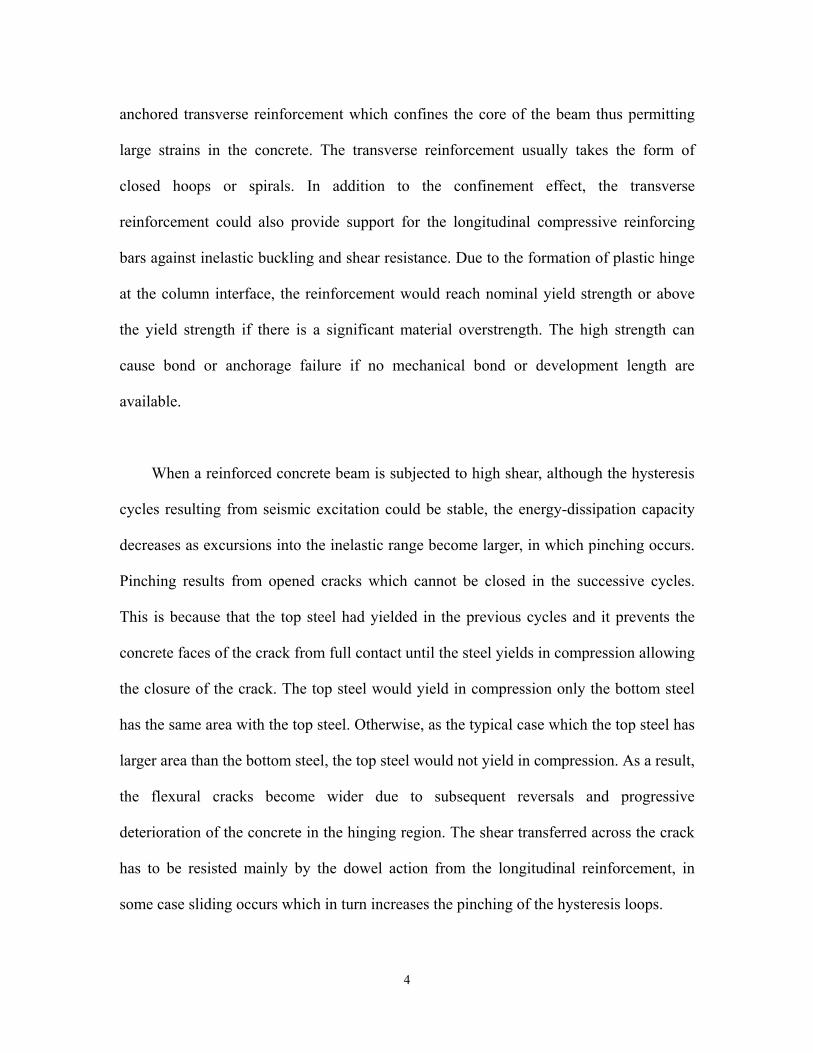
2.1 STUDY BUILDING DESCRIPTION
The study building is a regular five-story building; four bays in one direction and
three bays in the other direction. The special moment frames or the special segment
frames in the longitudinal direction are analyzed as shown in Figure 2-1. Figure 2-2
shows the profile view of RC-SMRF while Figure 2-3 shows the profile view of RC-SSF.
20
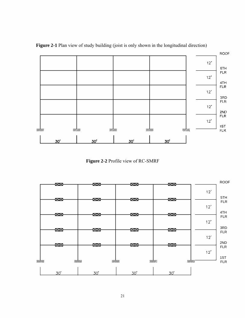
Figure 2-1 Plan view of study building (joist is only shown in the longitudinal direction)
Figure 2-2 Profile view of RC-SMRF
ROOF
5TH FLR
4TH FLR
3RD FLR
2ND FLR
1ST FLR
21

Figure 2-3 Profile view of RC-SSF
2.2 MASS AND GRAVITY LOADING DEFINITIONS Dead Load
Floor Slab =53 psf Plus beam weight =53×1.1=58.3 psf
Ceiling/Flooring =3 psf Mechanical/Electrical =7 psf Partitions =20 psf Roofing =7 psf
This gives the following dead loads: For typical floor (for weight calculations) =58.3+3+7+20 =88.3 psf For roof =58.3+3+7+7 =75.3 psf Live Load
Typical Floor =50 psf Roof =20 psf Building envelope =124’×94’ Floor slab envelope (for dead load calculations) =122’×92’ Floor slab envelope (for live load calculations) =120’×90
Dead Load due to Exterior Wall (full structure) Total Load =0.025× (5’×12’)×2× (124+94) =654 kips
22

1/10 goes to the ground and is not considered =65.4 kips 1/5 goes to the four floors =130.8 kips 1/10 goes to roof =65.4 kips
Dead Load due to Parpet on Roof (full structure) Total Load =0.025× (42/12) 2× × (124+94) =38.15 kips Live Load Reduction Factor
)1525.0(2A
R += (2.1)
2A = two times the tributary area for beam; four times the tributary area for column For +M 30’×20’ R=0.85 ⇒ −M 60’×20’ R=0.7 ⇒ In this study, using R=0.85 for all elements. All the proportion is according to the interior frame. Beam Load Calculations The beams take the dead and live loads of a 10 ft. tributary.
Floor 2 3 4 5 From slab (dead load) = 0.0883×1 0 =0.883 kip/ft From slab (live load) = 0.05×10×0.85 =0.425 kip/ft D+L = 0.883+0.42 = 1.308 kip/ft ( ) 1W
Roof
23

From slab (dead load) = 0.0753×1 0 =0.753 kip/ft From slab (live load) = 0.02×10 =0.20 kip/ft D+L = 0.753+0.20 = 0.953 kip/ft ( ) 2W
Concentrated Loads at Columns of Interior Frame These loads are due to the transverse beams in the transverse direction.
Floor 2 3 4 5 Dead load (exterior column lines) = (16×10×0.0883)×2 =28.26 kips
Live load (exterior column lines) = (15×10×0.05×0.85)×2 =12.75 kips
D+L = 28.26+12.75 = 41.01 kips ( ) 1L
Dead load (interior column lines) = (30×10×0.0883)×2 =52.98 kips Live load (interior column lines) = (30×10×0.05×0.85)×2 =25.50 kips
D+L = 52.98+25.50 = 78.48 kips ( ) 2L
Roof
Dead load (exterior column lines) = (16×10×0.0753)×2 =24.1 kips Live load (exterior column lines) = (15×10×0.05)×2 =6 kips
D+L = 24.1+6= 30.1 kips ( ) 3L
Dead load (interior column lines) = (30×10×0.0753)×2 =45.18 kips
Live load (interior column lines) = (30×10×0.02)×2 =12 kips
D+L = 45.18+12 = 57.18 kips ( ) 4L
24

Summary Unfactored gravity loading:
1W = 1.308 kip/ft
2W = 0.953 kip/ft
1L = 41.01 kips
2L = 78.48 kips
3L = 30.1 kips
4L = 57.18 kips The distribution and location of unfactored gravity loadings are shown in Figure 2-4.
3L3L
1L
1L
1L
1L
1L
1L
1L
1L
4L
2L
2L
2L
2L
4L
2L
2L
2L
2L
4L
2L
2L
2L
2L
2W
1W
1W
1W
1W
2W
1W
1W
1W
1W
2W
1W
1W
1W
1W
2W
1W
1W
1W
1W
25

Figure 2-4 Gravity loading definition
Total Weight
Slab + Beam = (0.0883×4+0.0753)× (122’×92’) =4809.5 kips Exterior wall =654 kips Parapet =38.15 kips Columns = 20× (5×12’)× (2×2)×150pcf/1000 =720 kips
Total weight = 6221.65 kips
For Floor 2 3 4 5
xW = (0.0882)× (122×92)+130.8 =1221.88 kips Column weight for each floor = 720× (1/5) =144 kips
5432 xxxx WWWW === = 1221.88+144 =1365.88 kips
For Roof
RoofW
= (0.0753)× (122×92)+65.4+38.15+144/2(half column weight) =1020.72 kips Column weight for each floor = 720× (1/5) =144 kips UBC Load Combinations (UBC 97 Strength Design) In this study, four load combinations as per UBC section 1612.2 were adopted: 1.2D+1.0E+0.5L (UBC 12-5) 1.2D-1.0E+0.5L (UBC 12-5) 0.9D+1.0E (UBC 12-6) 0.9D-1.0E (UBC 12-6)
26

2.3 EQUIVALENT LATERAL STATIC FORCE PROCEDURE (UBC 1997) 2.3.1 UBC seismic force parameters
Seismic Zone 4, Z=0.4
Closet distance to seismic source 10km, Seismic Source Type = B, Near Source
Factor ,
≥
0.1=aN 0.1=vN
Seismic Importance Factor =1.0
Soil Profile Type = DS
, 64.064.0 == vv NC 44.044.0 == aa NC
, .60512 fthn =×= 43
)( nt hCT =
03.0=tC for reinforced concrete SMRF
.sec65.0)60(03.0 43==⇒ T
is neglected. vE
Reliability/Redundancy Factor 0.1=ρ , hvh EEEE =+= ρ
R=8.5 for both RC-SMRF and RC-SSF.
Note: R value for the STMF is 6.5 in UBC97; however, for the purpose of
comparison of the behavior of RC-SSF and RC-SMRF, the R value for RC-SSF was
decided to use the same value, 8.5, as the R value of RC-SMRF so that they were
subjected to the same design lateral loads.
for both RC-SMRF and RC-SSF 8.20 =Ω
27

.sec65.0.sec58.044.05.2
64.05.2
<=×
==a
vs C
CT , .sec116.02.0 == so TT
Seismic Dead Load = Total weight
Design Base Shear V:
WR
ICW
RTIC
VWR
IZN avv )5.2
()()8.0
( ≤=≤
WWW 129.0116.0038.0 ≤≤⇒ O.K.
kipsWVT 71.721)65.6221(116.0116.0 ===
For each frame, kipsVV T 43.1804
==
2.3.2 Distribution of seismic forces
In accordance with UBC section 1630.5, the concentrated force at top may be
considered as zero if T (=0.65 second in the study) is less than 0.7 second.
tF
Therefore the distributed forces are:
∑∑==
−=
−= n
ixx
xxn
iii
xxtx
hW
hW
hW
hWFVF
11
)043.180()( (UBC 30-15)
xF : equivalent inertia force at each level
tF : concentrated force at top
V : base shear
28

xW (or ) : the seismic weight of the structure at each level iW
(or ) : the height of each level from the ground level xh ih
The results are listed in Table 2-1.
Table 2-1 UBC design lateral forces
Level xh (ft.) xW (kips) xxhW (k-ft) ∑ xx
xx
hWhW
xF (kips)
Roof 60 1020.72 61243.2 0.272 49.08
5 48 1365.88 65562.24 0.291 52.51
4 36 1365.88 49171.68 0.218 39.33
3 24 1365.88 32781.12 0.146 26.34
2 12 1365.88 16390.56 0.073 13.17
2.4 DESIGN OF RC SPECIAL MOMENT FRAME
The design of RC-SMRF is in accordance with the provisions in chapter 21 of ACI
318-99 Building Code. Most design requirements have been discussed in Chapter 1 of
this report. The final design sections of beam and column (column-to-beam strength ratio
= 1.2) are shown in Figure 2-5; however, the transverse reinforcement (stirrups or hoops)
is not shown here.
The drift can be checked as per UBC 1630.9. As the period T is less than 0.7 seconds:
29

.18025.016.8371.15.87.07.0 inhinR SM =≤=××=Δ=Δ o.k.
Here, (1.371in.) is obtained from the static elastic analysis using the design seismic
force.
SΔ
2ND FLR 3RD FLR 4TH FLR 5TH FLR ROOF
1sA 4-#7 4-#8 4-#7 4-#6 4-#6
sA 3-#7 3-#7 4-#6 4-#6 4-#6
Figure 2-5 Beam and column sections of the study RC-SMRF
30

2.5 DESIGN OF RC SPECIAL SEGMENT FRAME
The design of RC-SSF was in accordance with the former research suggestions (Itani
and Goel, 1991; Basha anf Goel, 1994; Leelataviwat and Goel, 1998; Rai, Basha and
Goel, 1998) and the AISC Seismic Provision (AISC, 1997). Design procedure is depicted
as follows:
1) Special segment design criteria:
The size of X-diagonal members and chord members in the special segment are
selected based on the maximum vertical force resulting from 1.2D+1.0E+0.5L.
The shear contribution by X-diagonals is limited to 75% of the required shear
. reqV
Chords of the S.S. (Special Segment) are designed for remaining 25% of the
required shear which is resisted through the end plastic hinges.
X-diagonal members are interconnected at point of crossing.
X-diagonal members are flat bars with 5.2≤tb
Chord angle sections must have yFt
b 52≤
The length of the S.S. shall be between 0.1 and 0.5 times the span length (AISC
12.2). In this study, a length of 0.2 times the span length was used.
31
The length-to-depth ratio of any panel in the S.S. shall neither exceed 1.5 nor
be less than 0.67 (AISC 12.2)
The axial stress in the chord members shall not exceed 0.45 times
gy AFφ ( 9.0=φ ).
Design of RC-SSF could be quite sensitive to the strength of the elements in a
S.S. which in turn results in oversizing of the elements outside the S.S. For
optimizing the chord members, built-up sections composing of double angles
and plates were used in this study.
2) Design of concrete elements outside the S.S.:
Determine the amplified vertical shear for design of members outside the S.S. oV
αξξ
sin)3.0(95.0
(4 )xcxyx
o
chco PP
LM
V ++= (2.2)
Where,
cξ is the overstrength of the opening (not including the diagonal members) (Basha,
1994):
ch
chs
sc
c M
ML
LLEI )1(])[6( 2 ηδη
ξ−+
−
= (2.3)
δ is the story drift, assuming 0.03.
η is the strain hardening factor (0.1. in this study)
32

E=29000 ksi
cI is the moment inertia of the chord member
L is the beam span length
oL is the length of S.S.
sL is the distance between plastic hinges of S.S., here assuming os LL 95.0≅
chM is the plastic moment of chord member
xξ is the overstrength of the diagonal member, using 1.1 for A572 Grade 50 and 1.5 for
A36 (AISC, 1997)
xyP is the yield force of the diagonal members
xcP is the buckling force of the diagonal members
α is the angle between the diagonal member and the chord member
Design the concrete beam using the moment resulting from the gravity load and the
amplified shear force in the S.S.
The design negative moment gc
o MdLVM +−=− )22
(max
cd is the column depth
The design positive moment gc
o MdLVM −−=+ )22
(max
The design then is in accordance with the ACI 318-99 approach.
Plastic design procedure for concrete column
A predictable global yield mechanism is more desirable so that the damage could be
33

limited in some portion of the frame. For the proposed RC-SSF, all the inelastic
deformations are intended to limited in the special segment in the form of buckling and
yielding of diagonal members and the form of plastic hinges formation in chord members.
Since plastic hinges in the column bases are inevitable during a major earthquake, the
desirable global yield mechanism of the RC-SSF is the yielding (due to the induced shear
force in the middle of the special segment) plus the plastic hinges in the column bases.
As discussed earlier, the distribution of internal forces in the column could be quite
different from the prediction of an elastic analysis while experiencing an earthquake.
Therefore, an alternative design procedure in which the global yield mechanism is
predestinated was used to design the columns of the RC-SSF. This procedure has been
developed on the plastic design basis for design of steel moment frames by Leelataviwat
et al (Leelataviwat, Goel and Stojadinović, 1998). The only distinction for a RC-SSF is
that the intended inelastic deformation locations are in the special segments rather than
the plastic hinges at beam ends.
In order to ensure that the columns remain elastic (except for the column bases) even
the global yield mechanism has formed, the amplified shear forces should be used in
the design. A free body diagram of an exterior column of the frame is shown in Figure
2-6. As can be seen in Figure 2-6, the overturning moment results from the
earthquake-induced inertial lateral forces should be the same with the resisting moment
results from the gravity loadings, amplified shear forces, and plastic moment of the
column base. The earthquake-induced lateral forces can be assumed to have the same
inverted triangular distribution along the height of the frame as specified in the UBC
oV
34

code.
The distributed lateral forces can be expressed as the function of updated base
shear (which related to the plastic analysis rather than the elastic analysis) for one column
by:
iF
∑=
−= 5
1
)(
jjj
iitci
hW
hWFVF (2.4)
1F
2F
3F
4F
5F
pcM
1GM
2L
2GM
3GM
4GM
5GM
1oV
2oV
3oV
4oV
5oV
ih
)(hMC
5GP
1oV
2oV
3oV
4oV
5oV5EP
4GP
3GP
2GP
1GP
4EP
3EP
2EP
1EP
35
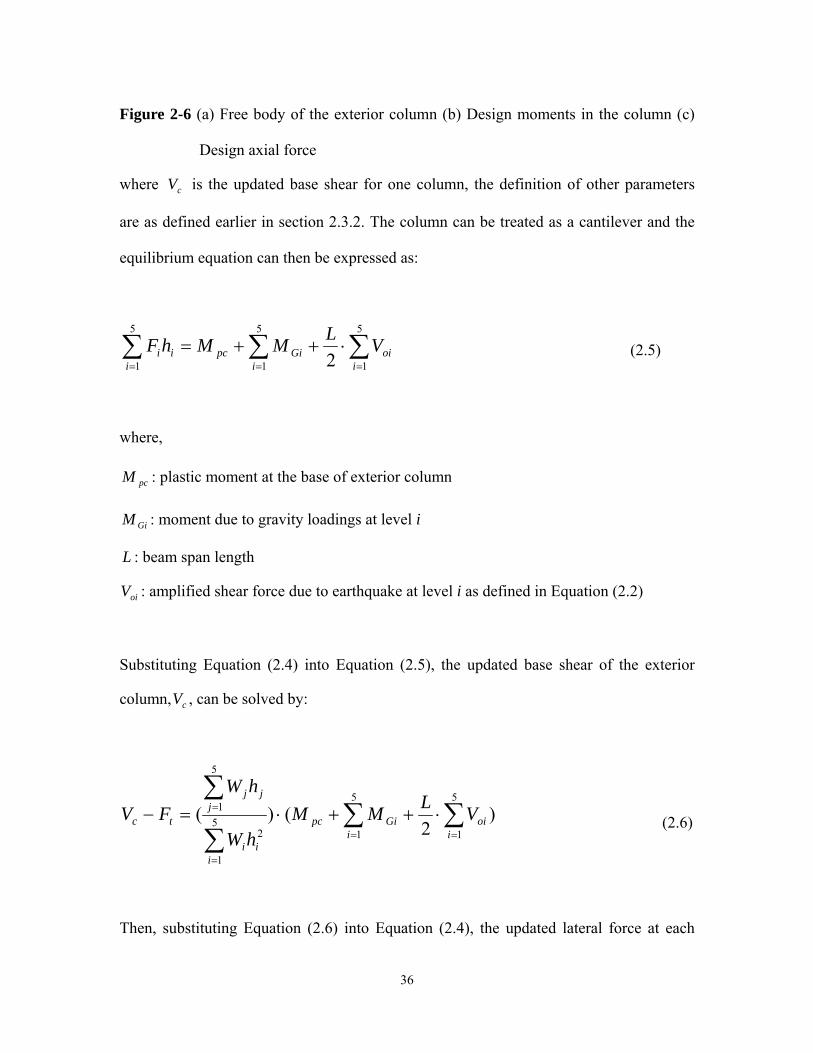
Figure 2-6 (a) Free body of the exterior column (b) Design moments in the column (c)
Design axial force
where is the updated base shear for one column, the definition of other parameters
are as defined earlier in section 2.3.2. The column can be treated as a cantilever and the
equilibrium equation can then be expressed as:
cV
∑∑∑===
⋅++=5
1
5
1
5
1 2 ioi
iGipc
iii VLMMhF (2.5)
where,
pcM : plastic moment at the base of exterior column
GiM : moment due to gravity loadings at level i
L : beam span length
oiV : amplified shear force due to earthquake at level i as defined in Equation (2.2)
Substituting Equation (2.4) into Equation (2.5), the updated base shear of the exterior
column, , can be solved by: cV
)2
()(5
1
5
15
1
2
5
1 ∑∑∑
∑==
=
= ⋅++⋅=−i
oii
Gipc
iii
jjj
tc VLMMhW
hWFV (2.6)
Then, substituting Equation (2.6) into Equation (2.4), the updated lateral force at each
36

level i is:
)2
()(5
1
5
15
1
2∑∑
∑ ==
=
⋅++⋅=i
oii
Gipc
iii
iii VLMM
hW
hWF (2.7)
Once the lateral seismic forces have been determined, the design moments at
top and bottom column of each level can be easily obtained by static equilibrium.
)(hM c
The design axial force for the column at each level is the resultant of the axial force
due to gravity loading and the axial force due to amplified shear force which are depicted
in Figure 2-6 (c). Therefore, the design axial force in the column at level i can be
expressed as:
∑=
+=5
ijojGii VPP (2.8)
where,
iP : design axial force at level i
GiP : axial force due to gravity loadings acting at level i
ojV : amplified shear force at level j due to earthquake
After the design axial force and moment at each level are determined, the column
can be designed in accordance with the procedure in the ACI 318 Building Code. The
37

design approach for interior columns is similar to the approach for exterior columns.
However, as can be seen in Figure 2-7 (a), the moments induced by gravity loads at both
sides of the column cancel out. The moments due to amplified seismic shear forces will
be doubled. On the other hand, the earthquake-induced axial forces at both sides of the
interior column cancel out (ideal condition) and the design axial forces are only from the
gravity loads (Figure 2-7(c)).
1oV
2oV
3oV
4oV
5oV
1F
2F
3F
4F
5F
1oV
2oV
3oV
4oV
5oV
pcM
2L
)(hMC
1oV
2oV
3oV
4oV
5oV
1oV
2oV
3oV
4oV
5oV5GP
4GP
3GP
2GP
1GP
Figure 2-7 (a) Free body of the interior column (b) Design moments in the column (c)
Design axial force
The plastic moment at the base of the column could be decided by using the
38

expected material strength with the design axial force. However, a conservative
alternative is to use the design strength which results from the nominal moment ( )
determined in accordance with the code requirements multiplied by the strength reduction
factor (
nM
φ ). This alternative can lead to a stronger column. Generally, the design of
column starts with a trial section, then the plastic moment (or design strength) is
calculated. The corresponding design values can be determined through the approach
mentioned above. If the column section is not on the safe side after investigating the
axial-moment interaction curve, use another column section and repeat the approach until
an appropriate column section is obtained.
The final design results of the RC-SSF are shown in Figure 2-8 and Figure 2-9.
39

Figure 2-8 Special segment sections of the study RC-SSF
40

2ND FLR 3RD FLR 4TH FLR 5TH FLR ROOF
1sA 6-#8 6-#8 8-#6 8-#6 4-#7
sA 6-#6 6-#6 6-#5 4-#6 4-#6
Figure 2-9 Beam and column sections of the study RC-SSF
41

CHAPTER 3
STATIC PUSH-OVER ANALYSIS AND NONLINEAR DYNAMIC ANALYSIS
3.1 NONLINEAR ANALYSES OF THE STUDY BUILDINGS
In order to evaluate the behavior of the study buildings under a major earthquake,
nonlinear analyses including both static push-over analyses and dynamic analyses were
performed to compare the behavior of the RC-SMRF and the proposed RC-SSF. The
RC-SSF was analyzed by the SNAP-2DX (Rai, Goel, and Firmansjah, 1996) which has
an excellent ability to model the steel elements, especially the brace member. A
pre-analysis showed that the SNAP-2DX program cannot model reinforced concrete very
well therefore the RC-SMRF was analyzed by using the PERFORM-2D program which
can model the reinforced concrete element quite well. It is noted that some analysis
discrepancy may result due to different programs used. The inelastic static analysis was
performed till the roof drift of either frame has reach a target roof drift of 3%. Several
different types of earthquake time-history were used to analyze the study buildings.
3.2 MODELING APPROACH OF FIVE STORY RC-SMRF AND RC-SSF
3.2.1 RC-SMRF
1. An interior moment frame with four bays was used in this study. All columns in this
model have the same flexural rigidity which is equal to . All of the beams gc IE7.0
42

with an effective slab width of 80 inches have the same flexural rigidity which is
equal to gc IE35.0 .
2. Expected material strength for reinforcing steel tensile and yield strength used in this
model is 1.25 times of the nominal strength of reinforcing steel in beams and columns
as per Table 6-4 in FEMA 356; the concrete compressive strength was decided not to
be translated to the expected strength but remain 4 ksi as used in design.
3. Beams were modeled as a compound member which consists of a rigid link from the
center of column to the face of beam member, a “moment hinge” (the term
PERFORM-2D uses for the plastic hinge element) with a trilinear moment-curvature
backbone curve, and an elastic element in the middle. The tributary length of plastic
hinge was chosen as 0.75 times the effective depth of the beam. Rigid links and
moment hinges are at both ends of the compound beam member. In static push-over
analysis, no strength degradation was modeled in the trilinear curve. In the non-linear
dynamic analysis, hysteretic parameters for accounting for the strength degradation,
stiffness deterioration, and pinching effect were modeled.
4. Columns were modeled as a compound member which consists of a rigid link from
the center of beams to the face of beam member, a moment hinge with an axial
force—moment interaction yielding face, elastic-perfectly-plastic moment—curvature
and force—displacement relationship for the hinge. The tributary length of plastic
hinge was chosen as 0.75 time of the effective depth of the column. Rigid links and
43

moment hinges are at both ends of the compound column member. In the nonlinear
dynamic analysis, stiffness deterioration was included. Joint deformation was not
included in the analyses.
5. The beam strength was calculated according to ACI 318-99 to allow for the slab in
compression and tensile force contribution of slab reinforcing bars within the
effective flange width.
6. Factored gravity loads were applied to beams as distributed load and columns as
concentrated loads. For the static push-over analysis, a triangular distributed lateral
force pattern assuming to the first-mode predominant response was used since this
building has only five stories. That is, higher modes effect was ignored in non-linear
static push-over analysis. A study conducted by Mwafy and Elnashai (2001)
concludes that there is only 4% difference in the results between triangular and
multimodal distribution load patterns for 8 to 12 story RC buildings.
7. The slab was assumed rigid so that the displacement of joints in the same floor level
would be identical.
8. For non-linear dynamic analysis, the masses were lumped at the joints.
9. In this model, all the various sources of damping were represented by viscous
damping. A damping ratio of 5% was adopted in this study.
44

10. During the analysis, the gravity load was applied first to the structure and the
nonlinear push-over analysis or nonlinear dynamic analysis was conducted in
succession.
3.2.2 RC-SSF
1. The previous research (Itani 1991; Basha 1994; Leelataviwat 1998) regarding the
special truss moment frame or truss moment frame with ductile Vierendeel segment
or seismic upgrading of steel moment frame by using ductile web openings has used
either equivalent one-bay model or 212 bay model instead of the whole frame.
However, to be more close to the actual behavior, a whole multi-bay model was
adopted to simulate the behavior of the study buildings.
2. The flexural rigidity of reinforced concrete beam and column members were the same
as used in RC-SMRF for conservatism. Expected material strength for reinforcing
steel tensile and yield strength used in this model is 1.25 times of the nominal
strength of reinforcing steel in beams and columns as per Table 6-4 in FEMA 356;
however, the concrete compressive strength was decided not to be translated to the
expected strength but remain 4 ksi as used in design.
3. As per the AISC Seismic Provisions for Structural Steel Buildings (AISC 1997), the
expected material yield strength for modeling the real strength of steel member such
45

as chord member, vertical member, and brace member were 1.5 times and 1.1 times
the nominal yield strength for A36 steel and A572/Grade 50 steel, respectively. A 10%
of strain-hardening ratio was used for the post-yield response.
4. The moment-curvature curve for concrete beam member in SNAP-2DX is a bi-linear
model curve. For non-linear dynamic analysis, hysteretic parameters have been
assigned to account for strength degradation, stiffness deterioration, and pinching
effect even though the beam would be expected elastic for RC-SSF.
5. RC columns were modeled by the beam-column element in the SNAP-2DX program.
6. A parametric study conducted by Itani and Goel (1994) suggested that a range of 0.25
L~ 0.5 L for length of the special segment should be generally satisfactory for the
STMF. A short special segment length and less number of X-panels would increase
the ductility demand in all the members in the special segment. However, for the
purpose of the study, a 0.2L for the special segment and two X-panels was adopted
even though a four X-panel special segment has been suggested by Itani (1991).
7. The chord member was modeled as a beam-column element with expected material
strength. Because of the relatively short length of the chord member and bending in
double curvature, high moment gradient would be induced in chords of the special
segment, resulting in large bending strains which in turn cause rapid and greater strain
hardening of the material. This phenomenon was also observed in the EBF systems by
Popov et al. A value of 10% strain hardening for chord member has been suggested
46

by Basha (1994) based on results of three tested specimens. Thus, the strain hardening
ratio of the beam-column chord member was 10%.
8. The brace member in the special segment was modeled using Jain’s hysteretic model
(Jain et al. 1978), which is capable of modeling the post-buckling strength and
stiffness as well as the elongation in the element. The model uses several straight-line
segments depending on several control parameters in compression, but it is bi-linear
in tension. In compression, the compressive strength reaches the buckling strength in
the former cycle. In subsequent cycles, the compressive strength reduces to the
post-buckling strength specified by a strength reduction factor. A strength reduction
factor of 0.3 has been found to correlate well with the results from experiments (Jain
et al. 1978). In tension, the element yields at the yielding strength of the element.
After the yield point, the load carrying capacity remains at the same level without
strain hardening. The intersection of the braces in one panel was only assigned two
degree of freedom, that is, vertical and horizontal displacement. The reason is due to
the observation from previous research conducted by Itani and Leelataviwat. The
results have shown that the intersection of braces welded to a small plate did not
rotate even though all the braces have experienced sever inelastic deformation.
9. In the previous research ((Itani 1991; Leelataviwat 1998), the vertical member in the
middle of the special segment has been designed and modeled as pure compressive
member which was only used to transfer the shear force. However, observations in
experimental studies have shown that the ends of vertical members experience
significant yielding. The actual deformation behavior can be show in Figure 3-1. As
47

can been seen, the vertical member would also bend in double curvature due to the
lateral drift of the floor. Hence, in this study, the vertical member was modeled as a
beam—column element as the chord member. A strain hardening ratio of 10% was
chosen. The reason is the same as the chord member.
10. A vertical rigid link was used as the interface of concrete beam and the special
segment. This rigid link was modeled as a beam—column element with very large
stiffness and strength.
11. The beam strength was calculated according to ACI 318-99 to allow for the slab in
compression and tensile force contribution of slab reinforcing bars within the
effective flange width.
12. All the former research (Itani 1991; Basha 1994; Leelataviwat 1998) has neglected
the gravity load when analyzing the buildings. However, gravity load could affect the
behavior of a SMRF. Lee et al. (1994) pointed out that, if the gravity load effect was
accounted for, excessive structural damage may occur in the lower floors of
multistory SMRF subjected to a strong earthquake. Therefore, gravity load was
included in the analyses. For some reason, the gravity load of the building can not be
applied on the beam as a distributed load, nor can it be applied at the end as fix-end
load in the SNAP-2DX program for a concrete type beam. Therefore, an alternative
method was used to apply the factored gravity load. First, an elastic analysis by
RISA-3D program was performed to obtain the internal moment and shear force in
the beams due to gravity load. Then, those internal forces and moments were applied
48

to beam and column ends as initial force load pattern allowed in the SNAP-2DX
program. Finally, the concentrated loads due to tributary gravity load were applied to
all columns as static load pattern. The lateral load or earthquake acceleration could be
added in succession. To justify this alternative, a RC-SMRF using this method for
applying gravity load on beams was compared with the same RC-SMRF analyzed by
RISA-3D program. A small amount of lateral load was applied to this building in both
of the two programs after gravity load was applied. Comparison of the results shows
quite similar internal forces at all member ends. Thus, this alternative was considered
acceptable for analysis of the RC-SSF.
13. The slab was assumed rigid so that the displacement of joints in the same floor level
would be identical.
14. For non-linear dynamic analysis, the masses were lumped at the joints.
15. In this model, all the various sources of damping were represented by viscous
damping. A damping ratio of 5% was adopted in this study.
49

γβ
θ θ
Figure 3-1 Deformation of chord member, brace member, and vertical member in the special segment with a length of Ls=0.2L and a two X-panels
50

3.3 EARTHQUAKE TIME-HISTORY FOR NONLINEAR DYNAMIC ANALYSES
3.3.1 Influence of near-fault ground motion
The near-fault ground motions have been one of the main issue since recent
earthquakes such as Northridge Earthquake (U.S., 1994), Kobe Earthquake (Japan, 1995),
and Chi-Chi Earthquake (Taiwan, 1999) have led to destructive damage of structures.
After these events, the influence of near-fault effect on structures has attracted attention
from researchers and practicing engineers.
For a long time, the peak ground acceleration has been the parameter most
frequently associated with severity of ground motion. However, it has generally been
recognized that this parameter is not enough to accurately describe the complex
earthquake characteristics (Kramer, 1996). Other parameters such as frequency content,
duration, velocity, and displacement can have profound effects on the structural response
than the peak ground acceleration, particularly in the inelastic range. A large peak
acceleration may be associated with a short duration pulse of high frequency which is out
of the range of the natural frequencies of most structures. Therefore, most of the pulse is
absorbed by the inertia of the structures with little deformation. On the contrary, a
moderate acceleration with a long duration pulse can result in significant deformation of
the structure because the area under the acceleration pulse that represents the incremental
velocity is quite large. When the incremental velocity is multiplied by the mass represents
the impulse. This impulse can be generated in the near-fault region which is the result of
shear waves moving in the same propagating direction of the fault rupture, thus
51
overlapping the pulses which in turn cause the Doppler-like effect. This overlapping will
produce strong long duration fling pulse at the sites toward which the fault ruptures (Bolt,
1996; Kramer, 1996).
The near-fault impulse type ground motion can be very damaging to structures if the
structure can not dissipate the sudden burst of energy. Most buildings designed by current
design codes might not have enough time for cyclic vibration to efficiently utilize
structural damping. Study performed by Naeim (1995) revealed that damping has little
effect in dissipating the energy when a moment frame was struck by a near-fault ground
motion, and the large portion of the energy has to be dissipated through hysteretic energy,
that is, the structural damage. Furthermore, the fling pulse tends to concentrate the
inelastic behavior in the lower floors of buildings because the upper floors do not have
sufficient time to response. Liao et al (Liao, Koh, and Wan, 2001) analyzed two
RC-SMRFs subjected to the 1999 Chi-Chi Earthquake and found that story drifts in the
lower floors are much larger than the upper floors (For a 5-story RC-SMRF, the
maximum story drift was in the second floor; for a 12-story RC-SMRF. The maximum
story drift was in the forth floor). Meanwhile, the ductility demand and the induced base
shear are also larger than that due to far-field ground motions.
Therefore, to evaluate the performance of the RC-SMRF and the proposed RC-SSF,
two near-field records were chosen including the Sylmar record (1994 Northridge
Earthquake) and the TCU068-N record (1999 Chi-Chi Earthquake). Another time-history
record is the El Centro record, which was chosen because it is a classic base excitation
and contains a broad frequency. All these data was obtained from the PEER strong
52

motion database. It should be noted that, however, the study frames were not specifically
designed for near-fault site (see Section 2.3.1).
The acceleration, velocity, and displacement time-history of the three selected
records are shown in Figure 3-2, Figure 3-2, and Figure 3-4. The peak ground motion
parameters are listed in Table 3-1.
Table 3-1 Strong ground motion parameters
PGA (g) PGV (in/sec) PGD (in)
El Centro 0.313 11.73 5.24
Sylmar 0.843 51.02 12.87
Chi-Chi 0.462 103.58 169.29
As can be seen, the PGV and PGD of Chi-Chi record are much larger than those of
Sylmar record although the PGA of Chi-Chi record is smaller that the Sylmar record. The
Chi-Chi record of this study is from a station at a distance of 0.49km from the fault.
Hundreds of buildings collapsed in that event. The velocity or displacement pulses of the
Chi-Chi Earthquake have quite long duration which in turn causes large potential damage
in structures.
53

0 10 20 30Time (sec)
40
-0.8
-0.3
0.3
0.8
-1.0
-0.5
0.0
0.5
1.0
Acce
lera
tion
(g)
0 10 20 30Time (sec)
40
-0.8
-0.3
0.3
0.8
-1.0
-0.5
0.0
0.5
1.0
Acce
lera
tion
(g)
0 20 40 60 80Time (sec)
100
-0.8
-0.3
0.3
0.8
-1.0
-0.5
0.0
0.5
1.0
Acce
lera
tion
(g)
Figure 3-2 Three selected acceleration time-history in the study
54

0 10 20 30 4Time (sec)
0
-75.0
-25.0
25.0
75.0
-100.0
-50.0
0.0
50.0
100.0
Velo
city
(in/
sec)
5 15 25 350 10 20 30 4Time (sec)
0
-75.0
-25.0
25.0
75.0
-100.0
-50.0
0.0
50.0
100.0
Velo
city
(in/
sec)
0 20 40 60 80Time (sec)
100
-75.0
-25.0
25.0
75.0
-100.0
-50.0
0.0
50.0
100.0
Velo
city
(in/
sec)
Figure 3-3 Three selected velocity time-history in the study
55

El Centro
0 10 20 30 4Time (sec)
0
-150
-50
50
150
-200
-100
0
100
200
Dis
plac
emen
t (in
)
5 15 25 350 10 20 30 40Time (sec)
-150
-50
50
150
-200
-100
0
100
200
Dis
plac
emen
t (in
)
0 20 40 60 80Time (sec)
100
-150
-50
50
150
-200
-100
0
100
200
Dis
plac
emen
t (in
)
Figure 3-4 Three selected displacement time-history in the study
56

3.3.2 Seismic hazards for evaluation of the study buildings
In order to evalute the seismic behavior and performance of the RC-SMRF and the
proposed RC-SSF, proper seismic hazards must be selected. According to the FEMA 356
(FEMA, 2000), “ Seismic hazard due to ground shaking shall be based on the location of
the building with respect to causative faults, the regional and site-specific geologic
characteristics, and a selected Earthquake Hazard Level”. Based on these criteria, three
steps have been performed to obtain the appropriate seismic hazards:
1. Selection of Earthquake Hazard Level
Two hazard levels were chosen in this study. The first one is the Basic Safety
Earthquake-1 (BSE-1), which is the lesser of the ground shaking for a 10%/50 year
earthquake (i.e. 474 year mean recurrence interval) or two-thirds of the BSE-2 at a
site; the second one is the Basic Safety Earthquake-2 (BSE-2), which is the ground
shaking for a 2%/50 year earthquake at a site (i.e. 2475 year mean recurrence
interval). The latter is also known as the Maximum Considered Earthquake (MCE). In
the 1997 UBC or earlier NEHRP Provisions, the design ground motions are based on
a 90 percent probability of not being exceeded in 50 years. However, it is recognized
that larger ground motions are possible and they could occur at any time. On the other
hand, a structure designed in accordance with the modern design codes always has
some “seismic margin”. The “seismic margin” in a structure results from the
conservatism in the actual design process. This margin provides a level of protection
against larger, less probable earthquakes. A factor of 3/2 has been estimated for this
margin; that is, the structures designed by modern codes are in fact 1.5 times stronger
57

than the required strength. (FEMA 369, 2001)
Meanwhile, U.S. Geological Survey (USGS) seismic hazard maps indicate that the 2
percent probability of exceedance in 50 years earthquake (defined as Maximum
Considered Earthquake parameters are about 1.5 times the 10 percent probability of
exceedance in 50 years earthquake parameters in costal California and probably
more than 1.5 times in other areas (FEMA 369, 2001). Therefore, the Maximum
Considered Earthquake parameters can be used to evaluate the possibility of collapse
of a structure. In other words, if a structure experiences a level of ground motion 1.5
times the design level, the structure should have a low likelihood of collapse.
2. Selection of the location
The study buildings were assumed located in Los Angels City which is close to one
segment of the San Andreas Fault that caused the Northridge Earthquake in 1994. The
design response acceleration parameter of BSE-1 and BSE-2 can be found in the
USGS web site (http://eqint.cr.usgs.gov/eq/html/lookup.shtml). The corresponding
parameters are shown in Table 3-2. These parameters were obtained from the USGS
probabilistic maps which are updated once some new earthquakes occur. Meanwhile,
parameters are for specific sites rather than a whole seismic zone. Consequently, these
parameters are more realistic to evaluate the study buildings.
58

Table 3-2 Design response acceleration parameters for buildings located in
Los Angels City
10% PE in 50 yr 2% PE in 50 yr
sS (g) 1.121 1.688
lS (g) 0.381 0.667
3. Constructing the site-specific acceleration response spectrum for different hazard
levels
The acceleration response spectrum for evaluation of the study buildings can be
constructed in accordance with the procedures in FEMA 356 or FEMA 368 (FEMA,
2001). These spectra are shown in Figure 3-5 for BSE-1 and BSE-2, respectively.
Note that when designing a new building as per the procedure in NEHRP Provisions
(FEMA 368, 2001), the design spectrum is the same as that in FEMA 356. However,
the design spectral acceleration in NEHRP 2000 is two-thirds of the spectral
acceleration. For the study buildings, the fundamental period T is 0.65 seconds. By
investigating the 2%/50 yr earthquake response spectrum, the design acceleration is
equal to 1.538g×2/3 = 1.03g. Meanwhile, the design acceleration in accordance with
the UBC 97 for the study buildings is equal to 0.64/T = 0.64/0.65 1.0g which is
almost identical to 1.03g.
≅
59

0.2 0.6 1.0 1.4 1.80.0 0.4 0.8 1.2 1.6 2.0Period, T(sec)
0.2
0.6
1.0
1.4
1.8
0.0
0.4
0.8
1.2
1.6
2.0
Spec
tral A
ccel
erat
ion
(g)
0.2
0.6
1.0
1.4
1.8
0.0
0.4
0.8
1.2
1.6
2.0
0.2 0.6 1.0 1.4 1.80.0 0.4 0.8 1.2 1.6 2.0Period, T(sec)
0.2
0.6
1.0
1.4
1.8
0.0
0.4
0.8
1.2
1.6
2.0
Spec
tral A
ccel
erat
ion
(g)
0.2
0.6
1.0
1.4
1.8
0.0
0.4
0.8
1.2
1.6
2.0
Figure 3-5 Response spectra for BSE-1 and BSE-2
60

3.3.3 Earthquake records scaling procedure
Many procedures have been proposed for scaling earthquake records to represent a
design level earthquake. It has been recognized that the most critical acceleration can lead
to damage in a structure is the acceleration with the frequency close to the natural
frequencies of a structure rather than the peak ground acceleration. Also, the natural
period of a structure could gradually change during an earthquake. Therefore, in this
study, the scaling procedure was performed by scaling the pseudo acceleration spectrum
(obtained from the PEER Strong Motion Database, 5%damping) of an earthquake record
to the design level response spectrum and the maximum considered earthquake response
spectrum so that the accelerations in the vicinity of the fundamental period will be
approximately identical. This approach is depicted in Figure 3-6, Figure 3-7, and Figure
3-8. Note that only the design level response spectrum (i.e. 10%/50 yr earthquake) was
studied for Chi-Chi Earthquake since it has the essence of very near-field effect with
large and long duration velocity pulses which could have resulted in severe damage in
structures. It should be reiterated that, both the RC-SMRF and RC-SSF designed in this
study were based on 10% in 50 year hazard and no near-fault effect was considered
during the design. Therefore, very severe damage is expected when them subject to 2% in
50 year events or near fault event (such as the Chi-Chi ground motion used in this study,
which was recorded by a station only 0.49 km to the fault).
61
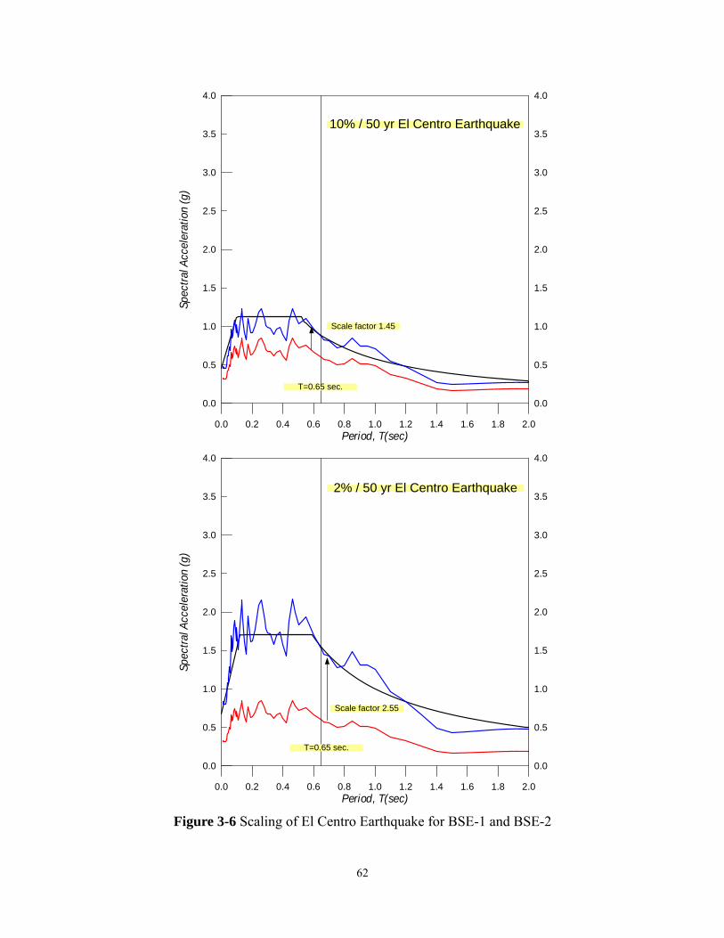
0.2 0.6 1.0 1.4 1.80.0 0.4 0.8 1.2 1.6 2.0Period, T(sec)
0.5
1.5
2.5
3.5
0.0
1.0
2.0
3.0
4.0
Spec
tral A
ccel
erat
ion
(g)
0.5
1.5
2.5
3.5
0.0
1.0
2.0
3.0
4.0
T=0.65 sec.
Scale factor 1.45
10% / 50 yr El Centro Earthquake
Scale factor 2.55
0.2 0.6 1.0 1.4 1.80.0 0.4 0.8 1.2 1.6 2.0Period, T(sec)
0.5
1.5
2.5
3.5
0.0
1.0
2.0
3.0
4.0
Spec
tral A
ccel
erat
ion
(g)
0.5
1.5
2.5
3.5
0.0
1.0
2.0
3.0
4.0
T=0.65 sec.
2% / 50 yr El Centro Earthquake
Figure 3-6 Scaling of El Centro Earthquake for BSE-1 and BSE-2
62

Scale factor 1/1.45
10% / 50 yr Sylmar Earthquake
0.2 0.6 1.0 1.4 1.80.0 0.4 0.8 1.2 1.6 2.0Period, T(sec)
0.5
1.5
2.5
3.5
0.0
1.0
2.0
3.0
4.0
Spec
tral A
ccel
erat
ion
(g)
0.5
1.5
2.5
3.5
0.0
1.0
2.0
3.0
4.0
T=0.65 sec.
Scale factor 1.15
2% / 50 yr Sylmar Earthquake
0.2 0.6 1.0 1.4 1.80.0 0.4 0.8 1.2 1.6 2.0Period, T(sec)
0.5
1.5
2.5
3.5
0.0
1.0
2.0
3.0
4.0
Spec
tral A
ccel
erat
ion
(g)
0.5
1.5
2.5
3.5
0.0
1.0
2.0
3.0
4.0
T=0.65 sec.
Figure 3-7 Scaling of Sylmar Earthquake for BSE-1 and BSE-2
63

Scale factor 1.2
10% / 50 yr ChiChi Earthquake
0.2 0.6 1.0 1.4 1.80.0 0.4 0.8 1.2 1.6 2.0Period, T(sec)
0.5
1.5
2.5
3.5
0.0
1.0
2.0
3.0
4.0
Spec
tral A
ccel
erat
ion
(g)
0.5
1.5
2.5
3.5
0.0
1.0
2.0
3.0
4.0
T=0.65 sec.
Figure 3-8 Scaling of Chi Earthquake for BSE-1
64

CHAPTER 4
RESULTS OF INELASTIC PUSH-OVER AND DYNAMIC ANALYSES
4.1 INELASTIC PUSH-OVER ANALYSES
The push-over analyses were performed by pushing both the RC-SMRF and
RC-SSF up to 3% of roof drift. As can be seen in Figure 4-1, in addition to the plastic
hinges formed in the column bases of the RC-SMRF, plastic hinges also formed in the
columns of the third and fourth levels. No inelastic activities occurred in the upper levels.
On the contrary, Figure 4-2 shows that there was no plastic hinges developed in the
columns except for the column bases in the RC-SSF. Furthermore, special segments in
every level entered into inelastic range in the form of buckling and yielding of brace
members, developing plastic hinges in the chord members, and developing plastic hinges
in the vertical members. The RC-SSF has higher redundancy over the RC-SMRF since it
has several lateral-resisting subsystems to dissipate the earthquake-induced energy.
Figures 4-2 and 4-3 provide detail of this characteristic. As can be seen, when the lateral
forces gradually increased, brace members in all floors buckled in the early stage
followed by the yielding of brace members. Then, plastic hinges formed in the exterior
column bases, chord and vertical members of the special segments in all floors. After 1%
roof drift, the plastic hinges of the interior column bases developed. The plastic hinges
continued forming in the chord members up to about 1.5 roof drift; afterward the whole
frame entered strain-hardening stage. Note all the reinforced concrete beams remained
elastic at the end of push-over analysis. All the inelastic activities were confined in the
special segments except for the column bases.
65

Figure 4-4 compared these two systems and it can be shown that they have almost
identical ultimate strength and system overstrength. The initial global stiffness of RC-SSF
is slight lower than the stiffness of RC-SMRF because of the buckling and yielding of the
brace members in the early stage. Comparison of the story drifts in the push-over process
of these two systems was shown in Figure 4-5. When the roof drift increased, the inelastic
activities concentrated in the lower levels of the RC-SMRF while the inelastic activities
uniformly distributed throughout the height of the RC-SSF. The lower levels of the
RC-SMRF have larger interstory drifts than other upper levels, thus increasing the
possibility of collapse due to P-delta effect. The reason why the story drifts of the
RC-SSF are uniform is that the upper levels participate in energy-dissipation from the
beginning of the push-over analysis so that the special segments of each level can share
the energy. In fact, the first buckled brace members were in the highest level. On the
other hand, the upper levels of the RC-SMRF remained elastic at the end of the analysis.
It has to be addressed that the design of the most top level beams of the RC-SMRF were
governed by the minimum reinforcement ratio; that is, the strength of the beam has
reached the lower bound. It is unlikely to force the upper beams to yield earlier by
weaken the beam strength.
66

Fig. 4-1 Plastic hinges distribution of RC-SMRF at 3% roof drift
Fig. 4-2 Inelastic activities distribution and sequence of RC-SSF at 3% roof drift
(Numbers represent the sequence of the inelastic activities)
67

Fig. 4-3 Lateral force – roof drift curve and inelastic activities sequence of RC-SSF
68

0.5 1.5 2.50 1 2 3Roof Drift (%)
0
100
200
300
400
500
600
700B
ase
Shea
r (k
ips)
Fig. 4-4 Comparison of lateral force – roof drift curves between RC-SMRF and RC-SSF
69

Comparison of Interstory Drift between RC-SMRF and RC-SSF
RC-SMRF
RC-SSF
Comparison of Interstory Drift between RC-SMRF and RC-SSF
RC-SMRF
RC-SSF
Comparison of Interstory Drift between RC-SMRF and RC-SSF
RC-SMRF
RC-SSF
Fig. 4-5 Comparison of interstory drift changes between RC-SMRF and RC-SSF form
1% roof drift to 3% roof drift
70

4.2 INELASTIC DYNAMIC ANALYSES
4.2.1 10%/50 yr El Centro Earthquake (Design Level Earthquake)
As mentioned in Chapter 3, the study buildings were designed for the design level
earthquake which has a mean recurrence period of 475 years (10% in 50 year). According
to the current design philosophy, the plastic activities are intended to occur mainly in
beams rather than columns. However, as can be seen in Figure 4-6, many plastic hinges
still formed in the column ends of the RC frame. The reasons contribute to this behavior
have been discussed in Chapter 1. It is easy to perceive the contrast between the seismic
behavior of RC-SMRF and RC-SSF by comparing the results from nonlinear dynamic
analyses in Figures 4-6 and 4-7. The RC-SSF behaved well because: first, all the inelastic
activities were confined in the special segments except for the column bases. Second,
beam ends remained elastic during the earthquake. Third, the plastic rotation demand in
the column bases is considerably smaller than the demand in the column bases of the
RC-SMRF. This is not only due to a stronger column that resulted from the plastic design,
but due to the contribution of the special segment as a “ductile fuse”. Parametric study
has shown that even though the RC-SMRF has the same column sections as the RC-SSF,
the plastic rotation demand is still slightly larger than the demand in the RC-SSF.
Figure 4-8 shows the floor displacements time history while the interstory drifts of
each level are show in Figure 4-9. Apparently, for the RC-SSF, each level has almost
identical interstory drift during the entire earthquake. However, the interstory drifts are
slightly larger in the lower levels of the RC-SMRF. Roof displacement time-history and
the absolute maximum interstory drifts are shown in Figure 4-10 and 4-11.
71

Fig. 4-6 Distribution of damage in the RC-SMRF subjected to design level (10% 50 yr)
El Centro Earthquake (Numbers represent the plastic rotation demand)
Fig. 4-7 Distribution of damage in the RC-SSF subjected to design level (10% 50 yr) El Centro Earthquake (Numbers represent the plastic rotation demand)
72

Fig. 4-8 Floor displacement time-history of RC-SMRF and RC-SSF subjected to design level (10% 50 yr) El Centro Earthquake
73

Fig. 4-9 Interstory drift time-history of RC-SMRF and RC-SSF subjected to design level (10% 50 yr) El Centro Earthquake
74

Fig. 4-10 Comparison of roof displacement between RC-SMRF and RC-SSF subjected
to design level (10% 50 yr) El Centro Earthquake
Comparison of Interstory Drift between RC-SMRF and RC-SSF
RC-SMRF
RC-SSF
Fig. 4-11 Comparison of interstory drift between RC-SMRF and RC-SSF subjected to
design level (10% 50 yr) El Centro Earthquake
75

4.2.2 2%/50 yr El Centro Earthquake (Maximum Considered Earthquake)
The maximum consider earthquake, which has a mean recurrence period of 2475
years, is used in the analysis to evaluate the capacity of the building for preventing
collapse although the frames were designed for earthquake event with a mean recurrence
period of 475 years. Therefore, more severe damage is expected.
The lower three levels of the RC-SMRF showed the potential story mechanism
which can be seen in Figure 4-12. Note that all the plastic hinges in one story did not
happen in the same instantaneous time. On the other hand, the performance of RC-SSF
was quite well and only minor inelastic activities occurred in some column ends (see
Figure 4-13). Floor displacement time histories for both frames were compared in Figure
4-14. Figure 4-15 shows that the interstory drifts in the lower levels (maximum about
3.5%) are larger than those in the upper levels, which in turn could cause the collapse in
the lower levels. Roof displacement time-history and the absolute maximum interstory
drifts are shown in Figure 4-16 and 4-17. Again, the RC-SSF exhibited very uniform
interstory drifts while the drift of the RC-SMRF was concentrated in the lower lever.
76

Fig. 4-12 Distribution of damage in the RC-SMRF subjected to maximum considered (2% 50 yr) El Centro Earthquake (Numbers represent the plastic rotation demand)
Fig. 4-13 Distribution of damage in the RC-SSF subjected to maximum considered (2%
50 yr) El CentroEarthquake (Numbers represent the plastic rotation demand)
77

Fig. 4-14 Floor displacement time-history of RC-SMRF and RC-SSF subjected to maximum considered (2% 50 yr) El Centro Earthquake
78

RC-SMRF2ND
3RD
4TH
5TH
ROOF
0 10 20 30 4
Time (sec)0
-5
-3
-1
1
3
5
-4
-2
0
2
4
Inte
rsto
rey
Drif
t(%
)
Fig. 4-15 Interstory drift time-history of RC-SMRF and RC-SSF subjected to maximum considered (2% 50 yr) El Centro Earthquake
79

Fig. 4-16 Comparison of roof displacement between RC-SMRF and RC-SSF subjected
to maximum considered (2% 50 yr) El Centro Earthquake
Comparison of Interstory Drift between RC-SMRF and RC-SSF
RC-SMRF
RC-SSF
Fig. 4-17 Comparison of interstory drift between RC-SMRF and RC-SSF subjected to
maximum considered (2% 50 yr) El Centro Earthquake
80
4.2.3 10%/50 yr Sylmar Earthquake (Design Level Earthquake)
As can be seen in Figure 4-18, although the plastic hinges spread in the RC-SMRF,
there was no potential story mechanism formed. The RC-SSF exhibited superior
performance with minor plastic activities in the columns. Figure 4-20 shows that the
RC-SMRF has significant residual interstory drifts, which primarily resulted from the
column hinging occurred in the RC-SMRF. On the other hand, as can be seen in Figures
4-21, 4-22, and 4-23, RC-SSF remained uniform interstory drift and small residual
displacement under a design level near-fault earthquake. The excellent performances such
as immediate reoccupancy, minor damage can be expected.
81

Fig. 4-18 Distribution of damage in the RC-SMRF subjected to design level (10% 50 yr)
Sylmar Earthquake (Numbers represent the plastic rotation demand)
Fig. 4-19 Distribution of damage in the RC-SSF subjected to design level (10% 50 yr)
Sylmar Earthquake (Numbers represent the plastic rotation demand)
82

Fig. 4-20 Floor displacement time-history of RC-SMRF and RC-SSF subjected to design level (10% 50 yr) Sylmar Earthquake
83
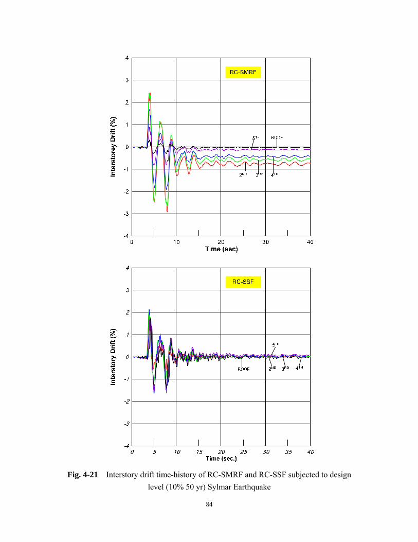
Fig. 4-21 Interstory drift time-history of RC-SMRF and RC-SSF subjected to design level (10% 50 yr) Sylmar Earthquake
84

Roo
fD
ispl
acem
ent
(in)
Fig. 4-22 Comparison of roof displacement between RC-SMRF and RC-SSF subjected
to design level (10% 50 yr) Sylmar Earthquake
Comparison of Interstory Drift between RC-SMRF and RC-SSF
RC-SMRF
RC-SSF
Fig. 4-23 Comparison of interstory drift between RC-SMRF and RC-SSF subjected to
design level (10% 50 yr) Sylmar Earthquake
85

4.2.4 2%/50 yr Sylmar Earthquake (Maximum Considered Earthquake)
Compare to the maximum considered El Centro Earthquake, it is evident that
maximum considered Sylmar Earthquake led to much higher plastic rotation demand,
especially in the lower levels which can be seen in Figure 4-24 and 4-25. The seismic
behavior of both frames can be investigated in Figure 4-26, 4-27, 4-28, and 4-29. Under
this earthquake, some potential story mechanism occurred in both frames. However, the
plastic rotation demands in the columns of the RC-SSF were relatively smaller than those
in the RC-SMRF. Note that the plastic rotation demands in the chord members and
vertical members of RC-SSF were very large which will cause those members to fail.
This large demand resulted because that this frame was designed for the 2% in 50 year
event. If the chord or the vertical members fail during the earthquake, it can jeopardize
the structure. This will be discussed later.
86

Fig. 4-24 Distribution of damage in the RC-SMRF subjected to maximum considered (2% 50 yr) Sylmar Earthquake (Numbers represent the plastic rotation demand). Note this frame was designed for 10% in to year event only.
Fig. 4-25 Distribution of damage in the RC-SSF subjected to maximum considered (2% 50 yr) Sylmar Earthquake (Numbers represent the plastic rotation demand). Note this frame was designed for 10% in to year event only. The larger plastic rotation demand would have led to failure.
87

Fig. 4-26 Floor displacement time-history of RC-SMRF and RC-SSF subjected to maximum considered (2% 50 yr) Sylmar Earthquake
88

Fig. 4-27 Interstory drift time-history of RC-SMRF and RC-SSF subjected to maximum considered (2% 50 yr) Sylmar Earthquake
89

Roo
fD
ispl
acem
ent
(in)
Fig. 4-28 Comparison of roof displacement between RC-SMRF and RC-SSF subjected
to maximum considered (2% 50 yr) Sylmar Earthquake
Comparison of Interstory Drift between RC-SMRF and RC-SSF
RC-SMRF
RC-SSF
Fig. 4-29 Comparison of interstory drift between RC-SMRF and RC-SSF subjected to
maximum considered (2% 50 yr) Sylmar Earthquake
90

4.2.5 10%/50 yr Chi-Chi Earthquake (Design Level Earthquake)
The record used in this study can be categorized as a very near-fault earthquake
since the distance from the station to the fault is only 0.49 km. Only the design level
earthquake was used in this study because the study frames were designed for 10% in 50
year event without near fault effect (Section 2.3.1). The 10% in 50 year Chi-Chi event is
expected cause severe damage. As mentioned in Chapter 3, the near-source impulse tends
to concentrate the inelastic behavior in the lower floors of buildings because the upper
floors do not have sufficient time to response. This behavior can be easily seen in Figure
4-30. In the RC-SMRF, the lower two levels have rather large plastic rotation demands,
which are about twice the demand under the maximum considered Sylmar Earthquake
(Figure 4-24). Note that in this study the peak ground displacement of the Chi-Chi record
is about 13 times that of the Sylmar record.
On the other hand, the plastic rotation demands in the upper level are even smaller
than the demands when subjected to the design level El Centro Earthquake (Figure 4-6).
As can be seen in Figures 4-32 and 4-33, the lower levels have significantly large
interstory drifts, which could have led to the collapse of the RC-SMRF. However, the
drifts of the upper levels were quite small. Apparently, the upper levels have no time for
response, because most of the input energy was absorbed only by the lower two levels.
This shows a unique characteristic of very near source earthquakes. Another concern
relates to the plastic rotation at the beam ends. As discussed in Chapter 1, plastic hinges
in the beam ends lead to yielding penetration into the beam-column joints. This in turn
could cause the slippage of the reinforcement and thus increase the lateral drift. Very
91

large plastic rotation demands can be found in the lower level beam ends (Figure 4-30),
which could be particularly detrimental to the beam-column joints of the RC-SMRF. Note
these values are used to illustrate the significant damaging of a near-fault event; a real
element cannot sustain such large rotation demand.
The RC-SSF could have performed better under the demands of this very near
source earthquake (Figure 4-31) if the steel elements can sustain the very large rotation
demand. No plastic hinge developed in the beam ends, which diminished the possibility
of failure in the beam-column joints. Furthermore, all columns remained elastic except
for the column bases, and the plastic rotation demands in the column base were
significantly smaller than those in the RC-SMRF. On the other hand, the large plastic
rotation demand in the column bases of the RC-SMRF resulted in very large drift in the
first floor, which might have been one of the primary causes of the collapse of many
reinforced concrete structures in the 1999 Chi-Chi event (See Figures 4-34, 4-35).
By accounting for the near-fault effect in the design process, the RC-SSF can be a
potential candidate for the high seismic zone especially in locations vulnerable to
near-field earthquakes, because of its unique energy-dissipation characteristic. The
inelastic activities of the RC-SSF can be uniformly spread to the special segment in each
level because all the special segments participate in the energy-dissipation process in the
early stages of the lateral deformation of the RC-SSF. Therefore, the inelastic activities
would not be concentrated only in the lower levels.
92
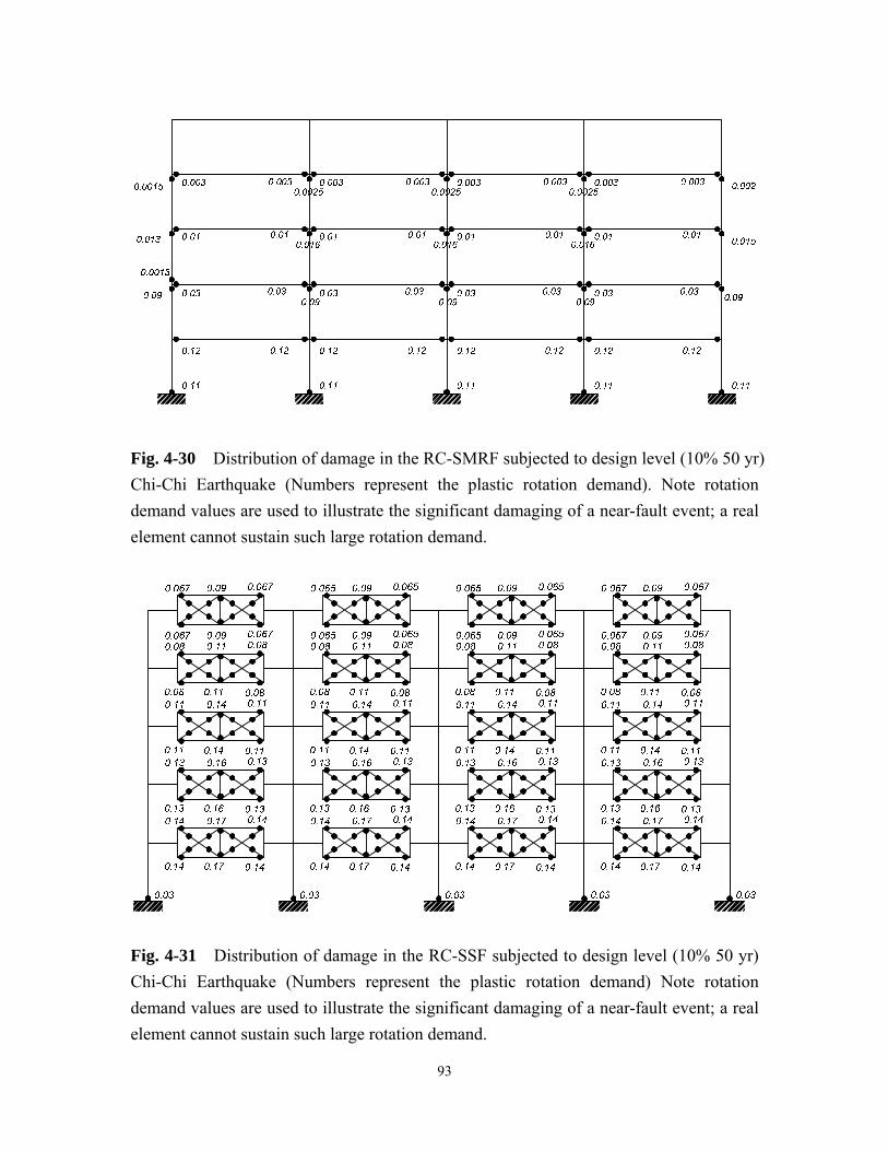
Fig. 4-30 Distribution of damage in the RC-SMRF subjected to design level (10% 50 yr) Chi-Chi Earthquake (Numbers represent the plastic rotation demand). Note rotation demand values are used to illustrate the significant damaging of a near-fault event; a real element cannot sustain such large rotation demand.
Fig. 4-31 Distribution of damage in the RC-SSF subjected to design level (10% 50 yr) Chi-Chi Earthquake (Numbers represent the plastic rotation demand) Note rotation demand values are used to illustrate the significant damaging of a near-fault event; a real element cannot sustain such large rotation demand.
93

Fig. 4-32 Comparison of roof displacement between RC-SMRF and RC-SSF subjected
to design level (10% 50 yr) Chi-Chi Earthquake
Comparison of Interstory Drift between RC-SMRF and RC-SSF
RC-SMRF
RC-SSF
Fig. 4-33 Comparison of interstory drift between RC-SMRF and RC-SSF subjected to
design level (10% 50 yr) Chi-Chi Earthquake
94

Fig. 4-34 Collapse of a reinforced concrete building during the Chi-Chi Earthquake. Note that the building collapsed due to the failure of the first floor columns without
failure in other floors (photographed by Shih-Ho Chao)
Fig. 4-35 Collapse of a reinforced concrete building during the Chi-Chi Earthquake due
to the failure of first floor columns (photographed by Shih-Ho Chao).
95

CHAPTER 5
DISCUSSION AND CONCLUSIONS
5.1 DISCUSSION
As mentioned in Chapter 3, the length of special segment and how many X-panels in
the special segment play a very important role in the behavior of the RC-SSF. A shorter
special segment would place higher ductility demand on each element in the segment. As
can be seen in the data from dynamic analysis of the 2%/50 year (i.e. return period 2475
year) Sylmar Earthquake, the required plastic hinge rotation is about 0.1 radian in the
chord member when experiencing an interstory drift of 3%. The Chi-Chi Earthquake also
requires a extreme high plastic rotation demand.
The mechanism in a special segment can be shown as Figure 3-1. When the story
moves laterally to a drift angleθ , plastic hinges are formed at the ends of the segment.
The segment rotates and results in a relative vertical displacement . The vertical
displacement could be expressed as the function of story drift, bay length, and the length
of special segment by assuming the interface of the special segment and reinforced beam
is rigid:
v
)( sLLv −=θ (5-1)
The approximate plastic rotation demand on the chord can be derived as follows:
96
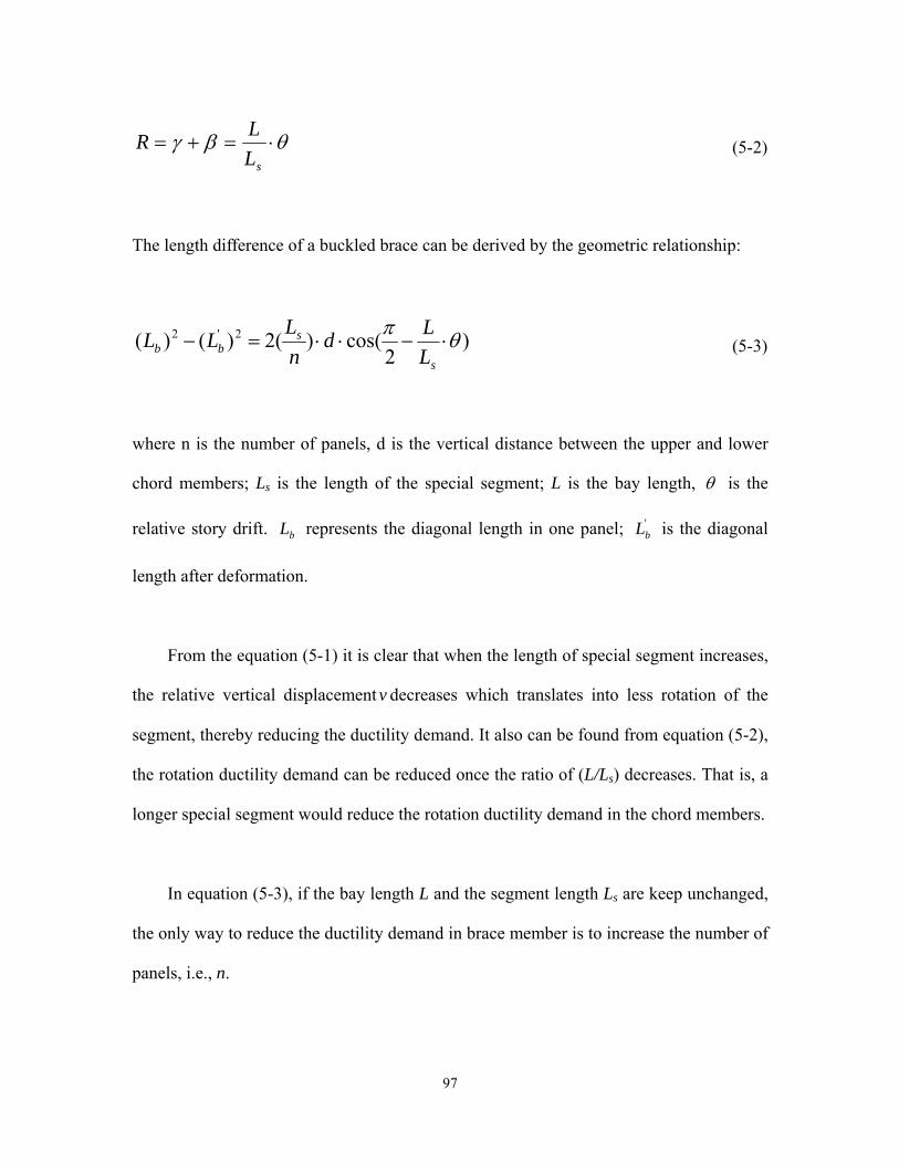
θβγ ⋅=+=sL
LR (5-2)
The length difference of a buckled brace can be derived by the geometric relationship:
)2
cos()(2)()( 2'2 θπ⋅−⋅⋅=−
s
sbb L
LdnLLL (5-3)
where n is the number of panels, d is the vertical distance between the upper and lower
chord members; Ls is the length of the special segment; L is the bay length, θ is the
relative story drift. represents the diagonal length in one panel; is the diagonal
length after deformation.
bL 'bL
From the equation (5-1) it is clear that when the length of special segment increases,
the relative vertical displacement v decreases which translates into less rotation of the
segment, thereby reducing the ductility demand. It also can be found from equation (5-2),
the rotation ductility demand can be reduced once the ratio of (L/Ls) decreases. That is, a
longer special segment would reduce the rotation ductility demand in the chord members.
In equation (5-3), if the bay length L and the segment length Ls are keep unchanged,
the only way to reduce the ductility demand in brace member is to increase the number of
panels, i.e., n.
97

A special segment with a length of 0.2L and two X-panels and a special segment
with a length 0.4L and four X-panels can be compared in Figure 3-1 and Figure 5-1. As
can be seen in Figure 5-1, the plastic rotational demand R1 (= 11 βγ + ), the vertical
displacement, and the elongated and shortened length are all diminished.
For a steel chord member, instability such as lateral torsional buckling or Flange
local buckling would occur before a higher plastic hinge rotation could be reached. Once
the instability occurs, the segment would fail and in turn jeopardize the whole building.
Thus, in order to assure the performance of the RC-SSF, the ductility demand in the
segment should be kept under some limitation. A parametric study conducted by Itani and
Goel (1992) suggested that a range of 0.25L~ 0.5L for length of the special segment
should be generally satisfactory and a four X-panels segment would be preferred, because
of the increased redundancy. By using 0.5L for the special segment in a RC-SSF located
in high seismic zone vulnerable to near-field earthquake could be very suitable. Moreover,
lower ductility demand in brace members would be expected by using four X-panels
instead of two X-panels.
Using a strong chord member or brace member to reduce the ductility demand
instead of using a longer special segment is not suggested. Since the design of member
outside the special segment is intended to be kept in the elastic range, the required
strength could be quite large when a small amount strength is increased in the elements of
special segment. Excess strength can be costly as other members of the frame are sized to
ensure that the special segment is the weakest portion of the frame.
98

With respect to the vertical member, its main function is to transfer shear force. The
strength of this member would not influence the strength of other members outside the
special segment. However, if it is too weak, it could fail. Therefore, a stronger section
could be used for the vertical member to prevent the failure.
1γ
1β
Fig. 5-1. Deformation of chord member, brace member, and vertical member in the special segment with a length of Ls=0.4L and a four X-panels
99

5.2 CONCLUSIONS
1. If the design parameters are the same, the proposed RC-Special Segment Frame
(RC-SSF) generally performs better than the conventional RC moment frame in many
aspects. Nonlinear dynamic analysis results show that, the majority of the input
energy would be absorbed by the special segment, thus keeping the beams and
column in the elastic range. Since inelastic behavior does not develop in the beam end,
the longitudinal reinforcement of beams will remain elastic, thus preventing yielding
from penetrating into the beam-column joints. Therefore, special reinforcement in the
beam ends and beam-column joints could be reduced and this would increase
constructability.
2. RC-SSF has relatively smaller and very uniform story drifts from lower level floors to
upper level floors, thus reducing the possibility of concentration of energy absorption
in any individual floor level (The design process used for the RC-SSF also
contributed to this result). The possibility of a story mechanism would also be
diminished. The unique seismic behavior of the RC-SSF is the consequence that the
special segments participate in the energy-dissipation process in the early stages of
the deformation of the RC-SSF. This occurs by means of uniform buckling and
yielding of the brace members in each floor.
3. The plastic hinges developed in the column base are inevitable for both RC-SMRF
and RC-SSF; however, the plastic rotation demand in the RC-SSF is generally smaller
in the column bases than in the RC-SMRF.
100

4. Repair after a major earthquake is easier in RC-SSF than in RC-SMRF because the
damage is generally confined only within the members in the special segments, which
locate at the midway of beams. On the other hand, damage in the RC-SMRF occurs in
the beam ends and the beam-column joints, where are usually not readily accessible
for repairing work due to presence of transverse beams and floor slab.
5. The adoption of special segments with 0.4L~0.5L and four X-diagonal panels is
recommended for high seismic zone locations that are vulnerable to the near-field
earthquakes. This may reduce the ductility demand in all the members of the special
segment. Further analyses and large-scale experiments should be performed to verify
the analyses and suggestions in this study.
101

BIBLIOGRAPHY
1. Abdel-Fattah, Bahjat; Wight, J. K. (1987), “Study of Moving Beam Plastic Hinging Zones for Earthquake-Resistant Design of R/C Buildings,” ACI Structural Journal (American Concrete Institute), v 84 n 1 Jan-Feb, 31-39
2. ACI committee 318 (1999), “Building Code Requirements for Reinforced Concrete
and Commentary (ACI318-99/ACI318R-99),” American Concrete Institute, Detroit. 3. Al-haddad, M. S., and Wight, J. K. (1988), “Relocating beam plastic hinging zones
for earthquake resistant design of reinforced concrete buildings,” ACI Structural Journal (American Concrete Institute), v 85 n 2 Mar-Apr, 123-133
4. American Institute of Steel Construction (1994), AISC-LRFD, “Load and Resistance
Factor Design,” Chicago, Illinois. 5. American Institute of Steel Construction (1997), “Seismic Provisions for Structural
Steel Building,” AISC, Chicago, Illinois. 6. American Institute of Steel Construction (2002), “Seismic Provisions for Structural
Steel Building (Draft),” AISC, Chicago, Illinois. 7. Basha, H., and Goel, S.C. (1994), “Seismic Resistant Truss Moment Frames with
Ductile Vierendeel Segment,” Report UMCEE 94-29, Dept. of Civ. & Env. Engrg., Univ. of Michigan, Ann Arbor, Michigan.
8. Bolt, B. A. (1996), “From earthquake acceleration to seismic displacement,” Wiley,
New York, 49pages. 9. Bruneau, M., Uang, C. -M. (1998), Whittaker, A., Ductile Design of Steel Structures,
McGraw-Hill. 10. Dooley, K. L, and Bracci, J. M. (2001), “Seismic Evaluation of Column-to-Beam
Strength Ratios in Reinforced Concrete Frames,” ACI Structural Journal (American Concrete Institute), v 98 n 6.
102

11. Ehsani, M. R., and Wight, J. K. (1985), “Effect of Transverse Beams and Slab on
Behavior of Reinforced Concrete Beam-to-Column Connections,” ACI Structural Journal (American Concrete Institute), v 82 n 2 Mar-Apr, 188-195
12. FEMA (2000), “Prestandard and Commentary for the Seismic Rehabilitation of
Buildings (FEMA 356),” Federal Emergency Management Agency, Washington, D. C.
13. French, C.W., and Moehle, J. P. (1991), “Effect of floor slab on behavior of
slab-beam-column connections,” Special Publication (SP-123), American Concrete Institute.
14. Goel, Subhash C.; Itani, A. (1994), “Seismic behaviour of open-web truss-moment
frames,” Journal of Structural Engineering, ASCE, 120 (6), 1763-1780. 15. Goel, S. C., and Itani, A. (1994), “Seismic Resistant Special Truss Moment Frames,”
Journal of Structural Engineering, ASCE, 120 (6), 1781-1797. 16. Goel, S. C., and Leelataviwat, S. (1998), “Seismic Design by Plastic Method,”
Engineering Structures, Elsevier Science, 20 (4-6), 465-471. 17. International Conference of Building Officials (1997), “Uniform Building Code,”
Volume 2, Whittier, Calif. 18. Itani, A. M., and Goel, S. C. (1991), “Earthquake Resistance of Open Web Framing
Systems,” Report UMCEE 91-21, Dept. of Civ. & Env. Engrg., Univ. of Michigan, Ann Arbor, Michigan.
19. Jain, A. K., Goel, S. C., and Hanson, R .D. (1978), “Hysteresis Model for Steel
Members Subjected to Cyclic Buckling and Cyclic End-Moments and Buckling—User’s Guide for EL9 and EL10 of Drain 2D,” Report UMCEE 78-6, Dept. of Civ. & Env. Engrg., Univ. of Michigan, Ann Arbor, Michigan.
20. Kramer, S. L. (1996), “Geotechnical earthquake engineering,” Prentice Hall, N. J.,
653 pages.
103

21. Lee, H.S. (1996), “Revised Rule for Concept of Strong-Column Weak-Girder
Design,” Journal of Structural Engineering, ASCE, 122 (4), 359-364. 22. Lee, S. Y., and Lee, D.G. (1994), “Effects of gravity load on seismic response of
multistory buildings,” Engineering Structures, v 16 n 6 Aug, 445-454 23. Leelataviwat, S., Goel, S. C., and Stojadinović, B. (1997), “Steel Moment Frames
with Ductile Girder Web Opening,” Engineering Journal, AISC, 34 (4), 115-125. 24. Leelataviwat, S. (1998), “Drift and yield mechanism based seismic design and
upgrading of steel moment frames,” Ph.D. Thesis, University of Michigan, Ann Arbor.
25. Leelataviwat, S., Goel, S. C., and Stojadinović, B. (1998), “Seismic design by plastic
method,” Engineering Structures, v 20 n 4-6 Apr-Jun, 465-471 26. Liao, W. –I., Loh, C. H., and Wan, S. (2001), “Earthquake responses of RC moment
frames subjected to near-fault ground motions,” The Structural Design of Tall Buildings, v10 n3, 219-229.
27. Mwafy, A.M.; Elnashai, A.S. (2001), “Static pushover versus dynamic collapse
analysis of RC buildings,” Engineering Structures, v 23 n 5 May, 407-424 28. Naeim, F. (1995), “On Seismic Design Implication of the 1994 Northridge
Earthquake Records,” Earthquake Spectra, EERI, 11 (1), 91-109. 29. NEHRP (2001), “Recommended Provisions for the Development of Seismic
Regulations for New Buildings (FEMA 368),” Federal Emergency Management Agency, Washington, D. C.
30. NEHRP (2001), “Commentary on Recommended Provisions for the Development of
Seismic Regulations for New Buildings (FEMA 369),” Federal Emergency Management Agency, Washington, D. C.
31. Paulay, T. and Priestley, M.J.N. (1992), “Seismic design of reinforced concrete and
104

masonry buildings,” Wiley, New York. 32. Portland Cement Association (1999), “Notes on ACI 318-99 : building code
requirements for reinforced concrete, with design applications.” 33. Rai, D. C., Goel, S C., and Firmansjah, J. (1996), “SNAP 2D-X: A General Purpose
Computer Program for Nonlinear Structural Analysis,” Report UMCEE 96-21, Dept. of Civ. & Env. Engrg., Univ. of Michigan, Ann Arbor, Michigan.
34. Rai, D. C., Basha, H., and Goel, S C. (1998), “Special truss moment frames (STMF):
design guide,” Report UMCEE 98-44, Dept. of Civ. & Env. Engrg., Univ. of Michigan, Ann Arbor, Michigan.
105