Embed Size (px)
Citation preview

DEPARTMEI{T OFTRAI{SPORTATION

f) )rrp/
P o rq3-otf
HE.N)LIGITT GI,ARE SCREETT PNIET.S
CILD Tn{PERATURE PERF|ORTIAITCE
IilPACT TBST
Dorothy J. Tate,
Engineer of Physical Research
Nevada Departnent of Transportation
Materials Division
Research Section
by
Uay 1993
I .
I I .
I I I .
IV .
v .
v I .
V I I .
V I I I .
TABLE OF CONTENTS
OBJECTIVE --.---
BACKGROTIND ------
PRODUCT DESCRIPTION ---- -----------
THE TESTING PROGRAI.I
Preparation ----
InstalLation
TEST CRITERIA
EVALUATION CRITERIA ----
TESS RESITLTS FOR TEBRUARY 17 | 1993
TEST RESULTS FOR I{ARCH 5, L993
L
L-2
3 -6
7-8
7 -8
8-9
LO-L2
1 3
I4 -2L
22-29
APPENDIX A ------ 30
A. PHOTOGRAPHS
StLvl
I. O&IEC[I\IE:
The objective of this study was to examine and evaluate the
material properties performance of various weathered glare screen
panels, when impacted at low temperatures. The various materials
tested were fiberglass, a glass fiber with marble reinforced
thermosetting coroposite, polyurethane and styrene.
The intention of this impact test is to examine the physical
reaction, in cold temperatures, of various clinatic exposed
materials. Material characteristics examined were flexibility,
durability, brittleness, and the affects of ultraviolet exposure,
if anyr on naterial performance. Other areas of examination were
installation or replacement tirne and necessary equipnent. Reducing
traffic exposure tine to installation crews, increases worker
safety and saves nanhours.
II. BACKGROTII{D:
The UateriaLs Division received a request, from Danagement, to
design and conduct an irnpact test of selected glare screen
products. The test was to include high speed inpacts' low
temperaturesr oD clirnatic conditioned rrin-servicen products.
An evaluation team was formed to observe, inspect and
record all data after each inpact. The evaluation team consisted
of Joe Crowdis of the lilaintenance Division in District II and Dick
Irtoore of the Materials Division and the author served as Principal
Inves.tigator.
A Iiterature search revealed several studies have been

conducted on glare screen panels. But in most of the studies, the
objective was to evaluate the effectiveness of the panels in
reducing glare fron onconing traffic. An inpact test was conducted
i n N e w U e x i c o i h o w e v e r r t h e c r i t e r i a r i n t h e N e w l ' t e x i c o i u p a c t
test, was at lower speeds and no tenperature factor vfas included'
The four products tested were Carsonite, Safe-Hit, Glasforn'
and Syro Steel. Following is a brief description of each product
inpacted:

III. PRODUCI DESCRIPTIOIT:
CARSOI\UTTE
The carsonite Modular Guidance system consists of eight ' 6"
wide factory installed blades, rnanufactured fron a glass fiber and
marble reinforced thermosetting composite' The blades are attached
perpendicular to a Lo' rai l . The pre-assernbled I 'ot sections are
nounted to the concrete barrier rail with three stud-type expansion
anchors. The l-ot sections are instal led according to the fol lowing
nanufact,urers instructions, as shown below in Figure ]..
@eranrrrua _
Figure L
3
f-'-'i
i
IIII
' llt-ha@i-u_-{-
RAII

SYR'O SITEEI '
T h e s ] r r o s t e e l p r o d u c t , t h e G l a r e f o i l R u n n e r s y s t e n h a s f i v e
GlarefOil blades, constructed of polyrrrethane' The cross section
o f t h e b l a d e s a r e a n e l l i p s o i d , S . T | | l o n g b y 2 . 5 t | w i d e . T h e b l a d e s
are pre-nount,ed on a g.67t runner with two 3tr long by 1rr wide
c a r r i a g e b o l t s , t h a t s a n d w i c h t h e p a n e l b a s e t o t " h e n o u n t i n g
s u r f a c e . T h e i n d i v i d u a l b l a d e s a r e m o u n t e d p e r p e n d i c u l a r t o t h e
s u r f a c e , a t a 4 5 o a n g l e , w i t h 2 4 | | c e n t e r t o c e n t e r b l a d e s p a c i n g '
a s s h o w n i n F i g r r e 2 b e l o w . T h e p r e - a s s e m b l e d r u n n e r i s a t t a c h e d
t o t h e c o n c r e t e b a r r i e r r a i l w i t h 4 e x p a n s i o n a n c h o r s t u d s .
Figrure 2
4
90"tI
I}ITERFA(E MOUNTNG PL{TE

GI.ASFOR.I4
Glasfom,s Glareform Screen System is a modular design with
individual 6rr wide vert ical f iberglass blades, mounted in a
canti lever fashion, to a singular continuous 9.83t baSe rai l ' Each
9.83' base rai l is pre-assernbled with I 'o blades, and has 3 stud
type anchors for concrete barrier rail attachment, as shown in
Figure 3 below. The blades are perpendicular and are mounted at a
90o angle, to the base ra i l '
stpE_w
1.25 t t t t t
/,.+
Figure 3
5
,;:\ffl"lii" -ry1/25PLt1 L/w-F-Y
1"0.D. F/Wfo.o. x0. t05 F/ wtl2-13 x3J5 SLEEVEA N C H O R

S A F E - I { T T
S a f e - H i t , s N r t i - G l a r e S h i e l d S y s t e m c o n s i s t s o f 2 4 . | s u b -
nodules, that join together to nake up the desired length ' d 4 3/4"
dianeter blade base, and five, 9rr wide styrene blades' with flared
corners. The reconmended anchor systetn consists of five anClror
b o l t s ' o n e f o r e a c h b l a d e , P € E ] . o , s e c t i o n . T h e b l a d e s a r e
p e r p e n d i c u l a r t o t h e b a s e , a s s h o w n b e l o w i n F i g u r e 4 '
EIJqDE
I
EASE RAIL SE.;CN...,*I:i?n
',;rriiil, ' . . . , . , ,N
iJt(
Figure +
6

rV. TEE IfESTIilG PROGRNI:
The intention of this test was to evaluate the reaction and
perfor:mance of the individual panel materials, when subjected to
impacts, dt low tenperatures. The test procedure was not designed
to simulate possible najor inpacts, that nay occur under normal
rin-senricerr conditions. No attempt was made to reflect the
performance of the products, in their intended function for
reducing headlight glare.
The irnpact test vras prepared and designed by !{aterials
Division personnel after discussion of objectives, criteria for
performancer and with the approval of rnanagenent'
A. PREPARATION:
preparation for the test required a joint effort between the
Materials Division and District TI, utilizing ttre efforts of
Maintenance Crew No. 253, to remove and re-install four glare
screen prodUCts. TO inSure there were no ffactures or damage,
which would adversely affect a fair test, ?D examination of tlre
condition of the in-service products was conducted by the Principal
Investigator.
The selection and renoval of the [in-service[ product units
reguired traffic control, for a typical one lane closure, in three
Iocations. Three of the products were in-place in Reno; Syro Steel
and Glasform were in-place on I-58O and Safe-Hit was on I-80. The
Carsonite product nas on US-395, between Reno and Carson City.
prior to the February 17th inpact test, all four products had been
in service and exposed to climatic conditions, typical to the Reno

area, fron 9 to L6 months.
fn the March 5th inpact test, the Safe-Hit, Syro Steel and
Glasform products were all removed from the sane locations
nentioned above. However, one of the L0' sections of Glasform was
danaged on route to the test site. The maintaners replaced the
section with one fron the Reno yard that had been stored for over
a year. There were no Carsonite products available fron the sane
location, so Carsonite supplied NDOT with test sanples and
docr^unentation for L2-15 nonth climatic exposure time.
portable concrete barrier rail was placed at the south end of
Washoe Va11ey, on the frontage road, adjacent to US-395. Placement
of the barrier rail ltas on the paved shoulder, to prevent any
rotation or displacement of the barrier rail. On February tL,
1993, all the products trere removed frorn the locations mentioned
above, and re-installed on the barrier rail at the test site.
B. INSTALI.ATION:
Safe-Hitts 24tt sub-nodules were joined together, to the
desired twenty foot length and used as a template to nark locations
for drilling of the anchor holes. With this system, tt is
necessary to drilt the exact location of the len blade base rail
connections. The joined sub-module sections, forming the base
rail, are then placed on top of the barrier rail. The blade base
assenbly is placed onto the base rail and is aligned for proper
bolt insertion through base and rail. After anchoring the blade
base and the rail, the blades are then placed into the proper
orientation grooves on the base rail. RoIl pins on the blade base

assembly are then driven through aligned holes on the blades.
The installation of Carsonite and Glasforu, per each noninal
10, section, requires three holes drilled in the concrete barrier
rail and Syro Steel requires four. The base rail of these three
products are pre-formed with slots for the anchor rnounting and no
additional assembly is required
A11 the products were installed at the calculated sight cut-
off angle of 22o, required in NDOT specifications. For the blade
placement for:mula, see Figure 5.
O. = 22o
or = Angle of Blade Placement on Barrier (0o - 52o)
& = Width of Glare Blade
D = Distance between glare blades to maintain cut-off angle'
. . / ' l - - D
I
3L\DE I'L,\6EITiiR}!TJI.{
| | cos33 \ Il c . w 3 \ s i x r e - @ ] |
Figrure 5
9

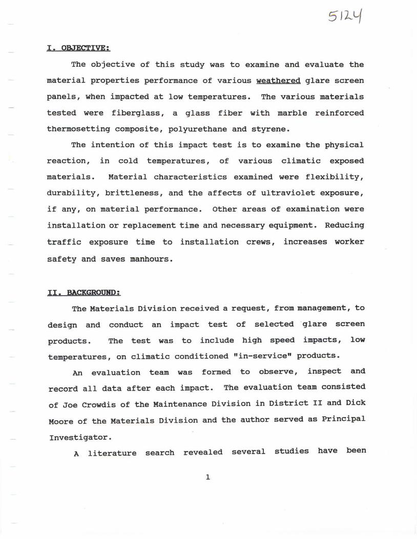
V. TEST CRIIIERIA:
Tnenty feet of each product was installed in consecutive
sections on portable concrete barrier rail. A 2 L/2 ton testing
vehicle was equipped with a retractable 3 inch diameter netal rod,
L2 inches above the top of the barrier rail (See Figrures 6 and 7).
This size truck was selected to insure the continuous momenturn of
45 miles per hour impact speed, throughout the entire lengrth of the
test. (See pictures L and 2) The material properties of the panels
may perforn differently in cold temperatures; therefore, the target
tenperature Was set at 25o F, ot below. The nurnber Of impacts was
to be determined by the evaluation team, based on the results of
the initial inpact.
10
tDIREMON C= 13A\EL
r€l:ii, ROD1]s'E
qrEEfrtl\l:A * a - ! Y
t 'F!:TTTFY g - g
trcrr 10 SCN;E
Figure 6
L 1

-
1 , l D? , i b4 l n? r 1 6V , l zl / , l : t
CrL$I
(Dz-
JV
or A
mtn' r
GtLA{10p7
80
f {i ---:zL
III
Il*s=::
II
se - se;;
Figure 7
L 2

VI. E\IALUATIOT CRITERIA:
The criteria selected for evaluation of performance of the
panel material included, but was not linited to, blade rotation'
dislocation, fracture, failure to self erect or shear failure'
Due to the different naterial conposition of tbe four
products, the performance of the individual products had to be
evaluated independently. Therefore, criteria for Carsonite and
Glasform was established for rtmeasure of leanrr and fracture, while
Safe-Hit and Syro Steelrs performance was measured by dislocation
and fracture.
The angle of lean was measured, from perpendicular to the base
rail, after the second impact, in both testS. This was used as a
means of determining if the products could be considered functional
of, llo[-functional. The angle of lean is defined as follows:
trSlightx =
rlrlOderatetr =
nsubstantialrr =
rggygSgft =
50 to L0"
10" to 20o
20o to 30"
Over 30o, Non-functional
L 3

\III- TEST RESULTS for EEBRUARY 17' 1993:
The initial impact test was scheduled for February L7, L993 at
Z:OO a.u. The test was slightly delayed, due to a l ight snon fall
from the previous night. A snow removal truck was dispatched to
the site and the first inpact began at 7:50 €r.D. with a recorded
temperature of 27o F and the second inpact at 8:10 a.m- at 30o F.
CAR.SOI\UIlTE
SUT.IUARY OF RESULTS ArTER II,IPACT #1, FEBRUARY L7 , 1993
IMPACT NI'UBER 1
Panel No. and Results Panel No. and Results
1. Shear to Panel
2. Shear to Panel
3. Shear to Panel
4. Shear to Panel
5. Shear to Panel
6. Shear to Panel
7. Shear to Panel
8. Shear to Panel
9. Shear to Panel
10. Shear to Panel
11. Shear to Panel
L2. Shear to Pane1
13. Shear to Panel
L4. Shear to Panel
15. Shear to Panel
16. No shear, moderate lean
Inpact Number 1: The panels splitr ot sheared, from the top down, 2 to 6
inches. AlI the panels remained in place and standing, but the bracket-base
rail connection bent, causing the panels to lean, slight to uoderate.
See picture #3.
t4

CAR.SODT-TE
SU!,II,IARY OF REST'LTS AFTER rupAcT #2, FEBRUARY L7, 1993
I!{PACT NT]!.TBER 2
Panel No. and Results Panel No. and Results
1 . Sp1 i t 24n , 11 " l ean
2 . sp l i t 13 ' , 12o l ean
3. Spli t 2O" , l-5o lean
4. Spl i t 24t t , 17" lean
5. Spl i t 18t t , 13o lean
6. Spl i t 16t t , 12o lean
7 . Spli t str, 12o lean
8. Spl i t L4" , 19o lean
9. Spl i t 2o" ,
1 0 . S p l i t L 4 n ,
1 1 . S p l i t 2 4 n ,
L2 . Sp l i t LT t t ,
13 . Sp l i t 2o " ,
L 4 . S p l i t 1 5 ' ,
15 . Sp l i t 18 t t ,
16 . 2 . s t r sP l i t
l lo lean
7" lean
90 lean
Llo lean
12o lean
12" lean
15o lean
at bracket, 18" lean
rnpact Nunber 2: lltre splits or shear failure on the panels lengthened' fron
the top down, as shown in picture #4. Three of the panels split to full
Iength. A snall split developed at the bracket of panel Sre. Although the
panels remained attached, the bracket bent, causing thern to lean' It uust be
noted that arthough the paner nateriar sprit, the product remained attached
and could be considered functional, until replaced, if it were in an trin-
servicerr situation-
15

SYFTO STEEI-
suut{ARY oF RESITLTS AFTER rl,lPACT #1, FEBRUARY 17, L993
IUPACT NT]I,TBER T.
Panel No. and Results Panel No. and Results
L. Dislocated 6. Tore at bolt
2. split top/tore at bolt 7 . Split topr/tore at bolt
3. Tore at bott 8. Split top/tore at bolt
4. Split top/tore at bolt 9. Split top,/tore at bolt
5. Tore at bolt LO. Tore at bolt
Inpact Number t-: Of the two carriage anchor bolts attaching the panel to the
base rai1, nine panels tore at this bolt, oi the inpact side. Additionally,
five of those nine panels also split at the top and panel #1 was dislocated.
See pictures 5 and 6.
t 6

SYR.O SITEEI-
ST'I'IUARY OF RESULTS AFTER IIIIPACT #2, FEBRUARY 17, 1993
TUPACT NT]ITBER 2
Panel No. and Results Panel No. and Results
1. Dislocated 6. Spfit top, Ioose
2. Top shattered, panel loose 7. Dislocated
3. Dislocated 8. Top shattered,, panel loose
4. Sp1it top, panel loose 9. Dislocated
5. Dislocated 10. Dislocated
Irapact Nunber 2: An additional five panels were dislocated after the second
irnpact. The four remaining panels tore, on the inpact side, at the anehor
bolt, leaving the panels loose and falling over. The angle of lean was not
neasured, however, because with no rigidity to the panels' they were
evaluated as non-functional.
t7

GI-ASFOFI-M
SUUI.IARY OF RESULTS AFTER II,IPACT #1, FEBRUARY 17, 1993
IMPACT NUI,IBER 1
Panel Nuraber and Resul-ts Panel Nunrber and Results
L. Panel OK, bolt PulI out
2 . * *
3 . * *
4 . * *
5 . * *
6 . * *
7 . * *
g . * *
9 . * *
1 0 . * *
L L . * *
1 2 . * *
1 3 . * *
L 4 . * *
1 5 . * *
1 6 . * *
L 7 . * *
L 8 . * *
1 9 . * *
20. 3tr spl i t at bracket
** bent bracket, slight lean.
Inpact Number 1: Panels #t through #19 were still standing, nith no damage
to the panel naterial, however the bracket bent, causing then to lean slight
to moderate. See picture #Z A small splitr otr panel #2O, developed at the
bracket. The panel naterial of #1 sustained no danage, but the bolt started
pull ing through the base rail, see picture #8.
1 8

GI-ASFOFIM
suuuARy oF RESULTS AFTER rttPACT #2, FEBRUARY L7' L993
IUPACT NI'I{BER 2
Panel Nurnber and Results Panel Number and Results
1. Dislocated lL. Bolt pul l out, severe lean
2. Pane1 OK, 22o Lean L2. Panel OK, L2" lean
3. 4.5t r sp l i t a t bracket , 15" lean l -3 . 7 t t sp l i t , 1Oo lean
4. Panel OK, L3o }ean 1-4. 5n sp l i t , bo l t pu l l out
5. Panel oK, L7" lean L5- Panel oK, 14o lean
6. Bol t pu l l out , 42o lean L6- 9r t sp l i t , 15o lean
7. 4n spli t at bracket, l-9o lean L7. 3rr spl i t at bracket, 14" Iean
8. Panel oK, 15o lean 18. 8 t r sp l i t , L2o lean
g. lrt spl i t at bracket, L4o lean 19. Panel OK, 160 lean
10. Panet OK, L8o lean 20. 3tr spl i t at bracket, 90 lean spli t
fmpact Number 2: Atl the panels were leaning due to the split running
through the entire length of the base rail. Panel #t was dislocated due to
the bolt pulJ-ing through the base rail. Panels #6 and #14 remained attached'
but were leaning severely due to the bolt pulling through the base rail, see
picture #g. Sixteen of the twenty panels remained fully functional
l-9

S A F E - I { - l F
suut{ARY OF RESItLTS AFTER IUPACT #L ' FEBRUARY 17, 1-993
IMPACT NI]!{BER 1-
Panel No. and Results Panel No. and Results
l - . Dislocated, blade base sheared 6. Dislocated, blade base sheared
2. Dislocated, blade base sheared 7. Shear at top of base, fal len over
3. No Darnage 8. Dislocated, blade base sheared
4. Dislocated, shear at top of base 9. Dislocated, blade base sheared
5. Dislocated, shear at top of base l-0. Dislocated, blade base sheared
Impact Nunber l-: out of 1o panels, 6 were dislocated due to the blade base
shearing off at the base rail. Three were dislocated due to the panel
shearing off at the top of the blade-base. Panel #7 was barely attached and
fallen over and was non-functional, see picture #10. Panel #3 was still in
place with no damage to any part of the assernbly. see pictures #tt'
20

SAFE-FI :E1T
SUI{I,TARY OF RESI'LTS AFTER IUPACT #2 ' FEBRUARY L7, L993
IUPACT NT'IITBER 2
Panel No. and Results Panel No. and Results
1-, Dis located,
2. Dis located,
3. Dis located,
4. Dis located'
5. Dis located,
Impact Nunber 2:
The product, as a
durabitity of the
base sheared
base sheared
base sheared
at top of base
at top of base
6. Dis located,
7. Dis located,
8. Dis located,
9. Dis located,
L0. Dis located,
blade base sheared
shear at toP of base
blade base sheared
blade base sheared
blade base sheared
blade
blade
blade
shear
shear
Panel #3 was dislocated due to the
whole, became non-functional when
panel material was apparent, with
blade base
dislocated,
no sign of
shearing off.
however; the
splitt ing.
2 L

VIII. TEST RESIITTS for I{ARCII 5' 1993:
The second test was conducted on lfarch
began at 6:30 €l.trl., with a tenperature of
conducted at 72A5, with a 31.5o F ternperature
CAR.SONITE
SUIITIIARY OF RESULTS AFTER II{PACT #1, !{ARCH 5' 1993
IUPACT NI]I{BER 1.
Panel No. and Result's Pane1 No, and Results
5, L993 and the first inPact
3Oo F, the second inPact was
recorded.
r- . spl i t
2 . Spl i t
3 . sp t i t
4 . Spl i t
5 . sp l i t
6 . Sp1i t
7 . sp l i t
8 . Spl i t
to panel
to panel
to panel
to panel
to panel
to panel
to panel
to panel
9. Split to Panel
10. Spl i t to Panel
11. Split to Panel
L2. Split to Pane1
L3. Split to Panel
L4. Split to Panel
L5. Split to Panel
L6. ro split, substantial lean
Inpact Number 1: The panel naterial began to splitr or shear, fron the top
down, 2 to I inches. Alf of the panels remain in-place and standing, but
bent at the bracket, causing the panels to lean, slight to substantial.
2 2

CAR.SODTITE
SUUMARY OF RESULTS AFTER II.TPACT #2, I,IARCH 5, 1-993
IUPACT NT'UBER, 2
Panel No. and Results Pane1 No. and Results
L . sp l i t 8 r r ,
2 . Sp l i t 8 r r ,
3 . S p l i t 2 r r ,
4 . Sp l i t 5 r r ,
5 . Sp l i t 2 r r ,
6 . S p l i t 4 n ,
7 . Spl i t 3r t ,
g . sp l i t 3 t r ,
L8o lean
18o lean
L9o lean
2oo lean
21o lean
l-9o lean
19o lean
22o lean
9 . Sp l i t 3 r r , 16o l ean
L0. Spl i t 3n, Lzo lean
1l - . sp l i t 5 t r , L6" lean
L2. Spl i t 3 t t , l -7o lean
13. Spt i t 2r t , L lo lean
L4. Spli t 4tr , l-5o lean
L5. Spl i t 2r r , L9o }ean
L6 . Sp l i t 1 [ , 28o l ean
rmpact Number 2: All panels remain in-place and functional The bracket to
base rail connection bent, causing the panels to lean. The angle of lean is
more severe and the shearing (splitting) of the panels lengthened after the
second irnpact. The damage to the panels was not as severe as the February
test. (See P5-ctures 12 and 13)
2 3

SYTLO SITEEI,
sItuMARy OF RESULTS AFTER TUPACT #1, !{ARCH 5 ' L993
II{PACT NUMBER 1
panel No. and Results Panel No, and Results
1-. Panel shattered, tore at bolt 6. Shattered top, tore at bolt
2. Tore at bolt 7. Split top and bottom
3. Dislocated 8- Tore at bolt
4. Sp1it top and bottorn 9. Shattered top, tore at bolt
5. Panel shattered, tore at bolt 1-0. Shattered top, tore at bolt
Inpact Nunber 1: The panels sustained splltting or shear failure to both
the top and botton. At the nounting anchor bolt, oD the inpact side' seven
panels tore at this bolt and #3 was dislocated'
2 4
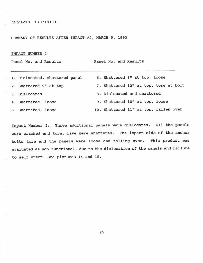
SYR.O STEEI.
- suuttARY oF RESI'LTS AFTER rl,tPACT #2, MARCH 5, 1993
II{PACT NI'MBER 2
Panel No. and Results Panel No. and Results
1. Dislocated, shattered panel 6. Shattered 8rr at top, Ioose
Z. Shattered gtr at top 7. Shattered Lzn at top, tore at bolt
3. Dislocated 8. Dislocated and shattered
4. Shattered, Ioose 9. Shattered l-0rr at top, loose
5. Shattered, loose 10. Shattered 1-t-[ at top, fallen over
Iurpact Nunber 2: Three additional panels were dislocated. AI1 the panels
- were cracked and torn, five were shattered. The inpact side of the anchor
bolts tore and the panels were loose and falling over. This product was
evaluated. as non-functional, due to the dislocation of the panels and failure
to self erect. See pictures L4 and l-5.
25

GI-ASF()TUM
SUlltlARY OF RESULTS AFTER IUPACT #L, MARCH 5, L993
IUPACT NI'UBER 1-
Panel Number and Results Panel Number and Results
1-. Base rail split
2. Substantial lean
3. Moderate lean
4. BoIt pull out, severe lean
5. slight lean
6. Slight lean
7. Sliqht lean
8. Slight lean
9. BoIt pull out, severe lean
10. Sl ight lean
LL. Sl ight lean
L2. Sl ight lean
L3. Sl ight lean
14. Sl ight lean
1,5. S1ight lean
L6. Sliqht lean
L7, Slight lean
1,8. Slight lean
19. sl ight lean
20. Slight lean, 3tr spl i t at bracket
Impact Nurnber 1: AII panels remained attached,
through the base rail on panels #4 and #9. Atl
bracket-base rail connection. Panel #Zo was
bracket, in two places. The base rail split
sections.
but the anchor bolts Pulled
the panels were bent at the
split 3 to 4 inches at the
the full length on both 10'
2 6

GI,ASFOFIryI
suilt{ARY oF RESIILTS AFTER TI,IPACT #2, II{ARCH 5, 1993
IUPACT NT'MBER 2
Panel Nunber and Results Panel Nunber and Results
1. Dislocated, bolt pul l out L1. Pane} OK, 11o, bolt pul l out
2. Pane1 OK, 49o lean, bolt pu1l out L2. Panel OK, l-4o lean
3. Panel oK, 47o lean, bolt pul l out 13. ztt spl i t at , L2o lean
4. Panel oK, 47o lean, bolt pul l out L4. Panel oK, L2o lean
5. Panel oK, 1,8" Iean 1-5. 6 .5t r sp l i t a t top, L2o lean
6. Panel OK, L8o lean 16. 3r sp l i t a t bracket , 13o lean
7 . 3 r r s p l i t a t b r a c k e t , L 7 . 1 r r s p t i t a t t o p , 1 3 o l e a n
5Lo lean, bo l t puI l out 18. 2 .5u sp l i t a t top, LZo lean
8. Panel OK, 5Oo lean, bo l t pu l } out L9. '2r t sp l i t a t top, 13o lean
9. panel OK, 42o lean, bo l t pu l l out 20.s t r sp l i t a t bracket , l0o lean
10. Dislocated, bolt PuII out
IrnBact Nurnber 2: panels #1 and #10 were dislocated due to the bracket anchor
bolt pulling through the base rail. Due to the dislocation and the severe
lean of panels, this product was evaluated as non-functional- See pictures 16
and L7 .
2 7

SAFE-I { :E1T
- SUUII{ARY OF RESULTS AFTER IMPACT #1, Ii{ARCH 5, ].993
IUPACT NT'UBER ].
Panel No. and Results Panel No. and Results
L. Dislocated, blade base sheared 6. Dislocated, blade base sheared
2. Dislocated, blade base sheared 7. No damage, sl ight lean
3. No damage, slight lean 8. Dislocated, blade base sheared
4. No damage, sl ight lean 9. Dislocated, blade base sheared
5. Dislocated, blade base sheared L0. Dislocated, blade base sheared
Irnpact Nunber 1: Seven of the ten panels were dislocated due to blade base
- shear failure. Panels 3, 4 and 7 remained attached with a slight lean. Panel
#9 was dislocated and carried by the irnpacting vehicle but the panel material
did not suffer any damage, such as splits.
2 8

S A F E - I { I T
stn{MARY OF RESULTS ArTER I.IcPACT #2 | II{ARCII 5, L993
rIi{PACT NTJIfBER 2
Panel No. and Results Panel No. and Results
1. Dislocated, blade base sheared 6. Dislocated, blade base sheared
2. Dislocated, blade base sheared 7. DJ.slocated, blade base sheared
3. Dislocated, blade base sheared 8. Dislocated, blade base sheared
4. Panel Ok, 50 lean 9. Dislocated, blade base sheared
5. Dislocated, blade base sheared 10. Dislocated, blade base sheared
Inpact Nunber 2: Panel #a was still attached with no damage to any part of
the assernbly. See pictures 18 and 19. Due to the dislocation of the panels'
this product was evaluated as non-functional. The panel naterial proved to
be very durable, with no evidence of splitting'
29

APPENDIX A
PHOTOGRAPHS
3 0

PHOTO tl
The retractable,3 inch metal rod andnethod of measurementfor the inpact device,set at L2 inchesabove the portableconcrete barrier rail.
PHC'TO '2
The 2 L/2 tontesting vehicleat 45 l.!PH, rightbefore inpact.

Prrrto t3
CARSONITE 2-L7-1,993
The split of thepanels and theIean, due to thebend in the bracket
PHCTTO t4
CARONITE 2-1,7-L993
the spli t ofthe panels and thelean, due to thebend in the bracket

PI|CIro t5
sYRO STEEL 2-L7-L993
The detachmentand looseness ofthe panels afterone impact.
PIICIIQ t6
syRo sTEEL 2-L7-Le93
The tear in thepanels, of the anchorbolt, on the inpactside.

PEqrc t7
GLASFOR!.! 2-L7-L993
The lean of thepanels, due to thebend in the bracket.
Plra$o ,8
GLASFORM 2*L7-L993
The base raildelaninating,causing the boltto puII through.

PHC'TO t9
GT.ASFORII 2-r7-L993
Panels #6 and #14leaning, due to thebolt pulling throughthe base rail.

PHC'ITC '1O
SAFE-HIT 2- I7-L993
Broken blade baseand panel #z shearedat the top of theblade base.
PHCITO 'T.T.
SAFE-HIT 2-L7-L993
Pane l # l i sundamaged and intact.

PHCIIO '12
CARSONITE 3-05-l-993
The spli t of thepanels and thelean, due to thebend in the bracket
PHCyrlO tr.3
CARONTTE 3-05-1993
The spl i t o fthe panels and theIean, due to thebend in the bracket

PHCrro t14
syRo STEEL 3-05-1993
The shattered topof the panels andthe tear at theanchor bolt.
PH(IICI '15
svRo STEEL 3-05-L993
The looseness of thepanels, due to thepanel tearing at theanchor bolt

PHC'|IIO t16
GLASFORM 3-05-1993
The bolt pul l ingthrough the base rai l ,causing the panels tolean .
PHCITO 'T-7
GLASFORM 3-05-1-993
The base rai ldelaminating andthe bolt pull ingthrough.
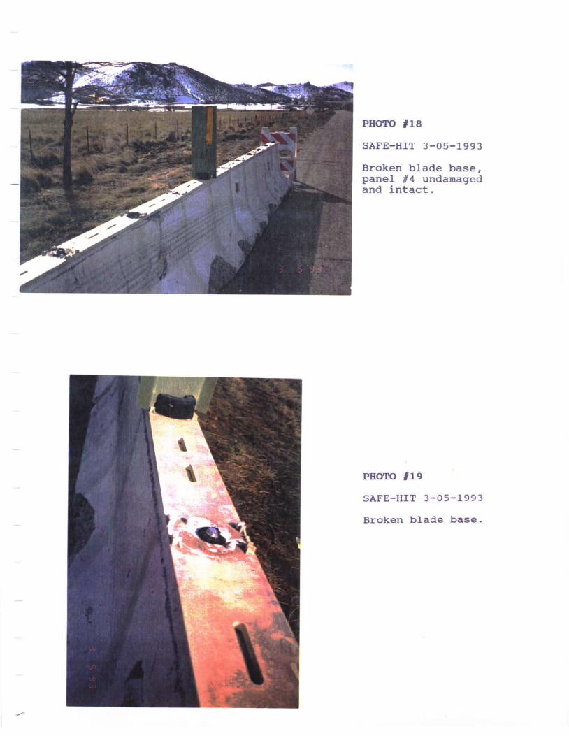
PHCIRO '18
SAFE-HIT 3-05-1993
Broken blade base,panel #a undamagedand in tact .
PHCTTIO '19
S A F E - H I T 3 - 0 5 - 1 9 9 3
Broken blade base.