Embed Size (px)
Citation preview

DENVER
HSA-120
INSTALLATION AND USER MANUAL
Alarm Security System™
ENG
Features
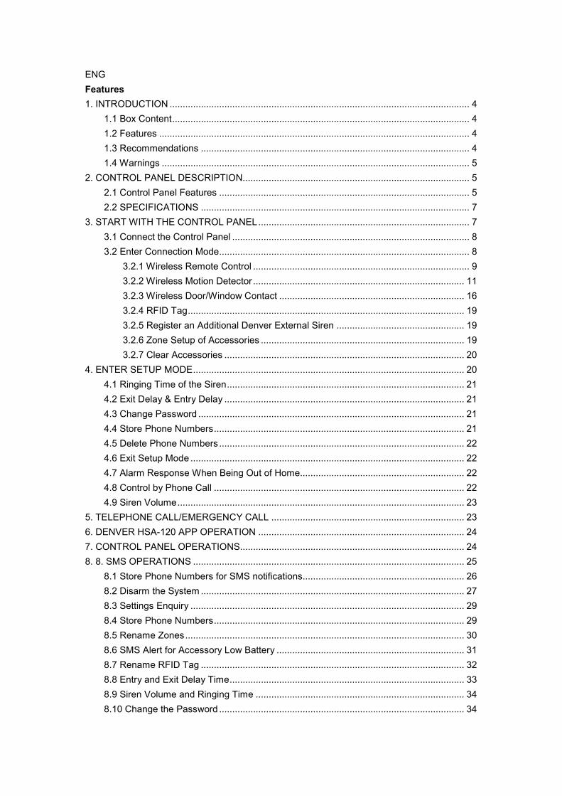
1. INTRODUCTION ................................................................................................................... 4
1.1 Box Content .................................................................................................................. 4
1.2 Features ....................................................................................................................... 4
1.3 Recommendations ....................................................................................................... 4
1.4 Warnings ...................................................................................................................... 5
2. CONTROL PANEL DESCRIPTION....................................................................................... 5
2.1 Control Panel Features ................................................................................................ 5
2.2 SPECIFICATIONS ....................................................................................................... 7
3. START WITH THE CONTROL PANEL ................................................................................. 7
3.1 Connect the Control Panel ........................................................................................... 8
3.2 Enter Connection Mode................................................................................................ 8
3.2.1 Wireless Remote Control ................................................................................... 9
3.2.2 Wireless Motion Detector ................................................................................. 11
3.2.3 Wireless Door/Window Contact ....................................................................... 16
3.2.4 RFID Tag .......................................................................................................... 19
3.2.5 Register an Additional Denver External Siren ................................................. 19
3.2.6 Zone Setup of Accessories .............................................................................. 19
3.2.7 Clear Accessories ............................................................................................ 20
4. ENTER SETUP MODE ........................................................................................................ 20
4.1 Ringing Time of the Siren ........................................................................................... 21
4.2 Exit Delay & Entry Delay ............................................................................................ 21
4.3 Change Password ...................................................................................................... 21
4.4 Store Phone Numbers ................................................................................................ 21
4.5 Delete Phone Numbers .............................................................................................. 22
4.6 Exit Setup Mode ......................................................................................................... 22
4.7 Alarm Response When Being Out of Home............................................................... 22
4.8 Control by Phone Call ................................................................................................ 22
4.9 Siren Volume .............................................................................................................. 23
5. TELEPHONE CALL/EMERGENCY CALL .......................................................................... 23
6. DENVER HSA-120 APP OPERATION ............................................................................... 24
7. CONTROL PANEL OPERATIONS...................................................................................... 24
8. 8. SMS OPERATIONS ........................................................................................................ 25
8.1 Store Phone Numbers for SMS notifications.............................................................. 26
8.2 Disarm the System ..................................................................................................... 27
8.3 Settings Enquiry ......................................................................................................... 29
8.4 Store Phone Numbers ................................................................................................ 29
8.5 Rename Zones ........................................................................................................... 30
8.6 SMS Alert for Accessory Low Battery ........................................................................ 31
8.7 Rename RFID Tag ..................................................................................................... 32
8.8 Entry and Exit Delay Time .......................................................................................... 33
8.9 Siren Volume and Ringing Time ................................................................................ 34
8.10 Change the Password .............................................................................................. 34

8.11 Change System Language ....................................................................................... 35
8.12 Restore System to Factory Settings by SMS ........................................................... 36
9. FAQ ..................................................................................................................................... 36
10. STANDARDS..................................................................................................................... 37
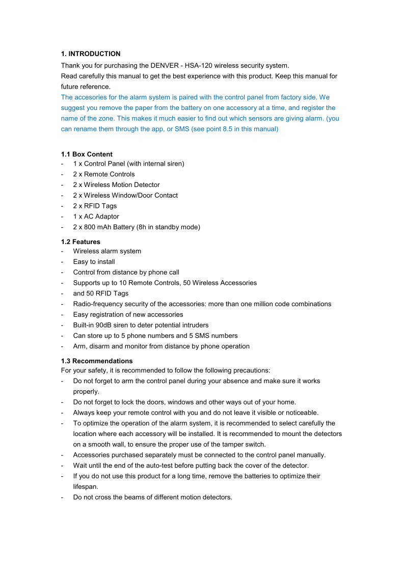
1. INTRODUCTION
Thank you for purchasing the DENVER - HSA-120 wireless security system.
Read carefully this manual to get the best experience with this product. Keep this manual for
future reference.
The accesories for the alarm system is paired with the control panel from factory side. We
suggest you remove the paper from the battery on one accessory at a time, and register the
name of the zone. This makes it much easier to find out which sensors are giving alarm. (you
can rename them through the app, or SMS (see point 8.5 in this manual)
1.1 Box Content
- 1 x Control Panel (with internal siren)
- 2 x Remote Controls
- 2 x Wireless Motion Detector
- 2 x Wireless Window/Door Contact
- 2 x RFID Tags
- 1 x AC Adaptor
- 2 x 800 mAh Battery (8h in standby mode)
1.2 Features
- Wireless alarm system
- Easy to install
- Control from distance by phone call
- Supports up to 10 Remote Controls, 50 Wireless Accessories
- and 50 RFID Tags
- Radio-frequency security of the accessories: more than one million code combinations
- Easy registration of new accessories
- Built-in 90dB siren to deter potential intruders
- Can store up to 5 phone numbers and 5 SMS numbers
- Arm, disarm and monitor from distance by phone operation
1.3 Recommendations
For your safety, it is recommended to follow the following precautions:
- Do not forget to arm the control panel during your absence and make sure it works
properly.
- Do not forget to lock the doors, windows and other ways out of your home.
- Always keep your remote control with you and do not leave it visible or noticeable.
- To optimize the operation of the alarm system, it is recommended to select carefully the
location where each accessory will be installed. It is recommended to mount the detectors
on a smooth wall, to ensure the proper use of the tamper switch.
- Accessories purchased separately must be connected to the control panel manually.
- Wait until the end of the auto-test before putting back the cover of the detector.
- If you do not use this product for a long time, remove the batteries to optimize their
lifespan.
- Do not cross the beams of different motion detectors.
1.4 Warnings
- The control panel is provided with a separate battery. Do not scrap used batteries
anywhere. They shall be recycled in accordance with the EU Directives 91/157/EEC and
93/86/EEC.
- Do not open the case of the control panel and do not repair it yourself. If you encounter an
issue with the product, contact a qualified personnel (technician or manufacturer's
service).
- Take care of this product and do not let water get into it as it may damage the product.
- Place the control panel in a cool, dry and well-ventilated area. Do not install detectors near
heating, cooling, or ventilation.
- Do not use detergent or other flammable materials to clean this unit.
- Do not let your device fall on the floor.
- Remove the battery holder cover with care.
- DENVER Electronics is not to be held responsible in case of burglary, theft, loss or
damage to house/persons/other, power cut off or any other issues.
2. CONTROL PANEL DESCRIPTION
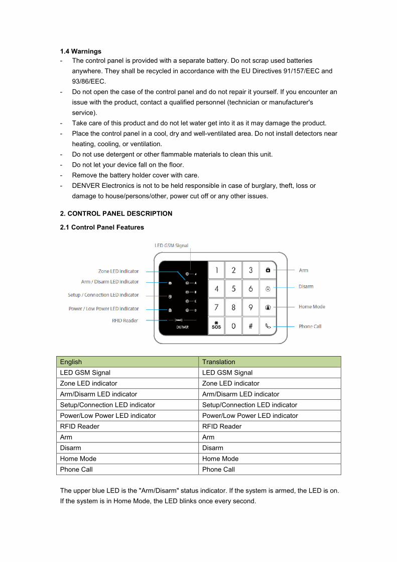
2.1 Control Panel Features
English Translation
LED GSM Signal LED GSM Signal
Zone LED indicator Zone LED indicator
Arm/Disarm LED indicator Arm/Disarm LED indicator
Setup/Connection LED indicator Setup/Connection LED indicator
Power/Low Power LED indicator Power/Low Power LED indicator
RFID Reader RFID Reader
Arm Arm
Disarm Disarm
Home Mode Home Mode
Phone Call Phone Call
The upper blue LED is the "Arm/Disarm" status indicator. If the system is armed, the LED is on.
If the system is in Home Mode, the LED blinks once every second.
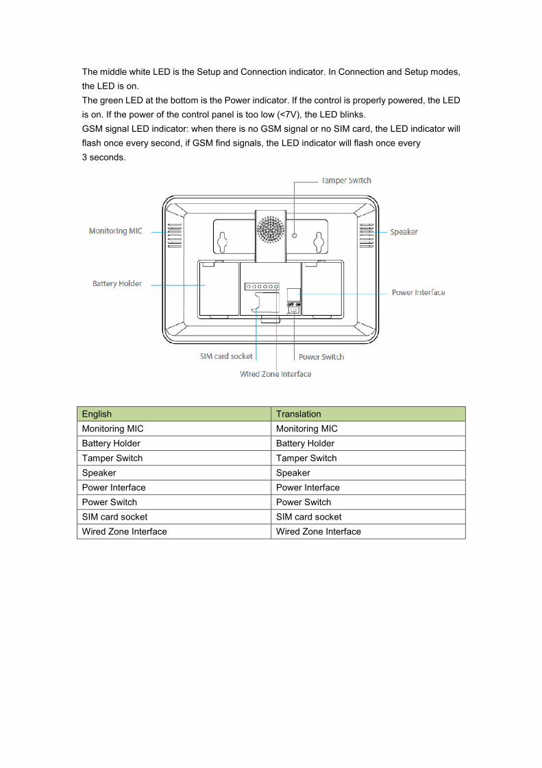
The middle white LED is the Setup and Connection indicator. In Connection and Setup modes,
the LED is on.
The green LED at the bottom is the Power indicator. If the control is properly powered, the LED
is on. If the power of the control panel is too low (<7V), the LED blinks.
GSM signal LED indicator: when there is no GSM signal or no SIM card, the LED indicator will
flash once every second, if GSM find signals, the LED indicator will flash once every
3 seconds.
English Translation
Monitoring MIC Monitoring MIC
Battery Holder Battery Holder
Tamper Switch Tamper Switch
Speaker Speaker
Power Interface Power Interface
Power Switch Power Switch
SIM card socket SIM card socket
Wired Zone Interface Wired Zone Interface
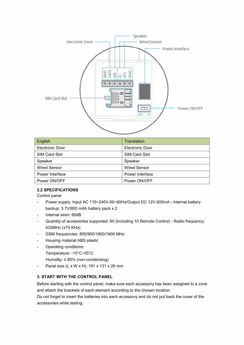
English Translation
Electronic Door Electronic Door
SIM Card Slot SIM Card Slot
Speaker Speaker
Wired Sensor Wired Sensor
Power Interface Power Interface
Power ON/OFF Power ON/OFF
2.2 SPECIFICATIONS
Control panel
- Power supply: Input AC 110~240V-50~60Hz/Output DC 12V-500mA - Internal battery
backup: 3.7V/800 mAh battery pack x 2
- Internal siren: 90dB
- Quantity of accessories supported: 60 (including 10 Remote Control) - Radio frequency:
433MHz (±75 KHz)
- GSM frequencies: 850/900/1800/1900 MHz
- Housing material ABS plastic
- Operating conditions:
Temperature: -10°C~55°C
Humidity: ≤ 80% (non-condensing)
- Panel size (L x W x H): 191 x 131 x 26 mm
3. START WITH THE CONTROL PANEL
Before starting with the control panel, make sure each accessory has been assigned to a zone
and attach the brackets of each element according to the chosen location.
Do not forget to insert the batteries into each accessory and do not put back the cover of the
accessories while testing.
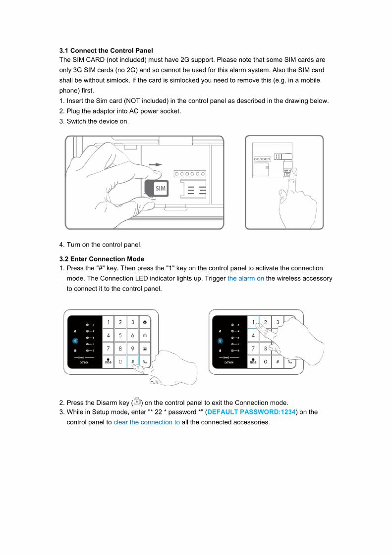
3.1 Connect the Control Panel
The SIM CARD (not included) must have 2G support. Please note that some SIM cards are
only 3G SIM cards (no 2G) and so cannot be used for this alarm system. Also the SIM card
shall be without simlock. If the card is simlocked you need to remove this (e.g. in a mobile
phone) first.
1. Insert the Sim card (NOT included) in the control panel as described in the drawing below.
2. Plug the adaptor into AC power socket.
3. Switch the device on.
4. Turn on the control panel.
3.2 Enter Connection Mode
1. Press the "#" key. Then press the "1" key on the control panel to activate the connection
mode. The Connection LED indicator lights up. Trigger the alarm on the wireless accessory
to connect it to the control panel.
2. Press the Disarm key ( ) on the control panel to exit the Connection mode.
3. While in Setup mode, enter "* 22 * password *" (DEFAULT PASSWORD:1234) on the
control panel to clear the connection to all the connected accessories.
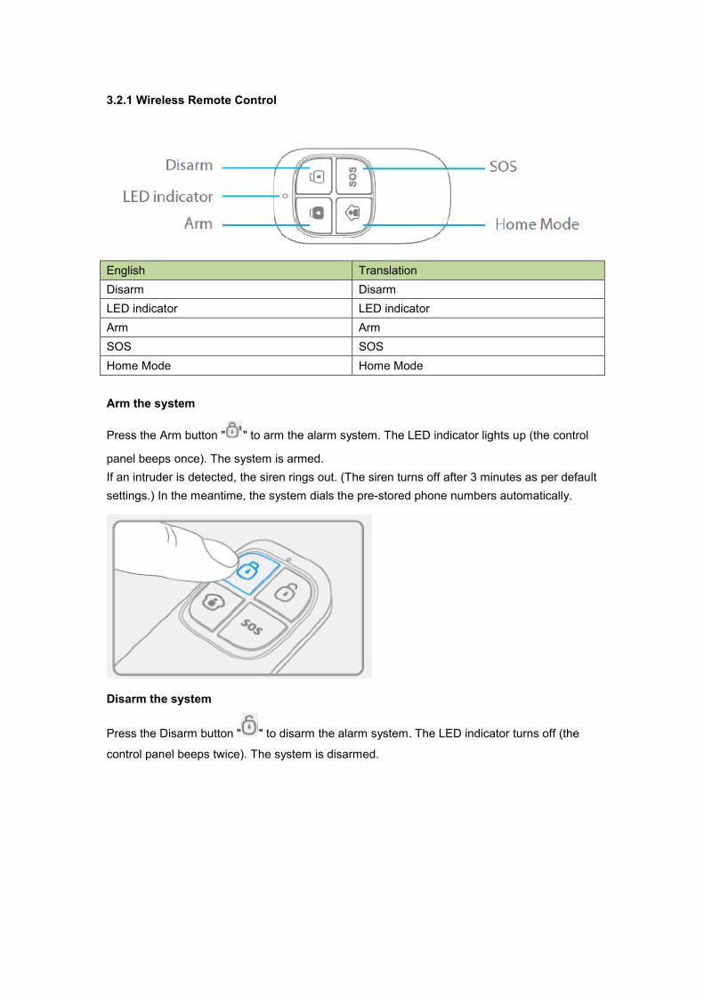
3.2.1 Wireless Remote Control
English Translation
Disarm Disarm
LED indicator LED indicator
Arm Arm
SOS SOS
Home Mode Home Mode
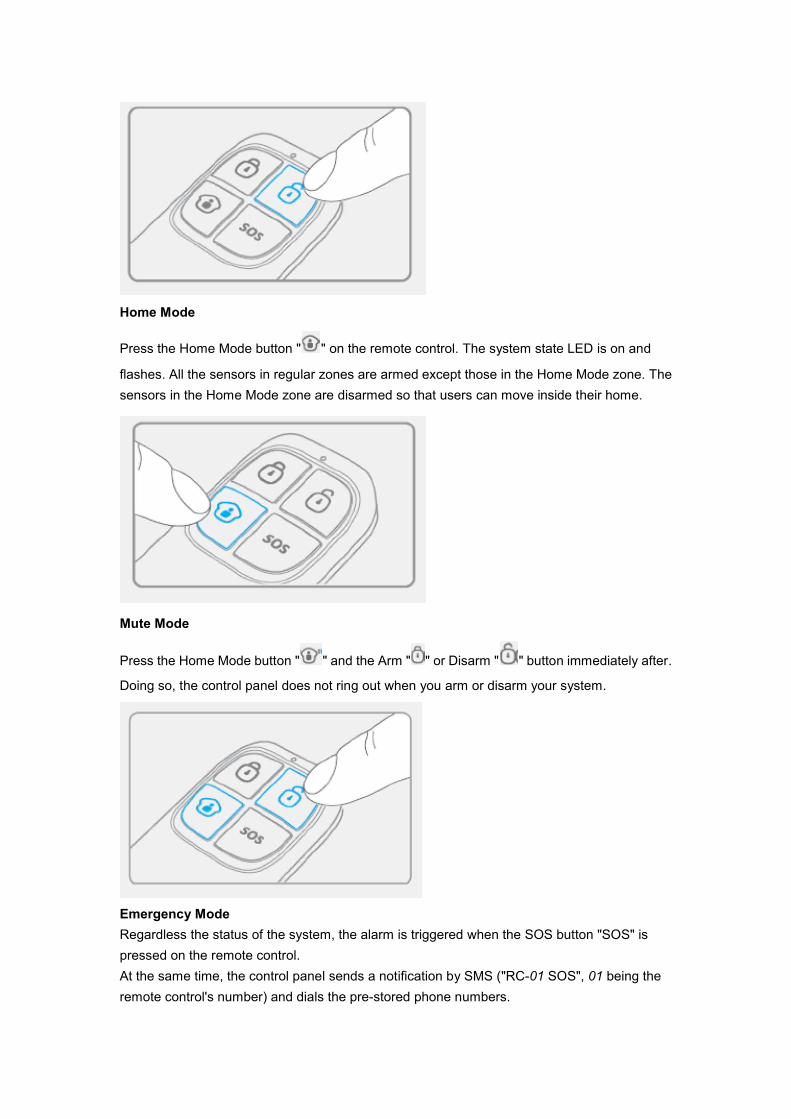
Arm the system
Press the Arm button " " to arm the alarm system. The LED indicator lights up (the control
panel beeps once). The system is armed.
If an intruder is detected, the siren rings out. (The siren turns off after 3 minutes as per default
settings.) In the meantime, the system dials the pre-stored phone numbers automatically.
Disarm the system
Press the Disarm button " " to disarm the alarm system. The LED indicator turns off (the
control panel beeps twice). The system is disarmed.
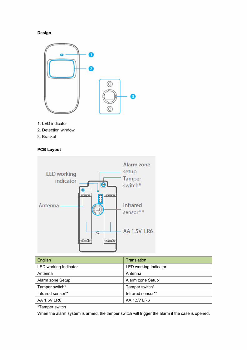
Home Mode
Press the Home Mode button " " on the remote control. The system state LED is on and
flashes. All the sensors in regular zones are armed except those in the Home Mode zone. The
sensors in the Home Mode zone are disarmed so that users can move inside their home.
Mute Mode
Press the Home Mode button " " and the Arm " " or Disarm " " button immediately after.
Doing so, the control panel does not ring out when you arm or disarm your system.
Emergency Mode
Regardless the status of the system, the alarm is triggered when the SOS button "SOS" is
pressed on the remote control.
At the same time, the control panel sends a notification by SMS ("RC-01 SOS", 01 being the
remote control's number) and dials the pre-stored phone numbers.

Register in the control panel
Enter Connection Mode on the control panel. Push the button “#”, and then push “1” on the
control panel.
Press any button on the remote control to register it to the control panel
Specifications
Power supply: DC 3V (CR2025 button battery x1)
Static current: 10 uA
Operating current: ≤7 mA
Transmission distance: ≤ 80 m (in open area)
Radio-frequency: 433MHz (±75KHz)
Housing material: ABS plastic
Operating conditions: Temperature: -10°C~+55°C
Relative Humidity: ≤80% (non-condensing)
Dimensions: 57 x 31 x 11 mm
3.2.2 Wireless Motion Detector
Features
The high performance wireless motion detector is boasting a digital dual-core fuzzy logic
infrared control chip with intelligent analysis. This technology identifies interferences created
by body motion and reduces the false alarm rate.
With automatic temperature compensation and anti-air turbulence technology, it easily adapts
to environmental changes.
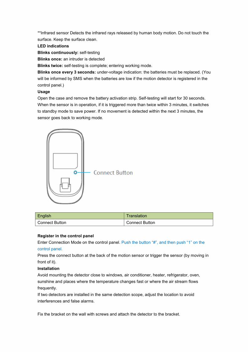
Design
1. LED indicator
2. Detection window
3. Bracket
PCB Layout
English Translation
LED working Indicator LED working Indicator
Antenna Antenna
Alarm zone Setup Alarm zone Setup
Tamper switch* Tamper switch*
Infrared sensor** Infrared sensor**
AA 1.5V LR6 AA 1.5V LR6
*Tamper switch
When the alarm system is armed, the tamper switch will trigger the alarm if the case is opened.
**Infrared sensor Detects the infrared rays released by human body motion. Do not touch the
surface. Keep the surface clean.
LED indications
Blinks continuously: self-testing
Blinks once: an intruder is detected
Blinks twice: self-testing is complete; entering working mode.
Blinks once every 3 seconds: under-voltage indication: the batteries must be replaced. (You
will be informed by SMS when the batteries are low if the motion detector is registered in the
control panel.)
Usage
Open the case and remove the battery activation strip. Self-testing will start for 30 seconds.
When the sensor is in operation, if it is triggered more than twice within 3 minutes, it switches
to standby mode to save power. If no movement is detected within the next 3 minutes, the
sensor goes back to working mode.
English Translation
Connect Button Connect Button
Register in the control panel
Enter Connection Mode on the control panel. Push the button “#”, and then push “1” on the
control panel.
Press the connect button at the back of the motion sensor or trigger the sensor (by moving in
front of it).
Installation
Avoid mounting the detector close to windows, air conditioner, heater, refrigerator, oven,
sunshine and places where the temperature changes fast or where the air stream flows
frequently.
If two detectors are installed in the same detection scope, adjust the location to avoid
interferences and false alarms.
Fix the bracket on the wall with screws and attach the detector to the bracket.

Adjust the bracket to change the detection distance and angle. It is recommended to mount
the detector 2,2 m from the ground.
English Translation
Top Top
Ground Ground
Bottom Bottom
The detector is more sensitive to cross movements than vertical movements.
English Translation
Top view Top view
Side view Side view
Test
A. After the installation, turn the detector on. After one minute of self-testing, press the test
button, walk in the scope of detection and watch the LED indicator to make sure the
detector is working.
B. The LED indicator blinks once when body movement is detected.
C. Adjust the detector angle to achieve the best detection performance.
Specifications
Power supply
DC 3V (AA 1.5V LR6 Batteries x 2)
Static current
≤ 30 uA
Alarm current
≤ 15 mA
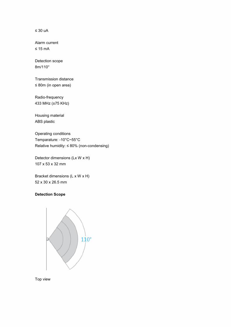
Detection scope
8m/110°
Transmission distance
≤ 80m (in open area)
Radio-frequency
433 MHz (±75 KHz)
Housing material
ABS plastic
Operating conditions
Temparature: -10°C~55°C
Relative humidity: ≤ 80% (non-condensing)
Detector dimensions (Lx W x H)
107 x 53 x 32 mm
Bracket dimensions (L x W x H)
52 x 30 x 26.5 mm
Detection Scope
Top view
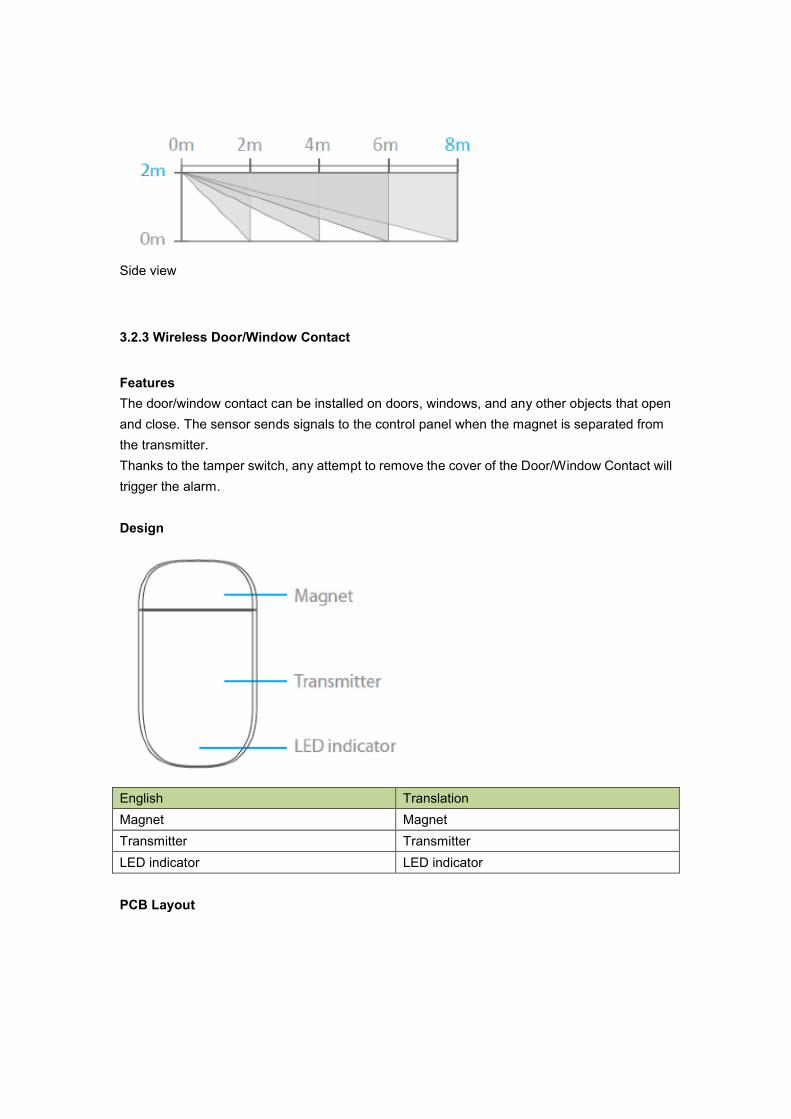
Side view
3.2.3 Wireless Door/Window Contact
Features
The door/window contact can be installed on doors, windows, and any other objects that open
and close. The sensor sends signals to the control panel when the magnet is separated from
the transmitter.
Thanks to the tamper switch, any attempt to remove the cover of the Door/Window Contact will
trigger the alarm.
Design
English Translation
Magnet Magnet
Transmitter Transmitter
LED indicator LED indicator
PCB Layout
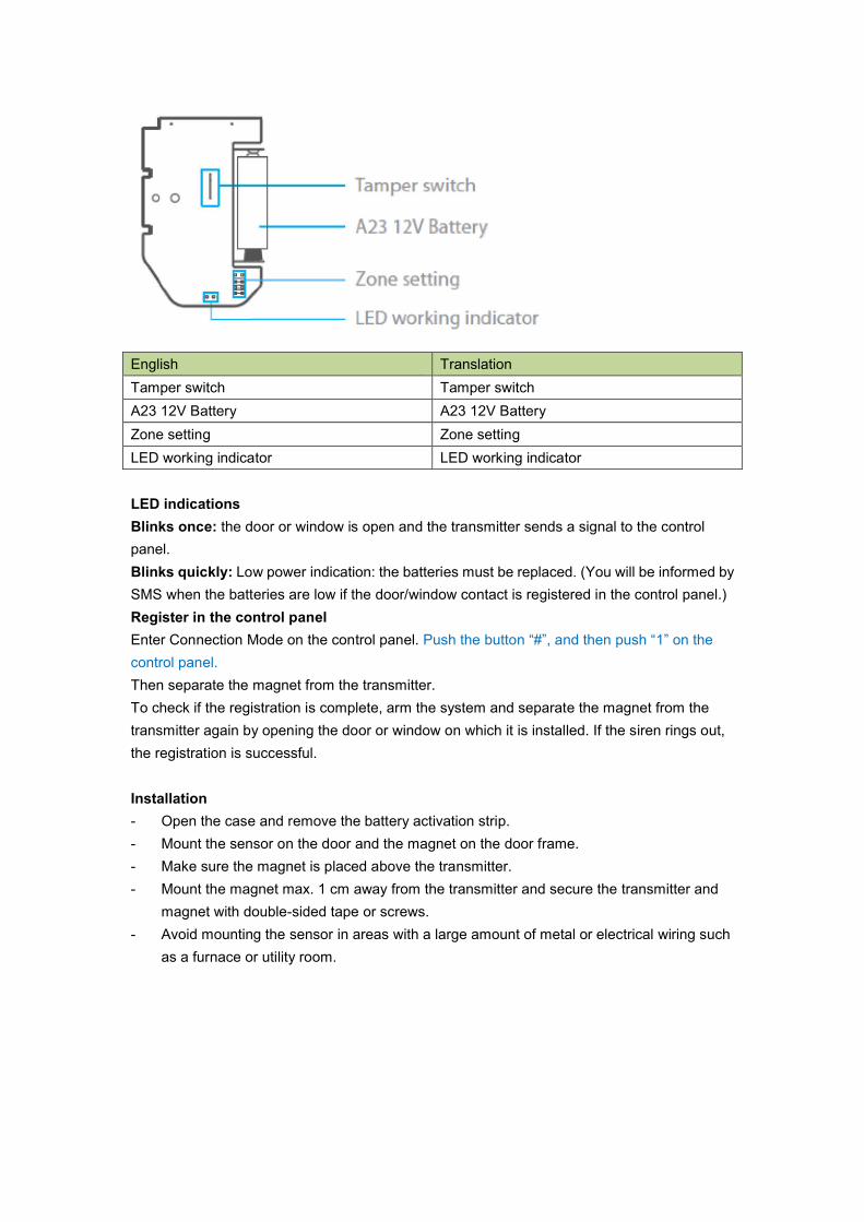
English Translation
Tamper switch Tamper switch
A23 12V Battery A23 12V Battery
Zone setting Zone setting
LED working indicator LED working indicator
LED indications
Blinks once: the door or window is open and the transmitter sends a signal to the control
panel.
Blinks quickly: Low power indication: the batteries must be replaced. (You will be informed by
SMS when the batteries are low if the door/window contact is registered in the control panel.)
Register in the control panel
Enter Connection Mode on the control panel. Push the button “#”, and then push “1” on the
control panel.
Then separate the magnet from the transmitter.
To check if the registration is complete, arm the system and separate the magnet from the
transmitter again by opening the door or window on which it is installed. If the siren rings out,
the registration is successful.
Installation
- Open the case and remove the battery activation strip.
- Mount the sensor on the door and the magnet on the door frame.
- Make sure the magnet is placed above the transmitter.
- Mount the magnet max. 1 cm away from the transmitter and secure the transmitter and
magnet with double-sided tape or screws.
- Avoid mounting the sensor in areas with a large amount of metal or electrical wiring such
as a furnace or utility room.
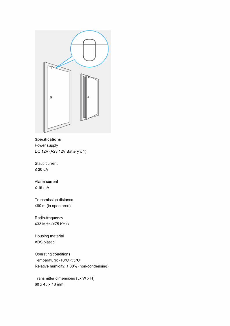
Specifications
Power supply
DC 12V (A23 12V Battery x 1)
Static current
≤ 30 uA
Alarm current
≤ 15 mA
Transmission distance
≤80 m (in open area)
Radio-frequency
433 MHz (±75 KHz)
Housing material
ABS plastic
Operating conditions
Temparature: -10°C~55°C
Relative humidity: ≤ 80% (non-condensing)
Transmitter dimensions (Lx W x H)
60 x 45 x 18 mm
Magnet dimensions (Lx W x H)
45 x 19 x 17,5 mm
3.2.4 RFID Tag
Features
The RFID tag enables you to disarm your system by swiping it in front of the RFID reader on
the control panel.
Register the RFID tag in the alarm system
Enter Connection Mode on the control panel. Push the button “#”, and then push “1” on the
control panel.
Swipe the RFID tag in front of the RFID reader on the control panel.
Specifications
Dimensions
30 x 30 x 6 mm
3.2.5 Register an Additional Denver External Siren
The control panel of the HSA-120 features a built-in 90 dB siren.
Your Denver security systems supports additional indoor and/or outdoor sirens (NOT included)
so to enable you to extend your system according to your needs.
To register an additional Denver siren, refer to the instructions provided in the manual that
comes with your siren.
For more information on sirens and accessories compatible with Denver security systems, visit
our website denver-electronics.com
3.2.6 Zone Setup of Accessories
Every detector can be assigned to 4 different categories of zones: Home Mode Zone, Delay
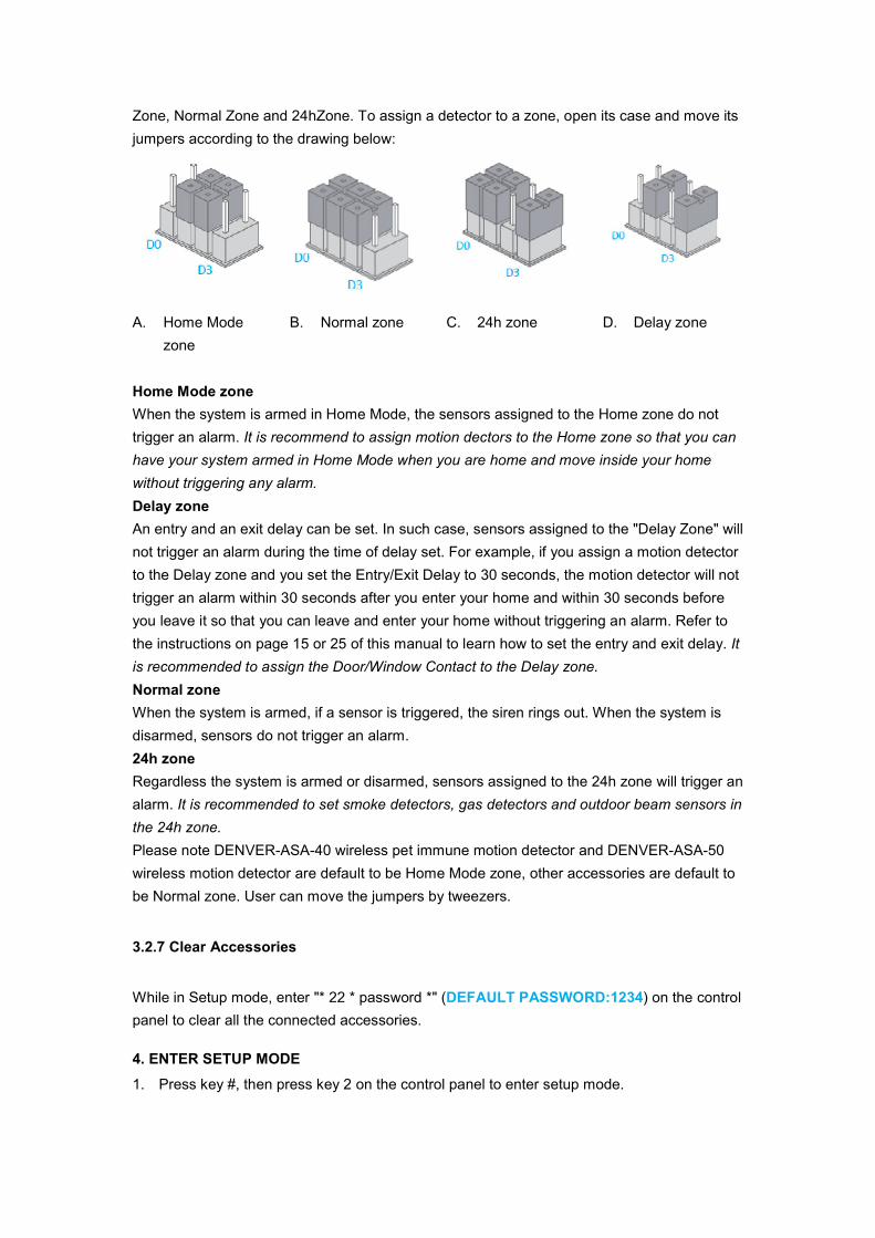
Zone, Normal Zone and 24hZone. To assign a detector to a zone, open its case and move its
jumpers according to the drawing below:
A. Home Mode
zone
B. Normal zone C. 24h zone D. Delay zone
Home Mode zone
When the system is armed in Home Mode, the sensors assigned to the Home zone do not
trigger an alarm. It is recommend to assign motion dectors to the Home zone so that you can
have your system armed in Home Mode when you are home and move inside your home
without triggering any alarm.
Delay zone
An entry and an exit delay can be set. In such case, sensors assigned to the "Delay Zone" will
not trigger an alarm during the time of delay set. For example, if you assign a motion detector
to the Delay zone and you set the Entry/Exit Delay to 30 seconds, the motion detector will not
trigger an alarm within 30 seconds after you enter your home and within 30 seconds before
you leave it so that you can leave and enter your home without triggering an alarm. Refer to
the instructions on page 15 or 25 of this manual to learn how to set the entry and exit delay. It
is recommended to assign the Door/Window Contact to the Delay zone.
Normal zone
When the system is armed, if a sensor is triggered, the siren rings out. When the system is
disarmed, sensors do not trigger an alarm.
24h zone
Regardless the system is armed or disarmed, sensors assigned to the 24h zone will trigger an
alarm. It is recommended to set smoke detectors, gas detectors and outdoor beam sensors in
the 24h zone.
Please note DENVER-ASA-40 wireless pet immune motion detector and DENVER-ASA-50
wireless motion detector are default to be Home Mode zone, other accessories are default to
be Normal zone. User can move the jumpers by tweezers.
3.2.7 Clear Accessories
While in Setup mode, enter "* 22 * password *" (DEFAULT PASSWORD:1234) on the control
panel to clear all the connected accessories.
4. ENTER SETUP MODE
1. Press key #, then press key 2 on the control panel to enter setup mode.

4.1 Ringing Time of the Siren
Example: Set the ringing time to be 5 minutes
Enter into Setup mode, type "*1*5*"
You hear "Operation succeeded": the setup is successful.
Note
The ringing time can be set from 1 to 9 minutes. Default setting: 5 minutes.
4.2 Exit Delay & Entry Delay
Example: Program exit delay to be 60 seconds
Enter into Setup mode, type "*2*60*"
You hear "Operation succeeded": the setup is successful.
Note
The delay time can be set from 0 to 300 seconds.
Default setting: no delay (0 seconds).
Example: Program entry delay to be 50 seconds.
Enter into Setup mode, type "*3*50*"
You hear "Operation succeeded": the setup is successful.
Once the function has been set, the panel will beep every second after having armed the
system. The beeps will speed up in the last 15 seconds. If an intruder is detected, the alarm
and the dialing will be delayed accordingly.
4.3 Change Password
Enter into Setup mode, type "*9*new password*".
You hear "Operation succeeded": the setup is successful.
Note
The password must consist of 4 digits (0 to 9).
Default password: 1234.
4.4 Store Phone Numbers
Example: store the 1st phone number as 12345678.
Enter into Setup mode, type #1#12345678#
You hear "Operation succeeded": the setup is successful.
Example 2: store the 2nd phone number as 23456789.

Enter into Setup mode, input #2#23456789#
You hear "Operation succeeded": the setup is successful.
Up to 10 phone numbers can be stored.
Note
The 1st to the 5th stored phone numbers are for calls from the alarm system.
The 6th to the 10th phone numbers are for SMS alert messages.
You hear "Operation succeeded": the setup is successful.
4.5 Delete Phone Numbers
Example: delete the 1st phone number.
Enter into Setup mode, type "#1##"
You hear "Operation succeeded": the setup is successful.
Example: delete the 2nd phone number.
Enter setup mode, type "#2##"
You hear "Operation succeeded": the setup is successful.
Note
Delete all existing phone numbers: "#*##"
4.6 Exit Setup Mode
Press the Disarm key on the control panel to exit the Setup mode until you hear 2 beeps and
the setup LED indicator blacks out: the system has exited the Setup mode
4.7 Alarm Response When Being Out of Home
If the system detects an intrusion, the siren will ring out immediately, and the control panel will
send alert SMS and dial the pre-stored phone numbers. The user can monitor the site from
distance and control the system by phone when receiving the call from the alarm system.
Note
No need to type password to control the system from distance when receiving the call from the
alarm system.
4.8 Control by Phone Call
Method 1
When an alarm has been triggered, the control panel dials the pre-stored phone numbers.
When you take the call, you can control the panel from distance according to the instructions in
the table below.
Method 2
1. Dial the telephone number of the SIM card in your control panel.
2. Enter your password followed by "#".
3. Select the operations to control the panel (see instructions in the table below).
Note
The call will end automatically if you do not send any command within 30 seconds.
*Default password is 1234.
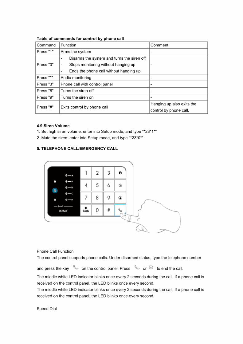
Table of commands for control by phone call
Command Function Comment
Press "1" Arms the system -
Press "0"
- Disarms the system and turns the siren off
- Stops monitoring without hanging up
- Ends the phone call without hanging up
-
Press "*" Audio monitoring -
Press "3" Phone call with control panel -
Press "6" Turns the siren off -
Press "9" Turns the siren on -
Press "#" Exits control by phone call Hanging up also exits the
control by phone call.
4.9 Siren Volume
1. Set high siren volume: enter into Setup mode, and type "*23*1*"
2. Mute the siren: enter into Setup mode, and type "*23*0*"
5. TELEPHONE CALL/EMERGENCY CALL
Phone Call Function
The control panel supports phone calls: Under disarmed status, type the telephone number
and press the key on the control panel. Press or to end the call.
The middle white LED indicator blinks once every 2 seconds during the call. If a phone call is
received on the control panel, the LED blinks once every second.
The middle white LED indicator blinks once every 2 seconds during the call. If a phone call is
received on the control panel, the LED blinks once every second.
Speed Dial
This function is only available when the system is disarmed.
Press the Call button " " on the control
panel for 3 seconds: the panel autodials
the first stored phone number.
Press the Call button " " to end the call.
SOS Emergency Function
Regardless the status of the system, the alarm is triggered when the Panic button {SOS} is
pressed on the control panel for 3 seconds.
Disarm the system on the control panel.
If the alarm system rings out, the user must type the password and the disarm button { } to
disarm the alarm system.
This operation must be completed in 15 seconds.
6. DENVER HSA-120 APP OPERATION
The app DENVER HSA-120 is available for download on Google Play and the App Store. To
find the app in the Google Play and the App Store, search "DENVER HSA-120".
You need to save at least one SMS number in the control panel before you can control the
alarm system via the app. (This is the phonenumber for the phone you want to use to control
the alarmsystem with)
In the app, click on "Arm" or "Disarm" to respectively arm or disarm the system.
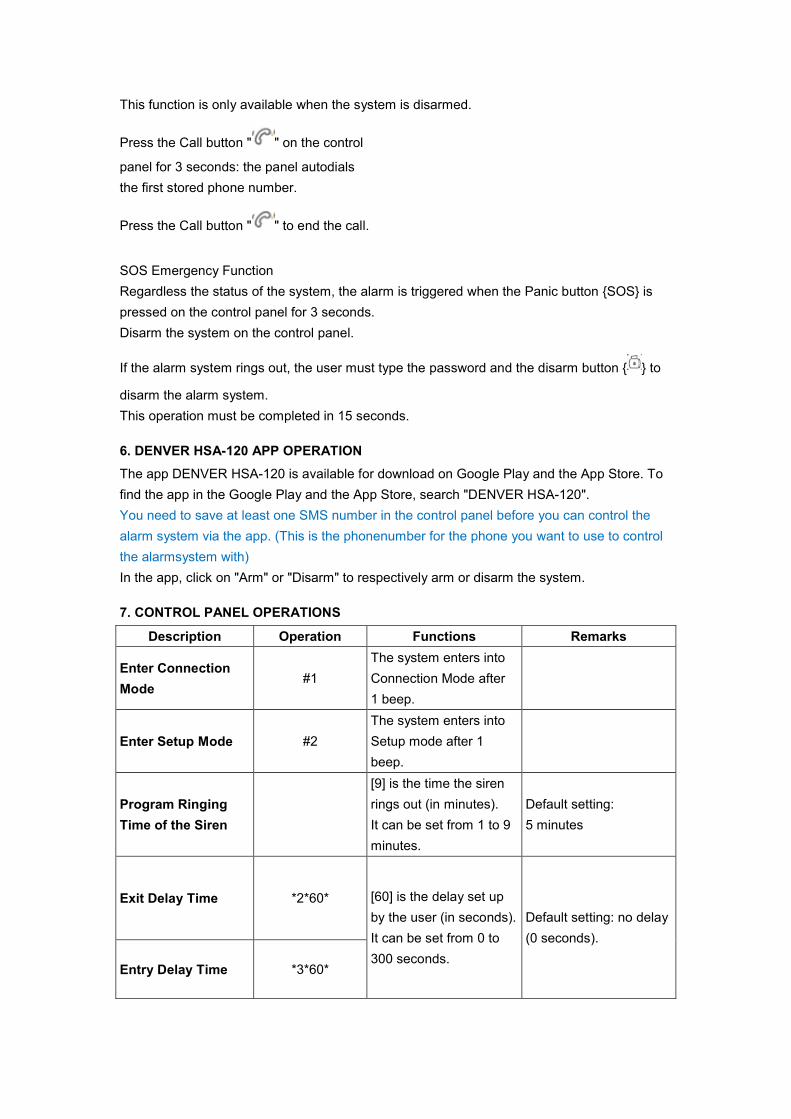
7. CONTROL PANEL OPERATIONS
Description Operation Functions Remarks
Enter Connection
Mode #1
The system enters into
Connection Mode after
1 beep.
Enter Setup Mode #2
The system enters into
Setup mode after 1
beep.
Program Ringing
Time of the Siren
[9] is the time the siren
rings out (in minutes).
It can be set from 1 to 9
minutes.
Default setting:
5 minutes
Exit Delay Time *2*60* [60] is the delay set up
by the user (in seconds).
It can be set from 0 to
300 seconds.
Default setting: no delay
(0 seconds).
Entry Delay Time *3*60*
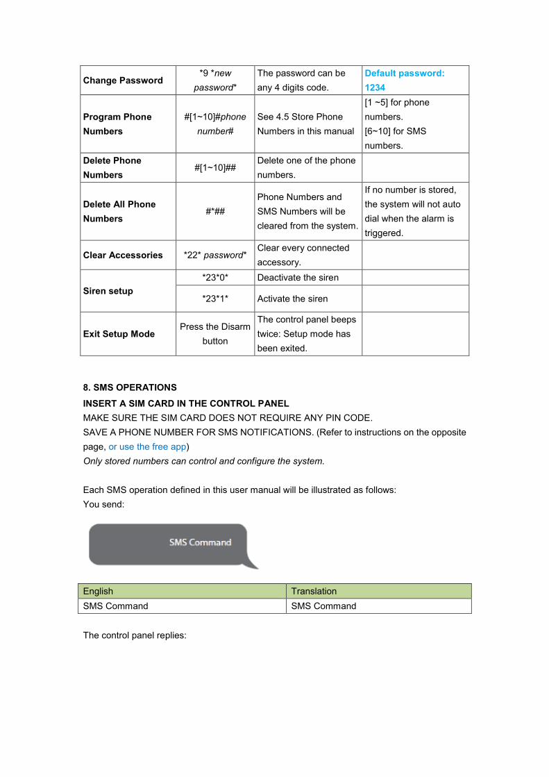
Change Password *9 *new
password*
The password can be
any 4 digits code.
Default password:
1234
Program Phone
Numbers
#[1~10]#phone
number#
See 4.5 Store Phone
Numbers in this manual
[1 ~5] for phone
numbers.
[6~10] for SMS
numbers.
Delete Phone
Numbers #[1~10]##
Delete one of the phone
numbers.
Delete All Phone
Numbers #*##
Phone Numbers and
SMS Numbers will be
cleared from the system.
If no number is stored,
the system will not auto
dial when the alarm is
triggered.
Clear Accessories *22* password* Clear every connected
accessory.
Siren setup
*23*0* Deactivate the siren
*23*1* Activate the siren
Exit Setup Mode Press the Disarm
button
The control panel beeps
twice: Setup mode has
been exited.
8. SMS OPERATIONS
INSERT A SIM CARD IN THE CONTROL PANEL
MAKE SURE THE SIM CARD DOES NOT REQUIRE ANY PIN CODE.
SAVE A PHONE NUMBER FOR SMS NOTIFICATIONS. (Refer to instructions on the opposite
page, or use the free app)
Only stored numbers can control and configure the system.
Each SMS operation defined in this user manual will be illustrated as follows:
You send:
English Translation
SMS Command SMS Command
The control panel replies:

English Translation
Control panel's reply Control panel's reply
The first DARK GREY speech bubble is the SMS command sent by the user.
The first grey speech bubble is the reply sent by the control panel.
The speech bubbles that follow are the dialogue between the user and the control panel (SMS
sent by the user are in DARK GREY, SMS sent by the control panel are in grey).
The system is in English by default. To change the system language, refer to page 27 of this
manual.
Before starting the SMS operation, a telephone number must be saved using the control
panel's keyboard, as described in 4.5 "Store Phone Numbers" in this manual.
Important
When replying to the control panel by SMS, make sure no space follows punctuation marks
like "." or ":".
For examples, to store SMS numbers, your SMS must be formatted as follows:
English Translation
SMS numbers: SMS numbers:
No space after "1." No space after "1."
8.1 Store Phone Numbers for SMS notifications
Send:
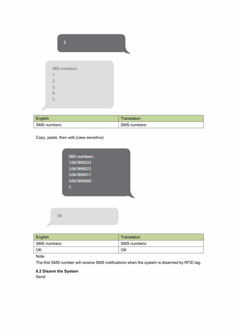
English Translation
SMS numbers: SMS numbers:
Copy, paste, then edit (case sensitive):
English Translation
SMS numbers: SMS numbers:
OK OK
Note
The first SMS number will receive SMS notifications when the system is disarmed by RFID tag.
8.2 Disarm the System
Send:

English Translation
System disarmed. System disarmed.
Arm the System
Send:
English Translation
System armed. System armed.
Home Mode
Send:
English Translation
System in home mode. System in home mode.

8.3 Settings Enquiry
Send:
English Translation
System: Disarmed
AC power: on
System: Disarmed
AC power: on
Note
The values indicated hereinabove will change after having set up the system.
8.4 Store Phone Numbers
Send:
English Translation
Phone numbers: Phone numbers:
Copy, paste, then edit (case sensitive):
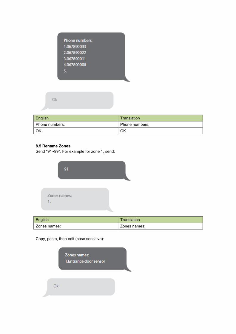
English Translation
Phone numbers: Phone numbers:
OK OK
8.5 Rename Zones
Send "91~99". For example for zone 1, send:
English Translation
Zones names: Zones names:
Copy, paste, then edit (case sensitive):
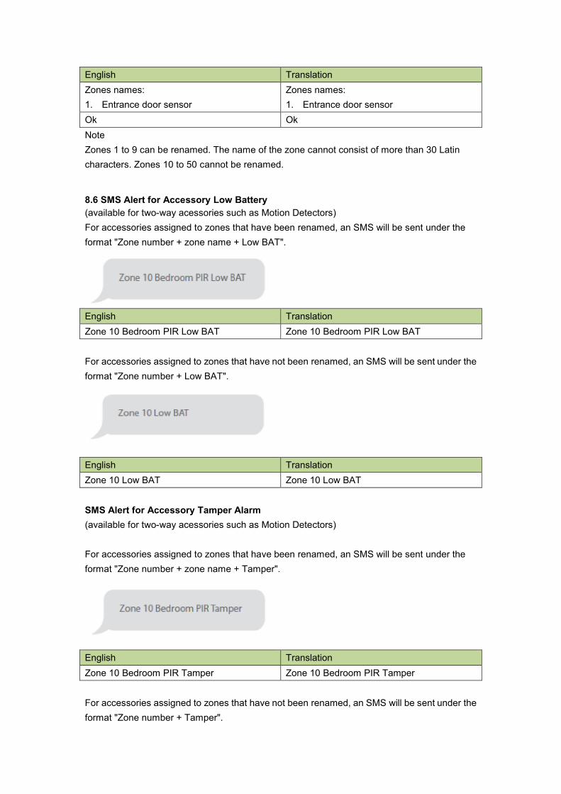
English Translation
Zones names:
1. Entrance door sensor
Zones names:
1. Entrance door sensor
Ok Ok
Note
Zones 1 to 9 can be renamed. The name of the zone cannot consist of more than 30 Latin
characters. Zones 10 to 50 cannot be renamed.
8.6 SMS Alert for Accessory Low Battery
(available for two-way acessories such as Motion Detectors)
For accessories assigned to zones that have been renamed, an SMS will be sent under the
format "Zone number + zone name + Low BAT".
English Translation
Zone 10 Bedroom PIR Low BAT Zone 10 Bedroom PIR Low BAT
For accessories assigned to zones that have not been renamed, an SMS will be sent under the
format "Zone number + Low BAT".
English Translation
Zone 10 Low BAT Zone 10 Low BAT
SMS Alert for Accessory Tamper Alarm
(available for two-way acessories such as Motion Detectors)
For accessories assigned to zones that have been renamed, an SMS will be sent under the
format "Zone number + zone name + Tamper".
English Translation
Zone 10 Bedroom PIR Tamper Zone 10 Bedroom PIR Tamper
For accessories assigned to zones that have not been renamed, an SMS will be sent under the
format "Zone number + Tamper".
English Translation
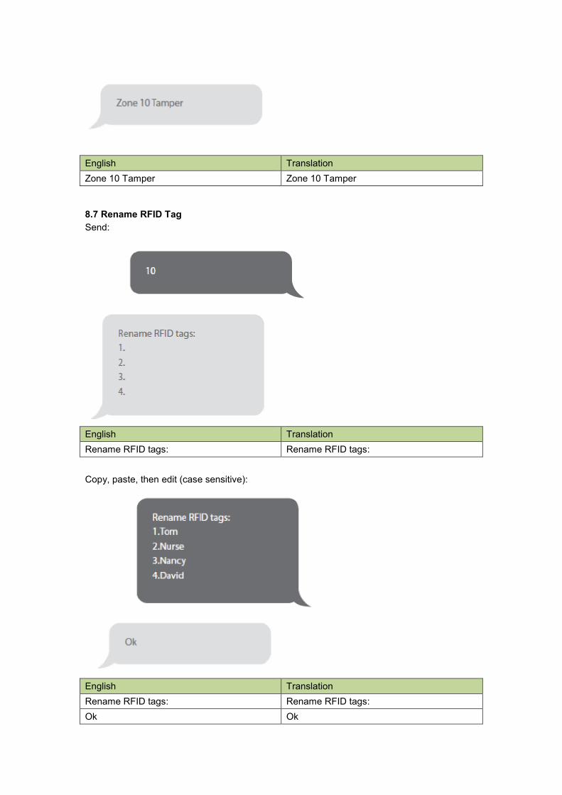
Zone 10 Tamper Zone 10 Tamper
8.7 Rename RFID Tag
Send:
English Translation
Rename RFID tags: Rename RFID tags:
Copy, paste, then edit (case sensitive):
English Translation
Rename RFID tags: Rename RFID tags:
Ok Ok

Note
The first SMS number will receive SMS notifications when the system is disarmed by RFID
tag.
If the RFID tag that disarms the system has been renamed, the SMS notification will be "Tag
01 Tag name Disarm". ("01" is the number of the tag)
Other tags will be attributed a number based on the order of registration to the control panel;
the SMS notifications will in such case be "Tag-04 Disarm" ("04" is the number of the tag).
Refer to the instructions on page 13 to learn how to register an RFID tag in the control panel.
8.8 Entry and Exit Delay Time
Send:
English Translation
Entry delay time(0-300sec):0
Exit delay time(0-300sec):0
Entry delay time(0-300sec):0
Exit delay time(0-300sec):0
Copy, paste, then edit (case sensitive):
English Translation
Entry delay time(0-300sec):10
Exit delay time(0-300sec):20
Entry delay time(0-300sec):10
Exit delay time(0-300sec):20
OK OK
Note
This function will only affect detectors assigned to the Delay zone. Refer to the instructions on
page 14 of this manual to learn how to set up your sensor to the Delay zone.
This function can be used if you do not want to bring a remote control or a RFID tag with you.
When you arm the system, the system will be armed after the delay set. When you disarm the
system, the system will be disarmed after the delay set.
When arming the system, you hear one beep every second to remind you to leave.
The beep rhythm speeds up during the last 10 seconds. If an intruder is detected, the alarm
will be delayed accordingly.
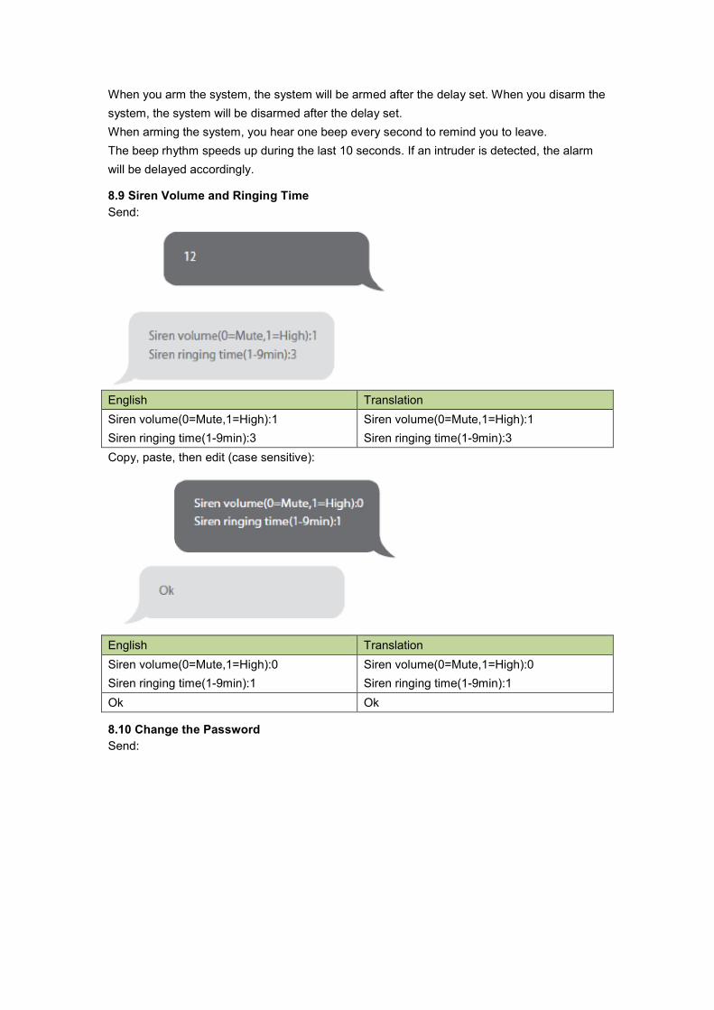
8.9 Siren Volume and Ringing Time
Send:
English Translation
Siren volume(0=Mute,1=High):1
Siren ringing time(1-9min):3
Siren volume(0=Mute,1=High):1
Siren ringing time(1-9min):3
Copy, paste, then edit (case sensitive):
English Translation
Siren volume(0=Mute,1=High):0
Siren ringing time(1-9min):1
Siren volume(0=Mute,1=High):0
Siren ringing time(1-9min):1
Ok Ok
8.10 Change the Password
Send:

English Translation
Disarm password (4 digits):
1234
Disarm password (4 digits):
1234
Copy, paste, then edit (case sensitive):
English Translation
Disarm password (4 digits):
8888
Disarm password (4 digits):
8888
OK OK
DEFAULT PASSWORD: 1234
8.11 Change System Language
Send the code corresponding to the language you want to set. For example, for English, send
"0001".
Refer to the table below for the full list of language codes:
0001 English
0002 French
0008 German
0009 Spanish

0004 Danish
0005 Dutch
0006 Italian
0007 Swedish
0010 Finnish
0011 Norwegian
0014 Portuguese
0015 Polish
Languages available may vary depending on the version of your product.
8.12 Restore System to Factory Settings by SMS
Send:
The settings will be restored to default values. Stored phone numbers and connected
accessories will also be deleted.
Note
Only stored numbers can send the SMS to restore factory settings.
Hard Reset
Turn the control panel on (if the control panel is already on, turn it off and turn it on again).
Press the tamper switch at the back of the control panel 5 times within 5 seconds after having
turned it on. You have to take off the plastic plate that pushes the tamper switch in order to do
so.
Settings will be restored to default values.
Stored phone numbers and connected accessories will be cleared.
9. FAQ
Issue Cause of malfunction Solution
No response following
interaction with the
control panel
The control panel is switched
off
Open the battery compartment and
turn the power on
Electricity grid failure Contact your electricity provider
Backup batteries are empty Plug the AC adapter to an AC
socket
Accessories cannot
connect to the control
panel
The control panel is not in
Connection mode
Make sure the control panel is in
Connection mode
Accessories have not been
triggered for connection
Make sure the accessory is
triggered so to send a signal to the
control panel
When attempting the The accessory has already been
connection, the control panel
beeps twice
connected
Make sure you do not trigger any
other accessory when connecting
one accessory to the control panel
(e.g. do not stay in the detection
scope of a motion detector if it is not
the one you want to connect)
No response from the
control panel following
commands from the
remote control
The remote control has not
been connected to the control
panel
Follow the instructions on point
3.2.1 of this manual to connect the
remote control to the panel
Remote control is too far from
the control panel
Transmission distance of the
remote control: 80 m (in open area)
remote control A signal repeater can be installed to
increase the transmission distance
RFID tag fails to disarm
the system
RFID tag has not been
connected to the control panel
Follow the instructions on point
3.2.4 of this manual to connect the
RFID tag to the control panel
If you are experiencing issues that are not described in the FAQ above, visit
denver-electronics.com to download the latest update of this user manual and for additional
support.
10. STANDARDS
ALL RIGHTS RESERVED, COPYRIGHT DENVER ELECTRONICS A/S
Electric and electronic equipment and included batteries contains materials, components and
substances that can be hazardous to your health and the environment, if the waste material
(discarded electric and electronic equipment and batteries) is not handled correctly.
Electric and electronic equipment and batteries is marked with the crossed out trash can
symbol, seen below. This symbol signifies that electric and electronic equipment and batteries
should not be disposed of with other household waste, but should be disposed of separately.
As the end user it is important that you submit your used batteries to the approriate and
designated facility. In this manner you make sure that the batteries are recycled in accordance
with legislature and will not harm the environment.
All cities have established collection points, where electric and electronic equipment and
batteries can either be submitted free of charge at recycling stations and other collection sites,
or be collected from the households. Additional information is available at the technical
department of your city.
Imported by:
DENVER ELECTRONICS A/S
Stavneagervej 22
DK-8250 Egaa
Denmark
www.facebook.com/denverelectronics
Hereby, Inter Sales A/S, declares that this product (HSA-120) is in compliance with the
essential requirements and other relevant provisions of Directive 1999/5/EC. A copy of the
Declaration of conformity may be obtained at:
Inter Sales A/S
Stavneagervej 22,
DK-8250 Egaa
Denmark