Embed Size (px)
Citation preview
AA4PG 3/30/2013 [email protected] Page 1 of 14
Dentron MLA-2500 GI-7B Conversion Based on W4ZT, W4EMF, K4POZ
Conversions
This is yet one more Dentron MLA-2500 conversion. By and large this one follows the steps
outlined by W4ZT, W4EMF, and K4POZ and their work is gratefully acknowledged. In addition, I have
made a few changes that may be helpful to others going down this same road. These changes are
explained below. This will probably be easier to follow with a printout of the W4ZT et al. schematic at
your side. The schematic is available at http://gi7b.com/mla2500/mla2500mod.pdf
MLA-2500 GI-7B Tube Sockets using 8875 Holes
The first change was to use the original 8875 socket holes. The K4POZ sockets are excellent and
can be used with the original chassis. Here are the steps after removing the 8875 sockets.
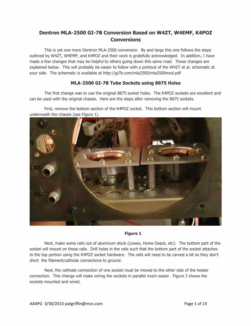
First, remove the bottom section of the K4POZ socket. This bottom section will mount
underneath the chassis (see Figure 1).
Figure 1
Next, make some rails out of aluminum stock (Lowes, Home Depot, etc). The bottom part of the
socket will mount on these rails. Drill holes in the rails such that the bottom part of the socket attaches
to the top portion using the K4POZ socket hardware. The rails will need to be carved a bit so they don’t
short the filament/cathode connections to ground.
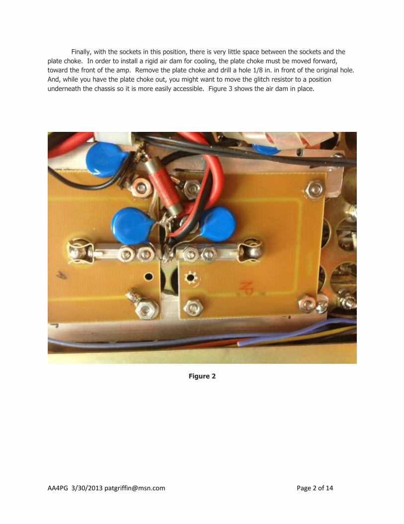
Next, the cathode connection of one socket must be moved to the other side of the heater
connection. This change will make wiring the sockets in parallel much easier. Figure 2 shows the
sockets mounted and wired.
AA4PG 3/30/2013 [email protected] Page 2 of 14
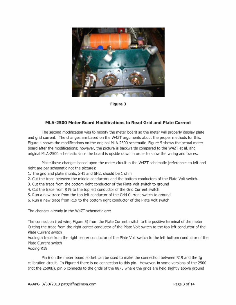
Finally, with the sockets in this position, there is very little space between the sockets and the
plate choke. In order to install a rigid air dam for cooling, the plate choke must be moved forward,
toward the front of the amp. Remove the plate choke and drill a hole 1/8 in. in front of the original hole.
And, while you have the plate choke out, you might want to move the glitch resistor to a position
underneath the chassis so it is more easily accessible. Figure 3 shows the air dam in place.
Figure 2
AA4PG 3/30/2013 [email protected] Page 3 of 14
Figure 3
MLA-2500 Meter Board Modifications to Read Grid and Plate Current
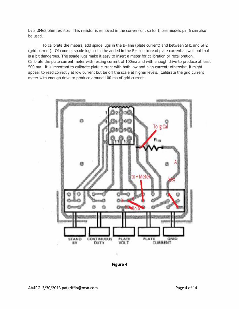
The second modification was to modify the meter board so the meter will properly display plate
and grid current. The changes are based on the W4ZT arguments about the proper methods for this.
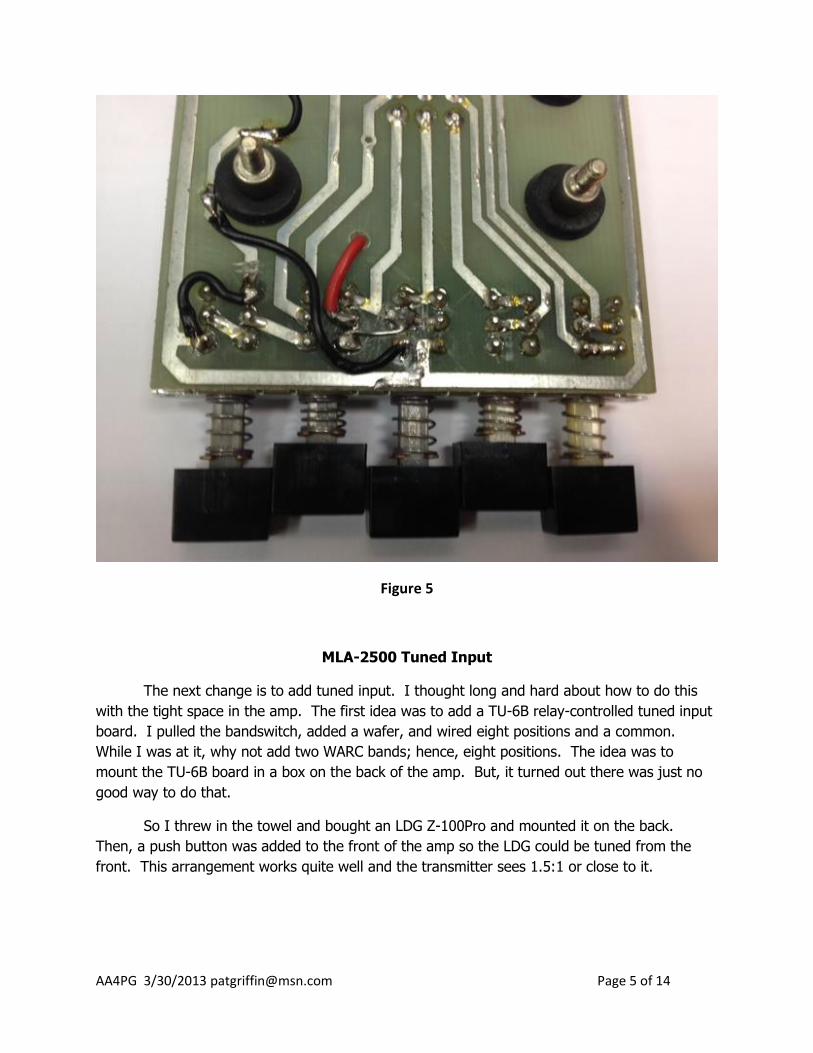
Figure 4 shows the modifications on the original MLA-2500 schematic. Figure 5 shows the actual meter
board after the modifications; however, the picture is backwards compared to the W4ZT et al. and
original MLA-2500 schematic since the board is upside down in order to show the wiring and traces.
Make these changes based upon the meter circuit in the W4ZT schematic (references to left and
right are per schematic not the picture):
1. The grid and plate shunts, SH1 and SH2, should be 1 ohm
2. Cut the trace between the middle conductors and the bottom conductors of the Plate Volt switch.
3. Cut the trace from the bottom right conductor of the Plate Volt switch to ground
4. Cut the trace from R19 to the top left conductor of the Grid Current switch
5. Run a new trace from the top left conductor of the Grid Current switch to ground
6. Run a new trace from R19 to the bottom right conductor of the Plate Volt switch
The changes already in the W4ZT schematic are:
The connection (red wire, Figure 5) from the Plate Current switch to the positive terminal of the meter
Cutting the trace from the right center conductor of the Plate Volt switch to the top left conductor of the
Plate Current switch
Adding a trace from the right center conductor of the Plate Volt switch to the left bottom conductor of the
Plate Current switch
Adding R19
Pin 6 on the meter board socket can be used to make the connection between R19 and the Ig
calibration circuit. In Figure 4 there is no connection to this pin. However, in some versions of the 2500
(not the 2500B), pin 6 connects to the grids of the 8875 where the grids are held slightly above ground
AA4PG 3/30/2013 [email protected] Page 4 of 14
by a .0462 ohm resistor. This resistor is removed in the conversion, so for those models pin 6 can also
be used.
To calibrate the meters, add spade lugs in the B- line (plate current) and between SH1 and SH2
(grid current). Of course, spade lugs could be added in the B+ line to read plate current as well but that
is a bit dangerous. The spade lugs make it easy to insert a meter for calibration or recalibration.
Calibrate the plate current meter with resting current of 100ma and with enough drive to produce at least
500 ma. It is important to calibrate plate current with both low and high current; otherwise, it might
appear to read correctly at low current but be off the scale at higher levels. Calibrate the grid current
meter with enough drive to produce around 100 ma of grid current.
Figure 4
AA4PG 3/30/2013 [email protected] Page 5 of 14
Figure 5
MLA-2500 Tuned Input
The next change is to add tuned input. I thought long and hard about how to do this
with the tight space in the amp. The first idea was to add a TU-6B relay-controlled tuned input
board. I pulled the bandswitch, added a wafer, and wired eight positions and a common.
While I was at it, why not add two WARC bands; hence, eight positions. The idea was to
mount the TU-6B board in a box on the back of the amp. But, it turned out there was just no
good way to do that.
So I threw in the towel and bought an LDG Z-100Pro and mounted it on the back.
Then, a push button was added to the front of the amp so the LDG could be tuned from the
front. This arrangement works quite well and the transmitter sees 1.5:1 or close to it.
AA4PG 3/30/2013 [email protected] Page 6 of 14
40 and 80 Meter Pi Net Modification
Even though the amp tuned on 40 meters it wasn’t ideal. Maximum output occurred
with the Load capacitor almost fully meshed. A 100pf, 7.5kv fixed, doorknob capacitor was
added in parallel with C42 (100pf, 7kv but mislabeled as C41, line 17 in parts list). This
additional capacitance changed the maximum output position to more acceptable, midrange
settings of the Load capacitor. A 100pf, 7.5kv capacitor was also added in parallel with C46,
the 80-meter fixed, load capacitor. The tuning was improved similarly.
160 Meter Pi Net Modification
Maximum output on 160 occurred with the Tune capacitor fully meshed. The fix for this
was a bit different and was determined experimentally, or we used to say, by “Easter egging.”
The final solution was to add a 45pf, 7.5kv fixed, doorknob capacitor in parallel with C9. In my
unit C9 is a 100pf and a 200pf capacitor in parallel. These are the fixed capacitors in parallel
with the Tune variable capacitor. With this change, maximum output occurred about 1/8 in
short of full mesh. In a second conversion, the amp had 3, 100pf caps for C9. And, the
additional cap required to pull the tuning into range was 24.8 pf.
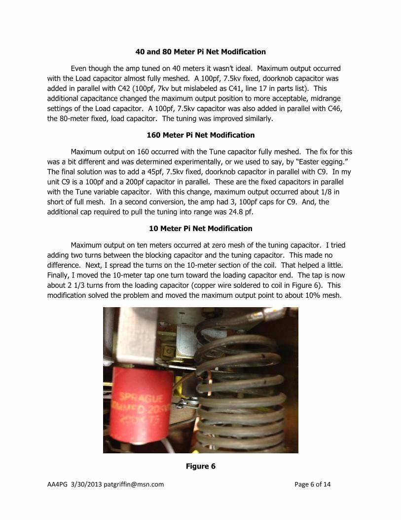
10 Meter Pi Net Modification
Maximum output on ten meters occurred at zero mesh of the tuning capacitor. I tried
adding two turns between the blocking capacitor and the tuning capacitor. This made no
difference. Next, I spread the turns on the 10-meter section of the coil. That helped a little.
Finally, I moved the 10-meter tap one turn toward the loading capacitor end. The tap is now
about 2 1/3 turns from the loading capacitor (copper wire soldered to coil in Figure 6). This
modification solved the problem and moved the maximum output point to about 10% mesh.
Figure 6
AA4PG 3/30/2013 [email protected] Page 7 of 14
Power Supply Capacitors and New Filament Transformer
The preceding describes the first Dentron conversion. I came across another tubeless
2500 and couldn’t resist. The following describes a few changes in this second conversion.
The GI-7B tubes have 12.6 volt filaments so a filament transformer has to be somehow
shoehorned into the amplifier. The most common way to do this is to replace the high voltage
filter capacitors with modern, shorter ones. This change creates enough room in the power
supply section to mount the new transformer; besides, after all these years they probably need
replacing.
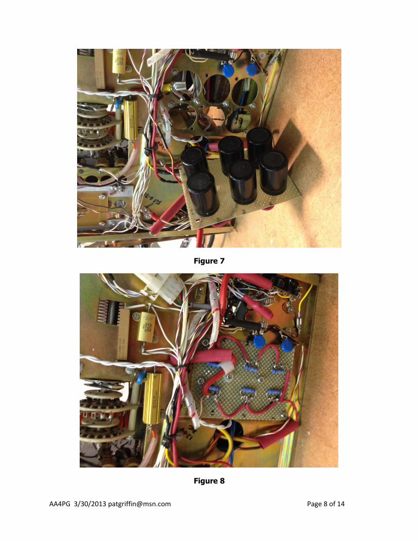
For the first conversion, I mounted the capacitors on a vertical perf board and mounted
the transformer vertically on the chassis. However, for the second conversion, I believe I have
found a better way. Figure 7 shows the new caps mounted on a perf board ready for
installation. The board is bolted to the bottom of the chassis such that the caps fit in the holes
left by the removed caps. The connections are made with spade, quick-release connectors.
With this arrangement, it is pretty easy to remove the caps if that becomes necessary. Figure 8
shows the board in place.
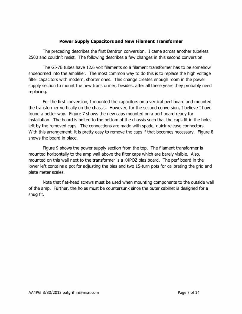
Figure 9 shows the power supply section from the top. The filament transformer is
mounted horizontally to the amp wall above the filter caps which are barely visible. Also,
mounted on this wall next to the transformer is a K4POZ bias board. The perf board in the
lower left contains a pot for adjusting the bias and two 15-turn pots for calibrating the grid and
plate meter scales.
Note that flat-head screws must be used when mounting components to the outside wall
of the amp. Further, the holes must be countersunk since the outer cabinet is designed for a
snug fit.
AA4PG 3/30/2013 [email protected] Page 9 of 14
Figure 9
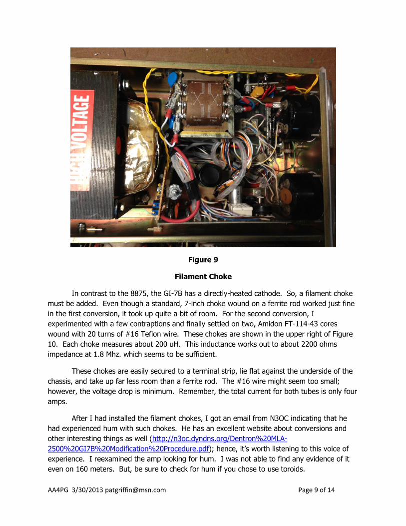
Filament Choke
In contrast to the 8875, the GI-7B has a directly-heated cathode. So, a filament choke
must be added. Even though a standard, 7-inch choke wound on a ferrite rod worked just fine
in the first conversion, it took up quite a bit of room. For the second conversion, I
experimented with a few contraptions and finally settled on two, Amidon FT-114-43 cores
wound with 20 turns of #16 Teflon wire. These chokes are shown in the upper right of Figure
10. Each choke measures about 200 uH. This inductance works out to about 2200 ohms
impedance at 1.8 Mhz. which seems to be sufficient.
These chokes are easily secured to a terminal strip, lie flat against the underside of the
chassis, and take up far less room than a ferrite rod. The #16 wire might seem too small;
however, the voltage drop is minimum. Remember, the total current for both tubes is only four
amps.
After I had installed the filament chokes, I got an email from N3OC indicating that he
had experienced hum with such chokes. He has an excellent website about conversions and
other interesting things as well (http://n3oc.dyndns.org/Dentron%20MLA-
2500%20GI7B%20Modification%20Procedure.pdf); hence, it’s worth listening to this voice of
experience. I reexamined the amp looking for hum. I was not able to find any evidence of it
even on 160 meters. But, be sure to check for hum if you chose to use toroids.
AA4PG 3/30/2013 [email protected] Page 10 of 14
Figure 10
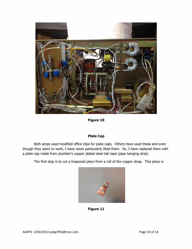
Plate Cap
Both amps used modified office clips for plate caps. Others have used these and even
though they seem to work, I have never particularly liked them. So, I have replaced them with
a plate cap made from plumber’s copper plated steel tab tape (pipe hanging strip).
The first step is to cut a trapezoid piece from a roll of the copper strap. This piece is
Figure 11
AA4PG 3/30/2013 [email protected] Page 11 of 14
about 1 ¼ in long and about 3/8 in wide at the small end (see Figure 11). Be sure the hole at
the small end is one of the large, 3/16 in, holes.
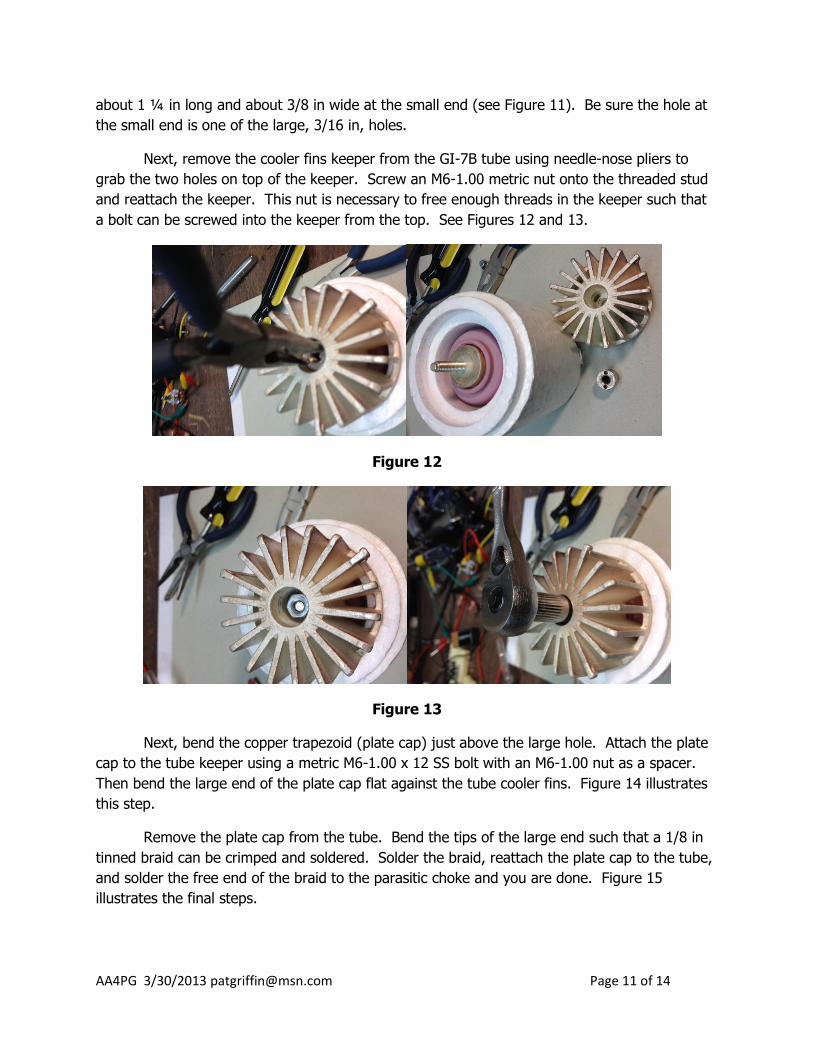
Next, remove the cooler fins keeper from the GI-7B tube using needle-nose pliers to
grab the two holes on top of the keeper. Screw an M6-1.00 metric nut onto the threaded stud
and reattach the keeper. This nut is necessary to free enough threads in the keeper such that
a bolt can be screwed into the keeper from the top. See Figures 12 and 13.
Figure 12
Figure 13
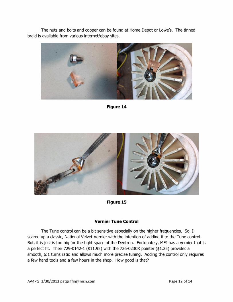
Next, bend the copper trapezoid (plate cap) just above the large hole. Attach the plate
cap to the tube keeper using a metric M6-1.00 x 12 SS bolt with an M6-1.00 nut as a spacer.
Then bend the large end of the plate cap flat against the tube cooler fins. Figure 14 illustrates
this step.
Remove the plate cap from the tube. Bend the tips of the large end such that a 1/8 in
tinned braid can be crimped and soldered. Solder the braid, reattach the plate cap to the tube,
and solder the free end of the braid to the parasitic choke and you are done. Figure 15
illustrates the final steps.
AA4PG 3/30/2013 [email protected] Page 12 of 14
The nuts and bolts and copper can be found at Home Depot or Lowe’s. The tinned
braid is available from various internet/ebay sites.
Figure 14
Figure 15
Vernier Tune Control
The Tune control can be a bit sensitive especially on the higher frequencies. So, I
scared up a classic, National Velvet Vernier with the intention of adding it to the Tune control.
But, it is just is too big for the tight space of the Dentron. Fortunately, MFJ has a vernier that is
a perfect fit. Their 729-0142-1 ($11.95) with the 726-0230R pointer ($1.25) provides a
smooth, 6:1 turns ratio and allows much more precise tuning. Adding the control only requires
a few hand tools and a few hours in the shop. How good is that?
AA4PG 3/30/2013 [email protected] Page 13 of 14
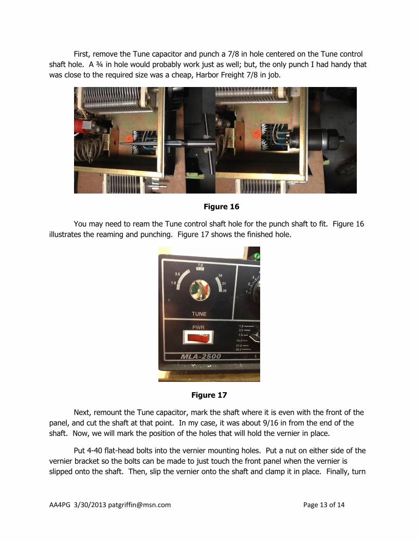
First, remove the Tune capacitor and punch a 7/8 in hole centered on the Tune control
shaft hole. A ¾ in hole would probably work just as well; but, the only punch I had handy that
was close to the required size was a cheap, Harbor Freight 7/8 in job.
Figure 16
You may need to ream the Tune control shaft hole for the punch shaft to fit. Figure 16
illustrates the reaming and punching. Figure 17 shows the finished hole.
Figure 17
Next, remount the Tune capacitor, mark the shaft where it is even with the front of the
panel, and cut the shaft at that point. In my case, it was about 9/16 in from the end of the
shaft. Now, we will mark the position of the holes that will hold the vernier in place.
Put 4-40 flat-head bolts into the vernier mounting holes. Put a nut on either side of the
vernier bracket so the bolts can be made to just touch the front panel when the vernier is
slipped onto the shaft. Then, slip the vernier onto the shaft and clamp it in place. Finally, turn
AA4PG 3/30/2013 [email protected] Page 14 of 14
the bolts back and forth to create indentions on the front panel that mark where the mounting
holes should be drilled. Figure 18 illustrates these steps.
Figure 18
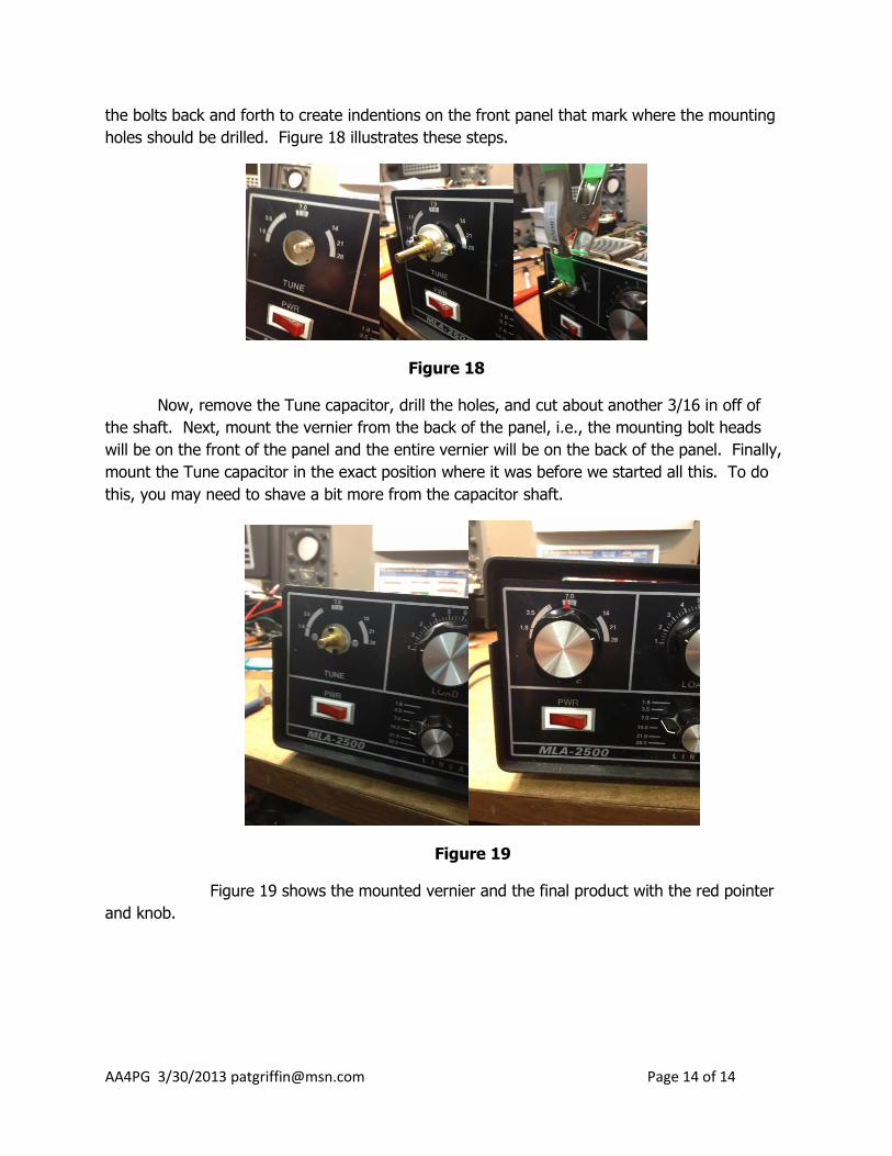
Now, remove the Tune capacitor, drill the holes, and cut about another 3/16 in off of
the shaft. Next, mount the vernier from the back of the panel, i.e., the mounting bolt heads
will be on the front of the panel and the entire vernier will be on the back of the panel. Finally,
mount the Tune capacitor in the exact position where it was before we started all this. To do
this, you may need to shave a bit more from the capacitor shaft.
Figure 19
Figure 19 shows the mounted vernier and the final product with the red pointer
and knob.