Embed Size (px)
Citation preview
Densification, Microstructure, and Wear Property of In SituTitanium Nitride-Reinforced Titanium Silicide Matrix CompositesPrepared by a Novel Selective Laser Melting Process
DONGDONG GU, CHEN HONG, and GUANGBIN MENG
This work presents the densification behavior, microstructural features, microhardness, andwear property of in situ TiN/Ti5Si3 composite parts prepared by a novel Selective Laser Melting(SLM) process. The occurrence of balling phenomenon at a low laser energy density combinedwith a high scan speed and the formation of thermal cracks at an excessive laser energy inputgenerally decreased densification rate. The in situ-formed TiN reinforcing phase experienced asuccessive morphological change: an irregular polyangular shape—a refined near-roundshape—a coarsened dendritic shape, as the applied laser energy density increased. The varia-tions in liquid-solid wettability and intensity of Marangoni convection within laser molten poolaccounted for the different growth mechanisms of TiN reinforcement. The TiN/Ti5Si3 com-posite parts prepared under the optimal SLM conditions had a near-full 97.7 pct theoreticaldensity and a uniform microhardness distribution with a significantly increased average value of1358.0HV0.3. The dry sliding wear tests revealed that a considerably low friction coefficient of0.19 without any apparent fluctuation and a reduced wear rate of 6.84 9 10�5mm3/Nm wereachieved. The enhanced wear resistance was attributed to the formation of adherent strain-hardened tribolayer covered on the worn surface.
DOI: 10.1007/s11661-011-0876-8� The Minerals, Metals & Materials Society and ASM International 2011
I. INTRODUCTION
THE titanium silicide Ti5Si3 intermetallic compoundhas been considered recently as a promising candidatematerial for high-temperature structural applicationsbecause of its high melting temperature [2403 K(2130 �C)], relatively low density (4.32 g/cm3), capacityto retain high strength up to 1473 K (1200 �C), andexcellent oxidation and creep resistance.[1,2] Neverthe-less, because of its complex hexagonal crystal structurewith a low symmetry (D88), the monolithic Ti5Si3 has aconsiderably low fracture toughness at ambient temper-ature.[3] Thus, a major challenge for a successfulapplication of Ti5Si3 material is to reduce its room-temperature brittleness. In this respect, the existing workby Wang et al.,[4] Shon et al.,[5] and Li et al.[6] ascer-tained that the preparation of ceramic-reinforced Ti5Si3-based composites by incorporating the stiffer ceramicphase within Ti5Si3 matrix is an important method to
improve the integrated mechanical properties includingfracture toughness. In particular, the development ofnovel in situ composites, in which the ceramic reinforce-ments are synthesized in the metallic matrix by chemicalreactions between elements, exhibits more significantadvantages, e.g., the refined microstructural scale ofin situ formed reinforcements, the clean reinforcement/matrix interfaces with stronger interfacial bonding, andthe increased thermodynamic stability and mechanicalproperties of the composites.[7] In contrast, a reasonableselection of the ceramic reinforcement that is feasible forTi5Si3 matrix is required. It is known that the coefficientof thermal expansion (CTE) and the elastic modulus aretwo most important material properties that determinethe level of residual stress in composites.[8] Based on theprevious studies,[1,2,9] the TiC has been demonstrated tobe a suitable candidate material used as the reinforce-ment for Ti5Si3-based composites because of the similarCTEs (Ti5Si3 9.7 9 10�7/K vs TiC 7.7 9 10�7/K). TheTiN, which has almost the same CTE (9.4 9 10�7/K) asthat of Ti5Si3, matches even better with Ti5Si3 matrix.Furthermore, the elastic modulus of TiN (250.37 GPa)is considerably lower than that of TiC (439.43 GPa),[10]
and normally, the stress of composites can be controlledby using material with a low elastic modulus.[8] There-fore, the TiN can be regarded as a more promisingceramic reinforcement for Ti5Si3.Bulk-form composites containing the in situ formed
reinforcements normally are prepared by conventionalmethods including powder metallurgy (PM),[11,12] self-propagating high-temperature synthesis,[13–15] and cast-ing.[16,17] However, the production of composites by
DONGDONG GU, Professor and Alexander von HumboldtResearch Fellow, is with the College of Materials Science andTechnology, Nanjing University of Aeronautics and Astronautics,210016 Nanjing, People’s Republic of China, and is also with theFraunhofer Institute for Laser Technology ILT/Chair for LaserTechnology LLT, RWTH Aachen, D-52074 Aachen, Germany.Contact e-mail: [email protected] CHEN HONG, PhDCandidate, is with the Fraunhofer Institute for Laser TechnologyILT/Chair for Laser Technology LLT, RWTH Aachen. GUANGBINMENG, Graduate Student, is with the College of Materials Scienceand Technology, Nanjing University of Aeronautics and Astronautics.
Manuscript submitted March 13, 2011.Article published online September 15, 2011
METALLURGICAL AND MATERIALS TRANSACTIONS A VOLUME 43A, FEBRUARY 2012—697
these conventional processes is prone to generate largeagglomerates of reinforcing phases, thereby decreasingthe microstructural homogeneity and resultant mechan-ical properties. Furthermore, the high-temperatureceramic reinforcing phases typically remain in particlemorphology in the conventional composites because theworkable processing temperature normally cannotincrease above the melting points of ceramics. Theincorporation of the solid ceramic particles within thematrix, however, tends to induce the formation ofinterfacial microcracks because of the limited wettingcharacteristics between ceramics and metals. In contrast,the conventional processes, which generally need expen-sive and dedicated tools such as molds or dies, are notsuitable for small-volume production and complexshapes. The complicated preprocessing and postprocess-ing steps necessary in conventional routes make them atime-consuming process. The probability of the forma-tion of process defects also increases during the longcycle time. Therefore, novel processing methods arehighly required for the direct net-shape fabrication ofcomplex-shaped ceramic reinforced composite compo-nents with favorable microstructural and mechanicalproperties.
Selective laser melting (SLM), as a newly developedrapid prototyping (RP) technique,[18–22] has the capa-bility to fabricate three-dimensional parts with anycomplex configurations directly from powder materi-als.[23–26] SLM creates fully dense parts in a layer-by-layer manner by selectively fusing and consolidatingthin layers of loose powder using a high-energy laser beam,without any postprocessing requirements. Recently,some preliminary research[27,28] focused on the prepara-tion of in situ composite parts using the SLM process,considering its flexibility in feedstock and shapes.Nevertheless, because of the complex metallurgicalnature of in situ SLM system, which involves bothchemical reactions and multiple modes of heat, mass,and momentum transfer, SLM-processed compositesmay suffer from processing problems such as gasentrapment, aggregation of reinforcements, residualstresses, and interfacial microcracks. Furthermore,SLM is performed based on a complete melting/solid-ification mechanism, and accordingly, the high-melting-point ceramic reinforcing phases are formed through adissolution/precipitation manner. Different to the par-ticle morphology before melting, the in situ formedceramic crystals may have versatile growth morpholo-gies in the finally solidified structures. Therefore, theunpredictability and/or uncontrollability of the forma-tion of in situ phases and microstructures in a SLMroute are still a major challenge. As the microstructuralfeatures of laser-processed powder may influence theattendant mechanical properties significantly, a detailedunderstanding of the crystallization mechanism andmicrostructural development of the in situ phases isrequired.
In the current work, SLM of Si3N4/Ti powder systemwas performed to prepare bulk-form TiN/Ti5Si3 in situcomposites. The evolutions of phases and microstruc-tures of SLM-processed composites under different laserprocessing parameters were studied and the mechanical
properties such as densification rate, microhardness, andwear property were assessed. The predominant metal-lurgical mechanisms responsible for the variationsin microstructural and mechanical properties weredisclosed.
II. EXPERIMENTAL PROCEDURE
A. Powder Preparation
The 99.9 pct purity Ti powder with a polyangularstructure and an average particle size of 30 lm and the99.5 pct purity Si3N4 powder with an irregular shapeand a mean particle size of 4 lm were used as thestarting materials. According to the Si3N4:Ti weightratio of 24.55:75.45 (i.e., the equivalent mol ratio of 1:9),the two components were milled using a high-energyPulverisette 6 planetary mono-mill (Fritsch GmbH,Idar-Oberstein, Germany). Stainless steel grinding ballsand the powder mixture to be treated were charged intothe grinding bowl, with the ball-to-powder weight ratioof 10:1. High-purity argon was used as the protectivegas. The milling time and the rotation speed of the maindisk were settled at 8 hours and 250 rpm, respectively.To avoid the excessive temperature increase within thegrinding bowl, ball milling duration of 20 minutes wasfollowed by an interval of 10 minutes. Details concern-ing powder preparation have been addressed in theliterature.[29] The as-milled composite powder had anear-spherical shape and a refined particle size of 8 to22 lm.
B. Laser Processing
The SLM apparatus, as illustrated schematically inFigure 1(a), consisted mainly of a 2000 SM continuouswave Gaussian CO2 laser (k = 10.6 lm) with a maxi-mum output power of 5 kW and a focused spot size atthe substrate surface of 0.3 mm (Rofin-Sinar LaserGmbH, Hamburg, Germany), an automatic powderlayering system with a roller, a computer system forprocess control, and an inert argon gas protectionsystem. As the parts were to be prepared, a titaniumsubstrate was placed primarily on the building platformand leveled. A thin layer of the milled powder (0.1 mmin thickness) was then deposited on the substrate by theroller. Subsequently, the laser beam scanned the powderbed surface to form layer-wise profiles according to thecomputer-aided design data of the parts. A simple linearraster scan pattern was used (Figure 1(b)) with a scanline spacing of 0.15 mm. The similar process wasrepeated in a layer-by-layer manner until multilayerparts with dimensions of 8 mm 9 8 mm 9 6 mm werefinished. Through a series of preliminary SLM experi-ments, the laser power was optimized at 1 kW. Mean-while, the scan speeds were settled periodically at 0.1,0.2, 0.3, and 0.4 m/s by the SLM control program. Fourdifferent ‘‘linear laser energy densities’’ (g) of 10, 5, 3.33,and 2.5 kJ/m, which was defined by the ratio of laserpower to scan speed,[30] were used to estimate the laserenergy input to the powder layer being treated.
698—VOLUME 43A, FEBRUARY 2012 METALLURGICAL AND MATERIALS TRANSACTIONS A

C. Microstructural Characterization
Phase identification was performed by a D8 AdvanceX-ray diffractometer (XRD) (Bruker AXS GmbH,Germany) with Cu Ka radiation at 40 kV and 40 mA,using a continuous scan mode. A quick scan at 4 deg/min was performed primarily over a wide range of2h = 30 to 80 deg. A slower scan rate of 1 deg/min wasused over 2h = 34.0 to 36.0 deg and 2h = 39.0 to41.0 deg to give a more accurate determination ofdiffraction peaks. Samples for metallographic examina-tions were cut, ground, and polished according tostandard procedures and were etched with a solutionconsisting of HF (4 mL), HNO3 (6 mL), and distilledwater (100 mL) for 45 seconds. The microstructureswere characterized using a Quanta 200 scanning electronmicroscope (SEM) (FEI Company, Hillsboro, OR) in asecondary electron mode at an accelerating voltage of20 kV. A UTHSCSA ImageTool 3.0 image processingand analysis program was used to acquire the sizes ofreinforcing particles. Chemical compositions were deter-mined by an EDAX Genesis energy dispersive X-ray
(EDX) spectroscope (EDAX Inc., Mahwah, NJ), usinga super-ultra thin window sapphire detector.
D. Mechanical Properties Testing
The density (q) of SLM-processed samples wasmeasured based on the Archimedes principle. TheVickers hardness was determined using a MicroMet5101 microhardness tester (Buehler GmbH, Dusseldorf,Germany) at a load of 0.3 kg and an indentation time of15 seconds. Dry sliding wear tests were conducted in aHT-500 ball-on-disk tribometer (Lanzhou ZhongKeKaiHua Sci. & Technol. Co., Ltd., Lanzhou, China) inair at room temperature. The surfaces of the specimenswere ground and polished prior to wear tests. A bearingsteel GCr15 ball with a diameter of 3 mm and a meanhardness of HRC60 was taken as the counterfacematerial and a test load of 3N was applied. The frictionunit was rotated at a speed of 560 rpm for 30 minutesand the rotation radius was fixed at 2 mm. The frictioncoefficients of the specimens were recorded during weartests. The wear volume (V) was determined gravimetri-cally using V = Mloss/q, whereMloss was the weight lossof the specimens after wear tests. The wear rate (x) wascalculated by x = V/(WL), where W was the contactload and L was the sliding distance.
III. RESULTS AND DISCUSSION
A. Phases
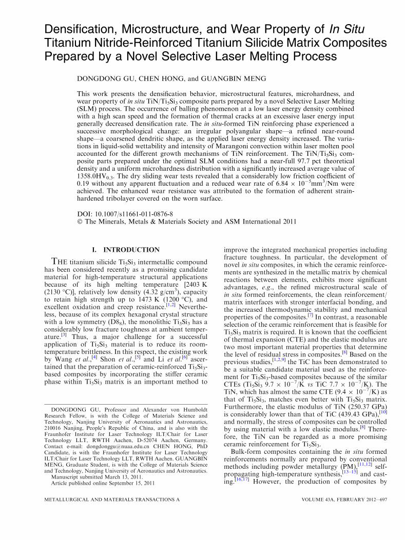
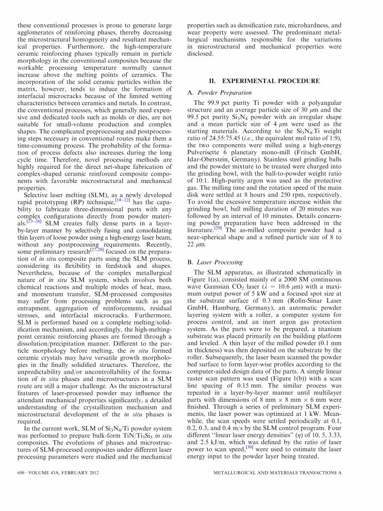
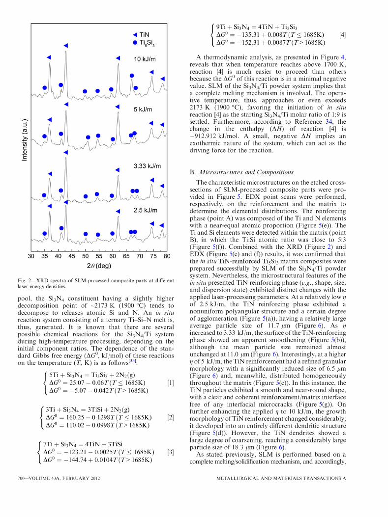
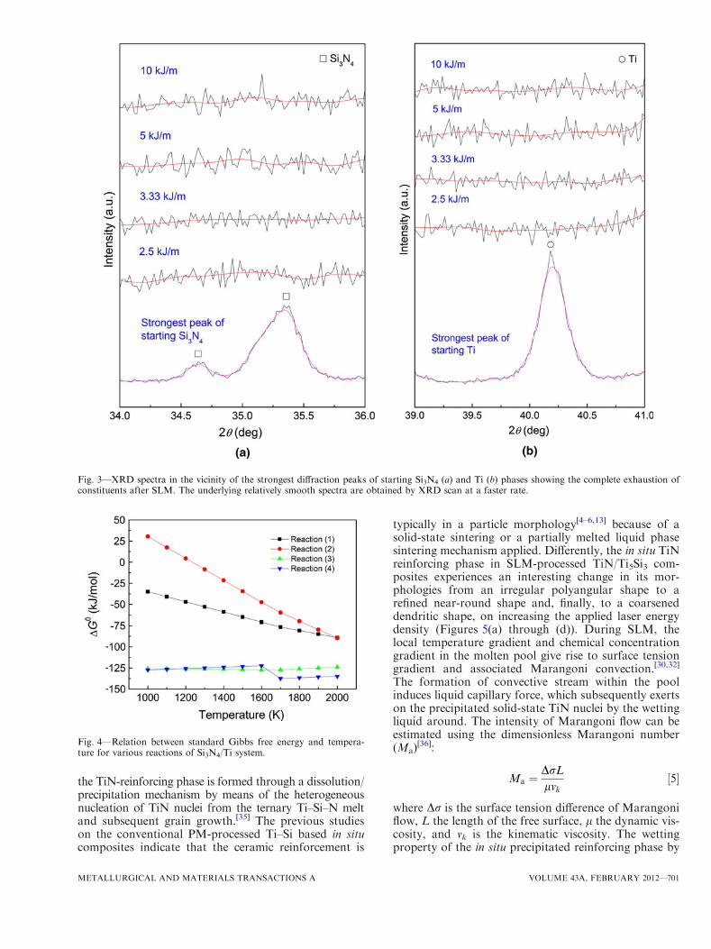
Figure 2 depicted the typical XRD patterns of SLM-processed composite parts. The strong diffraction peakscorresponding to TiN (based on JCPDS Card No.87-0632) and Ti5Si3 (based on JCPDS Card No. 29-1362)phases were generally identified in SLM-processed partsat different laser energy input. To reveal the reactionbehaviors of the Si3N4 and Ti constituents in the startingcomposite powder, a more accurate XRD scan at arelatively low rate was performed in the vicinity of thestrongest diffraction peaks of Si3N4 (2h = 35.344 deg)and Ti (2h = 40.161 deg), as illustrated in Figure 3. Itwas observed that the initial Si3N4 and Ti diffractionpeaks disappeared completely in all SLM-processedparts. Therefore, it was reasonable to conclude that forthe given laser energy densities of 2.5 to 10 kJ/m, SLMprocessing of Si3N4/Ti powder system generally led tothe in situ formation of TiN/Ti5Si3 composites free ofany residual impurity phases.When the high-energy laser beam scans over the
powder layer, the energy is absorbed directly by thepowder through both bulk coupling and powder cou-pling mechanisms,[31] thereby realizing the thermaliza-tion of the absorbed laser energy. The Si3N4/Ti powderparticles are heated up speedily, typically within aconsiderably short timescale below 4 ms,[32] leading tothe complete melting of Ti constituent as the operativetemperature reaches its melting point [~1943 K(1670 �C)]. Because of a considerably high thermaliza-tion caused by high-energy laser irradiation coupledwith the sufficient wetting of Ti liquid in the molten
Fig. 1—Schematics of SLM apparatus (a) and laser scanning pattern(b).
METALLURGICAL AND MATERIALS TRANSACTIONS A VOLUME 43A, FEBRUARY 2012—699
pool, the Si3N4 constituent having a slightly higherdecomposition point of ~2173 K (1900 �C) tends todecompose to releases atomic Si and N. An in situreaction system consisting of a ternary Ti–Si–N melt is,thus, generated. It is known that there are severalpossible chemical reactions for the Si3N4/Ti systemduring high-temperature processing, depending on theinitial component ratios. The dependence of the stan-dard Gibbs free energy (DG0, kJ/mol) of these reactionson the temperature (T, K) is as follows[33]:
5Tiþ Si3N4 ¼ Ti5Si3 þ 2N2ðg)DG0 ¼ 25:07� 0:06T ðT � 1685K)DG0 ¼ �5:07� 0:042T ðT>1685K)
8<
:½1�
3Tiþ Si3N4 ¼ 3TiSiþ 2N2ðg)DG0 ¼ 160:25� 0:1298T ðT � 1685K)DG0 ¼ 110:02� 0:0998T ðT>1685K)
8<
:½2�
7Tiþ Si3N4 ¼ 4TiNþ 3TiSiDG0 ¼ �123:21� 0:0025T ðT � 1685K)DG0 ¼ �144:74þ 0:0104T ðT>1685K)
8<
:½3�
9Tiþ Si3N4 ¼ 4TiNþ Ti5Si3DG0 ¼ �135:31þ 0:008T ðT � 1685K)DG0 ¼ �152:31þ 0:0087T ðT>1685K)
8<
:½4�
A thermodynamic analysis, as presented in Figure 4,reveals that when temperature reaches above 1700 K,reaction [4] is much easier to proceed than othersbecause the DG0 of this reaction is in a minimal negativevalue. SLM of the Si3N4/Ti powder system implies thata complete melting mechanism is involved. The opera-tive temperature, thus, approaches or even exceeds2173 K (1900 �C), favoring the initiation of in situreaction [4] as the starting Si3N4/Ti molar ratio of 1:9 issettled. Furthermore, according to Reference 34, thechange in the enthalpy (DH) of reaction [4] is�912.912 kJ/mol. A small, negative DH implies anexothermic nature of the system, which can act as thedriving force for the reaction.
B. Microstructures and Compositions
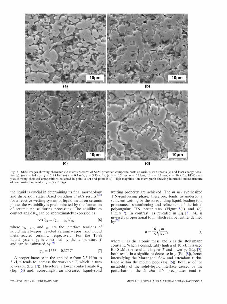
The characteristic microstructures on the etched cross-sections of SLM-processed composite parts were pro-vided in Figure 5. EDX point scans were performed,respectively, on the reinforcement and the matrix todetermine the elemental distributions. The reinforcingphase (point A) was composed of the Ti and N elementswith a near-equal atomic proportion (Figure 5(e)). TheTi and Si elements were detected within the matrix (pointB), in which the Ti:Si atomic ratio was close to 5:3(Figure 5(f)). Combined with the XRD (Figure 2) andEDX (Figure 5(e) and (f)) results, it was confirmed thatthe in situ TiN-reinforced Ti5Si3 matrix composites wereprepared successfully by SLM of the Si3N4/Ti powdersystem. Nevertheless, the microstructural features of thein situ presented TiN reinforcing phase (e.g., shape, size,and dispersion state) exhibited distinct changes with theapplied laser-processing parameters. At a relatively low gof 2.5 kJ/m, the TiN reinforcing phase exhibited anonuniform polyangular structure and a certain degreeof agglomeration (Figure 5(a)), having a relatively largeaverage particle size of 11.7 lm (Figure 6). As gincreased to 3.33 kJ/m, the surface of the TiN-reinforcingphase showed an apparent smoothening (Figure 5(b)),although the mean particle size remained almostunchanged at 11.0 lm (Figure 6). Interestingly, at a higherg of 5 kJ/m, the TiN reinforcement had a refined granularmorphology with a significantly reduced size of 6.5 lm(Figure 6) and, meanwhile, distributed homogeneouslythroughout the matrix (Figure 5(c)). In this instance, theTiN particles exhibited a smooth and near-round shape,with a clear and coherent reinforcement/matrix interfacefree of any interfacial microcracks (Figure 5(g)). Onfurther enhancing the applied g to 10 kJ/m, the growthmorphology of TiN reinforcement changed considerably;it developed into an entirely different dendritic structure(Figure 5(d)). However, the TiN dendrites showed alarge degree of coarsening, reaching a considerably largeparticle size of 18.3 lm (Figure 6).As stated previously, SLM is performed based on a
complete melting/solidification mechanism, and accordingly,
Fig. 2—XRD spectra of SLM-processed composite parts at differentlaser energy densities.
700—VOLUME 43A, FEBRUARY 2012 METALLURGICAL AND MATERIALS TRANSACTIONS A
the TiN-reinforcing phase is formed through a dissolution/precipitation mechanism by means of the heterogeneousnucleation of TiN nuclei from the ternary Ti–Si–N meltand subsequent grain growth.[35] The previous studieson the conventional PM-processed Ti–Si based in situcomposites indicate that the ceramic reinforcement is
typically in a particle morphology[4–6,13] because of asolid-state sintering or a partially melted liquid phasesintering mechanism applied. Differently, the in situ TiNreinforcing phase in SLM-processed TiN/Ti5Si3 com-posites experiences an interesting change in its mor-phologies from an irregular polyangular shape to arefined near-round shape and, finally, to a coarseneddendritic shape, on increasing the applied laser energydensity (Figures 5(a) through (d)). During SLM, thelocal temperature gradient and chemical concentrationgradient in the molten pool give rise to surface tensiongradient and associated Marangoni convection.[30,32]
The formation of convective stream within the poolinduces liquid capillary force, which subsequently exertson the precipitated solid-state TiN nuclei by the wettingliquid around. The intensity of Marangoni flow can beestimated using the dimensionless Marangoni number(Ma)
[36]:
Ma ¼DrLlvk
½5�
where Dr is the surface tension difference of Marangoniflow, L the length of the free surface, l the dynamic vis-cosity, and vk is the kinematic viscosity. The wettingproperty of the in situ precipitated reinforcing phase by
Fig. 3—XRD spectra in the vicinity of the strongest diffraction peaks of starting Si3N4 (a) and Ti (b) phases showing the complete exhaustion ofconstituents after SLM. The underlying relatively smooth spectra are obtained by XRD scan at a faster rate.
Fig. 4—Relation between standard Gibbs free energy and tempera-ture for various reactions of Si3N4/Ti system.
METALLURGICAL AND MATERIALS TRANSACTIONS A VOLUME 43A, FEBRUARY 2012—701
the liquid is crucial in determining its final morphologyand dispersion state. Based on Zhou et al.’s results,[37]
for a reactive wetting system of liquid metal on ceramicphase, the wettability is predominated by the formationof ceramic phase during processing. The equilibriumcontact angle heq can be approximately expressed as
cos heq ¼ csv � clsð Þ=clv ½6�
where clv, csv, and cls are the interface tensions ofliquid metal-vapor, reacted ceramic-vapor, and liquidmetal-reacted ceramic, respectively. For the Ti–Siliquid system, cls is controlled by the temperature Tand can be estimated by[38]
cls ¼ 1656� 0:375T ½7�
A proper increase in the applied g from 2.5 kJ/m to5 kJ/m tends to increase the workable T, which in turnlowers cls (Eq. [7]). Therefore, a lower contact angle heq(Eq. [6]) and, accordingly, an increased liquid–solid
wetting property are achieved. The in situ synthesizedTiN-reinforcing phase, therefore, tends to undergo asufficient wetting by the surrounding liquid, leading to apronounced smoothening and refinement of the initialpolyangular TiN precipitates (Figure 5(a) and (c),Figure 7). In contrast, as revealed in Eq. [5], Ma isinversely proportional to l, which can be further definedby[39]
l ¼ 16
15
ffiffiffiffiffiffim
kT
r
cls ½8�
where m is the atomic mass and k is the Boltzmannconstant. When a considerably high g of 10 kJ/m is usedfor SLM, the resultant higher T and lower cls (Eq. [7])both result in a significant decrease in l (Eq. [8]), henceintensifying the Marangoni flow and attendant turbu-lence within the molten pool (Eq. [5]). Because of theinstability of the solid–liquid interface caused by theperturbation, the in situ TiN precipitates tend to
Fig. 5—SEM images showing characteristic microstructures of SLM-processed composite parts at various scan speeds (v) and laser energy densi-ties (g): (a) v = 0.4 m/s, g = 2.5 kJ/m; (b) v = 0.3 m/s, g = 3.33 kJ/m; (c) v = 0.2 m/s, g = 5 kJ/m; (d) v = 0.1 m/s, g = 10 kJ/m. EDX anal-yses showing chemical compositions collected in point A (e) and point B (f). High-magnification micrograph showing interfacial microstructureof composites prepared at g = 5 kJ/m (g).
702—VOLUME 43A, FEBRUARY 2012 METALLURGICAL AND MATERIALS TRANSACTIONS A

experience a dendrite growth (Figure 7). Furthermore,because of a markedly increased thermalization of laserenergy in this instance, a large amount of heat is
accumulated around the growing dendrite tips, therebyoffering significant internal energy and thermodynamicpotentials for the coarsening of the finally developedTiN dendrites (Figure 5(d)).It is worth noting that in our current study, there is no
apparent change in the microstructures along the layer-by-layer deposition direction inside the SLM-processedcomposite parts. Unlike the RP method based on a
Fig. 6—Change of the mean particle size of TiN reinforcing phasewith the applied laser energy density.
Fig. 7—Schematic of growth mechanisms and morphologies ofin situ TiN-reinforcing phase from the liquid under laser beam irra-diation.
Fig. 5—Continued.
METALLURGICAL AND MATERIALS TRANSACTIONS A VOLUME 43A, FEBRUARY 2012—703
semisolid mechanism, e.g., direct metal laser sinter-ing,[30,32] the SLM process is performed based on acomplete melting metallurgical mechanism. In otherwords, each layer is consolidated through the completemelting/solidification manner. Although to some extent,the surface of the previously processed layer will remeltas the subsequent layer is processed, such a remeltingcannot lead to a substantial change of the previouslymelted/solidified microstructures.
C. Densification Behavior
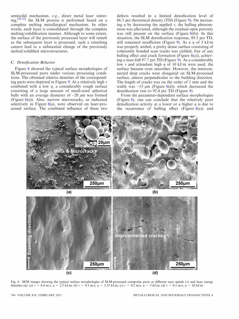
Figure 8 showed the typical surface morphologies ofSLM-processed parts under various processing condi-tions. The obtained relative densities of the correspond-ing parts were depicted in Figure 9. At a relatively high vcombined with a low g, a considerably rough surfaceconsisting of a large amount of small-sized sphericalballs with an average diameter of ~20 lm was formed(Figure 8(a)). Also, narrow microcracks, as indicatedselectively in Figure 8(a), were observed on laser-pro-cessed surface. The combined influence of these two
defects resulted in a limited densification level of86.3 pct theoretical density (TD) (Figure 9). On increas-ing g by decreasing the applied v, the balling phenom-enon was alleviated, although the residual open porositywas still present on the surface (Figure 8(b)). In thissituation, the SLM densification response, 89.5 pct TD,still remained insufficient (Figure 9). As a g of 5 kJ/mwas properly settled, a pretty dense surface consisting ofcoherently bonded scan tracks was yielded, free of anyballing effect and crack formation (Figure 8(c)), achiev-ing a near-full 97.7 pct TD (Figure 9). As a considerablylow v and attendant high g of 10 kJ/m were used, thesurface became even smoother. However, the intercon-nected deep cracks were elongated on SLM-processedsurface, almost perpendicular to the building direction.The length of cracks was on the order of 1 mm and thewidth was ~15 lm (Figure 8(d)), which decreased thedensification rate to 92.4 pct TD (Figure 9).From the parameter-dependent surface morphologies
(Figure 8), one can conclude that the relatively poordensification activity at a lower or a higher g is due tothe occurrence of balling effect (Figure 8(a)) and
Fig. 8—SEM images showing the typical surface morphologies of SLM-processed composite parts at different scan speeds (v) and laser energydensities (g): (a) v = 0.4 m/s, g = 2.5 kJ/m; (b) v = 0.3 m/s, g = 3.33 kJ/m; (c) v = 0.2 m/s, g = 5 kJ/m; (d) v = 0.1 m/s, g = 10 kJ/m.
704—VOLUME 43A, FEBRUARY 2012 METALLURGICAL AND MATERIALS TRANSACTIONS A
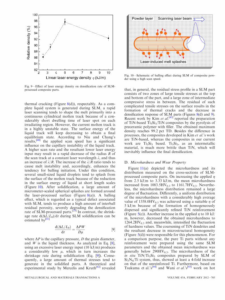
thermal cracking (Figure 8(d)), respectably. As a com-plete liquid system is generated during SLM, a rapidlaser scanning tends to shape the melt primarily into acontinuous cylindrical molten track because of a con-siderably short dwelling time of laser spot on eachirradiating region. However, the current molten track isin a highly unstable state. The surface energy of theliquid track will keep decreasing to obtain a finalequilibrium state. According to Niu and Chang’sresults,[40] the applied scan speed has a significantinfluence on the capillary instability of the liquid track.A higher scan rate and the resultant lower laser energyinput may result in a rapid decrease of the radius R ofthe scan track at a constant laser wavelength k, and thusan increase of k/R. The increase of the k/R ratio tends tocause melt instability and, accordingly, enhances thetendency for balling initiation. Under this condition,several small-sized liquid droplets tend to splash fromthe surface of the molten track because of the reductionin the surface energy of liquid at short length scales(Figure 10). After solidification, a large amount ofmicrometer-scaled spherical splashes are formed aroundthe laser-processed surface (Figure 8(a)). A ballingeffect, which is regarded as a typical defect associatedwith SLM, tends to produce a high amount of interballresidual porosity, severely degrading the densificationrate of SLM-processed parts.[25] In contrast, the shrink-age rate d(DL/L0)/dt during SLM solidification can beestimated by[41]
d DL=L0ð Þdt
¼ DPWDl
½9�
where DP is the capillary pressure, D the grain diameter,and W is the liquid thickness. As analyzed in Eq. [8],using an excessive laser energy input (10 kJ/m) producesa considerably low l, which in turn increases theshrinkage rate during solidification (Eq. [9]). Conse-quently, a large amount of thermal stresses tend togenerate in the solidified parts. A theoretical andexperimental study by Mercelis and Kruth[42] revealed
that, in general, the residual stress profile in a SLM partconsists of two zones of large tensile stresses at the topand bottom of the part, and a large zone of intermediatecompressive stress in between. The residual of suchcomplicated tensile stresses on the surface results in theformation of thermal cracks and the decrease indensification response of SLM parts (Figures 8(d) and 9).Recent work by Kim et al.[43] reported the preparationof TiN-based Ti5Si3/TiN composites by the pyrolysis ofpreceramic polymer with filler. The obtained maximumdensity reaches 99.2 pct TD. Besides the difference inprocesses, the composites developed in Kim et al.’s workare TiN-based, whereas the composites in our currentwork are Ti5Si3 based. Ti5Si3, as an intermetallicmaterial, is much more brittle than TiN, which willinevitably influence the final densification.
D. Microhardness and Wear Property
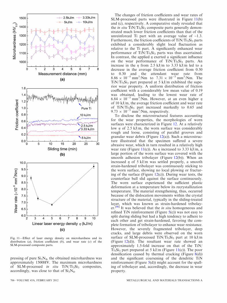
Figure 11(a) depicted the microhardness and itsdistribution measured on the cross-sections of SLM-processed composite parts. On increasing the applied gfrom 2.5 kJ/m to 3.33 kJ/m, the mean microhardnessincreased from 1083.5HV0.3 to 1161.7HV0.3. Neverthe-less, the microhardness distribution remained a largedegree of fluctuation. Differently, a uniform distributionof the microhardness with a considerably high averagevalue of 1358.0HV0.3 was achieved using a suitable g of5 kJ/m because of the formation of homogeneouslydispersed and significantly refined TiN reinforcement(Figure 5(c)). Another increase in the applied g to 10 kJ/m, however, decreased the obtained microhardness to1264.2HV0.3 and, meanwhile, intensified the fluctuationof hardness values. The coarsening of TiN dendrites andthe resultant decrease in microstructural homogeneity(Figure 5(d)) were responsible for this phenomenon. Fora comparison purpose, the pure Ti parts without anyreinforcement were prepared using the same SLMparameters and the obtained mean microhardness wasgenerally below 290HV0.3. The microhardness of thein situ TiN/Ti5Si3 composites prepared by SLM ofSi3N4/Ti system, thus, showed at least a 4-fold increaseon that of the unreinforced Ti. Furthermore, based onTsukuma et al.’s[44] and Wani et al.’s[45] work on hot
Fig. 9—Effect of laser energy density on densification rate of SLM-processed composite parts.
Fig. 10—Schematic of balling effect during SLM of composite pow-der using a high scan speed.
METALLURGICAL AND MATERIALS TRANSACTIONS A VOLUME 43A, FEBRUARY 2012—705
pressing of pure Si3N4, the obtained microhardness wasapproximately 1500HV. The maximum microhardnessof SLM-processed in situ TiN/Ti5Si3 composites,accordingly, was close to that of Si3N4.
The changes of friction coefficients and wear rates ofSLM-processed parts were illustrated in Figure 11(b)and (c), respectively. A comparative study revealed thatthe in situ TiN/Ti5Si3 composite parts generally demon-strated much lower friction coefficients than that of theunreinforced Ti part with an average value of ~1.3.Furthermore, the friction coefficients of TiN/Ti5Si3 partsexhibited a considerably slight local fluctuation asrelative to the Ti part. A significantly enhanced wearperformance of TiN/Ti5Si3 parts was thus ascertained.In contrast, the applied g exerted a significant influenceon the wear performance of TiN/Ti5Si3 parts. Anincrease in the g from 2.5 kJ/m to 3.33 kJ/m led to adecrease in the average friction coefficient from 0.50to 0.30 and the attendant wear rate from8.86 9 10�5 mm3/Nm to 7.31 9 10�5 mm3/Nm. TheTiN/Ti5Si3 part prepared at 5 kJ/m exhibited the supe-rior wear property. A uniform distribution of frictioncoefficient with a considerably low mean value of 0.19was obtained, leading to the lowest wear rate of6.84 9 10�5 mm3/Nm. However, at an even higher gof 10 kJ/m, the average friction coefficient and wear rateof TiN/Ti5Si3 part increased markedly to 0.65 and9.73 9 10�5 mm3/Nm, respectively.To disclose the microstructural features accounting
for the wear properties, the morphologies of wornsurfaces were characterized in Figure 12. At a relativelylow g of 2.5 kJ/m, the worn surface was considerablyrough and loose, consisting of parallel grooves andgranular wear debris (Figure 12(a)). Such a microstruc-ture illustrated that the specimen suffered a severeabrasive wear, which in turn resulted in a relatively highwear rate (Figure 11(c)). As g increased to 3.33 kJ/m, alarge portion of the worn surface was covered with thesmooth adhesion tribolayer (Figure 12(b)). When anincreased g of 5 kJ/m was settled properly, a smoothstrain-hardened tribolayer was continuously sticking tothe worn surface, showing no local plowing or fractur-ing of the surface (Figure 12(c)). During wear tests, thecounterface ball slid against the surface continuously.The worn surface experienced the sufficient plasticdeformation at a temperature below its recrystallizationtemperature. The material strengthening, thus, occurredbecause of the dislocation movements within the crystalstructure of the material, typically in the sliding-treatedlayer, which was known as strain-hardened tribolay-er.[46] It was believed that the in situ homogeneous andrefined TiN reinforcement (Figure 5(c)) was not easy tosplit during sliding but had a high tendency to adhere toeach other and get strain-hardened, favoring the com-plete formation of tribolayer to enhance wear resistance.However, the severely fragmented tribolayer, deepcracks, and large debris were observed on the wornsurface of SLM-processed TiN/Ti5Si3 part at 10 kJ/m(Figure 12(d)). The resultant wear rate showed anapproximately 1.5-fold increase on that of the TiN/Ti5Si3 part prepared at 5 kJ/m (Figure 11(c)). The poordensification caused by thermal cracking (Figure 8(d))and the significant coarsening of the dendritic TiNreinforcement (Figure 5(d)) might account for the spall-ing of tribolayer and, accordingly, the decrease in wearproperty.
Fig. 11—Effect of laser energy density on microhardness and itsdistribution (a), friction coefficient (b), and wear rate (c) of theSLM-processed composite parts.
706—VOLUME 43A, FEBRUARY 2012 METALLURGICAL AND MATERIALS TRANSACTIONS A

IV. CONCLUSIONS
A novel SLM process was applied to prepare bulk-form in situ TiN/Ti5Si3 composites starting from Si3N4/Ti powder system. The main conclusions were summa-rized as follows:
1. The densification response of TiN/Ti5Si3 compositeparts was controlled by the applied laser energydensity. A combination of a low laser energy den-sity (2.5 kJ/m) and a high scan speed (0.4 m/s) initi-ated the balling effect, whereas an excessive laserenergy input (10 kJ/m) resulted in the thermalcracking. Both defects that were caused by animproper laser process control lowered the densifi-cation rate. A near-full 97.7 pct theoretical densitywas achieved as an optimal laser energy density of5 kJ/m was settled properly.
2. The in situ-formed TiN reinforcing phase experi-enced a successive change in its morphologies: anirregular polyangular shape—a refined near-round
shape—a coarsened dendritic shape, on increasingthe applied laser energy density. The variationsin the liquid–solid wettability and the intensity ofMarangoni flow within the molten pool wereresponsible for the different growth mechanismsand morphologies of the TiN phase.
3. The optimally prepared TiN/Ti5Si3 composite partshad a uniform microhardness distribution with anincreased mean value of 1358.0HV0.3, showing atleast a 4-fold increase on that of the unreinforcedTi. A considerably low friction coefficient of 0.19without any apparent fluctuation and a decreasedwear rate of 6.84 9 10�5 mm3/Nm were obtained insliding wear tests. The formation of adherent strain-hardened tribolayer covered on the worn surfaceaccounted for the improvement of wear performance.However, the microhardness and wear resistancedecreased at an excessive laser energy input becauseof the formation of thermal cracks and the signifi-cant coarsening of TiN dendritic reinforcement.
Fig. 12—SEM images showing characteristic morphologies of worn surfaces of SLM-processed composite parts at various laser energy densities(g): (a) g = 2.5 kJ/m; (b) g = 3.33 kJ/m; (c) g = 5 kJ/m; (d) g = 10 kJ/m.
METALLURGICAL AND MATERIALS TRANSACTIONS A VOLUME 43A, FEBRUARY 2012—707
ACKNOWLEDGMENTS
One author (D.D.G.) gratefully appreciates the fel-lowship of the Alexander von Humboldt Foundationfor sponsoring the research stay in Germany. Finan-cial supports from the National Natural Science Foun-dation of China (No. 51054001 and No. 51104090),the Aeronautical Science Foundation of China (No.2010ZE52053), the Natural Science Foundation ofJiangsu Province (No. BK2009374), and the NUAAResearch Funding (No. NS2010156) are appreciated.
REFERENCES1. R. Mitra: Metall. Mater. Trans. A, 1998, vol. 29A, pp. 1629–41.2. R. Mitra and V.V. Rama Rao: Metall. Mater. Trans. A, 1998,
vol. 29A, pp. 1665–75.3. J.H. Shim, J.S. Byun, and Y.W. Cho: J. Am. Ceram. Soc., 2004,
vol. 87, pp. 1853–58.4. L.J. Wang, W. Jiang, C. Qin, and L.D. Chen: J. Mater. Sci., 2006,
vol. 41, pp. 3831–35.5. I.J. Shon, H.C. Kim, D.H. Rho, and Z.A. Munir:Mater. Sci. Eng.
A, 1999, vol. 269, pp. 129–35.6. J.L. Li, D.L. Jiang, and S.H. Tan: J. Eur. Ceram. Soc., 2002,
vol. 22, pp. 551–58.7. S.C. Tjong: Adv. Eng. Mater., 2007, vol. 9, pp. 639–52.8. A. Gaard, P. Krakhmalev, and J. Bergstrom: J. Alloys Compd.,
2006, vol. 421, pp. 166–71.9. D.D. Gu, Y.C. Hagedorn, W. Meiners, K. Wissenbach
R. Poprawe: Surf. Coat Technol., 2011, vol. 205, pp. 3285–92.10. J.F. Shackelford and W. Alexander: CRC Materials Science and
Engineering Handbook, 3rd ed., CRC Press, Boca Raton, FL,2000.
11. M.A. Thein, L. Lu, and M.O. Lai: Mater. Sci. Eng. A, 2010,vol. 528, pp. 239–46.
12. V. Abbasi Chianeh, H.R. Madaah Hosseini, and M. Nofar:J. Alloys Compd., 2009, vol. 473, pp. 127–32.
13. C.L. Yeh and G.S. Teng: J. Alloys Compd., 2007, vol. 429,pp. 126–32.
14. D. Horvitz and I. Gotman: Acta Mater., 2002, vol. 50, pp. 1961–71.
15. Y.F. Yang, H.Y. Wang, J. Zhang, R.Y. Zhao, Y.H. Liang, andQ.C. Jiang: J. Am. Ceram. Soc., 2008, vol. 91, pp. 2736–39.
16. S. Kumar, V. Subramaniya Sarma, and B.S. Murty: Metall.Mater. Trans. A, 2010, vol. 41A, pp. 242–54.
17. R. Hadian, M. Emamy, and J. Campbell: Metall. Mater. Trans. B,2009, vol. 40B, pp. 822–32.
18. B. Zheng, T. Topping, J.E. Smugeresky, Y. Zhou, A. Biswas, D.Baker, and E.J. Lavernia:Metall. Mater. Trans. A, 2010, vol. 41A,pp. 568–73.
19. B. Zheng, J.E. Smugeresky, Y. Zhou, D. Baker, and E.J. Lavernia:Metall. Mater. Trans. A, 2008, vol. 39A, pp. 1196–205.
20. B.V. Krishna, S. Bose, and A. Bandyopadhyay: Metall. Mater.Trans. A, 2007, vol. 38A, pp. 1096–1103.
21. W.P. Liu and J.N. DuPont: Metall. Mater. Trans. A, 2005,vol. 36A, pp. 3397–406.
22. R. Banerjee, A. Genc, P.C. Collins, and H.L. Fraser: Metall.Mater. Trans. A, 2004, vol. 35A, pp. 2143–52.
23. J.P. Kruth, G. Levy, F. Klocke, and T.H.C. Childs: CIRP Ann.Manuf. Technol., 2007, vol. 56, pp. 730–59.
24. D. Bourell, M. Wohlert, N. Harlan, S. Das, and J. Beaman: Adv.Eng. Mater., 2002, vol. 4, pp. 663–69.
25. S. Das: Adv. Eng. Mater., 2003, vol. 5, pp. 701–11.26. A. Simchi, F. Petzoldt, and H. Pohl: Int. J. Powder Metall., 2001,
vol. 37, pp. 49–61.27. S. Kumar and J.P. Kruth: Mater. Des., 2010, vol. 31, pp. 850–56.28. D.D. Gu and W. Meiners: Mater. Sci. Eng. A, 2010, vol. 527,
pp. 7585–92.29. D.D. Gu and Y.F. Shen: Acta Metall. Sin., 2010, vol. 46, pp. 761–
68.30. D.D. Gu and Y.F. Shen: J. Alloys Compd., 2009, vol. 473, pp. 107–
15.31. P. Fischer, V. Romano, H.P. Weber, N.P. Karapatis, E. Boillat,
and R. Glardon: Acta Mater., 2003, vol. 51, pp. 1651–62.32. A. Simchi and H. Pohl: Mater. Sci. Eng. A, 2003, vol. 359,
pp. 119–28.33. Q.L. Huang, J. Cai, W. Pan, J. Chen, and J. Lian: Mater. Lett.,
1997, vol. 31, pp. 221–25.34. I. Barin: Thermochemical Data of Pure Substances, 3rd ed., VCH,
New York, NY, 1993.35. D.D. Gu, Y.F. Shen, and Z.J. Lu: Mater. Lett., 2009, vol. 63,
pp. 1577–79.36. K. Arafune and A. Hirata: J. Cryst. Growth, 1999, vol. 197,
pp. 811–17.37. X.B. Zhou and J.Th.M. De Hosson: Acta Mater., 1996, vol. 44,
pp. 421–26.38. Z.F. Yuan, J.J. Ke, and J. Li: Surface Tension of Metals and
Alloys, 1st ed., Science Press, Beijing, China, 2006.39. I. Takamichi and I.L.G. Roderick: The Physical Properties of
Liquid Metals, 1st ed., Clarendon Press, Oxford, UK, 1993.40. H.J. Niu and I.T.H. Chang: Scripta Mater., 1999, vol. 41,
pp. 1229–34.41. H.H. Zhu, L. Lu, and J.Y.H. Fuh: Mater. Sci. Eng. A, 2004,
vol. 371, pp. 170–77.42. P. Mercelis and J.P. Kruth: Rapid Prototyping J., 2006, vol. 12,
pp. 254–65.43. B.S. Kim, S.J. Hong, and D.J. Kim: Metall. Mater. Int., 2010,
vol. 16, pp. 565–68.44. K. Tsukuma, M. Shimada, and M. Koizumi: Ceram. Bull., 1981,
vol. 60, pp. 910–12.45. M.F. Wani, Z.A. Khan, and M. Hadfield: J. Adv. Res. Mech. Eng.,
2010, vol. 1, pp. 52–59.46. A. Jain, B. Basu, B.V. Manoj, K. Harshavardhan, and J. Sarkar:
Acta Mater., 2010, vol. 58, pp. 2313–23.
708—VOLUME 43A, FEBRUARY 2012 METALLURGICAL AND MATERIALS TRANSACTIONS A