Embed Size (px)
Citation preview

DENISON HYDRAULICS
VANE TROUBLESHOOTING GUIDE
1 - EN0721 - A 02 / 99 / 5000 / replaces SI - EN175 - A
DENISON Hydraulics

VANE TROUBLESHOOTING GUIDE

V - COMPONENT ANALYSIS CHARTPages bushing cam ring pins rotor screws seals shaft side plates vanes Pages
12
13
14
15
16
17
18
19
20
21
22
23
24
25
26
27
28
29
30
31
32
33
34
35
36
37
38
39
40
41
42
43
44
45
46
47
48
49
X
X
X
X
X
X
X X
45
46
47
48
49
12
13
14
15
16
17
18
19
20
21
22
23
24
25
26
27
28
29
30
31
32
33
34
35
36
37
38
39
40
41
42
43
44
X X
X
X
X
X
X
X
X
X
X
X
X
X
X
X
X
X
X
X
X
X
X
X
X X X
X
X
X
X
X
X
X
X
X
X
X
X
X
X
X
X
X
X
X
X
X
X
X
X
X
VANE TROUBLESHOOTING GUIDE
PU
MP
MO
TO
R X
X
XX

VANE PUMP COMPONENTS DESIGNATION
Part nb. part designation Part nb. part designation123456789101112131415
End capSquare section seal P1 & P2Back-up ring P1 & P2Pressure port plate P2Rotor-insert assembly P2Rear port plate P2BushCam ring P1 & P2O ringRotor-insert assembly P1Square section seal P1 & P2KeyKeyed shaftSplined shaftBall bearing
1617181920212223242526272829
Round section ringMounting capPin-vane holdout (P1 & P2)HousingVane P1 & P2Square section sealScrewDowel pinRear port plate P1Dowel pinPressure port plateScrewShaft sealScrew
VANE TROUBLESHOOTING GUIDE

CONTENTS
I INTRODUCTION
I -1 PRESENTATION
I -2 HOW TO USE THIS GUIDE
I -3 WHY A DENISON VANE PUMP SHOULD NOT BREAK DOWN
I -4 BASIC PRECAUTIONS FOR A LONG LIFE TIME
2
2
2
2
5
6
7
12
18
24
44
50
51
58
Folded first pageV COMPONENT ANALYSIS CHART
IV TROUBLESHOOTING TABLE
IV -1 PUMPS
IV -2 MOTORS
III SPECIFICS OF VANE MOTOR FAILURES AND CAUSES
II ANALYSIS OF FAILURES
II -1 MECHANICAL FAILURES
II -2 THE CONSEQUENCES OF MECHANICAL FAILURES
II -3 PRESSURE FAILURES
II -4 PHYSICAL, CHEMICAL OR HYDRAULIC FAILURES
1
VANE TROUBLESHOOTING GUIDE

VANE TROUBLESHOOTING GUIDE
I INTRODUCTION
I-1 Presentation
The main goal of this guide is to help all the
DENIS ON vane pump users to understand the
principal causes of destruction of these pumps
and motors in service. Our past experience has
shown that the failures, occurring in the first 500
hours of service, are premature failures. Failing to
follow instructions or ignoring the correct appli-
cation limits and functioning of the units inevita-
bly leads to premature failures. It is important to
point out that 80 % of the failures are linked to
fluid contamination incidents (chapter II-4).
This guide comes as an addition to the existing
"Installation, operation and overhaul instruc-
tions" available bulletin S1-EN081.
I-2 How to use this guide
• "The most common causes", chapter II (pages 6 to 43): details of the major incidents you may encoun-
ter (cavitation, aeration, misalignment...) and their consequences on the vane pumps. While chapter III
(pages 44 to 49) will concern the vane motors.
• "Fault finding while the pump is running", chapter IV (pages 50 to 60): the troubleshooting tables
for vane pumps and motors. If you have a problem in working conditions, "the troubleshooting table" will
help you to find out what is wrong (FAILURE-CAUSE-SOLUTION).
• "Interpret the physical damages on components", chapter V: The first page (folded) shows a chart
which summarizes all the pictures of failed components. This will enable you to recognize the failed com-
ponent and to understand the cause of this failure.
I-3 Why a DENISON Vane pump should not break down
Unlike most other hydraulic technologies, the
DENISON vane pump design is hydraulically
balanced. You cannot calculate the life time of
these pumps by calculating the life time of the ball
bearing as no internal load (neither axial nor
radial) is applied on the shaft. The only purpose of
the ball bearing in the Denison vane pump is to
absorb any external shaft misalignment or abnor-
mal coupling loads.
As shown on the drawings hereafter, the two sym-
metrical high pressure zones have a self centering
effect on the rotating components.
This is a hydrostatic balanced pump, axially and
radially.
2

VANE TROUBLESHOOTING GUIDE
DENISON HYDRAULICSVane Pumps
Single series T6 - T7 - B-C-D-E sizes
Publ. 034-67110-2 02/98/5000/FB
DENISON Hydraulics
3

VANE TROUBLESHOOTING GUIDE
Each single vane is independently loaded in order
to always be maintained on the cam ring contour.
The specific Denison pin design reduces the pos-
sible internal leakage, reduces the possible
vane/cam ring wear (due to a precise balancing of
the forces under and over the vanes), lowers consi-
derably the noise level, allowing higher pressure
capabilities, extends the life time...
Added to this licensed pin design, Denison has
engineered the double vane lip technology. This
vane technology combined with the pin design
gives unique overall performances. The double lips
allow the pressure all around the vane to be the
same on the top as on the bottom and as on the
sides of it. This is possible because of the double
lips and the balancing through the holes in the
vanes. Here again, the components are hydrostati-
cally balanced. Another advantage of the double
lip design is the fact that the first lip seals the low
pressure area and the other one seals the high pres-
sure area. This increases the life time of the pump
when working with contaminated oil. The wear,
due to the particles of pollution, will have a nega-
tive effect, mainly on the first lip. The second lip,
working in the high pressure area, keeps its origi-
nal seal to maintain high volumetric efficiency.
This technology is unique because the wear is
compensated. The effect of contamination on the
Denison vane design is not a major issue of pump
failure as for other pump technologies.
Every port plate and cam ring has a surface treat-
ment to increase the life time capabilities.
On each cam ring, for example, a dry lubricant
coating is laid on the cam profile. This coating
will assure, even in bad priming conditions, a
good start-up minimizing the risk of micro-sei-
zures. With this dry lubricant coating, the defi-
ciency of oil is compensated but not replaced.
This is done for short term deficiencies.
Our passed experience shows that the most com-
mon failures are linked to the quality of the oil. As
soon as there is a lack of lubricity, the failure is
imminent. In addition to the pressure and the
mechanical failures, all the problems are usually a
lack of lubrication (rupture of the film of oil). The
followings are some examples of the common
causes:- air in the oil (cavitation, aeration),
- solid large size particles,
- chemical agents (water, wrong additives, tar...),
- too high or too low viscosity,
- overheating (shaft alignment),
- flow of the system coming back to the pump,
- poor quality of oil loosing its main chemical
characteristics,
This is why good filtration, good thermal stability,
good quality of oil, a good design (hose design,
bleeder, tank design ...), correct hydraulic know-
ledge (...) will always increase the life time of all
hydraulic components.
The DENISON vane pump technology is a heavy
duty engineering design that will last years if ele-
mentary precautions are taken.
4

VANE TROUBLESHOOTING GUIDE
I-4 Basic precautions for a long life time:
The Denison vane products are designed for long
life. Some minor precautions can help to avoid
premature breakdowns:
- have a correct air bleed at start-up,
- always check the oil velocity (inlet & outlet).
This should then give the correct sizes of hoses
& connectors: maximum velocity of 1,9 m/sec.
for the inlet & 6 m/sec. for the outlet,
- no strainer on the inlet line is preferred (250
microns minimum and check the pressure drop
when the Viscosity rises),
- always pay attention to the viscosity of the oil
versus temperature. Even a small change in tem-
perature can have a big effect on the viscosity. A
good quality return line filter is the best solution.
- check the pressure at the inlet port, (position of
the tank, shaft rotational speed...),
- ratio flow/tank capacity: is cooling required ?
- good shaft alignment is a classic "weakness", as
well as proper coupling with the driving source.
The lubrication of these links is also something
to look after,
- proper oil selection versus application condition:
viscosity index, viscosity grade (ISO 32,46,
68...), environment (biodegradability, fire resis-
tance, normal conditions), pumping temperature
range, filterability, deaeration, thermal stability
are the basics to consider for a good fluid,
- if the pump is used on a very fast pressure
cycling machine, attention should be paid to the
relationship between the pressure rise/fall gra-
dient and the inlet pressure in order to avoid
cavitation. We recommend maximum limits of
5000 bar per second (72500 PSI/ second) for
pressure rise and 6000 bar per second (87000
PSI) for presssure fall.
5

II ANALYSIS OF FAILURES
II -1 MECHANICAL FAILURES
II -2 CONSEQUENCES OF MECHANICAL FAILURES
II -3 PRESSURE FAILURES
II -3-1 Pressure overshoot
II -3-2 Instant pressure overshoot
II -3-3 Consequences of instant pressure overshoot
II -3-4 Cycled overpressurization
II -3-5 Consequences of cycled overpressurization
II -3-6 Pressure gradients
II -3-7 Consequences of too high pressure gradients
II -4 PHYSICAL, CHEMICAL OR HYDRAULIC FAILURES
II-4-1 Start-up without a proper air bleed
II-4-2 Air pollution (Foaming-Aeration, Cavitation-Deaeration)
II-4-2-1 Aeration
II-4-2-2 Consequences of Aeration
II-4-2-3 Cavitation
II-4-2-4 Consequences of Cavitation
II-4-3 Solid particle contamination
II-4-4 Consequences of solid particle contamination
II-4-5 Water contamination
II-4-6 Consequences of Water contamination
II-4-7 Viscosity failures
II-4-8 Consequences of Viscosity failures
II-4-9 Unsuitable fluids
II-4-10 Unsuitable grease
7
12
18
18
18
18
20
21
23
23
24
25
25
25
26
28
29
33
33
37
38
39
40
41
43
VANE TROUBLESHOOTING GUIDE
6

VANE TROUBLESHOOTING GUIDE
II ANALYSIS OF FAILURES
The systematic analysis of failures permits the
causes to be determined logically, these failures
being either distortion, shearing, surface seizure
or scoring.
If the failure is shearing, we can almost certainly
say it is the consequence of a brutal or a fatigue
failure. A brutal failure is due to sudden increase
in loads exceeding the material strength limit or
its resistance to shocks. A fatigue failure is the
result of the tensile limit of the sensitive point of a
component.
Studying the crystalline faces will allow us to
determine the mechanical causes that provoked
the failure. This troubleshooting guide has been
prepared to allow everyone to quickly reach a
satisfactory conclusion. A precise and professional
analysis to determine the problem is not really the
purpose of this guide.
II-1: MECHANICAL FAILURES
Mechanical failures are due to physical external
parameters that change the mechanical structure
of the materials. The causes of these incidents are
mostly axial and radial shaft overloads. Rotary
bending (flexion) and torsion (twisted) fatigue fai-
lures.
II-1-1 - Problems onshafts: bad alignment,
bad mechanical link
(bracket, chassis defor-
mation, bad bell hou-
sing, too loose damping
elements...) can create:
a) misalignment
b) out of squareness
consequence page- Fretting P 12, II-2-1
- Shaft rupture P 12, II-2-2-1
P 13, II-2-2-2
- Rear bushing P 15, II-2-5-1
P 15, II-2-5-2
P 15, II-2-5-3
- Cam ring marked P 15, II-2-6
- Shaft seal problem P 16, II-2-7
- Dissymmetrical wear on port
plate P 16, II-2-8
- Ball bearing worn or destroyed
- Fretting P 12, II-2-1
- Shaft rupture P 12,
P 13, II-2-2-2
- Rear bushing P 15, II-2-5-1
P 15, II-2-5-2
P 15, II-2-5-3
- Cam ring marked P 15, II-2-6
- Shaft seal problem P 16, II-2-7
- Dissymmetrical wear on port
plate P 16, II-2-8
- Ball bearing worn or destroyed
II
7
II-2-2-1

II-1: MECHANICAL FAILURES (continuation)
II-1-1-1 - Too tight gap
between the two cou-
pling flanges (axial
loads/radial loads).
consequence page
- Fretting corrosion P 12, II-2-1
- Shaft rupture P 12,
P 13, II-2-2-2
- Ball bearing worn out
- Rear bushing P 15, II-2-5-1
P 15, II-2-5-2
P 15, II-2-5-3
- Check with the coupling manu-
facturer to convenient clearance
required depending on the
torque.
- Shaft rupture P 13,
- Bushing P 15, II-2-5
- Cam ring marked P 15, II-2-6
- Shaft seal problem P 16, II-2-7
- Dissymmetrical wear on port
plate P 16, II-2-8
- Shaft rupture P
- Bushing P 15, II-2-5
- Cam ring marked P 15, II-2-6
- Shaft seal problem P 16, II-2-7
- Too greatmoment of inertia due
to heavy couplings (like
chain couplings) or
very large diameter
couplings.
II-1-1-4
II-1-1-3
- Unbalanced
coupling = radial load.
- Too high load
on a belt driven system
(belt drives not recom-
mended).
- Non-homoki-
netic transmission due
to unbalanced cardan
shaft (or universal joint)
means inconstant shaft
speed.
VANE TROUBLESHOOTING GUIDE
8
II-2-2-1
II-2-2-2
13, II-2-2-2
II-1-1-2
II-1-1-5
- Shaft rapture P 12, II-2-2-1
P 13, II-2-2-2
- Rear bushing P 15, II-2-5-1
P 15, II-2-5-2
P 15, II-2-5-3
- Shaft rapture P 13, II-2-2-3
(torsional fatigue)
- Shaft wear P 14, II-2-3
P 14, II-2-4
- Shaft rapture P 12, II-2-2-1
P 13, II-2-2-2
- Bushing problems P 15, II-2-5
- Marked cam ring P 15, II-2-6
- Seal problems P 16, II-2-7
- Wear on port plate P 16, II-2-8
- Shaft rapture P 12,
P 13, II-2-2-2
- Bushing problems P 15, II-2-5
- Marked cam ring P 15, II-2-6
- Seal problems P 16, II-2-7
- Wear on port plate P 16, II-2-8
consequence page
II-1: MECHANICAL FAILURES (continuation)
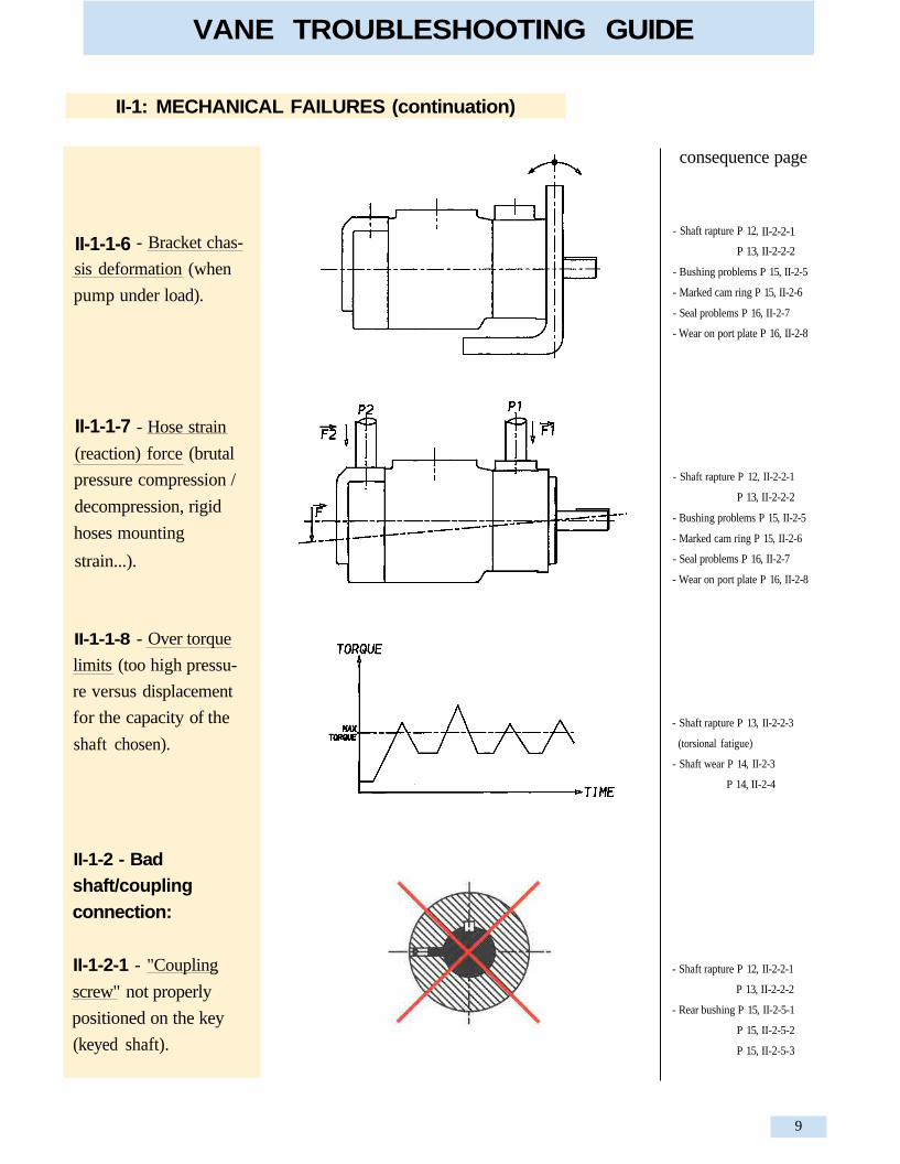
II-1-1-7
- Bracket chas-
sis deformation (when
pump under load).
- Hose strain
(reaction) force (brutal
pressure compression /
decompression, rigid
hoses mounting
strain...).
II-1-1-8 - Over torque
limits (too high pressu-
re versus displacement
for the capacity of the
shaft chosen).
II-1-2 - Badshaft/couplingconnection:
II-1-2-1 - "Coupling
screw" not properly
positioned on the key
(keyed shaft).
VANE TROUBLESHOOTING GUIDE
9
II-1-1-6 II-2-2-1

II-1: MECHANICAL FAILURES (continuation)
consequence page
- Fretting P 12, II-2-1
- Shaft rupture P 13, II-2-2-3
- Shaft worn out P 14, II-2-4
- Shaft rupture P 14, II-2-3
P 14, II-2-4
- Wear of the splines P 14, II-2-3
- Wear of the key P 14, II-2-4
- Spline wear P 14, II-2-3
- Dowel pin rupture P 16, II-2-9
- No pressure possible
- Unconstant flow
- Cavitation
- Noisy
II-1-3 - Cartridgedowel pin not posi-tioned correctly inthe housing.
II-1-2-2 - Bad manu-
facturing (machining)
of the couplings:
- bad diameter fit tole-
rance between the shaft
diameter and the cou-
pling diameter
- key way in the cou-
pling is not properly
centered with the main
bore axis
- bad heat treatment
(too high or too low)
II-1-2-4 - Bad (or no)
lubrication of splined
shafts/coupling.Denison Hydraulics requires for the lubrication of the
shafts a grease with "disulfide of molybdenum" base.
- Shaft not pro-
perly utilized (too small
surface of spline or key
used)
VANE TROUBLESHOOTING GUIDE
10
II-1-2-3

consequence page
II-1: MECHANICAL FAILURES (continuation)
II-1-4
- Vane marks P 11, II-1-7
- Vane marks P 17, II-2-12
- Noisy
- Flow unstable
-Broken screws P 17, II-2-11
- Vane marks P 17, II-2-12
- Noisy
- Pressure limited
- Flow unconstant
- Marks on distribution
plates that disturb the cycle of
the pump. Even a small scratch
between the inlet & the pressure
area can destabilize the vane.
- Loose pump fasteners
(after modifying the pump, the
screws were not tightened at the
proper torque and worked
loose).
- Hollow pin-vane hold-
out wrongly mounted in the
T6*M, Mobile version (pin up
side down).
- Cartridge screws not
properly mounted (after a car-
tridge modification, no precau-
tion has been taken to see if the
rotor/vanes could rotate freely
in the newly built cartridge.
Some vanes can have tilted and
therefore be squeezed inbetween
the port plates). These screws
should be lightly tightened as
they just hold pieces together to
obtain a cartridge. After reas-
sembling a cartridge, always
check if the rotor & vanes can
rotate freely in the cartridge.
VANE TROUBLESHOOTING GUIDE
11
II-1-7
II-1-6
II-1-5

II-2: THE CONSEQUENCES OF MECHANICAL FAILURES:
II-2-1 - Fretting cor-rosion.
incident page
- Bad shaft / coupling link
P 9, II-1-2-1
- Bad coupling manufacturing
P 10, II-1-2-2- Bad grease when assembly
- Bad alignment P 7, II-1-1a
- Out of squareness P 7, II-1-1b
- Unbalanced coupling
P 8, II-1-1-2
- Too high radial load
P 8, II-1-1-3
- Non homokinetic P 8, II-1-1-4
- Too great moment of inertia
P 8, II-1-1-5
- Bracket chassis deformation
P 9, II-1-1-6
- Hose strain force P 9, II-1-1-7
- Bad shaft / coupling link
P 9, II-1-2-1
II-2-2 - Fatigue shaftrupture:
- Perpendicular, center,
rotational bending
fatigue rupture.
This phenomenon
appears when the soli-
citations are great and
when there is a slight
vibration movement.
These movements will
"create" metallic
oxides. Being very
abrasive, they will wea-
ken the structure of the
component and will
favour start-up of the
fatigue rupture (twis-
ted).
VANE TROUBLESHOOTING GUIDE
12
II-2-2-1

II-2: THE CONSEQUENCES OF MECHANICAL FAILURES: (continuation)
Perpendicular,
over-center rotational
bending fatigue rupture.
incident page
- Bad alignment P 7, II-1-1a
- Out of squareness P 7, II-1-1b
- Unbalanced coupling
P 8, II-1-1-2
- Too high radial load
P 8, II-1-1-3
- Non homokinetic P 8, II-1-1-4
- Too great moment of inertia
P 8, II-1-1-5
- Bracket chassis deformation
P 9, II-1-1-6
- Hose strain force P 9, II-1-1-7
- Bad shaft / coupling link
P 9, II-1-2-1
- Fretting corrosion
P 12, II-2-1
- Over torque limits
P 9, II-1-1-8
II-2-2-3 -
sional rupture.
Twisted tor-
VANE TROUBLESHOOTING GUIDE
13
II-2-2-2 -

II-2: THE CONSEQUENCES OF MECHANICAL FAILURES:
II-2-2-4
- Perpendicular, torsio-
nal fatigue rupture.
incident page
- Torsional fatigue with peak
torque values
P 9, II-1-1-8
- Bad shaft / coupling connection
P 10, II-1-2-2
- Bad lubricant (Grease)
- Over torque values
P 9, II-1-1-8
- Highly cycled
II-2-3 - Shaft splines/keyed shaft wornout on total length.
- Over torque values
P 9, II-1-1-8
- Utilized key surface or splined
surface too small
P 10, II-1-2-3
II-2-4 - Shaft splines/keyed shaft wornout on part of thelength.
VANE TROUBLESHOOTING GUIDE
14

II-2: THE CONSEQUENCES OF MECHANICAL FAILURES: (continuation)
II-2-5 - Bushing/bea-ring problems
II-2-5-1 - Front or back
bearing/bushing with
heavy wear
incident page
- Problems on shafts
P 7, 8, 9, II-1-1
- Bad shaft / coupling connection
P 9, 10, II-1-2
- Problems on shafts
P 7, 8, 9, II-1-1
- Bad shaft / coupling connection
P 9, 10, II-1-2
- Problems on shafts
P 7, 8, 9, II-1-1
- Bad shaft / coupling connection
P 9, 10, II-1-2
- Problems on shafts
P 7, 8, 9, II-1-1
- Bad shaft / coupling connection
P 9, 10, II-1-2
II-2-5-3 - Back bushing
moving out of the rear
port plate
II-2-6 - Cam ringmarked by the rotor
on the smallest diame-
ter. If the contact bet-
ween the rotor and the
cam ring is important, it
will transform the hard-
ness of the cam ring
and create local ten-
sions (cracks).
II-2-5-2 - Bushing
"welded" on the shaft
VANE TROUBLESHOOTING GUIDE
15
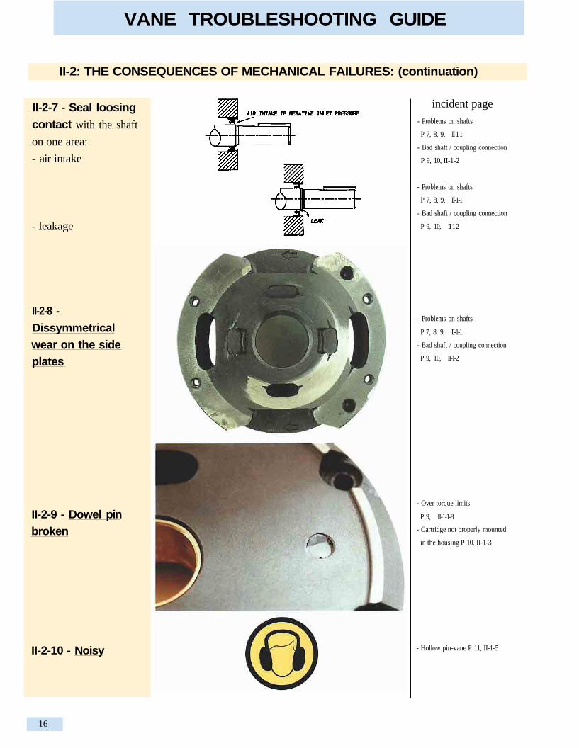
II-2-10 - Noisy - Hollow pin-vane P 11, II-1-5
- Over torque limits
P 9, II-1-1-8
- Cartridge not properly mounted
in the housing P 10, II-1-3
II-2-9 - Dowel pinbroken
Dissymmetricalwear on the sideplates
- Problems on shafts
P 7, 8, 9, II-1-1
- Bad shaft / coupling connection
P 9, 10, II-1-2
- Problems on shafts
P 7, 8, 9, II-1-1
- Bad shaft / coupling connection
P 9, 10, II-1-2
- Problems on shafts
P 7, 8, 9, II-1-1
- Bad shaft / coupling connection
P 9, 10, II-1-2
incident pageII-2-7 - Seal loosingcontact with the shaft
on one area:
- air intake
- leakage
II-2: THE CONSEQUENCES OF MECHANICAL FAILURES: (continuation)
VANE TROUBLESHOOTING GUIDE
16
II-2-8 -

II-2: THE CONSEQUENCES OF MECHANICAL FAILURES: (continuation)
II-2-11 - Brokenscrews
incident page
- Loose pump fasteners
P 11, II-1-6
- Cartridge not properly assem-
bled P 11, II-1-4
- Cartridge not properly assem-
bled P 11, II-1-4
- Tilted vanes but the
pump did rotate. The
result is scars on the
port plate.
- Tilted vanes marked
the port plate but the
pump did not rotate.
II-2-12 - Parallelmarks on the portplate (vane marks)
VANE TROUBLESHOOTING GUIDE
17
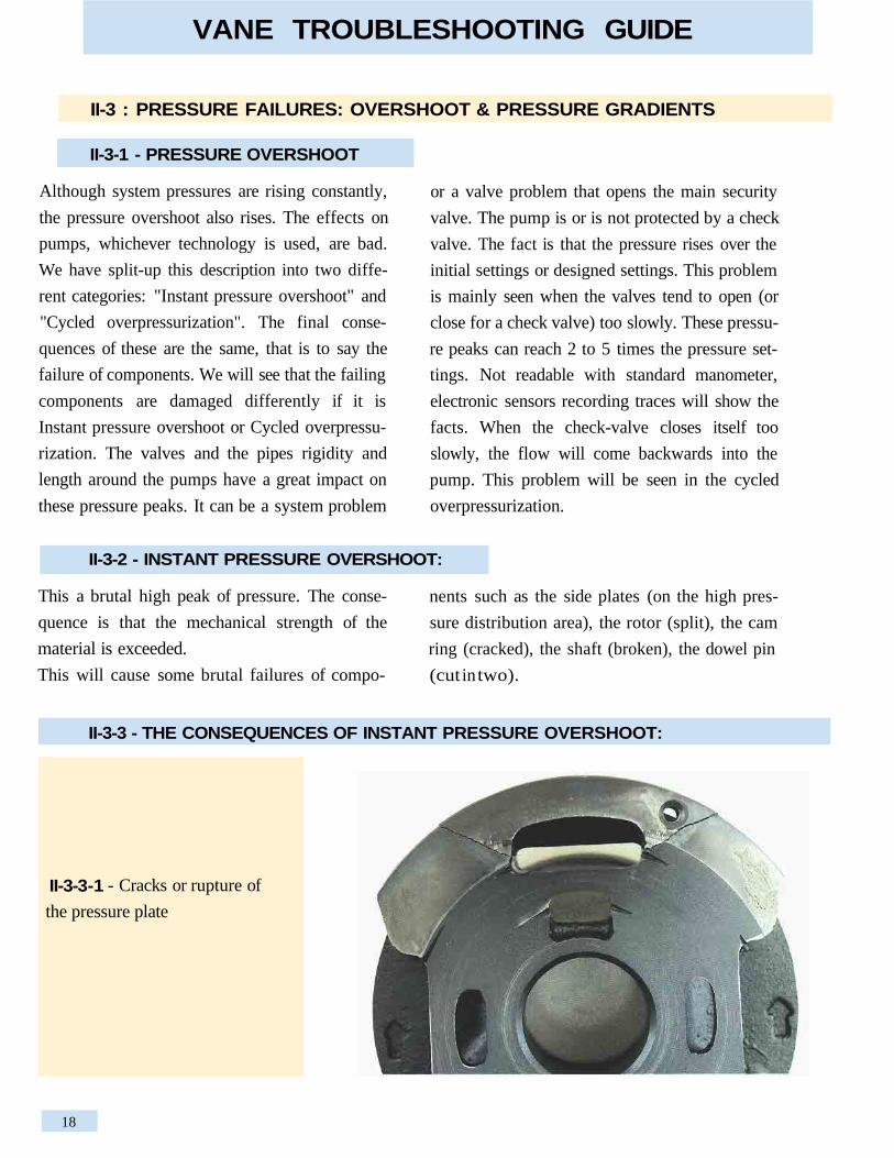
- Cracks or rupture of
the pressure plate
II-3-3 - THE CONSEQUENCES OF INSTANT PRESSURE OVERSHOOT:
This a brutal high peak of pressure. The conse-
quence is that the mechanical strength of the
material is exceeded.
This will cause some brutal failures of compo-
nents such as the side plates (on the high pres-
sure distribution area), the rotor (split), the cam
ring (cracked), the shaft (broken), the dowel pin
(cut in two).
II-3-2 - INSTANT PRESSURE OVERSHOOT:
II-3 : PRESSURE FAILURES: OVERSHOOT & PRESSURE GRADIENTS
II-3-1 - PRESSURE OVERSHOOT
Although system pressures are rising constantly,
the pressure overshoot also rises. The effects on
pumps, whichever technology is used, are bad.
We have split-up this description into two diffe-
rent categories: "Instant pressure overshoot" and
"Cycled overpressurization". The final conse-
quences of these are the same, that is to say the
failure of components. We will see that the failing
components are damaged differently if it is
Instant pressure overshoot or Cycled overpressu-
rization. The valves and the pipes rigidity and
length around the pumps have a great impact on
these pressure peaks. It can be a system problem
or a valve problem that opens the main security
valve. The pump is or is not protected by a check
valve. The fact is that the pressure rises over the
initial settings or designed settings. This problem
is mainly seen when the valves tend to open (or
close for a check valve) too slowly. These pressu-
re peaks can reach 2 to 5 times the pressure set-
tings. Not readable with standard manometer,
electronic sensors recording traces will show the
facts. When the check-valve closes itself too
slowly, the flow will come backwards into the
pump. This problem will be seen in the cycled
overpressurization.
VANE TROUBLESHOOTING GUIDE
18
II-3-3-1

II-3-3-4 - Shaft broken: perpen-
dicular "clean cut"
II-3-3-3 - Cam ring cracked
II-3-3-2 - Cracks or rupture of
the rotor
II-3-3 - THE CONSEQUENCES OF INSTANT PRESSURE OVERSHOOT: (continuation)
VANE TROUBLESHOOTING GUIDE
19
II-3-3 - THE CONSEQUENCES OF INSTANT PRESSURE OVERSHOOT: (continuation)
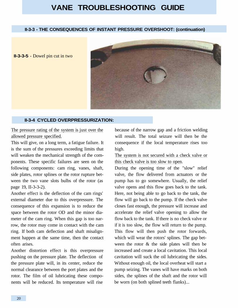
II-3-3-5 - Dowel pin cut in two
II-3-4 CYCLED OVERPRESSURIZATION:
The pressure rating of the system is just over theallowed pressure specified.This will give, on a long term, a fatigue failure. Itis the sum of the pressures exceeding limits thatwill weaken the mechanical strength of the com-ponents. These specific failures are seen on thefollowing components: cam ring, vanes, shaft,side plates, rotor splines or the rotor rupture bet-ween the two vane slots bulbs of the rotor (aspage 19, II-3-3-2).Another effect is the deflection of the cam rings'external diameter due to this overpressure. Theconsequence of this expansion is to reduce thespace between the rotor OD and the minor dia-meter of the cam ring. When this gap is too nar-row, the rotor may come in contact with the camring. If both cam deflection and shaft misalign-ment happen at the same time, then the contactoften arises.Another distortion effect is this overpressurepushing on the pressure plate. The deflection ofthe pressure plate will, in its center, reduce thenormal clearance between the port plates and therotor. The film of oil lubricating these compo-nents will be reduced. Its temperature will rise
because of the narrow gap and a friction weldingwill result. The total seizure will then be theconsequence if the local temperature rises toohigh.The system is not secured with a check valve orthis check valve is too slow to open.During the opening time of the "slow" reliefvalve, the flow delivered from actuators or thepump has to go somewhere. Usually, the reliefvalve opens and this flow goes back to the tank.Here, not being able to go back to the tank, theflow will go back to the pump. If the check valvecloses fast enough, the pressure will increase andaccelerate the relief valve opening to allow theflow back to the tank. If there is no check valve orif it is too slow, the flow will return to the pump.This flow will then push the rotor forwards,which will wear the rotors' splines. The gap bet-ween the rotor & the side plates will then beincreased and create a local cavitation. This localcavitation will suck the oil lubricating the sides.Without enough oil, the local overheat will start apump seizing. The vanes will have marks on bothsides, the splines of the shaft and the rotor willbe worn (on both splined teeth flanks)...
VANE TROUBLESHOOTING GUIDE
20

- rotor/cam ring contact in the"small diameter"
- Vanes
II-3-5-2 - Cam ring:
-rupture/cracks
II-3-5 THE CONSEQUENCES OF CYCLED OVERPRESSURIZATION:
VANE TROUBLESHOOTING GUIDE
21
II-3-5-1

II-3-5 THE CONSEQUENCES OF CYCLED OVERPRESSURE: (continuation)
II-3-5-3 - Shaft:
- internal splines worn
- rupture:
torsional fatigue ruptures
Perpendicular: few cycles but
very high torque
Twisted: often under high
cycling
II-3-5-4 - Side plates deforma-
tions = contact on the smallest
diameter of the rotor.
VANE TROUBLESHOOTING GUIDE
22

II-3-6 PRESSURE GRADIENTS
This pressure increase/decrease decay, in bar per
second, is known by most people but often for-
gotten in the basic hydraulic systems. The veloci-
ty of this increase/decrease is very important.
Beyond the fact that it stresses the raw material, it
has some big effects on the velocity of the oil.
These sudden pressure changes modify the inter-
nal leakage of the pumps. Depending on the
pumps' technology, these allowable pressure gra-
dients are more or less important. The Denison
vane technology can be used safely up to 6000
bar per second. Over these limits, phenomena
such as cavitation, hose decompression effect (...)
can appear. A positive inlet pressure and no inlet
strainer are recommended to avoid a too high
inlet vacuum.
II-3-7 CONSEQUENCES OF TOO HIGH PRESSURE GRADIENTS:
II-3-7-1 - Cam ring fatigue
rupture
II-3-7-2 - Rotor/side plates
seizure: This is due to a very
strong cavitation when the pres-
sure decrease is dramatic. The
sudden flow required is so
important that the instant local
velocity rises and creates the
cavitation.
VANE TROUBLESHOOTING GUIDE
23
II-4 PHYSICAL, CHEMICAL OR HYDRAULIC FAILURES
All the following failures are linked, one way oranother, to the quality of the lubricant, the poor
filtration or the poor inlet conditions. Either there
is some contamination (air, particles, water...), orsome temperature problems, or a poor oil edging,or cavitation or fluid aeration problems.
25
25
25
25
26
28
28
29
33
33
37
38
39
40
41
41
41
42
42
42
42
43
43II-4-10 Unsuitable grease
II-4-9 Unsuitable fluids:
Wrong Viscosity choice
Filterability
Oxidation
Bad deaeration capabilities
Polluted fluids
Density
Conclusion on the fluids
II-4-3 Solid particle contamination: Nature & origin of particles
II-4-4 Consequences of solid particle contamination
II-4-5 Water contamination
II-4-6 Consequences of Water contamination
II-4-7 Viscosity failures
II-4-8 Consequences of too high or too low Viscosity
II-4-1 Start-up without a proper air bleed.
II-4-2 Air pollution (contamination):
- Foaming-Aeration
Description
Consequences
- Cavitation-Deaeration
Description
Consequences
VANE TROUBLESHOOTING GUIDE
24

II-4-1 START-UP WITHOUT A PROPER AIR BLEED.
The vane pumps are designed and manufactured
with a dry lubricant capability. The dry graphite
lubricant coating on the cam ring and the surface
treatment on the distribution plates are done to
lubricate during start-ups.
- If the suction column of oil does not build up,
the pump will not be lubricated enough and be
damaged. The consequence of this bad lubrica-
tion is local overheating. Depending on how
long this defect lasts, the consequences can go
up to the seizure between the port plates and the
rotor. The local temperature is so high that the
film of oil between the components disappears,
The consequences of incorrect air bleed are seen
in the next paragraph.
and then the metal to metal contact will create
the friction and then the "welding seizure".
- If the column of oil does build up but the air
bleed is not complete, the pump will not work
properly. The pressure will not build up correct-
ly, the flow could be lower than the one required,
the pumping will be erratic and noisy.
- If the inlet velocity is too low, under 0,5 m/sec.,
the air will stay trapped in the pump and in the
inlet pipe.
II-4-2 AIR CONTAMINATION (creating the foaming of the oil):
When we talk about air in the oil, it is the simpli-
fication of a complex chemical transformation.
What we will call air is more a mix of different
gases than air. This explains why under pressure,
these gases will implode and create a very high
local temperature.
The pressure creates the ignition and the gases
will combust at temperatures as high as 1300°C.
The result is the destruction of the fluid giving
to it a black color and a "burnt" smell. This phe-
nomenon is also known as the "Lorentz" or
"diesel" effect.
Description : this phenomenon is the fact that
some air is brought into the system and, with
the turbulence of the flow, generates a foamed
substance.
This new "fluid" has lost all the requirements of
the original fluid and, therefore, lost all the
capabilities of a standard hydraulic fluid. The
consequences of such a transformation are dif-
ferent depending on the quantity of air brought
into the system.
This problem could be caused by different exter-
nal problems, independent or not:
- suction pipe not sealed under vacuum, therefore
sucking air,
- deteriorated shaft seal (or high radial load crea-
ting an air intake),
- inlet tube in front of the return line (amplifying
the foaming),
- turbulence created by a high velocity around the
inlet tube (not enough suction surface),
- return line coming back to the reservoir over the
oil level. It is required that the lowest point of the
return line must always be under the oil level
(five times the pipe diameter),
VANE TROUBLESHOOTING GUIDE
25
II- 4-2-1- Aeration :

- oil level of the reservoirs too low compared to
the suction level,
- too small tank (high velocity in the tank,)
- fluid in movement (bad tank design on mobile
applications),
- bad deaeration capabilities of the fluid and/or the
tank. Baffles can help "pushing" the air to the
surface. If the "vein flow" is too rapid and if no
baffle is there to bring to the surface these
bubbles, they will go back to the inlet area. This
air going to the pump will deteriorate it.
- bad baffle design. If the fluid is to pass over the
baffle, the maximum speed has to stay under 0.5
meter per second to avoid turbulence,
- Venturi effect on a return pipe,
- anti-siphon holes drilled in the return pipes,
- water pollution that will create steam due to
local overheating. This steam in contact with oil
will create foaming (for more details, please go
to page 35, chapter II-4-5, water contamination).
II- 4-2-2- Consequences of Aeration:
The vanes are going to be completely unbalanced
due to the abnormal fluid compressibility (due to
quantity of air in the oil). The vanes, usually
hydrostatically balanced (without air), will move
sideways with such erratic movements that the
vanes will destroy their lubricant film of oil that
links them to the side plates. Doing so, the vanes,
hardened metal pieces, will start to wear the side
plates in die cast or ductile iron.
The marks will start in the discharge area and,
depending on the quantity of air, will more or less
create a groove.
During all these turbulences, the most noticeable
fact is going to be an unusual noise level.
II- 4-2-2-1 - If the quantity of
air is erratic or not too heavy,
the effects are scores only on
the port plates in the suction
area
VANE TROUBLESHOOTING GUIDE
26

II-4-2-2- Consequences of Aeration: (continuation)
II-4-2-2-2 - If under very seve-
re aeration, this groove can
mark deeply the port plates
from the suction area to the out-
let area. The width of the groo-
ve is then the width of the vane.
II-4-2-2-3 - In very heavy air
conditions, the vane is so unba-
lanced that it can even some-
times break (itself).
II-4-2-2-4 - Noisy
VANE TROUBLESHOOTING GUIDE
27

Description : When a depression arises in the suc-
tion port, the gas (combustible) and aromatic
essences dissolved in the fluid (6 to 7 %) will eva-
porate. Depending on the type of fluid, this deae-
ration will occur between 100 and 150 mm of HG
(around -0.2 bar). Under this depression (or
vacuum), small bubbles of a diameter of .2 to .3
mm will be formed. The natural appearance of oil
is translucent. Under cavitation and because of
these small "bubbles", the fluid will have a "clou-
dy" appearance. Depending on the value of the
vacuum, the quantity of suspended bubbles will be
more or less important. As these bubbles have a
small diameter, they will reach the surface of the
oil tank very slowly (bad deaeration characteris-
tics). As an example, 100 liters of a foamed oil by
cavitation will take 4 hours to become translucent
again. When the fluid reaches local hot tempera-
tures and is compressed (at the "critical pressure"),
these bubbles implode and create a shock wave.
known as the diesel effect, the impact of these
"combustion explosions", will create erosion in the
shape of the crater (cavities) when located near a
metallic surface. These detached metallic particles
are very likely to cause, on a medium term base, a
seizure between the pumps' moving parts.
II-4-2-3 - Cavitation-Deaeration:
Before obtaining such a disastrous wear, the
vanes being so unsteady will make a lot of noise,
the flow will not be the one required and/or the
pressure level will not be obtained. The physical
aspect of the oil will be "milky" on the surface as
the oil and the air create a foam.
II-4-2-2- Consequences of Aeration: (continuation)
II-4-2-2-4 - Noisy (continua-
tion)
II-4-2- AIR CONTAMINATION (continuation)
VANE TROUBLESHOOTING GUIDE
28

II-4-2-4 - Consequences when the pump is cavitating:
II-4-2-4-1 - Noise level : much
higher than usual. Under pres-
sure, this noise level is ampli-
fied.
II-4-2-3 - Cavitation-Deaeration: (continuation)
This problem can be caused by different external
problems (independent or linked):
- suction strainer :
- clogged by a foreign contaminant,
- clogged by a too high viscosity,
- too small in flow rate/pressure drop.
- (Filtration on the return line and no suction strai-
ner is still what we recommend to avoid the
above mentioned problems).
- too long inlet hose,
- too small inlet hose (too small section on the
whole piping or restricted in one area),
- inlet tube, in the tank, too close from the panel of
the tank,
- inlet tube, in the tank, with a too small suction
surface creating local turbulence (deaerating the
fluid). Cut the tube on a angle to increase this
suction surface and avoid local high Velocities,
- too high or too low inlet velocity ( 0.5 to 1.9
meter per second is the velocity required),
- tank too far away from the pump (horizontally or
vertically),
- excessive shaft speed,
- air filter on the tank clogged or not well dimen-
sioned generating a vacuum in the tank.
- reservoirs' oil level too low compared to the suc-
tion level (when all cylinders are extended for
example),
- inlet tube in front of the return line (amplifying
the foaming),
- too small tank (high velocity in the tank),
- bad deaeration capabilities of the oil and of the
tank. Baffles can help "pushing" the air to the
surface. If the "vein flow" is too rapid and if no
baffle is there to bring to the surface these
bubbles, they will go back to the inlet area. This
air in the pump will deteriorate it.
- bad filtration dimension on return line. Under
dimension will increase the velocity and deaera-
te the oil.
VANE TROUBLESHOOTING GUIDE
29

- Craters: these ero-
sion craters are sometimes diffi-
cult to observe as the pump
may have already seized.
These craters come from ero-
sion, caused either by an explo-
sion/implosion, either by
depressurisation.
When the fluid trapped between
the two vanes is sucked in with
a certain percentage of air in
suspension, an explosion can
occur. When this trapped volu-
me is compressed, these air
bubbles explode and create cra-
ters in the side plates in the area
between the suction port and
the pressure port, around the
pressure bleed slots.
II-4-2-4-3
- Ripples on the cam
ring: the vanes are hydrostati-
cally balanced to avoid excessi-
ve loads on the vane lips. Under
suction cycle, the pin compen-
sates the out of balance load
due to the cam profile. When
the depression is over the desi-
gn limits, the vane bounces,
creating ripples on the cam ring
profile. The depth of these
marks is proportional to the
strength of the depression.
II-4-2-4-2
II-4-2-4 - Consequences when the pump is cavitating: (continuation)
VANE TROUBLESHOOTING GUIDE
30

- "Black marks":The local depression conse-quences can be seen on thevanes (top lips and on the cen-ter of the vane), on the portplates (in the inlet area) and onthe center of the cam ring (justafter the inlet "feeding hole").These "black marks" can betransformed into small cratersin the port plates near the outletbleed slots as the air bubblesexplosion occurs.
II-4-2-4-4
- pins
II-4-2-4 - Consequences when the pump is cavitating: (continuation)
II-4-2-4-3 - Craters (continua-
tion)
- vanes
VANE TROUBLESHOOTING GUIDE
31

II-4-2-4 - Consequences when the pump is cavitating: (continuation)
- Seizure of thepump.Due to a lack of fluid, thevacuum generated, when reallysevere, will suck the oil on theside of the pump (between therotor and the side plates). Thiswill have the effect of breakingthe film of oil that lubricatesthese surfaces. The surfaces willthen heat-up and this local over-heat will modify the standardlubricity into a dry friction. Theresult is a seizure between therotor and the side plates. (Thisheavy contamination comingfrom the digging of craters, theparticles can also badly lubrica-te the pump and lead to the sei-
zure.)
VANE TROUBLESHOOTING GUIDE
III-4-2-4- 5
32

- Vanes:
a)- The vane lips edges. The par-
ticles in the fluid will have a
grinding effect between the top
of the lip and the cam ring pro-
file. When the contaminant is
too big or too stiff, the vane lip
edges can break.
II-4-4-1
Depending on the size of the particles, the conse-
quences can go from a gentle ground finish on the
vane lips, cam surface, side plates to the total des-
truction of the cartridge.
It is obvious that under perfect filtration condi-
tions, the rubbing of the vanes in the rotor is redu-
ced to a minimum by the action of the oil under
pressure which is located all around the vanes.
II-4-3 SOLID PARTICLE CONTAMINATION:
Unlike a lot of different technologies, the Denison
vane units do not generate pollution.
Even if this has become an important topic and a
lot of education has been done around the cleanli-
ness of the fluid, the pollution by particles stays
one of the greatest causes of pumps' destruction.
The consequences are either a rapid wear or a pre-
mature breakdown (large size particles over 25 µm).
In a hydraulic circuit, the pump is the flow/pres-
sure generator. Being so, it becomes the most sen-
sitive unit to pollution and, therefore, will be the
first component to fail.
Nature of particles :
The main particles are made up of metallic oxide,
silica, carbon and organic materials.
Origin of particles :
- A common large particle is the metallic oxide
coming from welding burrs when the welded
piping has not been cleaned-up properly.
- The silica comes from the surrounding dust. This
dust will enter into the system through cylinders'
sealing, through air intakes (absence of air fil-
ters), dirty environment and the tank not proper-
ly sealed ...
VANE TROUBLESHOOTING GUIDE
II-4-4 CONSEQUENCES OF SOLID PARTICLE CONTAMINATION:
33

- Between the vane lip and the
cam ring, the film of oil is
contaminated. This will wear
the inner surface of the cam
ring.
II-4-4-2 - Cam ring:
II-4-4-1
b)
- Vanes (continuation)
- The vane surface. The film of
oil between the vanes and the
rotor being contaminated, there
will be a rubbing effect in this
area. These rubbing marks (pol-
lution marks) will be vertical
and of the height of the vanes'
translation (displacement).
II-4-4 CONSEQUENCES OF PARTICLE CONTAMINATION: (continuation)
VANE TROUBLESHOOTING GUIDE
34

II-4-4 CONSEQUENCES OF PARTICLE CONTAMINATION: (continuation)
- On the edge of the cam ring
contour, (with a slight chamfer
when new), you will find a
sharp angle (edge). If the wear
is heavy, the cam ring can have
little burrs in this area.
II-4-4-3 - Rotor/vanes:
In the rotors' slots, the rubbing
wear between the slots and the
vanes will also lead to vertical
pollution marks. (P 32 II-4-4-2 b)
II-4-4-4 - Rotor/side plates:
When the particles in suspen-
sion in the fluid are greater than
half of the clearance between
the thickness of the rotor and
the thickness of the cam ring,
seizure occurs in the peripheral
diameter of the rotor and the
port plates.
VANE TROUBLESHOOTING GUIDE
35

II-4-4 CONSEQUENCES OF PARTICLE CONTAMINATION: (continuation)
II-4-4-5 - Rotor - The rubbing
effect will also appear in-bet-
ween the side of the rotor and
the side plates. This will create
a torque between the two vane
slaps. This torque causes a rea-
sonably high level of fatigue in
the materials' weakest area, bet-
ween the two bulb slots of the
rotor. If this fatigue level
exceeds the design limits, this
portion of the rotor will break.
II-4-4-6 - Rotor/side plates/
vanes: Big contamination par-
ticles damages (like the "car-
bon" welding balls) are usually
seen on the port plates (blocked
in the slots) or/and on the top of
the vanes/rotor. Each time, they
will have an effect on the vane
lips, either on the top either on
the sides. The "rubbing" action
will either destroy the vane lips
or weld the vane to the rotor,
break the cam ring...
II-4-4-7 - Side plates: Another
sign of contaminated oil is
some possible erosion craters
on the port plates at the
inlet/suction bleed slots area.
These erosion craters would
come from the abrasive fine
particles in a local high velocity
area.
VANE TROUBLESHOOTING GUIDE
36

II-4-5 WATER CONTAMINATION:
Description:
Depending on the type of fluid, the water conta-
mination can be different. For mineral oils, this
limit should not exceed 500 ppm (particles per
million). This limit for the esters and the vege-
table oils is maximum 500 ppm. The water conta-
mination will modify the chemical structure of
the fluid (oxidation of the fluid increases the
TAN*). Having an excess of water, this water can
be transformed into steam under the action of the
pressure. Another effect of this excess is the
modification of the "compressibility module".
- The fluid will be destroyed and lose its charac-
teristics / performance. The oxidation of the
fluid will modify the TAN. The higher acidity of
the fluid will destroy the additives. This, added
to the local heat created, will transform (or car-
bonize) the fluid. It will modify the molecular
structure. The colour of the fluid will turn creamy(milky).
- Destroying the additives means the lubricity
will be worse, the thermic stability very poor...
- The excess of water can also bring in bacteria
that can damage the fluid. A gelatinous mass in
the tank and in some components is a way to
observe this phenomenon.- The most common consequence is the appea-
rance of rust on all metallic surfaces. This will *TAN : Total Acid Number.
modify the nature of the contacts between sur-
faces. This can lead to start local micro-seizures
due to a lack of convenient lubricant.
- When polluted with water, the whole system
must be cleaned up and then drained two or
three times until obtaining a clean translucent
oil when running.
This water pollution can come from various
causes:- condensation coming from a high hydrometric
level (big temperature variations),
- a leak in the water exchanger,
- tank not water-tight,
- storage of the oil barrel outside vertically,
- high pressure water cleaning of the machines
(water going under the seals of cylinders on off-
highway vehicles for example).
VANE TROUBLESHOOTING GUIDE
37

II-4-6-2 - The fluid can produce
foaming because of the steam.
The specificity of the foaming
oil due to water is a milky or
creamy typical aspect. The
consequences are identical to
the aerated fluid.
II-4-6 CONSEQUENCES OF WATER CONTAMINATION:
II-4-6-1 - Deposit can then be
seen on the vanes. This deposit
will modify the performances of
the pump because of the dete-
rioration of the mechanical effi-
ciency (the varnish will "stick"
the vanes in the slots of the
rotor).
On the cartridge, it changes the
colour of the bronze bushing
(due to the modification of the
acidity) and leaves a deposit on
the external diameter.
VANE TROUBLESHOOTING GUIDE
38
VANE TROUBLESHOOTING GUIDE
II-4-6 CONSEQUENCES OF WATER CONTAMINATION: (continuation)
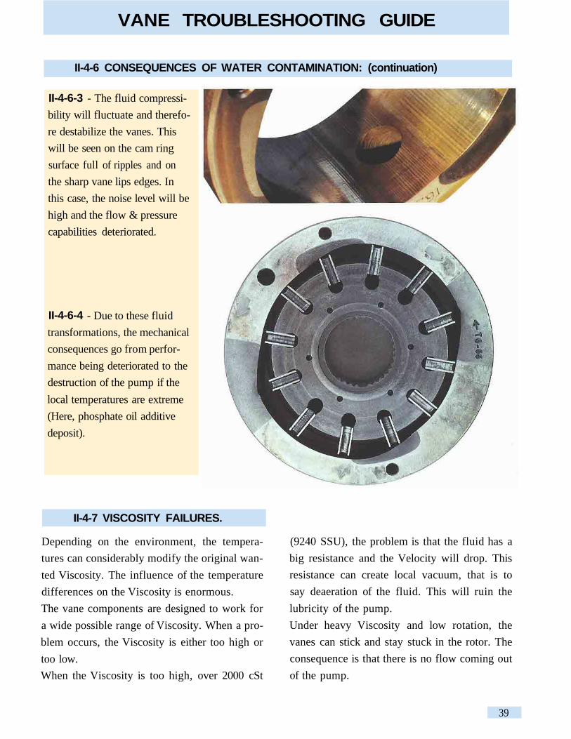
II-4-6-3 - The fluid compressi-
bility will fluctuate and therefo-
re destabilize the vanes. This
will be seen on the cam ring
surface full of ripples and on
the sharp vane lips edges. In
this case, the noise level will be
high and the flow & pressure
capabilities deteriorated.
II-4-6-4 - Due to these fluid
transformations, the mechanical
consequences go from perfor-
mance being deteriorated to the
destruction of the pump if the
local temperatures are extreme
(Here, phosphate oil additive
deposit).
II-4-7 VISCOSITY FAILURES.
Depending on the environment, the tempera-
tures can considerably modify the original wan-
ted Viscosity. The influence of the temperature
differences on the Viscosity is enormous.
The vane components are designed to work for
a wide possible range of Viscosity. When a pro-
blem occurs, the Viscosity is either too high or
too low.
When the Viscosity is too high, over 2000 cSt
(9240 SSU), the problem is that the fluid has a
big resistance and the Velocity will drop. This
resistance can create local vacuum, that is to
say deaeration of the fluid. This will ruin the
lubricity of the pump.
Under heavy Viscosity and low rotation, the
vanes can stick and stay stuck in the rotor. The
consequence is that there is no flow coming out
of the pump.
39

VANE TROUBLESHOOTING GUIDE
II-4-7 VISCOSITY FAILURES.
When the Viscosity is too low, under 8 cSt (52
SSU), it will decrease the film thickness designed
to lubricate all the components in motion. If the
Viscosity is very low, it could mean that the tem-
perature is high. Tests carried out have shown that
a tank temperature of 50°C (122°F) could mean a
local temperature in the pump of up to 130°C
(266°F). If the viscosity is calculated on the tanks
temperature, we can easily figure out the very low
viscosity when the oil is at 130°C (266°F).
II-4-8 CONSEQUENCES OF VISCOSITY FAILURES.
II-4-8-1 - Too high viscosity:
- Seizure due to the high cavita-
tion not allowing the rotating
group to be lubricated.
II-4-8-2 - Too low viscosity:
- Erosion on the port plates.
40

II-4-8 CONSEQUENCES OF VISCOSITY FAILURES: (continuation)
- Scars on the side plates &
rotor due to a bad lubricity.
II-4-9 UNSUITABLE FLUIDS:
Viscosity index choice:
If the fluid was chosen by an OEM in Norway
for a local sale but the application is to work in
Saudi Arabia, the choice of the fluid will have to
take into consideration the specific application
environment.
Forgetting this can lead into deep trouble. Too
high Viscosity will probably cause cavitation
and a lack of lubrication, too low Viscosity will
lead to a too thin film of oil and therefore create
a local heat point.
In both extremes, the consequences can be fatal
breakdowns.
Filterability:
If the fluid does not have good filterability
properties, the filters will be clogged rapidly.
The flow will have to go through the by-pass and
therefore not be filtrated anymore and will heat-up
the system (due to the open by-pass).
Bad filterability can either come from a low qua-
lity fluid, or from a fluid sensitive to any conta-
minant destroying its chemical homogeneity
(water, solvants, grease...).
VANE TROUBLESHOOTING GUIDE
41

VANE TROUBLESHOOTING GUIDE
II-4-9 UNSUITABLE FLUIDS: (continuation)
Oxidation resistance:
Contaminants can modify the acidity of the fluid
and therefore become very corrosive. Such a
modified fluid will corrode the steel components
and produce corrosion residues. These residues
will increase the Viscosity. Increased Viscosity
will increase the pressure drops. Increased pres-
sure drops will then increase the temperature and
cause local overheat.
Deaeration capabilities:
This is another very important topic. If the fluid
chosen requires too long time to allow the air to
reach the surface of the tank, this can become a
big problem. Air in big quantities has a des-
troying effect on all pump technologies. If the
flow versus the size of the tank is small, if the
tank design is incorrect (inlet near return line for
example), if the tank is slightly pressurized (due
on purpose), the oil will not deaerate fast
enough. The air bubbles will then be sucked by
the pump. Under pressure, these bubbles will
then explode.
Polluted fluid:
This is an important topic and, nowadays, well
known at least for the solid particle contamina-
tion. The manufacturing clearances becoming
tighter and tighter, a good filtration is required.
This even though our double lip technology
resists fairly well to pollution.
Another pollution is the impact of another fluid
creating a reaction between the original fluid and
the contaminant. The fluids are more and more
high technical products. They also become more
and more sensitive to their environment and any
contaminant can destroy the original characteris-
tics. It is common for example to see fluids "des-
troyed" by a high water content (chemical, other
fluid, particles). Refined oils will even be more
sensitive than brand new ones.
Density:
It is important to know the specific gravity of the
fluid used. Because the density from one fluid to
another can vary a lot, the suction head has to be
designed with that parameter. The specific gravity
of a standard oil (ISO 46) will be around 0.88.
The specific gravity of a water-glycol (60 glycol/
40 water) will be around 1.08. Knowing this
value, just check the minimum required Absolute
pressure in our catalogs to optimize your system.
42
VANE TROUBLESHOOTING GUIDE
II-4-9 UNSUITABLE FLUIDS: (continuation)
Conclusion on the fluids:
A common problem is the deterioration of the
fluid. This deterioration can come either from the
quality of the fluid (low quality or not used as
recognized fluid manufacturer), or from an exter-
nal pollution, (solid particles, other fluids, che-
mical transformations, water), or from air. The
consequences always lead to a low performing
pump or to a premature breakdown.
II-4-10 Unsuitable grease:
Bad lubricant on the shaft and coupling assem-
bly. We recommend for all grease lubricants to
be based with disulfide of molybdenum. The
main characteristic of this grease is that it is the
best for heavy duty applications. It has a very
good specific load characteristic, avoids stick-
slip and fretting corrosion, has a good penetrabi-
lity and enables easy dismantle.
43

VANE MOTOR
VANE TROUBLESHOOTING GUIDE
44

III SPECIFICS OF VANE MOTOR FAILURES AND CAUSES
Because the motor is a receptor in the hydraulic
circuit, the incidents are not very common. It
will be much easier to go through the various
typical failures you can possibly be confronted
to with vane motors.
III-1 - Torque over the cata-log limits:
Front shaft rupture
Internal splines distortion
45
VANE TROUBLESHOOTING GUIDE

Port block cracked
III-3- Over-pressureon A or B:
Rotor rupture
III-2- Bad air bleedor air intake = incorrect rear
cover lubrication. Possible sei-
zure between the rotor and the
rear cover.
Ill SPECIFICS OF VANE MOTOR FAILURES AND CAUSES (continuation)
VANE TROUBLESHOOTING GUIDE
46

VANE TROUBLESHOOTING GUIDE
III SPECIFICS OF VANE MOTOR FAILURES AND CAUSES (continuation)
III-4- Over-pressure in the drain line:
shaft seal blow off (extruded).
III-5- Excess of Air in thefluid: coming from the system,
coining from an air intake bet-
ween the pump and the motor
or even coming from the front
shaft seal.
- Possible seizure between the
rotor and the rear cover.
- Possible heavy wear on the
port plates.
III-6- Cavitation: the speed of
the motor is higher than the
flow coming to the motor.
Heavy cavitation will lead to
seizure.
47

Ill SPECIFICS OF VANE MOTOR FAILURES AND CAUSES (continuation)
III-7- Pollution.The pollution consequences will
be seen on various areas:
- In the rotor slots
- Grinding on both sides of
the slots.
- Traces of the "spring
areas" of the vanes dig-
ging in.
- On the side of the rotor / port
plates.
- On the vanes
One big particle (welding ball)
and small vertical scars.
- In the came ring
(Scars due to big particles).
VANE TROUBLESHOOTING GUIDE
48

III SPECIFICS OF VANE MOTOR FAILURES AND CAUSES (continuation)
III-8- Too low viscosity:If the temperature rises and the
fluid becomes very "liquid", the
film of oil required to lubricate
the components is going to be
too thin. This can lead to micro-
seizures and to a total seizure if
this film of oil is minor.
The DENISON vane technology is hydrostati-cally balanced, axially and radially. As eachand every single pump, motor or cartridge(sold as spare part) is tested in our productionplant on test benches before shipment, the qua-lity of these components is certified. Our expe-rience has shown us that if :- the inlet characteristics,- the operating limits (pressures, RPM,
Viscosity...)
- the mechanical alignment,
CONCLUSION:
- the fluids' quality (in the time),are in the limits given in the DenisonHydraulics catalogue requirements, you aresure to obtain a high and long performingpump/motor.These few requirements are the major parame-ters to check when working within the cataloguevalues.
VANE TROUBLESHOOTING GUIDE
49

VANE TROUBLESHOOTING GUIDE
IV TROUBLESHOOTING TABLE
This following section is there to help you when
the hydraulic system or component does not work
as required. These solutions are the most common
ones we have seen and experienced in the field.
Please always remember that a clean system and a
correct air bleed will solve a lot of incidents.
51
51
51
54
54
54
55
56
58
58
59
59
59
59
59
60
IV -2 MOTORS
IV -2-1 - No rotation
IV -2-2 - Stalls easily
IV -2-3 - Not enough speed
IV -2-4 - Erratic speed
IV -2-5 - Unusual noise level
IV -2-6 - Unusual heat
IV -2-7 - Shaft seal leakage
IV -1 PUMPS
IV -1-1 - No flow
IV -1-2 - Not enough flow
IV -1-3 - No pressure
IV -1-4 - Not enough pressure
IV -1-5 - Unusual noise level
IV -1-6 - Unusual heat
IV -1-7 - Shaft seal leakage
50

IV -1 TROUBLESHOOTING TABLE FOR PUMPS
IV-1-1 - No flow,
no pressure
f) Is the pump flow not
going somewhere else?
f-1) Check the hydraulic circuit and the main
sequences. Doing so, you will check if all the valves
are set or work properly.
e) Is the Viscosity not
too high?
e-1) Check if the oil characteristics are not incompa-
tible with the temperature and the pumps require-
ments. Too high Viscosity will "stick" the vein fluid
and enable the pump to suck the oil correctly.
d) How are the inlet
conditions?
d-1) Check if the inlet gate valve is not closed.
d-2) Check the oil level.
d-3) Check if the inlet hose in the tank is under the oil
tank level.
d-4) Check if an air intake is not disturbing the inlet
(missing inlet flange seal, air trapped in suction line as
examples).
d-5) Check if the pump is not located too high above
the oil level.
d-6) Check if the tank is not completely sealed. Then
the lack of atmospheric pressure will not allow the
pump to prime.
d-7) Check if all connections and seals are air-tight.
c) Is the air bleed-off
done?
c-1) Check that no air is still located in the pressure
line. Loosen a connector.
b) Is the rotation in the
correct direction?
b-1) Check if the rotation of the pump corresponds to
the arrow on the name plate.
b-2) Check if the wiring of the electric motor is cor-
rect.
a) Is the pump rotating ? a-1) Check if the coupling is rotating. If not, check the
rotation of the electric motor.
a-2) Check the keys of the pump and E motor shaft.
a-3) Check if the shaft is not broken.
VANE TROUBLESHOOTING GUIDE
51

b) Is the connection from
the tank to the pump cor-
rect?
b-1) Check if there is no air intake between the pump
and the inlet pipe (bad seals for example).
b-2) Check if the inlet hose is convenient for the requi-
red velocity (0,5 < V < 1,9 m/s).
IV-1-2 -
Not enough flow
(or not the flow
required)
a) Are the components
OK?
a-1) Check the displacement of the pump.
a-2) Check if the speed of the pump is not too low or
too high (E motor or thermic engine sized too small so
dropping the speed too low...).
a-3) Check if the main relief valve is not set at an
extremely low pressure and therefore venting some
flow back to the tank.
a-4) Check if in the directional valves the spools are
not sticking in a position that brings part of the flow
back to the tank.
a-5) Check if the hydraulic motor is not leaking inter-
nally due to a bad efficiency, low viscosity...
a-6) Check if the cylinder inner seals are not ruined
and therefore allow internal leakage.
g) Is the receptor wor-
king correctly?
h) Is the speed high
enough?
f-2) Check if the main relief valve is not set at an
extremely low pressure and therefore bringing all the
flow back to the tank.
f-3) Check if in the directional valves the spools are
not sticking in a position that brings the flow back to
the tank.
f-4) check if the check valve is not mounted "upside
down".
g-1) Check if the motor does not let all the flow leak
internally.
g-2) Check if the cylinder inner seals are not ruined.
h-1) Check if the minimum speed is reached.
Mobile pumps require 400 rpm and industrial
pumps require 600 rpm.
f) Is the pump flow notgoing somewhere else ?
(continuation)
IV-1-1 - No flow,
no pressure
(continuation)
IV -1 TROUBLESHOOTING TABLE FOR PUMPS (continuation)
VANE TROUBLESHOOTING GUIDE
52

d) Is the oil convenient? d-1) Check if the oil characteristics are not incompa-
tible with the pumps requirements.
d-2) Check if the viscosity is not too high, therefore
"sticking" some vanes in the rotor or blocking the vein
fluid.
d-3) Check if the high temperature does not destroy
the viscosity of the fluid. Doing so, the internal leaka-
ge will "consume" the flow.
c) Is the tank design cor-
rect?
c-1) Check if the oil level is correct.
c-2) Check if the suction pipe is under the oil level
during the complete cycle of the machine.
c-3) Check if the inlet hose fitted in the tank is cut
with an angle wider than 45°.
c-4) Check if this inlet hose is not too close to the tank
wall or to the bottom of the tank and therefore limits
the "vein flow".
c-5) Check if the suction hose is not located near the
return line and therefore sucking a lot of air coming
from these turbulences.
c-6) Check if baffles are required to allow correct dea-
reation of the fluid.
c-7) Check if the air filter is not clogged or under sei-
zed (not well dimensioned).
c-8) Check if the tank is not fully tight, not allowing
the atmospheric pressure to apply.
IV-1-2 -
Not enough flow
(or not the flow
required)
(continuation)
b) Is the connection from
the tank to the pump cor-
rect? (continuation)
b-3) Check if the pump is not too high compared to
the oil level or if the pump is not too far from the tank
(check the inlet absolute pressure with the catalog
values).
b-4) Check if the gate valve is not semi-open.
b-5) Check if the inlet strainer is sized correctly (250
m mesh mini.) or not clogged.
IV -1 TROUBLESHOOTING TABLE FOR PUMPS (continuation)
VANE TROUBLESHOOTING GUIDE
53

IV-1-5 -
Uncommon noise
level
a) Is the noise coming
from the pump?
a-1) Check the mechanical link of the shaft pump : ali-
gnment, balancing of the coupling or Universal joint,
key properly fastened, ...
a-2) Check if the air bleed has been done correctly.
a-3) Check if there is no air intake from the tank to the
pump (nor through the shaft seal).
IV-1-4 -
Not enough
pressure
a) Check as when "no
pressure" IV-1-3.
b) Is the system well
dimensioned?
c) Is there an internal
leakage somewhere that
maintains a certain pres-
sure?
c-1) Check all the possible faulty components, from
the pump to all the receptors and intermediates (high
pressure seals, mechanical wear...).
b-1) Check if the flow required is not over the avai-
lable flow and therefore cannot build-up pressure..
c) Are the components
working properly?
b) Is the circuit correctly
piped?
b-1) Compare the schematic to the piped circuit.
c-1) Check the main sequences. Doing so, you will
check if all the valves are set or work properly.
c-2) Check if the main relief valve is not set at an
extremely low pressure and therefore bringing all the
flow back to the tank.
c-3) Check if in the directional valves the spools are
not sticking in a position that brings the flow back to
the tank.
IV-1-3-
No pressure
a) Is the hydraulic circuit
correctly designed?
a-1) Check the hydraulic circuit schematic.
IV -1 TROUBLESHOOTING TABLE FOR PUMPS (continuation)
VANE TROUBLESHOOTING GUIDE
54

IV-1-6 -
Unusual heat
level
a) Does the heat appear
when the pump is run-
ning without pressure?
a-1) Check the oil level and the suction pipe. Is the oil
coming to the pump (check the length of the pipe, its
internal diameter, all that could influence the inlet
pressure)?
a-2) Check if the air bleed has been done correctly.
a-3) Check if the flow versus the volume of oil in the
tank is correct to obtain a good cooling effect.
b) Is the noise coming
from the surroundings?
b-1) Check the hoses and see if the noise in not
coming back to the pump this way.
b-2) Check the pressure piping and see if its length
dumps or amplifies the noise.
b-3) Check if the structure of the tank is stiff enough
to avoid amplification/resonance.
b-4) Check the E motor fan.
b-5) Check the balancing of the E motor.
b-6) Check the water cooler and its theoretical limits.
b-7) Check the filtration unit, its capacity and if the
noise does not come from the opened by-pass valve.
IV-1-5 -
Uncommon noise
level
(continuation)
a) Is the noise coming
from the pump?
(continuation)
a-5) Check if the hose strain force does not create this
noise.
a-6) Check if the oil level is correct.
a-7) Check if the oil in the tank is not aerated.
a-8) Check if the strainer is not clogged or under-
dimensioned.
a-9) Check if the inlet pipe is under the oil level.
a-10) Check if the air filter is not clogged or too small.
a-11) Check if the speed is not incompatible with the
catalog values.
a-12) Check if the oil is compatible with the catalog
recommendations.
a-13) Check if the inlet pressure is not higher than the
outlet pressure.
IV -1 TROUBLESHOOTING TABLE FOR PUMPS (continuation)
VANE TROUBLESHOOTING GUIDE
55

IV-1-6 -Unusual heat
level
(continuation)
a) Does the heat appearwhen the pump is run-
ning without pressure?
(continuation)
a-4) Check if a cooler is required or, if there is one, if
it is well dimensioned.
a-5) If there is a cooler, check if it is working
(example for water cooler: is the water flow open or
sufficient).
a-6) Check if the hydraulic circuit is not bringing back
the flow directly to the inlet port. Doing so, it would
create a very small closed circuit not able to cool
down the fluid.
a-7) Check the quality of the fluid.
a-8) Check the velocity of the fluid.
a-9) Check the filtration unit, its capacity and if the
heat does not come from the open by-pass valve or if
it is under-dimensioned (bigger delta P).
b) Does the heat appear
when the pump is run-
ning with pressure?
b-1) Check the viscosity.
b-2) Check the pressure rating.
b-3) Check if the cooler is working correctly or well
dimensioned.
b-4) Check if the relief valve is not creating this heat
because always open.
b-5) Check if any other component in the system is
not creating this heat due to an internal defect.
b-6) Check if there is a big temperature differential
between the inlet and the outlet.
IV-1-7 -
Shaft seal leakage
a) Is the seal destroyed? a-1) Check the alignment and the correct power trans-
mission (non homokinetic movement, high radial
force as examples).
a-2) Check the inlet pressure and compare it to the
catalog values.a-3) Check if the bad suction conditions do not create
a vacuum that could even reverse the seal lip.
IV -1 TROUBLESHOOTING TABLE FOR PUMPS (continuation)
VANE TROUBLESHOOTING GUIDE
56

IV-1-7 -
Shaft seal leakage(continuation)
a) Is the seal destroyed?(continuation)
b) Is the seal only lea-king?
a-4) Check if the external environment is not too dirtyand therefore ruining the seal.
b-1) Check the alignment of the front shaft and check
if there is not any radial load.
b-2) Check if seal lip has not been cut during a main-tenance operation.
b-3) Check if the inlet pressure is not over or under the
catalog values. This has to be done for the whole cyclebecause the inlet pressure can vary from time to time.
b-4) Check if the seal material has not been modifieddue to a too warm environment. The seal can vulcani-
ze and stop sealing correctly.
b-5) Check the acidity of the oil that can "burn" theseals material. It will therefore destroy the elasticity ofthe sealing.b-6) Check if the chosen seal (high pressure seal for
example) is not too stiff for the use. If the environment
requires some elasticity due to a gentle misalignment,
a high pressure seal will not be able to follow themovement and therefore leak.
IV -1 TROUBLESHOOTING TABLE FOR PUMPS (continuation)
VANE TROUBLESHOOTING GUIDE
57

IV-2-2 -Stalls easily
a) Is the load near thelimits of the system?
a-1) Check the relief valve setting and compare it tothe theoretical pressure required to deliver the conve-nient torque.
b) Are the motors inter-nal drain check valvesworking properly?
b-1) Check if a failing check valve would not allowsome flow to go back to the tank and therefore limitthe flow to the motor.
c) Is the flow going tothe motor sufficient?
c-1) Check the minimum flow required by the motor.c-2) Check the flow of the pump or the valve feedingthe motor.
e) How is the motorpiped?
d) Are the motors inter-nal drain check valvesworking properly?
c) Is the pump OK? c-1) Check if the pump is working correctly.
d-1) Check if a failing check valve would not allowsome flow to go back to the tank and therefore limitthe flow to the motor.
e-1) Check the nature of the connectors. If, forexample, the "self sealing couplings" type connectorsare well fitted into each other.
b) Is the torque requiredhigher than the systemsettings?
b-1) Check if the pressure settings are correct.b-2) Check if the load is not superior to the torquecapabilities of the motor.
a-1) Check the circuit and the hydraulic schematic. Isthe piping OK?a-2) Check the setting of the main pressure relief valve.Check if it not settled at an extremely low pressure.a-3) Check if the pump is giving a flow.a-4) Check if the directional valve(s) allowing theflow to go to the motor is energized. If it is, check ifthe spool is in its correct position and not sticking in aposition that would deviate the flow somewhere else.a-5) Check if a check valve would not have beenimproperly mounted.
a) Is the flow coming tothe motor?
IV-2-1 -No rotation
IV -2 TROUBLESHOOTING TABLE FOR MOTORS
58
VANE TROUBLESHOOTING GUIDE

IV -2 TROUBLESHOOTING TABLE FOR MOTORS (continuation)
IV-2-3 -Not enough speed
a) Is the speed lowerthan desired?
a-1) Check the theoretical displacement of the motorversus the theoretical flow of the pump.a-2) Check that the flow of the pump is really comingto the motor.a-3) Check that the working pressure & speed are notincompatible with the catalog values of the motor.a-4) Check the oil temperature. Check then that thelow viscosity of the oil is not having a big effect on theinternal leakage of the motor.a-5) Check the air bleed-off.
IV-2-4 -
speedErratic a) Is the motor loosing
speed erratically?a-1) Check if the limit of the allowable torque is notreached once a while.a-2) Check if the driven load does not transmit someinconstant load (high pressure piston water pumpswith an unbalanced technology).a-3) Check if the flow coming from the pump is constant.
IV-2-5 - Unusualnoise level
a) Is the motor running? a-1) Check if there is no air intake aerating the motorbadly (through the front shaft seal for example).a-2) Check if the motor is not cavitating. It could bethat the inertia of the load is such that it drives themotor faster than the flow coming from the pump.a-3) Check if the oil is not proper for the use.a-4) Check if the air bleed has been done properly.b-1) Check the back pressure to see if the replenish-ment pressure is not too low, leading to cavitation ofthe motor.
b) When the motor isbreaking?
IV-2-6 -Unusual heat
a) Is the oil arriving tothe motor already hot?
a-1) Check if a cooler is required or if there is one ifit is well dimensioned.a-2) If there is a cooler, check if it is working(example for water cooler: is the water flow opened orsufficient).a-3) Check if the hydraulic circuit is not bringing backthe flow directly to the inlet port. Doing so, it wouldcreate a very small closed circuit not able to cooldown the fluid.
59
VANE TROUBLESHOOTING GUIDE

b) Is the seal leakingwhen standing still?
a-1) Check if the seal is not damaged.a-2) Check if the shaft does not have any scratches.a-3) Check if the ball bearing is not ruined.a-4) Check if the drain line does not create a back pressure.
IV-2-7 -
Shaft seal leakagea) Is the seal leakingwhen pressurized?
a-1) Check if the lips of the seal are not ruined (lackof lubricity leading to vulcanization of the rubber,external pollution...).a-2) Check if the shaft is not marked by a groove inthe usual seal lip contact area.a-3) Check the shuttle valves.a-4) Check the pressure in the drain line on the motor.Long piping, elbows, small diameter, too high oil vis-cosity, other common drain flows in the same pipe canlead to high drain pressures.
a-5) Check if there is no high overshoot at start-up thatwould create a high instant internal leakage.a-6) Check, when using a "rapid connector", if it iswell locked.a-7) Check the alignment of the shafts.a-8) Check if there is no unbalanced driven load thatcould create a gap between the shaft and the seal.a-9) Check if the radial force is not too high (beltdrives for example).
b) Is the oil heating upwhen going through themotor?
b-1) Check the speed of rotation versus the catalog values.b-2) Check the pressure rating.
b-3) Check the fluid.b-4) Check the viscosity.
IV-2-6 -
Unusual heat
(continuation)
a) Is the oil arriving tothe motor already hot?
(continuation)
a-4) Check the quality of the fluid.a-5) Check the velocity of the fluid (5 to 6meters/second max.).a-6) Check the filtration unit, its capacity.a-7) Check if the heat does not come from an open by-pass valve.
60
IV -2 TROUBLESHOOTING TABLE FOR MOTORS (continuation)
VANE TROUBLESHOOTING GUIDE

Printed in France IRO - La Rochelle Change without notice reserved
INTERNET: http ://www.denisonhydraulics.com
Your local DENISON representative
International DistributorsIn Europe:CyprusEastern EuropeThe Faroe IslandsGreeceIcelandNorwayPortugalSwitzerlandTurkey
In Africa :AlgeriaEgyptIvory CoastMoroccoNigeriaSouth AfricaTogoTunisia
In Middle East :IranIsraelLebanonPakistanQatarSaudi ArabiaSyriaUnited Arab Emirates
In Far East :ChinaIndonesiaKoreaMalaysiaNew ZealandPhilippinesThailand
AustraliaDENISON HYDRAULICSAUSTRALIA PTY Ltd.41-43 St.Hilliers RoadP.O. Box 192Auburn N.S.W. 2144AustraliaTel. (02) 9646 5200Fax (02) 9643 1305
Other sales offices :VictoriaQueenslandWestern Australia
AustriaDENISON HYDRAULIK GmbHZweigniederlassung LinzHaidbachstraße 69A-4061 PaschingAustriaTel. (0 72 29) 48 87Fax (0 72 29) 6 30 92
BeneluxDENISON HYDRAULICSBENELUX B.V.Pascalstraat 1003316 GR DordrechtHollandTel. (078) 179 900Fax (078) 175 755
CanadaDENISON HYDRAULICSCANADA Inc.2320-1 Bristol Circle, Unit 1Oakville, ON L6H 5S2CanadaTel. (905) 829 5800Fax (905) 829 5805
Other sales offices :Montreal, QCCalgary, AL
DenmarkDENISON HYDRAULIKDANMARK A/SIndustrikrogen 2DK-2635 IshöjDenmarkTel. (4371) 15 00Fax (4371) 15 16
FinlandDENISON HYDRAULICSP.O. Box 36FIN-08101 LohjaFinlandTel. (358) 208 333 045Fax (358) 207 333 045
FranceDENISON HYDRAULICSFRANCE SA14, Route du Bois BlancBP 53918105 VierzonFranceTel. 02 48 53 01 20Fax 02 48 75 02 91
Other sales offices :BordeauxLyonParis
GermanyDENISON HYDRAULIK GmbHHerderstrasse 26D-40721 HildenGermanyTel. (0 21 03) 940 600Fax (0 21 03) 940 888
Other sales offices :DresdenHannoverStuttgart
Great BritainDENISON HYDRAULICS U.K. LtdKenmore RoadWakefield 41, Industrial ParkWakefield, WF2 OXEWest YorkshireEnglandTel. (19 24) 826 021Fax (19 24) 826 146
Other sales office :Burgess Hill
Hong KongDENISON HYDRAULICS LtdUnit 2, 25/F Wharf Cable Tower9 Hoi Shing RoadTsuen WanNT., Hong KongTel. 2498 8381Fax 2499 1522
ItalyDENISON HYDRAULICSITALY S.r.l.Via le Europa 6820090 Cusago (Ml) MilaneseItalyTel. (02) 90330-1Fax (02) 90390694/5/6
JapanDENISON JAPAN INC.4-2-1 TSUJIDO-SHINMACHIFujisawa251JapanTel. (466) 35-3050Fax (466) 35-2019
Other sales offices :Osaka
Mexico, central America,South America and CaribbeanCountries ContactDENISON HYDRAULICS Inc.6167 NW 181 Terrace CircleNorthMiami, FL 33015Tel. 305 362 2246Fax 305 362 2246
P.R.ChinaDENISON HYDRAULICS Ltd3F, No. 1, Mao Jia Zhai, Bai Lian JingPudong New AreaShanghai 200126ChinaTel. 86 21 58868991Fax 86 21 5886 1978
SingaporeDENISON HYDRAULICS S.E.A.Pte.Ltd.11 Lorong Tukang DuaSingapore 2261Tel. 268 78 40Fax 268 78 47
SpainDENISON HYDRAULICS, S.A.Gomis 108023 BarcelonaSpainTel. (93) 418 46 87Fax (93) 211 65 07
Other sales office :San Sebastian
SwedenDENISON HYDRAULICSSVENSKA ABSporregatan 1321377 - MalmöSwedenTel. (40) 210440Fax (40) 214726
Other sales office :Järfälla
USADENISON HYDRAULICS Inc.14249 Industrial ParkwayMarysville, OH 43040USATel. (937) 644 3915Fax (937) 642 3738For nearest distributorCall Toll Free 1 800 551 5956
Email :[email protected]
Other European, Middle Eastand African CountriesContactDENISON HYDRAULICSFRANCE SA14, route du Bois BlancBP 53918105 Vierzon CedexFranceTel. 02 48 53 01 20Fax 02 48 53 01 46
SALES & SERVICES WORLDWIDE
DENISON Hydraulics