Embed Size (px)
Citation preview
Demystifying Explosives:Concepts in High Energy Materials
S. VenugopalanFormer scientist,
High Energy Materials Research Laboratory,Pune, India
AMSTERDAM BOSTON HEIDELBERG LONDON NEW YORK OXFORD
PARIS SAN DIEGO SAN FRANCISCO SINGAPORE SYDNEY TOKYO

This page intentionally left blank
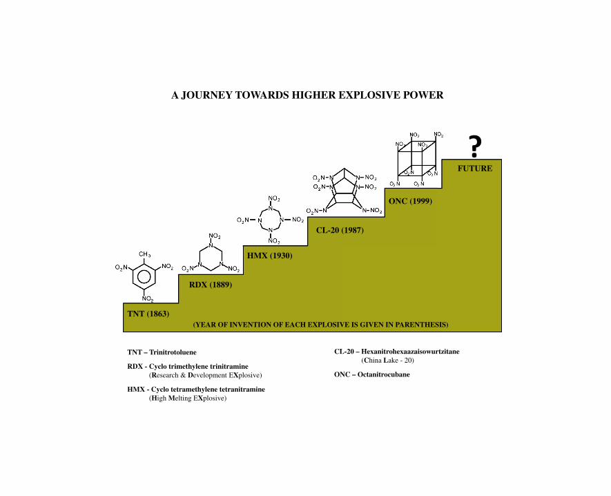
TNT (1863)
RDX (1889)
HMX (1930)
CL-20 (1987)
ONC (1999)
FUTURE
?
(YEAR OF INVENTION OF EACH EXPLOSIVE IS GIVEN IN PARENTHESIS)
TNT – Trinitrotoluene
RDX - Cyclo trimethylene trinitramine(Research & Development EXplosive)
HMX - Cyclo tetramethylene tetranitramine(High Melting EXplosive)
CL-20 – Hexanitrohexaazaisowurtzitane(China Lake - 20)
ONC – Octanitrocubane
A JOURNEY TOWARDS HIGHER EXPLOSIVE POWER

ElsevierRadarweg 29, PO Box 211, 1000 AE Amsterdam, NetherlandsThe Boulevard, Langford Lane, Kidlington, Oxford OX5 1GB, UK225 Wyman Street, Waltham, MA 02451, USA
Copyright © 2015 Elsevier Inc. All rights reserved.
No part of this publication may be reproduced or transmitted in any form or by any means, electronic ormechanical, including photocopying, recording, or any information storage and retrieval system, withoutpermission in writing from the publisher. Details on how to seek permission, further information about thePublisher’s permissions policies and our arrangements with organizations such as the Copyright ClearanceCenter and the Copyright Licensing Agency, can be found at our website: www.elsevier.com/permissions.
This book and the individual contributions contained in it are protected under copyright by the Publisher(other than as may be noted herein).
NoticesKnowledge and best practice in this field are constantly changing. As new research and experience broadenour understanding, changes in research methods, professional practices, or medical treatment may becomenecessary.
Practitioners and researchers must always rely on their own experience and knowledge in evaluating and usingany information, methods, compounds, or experiments described herein. In using such information or methodsthey should be mindful of their own safety and the safety of others, including parties for whom they have aprofessional responsibility.
To the fullest extent of the law, neither the Publisher nor the authors, contributors, or editors, assume anyliability for any injury and/or damage to persons or property as a matter of products liability, negligence orotherwise, or from any use or operation of any methods, products, instructions, or ideas contained in thematerial herein.
British Library Cataloguing in Publication DataA catalogue record for this book is available from the British Library
Library of Congress Cataloging-in-Publication DataA catalog record for this book is available from the Library of Congress
ISBN: 978-0-12-801576-6
For information on all Elsevier publicationsvisit our web site at http://store.elsevier.com
Front cover photograph: Controlled explosion of unexploded ordnance. Courtesy: The U.S. Department ofDefense (DISCLAIMER: The use of military imagery does not imply or constitute endorsement of the authoror his services by the U.S. Department of Defense)

The author dedicates this book to the memory of countless number ofinnocent human beings who lost their lives in terrorist explosions all over the
world with the prayer that this planet will be free from the clutches ofterrorism in the near future.
High energy materials (HEMs; explosives, propellants, and pyrotechnics) arevery dangerous if they are not handled with care and caution. In my careerspanning over three decades, I have witnessed gruesome accidents, some of
them fatal, at almost every stage, synthesis, scale-ups, production, testing, andeven waste disposal of HEMs. The victims of those accidents include notonly the beginners who were ignorant but also veterans who wereeither overconfident or complacent. Odds are highly against you whenHEMs are handled with disregard for standard operating procedures (SOPs)and the “Dos and Don’ts.” Read Chapter 8 on safety for more details.
Remember that like fire and electricity, HEMs can be your best friend or worstenemy depending on how you handle them.

This page intentionally left blank
Contents
About the Author and Editor ............................................................................ xiii
Foreword 1 ...................................................................................................... xv
Foreword 2 .................................................................................................... xvii
Foreword 3 ..................................................................................................... xix
Preface ........................................................................................................... xxi
Acknowledgments ...........................................................................................xxiii
Abbreviations ..................................................................................................xxv
Chapter 1: In Pursuit of Energy and Energetic Materials....................................... 11.1 Introduction ............................................................................................................ 11.2 Gunpowder to Nitrocubanes .................................................................................. 11.3 Classification of Explosives................................................................................... 6
1.3.1 Maximum Power per Unit Volume ................................................................... 61.3.2 High Velocity of Detonation ............................................................................. 61.3.3 Long-Term Storage Stability ............................................................................. 71.3.4 Insensitivity to Shock and Impact ..................................................................... 71.3.5 Ability to Withstand Large Accelerations ........................................................ 7
1.4 Explosives and Molecular Structure...................................................................... 81.5 Classification of Propellants .................................................................................. 8
1.5.1 Small-Arms Propellant..................................................................................... 101.5.2 Mortar Propellant ............................................................................................. 101.5.3 Gun Propellant ................................................................................................. 101.5.4 Rocket Propellant............................................................................................. 11
1.6 Pyrotechnics ......................................................................................................... 111.6.1 Light ................................................................................................................. 141.6.2 Smoke............................................................................................................... 141.6.3 Sound................................................................................................................ 141.6.4 Heat .................................................................................................................. 14
Appendix A................................................................................................................. 15Appendix B................................................................................................................. 16Appendix C................................................................................................................. 16Suggested Reading ..................................................................................................... 17Questions .................................................................................................................... 17
vii
Chapter 2: Energetics of Energetic Materials ..................................................... 192.1 Are Explosives and Propellants High-Energy Materials? .................................. 192.2 Explosive: The Wonderful Lamp ........................................................................ 202.3 Thermochemistry and Explosive Energy ............................................................ 22
2.3.1 Heat of Reaction .............................................................................................. 232.3.2 Heat of Formation............................................................................................ 232.3.3 Heat of Explosion (DHe) and Heat of Combustion (DHc)............................. 272.3.4 Oxygen Balance ............................................................................................... 29
Worked Example 2.1 .................................................................................................. 322.3.5 Heat of Explosion: Dependence on Heat of Formation and
Oxygen Balance ............................................................................................. 332.3.6 OB of Composite Explosives ........................................................................ 342.3.7 Hazard Assessment from OB ........................................................................ 352.3.8 Composition of Gaseous Products ................................................................ 352.3.9 Significance and Limitations of OB.............................................................. 36
2.3.10 Detonation Temperature/Flame Temperature................................................ 37Worked Example 2.2 .................................................................................................. 39
2.3.11 Gas Volume .................................................................................................... 42Worked Example 2.3 .................................................................................................. 42
2.3.12 The nRT Wonder............................................................................................ 43Worked Example 2.4 .................................................................................................. 44
2.3.13 Pressure of Explosion .................................................................................... 452.3.14 Density............................................................................................................ 45
Summary of Important Terms.................................................................................... 46Suggested Reading ..................................................................................................... 48Questions .................................................................................................................... 49
Chapter 3: Two Faces of Explosion: Deflagration and Detonation......................... 513.1 Explosion.............................................................................................................. 513.2 Deflagration and Detonation................................................................................ 523.3 Linear Burning and Mass Burning...................................................................... 543.4 Shock Wave and Detonation Wave ..................................................................... 55
3.4.1 The Concept of a Shock Wave........................................................................ 563.4.2 Detonation Wave.............................................................................................. 58
3.5 Detonation Theory ............................................................................................... 603.6 Theoretical Estimation: VOD and Pd.................................................................. 62
3.6.1 KamleteJacob Method .................................................................................... 623.6.2 Becker-Kistiakowsky-Wilson Method............................................................. 643.6.3 Rothestein and Petersen Method ..................................................................... 653.6.4 Stine Method .................................................................................................... 67
3.7 Deflagration-to-Detonation Transition................................................................. 673.7.1 When Can DDT Occur? .................................................................................. 67
Suggested Reading ..................................................................................................... 68Questions .................................................................................................................... 69
Contents
viii
Chapter 4: HEMs: The Facet of Explosive Performance ...................................... 714.1 Why Do Explosives Explode?............................................................................. 71
4.1.1 Spontaneity of Explosive Reactions................................................................ 714.1.2 The Kinetic Aspect of Explosive Reactions ................................................... 724.1.3 Molecular Structure and Explosive Properties................................................ 74
4.2 Two Aspects of Explosive Performance ............................................................. 774.2.1 Partition of Explosive Energy ......................................................................... 774.2.2 Velocity of Detonation..................................................................................... 784.2.3 Gas Expansion.................................................................................................. 79
4.3 A Travel by Explosive Train................................................................................ 814.3.1 Primary Explosives: “the engine starters in an explosive train!” ................. 814.3.2 Secondary Explosives: “the final operators of the explosive train!” ............. 834.3.3 The Types of Explosive Trains........................................................................ 86
4.4 Performance Parameters of Military Explosives................................................. 874.4.1 Fragmentation................................................................................................... 874.4.2 Scabbing ........................................................................................................... 884.4.3 Shaped Charge Penetration.............................................................................. 894.4.4 Blast.................................................................................................................. 91
4.5 Industrial Explosives ............................................................................................ 944.5.1 Introduction ...................................................................................................... 944.5.2 Requirements of Industrial Explosives............................................................ 954.5.3 Industrial High Explosives............................................................................... 964.5.4 Blasting Agents ................................................................................................ 97
4.6 Processing of the Compositions ........................................................................ 1004.6.1 Melt-Casting................................................................................................... 1004.6.2 Pressing .......................................................................................................... 1014.6.3 Plastic Bonded Explosives (PBX) ................................................................. 101
Suggested Reading ................................................................................................... 102Questions .................................................................................................................. 103
Chapter 5: The Propulsive Facet of HEMs: I (Gun Propellants)......................... 1055.1 Introduction ........................................................................................................ 1055.2 Gun: the Heat Engine ........................................................................................ 105Worked Example 5.1 ................................................................................................ 1075.3 Unfolding Drama inside the Barrel ................................................................... 1085.4 Energetics of Gun Propellant ............................................................................ 110Worked Example 5.2 ................................................................................................ 1125.5 Configuration of Propellant Grains ................................................................... 112
5.5.1 Regressive Burning ........................................................................................ 1145.5.2 Neutral Burning.............................................................................................. 1145.5.3 Progressive Burning ....................................................................................... 114
5.6 Salient Aspects of Internal Ballistics of Guns.................................................. 116Worked Example 5.3 ................................................................................................ 117
Contents
ix
5.7 The Chemistry of Gun Propellant Formulations .............................................. 1205.7.1 Role of Ingredients ........................................................................................ 123
Worked Example 5.4 ................................................................................................ 125Suggested Reading ................................................................................................... 131Questions .................................................................................................................. 131
Chapter 6: The Propulsive Facet of High Energy MaterialsdII(Rocket Propellants) ...................................................................................... 133
6.1 Introduction to Rocketry.................................................................................... 1336.2 Basic Principles of Rocket Propulsion.............................................................. 133
6.2.1 Types of Rocket Engines ............................................................................... 1356.3 Specific Impulse ................................................................................................. 138
6.3.1 The Unit of Isp ............................................................................................... 1386.3.2 Isp and Exhaust Velocity of Gases ................................................................ 139
Worked Example 6.1 ................................................................................................ 1396.4 Thermochemistry of Rocket Propulsion............................................................ 1406.5 Some Vital Parameters in the Internal Ballistics of Rockets ........................... 142
6.5.1 Linear Burning Rate ...................................................................................... 1426.5.2 Characteristic Velocity ................................................................................... 144
6.6 Design of a Rocket Propellant Grain ................................................................ 145Worked Example 6.2 ................................................................................................ 1466.7 Chemistry of Solid Rocket Propellants ............................................................. 147
6.7.1 Choices and Limitations ................................................................................ 1476.8 Future of Rocket Propellants ............................................................................. 153Suggested Reading ................................................................................................... 154Questions .................................................................................................................. 154
Chapter 7: High Energy Materials in Pyrotechnics ............................................ 1577.1 Introduction ........................................................................................................ 1577.2 Applications........................................................................................................ 1577.3 Basic Principles of Pyrotechnics ....................................................................... 159
7.3.1 The Chemical Components of Pyrotechnics................................................. 1597.3.2 Factors Affecting the Performance of Pyrotechnics ..................................... 1617.3.3 Safety Aspects Involving Pyrotechnics ......................................................... 162
7.4 Conclusion.......................................................................................................... 163Suggested Reading ................................................................................................... 163Questions .................................................................................................................. 163
Chapter 8: HEMs: Concerns of Safety............................................................. 1658.1 Introduction ........................................................................................................ 1658.2 Nature of Hazards .............................................................................................. 1658.3 Hazard Classification of HEMs......................................................................... 1668.4 The Damages...................................................................................................... 1678.5 General Safety Directives .................................................................................. 168
8.5.1 Assume the Hazard ...................................................................................... 1688.5.2 Never Work Alone!...................................................................................... 168
Contents
x
8.5.3 Start with the Smallest Possible Quantities ................................................ 1688.5.4 Safety Shields............................................................................................... 1688.5.5 Fire Hazards: Expect and be Ready............................................................ 1688.5.6 Ground (Earth) Your Facilities .................................................................... 1688.5.7 Wear Protective Garments/Equipments (Including Antistatic Ones) ......... 1698.5.8 Practice Relative Humidity Control ............................................................ 1698.5.9 Housekeeping ............................................................................................... 169
8.5.10 Know about the Material Hazards .............................................................. 1698.5.11 Toxic Hazards .............................................................................................. 1698.5.12 Prepare a Work Plan .................................................................................... 1708.5.13 Hazard Evaluation........................................................................................ 1708.5.14 Storage/Transport ......................................................................................... 1708.5.15 Waste Disposal ............................................................................................. 172
8.6 Conclusion.......................................................................................................... 172Suggested Reading ................................................................................................... 172Questions .................................................................................................................. 172
Chapter 9: HEMs: Concerns of Security .......................................................... 1739.1 HEMs: Concerns of Security............................................................................. 1739.2 Detection of Explosives ..................................................................................... 174
9.2.1 Electron Capture Detector ............................................................................. 1759.2.2 Ion Mobility Spectrometer............................................................................. 1769.2.3 Thermoredox Detector ................................................................................... 1769.2.4 Field Ion Spectrometer .................................................................................. 1779.2.5 Diamagnetism-Based Magnetic Field Detector ............................................ 1779.2.6 Nuclear Quadrupole Resonance Detector ..................................................... 1779.2.7 Micro Electro Mechanical Systems............................................................... 178
Suggested Reading ................................................................................................... 179Questions .................................................................................................................. 179
Chapter 10: HEMs: Characterization and Evaluation........................................ 18110.1 Introduction ...................................................................................................... 18110.2 Chromatographic Techniques .......................................................................... 182
10.2.1 Thin Layer Chromatography ..................................................................... 18210.2.2 Gas Chromatography ................................................................................. 18210.2.3 High Performance Liquid Chromatography.............................................. 183
10.3 Spectroscopic Techniques ................................................................................ 18410.3.1 UV/VIS Spectroscopy................................................................................ 18410.3.2 IR Spectroscopy ......................................................................................... 18410.3.3 Nuclear Magnetic Resonance Spectroscopy ............................................. 185
10.4 Thermal Evaluation of Energetic Materials .................................................... 18610.4.1 Differential Thermal Analysis ................................................................... 18710.4.2 Differential Scanning Calorimetry ............................................................ 18710.4.3 Thermogravimetric Analysis ..................................................................... 18910.4.4 Simultaneous Thermal Analysis ................................................................ 191
Contents
xi

10.5 Sensitivity Tests of HEMs ............................................................................... 19110.5.1 Impact Sensitivity ...................................................................................... 19210.5.2 Friction Sensitivity ..................................................................................... 19210.5.3 Spark Sensitivity ........................................................................................ 192
Suggested Reading ................................................................................................... 193Questions .................................................................................................................. 193
Chapter 11: HEMs: Trends and Challenges ..................................................... 19511.1 Introduction ...................................................................................................... 19511.2 Primary Explosives .......................................................................................... 195
11.2.1 Problems..................................................................................................... 19511.2.2 Solutions..................................................................................................... 195
11.3 High Explosives ............................................................................................... 19611.3.1 High-Density, High-VOD Explosives........................................................ 19711.3.2 Insensitive High Explosives....................................................................... 199
11.4 Propellants ........................................................................................................ 20211.4.1 Ecofriendly Oxidizers ................................................................................ 20211.4.2 Metallic Fuels............................................................................................. 20411.4.3 Energetic Binders....................................................................................... 20511.4.4 Thermoplastic Elastomers.......................................................................... 20611.4.5 Energetic Plasticizers ................................................................................. 207
11.5 Polynitrogen Cages: Promising a Revolution in Future HEMs? ................... 207Suggested Reading ................................................................................................... 209Questions .................................................................................................................. 209
Chapter 12: HEMs: Constructive Applications.................................................. 21112.1 HEMs Have Shaped Our World ...................................................................... 211
12.1.1 Mining and Quarrying ............................................................................... 21112.1.2 Construction ............................................................................................... 21112.1.3 Oil Well Perforation................................................................................... 212
12.2 Controlled Demolition ..................................................................................... 21212.2.1 Explosion or Implosion?............................................................................ 21212.2.2 Step-by-Step ............................................................................................... 213
12.3 Air Bags ........................................................................................................... 21412.4 Explosive Welding ........................................................................................... 21612.5 Avalanche Control............................................................................................ 21712.6 Life Saving Applications ................................................................................. 218Suggested Reading ................................................................................................... 218Questions .................................................................................................................. 219
Index ........................................................................................................... 221
Contents
xii
About the Author and Editor
S. Venugopalan did his postgraduation in chemistry from
St Joseph’s College, Tiruchirapalli (University of Madras). After
teaching chemistry for 5 years, he served as quality assurance
officer in a factory manufacturing a variety of explosives and
propellants for small arms, guns, and rockets. Later he joined
High Energy Materials Research Laboratory (HEMRL), Pune
as a scientist and worked in the field of composite propellants
and synthesis of energetic oxidizers and polymeric binders.
He was also heading the Safety Engineering Division of the
laboratory for about 6 years. His long experience and exposure
to different types of HEMs in production, quality assurance,
and research and development totals to about 32 years.
R. Sivabalan received his PhD in chemistry from Anna
University, Chennai. He worked in the field of synthesis of
advanced HEMs and insensitive munitions at HEMRL. He
served as a postdoctoral researcher at Nanyang Technological
University, Singapore. He has published about 40 research
papers and has filed 3 patents and a copyright. Presently, he is
working at Combat Vehicles Research & Development
Establishment, Chennai.
xiii

This page intentionally left blank
Foreword 1
Condensed Systems Combustion LaboratoryV.V. Voevodsky Institute ofChemical Kinetics and Combustion
There are a large number of books and reports that give copious information on explosives,propellants, and pyrotechnics which are grouped as high energy materials (HEMs) or energeticmaterials. But, the book by S. Venugopalan is probably the first book of its kind intended to makethe basic concepts of different HEMs clear and highlight the intricate relationship between them.The book also touches upon various aspects of HEMs like concerns of safety and security,instrumental characterization and performance evaluation of HEMs, future trends, and also theirconstructive applications. With the help of this book, the author wants to “demystify” the notion onexplosives (a feared word!) and popularize the field of HEMs right from college curriculum to thebeginners as well as veterans working in this field!
The author has a vast practical experience in the fields of propellants, explosives, and synthesis ofHEMs and related materials, apart from close interaction with their manufacture, quality assurance,and safety. Therefore, he makes it interesting to read this book by reporting problems of practicalinterest and possible solutions. The Russians would refer this as obtaining information “from thefirst hands.” The author’s style of presentation is amazingly simple and attractive. The bookcontains original statements/explanations regarding the definition and classification of HEMs andalso their interrelationship in terms of energetics. The clearly illustrated pictures, worked examples,questions at the end of each chapter, and the suggested books for reading will be very useful to geta deeper understanding of the concepts.
The chapter on rocket propellants explains the fundamentals of internal ballistics of rockets andtheir bearing on the chemistry of formulation of the propellant as well as the challenges faced bythe propellant chemist. There is a huge future for rocketry with many ambitious space programs in
Russiaan Acadeemy of Scciences, Siberian Branch
3, Institutskaya Str., Novosibirsk 630090, Russia
xv
many countries and a youngster who dreams of choosing rocket propellants as his career willbenefit from this chapter to get an introduction. While air-breathing engines like ramjets make useof the atmospheric oxygen for fuel combustion, the rockets that soar to outer space, where there isno oxygen, have to depend on compositions based on HEMs which provide an optimum combina-tion of fuel and oxidizer.
The future of the rocketry can be fantastic when advanced HEMs like polynitrogen compounds canbe used as propellant ingredients. Being highly endothermic compounds, these will release hugeamounts of energy on decomposition resulting in very high values of specific impulse for therockets, though many practical challenges may be encountered to use them, like safety, cost, andcombustion stability.
I strongly believe that the information incorporated in the book will be quite useful to students,researchers, scientists, and technologists in understanding the basic and fundamental concepts ofenergetic materials. The contents and structure of the book are brilliant, and for the same reason,this will be an excellent material for teaching.
(Prof.V.E.Zarko)
Vladimir Zarko received his PhD and DSc from the Institute of Hydrodynamics, Novosibirsk, in1985 and became Professor in Novosibirsk Technical University in 1989. He got several medals ofRussian Federation of Cosmonautics for applied research and students’ education. He has publishedfive books and more than 150 papers in the field of energetic materials and holds 11 patents. In1993, he was elected Honorary Member of HEMSI, India, and in 1997, Associate Fellow, AIAA,USA. He was invited researcher in Illinois University in 1993e1994 and in California Universityin Berkeley in 1997. In 2012, he taught the combustion course in Technion (Israel Institute ofTechnology), Haifa, Israel.
Vladimir E. Zarko
Professor and Head
Foreword 1
xvi

Foreword 2
There are several books covering many different aspects of energetic materials, such as explosives,propellants, and pyrotechnics. Many of these examples go into great depth and detail. However,there are very few books available that cover, in a general way, the main concepts associated withhigh energy materials (HEMs). This book is one of the first that ties together many of the subjectsimportant to understanding HEMs from a broad perspective.
This book covers topics at a conceptual level and help the reader obtain a good foundation.Examples of topics covered include: energetics of energetic materials, deflagration vs detonation,performance, propulsion, pyrotechnics, safety and security issues, characterization and evaluation,trends and challenges, and applications.
The book also provides many examples of problems that are solved in step-by-step detail tohelp the reader obtain a good understanding of subject matter being covered. Each chapterends with a presentation of questions that cover the main concepts as well as references andsuggested reading. The chapters are also written in a very clear manner and S. Venugopalandoes an excellent job explaining the many diverse and difficult concepts associated withHEMs.
This book will be very beneficial to people who work in all different areas of energetic materials,and will be particularly useful for beginners in the field. The book will allow workers in energeticmaterials to understand how each HEM concept relates to one another. The book will be anexcellent addition to not only the libraries meant for HEMs like propellants, explosives, andpyrotechnics, but also to universities and college libraries, so that a scientific awareness aboutHEMs can be spread among students with a chemistry background.
New Mexico, United States of America
, ,
David Chavez received his BS with honor in chemistry from the California Institute of Technol-ogy and PhD from Harvard University. He was a National Science Foundation and BeineckeMemorial predoctoral fellow, a Frederick Reines Distinguished Fellow at Los Alamos NationalLaboratory, and is an invited Professor at the Ecole Normale Superieure, in Cachan, France.
xvii

In 2011, he was awarded the prestigious E. O. Lawrence Award in the Atomic and MolecularSciences category. He has published over 50 papers in the areas of organic chemistry andenergetic materials synthesis (with over 1800 citations) and holds 10 patents in energeticmaterials and pyrotechnics.This page intentionally left blank
Foreword 2
xviii
Foreword 3
I feel privileged to write a foreword to this book, authored by S. Venugopalan who was my seniorcolleague in HEMRL for a number of years. I can recall that with his rich experience in the field ofhigh energy materials (HEMs) and a strong background in fundamental and applied chemistry,many of the scientific officers and staff would approach him to clarify their doubts in this field, beit propellants or explosives or the synthetic organic chemistry related to HEMs. He was a popularteacher and invited speaker on various subjects, particularly on HEMs and there was a growingrequest from the scientific fraternity of the laboratory that he should write a popular book mainlyfocusing on the basic concepts governing HEMs, their development, and applications. This book isthe result of such a request and hard work by the author.
The author gives a lucid elucidation of some basic terms such as explosives, HEMs,deflagration, detonation, etc., with examples and also the classification of HEMs. Hisexplanation of the energetic aspects of HEMs based on thermochemistry, especially the signifi-cance of the heats of formation of HEMs is quite original and outstandingly clear. The networkchart depicting the interrelationship between different parameters of HEMs, at the end ofChapter 2 excellently sums up the basic concepts of HEMs. As the author makes it clear in thepreface, this book is meant mainly to create an interest in the field of HEMs among thebeginners. A college student with a degree in chemistry can easily understand the intricaciesrelated to explosives, propellants, and pyrotechnics and can be motivated to choose HEMs ashis/her career. The book touches upon all the aspects concerning HEMs including safety andsecurity concerns, instrumental analysis for their characterization and performance evaluation,future trends, and interestingly, the constructive applications of HEMs. The worked examples ofnumerical problems in quite a few chapters and the questions at the end of each chapter shouldbe useful to the readers.
In light of my above comments, I strongly feel that this book should find a place not onlywith every scientist and technologist working in institutions handling HEMs but also in thelibraries of colleges teaching chemistry to enhance the awareness about the importance andscope of HEMs. Apart from the beginners, even an experienced researcher in the field of HEMswill find this book an asset as he will understand the broader perspective of the entire gamut ofHEMs that will help him in his work. I am confident that the book will be a unique popularscience publication with the hope that HEMs chemistry may become a part of the chemistrycurriculum in many universities and colleges, like other branches of chemistry, in the nearfuture.
xix
High Energy Materials Research Laboratory (HEMRL), Pune, India.(Dr.Mahadev B.Talawar), Scien st,
Dr Talawar was awarded PhD from Karnataka University, India, in 1994. He has been working inthe indigenous development of advanced HEMs of defense interest for two decades. He has auth-ored/coauthored nearly 150 research papers in the area of materials science in the peer-reviewed na-tional and international journals of repute. He has presented several research papers in national andinternational seminars in the area of HEMs. He was a visiting scientist at Mendeleev University ofChemical Technology, Moscow, Russia, during 1998. Dr Talawar is also serving as an EditorialBoard member for reputed journals such as Journal of Hazardous Materials, USA and Combustion,Explosion and Shockwaves from Russia. He has also been reviewing research papers in the area ofmaterials science for many international journals. Dr Talawar worked as a Senior ChemicalWeapons Inspector for the Organization for the Prohibition of Chemical Weapons (OPCW) at theNetherlands during 2005e2012. During this period, he acquired unique experience in the special-ized field of destruction of chemical weapons. As a part of OPCW, he has visited about 50 coun-tries and immensely contributed to various inspection activities.
Foreword 3
xx
Preface
The history of explosives dates back to more than 2000 years and it is a matter of common knowledgethat Chinese were the first to make the first ever “explosive,” namely, gunpowder or black powdersometime before 200 BC. There was a huge lull in the field for nearly 1400 years since then, till RogerBacon, an English monk carried out detailed experiments on black powder around AD 1249. But, thereal momentum in the development of explosives and propellants picked up only in the midpart of thenineteenth century with a number of contributors, mostly from Europe, Alfred Nobel being the mostnotable among them. A gist of the important milestones in the development of explosives andpropellants is given in Chapter 1.
Twentieth century has witnessed some remarkable milestones in the synthesis of explosives of highpower, higher thermal stability, and low vulnerability. Simultaneously, great progress was made in thedevelopment of propellants for rockets, guns, mortars, and small arms. Similar milestones werereached in the field of pyrotechnics which are essential parts of any system that uses explosives andpropellants. Many major breakthroughs in the field of explosives, propellants, and pyrotechnics(collectively and loosely named as “high energy materials” (HEMs)) were possible in the twentiethcentury because of great strides that were made in the fields of chemistrydparticularly syntheticorganic chemistry, advanced instrumentation, detonics, and engineering. Despite the impressiveprogress witnessed in the field of HEMs, during the last century, it must be admitted that the rateof progress is much slower as compared to other fields like polymer chemistry, electronics, andcomputers owing to a number of constraints and restrictions an HEM scientist has to encounter indeveloping a new HEM, like safety, stability (thermal, mechanical, storage, etc.), cost, and otherconsiderations.
Excellent books, manuals, and journals are available in the field of HEMs (important journalsmentioned at Chapter 1) and with the advent of the Web, large amount of information on HEMs isonly a click away. But I felt that there is a need for a book where the main thrust will be on thevarious CONCEPTS of HEMs rather than details of their preparation, properties, and applications.With about more than 30 years of experience in HEMs, having been associated with production,quality assurance, and R&D related to explosives and propellants of various types, I realized that thereexists a need for a book with the main purpose of making the basic concepts of HEMs clear for theHEM community as a whole. This book is the result of that realization wherein I have tried toillustrate the concepts in as simple manner as possible so that the reading becomes easy, interesting,and assimilable. I hope that this book will be particularly useful to the beginners in the field of HEMs,whether they are in production or inspection or R&D.
xxi

It is possible that this being the first edition, there can be errors or commissions or omissionsat some places. In such cases, I will be grateful if they are brought to my notice along withany constructive suggestions so that the necessary corrections/editing can be done in the next edi-tion.This page intentionally left blank
Preface
xxii
Acknowledgments
I wish to acknowledge and thank the following persons who helped me in bringing this
book to completion: Dr R. Sivabalan, an experienced researcher in the field of synthesis
of explosives for having agreed to edit this book, Dr H. S. Yadav, retired scientist from
HEMRL, Pune, for his inputs regarding the discussion on detonics and shockwaves,
Dr Harries Muthurajan and Ms Marine for the technical support in typing and formatting
the original manuscript, Mr Vijay Venugopalan, my son, for all the help and support he
has given me to complete the book, and also the scientists and staff of HEMRL, Pune,
who spurred me to write this book.
I am grateful to Prof. Vladimir Zarko, Head of the Institute of Chemical Kinetics,
Novosibirsk, Russian Academy of Sciences, Russia, Dr David Chavez, Los Alamos
National Laboratory, USA, and Dr M. B. Talawar, HEMRL, Pune, India, for their review
of the book followed by constructive suggestions.
S. Venugopalan
xxiii

This page intentionally left blank
Abbreviations
ADN: Ammonium dinitramide
AMATOL: Ammonium Nitrate (40%) and Trinitro toluene (60%) mixture
AN: Ammonium nitrate
ANFO: Ammonium Nitrate Fuel Oil
AP: Ammonium Perchlorate
BAMO: Bis-Azido Methyl Oxetane
BDNPA: Bis-(2,2-dinitropropyl) Acetal
BDNPF: Bis-(2,2-dinitropropyl) Formal
BNCP: Bis-(5-nitro-2H-tetrazolato-N) Tetramine Cobalt (III) Perchlorate
BTATz: Bis-tetrazolyl Amino Tetrazine
Bu-NENA: Butyl-Nitrato Ethyl Nitramine
BTTN: Butane Triol Trinitrate
CD (nozzle): Convergent-Divergent (Nozzle)
CE: Composition Exploding (also called Tetryl)
CL-20: China Lake-20 (also called HNIW)
CTPB: Carboxy Terminated Poly-Butadiene
CYCLOTOL: RDX (77%) and TNT (23%) mixture
DBP: Dibutyl Phthalate
DDT: Deflagration-to-Detonation Transition
DMNB: 2,3-Dimethyl-2,3-Dinitro Butane
DNAN: 2,4-Dinitro Anisole
DNB: Dinitro Benzene
DNT: Dinitro Toluene
DOP: Dioctyl Phthalate
DPA: Diphenyl Amine
2N-DPA: 2-Nitro Diphenyl Amine
xxv
CHAPTER 1
In Pursuit of Energy and EnergeticMaterials
1.1 Introduction
In Hindu mythology, “energy” has been given a place of pride. Similar to Greeks who
deified the qualities of love and valor, Hindus deify energy (Shakti) as Goddess Kali.
The existence of life on the Earth is unthinkable in the absence of sources of energy
and energy-giving materials. Since the evolution of human civilization, man has been
in tireless pursuit of sources that provide him more energy for livelihood, comfort, and
advancement. Evidently, the first “energetic” material that the prehistoric man used
was firewood that burned (or underwent combustion in a more scientific parlance) to
provide him the source of heat with which he could cook meat and vegetables for
more palatable consumption. It is interesting to note that since the commencement of
civilization, until a few centuries back, firewood was the main fuel for providing
energy to man.
The discovery of coal helped him to make giant leaps in the process of industrial
advancement. With the advent of oil hardly two centuries back, the very pattern of life
all over the world has radically changed. Today, oil is the lifeline of modern living.
Despite the possibility of using nuclear energy and other nonconventional sources of
energy, such as solar energy, tidal energy etc., oil still rules the roost and one is
justifiably worried about what would happen, say, after a century or so when the
indiscriminate tapping of this fossil fuel from the mother earth will leave our posterity
high and dry.
1.2 Gunpowder to Nitrocubanes
The so-called energetic or energy-giving materials mentioned in the preceding paragraph
viz. firewood, coal, and oil are actually fuels. Unless oxygen from air is available to them,
they do not burn and give the energy in the form of heat. However, man, who, with his
inborn aggressive instinct has caused several wars, was not to be satisfied with fuels such
as the above, which he thought could be reserved only for cooking, illumination, and other
similar activities. To advance from the arrow-bow-spear-sword warfare, he wanted
something that would propel a harmful projectile, preferably through a barrel, at his
Demystifying Explosives: Concepts in High Energy Materials. http://dx.doi.org/10.1016/B978-0-12-801576-6.00001-X
Copyright © 2015 Elsevier Inc. All rights reserved. 1
enemy. The first material that met such a need was gunpowder, which, as we all know
today, is a physically intimate mixture of finely ground potassium nitrate (KNO3; 75%),
charcoal (carbon, 15%), and sulfur (10%). Here was something that did not depend on
atmospheric oxygen because most of the needed oxygen for combustion came from
oxidizer KNO3. It was in the fourteenth century that the monk Berthold Schwarz invented
a gun and used black powder for propelling stones from it. This discovery of the
usefulness of black powder for accomplishing mechanical work may be considered as
the real beginning of the history of explosives. It was only required to simply load the
gunpowder in the cannon and ignite it so that the high-pressure gases produced would
propel the cannon balls on to the enemy. The various decomposition reactions of
gunpowder are as follows:
2KNO3 þ 3C þ S/ K2S þ N2 þ 3CO2
4KNO3 þ 7C þ S/ 3CO2 þ 3CO þ 2N2 þ K2CO3 þ K2S
More than 1000 years back, Chinese appeared to have invented gunpowder mainly for the
purpose of fireworks. During the year 1250, Roger Bacon described the constituents of
gunpowder, but its first use in guns was made by the British in the year 1346 at the Battle
of Crecy. Many wars of the eighteenth and nineteenth centuries are reported to have been
fought with gunpowder playing a key role. Rockets using gunpowder were used against
Napoleon’s army between 1803 and 1815. Tippu Sultan, a king from South India, is
reported to have inflicted heavy casualties on the British Army in several battles using
gunpowder. We should note that in all of these cases, the gunpowder was used only as
a propulsive material.
The explosive property of gunpowder was reported by Roger Bacon in the thirteenth
century and was rediscovered by Shwarz in Germany in the fourteenth century. During the
seventeenth century, the explosive property of gunpowder was used for quarrying purposes
in Europe. It must be remembered that gunpowder is basically a “deflagrating” (i.e., fast,
layer-by-layer burning) material and at certain conditions (e.g., confinement), the
deflagration gets converted into violent “detonation” (i.e., explosion accompanied by
destructive shock wave).
The use of gunpowder was a messy affair. It was dirty to handle; it fouled the gun
barrels; it was unpredictable in performance; and, above all, it produced so much smoke
and flash that the enemy had no problem in locating the position of the gun. Therefore,
there was a search to make a “smokeless propellant.” One route was to prepare
compounds in which a single molecule had the “oxidizer” element, “fuel” element, and
the energy-giving moiety. There would not be any need for mixing oxidizers and fuels to
achieve propulsion. In the middle of the nineteenth century, chemistry had considerably
advanced in Europe, and the chemists concentrated their efforts to produce compounds
2 Chapter 1
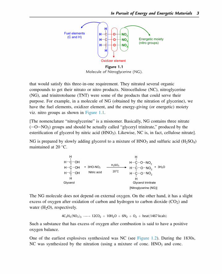
that would satisfy this three-in-one requirement. They nitrated several organic
compounds to get their nitrato or nitro products. Nitrocellulose (NC), nitroglycerine
(NG), and trinitrotoluene (TNT) were some of the products that could serve their
purpose. For example, in a molecule of NG (obtained by the nitration of glycerine), we
have the fuel elements, oxidizer element, and the energy-giving (or energetic) moiety
viz. nitro groups as shown in Figure 1.1.
[The nomenclature “nitroglycerine” is a misnomer. Basically, NG contains three nitrate
(eOeNO2) groups and should be actually called “glyceryl trinitrate,” produced by the
esterification of glycerol by nitric acid (HNO3). Likewise, NC is, in fact, cellulose nitrate].
NG is prepared by slowly adding glycerol to a mixture of HNO3 and sulfuric acid (H2SO4)
maintained at 20 �C.
CC
CH
OHH
HH
OHH
OH
CC
CH
OH
HH
OH
O NO2
NO2
NO2
H2SO4
20°C+ 3HO-NO2 + 3H2O
Nitric acid
Glycerol Glycerol trinitrate
[Nitroglycerine (NG)]
The NG molecule does not depend on external oxygen. On the other hand, it has a slight
excess of oxygen after oxidation of carbon and hydrogen to carbon dioxide (CO2) and
water (H2O), respectively.
4C3H5ðNO3Þ3 ���! 12CO2 þ 10H2O þ 6N2 þ O2 þ heatð1467 kcalsÞ
Such a substance that has excess of oxygen after combustion is said to have a positive
oxygen balance.
One of the earliest explosives synthesized was NC (see Figure 1.2). During the 1830s,
NC was synthesized by the nitration (using a mixture of conc. HNO3 and conc.
CC
CH
OH
HH
OH
O NO2
NO2
NO2Energetic moiety (nitro groups)
Fuel elements (C and H)
Oxidizer element
Figure 1.1Molecule of Nitroglycerine (NG).
In Pursuit of Energy and Energetic Materials 3
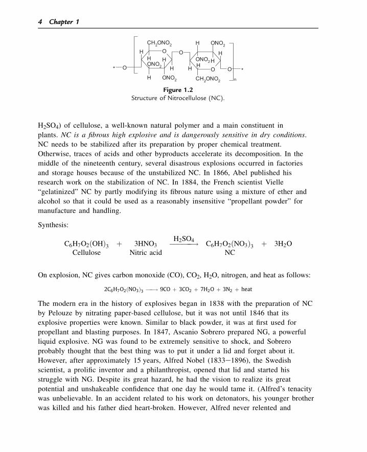
H2SO4) of cellulose, a well-known natural polymer and a main constituent in
plants. NC is a fibrous high explosive and is dangerously sensitive in dry conditions.
NC needs to be stabilized after its preparation by proper chemical treatment.
Otherwise, traces of acids and other byproducts accelerate its decomposition. In the
middle of the nineteenth century, several disastrous explosions occurred in factories
and storage houses because of the unstabilized NC. In 1866, Abel published his
research work on the stabilization of NC. In 1884, the French scientist Vielle
“gelatinized” NC by partly modifying its fibrous nature using a mixture of ether and
alcohol so that it could be used as a reasonably insensitive “propellant powder” for
manufacture and handling.
Synthesis:
C6H7O2ðOHÞ3 þ 3HNO3 ������!H2SO4C6H7O2ðNO3Þ3 þ 3H2O
Cellulose Nitric acid NC
On explosion, NC gives carbon monoxide (CO), CO2, H2O, nitrogen, and heat as follows:
2C6H7O2ðNO3Þ3 ���! 9CO þ 3CO2 þ 7H2O þ 3N2 þ heat
The modern era in the history of explosives began in 1838 with the preparation of NC
by Pelouze by nitrating paper-based cellulose, but it was not until 1846 that its
explosive properties were known. Similar to black powder, it was at first used for
propellant and blasting purposes. In 1847, Ascanio Sobrero prepared NG, a powerful
liquid explosive. NG was found to be extremely sensitive to shock, and Sobrero
probably thought that the best thing was to put it under a lid and forget about it.
However, after approximately 15 years, Alfred Nobel (1833e1896), the Swedish
scientist, a prolific inventor and a philanthropist, opened that lid and started his
struggle with NG. Despite its great hazard, he had the vision to realize its great
potential and unshakeable confidence that one day he would tame it. (Alfred’s tenacity
was unbelievable. In an accident related to his work on detonators, his younger brother
was killed and his father died heart-broken. However, Alfred never relented and
O
H
ONO2
H
CH2ONO2
H
HOOCH2ONO2
HH
H
ONO2
ONO2
HH
ONO2
HO *O*
n
Figure 1.2Structure of Nitrocellulose (NC).
4 Chapter 1
carried on with his research and development in detonators). NG (nitroglycerine) is a
dangerously sensitive material when it undergoes even mild impact. Kieselghur was
found to be the first inert material, which when mixed with NG could desensitize NG,
by taming its sensitivity. Dynamite was the first substance using NG that could be
safely and conveniently handled. After a lapse of approximately 135 years, dynamite is
still used for certain civil applications. A more startling discovery by Nobel followed
when he mixed sensitive NG with sensitive NC and got an insensitive, gelatinized
dough. This gelatinized material was found to be a powerful blaster and accordingly
called “blasting gelatin.” This discovery paved the way for the development of many
blasting explosives (dry NC can absorb up to 11.5 times its weight of NG;
accordingly, blasting gelatine has a composition of 92% NG and 8% NC). In 1888,
Nobel developed the first “smokeless powder” (called ballistite) for military application
in place of gun powder. It was a mixture of NC and NG (called “double-base”) and
substances such as camphor, which acted as plasticizers. Prolific inventions by Nobel
resulted in many patents to the credit of this genius who revolutionized the explosives
industry. He accumulated a huge fortune and it is common knowledge that the
prestigious Nobel Prizes are given as a result of this fortune.
From the middle of nineteenth century, many explosives and energetic ingredients have
been synthesized. Appendix A gives the important milestones in the history of
development of explosives and propellants. During the last 150 years, with great strides
made in the field of chemistry, physics, instrumentation, and computers, we have come
a long way in the field of explosives and propellants. Scientists are constantly on the hunt
for better and better candidate molecules with regard to energy content, rate of release of
energy, density, and other parameters so that they can be used for futuristic explosive
compositions or as propellant ingredients.
The pursuit that started with gunpowder some centuries back is still very much on. The
targets are presently molecules that have a highly strained structure, have maximum
density, and contain energetic groups. One such molecule that has been recently
synthesized is octanitrocubane (Figure 1.3).
NO2
O2 N
O2 N
NO2 NO2
NO2
NO2
O2 N
Figure 1.3Octanitrocubane.
In Pursuit of Energy and Energetic Materials 5
The advancing techniques of modern warfare lead to more and more specialized
requirements for explosives and propellants. We will see in greater detail about such
requirements in subsequent chapters.
1.3 Classification of Explosives
The term “explosives” has been defined in various ways and probably the most accepted
definition is as follows: “An explosive is a chemical or mixture of chemicals which, when
suitably initiated, can react so rapidly and with such liberation of energy that there can be
damage to the surroundings.” The explosives can be classified in two different ways:
1. High explosives or detonating explosives (subdivided into primary explosives and
secondary explosives)
2. Low explosives or deflagrating explosives (propellants)
Propellants that propel a projectile from a pistol, mortar, or gun fall under the category of
low explosives. They deflagrate layer by layer at a predetermined rate evolving a large
amount of high-pressure hot gases that do the trick of propelling the projectile. Rocket
propellants that cause the self-propulsion of a rocket are also referred to as low explosives.
Primary explosives are quite sensitive to initiation by mechanical impact, flame, or spark.
Among high explosives, secondary explosives such as TNT and RDX (research and
development explosive) detonate with violence, causing a high-velocity shock wave and
blast effect. They are fairly insensitive and need to be initiated by primary explosives such
as certain metallic azides. Although they are not as powerful as secondary explosives,
primary explosives have enough power to detonate a secondary explosive on initiation.
The second type under which explosives can be classified is based on their end use viz.
military explosives and civil explosives (sometimes referred to as commercial explosives).
The requirements, properties, and cost are quite varied between these two categories of
explosives. The important requirements of military explosives are presented in the
following subsections.
1.3.1 Maximum Power per Unit Volume
This implies that a given volume of a high explosive (e.g., in a shell or warhead), on
detonation, should produce high-pressure and high-temperature gases in such a way that
they do maximum work (of expansion) per unit time.
1.3.2 High Velocity of Detonation
Velocity of detonation (VOD) is the rate at which the shock wave front travels in the
medium of an explosive. This is a vital parameter for most of the military explosives
6 Chapter 1
because it is directly proportional to the shattering effect of the detonation (e.g., in
a grenade) and the jet velocity in shaped charges. It is measured in units of kilometers per
second or meters per second (e.g., VOD of RDX is 8.850 km/s).
1.3.3 Long-Term Storage Stability
Wars are not an everyday affair. In times of peace, all of the explosives-filled ammunitions
are under storage over long periods of timedsometimes for a few decades. For this
purpose, one cannot choose an explosive that deteriorates in stability within a few years.
Therefore, military explosives should have long-term stability over a wide range of
temperatures (e.g., from �40 �C to þ60 �C).
1.3.4 Insensitivity to Shock and Impact
Explosives should go off when they are supposed to go off (reliability), but they should
not go off when they are not supposed to go off (safety). Hence, this is an important
safety-related requirement for any military explosive at various stages of handling and
transport.
1.3.5 Ability to Withstand Large Accelerations
The high explosives filled in ammunition have to encounter huge accelerations (e.g., in
the bore of a gun accelerations up to 40,000 g may be experienced) or negative
accelerations (e.g., in the penetration by an armor-piercing shell through an armor plate).
It should be ensured that the HE (high explosive) filling should not be initiated by such
acceleration or deceleration.
In sharp contrast to military explosives, civil explosives do not generally require high
VOD or too high of a blast effect. In fact, a high-VOD explosive may prove to be
disastrous in certain civil applications such as coal mining in which the high-velocity
shock waves might result in adiabatic compression and the initiation of the marsh gas
(methane) present in the coal mines. The “power” of the explosives or explosive
compositions can be tailored by adjusting the composition to suit the needs.
Cost is a dominant factor in civil explosives. One cannot afford to produce a costly civil
explosive simply because it will not sell. A coal-mining magnate may simply ask you
“What is the cost of your explosive needed to mine 1 ton of coal in the required range of
lump size?”
Unlike military explosives, the shelf life of civil explosives is not very critical. After all,
they are fast-moving items, and one might talk of shelf life of 6 months or 1 year versus
20 or 25 years for a military explosive.
In Pursuit of Energy and Energetic Materials 7
1.4 Explosives and Molecular Structure
Why are only some compounds explosives whereas many others are not? Only in some
compounds, the molecules are
1. having a huge potential energy packed in them (which is related to their heats of
formation, a topic that will be discussed in the Chapter 2);
2. in a meta-stable state, implying that they need only a small amount of trigger or
activation energy to initiate them for the release of the dormant potential energy in
a very short time.
Because this is basically a molecular phenomenon, a relationship does exist between the
molecular structure and the explosive property.
It was proposed that an explosive molecule has in its structure certain groups that are
responsible for their explosive property (e.g., eONO2, eNO2, N-NO2, eClO4, eN3, etc.).
These were called “explosophores” (similar to “chromophore” groups such as an azo
group that imparts color to a dye). Paul W. Cooper in his book Explosives Engineering
talks about four different substituent groups found in explosives viz.
1. Oxidizer contributor (e.g., eONO2, eNO2, eNF2)
2. Fuel contributor (e.g., alkyl, eNH2, eNH)
3. Combined fuel-oxidizer contributor (eONC: fulminate, eNH-NO2: nitramines)
4. Bond-energy contributor (e.g., eN3: azides), which contributes energy to the detonation
process when their high-energy bonds are broken.
If we take the above combinations, there must theoretically be thousands of explosives
(particularly organic) available to us. However, the actual number of explosives being used
or pursued is severely restricted by several factors, such as thermal stability, sensitivity,
chemical compatibility, toxicity, and explosive output of the finally synthesized explosive
apart from the cost and feasibility of the synthesis.
In terms of molecular structure, the explosives can be classified as shown in Figure 1.4.
1.5 Classification of Propellants
Propellants are defined as low explosives or deflagrating explosives. Such a definition is
rather loose because the roles of a deflagrating explosive and detonating explosive can be
reversed depending on the conditions. A propellant detonates under very high confinement
and a high explosive such as RDX can be made to silently burn as a propellant ingredient.
However, in this book, the term “propellant” will refer to those materials that burn
(without the help of external oxygen) layer by layer at a predetermined or predictable rate
evolving high pressure and hot gases.
8 Chapter 1
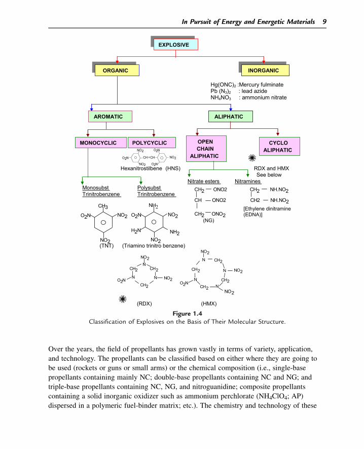
Over the years, the field of propellants has grown vastly in terms of variety, application,
and technology. The propellants can be classified based on either where they are going to
be used (rockets or guns or small arms) or the chemical composition (i.e., single-base
propellants containing mainly NC; double-base propellants containing NC and NG; and
triple-base propellants containing NC, NG, and nitroguanidine; composite propellants
containing a solid inorganic oxidizer such as ammonium perchlorate (NH4ClO4; AP)
dispersed in a polymeric fuel-binder matrix; etc.). The chemistry and technology of these
Hg(ONC)2 :Mercury fulminatePb (N3)2 : lead azideNH4NO3 : ammonium nitrate
Hexanitrostilbene (HNS) RDX and HMX See below
Nitrate esters NitraminesMonosubst PolysubstTrinitrobenzene Trinitrobenzene
(TNT) (Triamino trinitro benzene)
(RDX) (HMX)
ORGANIC INORGANIC
EXPLOSIVE
AROMATIC ALIPHATIC
MONOCYCLIC POLYCYCLIC OPEN CHAIN
ALIPHATIC
CYCLO ALIPHATIC
O2N
NO2
CH =CH
NO2
O2N
O2N
NO2
O2N
CH3NO2
NO2 NO2
NO2
NH2O2N
H2N NH2
NCH2
N
CH2
CH2
N
NO2
O2N NO2
NO2
O2N
NO2
N
CH2
CH2
N
CH2
N
CH2N
NO2
CH2 ONO2 CH2 NH.NO2
CH ONO2 CH2 NH.NO2
CH2 ONO2[Ethylene dinitramine (EDNA)]
(NG)
Figure 1.4Classification of Explosives on the Basis of Their Molecular Structure.
In Pursuit of Energy and Energetic Materials 9
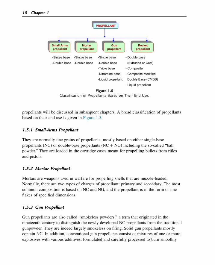
propellants will be discussed in subsequent chapters. A broad classification of propellants
based on their end use is given in Figure 1.5.
1.5.1 Small-Arms Propellant
They are normally fine grains of propellants, mostly based on either single-base
propellants (NC) or double-base propellants (NC þ NG) including the so-called “ball
powder.” They are loaded in the cartridge cases meant for propelling bullets from rifles
and pistols.
1.5.2 Mortar Propellant
Mortars are weapons used in warfare for propelling shells that are muzzle-loaded.
Normally, there are two types of charges of propellant: primary and secondary. The most
common composition is based on NC and NG, and the propellant is in the form of fine
flakes of specified dimensions.
1.5.3 Gun Propellant
Gun propellants are also called “smokeless powders,” a term that originated in the
nineteenth century to distinguish the newly developed NC propellants from the traditional
gunpowder. They are indeed largely smokeless on firing. Solid gun propellants mostly
contain NC. In addition, conventional gun propellants consist of mixtures of one or more
explosives with various additives, formulated and carefully processed to burn smoothly
-Single base
-Double base
-Single base
-Double base
-Single base
-Double base
-Triple base
-Nitramine base
-Liquid propellant
- Double base
(Extruded or Cast)
- Composite
- Composite Modified
Double Base (CMDB)
- Liquid propellant
Mortar propellant
Gun propellant
Rocket propellant
Small Armspropellant
PROPELLANT
Figure 1.5Classification of Propellants Based on Their End Use.
10 Chapter 1
without detonating, under the conditions in which they are normally used. The essential
required properties of gun propellants are as follows:
1. Minimal smoke or flash
2. Less toxic fumes
3. Long shelf life under all environmental conditions
4. Easy and rapid ignition
5. Low sensitivities to all other possible cause of initiation
6. Low flame temperature
1.5.4 Rocket Propellant
Rocket propellants provide a simple and effective way of creating propulsion for flight.
The first true military use was by British troops in the eighteenth century against Indians.
By 1805, Sir William Congreve had devised a system for the British, and these propellants
provided an important military advantage in the following decade. By the start of World
War I, such rockets, all powered by gunpowder, had become obsolete. Since then, the vital
importance of rocket-powered weapons to attack on land, sea, and in the air has
tremendously increased.
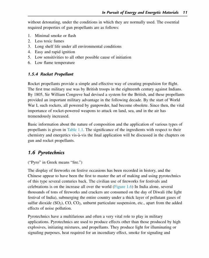
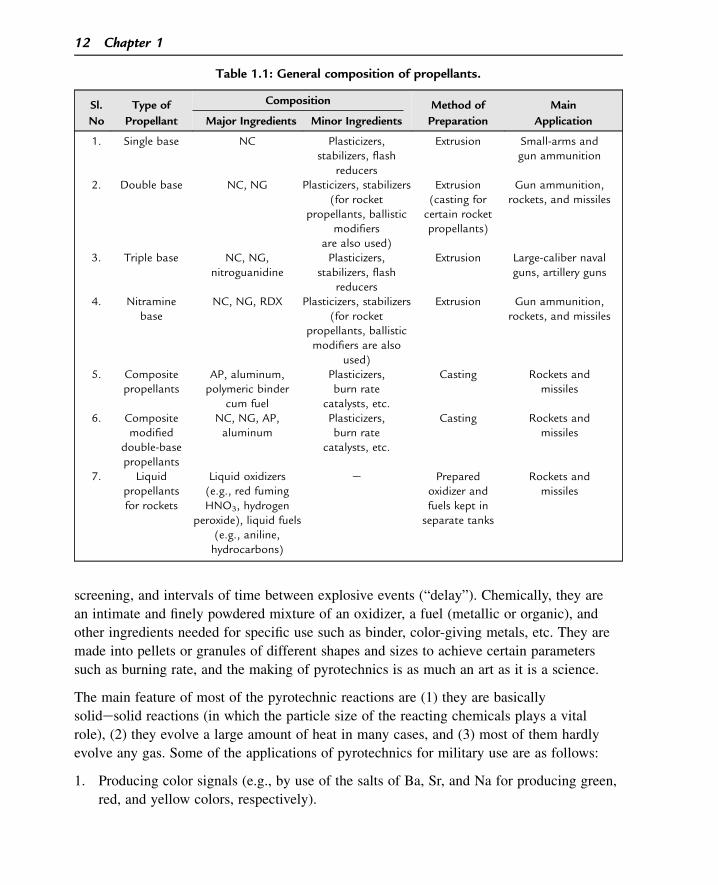
Basic information about the nature of composition and the application of various types of
propellants is given in Table 1.1. The significance of the ingredients with respect to their
chemistry and energetics vis-a-vis the final application will be discussed in the chapters on
gun and rocket propellants.
1.6 Pyrotechnics
(“Pyro” in Greek means “fire.”)
The display of fireworks on festive occasions has been recorded in history, and the
Chinese appear to have been the first to master the art of making and using pyrotechnics
of this type several centuries back. The civilian use of fireworks for festivals and
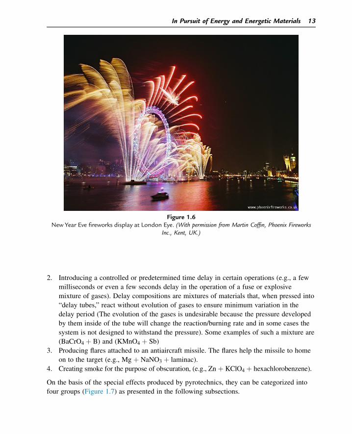
celebrations is on the increase all over the world (Figure 1.6) In India alone, several
thousands of tons of fireworks and crackers are consumed on the day of Diwali (the light
festival of India), submerging the entire country under a thick layer of pollutant gases of
sulfur dioxide (SO2), CO, CO2, unburnt particulate suspension, etc., apart from the added
effects of noise pollution.
Pyrotechnics have a multifarious and often a very vital role to play in military
applications. Pyrotechnics are used to produce effects other than those produced by high
explosives, initiating mixtures, and propellants. They produce light for illuminating or
signaling purposes, heat required for an incendiary effect, smoke for signaling and
In Pursuit of Energy and Energetic Materials 11
screening, and intervals of time between explosive events (“delay”). Chemically, they are
an intimate and finely powdered mixture of an oxidizer, a fuel (metallic or organic), and
other ingredients needed for specific use such as binder, color-giving metals, etc. They are
made into pellets or granules of different shapes and sizes to achieve certain parameters
such as burning rate, and the making of pyrotechnics is as much an art as it is a science.
The main feature of most of the pyrotechnic reactions are (1) they are basically
solidesolid reactions (in which the particle size of the reacting chemicals plays a vital
role), (2) they evolve a large amount of heat in many cases, and (3) most of them hardly
evolve any gas. Some of the applications of pyrotechnics for military use are as follows:
1. Producing color signals (e.g., by use of the salts of Ba, Sr, and Na for producing green,
red, and yellow colors, respectively).
Table 1.1: General composition of propellants.
Sl.
No
Type of
Propellant
Composition Method of
Preparation
Main
ApplicationMajor Ingredients Minor Ingredients
1. Single base NC Plasticizers,stabilizers, flash
reducers
Extrusion Small-arms andgun ammunition
2. Double base NC, NG Plasticizers, stabilizers(for rocket
propellants, ballisticmodifiers
are also used)
Extrusion(casting forcertain rocketpropellants)
Gun ammunition,rockets, and missiles
3. Triple base NC, NG,nitroguanidine
Plasticizers,stabilizers, flash
reducers
Extrusion Large-caliber navalguns, artillery guns
4. Nitraminebase
NC, NG, RDX Plasticizers, stabilizers(for rocket
propellants, ballisticmodifiers are also
used)
Extrusion Gun ammunition,rockets, and missiles
5. Compositepropellants
AP, aluminum,polymeric binder
cum fuel
Plasticizers,burn rate
catalysts, etc.
Casting Rockets andmissiles
6. Compositemodified
double-basepropellants
NC, NG, AP,aluminum
Plasticizers,burn rate
catalysts, etc.
Casting Rockets andmissiles
7. Liquidpropellantsfor rockets
Liquid oxidizers(e.g., red fumingHNO3, hydrogen
peroxide), liquid fuels(e.g., aniline,hydrocarbons)
e Preparedoxidizer andfuels kept inseparate tanks
Rockets andmissiles
12 Chapter 1
2. Introducing a controlled or predetermined time delay in certain operations (e.g., a few
milliseconds or even a few seconds delay in the operation of a fuse or explosive
mixture of gases). Delay compositions are mixtures of materials that, when pressed into
“delay tubes,” react without evolution of gases to ensure minimum variation in the
delay period (The evolution of the gases is undesirable because the pressure developed
by them inside of the tube will change the reaction/burning rate and in some cases the
system is not designed to withstand the pressure). Some examples of such a mixture are
(BaCrO4 þ B) and (KMnO4 þ Sb)
3. Producing flares attached to an antiaircraft missile. The flares help the missile to home
on to the target (e.g., Mg þ NaNO3 þ laminac).
4. Creating smoke for the purpose of obscuration, (e.g., Zn þ KClO4 þ hexachlorobenzene).
On the basis of the special effects produced by pyrotechnics, they can be categorized into
four groups (Figure 1.7) as presented in the following subsections.
Figure 1.6New Year Eve fireworks display at London Eye. (With permission from Martin Coffin, Phoenix Fireworks
Inc., Kent, UK.)
In Pursuit of Energy and Energetic Materials 13
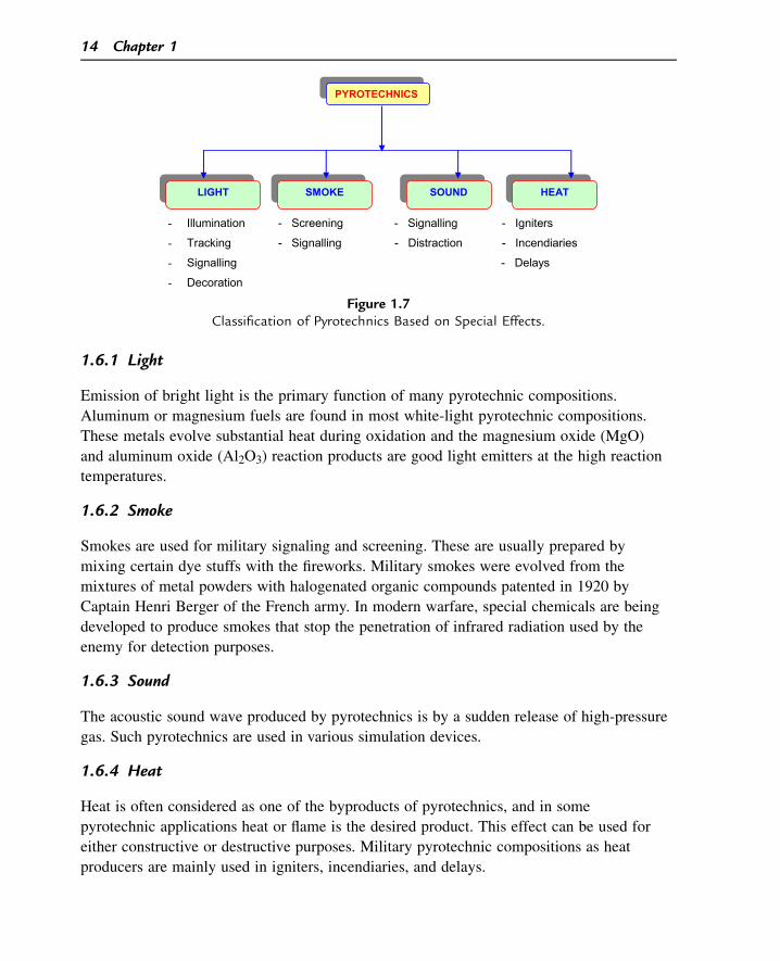
1.6.1 Light
Emission of bright light is the primary function of many pyrotechnic compositions.
Aluminum or magnesium fuels are found in most white-light pyrotechnic compositions.
These metals evolve substantial heat during oxidation and the magnesium oxide (MgO)
and aluminum oxide (Al2O3) reaction products are good light emitters at the high reaction
temperatures.
1.6.2 Smoke
Smokes are used for military signaling and screening. These are usually prepared by
mixing certain dye stuffs with the fireworks. Military smokes were evolved from the
mixtures of metal powders with halogenated organic compounds patented in 1920 by
Captain Henri Berger of the French army. In modern warfare, special chemicals are being
developed to produce smokes that stop the penetration of infrared radiation used by the
enemy for detection purposes.
1.6.3 Sound
The acoustic sound wave produced by pyrotechnics is by a sudden release of high-pressure
gas. Such pyrotechnics are used in various simulation devices.
1.6.4 Heat
Heat is often considered as one of the byproducts of pyrotechnics, and in some
pyrotechnic applications heat or flame is the desired product. This effect can be used for
either constructive or destructive purposes. Military pyrotechnic compositions as heat
producers are mainly used in igniters, incendiaries, and delays.
- Illumination - Screening - Signalling - Igniters
- Tracking - Signalling - Distraction - Incendiaries
- Signalling - Delays
- Decoration
PYROTECHNICS
LIGHT HEATSMOKE SOUND
Figure 1.7Classification of Pyrotechnics Based on Special Effects.
14 Chapter 1
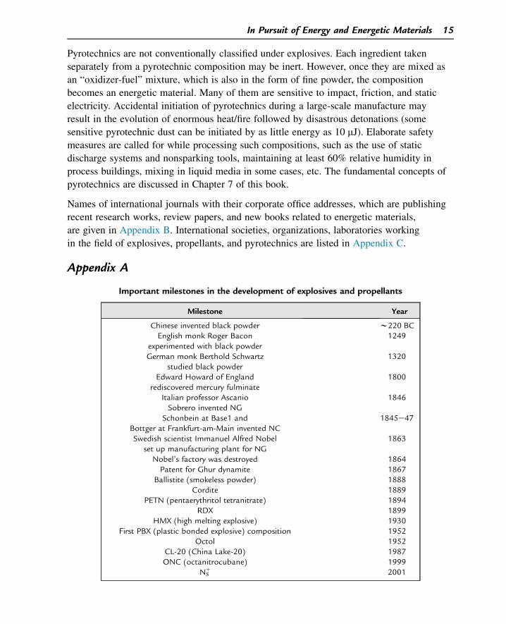
Pyrotechnics are not conventionally classified under explosives. Each ingredient taken
separately from a pyrotechnic composition may be inert. However, once they are mixed as
an “oxidizer-fuel” mixture, which is also in the form of fine powder, the composition
becomes an energetic material. Many of them are sensitive to impact, friction, and static
electricity. Accidental initiation of pyrotechnics during a large-scale manufacture may
result in the evolution of enormous heat/fire followed by disastrous detonations (some
sensitive pyrotechnic dust can be initiated by as little energy as 10 mJ). Elaborate safety
measures are called for while processing such compositions, such as the use of static
discharge systems and nonsparking tools, maintaining at least 60% relative humidity in
process buildings, mixing in liquid media in some cases, etc. The fundamental concepts of
pyrotechnics are discussed in Chapter 7 of this book.
Names of international journals with their corporate office addresses, which are publishing
recent research works, review papers, and new books related to energetic materials,
are given in Appendix B. International societies, organizations, laboratories working
in the field of explosives, propellants, and pyrotechnics are listed in Appendix C.
Appendix A
Important milestones in the development of explosives and propellants
Milestone Year
Chinese invented black powder w220 BCEnglish monk Roger Bacon
experimented with black powder1249
German monk Berthold Schwartzstudied black powder
1320
Edward Howard of Englandrediscovered mercury fulminate
1800
Italian professor AscanioSobrero invented NG
1846
Schonbein at Base1 andBottger at Frankfurt-am-Main invented NC
1845e47
Swedish scientist Immanuel Alfred Nobelset up manufacturing plant for NG
1863
Nobel’s factory was destroyed 1864Patent for Ghur dynamite 1867
Ballistite (smokeless powder) 1888Cordite 1889
PETN (pentaerythritol tetranitrate) 1894RDX 1899
HMX (high melting explosive) 1930First PBX (plastic bonded explosive) composition 1952
Octol 1952CL-20 (China Lake-20) 1987ONC (octanitrocubane) 1999
N5þ 2001
In Pursuit of Energy and Energetic Materials 15
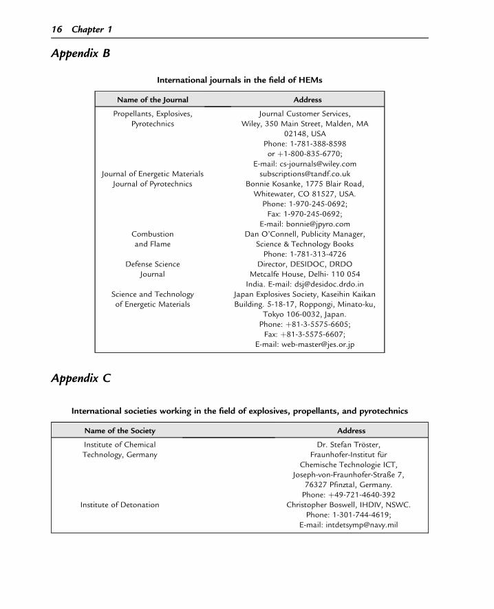
Appendix B
Appendix C
International journals in the field of HEMs
Name of the Journal Address
Propellants, Explosives,Pyrotechnics
Journal Customer Services,Wiley, 350 Main Street, Malden, MA
02148, USAPhone: 1-781-388-8598or þ1-800-835-6770;
E-mail: [email protected] of Energetic Materials [email protected]
Journal of Pyrotechnics Bonnie Kosanke, 1775 Blair Road,Whitewater, CO 81527, USA.
Phone: 1-970-245-0692;Fax: 1-970-245-0692;
E-mail: [email protected] Flame
Dan O’Connell, Publicity Manager,Science & Technology BooksPhone: 1-781-313-4726
Defense ScienceJournal
Director, DESIDOC, DRDOMetcalfe House, Delhi- 110 054India. E-mail: [email protected]
Science and Technologyof Energetic Materials
Japan Explosives Society, Kaseihin KaikanBuilding. 5-18-17, Roppongi, Minato-ku,
Tokyo 106-0032, Japan.Phone: þ81-3-5575-6605;Fax: þ81-3-5575-6607;
E-mail: [email protected]
International societies working in the field of explosives, propellants, and pyrotechnics
Name of the Society Address
Institute of ChemicalTechnology, Germany
Dr. Stefan Troster,Fraunhofer-Institut fur
Chemische Technologie ICT,Joseph-von-Fraunhofer-Straße 7,
76327 Pfinztal, Germany.Phone: þ49-721-4640-392
Institute of Detonation Christopher Boswell, IHDIV, NSWC.Phone: 1-301-744-4619;
E-mail: [email protected]
16 Chapter 1
Suggested Reading
[1] S.M. Kaye (Ed.), Encyclopedia of Explosives and Related Items, vol. 1e10, U. S. Army Armament R&DCommand, N.J, 1983.(NOTE: This is the most exhaustive compilation carried out on explosives and related items. To be usedfor “reference” and not “reading.”)
[2] R. Meyer, J. Kohler, Explosives, VCH Publishers, Germany, 1993 (Encyclopedia e handy for referencing).[3] T. Urbanski, Chemistry and Technology of Explosives, vol. 1e4, Pergamon Press, Oxford, New York,
1983.(Considered to be the Bible of explosives chemists and technologists e a ‘must’ reference book in any lab/institution/factory dealing with high energy materials.)
[4] Service Text Book of Explosives, Min. of Defence, Publication, UK, 1972.[5] B. Morgan, Explosions and Explosives, Macmillan (Quantum Books), London, New York, 1967.[6] A. Bailey, S.G. Murray, Explosives, Propellants and Pyrotechnics, Pergamon Press, Oxford, New York,
1988.[7] T.L. Davis, The Chemistry of Powder and Explosives, Wiley, New York, 1956.
Questions
1. Who were the first to invent gunpowder? And, who was the first scientist to describe
its chemical constituents?
2. What are the roles played by sulfur, KNO3, and charcoal in gunpowder?
3. Write the chemical equation for the explosive reaction of gunpowder?
International societies working in the field of explosives, propellants, and pyrotechnicsdcont’d
Name of the Society Address
American Instituteof Aeronautics andAstronautics (AIAA)
AIAA Headquarters, 1801 Alexander BellDrive, Suite 500, Reston,VA 20191-4344 USA.
Phone: 1-703-264-7500or 1-800-639-AIAA;Fax: 1-703-264-7551
Japan Societyof Energetic Materials
Japan Explosives Society, Ichijoji Building,3F, 2-3-22, Azabudai, Minato-ku,
Tokyo 106-0041, Japan.Phone: þ81-3-5575-6605;Fax: þ81-3-5575-6607;
E-mail: [email protected] Energy Materials
Society of IndiaHigh Energy Materials
Research Laboratory (HEMRL),Sutarwadi, Pune-411021.
Fax: 020-25869697;Website: www.hemsichd.org;
E-mail: [email protected]
In Pursuit of Energy and Energetic Materials 17
4. Write the molecular structure of TNT and indicate the fuel, oxidizer, and energetic
moieties in it.
5. How could Alfred Nobel tame the dangerous NG? What do you think is the mecha-
nism behind it?
6. Define explosives.
7. Classify the following explosives as primary, secondary, or low explosives:
(a) Lead azide, (b) b-HMX, (c) TNT, (d) a rocket propellant, (e) tetrazene,
(f) PETN, (g) RDX, (h) a gun propellant, (I) tetryl, (j) mercury fulminate.
8. Why is a molecular explosive preferred to a mixture that acts as an explosive?
9. What important characteristics should a military explosive satisfy?
10. Why can you not use a military explosive for civilian application (and vice versa)?
11. What are explosophores?
12. How would you classify propellants with respect to (a) application and
(b) composition.
13. What are the different applications of pyrotechnics?
14. How do the following differ from each other? (a) a fuel, (b) a propellant,
(c) a high explosive, and (d) a pyrotechnic.
15. What are the major and minor ingredients of common double- and triple-base
propellants?
16. Name some applications of pyrotechnics in the military.
18 Chapter 1
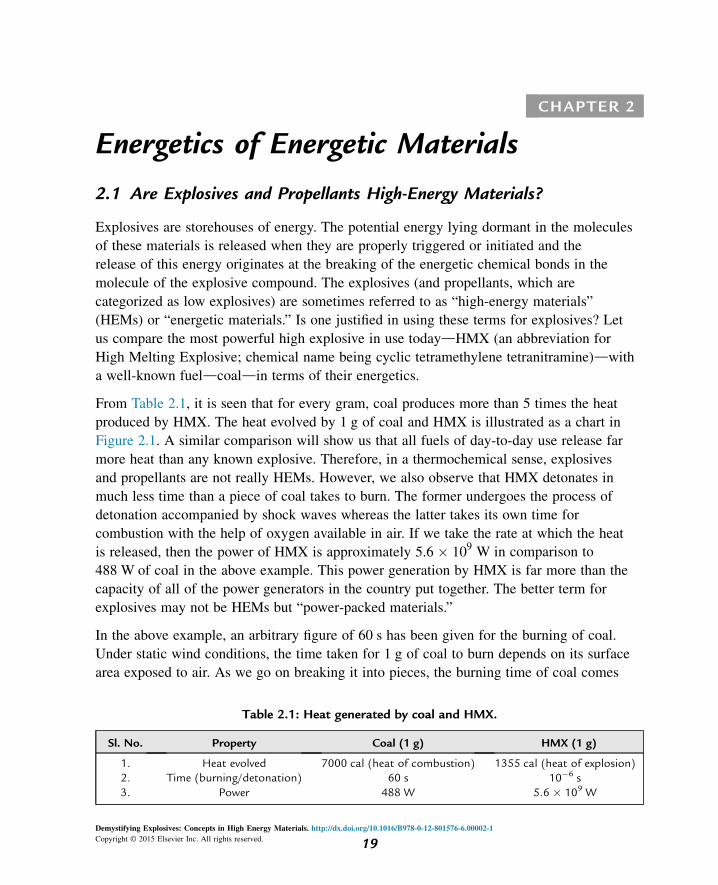
CHAPTER 2
Energetics of Energetic Materials
2.1 Are Explosives and Propellants High-Energy Materials?
Explosives are storehouses of energy. The potential energy lying dormant in the molecules
of these materials is released when they are properly triggered or initiated and the
release of this energy originates at the breaking of the energetic chemical bonds in the
molecule of the explosive compound. The explosives (and propellants, which are
categorized as low explosives) are sometimes referred to as “high-energy materials”
(HEMs) or “energetic materials.” Is one justified in using these terms for explosives? Let
us compare the most powerful high explosive in use todaydHMX (an abbreviation for
High Melting Explosive; chemical name being cyclic tetramethylene tetranitramine)dwith
a well-known fueldcoaldin terms of their energetics.
From Table 2.1, it is seen that for every gram, coal produces more than 5 times the heat
produced by HMX. The heat evolved by 1 g of coal and HMX is illustrated as a chart in
Figure 2.1. A similar comparison will show us that all fuels of day-to-day use release far
more heat than any known explosive. Therefore, in a thermochemical sense, explosives
and propellants are not really HEMs. However, we also observe that HMX detonates in
much less time than a piece of coal takes to burn. The former undergoes the process of
detonation accompanied by shock waves whereas the latter takes its own time for
combustion with the help of oxygen available in air. If we take the rate at which the heat
is released, then the power of HMX is approximately 5.6 � 109 W in comparison to
488 W of coal in the above example. This power generation by HMX is far more than the
capacity of all of the power generators in the country put together. The better term for
explosives may not be HEMs but “power-packed materials.”
In the above example, an arbitrary figure of 60 s has been given for the burning of coal.
Under static wind conditions, the time taken for 1 g of coal to burn depends on its surface
area exposed to air. As we go on breaking it into pieces, the burning time of coal comes
Table 2.1: Heat generated by coal and HMX.
Sl. No. Property Coal (1 g) HMX (1 g)
1. Heat evolved 7000 cal (heat of combustion) 1355 cal (heat of explosion)2. Time (burning/detonation) 60 s 10�6 s3. Power 488 W 5.6 � 109 W
Demystifying Explosives: Concepts in High Energy Materials. http://dx.doi.org/10.1016/B978-0-12-801576-6.00002-1
Copyright © 2015 Elsevier Inc. All rights reserved. 19
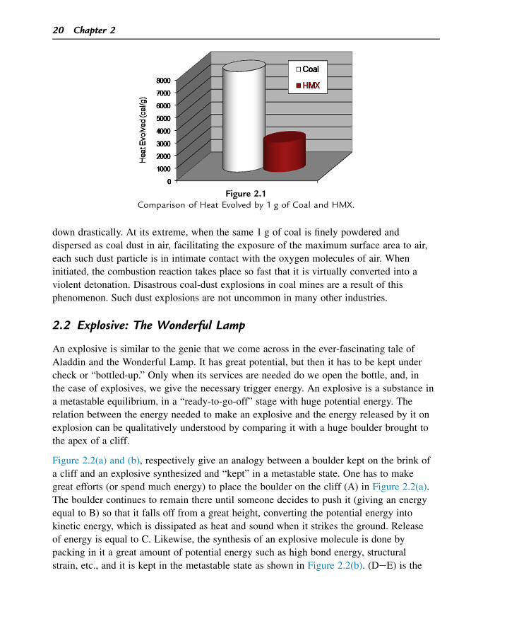
down drastically. At its extreme, when the same 1 g of coal is finely powdered and
dispersed as coal dust in air, facilitating the exposure of the maximum surface area to air,
each such dust particle is in intimate contact with the oxygen molecules of air. When
initiated, the combustion reaction takes place so fast that it is virtually converted into a
violent detonation. Disastrous coal-dust explosions in coal mines are a result of this
phenomenon. Such dust explosions are not uncommon in many other industries.
2.2 Explosive: The Wonderful Lamp
An explosive is similar to the genie that we come across in the ever-fascinating tale of
Aladdin and the Wonderful Lamp. It has great potential, but then it has to be kept under
check or “bottled-up.” Only when its services are needed do we open the bottle, and, in
the case of explosives, we give the necessary trigger energy. An explosive is a substance in
a metastable equilibrium, in a “ready-to-go-off” stage with huge potential energy. The
relation between the energy needed to make an explosive and the energy released by it on
explosion can be qualitatively understood by comparing it with a huge boulder brought to
the apex of a cliff.
Figure 2.2(a) and (b), respectively give an analogy between a boulder kept on the brink of
a cliff and an explosive synthesized and “kept” in a metastable state. One has to make
great efforts (or spend much energy) to place the boulder on the cliff (A) in Figure 2.2(a).
The boulder continues to remain there until someone decides to push it (giving an energy
equal to B) so that it falls off from a great height, converting the potential energy into
kinetic energy, which is dissipated as heat and sound when it strikes the ground. Release
of energy is equal to C. Likewise, the synthesis of an explosive molecule is done by
packing in it a great amount of potential energy such as high bond energy, structural
strain, etc., and it is kept in the metastable state as shown in Figure 2.2(b). (DeE) is the
Figure 2.1Comparison of Heat Evolved by 1 g of Coal and HMX.
20 Chapter 2
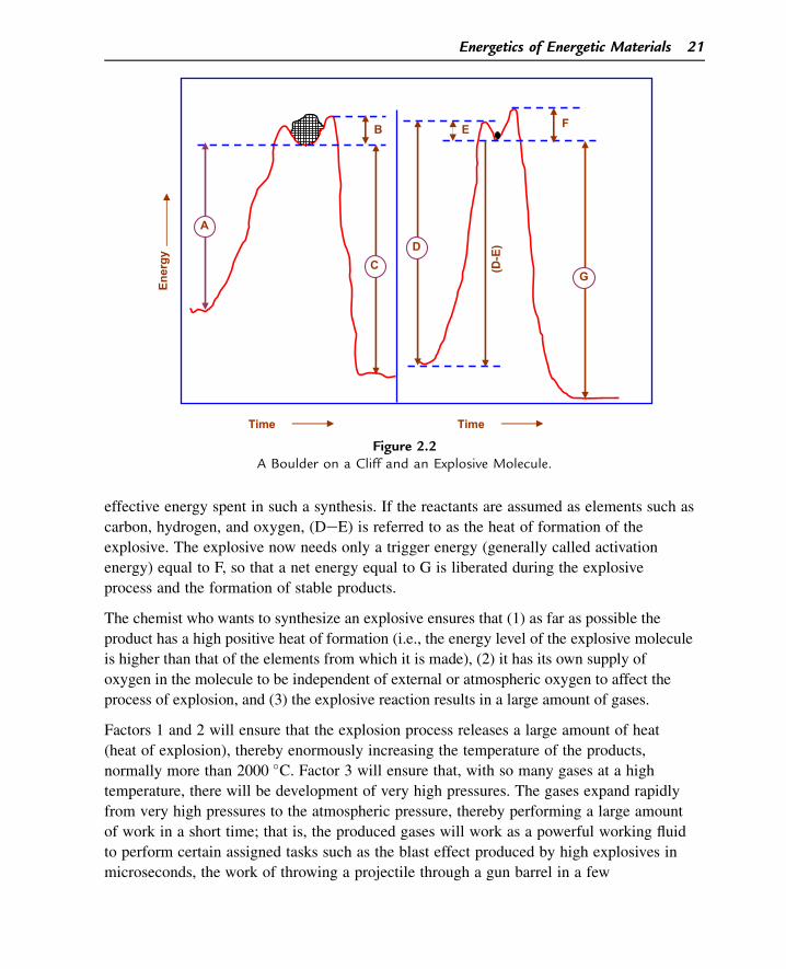
effective energy spent in such a synthesis. If the reactants are assumed as elements such as
carbon, hydrogen, and oxygen, (DeE) is referred to as the heat of formation of the
explosive. The explosive now needs only a trigger energy (generally called activation
energy) equal to F, so that a net energy equal to G is liberated during the explosive
process and the formation of stable products.
The chemist who wants to synthesize an explosive ensures that (1) as far as possible the
product has a high positive heat of formation (i.e., the energy level of the explosive molecule
is higher than that of the elements from which it is made), (2) it has its own supply of
oxygen in the molecule to be independent of external or atmospheric oxygen to affect the
process of explosion, and (3) the explosive reaction results in a large amount of gases.
Factors 1 and 2 will ensure that the explosion process releases a large amount of heat
(heat of explosion), thereby enormously increasing the temperature of the products,
normally more than 2000 �C. Factor 3 will ensure that, with so many gases at a high
temperature, there will be development of very high pressures. The gases expand rapidly
from very high pressures to the atmospheric pressure, thereby performing a large amount
of work in a short time; that is, the produced gases will work as a powerful working fluid
to perform certain assigned tasks such as the blast effect produced by high explosives in
microseconds, the work of throwing a projectile through a gun barrel in a few
A
B E F
(D-E
)
C G
Ener
gy
emiTemiT
D
Figure 2.2A Boulder on a Cliff and an Explosive Molecule.
Energetics of Energetic Materials 21
milliseconds, or the self-propulsion by a rocket in a time period varying from a few
seconds to even a few minutes.
Is an oxidation reaction always necessary in a chemical explosion? Although most of
the chemical explosions involve fast oxidation of fuel elements, it need not be so in
some cases. For example, lead azide (Pb(N3)2), a well-known primary explosive, does
not contain any oxygen atoms in its molecule. However, it has a positive heat of
formation. The azide (eNeN^N) groups attached to the lead atom have weak
linkages and are themselves at a higher energy level. Only a small trigger energy is
necessary to rupture these linkages to produce more stable products with the evolution
of energy.
Pb
�
� Nð�Þ
� Nþð ÞhN
�
2
/Pbþ 3N2 þ 110:8 kcal
2.3 Thermochemistry and Explosive Energy
Chemical reactions are accompanied by energy changes, mainly in the form of heat.
The branch of science that deals with the heat changes during chemical reactions is
called “thermochemistry.” It is essential to remember certain basic concepts in
thermochemistry to obtain better insight into the heat transactions during the formation
and explosion of explosives. The concepts about the three important
parametersdinternal energy (E), heat content or enthalpy (H), and work (W)dshould
also be clear. The internal energy of a substance is the total quantity of energy it
possesses by virtue of its kinetic portion of energy (due to translational, vibrational,
and rotational motions associated with the molecules) and the potential portion of
energy (due to various interatomic, intermolecular, and submolecular forces of
attraction and repulsion). In a chemical reaction in which certain bonds of the reactant
molecules are broken and certain bonds of the product molecules are formed, it is
mostly the kinetic portion of the internal energy that undergoes a change and may be
positive or negative. E is a measure of the absolute temperature of the given substance.
When the temperature increases, all of these kinetic aspects of energy obviously
increase in the molecule.
Heat content, or enthalpy (H), which is defined as H ¼ E þ PV, where P and V are
pressure and volume, respectively, comes in picture when the system undergoes a change
in its E and, at the same time, a certain amount of work is also performed. The work, W,
is taken as W ¼ P(DV), where DV is the change in volume due to the work of expansion.
The absolute values of E and H have no significance. We are interested only in the
changes in the values of E and H (i.e., DE and DH, respectively) of a system when
changes such as a chemical reaction take place.
22 Chapter 2
2.3.1 Heat of Reaction
The net heat absorbed or evolved during a chemical reaction is known as the heat of reaction
(DHr). The reaction involves the expenditure of heat energy to break certain bonds in reactant
molecules and the evolution of heat energy when certain bonds are made in the product
molecules. If the expenditure is more than the evolution, then it is an endothermic reaction
and the converse is true for an exothermic reaction. In an endothermic reaction, DH of the
products is more than that of the reactants and the converse is true for an exothermic reaction.
2.3.1.1 An Endothermic Reaction (Net Heat Absorption)
Heat content
(arbitrary values)
A þ B / C þ D d Heat
80 100 120 100 40
cal cal cal cal cal
DH ¼ HðproductsÞ � HðreactantsÞ¼ ð120þ 100Þ � ð100þ 80Þ ¼ 40 cal; DH ¼ þ40 cal
(2.1)
In its general form, an endothermic reaction can be represented as
Reactants þ ðEnergy absorbed by reactantsÞ / Products
2.3.1.2 An Exothermic Reaction (Net Heat Evolution)
P100 cal
þ Q150 cal
/ R50 cal
þ S75 cal
þ Heat125 cal
DH ¼ HðproductsÞ � HðreactantsÞ¼ ð50þ 75Þ � ð100þ 150Þ ¼ �125 cal DH ¼ �125 cal
In its general form, an exothermic reaction can be represented as
Reactants / Products þ Energy released
It should be remembered that DH is negative for exothermic reactions and positive for
endothermic reactions. All explosive chemical reactions are exothermic, and the DH
values of these reactions are negative.
All heats of reactions are compared at a standard state, which is normally defined as 25 �C(298 K) and 1 atm pressure.
2.3.2 Heat of Formation
The heat of formation (DHf) of a compound is defined as “the heat evolved or absorbed
when 1 mole of the compound is formed from its elements in the standard state.”
Energetics of Energetic Materials 23
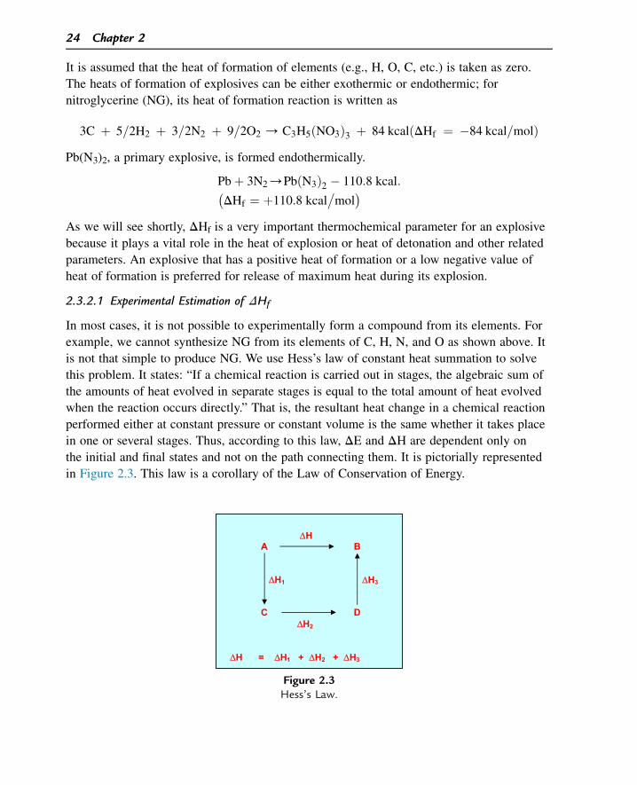
It is assumed that the heat of formation of elements (e.g., H, O, C, etc.) is taken as zero.
The heats of formation of explosives can be either exothermic or endothermic; for
nitroglycerine (NG), its heat of formation reaction is written as
3C þ 5=2H2 þ 3=2N2 þ 9=2O2 / C3H5ðNO3Þ3 þ 84 kcalðDHf ¼ �84 kcal=molÞPb(N3)2, a primary explosive, is formed endothermically.
Pbþ 3N2/PbðN3Þ2 � 110:8 kcal:�
DHf ¼ þ110:8 kcal�
mol�
As we will see shortly, DHf is a very important thermochemical parameter for an explosive
because it plays a vital role in the heat of explosion or heat of detonation and other related
parameters. An explosive that has a positive heat of formation or a low negative value of
heat of formation is preferred for release of maximum heat during its explosion.
2.3.2.1 Experimental Estimation of DHf
In most cases, it is not possible to experimentally form a compound from its elements. For
example, we cannot synthesize NG from its elements of C, H, N, and O as shown above. It
is not that simple to produce NG. We use Hess’s law of constant heat summation to solve
this problem. It states: “If a chemical reaction is carried out in stages, the algebraic sum of
the amounts of heat evolved in separate stages is equal to the total amount of heat evolved
when the reaction occurs directly.” That is, the resultant heat change in a chemical reaction
performed either at constant pressure or constant volume is the same whether it takes place
in one or several stages. Thus, according to this law, DE and DH are dependent only on
the initial and final states and not on the path connecting them. It is pictorially represented
in Figure 2.3. This law is a corollary of the Law of Conservation of Energy.
ΔHA B
ΔH1 ΔH3
C D ΔH2
ΔH = ΔH1 + ΔH2 + ΔH3
Figure 2.3Hess’s Law.
24 Chapter 2
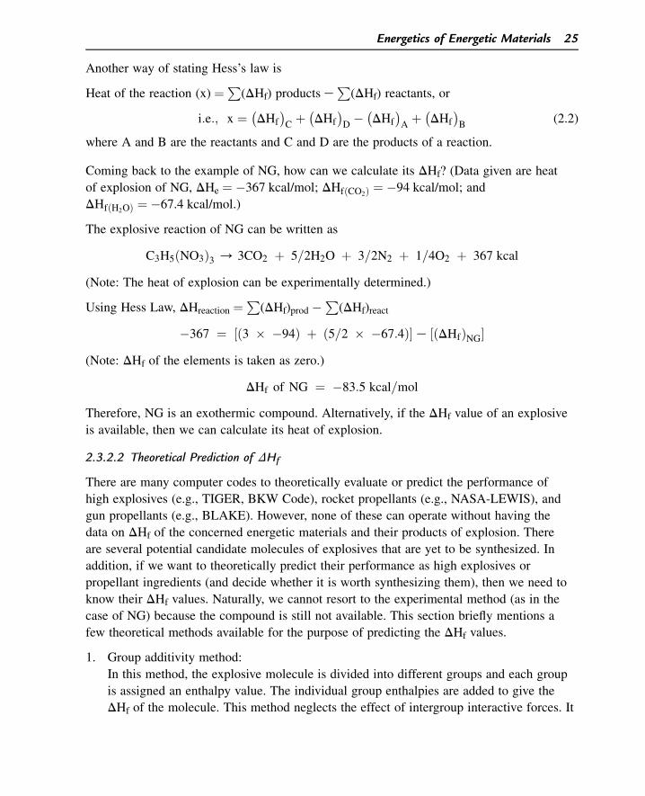
Another way of stating Hess’s law is
Heat of the reaction (x) ¼P
(DHf) products eP
(DHf) reactants, or
i:e:; x ¼ �
DHf
�
Cþ �
DHf
�
D� �
DHf
�
Aþ �
DHf
�
B(2.2)
where A and B are the reactants and C and D are the products of a reaction.
Coming back to the example of NG, how can we calculate its DHf? (Data given are heat
of explosion of NG, DHe ¼ �367 kcal/mol; DHfðCO2Þ ¼ �94 kcal/mol; and
DHfðH2OÞ ¼ �67.4 kcal/mol.)
The explosive reaction of NG can be written as
C3H5ðNO3Þ3 / 3CO2 þ 5=2H2O þ 3=2N2 þ 1=4O2 þ 367 kcal
(Note: The heat of explosion can be experimentally determined.)
Using Hess Law, DHreaction ¼P
(DHf)prod �P
(DHf)react
�367 ¼ ½ð3 � �94Þ þ ð5=2 � �67:4Þ� e ½ðDHfÞNG�(Note: DHf of the elements is taken as zero.)
DHf of NG ¼ �83:5 kcal=mol
Therefore, NG is an exothermic compound. Alternatively, if the DHf value of an explosive
is available, then we can calculate its heat of explosion.
2.3.2.2 Theoretical Prediction of DHf
There are many computer codes to theoretically evaluate or predict the performance of
high explosives (e.g., TIGER, BKW Code), rocket propellants (e.g., NASA-LEWIS), and
gun propellants (e.g., BLAKE). However, none of these can operate without having the
data on DHf of the concerned energetic materials and their products of explosion. There
are several potential candidate molecules of explosives that are yet to be synthesized. In
addition, if we want to theoretically predict their performance as high explosives or
propellant ingredients (and decide whether it is worth synthesizing them), then we need to
know their DHf values. Naturally, we cannot resort to the experimental method (as in the
case of NG) because the compound is still not available. This section briefly mentions a
few theoretical methods available for the purpose of predicting the DHf values.
1. Group additivity method:
In this method, the explosive molecule is divided into different groups and each group
is assigned an enthalpy value. The individual group enthalpies are added to give the
DHf of the molecule. This method neglects the effect of intergroup interactive forces. It
Energetics of Energetic Materials 25
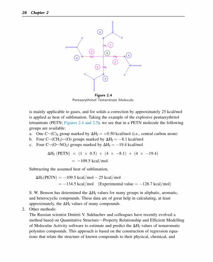
is mainly applicable to gases, and for solids a correction by approximately 25 kcal/mol
is applied as heat of sublimation. Taking the example of the explosive pentaerythritol
tetranitrate (PETN; Figures 2.4 and 2.5), we see that in a PETN molecule the following
groups are available:
a. One Ce(C)4 group marked by DHf ¼ þ0.50 kcal/mol (i.e., central carbon atom)
b. Four Ce(CH2)e(O) groups marked by DHf ¼ �8.1 kcal/mol
c. Four Ce(OeNO2) groups marked by DHf ¼ �19.4 kcal/mol
DHf ðPETNÞ ¼ ð1 � 0:5Þ þ ð4 � e8:1Þ þ ð4 � �19:4Þ¼ e109:5 kcal=mol
Subtracting the assumed heat of sublimation,
DHfðPETNÞ ¼ �109:5 kcal�
mol� 25 kcal�
mol
¼ �134:5 kcal�
mol ðExperimental value ¼ �128:7 kcal=molÞS. W. Benson has determined the DHf values for many groups in aliphatic, aromatic,
and heterocyclic compounds. These data are of great help in calculating, at least
approximately, the DHf values of many compounds.
2. Other methods:
The Russian scientist Dmitrii V. Sukhachev and colleagues have recently evolved a
method based on Quantitative StructuredProperty Relationship and Efficient Modelling
of Molecular Activity software to estimate and predict the DHf values of nonaromatic
polynitro compounds. This approach is based on the construction of regression equa-
tions that relate the structure of known compounds to their physical, chemical, and
C CH2
CH2
CH2
H2C O
O
O
O
N+
O
O
N+
O
O
N+
O
O
N+
O
O
x
y
z
z
z z
y
y
y
Figure 2.4Pentaerythritol Tetranitrate Molecule.
26 Chapter 2
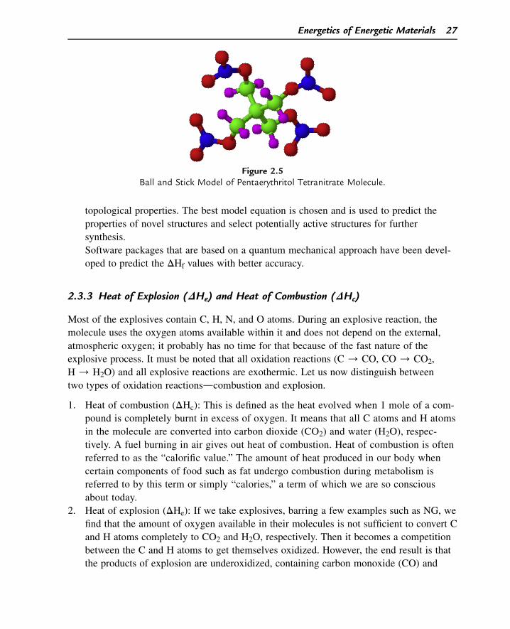
topological properties. The best model equation is chosen and is used to predict the
properties of novel structures and select potentially active structures for further
synthesis.
Software packages that are based on a quantum mechanical approach have been devel-
oped to predict the DHf values with better accuracy.
2.3.3 Heat of Explosion (DHe) and Heat of Combustion (DHc)
Most of the explosives contain C, H, N, and O atoms. During an explosive reaction, the
molecule uses the oxygen atoms available within it and does not depend on the external,
atmospheric oxygen; it probably has no time for that because of the fast nature of the
explosive process. It must be noted that all oxidation reactions (C / CO, CO/ CO2,
H/ H2O) and all explosive reactions are exothermic. Let us now distinguish between
two types of oxidation reactionsdcombustion and explosion.
1. Heat of combustion (DHc): This is defined as the heat evolved when 1 mole of a com-
pound is completely burnt in excess of oxygen. It means that all C atoms and H atoms
in the molecule are converted into carbon dioxide (CO2) and water (H2O), respec-
tively. A fuel burning in air gives out heat of combustion. Heat of combustion is often
referred to as the “calorific value.” The amount of heat produced in our body when
certain components of food such as fat undergo combustion during metabolism is
referred to by this term or simply “calories,” a term of which we are so conscious
about today.
2. Heat of explosion (DHe): If we take explosives, barring a few examples such as NG, we
find that the amount of oxygen available in their molecules is not sufficient to convert C
and H atoms completely to CO2 and H2O, respectively. Then it becomes a competition
between the C and H atoms to get themselves oxidized. However, the end result is that
the products of explosion are underoxidized, containing carbon monoxide (CO) and
Figure 2.5Ball and Stick Model of Pentaerythritol Tetranitrate Molecule.
Energetics of Energetic Materials 27
sometimes H2 and C also. It is evident that the heat of explosion is always less than the
heat of combustion. The underoxidized products of explosion are themselves fuels, and,
in cases of explosion, one finds the secondary fire balls formed due to the further oxida-
tion of these underoxidized products by atmospheric oxygen.
Conventionally, the term heat of explosion is applied to propellants (which are deflagrating
“explosives”) and heat of detonation is used for high explosives. Dunkel defines the heat
of detonation as the heat evolved when an explosive detonates and the products are still at
the ChapmaneJouguet condition (see Chapter 3), in which the gases are at approximately
5000 K and 105 atm in the detonation zone. The composition of the products at the
detonation zone is slightly different from what we may find in a calorimeter; therefore, the
heat of detonation as defined by Dunkel will be slightly different from the heat of
explosion. For all practical purposes, we can take that the heat of detonation is almost
synonymous with the heat of explosion. We will use the term heat of explosion for all
purposes of calculation. Heat of explosion (DHe) is also referred to as the calorimetric
value (shortly “cal.val”). The explosives and propellants depend only on the oxygen
available in their molecules; therefore, they can function even in vacuum. Moreover, the
explosive reactions are too fast to rope in the atmospheric oxygen even if it is available. In
view of this, cal.val (DHe) plays a very important role in the field of explosives and we
rarely talk about calorific value (DHc).
2.3.3.1 Need to Standardize Calorimetric Value
DHe and DHc are experimentally determined using a bomb calorimeter, the experimental
details of which can be had from any standard book on explosives and propellants. In the
case of determination of cal.val, a fixed weight of the explosive (or propellant), usually
approximately 2.5 g, is ignited and exploded after purging the bomb calorimeter with
nitrogen or helium to ensure that no oxygen due to residual air is present at the time of
explosion. The heat evolved is calculated by measuring the increase in temperature of
water in the calorimeter. The cal.val obtained is for the reaction in which water is obtained
in the liquid form. In the case of DHc (calorific value) determination, to ensure complete
combustion, the calorimeter is flushed with an excess of oxygen before the ignition of the
explosive.
For a given explosive compound, DHc is a standard value whereas DHe is not. There is a
need to standardize the conditions under which DHe is to be measured. Let us assume that
in the first experiment we take 2.5 g of an explosive and perform its DHe determination in
a bomb calorimeter, the volume of which is 700 cc (i.e., loading density of the
explosive ¼ 2.5/700 g/cc) and let the cal.val obtained be Q1 cal/g. If the experiment is
repeated with, say, 5 g of the same explosive in the same calorimeter (loading
density ¼ 5/700 g/cc, i.e., twice as in the case of first experiment), then the cal.val
obtained will be different, say Q2 cal/g. In the second experiment, after the explosion, the
28 Chapter 2
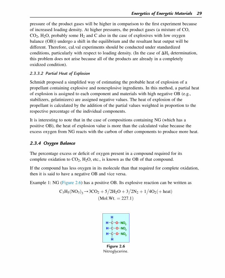
pressure of the product gases will be higher in comparison to the first experiment because
of increased loading density. At higher pressures, the product gases (a mixture of CO,
CO2, H2O, probably some H2 and C also in the case of explosives with low oxygen
balance (OB)) undergo a shift in the equilibrium and the resultant heat output will be
different. Therefore, cal.val experiments should be conducted under standardized
conditions, particularly with respect to loading density. (In the case of DHc determination,
this problem does not arise because all of the products are already in a completely
oxidized condition).
2.3.3.2 Partial Heat of Explosion
Schmidt proposed a simplified way of estimating the probable heat of explosion of a
propellant containing explosive and nonexplosive ingredients. In this method, a partial heat
of explosion is assigned to each component and materials with high negative OB (e.g.,
stabilizers, gelatinizers) are assigned negative values. The heat of explosion of the
propellant is calculated by the addition of the partial values weighted in proportion to the
respective percentage of the individual components.
It is interesting to note that in the case of compositions containing NG (which has a
positive OB), the heat of explosion value is more than the calculated value because the
excess oxygen from NG reacts with the carbon of other components to produce more heat.
2.3.4 Oxygen Balance
The percentage excess or deficit of oxygen present in a compound required for its
complete oxidation to CO2, H2O, etc., is known as the OB of that compound.
If the compound has less oxygen in its molecule than that required for complete oxidation,
then it is said to have a negative OB and vice versa.
Example 1: NG (Figure 2.6) has a positive OB. Its explosive reaction can be written as
C3H5ðNO3Þ3/3CO2 þ 5�
2H2Oþ 3�
2N2 þ 1�
4O2ðþ heatÞðMol:Wt: ¼ 227:1Þ
CC
CH
OH
HH
OH
O NO2
NO2
NO2
Figure 2.6Nitroglycerine.
Energetics of Energetic Materials 29
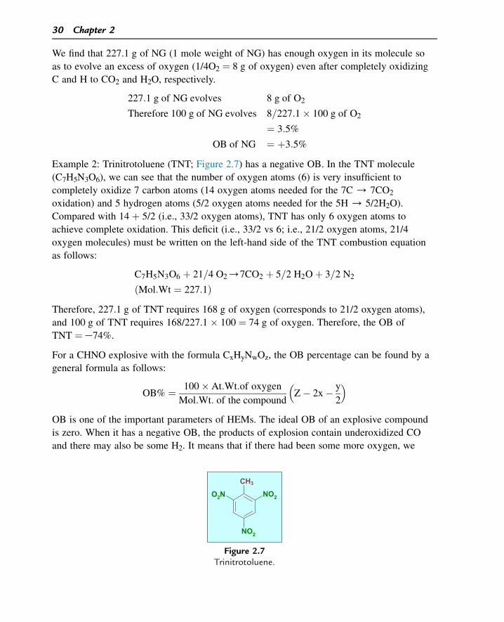
We find that 227.1 g of NG (1 mole weight of NG) has enough oxygen in its molecule so
as to evolve an excess of oxygen (1/4O2 ¼ 8 g of oxygen) even after completely oxidizing
C and H to CO2 and H2O, respectively.
227:1 g of NG evolves 8 g of O2
Therefore 100 g of NG evolves 8=227:1� 100 g of O2
¼ 3:5%
OB of NG ¼ þ3:5%
Example 2: Trinitrotoluene (TNT; Figure 2.7) has a negative OB. In the TNT molecule
(C7H5N3O6), we can see that the number of oxygen atoms (6) is very insufficient to
completely oxidize 7 carbon atoms (14 oxygen atoms needed for the 7C/ 7CO2
oxidation) and 5 hydrogen atoms (5/2 oxygen atoms needed for the 5H / 5/2H2O).
Compared with 14 þ 5/2 (i.e., 33/2 oxygen atoms), TNT has only 6 oxygen atoms to
achieve complete oxidation. This deficit (i.e., 33/2 vs 6; i.e., 21/2 oxygen atoms, 21/4
oxygen molecules) must be written on the left-hand side of the TNT combustion equation
as follows:
C7H5N3O6 þ 21=4 O2/7CO2 þ 5=2 H2Oþ 3=2 N2
ðMol:Wt ¼ 227:1ÞTherefore, 227.1 g of TNT requires 168 g of oxygen (corresponds to 21/2 oxygen atoms),
and 100 g of TNT requires 168/227.1 � 100 ¼ 74 g of oxygen. Therefore, the OB of
TNT ¼ e74%.
For a CHNO explosive with the formula CxHyNwOz, the OB percentage can be found by a
general formula as follows:
OB% ¼ 100� At:Wt:of oxygen
Mol:Wt: of the compound
�
Z� 2x� y
2
�
OB is one of the important parameters of HEMs. The ideal OB of an explosive compound
is zero. When it has a negative OB, the products of explosion contain underoxidized CO
and there may also be some H2. It means that if there had been some more oxygen, we
CH3
NO2O2N
NO2
Figure 2.7Trinitrotoluene.
30 Chapter 2
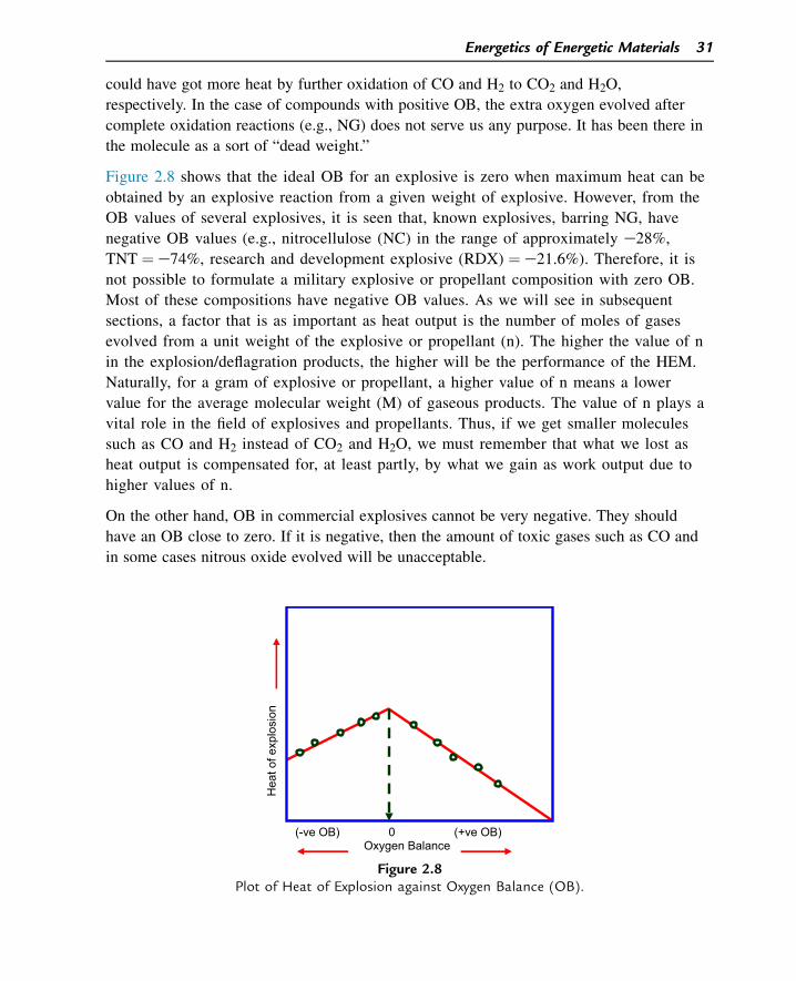
could have got more heat by further oxidation of CO and H2 to CO2 and H2O,
respectively. In the case of compounds with positive OB, the extra oxygen evolved after
complete oxidation reactions (e.g., NG) does not serve us any purpose. It has been there in
the molecule as a sort of “dead weight.”
Figure 2.8 shows that the ideal OB for an explosive is zero when maximum heat can be
obtained by an explosive reaction from a given weight of explosive. However, from the
OB values of several explosives, it is seen that, known explosives, barring NG, have
negative OB values (e.g., nitrocellulose (NC) in the range of approximately e28%,
TNT ¼ e74%, research and development explosive (RDX) ¼ e21.6%). Therefore, it is
not possible to formulate a military explosive or propellant composition with zero OB.
Most of these compositions have negative OB values. As we will see in subsequent
sections, a factor that is as important as heat output is the number of moles of gases
evolved from a unit weight of the explosive or propellant (n). The higher the value of n
in the explosion/deflagration products, the higher will be the performance of the HEM.
Naturally, for a gram of explosive or propellant, a higher value of n means a lower
value for the average molecular weight (M) of gaseous products. The value of n plays a
vital role in the field of explosives and propellants. Thus, if we get smaller molecules
such as CO and H2 instead of CO2 and H2O, we must remember that what we lost as
heat output is compensated for, at least partly, by what we gain as work output due to
higher values of n.
On the other hand, OB in commercial explosives cannot be very negative. They should
have an OB close to zero. If it is negative, then the amount of toxic gases such as CO and
in some cases nitrous oxide evolved will be unacceptable.
(-ve OB) 0 (+ve OB) Oxygen Balance
Hea
t of e
xplo
sion
Figure 2.8Plot of Heat of Explosion against Oxygen Balance (OB).
Energetics of Energetic Materials 31
Worked Example 2.1
Calculate the following parameters for RDX: (1) OB, (2) heat of explosion, and (3) heat of
combustion.
(Given: heats of formation of RDX, CO, CO2, and H2O(l) are þ16.09, e26.7, e94.05,
and �67.42 kcal/mol, respectively).
1. The molecular formula of RDX is C3H6N6O6, which corresponds to a molecular weight
of 222.
It needs three extra oxygen atoms to completely oxidize C and H to CO2 and H2O,
respectively. The combustion equation is written as
C3H6N6O6 þ 3=2O2 / 3CO2 þ 3H2O þ 3N2 ðþDHcÞ
222 g of RDX requires 48 g of oxygen.
Therefore, 100 g of RDX requires 48/222 � 100 g oxygen ¼ 21.6%.
Therefore, the OB of RDX ¼ e21.6%.
2. Heat of combustion (DHc)
From the above equation, we can write
DHc ¼ S�
DHf
�
products� S�
DHf
�
reactants
DHc ¼ ½ð3��94:05Þ þ ð3��67:4Þ� � ð16:09Þ
¼ �500:5 kcal=mole ¼ �500;500 cal=g
222¼ �2255 cal=g
3. Heat of explosion (DHe; in which no external oxygen participates in the reaction)
The explosion reaction of RDX can be written as
C3H6N6O6 / 3CO þ 3H2O þ 3N2 ðþDHeÞ
DHe ¼ S�
DHf
�
products� S�
DHf
�
reactants
¼ ½ð3��26:71Þ þ ð3��67:4Þ� � ð16:09Þ
¼ �298:4 kcal=mole ¼ �298;400
222cal=g
¼ �1344 cal=g
Compared with DHe, DHc is more by 68%.
32 Chapter 2
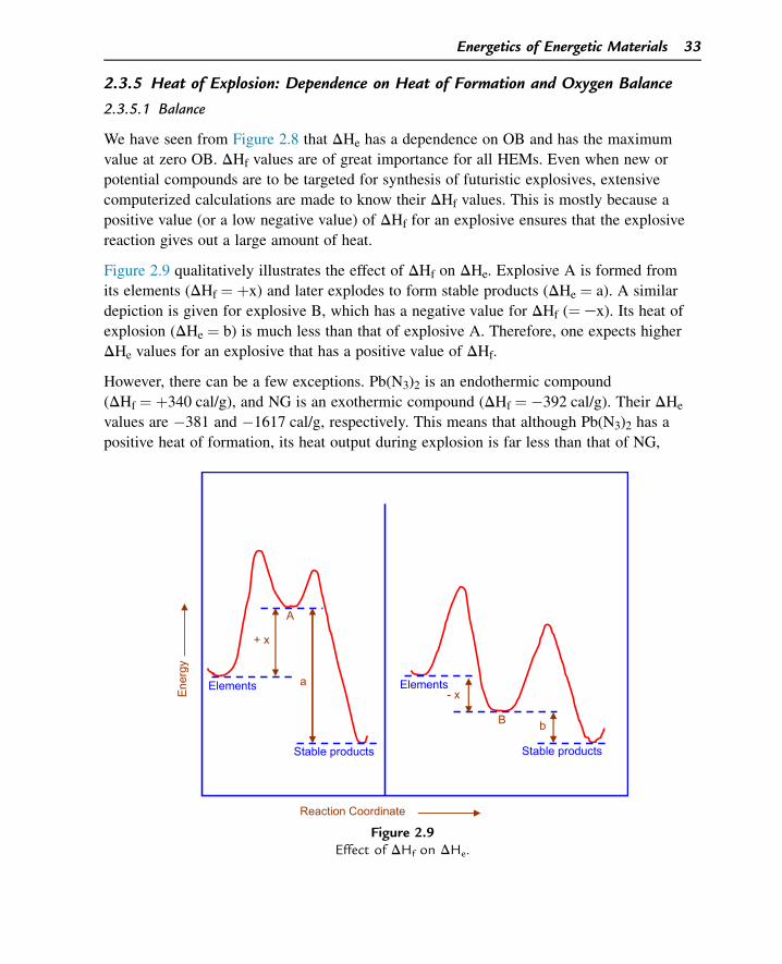
2.3.5 Heat of Explosion: Dependence on Heat of Formation and Oxygen Balance
2.3.5.1 Balance
We have seen from Figure 2.8 that DHe has a dependence on OB and has the maximum
value at zero OB. DHf values are of great importance for all HEMs. Even when new or
potential compounds are to be targeted for synthesis of futuristic explosives, extensive
computerized calculations are made to know their DHf values. This is mostly because a
positive value (or a low negative value) of DHf for an explosive ensures that the explosive
reaction gives out a large amount of heat.
Figure 2.9 qualitatively illustrates the effect of DHf on DHe. Explosive A is formed from
its elements (DHf ¼ þx) and later explodes to form stable products (DHe ¼ a). A similar
depiction is given for explosive B, which has a negative value for DHf (¼ ex). Its heat of
explosion (DHe ¼ b) is much less than that of explosive A. Therefore, one expects higher
DHe values for an explosive that has a positive value of DHf.
However, there can be a few exceptions. Pb(N3)2 is an endothermic compound
(DHf ¼ þ340 cal/g), and NG is an exothermic compound (DHf ¼ �392 cal/g). Their DHe
values are �381 and �1617 cal/g, respectively. This means that although Pb(N3)2 has a
positive heat of formation, its heat output during explosion is far less than that of NG,
Stable products Stable products
Elements Elements
+ x
- x
A
B
a
b
Ene
rgy
Reaction Coordinate
Figure 2.9Effect of DHf on DHe.
Energetics of Energetic Materials 33
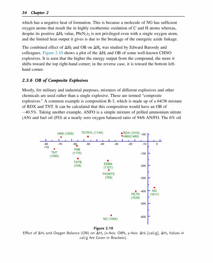
which has a negative heat of formation. This is because a molecule of NG has sufficient
oxygen atoms that result the in highly exothermic oxidation of C and H atoms whereas,
despite its positive DHf value, Pb(N3)2 is not privileged even with a single oxygen atom,
and the limited heat output it gives is due to the breakage of the energetic azide linkage.
The combined effect of DHf and OB on DHe was studied by Edward Baroody and
colleagues. Figure 2.10 shows a plot of the DHf and OB of some well-known CHNO
explosives. It is seen that the higher the energy output from the compound, the more it
shifts toward the top right-hand corner; in the reverse case, it is toward the bottom left-
hand corner.
2.3.6 OB of Composite Explosives
Mostly, for military and industrial purposes, mixtures of different explosives and other
chemicals are used rather than a single explosive. These are termed “composite
explosives.” A common example is composition B-3, which is made up of a 64/36 mixture
of RDX and TNT. It can be calculated that this composition would have an OB of
�40.5%. Taking another example, ANFO is a simple mixture of prilled ammonium nitrate
(AN) and fuel oil (FO) at a nearly zero oxygen balanced ratio of 94/6 AN/FO. The 6% oil
-80 -70 -60 -50 -40 -30 -20 -10 0 +10
+50
-100
-200
-300
-400
-500
-600
RDX (1510) HMX(1480)
PETN (1539)
NC (1064)
NG (1617)
TATB (744)
PICRITE (769)
EDBA (1157)
TNB (1170)TNT
(1090)
HNS (1005) TETRYL (1140)
Figure 2.10Effect of DHf and Oxygen Balance (OB) on DHe (x-Axis: OB%, y-Axis: DHf [cal/g], DHe Values in
cal/g Are Given in Brackets).
34 Chapter 2
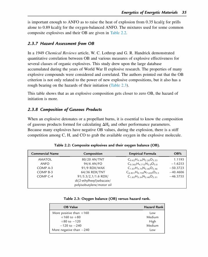
is important enough to ANFO as to raise the heat of explosion from 0.35 kcal/g for prills
alone to 0.89 kcal/g for the oxygen-balanced ANFO. The mixtures used for some common
composite explosives and their OB are given in Table 2.2.
2.3.7 Hazard Assessment from OB
In a 1949 Chemical Reviews article, W. C. Lothrop and G. R. Handrick demonstrated
quantitative correlation between OB and various measures of explosive effectiveness for
several classes of organic explosives. This study drew upon the large database
accumulated during the years of World War II explosive research. The properties of many
explosive compounds were considered and correlated. The authors pointed out that the OB
criterion is not only related to the power of new explosive compositions, but it also has a
rough bearing on the hazards of their initiation (Table 2.3).
This table shows that as an explosive composition gets closer to zero OB, the hazard of
initiation is more.
2.3.8 Composition of Gaseous Products
When an explosive detonates or a propellant burns, it is essential to know the composition
of gaseous products formed for calculating DHe and other performance parameters.
Because many explosives have negative OB values, during the explosion, there is a stiff
competition among C, H, and CO to grab the available oxygen in the explosive molecule.
Table 2.2: Composite explosives and their oxygen balance (OB).
Commercial Name Composition Empirical Formula OB%
AMATOL 80/20 AN/TNT C0.62H4.44N2.26O3.53 1.1193ANFO 94/6 AN/FO C0.365H4.713N2.0O3.0 �1.6253
COMP A-3 91/9 RDX/WAX C1.87H3.74N2.46O2.46 �50.3723COMP B-3 64/36 RDX/TNT C6.851H8.750N7.650O9.3 �40.4606COMP C-4 91/5.3/2,1/1.6 RDX/
di(2-ethylhexyl)sebacate/polyisobutylene/motor oil
C1.82H3.54N2.46O2.51 �46.3755
Table 2.3: Oxygen balance (OB) versus hazard rank.
OB Value Hazard Rank
More positive than þ160 Lowþ160 to þ80 Mediumþ80 to �120 High�120 to �240 Medium
More negative than �240 Low
Energetics of Energetic Materials 35
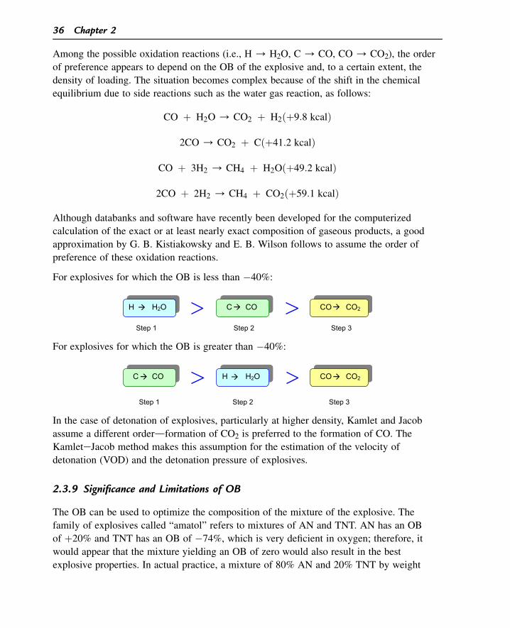
Among the possible oxidation reactions (i.e., H / H2O, C / CO, CO / CO2), the order
of preference appears to depend on the OB of the explosive and, to a certain extent, the
density of loading. The situation becomes complex because of the shift in the chemical
equilibrium due to side reactions such as the water gas reaction, as follows:
CO þ H2O / CO2 þ H2ðþ9:8 kcalÞ
2CO / CO2 þ Cðþ41:2 kcalÞ
CO þ 3H2 / CH4 þ H2Oðþ49:2 kcalÞ
2CO þ 2H2 / CH4 þ CO2ðþ59:1 kcalÞ
Although databanks and software have recently been developed for the computerized
calculation of the exact or at least nearly exact composition of gaseous products, a good
approximation by G. B. Kistiakowsky and E. B. Wilson follows to assume the order of
preference of these oxidation reactions.
For explosives for which the OB is less than �40%:
Step 1 Step 2 Step 3
H H2O C CO CO CO2
For explosives for which the OB is greater than �40%:
Step 1 Step 2 Step 3
H H2O C CO CO CO2
In the case of detonation of explosives, particularly at higher density, Kamlet and Jacob
assume a different orderdformation of CO2 is preferred to the formation of CO. The
KamleteJacob method makes this assumption for the estimation of the velocity of
detonation (VOD) and the detonation pressure of explosives.
2.3.9 Significance and Limitations of OB
The OB can be used to optimize the composition of the mixture of the explosive. The
family of explosives called “amatol” refers to mixtures of AN and TNT. AN has an OB
of þ20% and TNT has an OB of �74%, which is very deficient in oxygen; therefore, it
would appear that the mixture yielding an OB of zero would also result in the best
explosive properties. In actual practice, a mixture of 80% AN and 20% TNT by weight
36 Chapter 2
yields an OB of þ1%, the best properties of all mixtures, and an increase in the strength
of 30% over TNT.
The OB provides information on the types of gases liberated. The concept of OB is
particularly useful as a first guideline when formulating explosives to produce a minimum
of toxic fumes. An explosive with excess oxygen produces toxic nitric oxide and nitrogen
dioxide; an explosive with an oxygen deficiency produces toxic CO. Explosives for use
underground with poor ventilation should be formulated to produce a minimal total toxic
effect. If the OB is large and negative, then there is not enough oxygen for CO2 to be
formed; consequently, toxic gases such as CO will be liberated. This is very important for
commercial explosives because the amount of toxic gases liberated must be kept to a
minimum.
Sensitivity, brisance (shattering power), and strength are properties resulting from complex
explosive chemical reactions; therefore, a simple relationship such as OB cannot be
depended upon to yield universally consistent results. When using OB to predict properties
of one explosive relative to another, it is to be expected that one with an OB closer to zero
will be the more brisant, powerful, and sensitive; however, many exceptions to this rule do
exist.
2.3.10 Detonation Temperature/Flame Temperature
The temperature of the gas products on firing propellants in a gun is of considerable
importance in the study of ballistics and the erosion of a gun barrel. Likewise, the
detonation temperature in the case of high explosives is an important parameter because it
is related to the power of those explosives. Let us understand the variation of detonation/
flame temperatures under two different conditionsdat constant volume and at constant
pressure.
Case I (Constant Volume)
When a certain amount of explosive is initiated in a closed vessel that is thermally
insulated, let the total heat evolved be x calories. This heat of explosion is used to increase
the internal energy of the gases. Because the temperature is effectively a measure of the
internal energy of a system, the heat of explosion increases the temperature of the
products of explosion. The maximum temperature to which the decomposition products
are raised is called the “detonation temperature” in the case of an explosive and the “flame
temperature” when we talk about propellants. To be more specific, this temperature is also
called the “adiabatic, isochoric flame temperature” (adiabatic, thermally insulateddno
heat escapes from or enters inside of the system; isochoric, constant volume), abbreviated
as Tn. The isochoric flame temperature of explosives varies from as low as 2500 �C in the
case of nitroguanidine to 5000 �C in the case of NG.
Energetics of Energetic Materials 37
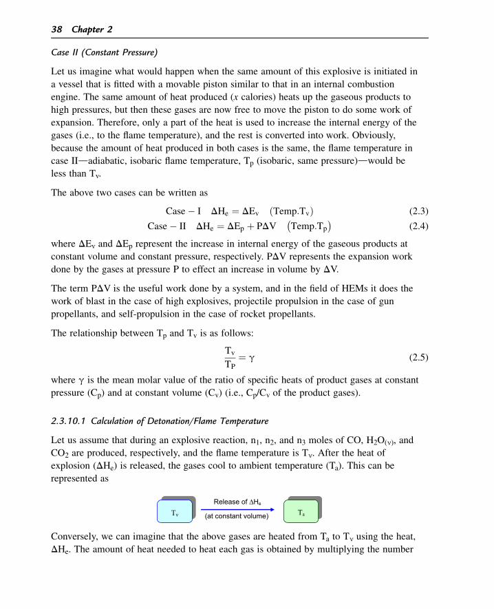
Case II (Constant Pressure)
Let us imagine what would happen when the same amount of this explosive is initiated in
a vessel that is fitted with a movable piston similar to that in an internal combustion
engine. The same amount of heat produced (x calories) heats up the gaseous products to
high pressures, but then these gases are now free to move the piston to do some work of
expansion. Therefore, only a part of the heat is used to increase the internal energy of the
gases (i.e., to the flame temperature), and the rest is converted into work. Obviously,
because the amount of heat produced in both cases is the same, the flame temperature in
case IIdadiabatic, isobaric flame temperature, Tp (isobaric, same pressure)dwould be
less than Tv.
The above two cases can be written as
Case� I DHe ¼ DEv ðTemp:TvÞ (2.3)
Case� II DHe ¼ DEp þ PDV�
Temp:Tp
�
(2.4)
where DEv and DEp represent the increase in internal energy of the gaseous products at
constant volume and constant pressure, respectively. PDV represents the expansion work
done by the gases at pressure P to effect an increase in volume by DV.
The term PDV is the useful work done by a system, and in the field of HEMs it does the
work of blast in the case of high explosives, projectile propulsion in the case of gun
propellants, and self-propulsion in the case of rocket propellants.
The relationship between Tp and Tv is as follows:
Tv
TP¼ g (2.5)
where g is the mean molar value of the ratio of specific heats of product gases at constant
pressure (Cp) and at constant volume (Cv) (i.e., Cp/Cv of the product gases).
2.3.10.1 Calculation of Detonation/Flame Temperature
Let us assume that during an explosive reaction, n1, n2, and n3 moles of CO, H2O(n), and
CO2 are produced, respectively, and the flame temperature is Tn. After the heat of
explosion (DHe) is released, the gases cool to ambient temperature (Ta). This can be
represented as
Release of ΔHe
(at constant volume) Tν Ta
Conversely, we can imagine that the above gases are heated from Ta to Tn using the heat,
DHe. The amount of heat needed to heat each gas is obtained by multiplying the number
38 Chapter 2
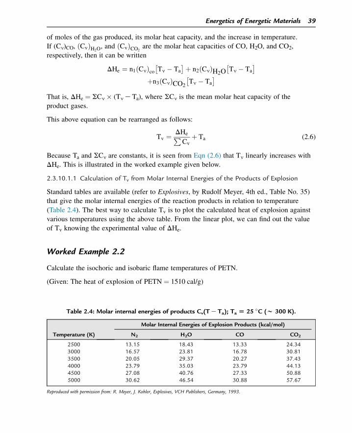
of moles of the gas produced, its molar heat capacity, and the increase in temperature.
If (Cn)CO, ðCvÞH2O, and ðCvÞCO2
are the molar heat capacities of CO, H2O, and CO2,
respectively, then it can be written
DHe ¼ n1ðCnÞco
Tn � Ta
þ n2ðCnÞH2O
Tn � Ta
þn3ðCnÞCO2
Tn � Ta
That is, DHe ¼ SCn � (Tn e Ta), where SCn is the mean molar heat capacity of the
product gases.
This above equation can be rearranged as follows:
Tv ¼ DHeP
Cvþ Ta (2.6)
Because Ta and SCn are constants, it is seen from Eqn (2.6) that Tn linearly increases with
DHe. This is illustrated in the worked example given below.
2.3.10.1.1 Calculation of Tv from Molar Internal Energies of the Products of Explosion
Standard tables are available (refer to Explosives, by Rudolf Meyer, 4th ed., Table No. 35)
that give the molar internal energies of the reaction products in relation to temperature
(Table 2.4). The best way to calculate Tv is to plot the calculated heat of explosion against
various temperatures using the above table. From the linear plot, we can find out the value
of Tv knowing the experimental value of DHe.
Worked Example 2.2
Calculate the isochoric and isobaric flame temperatures of PETN.
(Given: The heat of explosion of PETN ¼ 1510 cal/g)
Table 2.4: Molar internal energies of products Cv(T e Ta); Ta [ 25 �C (w 300 K).
Temperature (K)
Molar Internal Energies of Explosion Products (kcal/mol)
N2 H2O CO CO2
2500 13.15 18.43 13.33 24.343000 16.57 23.81 16.78 30.813500 20.05 29.37 20.27 37.434000 23.79 35.03 23.79 44.134500 27.08 40.76 27.33 50.885000 30.62 46.54 30.88 57.67
Reproduced with permission from: R. Meyer, J. Kohler, Explosives, VCH Publishers, Germany, 1993.
Energetics of Energetic Materials 39
PETN, C(CH2ONO2)4, or C5H8N4O12, undergoes the following explosive reaction:
C5H8N4O12ðMol:Wt¼316:1Þ
/ 2N2 þ 4H2OðvÞ þ 2COþ 3CO2
ðTotal: 11 moles of gasesÞ
We need the heat of explosion value in the unit of kilocalories per mol.
DHe ¼ 1510 cal=g ¼ 1510
1000� 316:1 ¼ 477:3 kcal=mol
The minimum and maximum values of flame temperature of explosives are approximately
2500 and 5000 K, respectively. We do not know the actual flame temperature of PETN,
although we are certain that it should be somewhere between 2500 and 5000 K. Using
Table 2.4, we can calculate the expected DHe values of PETN had its flame temperature
been 2500, 3000, 3500, 4000, 4500, or 5000 K.
For example, at 2500 K (or had the flame temperature been 2500 K), the expected cal.val
output by the products 2N2 þ 4H2O þ 2CO þ 3CO2 would be
DHeð2500Þ ¼ 2ð13:15Þ þ 4ð18:43Þ þ 2ð13:33Þ þ 3ð24:34Þ kcal=mol
¼ 199:70 kcal=mol:
A similar calculation yields DHe values of 254.37, 310.41, 367.67, 424.50, and
482.17 kcal/mol at 3000, 3500, 4000, 4500, and 5000 K, respectively. A plot of cal.val
versus assumed Tv (see Figure 2.11) yields a straight line.
Because the experimentally determined value for DHe is 477.3 kcal/mol, it can be read out
from the plot that the actual value for Tv is approximately 4960 K.
2.3.10.1.2 Calculation of Tp
Because Tp and Tv are related as Tv
Tp¼ g, we should calculate the molar average value of g
for all of the products. The values of g for N2, H2O, CO, and CO2 are 1.404, 1.324, 1.404,
and 1.304, respectively. The molar average of the products can be written as (remember
that there are 11 moles of the product gases in all)
g ¼�
2
11� 1:404
�
þ�
4
11� 1:324
�
þ�
2
11� 1:404
�
þ�
3
11� 1:304
�
¼ 1:348
Tp ¼ Tv
�
g ¼ 4960�
1:348 ¼ 3680 K
The above method of calculating flame temperature can be applied to compositions of
explosives and propellants once we know their DHe values and the composition of the
gaseous products.
40 Chapter 2
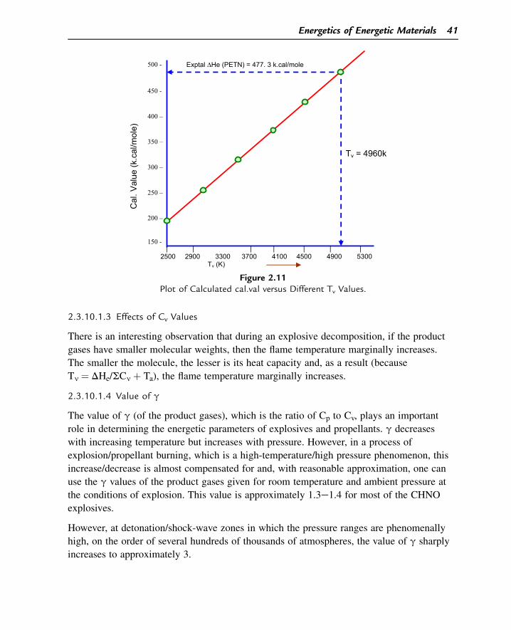
2.3.10.1.3 Effects of Cv Values
There is an interesting observation that during an explosive decomposition, if the product
gases have smaller molecular weights, then the flame temperature marginally increases.
The smaller the molecule, the lesser is its heat capacity and, as a result (because
Tn ¼ DHe/SCn þ Ta), the flame temperature marginally increases.
2.3.10.1.4 Value of g
The value of g (of the product gases), which is the ratio of Cp to Cv, plays an important
role in determining the energetic parameters of explosives and propellants. g decreases
with increasing temperature but increases with pressure. However, in a process of
explosion/propellant burning, which is a high-temperature/high pressure phenomenon, this
increase/decrease is almost compensated for and, with reasonable approximation, one can
use the g values of the product gases given for room temperature and ambient pressure at
the conditions of explosion. This value is approximately 1.3e1.4 for most of the CHNO
explosives.
However, at detonation/shock-wave zones in which the pressure ranges are phenomenally
high, on the order of several hundreds of thousands of atmospheres, the value of g sharply
increases to approximately 3.
500 -
450 -
400 –
350 –
300 –
250 –
200 –
150 -
Cal
. Val
ue (k
.cal
/mol
e)
Tv = 4960k
Exptal ΔHe (PETN) = 477. 3 k.cal/mole
| | | | | | | 2500 2900 3300 3700 4100 4500 4900 5300 Tv (K)
Figure 2.11Plot of Calculated cal.val versus Different Tv Values.
Energetics of Energetic Materials 41
Note: “Detonation temperature” and “flame temperature” are almost the same for a given
HEM because they refer to the temperature to which the products of explosion are
adiabatically heated by the heat of explosion. However, the term “explosion temperature”
(also sometimes referred to as “cook-off temperature”) is often used to refer to the
temperature at which the autoignition of an explosive commences when it is heated at a
particular rate. For example, the detonation temperature of NC is approximately 3470 K
whereas its explosion temperature is approximately 170 �C when it is heated at the rate of
5 �C/s. That is, when the temperature of NC reaches approximately 170 �C, theautoignition starts. There can be a slight variation in the values of the explosion
temperature of an explosive depending on the heat exchange conditions and the geometry
of the sample.
2.3.11 Gas Volume
When a certain quantity of explosive undergoes an explosive decomposition, it evolves
high-pressure/high-temperature gaseous products. Because of the high pressure, the gases
expand to reach the atmospheric pressure, and in the process of expansion, they do work.
Because the volume of a (solid) explosive is negligible in comparison to that of the
product gases, we can write
PV ¼ nRT (2.7)
where P, V, n, R, and T represent the final pressure after expansion, the final volume, the
number of moles of the gases produced, the universal gas constant, and the final
temperature, respectively. The volume of the gaseous products of expansion (V) is
generally calculated at the pressure of 1 bar and 273 K (i.e., at normal temperature and
pressure (NTP)). For explosives, the value of V varies from 700 to 1000 cc/g. That means
that in the case of most of explosives, the explosion of 1 g of an explosive produces
product gases that occupy a volume varying between 700 and 1000 cc when measured at
atmospheric pressure and 273 K.
Worked Example 2.3
Calculate the number of moles and the volume of the gaseous products of explosion of
RDX (C3H6O6N6).
The explosive reaction of RDX is given as
C3H6O6N6/3COþ 3H2OðvÞ þ 3N2
ðMol:Wt ¼ 222Þ
42 Chapter 2
There are 9 moles of gaseous products, including H2O, which is in vapor state. As a standard
practice, H2O is treated as vapor even when we calculate the total gas volume at NTP.
222 g of RDX evolves / 9 mol of gases ðat NTPÞ
Therefore; 1 g of RDX evolves / 9=222 mol of gases at NTP:
ðApplying Avogadro’s lawÞ/ 9
222� 22; 400 cc of gases at NTP ¼ 908 cc:
The gas volume of RDX explosion products ¼ 908 cc/g.
It is seen from the gas equation that at a given temperature and pressure, the volume of a
given gas directly depends on the number of moles of the gaseous products. Because the
volume generation is tantamount to the work of expansion, we can say that an explosive
that on decomposition produces more moles of the product gases (per gram of the
explosive) possesses better work potential. More moles of gases per gram of explosive
effectively means the product gases with lesser molecular weights.
2.3.12 The nRT Wonder
In Section 2.3.10, we presented the equation relating DHe and DE at constant pressure as
DHe ¼ DEþ PDV
DV refers to the change in volume when a solid explosive is converted into product gases.
As compared to the volume of product gases, the volume of the solid explosive can be
neglected (we have seen above that 1 g of RDX, which occupies a volume of 0.56 cc, on
explosion, gives product gases that occupy a volume of 908 cc). Therefore, in the above
equation, DV can be replaced by V, the volume of the product gases; that is,
DHe ¼ DE þ PV, and because PV ¼ nRT (assuming ideal gas behavior),
DHe ¼ DEþ nRT (2.8)
nRT is actually the work factor of an explosive decomposition. This term is very important
in the field of HEMs, and it manifests its importance in different forms under different
nomenclatures. As we will see in the respective chapters, the nRT factor manifests itself as
• Specific energy, which decides the strength or power of a high explosive;
• Impetus, or force constant, in gun propellants, which would decide how much muzzle
velocity and hence range can be imparted to a projectile; and
• A parameter in rocket propellants that is directly related to the specific impulse (Isp),
the ultimate energy index for any rocket propellant.
Energetics of Energetic Materials 43
Although in the first two cases we deal with an almost constant-volume condition (flame
temperature: Tn), in the case of rocket propellants we encounter a constant-pressure
condition (flame temperature: Tp). These will be discussed in a little more detail in the
respective chapters. The message is: “If we want an HEM with better work potential, then
the value of nRT must be higher, implying that for a given weight of the explosive/
propellant, it should produce more moles of product gases with higher flame temperature
(isochoric or isobaric depending on the function).”
Energy of Formation (DEf) versus Heat of Formation (DHf):
We defined DHf and explained its importance in Section 2.3.2. Now, having understood
the difference between DH and DE being the energy transition involved under constant
pressure and constant volume, respectively, let us see the relation between the energy of
formation (DEf) and the enthalpy of formation (DHf).
“DHf and DEf are the quantities of heat absorbed or evolved when 1 mole of a compound
is formed from its constituent elements at standard state (25 �C and 1 atm) at constant
pressure and constant volume, respectively.”
Worked Example 2.4
The enthalpy of formation of RDX is 76.1 cal/g. Calculate its energy of formation.
(Given: RDX: C3H6N6O6; molecular weight ¼ 222.1.)
The chemical equation for the formation of RDX can be written as
3C þ 3H2 þ 3N2 þ 3O2 / C3H6O6N6
Because C (carbon) and C3H6O6N6 (RDX) are solids under standard states, the change in
the number of moles of gaseous compounds will be
Dn ¼ moles of the gaseous products e moles of the gaseous
reactants ¼ 0 e (0 þ 3 þ 3 þ 3) ¼ e9.
Because DH ¼ DE þ DnRT (R ¼ universal gas constant ¼ 1.987 cal/K/mol), and
T ¼ standard temperature ¼ 25 �C ¼ 298 K, then we can write (76.1 � 222.1) ¼DE þ (�9)(1.987)(298). (Please note that cal/g must be converted into cal/mol by
multiplying by the molecular weight of RDX).
16,902 ¼ DE e 5329.
Therefore, DE ¼ 22,231 cal/mol.
¼ 22;231
222:1z100 cal=g
Energy of formation (DEf) of RDX ¼ 100 cal/g.
44 Chapter 2
On the basis of the data on the DEf values of explosives and their explosive decomposition
products, we can calculate their heat of explosion and perform a thermodynamic
calculation of the decomposition reactions.
2.3.13 Pressure of Explosion
It was stated that when an explosive undergoes deflagration in a closed vessel, high
pressure is produced because of the evolution of high-temperature gases in large amounts.
This pressure is an important parameter because when the product gases expand to do
some useful work, such as propulsion of a projectile through a gun barrel, the total amount
of work done by the gases is directly proportional to this pressure. The pressure of
explosion, Pe, is defined as the maximum static pressure achieved when a given weight of
explosive is burned in a closed vessel of fixed volume assuming adiabatic conditions. The
gas equation for this process is given as
PeðV� � aÞ ¼ nRTe
where V* is the volume of the closed vessel and a is the covolume correction necessitated
by the fact that at such high pressures, a gas tends to be nonideal and a certain correction
must be applied for the volume of gaseous molecules themselves. We will deal in more
detail in subsequent chapters about the nonideal behavior of gaseous products formed
during explosion during detonation and explosive deflagration.
(Note: The pressure of explosion should not be confused with detonation pressure. The
latter refers to the pressure that exists at the detonation zone (detonation front) when a
shock wave travels through the medium of the explosive, which will be discussed in the
next chapter.)
2.3.14 Density
Density is one of the important characteristics of explosives and propellants. It will be
shown later that an increase in density of a high explosive increases its VOD and brisance
(destructive fragmentation effect). The actual density of an explosive, referred to as the
“theoretical maximum density” (TMD), can be accurately determined by conventional
methods. However, when an explosive composition is processed and filled, say in a
warhead, the density of the composition is often slightly less because of very fine voids.
That is why maximum care is taken to maximize the density of the high-energy
composition to be close to the TMD.
In addition, in the case of propellants, the higher the density, the higher will be the
performance output. For example, if the volume of a cartridge case of a small arms
ammunition is limited, one would look for a propellant with high density so that more
weight of the propellant can be loaded in it. In the case of rocket propellants, even if a
Energetics of Energetic Materials 45
solid rocket propellant may be energetic, if its density is very low, then the weight of the
rocket propellant grain loadable in a rocket motor of limited volume will be too little to be
acceptable. Therefore, in the field of energetic materials, density is a parameter as
important as energy itself.
2.3.14.1 Density and Molecular Structure
The density of an explosive should depend on the nature of the molecules and the way
they are arranged or packed in a crystal lattice. In particular, the weight of a molecule and
its volume (effective molar volume) should be a dominant factor. L. T. Eremenko
established a linear relationship between the density of explosives (liquid and solid) and
their hydrogen content, classified the explosives under 12 groups depending on their
molecular structures (whether aliphatic or aromatic, with symmetrical or unsymmetrical
substituents, etc.), and evolved an empirical equation as follows:
r ¼ ai � KiH
where r represents the calculated density of the explosive at TMD. ai and Ki are constants,
the values of which depend on the molecular structure/group/homologue. H refers to the
weight percentage of hydrogen in the molecule (normally %H is from 0 to 6). An error of
not more than 2% in this method has been claimed.
To summarize, several vital parameters of HEMs dictate their ultimate performance
characteristics. The inter-relationships among them are schematically shown in Figure 2.12.
Summary of Important Terms
1. Heat of reaction
The quantity of heat evolved or absorbed during a chemical reaction is called the
“heat of reaction.”
2. Enthalpy of reaction
If the chemical reactions occur at constant pressure, then the heat of reaction is often
called the “enthalpy of reaction.”
3. Endothermic reaction
A reaction in which energy is supplied to the reactants from the surroundings to obtain
the product is called an “endothermic reaction.”
4. Exothermic reaction
A reaction in which heat energy is evolved along with the products is called an
“exothermic reaction.”
5. Heat
Heat is one form of energy and can be produced from work. However, it is not
completely convertible into work. It can only partly be transformed into work. In this
respect, heat differs from many other forms of energy.
46 Chapter 2
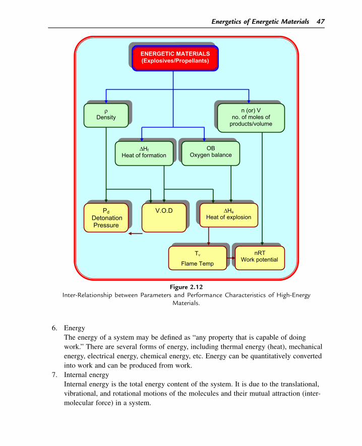
6. Energy
The energy of a system may be defined as “any property that is capable of doing
work.” There are several forms of energy, including thermal energy (heat), mechanical
energy, electrical energy, chemical energy, etc. Energy can be quantitatively converted
into work and can be produced from work.
7. Internal energy
Internal energy is the total energy content of the system. It is due to the translational,
vibrational, and rotational motions of the molecules and their mutual attraction (inter-
molecular force) in a system.
ENERGETIC MATERIALS (Explosives/Propellants)
ρDensity
ΔHfHeat of formation
OB Oxygen balance
n (or) Vno. of moles of
products/volume
Pd Detonation Pressure
V.O.D ΔHeHeat of explosion
nRT Work potential
Tν
Flame Temp
Figure 2.12Inter-Relationship between Parameters and Performance Characteristics of High-Energy
Materials.
Energetics of Energetic Materials 47
8. Resonance
Resonance is the possible existence of several types of bonding within a fixed skeleton
structure of a molecule by the mobility of double bonds. In more modern terminology,
the additional stability is brought about by the formation of a delocalized molecular
orbital of p electrons.
9. Hess’s law
Hess law states that “If a chemical reaction is carried out in stages, the algebraic sum
of the amounts of heat evolved in separate stages is equal to the total amount of heat
evolved when the reaction occurs directly.”
10. Heat of combustion (DHc)
It is defined as the heat evolved when 1 mole of a compound is completely burnt in
excess of oxygen.
11. Oxygen balance
The percentage excess or deficit of oxygen present in a compound required for its
complete oxidation to CO2, H2O, etc., is known as the OB of that compound. OB is a
method of quantifying how well an explosive provides its own oxidant.
12 Detonation temperature
The maximum temperature to which the decomposition products are raised is called
the “detonation temperature” in the case of explosives and “flame temperature” when
we talk about propellants.
13. Adiabatic, isochoric flame temperature
The flame temperature of the products of explosion of an explosive under adiabatic
(thermally insulated), isochoric (constant volume) conditions. It is abbreviated as Tn.
14. Adiabatic, isobaric flame temperature
Flame temperature of the products of explosion of an explosive under adiabatic,
isobaric (constant pressure) conditions. It is abbreviated as Tp. Tp is less than Tv.
15. Explosion temperature/autoignition temperature
The temperature at which the autoignition of an explosive commences when it is
heated at a particular rate.
16. Pressure of explosion PeThe pressure of explosion (Pe) is defined as the maximum static pressure achieved
when a given weight of explosive is burned in a closed vessel of fixed volume
assuming adiabatic conditions.
Suggested Reading
Any standard book on Physical Chemistry would discuss various aspects of thermochemistry. Apart from this,the reader might refer to the following books.[1] A. Bailey, S.G. Murray, Explosives, Propellants, and Pyrotechnics, Pergamon Press, Oxford, New York,
1988.[2] Service Textbook of Explosives, Min. of Defence, Publication, UK, 1972.
48 Chapter 2
[3] Structure and properties of energetic materials, in: D.H. Liebenberg, et al. (Eds.), Materials ResearchSociety, 1993. Pennsylvania, USA.
[4] P.W. Cooper, Explosives Engineering, VCH, Publishers Inc., USA, 1996.[5] B. Siegel, L. Schieler, Energetics of Propellant Chemistry, John Wiley & Sons. Inc., New York, 1964.[6] S.F. Sarner, Propellant Chemistry, Reinhold publishing corporation, New York, 1966.[7] L. Pauling, Nature of the Chemical Bond, third ed., Cornell University Press, Ithaca, 1960.
Questions
1. The heat of explosion of TNT is 1080 cal/g. If 1 kg of TNT detonates in 2 ms, how
much power does it generate? (Answer: 2.2572 � 1012 W)
(Note: The above question is hypothetical. The Second Law of Thermodynamics is
very much there to ban us from converting the entire heat to useful work.)
2. Why can we describe explosives as metastable materials?
3. When an explosives chemist wants to synthesize a new, high-performing explosive,
what parameters should his target molecule satisfy?
4. Why does one prefer to have a HEM with a positive heat of formation?
5. Calculate the OB of PETN. (Answer: 60.76%)
6. An explosive has a unique value of heat of combustion whereas its exact value of heat
of explosion depends on the conditions of its experimental determination. Why?
7. Why does zero OB help to achieve highest value of heat of explosion?
8. What is meant by isochoric and isobaric flame temperatures (Tn and Tp respectively)?
How are they related to each other? Why is Tn always more than Tp?
9. Calculate the isochoric and isobaric flame temperatures of HMX (molecular formula
C4H8N8O8). (Given: Heat of explosion of HMX ¼ 1480 cal/g.) (Hint: Use the molar
internal energies table given in Section 2.3.7.1.)
(Answer: Tv w 4580 K, Tp w 3326 K.)
10. What is the importance of the gas volume for an explosive? Calculate the volume of
the gaseous products of the explosion of 1 g of NG (molecular formula C3H5N3O9)
measured at NTP. Assume water as water vapor. (Answer: 715.1 mL)
11. Which parameter decides the work potential of an HEM? What different names does it
assume for a high explosive, a gun propellant, and a rocket propellant?
12. Name some methods used for the theoretical prediction of the heat of formation of a
molecule.
13. What is the general method used to measure the detonation temperature of a high
explosive?
14. What is the difference between explosion temperature and flame temperature?
15. Define heat of formation (DHf) and energy of formation (DEf) and state how they are
related to each other.
16. Define pressure of explosion (Pe) and write the gas equation for this process.
Energetics of Energetic Materials 49

This page intentionally left blank
CHAPTER 3
Two Faces of Explosion:Deflagration and Detonation
3.1 Explosion
Explosion is one of the most common words used in our day-to-day life. “Bursting” and
“detonation” are the words that appear to be synonymous with the word “explosion.” In a
way, “explosion” is a loosely used word implying different meanings under different
situations. We say, “a balloon explodes,” “a warhead or a bomb explodes,” “a nuclear
weapon explodes,” “a gas cylinder explodes,” “a reaction vessel explodes,” and so on (not
to mention its figurative usage such as “a boss explodes” or “a wife explodes”). although
all of these situations vary greatly in terms of
• The type of energy release (physical/chemical/nuclear)
• The quantum of energy released, and
• The rate at which the energy is released.
Before we try to get the correct definition of the word “explosion,” let us see how an
explosion can be classified. There are three types of explosions: (1) physical explosions,
(2) chemical explosions, and (3) nuclear explosions.
Physical explosions involve very fast physical transformation of a system or material that
results in an explosion. An example is the explosion of an overheated water boiler. No
chemical change takes place in this process. Only water in the liquid state gets converted
into its vapor state. Because the water vapor occupies a much larger volume than liquid
(water) at its boiling point, the pressure developed by the water vapor in a confined
volume of the boiler is so high that it overcomes the strength of the container material,
leading to sudden energy release.
On the other hand, nuclear explosions are disastrous because of the enormous amount of
thermal energy and radioactivity released due to the conversion of mass into energy
obeying the well-known equation of Einstein, E ¼ mc2.
This chapter excludes the above two types of explosions (physical and nuclear) and deals
only with chemical explosions, in which a large amount of thermal energy, often
accompanied by the evolution of a large amount of high-pressure, high-temperature
gaseous products, is suddenly released because of a chemical reaction. Coming back to the
Demystifying Explosives: Concepts in High Energy Materials. http://dx.doi.org/10.1016/B978-0-12-801576-6.00003-3
Copyright © 2015 Elsevier Inc. All rights reserved. 51
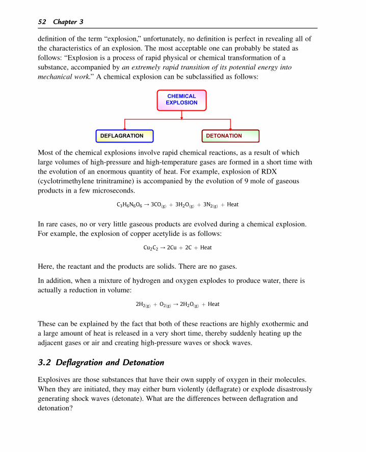
definition of the term “explosion,” unfortunately, no definition is perfect in revealing all of
the characteristics of an explosion. The most acceptable one can probably be stated as
follows: “Explosion is a process of rapid physical or chemical transformation of a
substance, accompanied by an extremely rapid transition of its potential energy into
mechanical work.” A chemical explosion can be subclassified as follows:
DEFLAGRATION DETONATION
CHEMICAL EXPLOSION
Most of the chemical explosions involve rapid chemical reactions, as a result of which
large volumes of high-pressure and high-temperature gases are formed in a short time with
the evolution of an enormous quantity of heat. For example, explosion of RDX
(cyclotrimethylene trinitramine) is accompanied by the evolution of 9 mole of gaseous
products in a few microseconds.
C3H6N6O6 / 3COðgÞ þ 3H2OðgÞ þ 3N2ðgÞ þ Heat
In rare cases, no or very little gaseous products are evolved during a chemical explosion.
For example, the explosion of copper acetylide is as follows:
Cu2C2 / 2Cu þ 2C þ Heat
Here, the reactant and the products are solids. There are no gases.
In addition, when a mixture of hydrogen and oxygen explodes to produce water, there is
actually a reduction in volume:
2H2ðgÞ þ O2ðgÞ / 2H2OðgÞ þ Heat
These can be explained by the fact that both of these reactions are highly exothermic and
a large amount of heat is released in a very short time, thereby suddenly heating up the
adjacent gases or air and creating high-pressure waves or shock waves.
3.2 Deflagration and Detonation
Explosives are those substances that have their own supply of oxygen in their molecules.
When they are initiated, they may either burn violently (deflagrate) or explode disastrously
generating shock waves (detonate). What are the differences between deflagration and
detonation?
52 Chapter 3
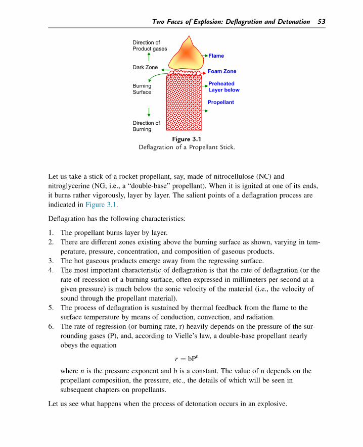
Let us take a stick of a rocket propellant, say, made of nitrocellulose (NC) and
nitroglycerine (NG; i.e., a “double-base” propellant). When it is ignited at one of its ends,
it burns rather vigorously, layer by layer. The salient points of a deflagration process are
indicated in Figure 3.1.
Deflagration has the following characteristics:
1. The propellant burns layer by layer.
2. There are different zones existing above the burning surface as shown, varying in tem-
perature, pressure, concentration, and composition of gaseous products.
3. The hot gaseous products emerge away from the regressing surface.
4. The most important characteristic of deflagration is that the rate of deflagration (or the
rate of recession of a burning surface, often expressed in millimeters per second at a
given pressure) is much below the sonic velocity of the material (i.e., the velocity of
sound through the propellant material).
5. The process of deflagration is sustained by thermal feedback from the flame to the
surface temperature by means of conduction, convection, and radiation.
6. The rate of regression (or burning rate, r) heavily depends on the pressure of the sur-
rounding gases (P), and, according to Vielle’s law, a double-base propellant nearly
obeys the equation
r ¼ bPn
where n is the pressure exponent and b is a constant. The value of n depends on the
propellant composition, the pressure, etc., the details of which will be seen in
subsequent chapters on propellants.
Let us see what happens when the process of detonation occurs in an explosive.
Direction of Product gases
Dark Zone
Burning Surface
Direction of Burning
Flame
Foam Zone
Preheated Layer below
Propellant
Figure 3.1Deflagration of a Propellant Stick.
Two Faces of Explosion: Deflagration and Detonation 53
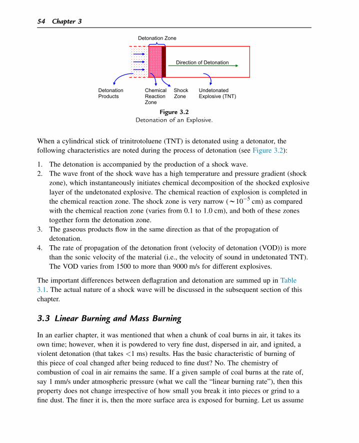
When a cylindrical stick of trinitrotoluene (TNT) is detonated using a detonator, the
following characteristics are noted during the process of detonation (see Figure 3.2):
1. The detonation is accompanied by the production of a shock wave.
2. The wave front of the shock wave has a high temperature and pressure gradient (shock
zone), which instantaneously initiates chemical decomposition of the shocked explosive
layer of the undetonated explosive. The chemical reaction of explosion is completed in
the chemical reaction zone. The shock zone is very narrow (w10�5 cm) as compared
with the chemical reaction zone (varies from 0.1 to 1.0 cm), and both of these zones
together form the detonation zone.
3. The gaseous products flow in the same direction as that of the propagation of
detonation.
4. The rate of propagation of the detonation front (velocity of detonation (VOD)) is more
than the sonic velocity of the material (i.e., the velocity of sound in undetonated TNT).
The VOD varies from 1500 to more than 9000 m/s for different explosives.
The important differences between deflagration and detonation are summed up in Table
3.1. The actual nature of a shock wave will be discussed in the subsequent section of this
chapter.
3.3 Linear Burning and Mass Burning
In an earlier chapter, it was mentioned that when a chunk of coal burns in air, it takes its
own time; however, when it is powdered to very fine dust, dispersed in air, and ignited, a
violent detonation (that takes <1 ms) results. Has the basic characteristic of burning of
this piece of coal changed after being reduced to fine dust? No. The chemistry of
combustion of coal in air remains the same. If a given sample of coal burns at the rate of,
say 1 mm/s under atmospheric pressure (what we call the “linear burning rate”), then this
property does not change irrespective of how small you break it into pieces or grind to a
fine dust. The finer it is, then the more surface area is exposed for burning. Let us assume
Detonation Zone
Direction of Detonation
Detonation Chemical Shock Undetonated Products Reaction Zone Explosive (TNT)
Zone
Figure 3.2Detonation of an Explosive.
54 Chapter 3
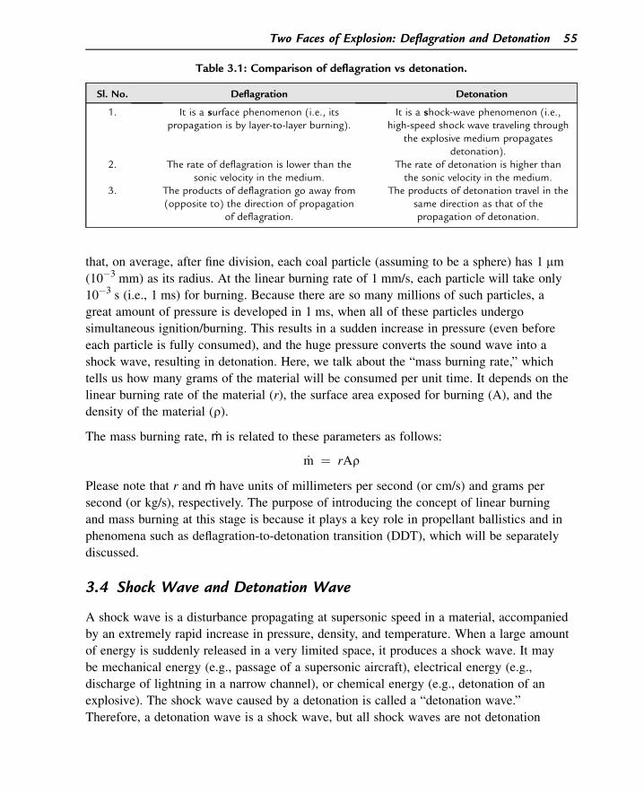
that, on average, after fine division, each coal particle (assuming to be a sphere) has 1 mm
(10�3 mm) as its radius. At the linear burning rate of 1 mm/s, each particle will take only
10�3 s (i.e., 1 ms) for burning. Because there are so many millions of such particles, a
great amount of pressure is developed in 1 ms, when all of these particles undergo
simultaneous ignition/burning. This results in a sudden increase in pressure (even before
each particle is fully consumed), and the huge pressure converts the sound wave into a
shock wave, resulting in detonation. Here, we talk about the “mass burning rate,” which
tells us how many grams of the material will be consumed per unit time. It depends on the
linear burning rate of the material (r), the surface area exposed for burning (A), and the
density of the material (r).
The mass burning rate, ṁ is related to these parameters as follows:
_m ¼ rAr
Please note that r and ṁ have units of millimeters per second (or cm/s) and grams per
second (or kg/s), respectively. The purpose of introducing the concept of linear burning
and mass burning at this stage is because it plays a key role in propellant ballistics and in
phenomena such as deflagration-to-detonation transition (DDT), which will be separately
discussed.
3.4 Shock Wave and Detonation Wave
A shock wave is a disturbance propagating at supersonic speed in a material, accompanied
by an extremely rapid increase in pressure, density, and temperature. When a large amount
of energy is suddenly released in a very limited space, it produces a shock wave. It may
be mechanical energy (e.g., passage of a supersonic aircraft), electrical energy (e.g.,
discharge of lightning in a narrow channel), or chemical energy (e.g., detonation of an
explosive). The shock wave caused by a detonation is called a “detonation wave.”
Therefore, a detonation wave is a shock wave, but all shock waves are not detonation
Table 3.1: Comparison of deflagration vs detonation.
Sl. No. Deflagration Detonation
1. It is a surface phenomenon (i.e., itspropagation is by layer-to-layer burning).
It is a shock-wave phenomenon (i.e.,high-speed shock wave traveling through
the explosive medium propagatesdetonation).
2. The rate of deflagration is lower than thesonic velocity in the medium.
The rate of detonation is higher thanthe sonic velocity in the medium.
3. The products of deflagration go away from(opposite to) the direction of propagation
of deflagration.
The products of detonation travel in thesame direction as that of thepropagation of detonation.
Two Faces of Explosion: Deflagration and Detonation 55
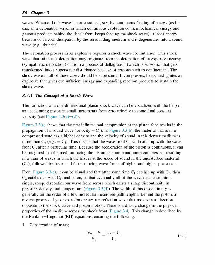
waves. When a shock wave is not sustained, say, by continuous feeding of energy (as in
case of a detonation wave, in which continuous evolution of thermochemical energy and
gaseous products behind the shock front keeps feeding the shock wave), it loses energy
because of viscous dissipation by the surrounding medium and it degenerates into a sound
wave (e.g., thunder).
The detonation process in an explosive requires a shock wave for initiation. This shock
wave that initiates a detonation may originate from the detonation of an explosive nearby
(sympathetic detonation) or from a process of deflagration (which is subsonic) that gets
transformed into a supersonic disturbance because of reasons such as confinement. The
shock wave in all of these cases should be supersonic. It compresses, heats, and ignites an
explosive that gives out sufficient energy and expanding reaction products to sustain the
shock wave.
3.4.1 The Concept of a Shock Wave
The formation of a one-dimensional planar shock wave can be visualized with the help of
an accelerating piston in small increments from zero velocity to some final constant
velocity (see Figure 3.3(a)e(d)).
Figure 3.3(a) shows that the first infinitesimal compression at the piston face results in the
propagation of a sound wave (velocity ¼ Co). In Figure 3.3(b), the material that is in a
compressed state has a higher density and the velocity of sound in this denser medium is
more than Co (e.g., ¼ C1). This means that the wave front C1 will catch up with the wave
front Co after a particular time. Because the acceleration of the piston is continuous, it can
be imagined that the medium facing the piston gets more and more compressed, resulting
in a train of waves in which the first is at the speed of sound in the undisturbed material
(Co), followed by faster and faster moving wave fronts of higher and higher pressures.
From Figure 3.3(c), it can be visualized that after some time C1 catches up with Co, then
C2 catches up with C1, and so on, so that eventually all of the waves coalesce into a
single, steep, discontinuous wave front across which exists a sharp discontinuity in
pressure, density, and temperature (Figure 3.3(d)). The width of this discontinuity is
generally on the order of a few molecular mean-free-path lengths. Behind the piston, a
reverse process of gas expansion creates a rarefaction wave that moves in a direction
opposite to the shock wave and piston motion. There is a drastic change in the physical
properties of the medium across the shock front (Figure 3.4). This change is described by
the RankineeHugoniot (RH) equations, ensuring the following:
1. Conservation of mass;
Vo � V
Vo¼ Up � Uo
Us(3.1)
56 Chapter 3
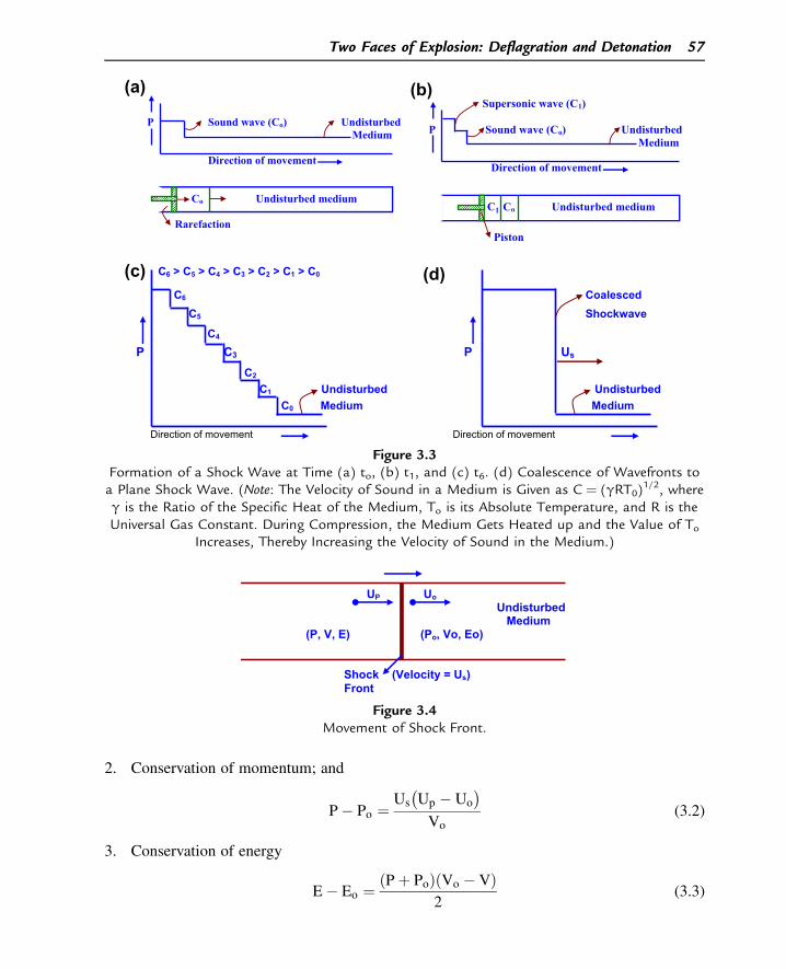
2. Conservation of momentum; and
P� Po ¼Us
�
Up � Uo
�
Vo(3.2)
3. Conservation of energy
E� Eo ¼ ðPþ PoÞðVo � VÞ2
(3.3)
C6 > C5 > C4 > C3 > C2 > C1 > C0
C6 CoalescedC5 Shockwave
C4
P C3 P Us
C2
C1 Undisturbed Undisturbed C0 Medium Medium
Direction of movement Direction of movement
P Sound wave (Co) Undisturbed Medium
Direction of movement
Co Undisturbed medium
Rarefaction
Supersonic wave (C1)
P Sound wave (Co) Undisturbed Medium
Direction of movement
C1 Co Undisturbed medium
Piston
(a) (b)
(c) (d)
Figure 3.3Formation of a Shock Wave at Time (a) to, (b) t1, and (c) t6. (d) Coalescence of Wavefronts toa Plane Shock Wave. (Note: The Velocity of Sound in a Medium is Given as C ¼ (gRT0)
1/2, whereg is the Ratio of the Specific Heat of the Medium, To is its Absolute Temperature, and R is theUniversal Gas Constant. During Compression, the Medium Gets Heated up and the Value of To
Increases, Thereby Increasing the Velocity of Sound in the Medium.)
UP Uo Undisturbed Medium
(P, V, E) (Po, Vo, Eo)
Shock (Velocity = Us) Front
Figure 3.4Movement of Shock Front.
Two Faces of Explosion: Deflagration and Detonation 57
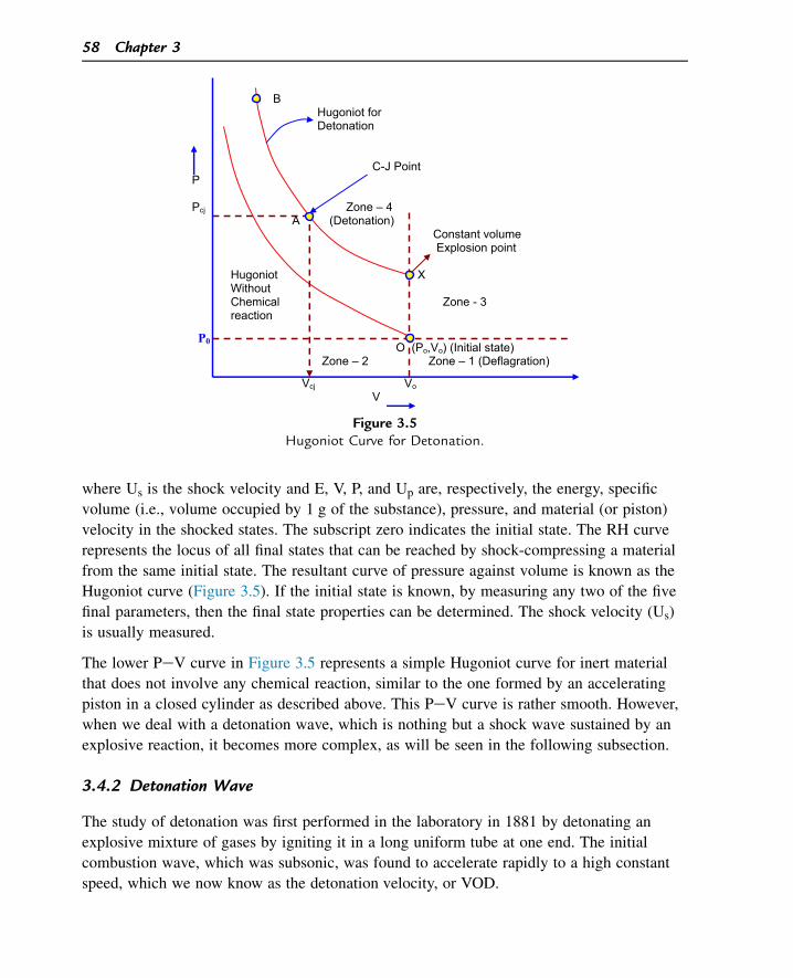
where Us is the shock velocity and E, V, P, and Up are, respectively, the energy, specific
volume (i.e., volume occupied by 1 g of the substance), pressure, and material (or piston)
velocity in the shocked states. The subscript zero indicates the initial state. The RH curve
represents the locus of all final states that can be reached by shock-compressing a material
from the same initial state. The resultant curve of pressure against volume is known as the
Hugoniot curve (Figure 3.5). If the initial state is known, by measuring any two of the five
final parameters, then the final state properties can be determined. The shock velocity (Us)
is usually measured.
The lower PeV curve in Figure 3.5 represents a simple Hugoniot curve for inert material
that does not involve any chemical reaction, similar to the one formed by an accelerating
piston in a closed cylinder as described above. This PeV curve is rather smooth. However,
when we deal with a detonation wave, which is nothing but a shock wave sustained by an
explosive reaction, it becomes more complex, as will be seen in the following subsection.
3.4.2 Detonation Wave
The study of detonation was first performed in the laboratory in 1881 by detonating an
explosive mixture of gases by igniting it in a long uniform tube at one end. The initial
combustion wave, which was subsonic, was found to accelerate rapidly to a high constant
speed, which we now know as the detonation velocity, or VOD.
B Hugoniot for Detonation
C-J Point P
Pcj Zone – 4 A (Detonation)
Constant volume Explosion point
Hugoniot X Without Chemical Zone - 3 reaction
O (Po,Vo) (Initial state) Zone – 2 Zone – 1 (Deflagration)
Vcj Vo V
P0
Figure 3.5Hugoniot Curve for Detonation.
58 Chapter 3
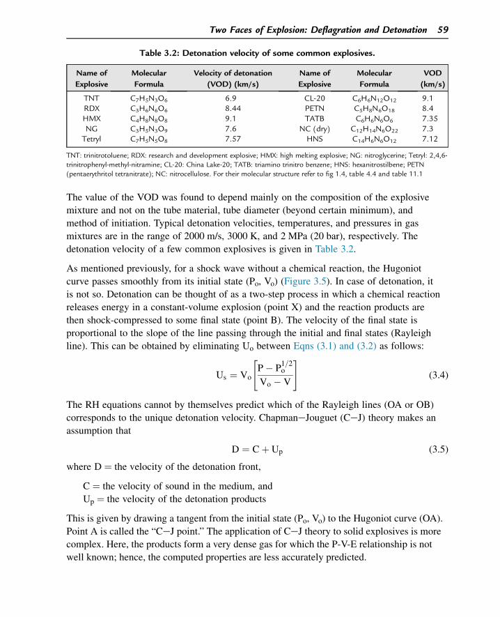
The value of the VOD was found to depend mainly on the composition of the explosive
mixture and not on the tube material, tube diameter (beyond certain minimum), and
method of initiation. Typical detonation velocities, temperatures, and pressures in gas
mixtures are in the range of 2000 m/s, 3000 K, and 2 MPa (20 bar), respectively. The
detonation velocity of a few common explosives is given in Table 3.2.
As mentioned previously, for a shock wave without a chemical reaction, the Hugoniot
curve passes smoothly from its initial state (Po, Vo) (Figure 3.5). In case of detonation, it
is not so. Detonation can be thought of as a two-step process in which a chemical reaction
releases energy in a constant-volume explosion (point X) and the reaction products are
then shock-compressed to some final state (point B). The velocity of the final state is
proportional to the slope of the line passing through the initial and final states (Rayleigh
line). This can be obtained by eliminating Uo between Eqns (3.1) and (3.2) as follows:
Us ¼ Vo
"
P� P1=2o
Vo � V
#
(3.4)
The RH equations cannot by themselves predict which of the Rayleigh lines (OA or OB)
corresponds to the unique detonation velocity. ChapmaneJouguet (CeJ) theory makes an
assumption that
D ¼ Cþ Up (3.5)
where D ¼ the velocity of the detonation front,
C ¼ the velocity of sound in the medium, and
Up ¼ the velocity of the detonation products
This is given by drawing a tangent from the initial state (Po, Vo) to the Hugoniot curve (OA).
Point A is called the “CeJ point.” The application of CeJ theory to solid explosives is more
complex. Here, the products form a very dense gas for which the P-V-E relationship is not
well known; hence, the computed properties are less accurately predicted.
Table 3.2: Detonation velocity of some common explosives.
Name of
Explosive
Molecular
Formula
Velocity of detonation
(VOD) (km/s)
Name of
Explosive
Molecular
Formula
VOD
(km/s)
TNT C7H5N3O6 6.9 CL-20 C6H6N12O12 9.1RDX C3H6N6O6 8.44 PETN C5H8N6O18 8.4HMX C4H8N8O8 9.1 TATB C6H6N6O6 7.35NG C3H5N3O9 7.6 NC (dry) C12H14N6O22 7.3Tetryl C7H5N5O8 7.57 HNS C14H6N6O12 7.12
TNT: trinitrotoluene; RDX: research and development explosive; HMX: high melting explosive; NG: nitroglycerine; Tetryl: 2,4,6-trinitrophenyl-methyl-nitramine; CL-20: China Lake-20; TATB: triamino trinitro benzene; HNS: hexanitrostilbene; PETN(pentaerythritol tetranitrate); NC: nitrocellulose. For their molecular structure refer to fig 1.4, table 4.4 and table 11.1
Two Faces of Explosion: Deflagration and Detonation 59
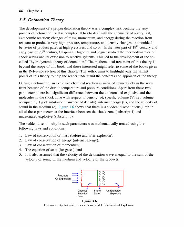
3.5 Detonation Theory
The development of a proper detonation theory was a complex task because the very
process of detonation itself is complex. It has to deal with the chemistry of a very fast,
exothermic reaction; changes of mass, momentum, and energy during the reaction from
reactant to products; very high pressure, temperature, and density changes; the nonideal
behavior of product gases at high pressures; and so on. In the later part of 19th century and
early part of 20th century, Chapman, Hugoniot and Joguet studied the thermodynamics of
shock waves and its extension to reactive systems. This led to the development of the so-
called “hydrodynamic theory of detonation.” The mathematical treatment of this theory is
beyond the scope of this book, and those interested might refer to some of the books given
in the Reference section of this chapter. The author aims to highlight only the salient
points of this theory to help the reader understand the concepts and approach of the theory.
During a detonation, an explosive chemical reaction is initiated immediately in the wave
front because of the drastic temperature and pressure conditions. Apart from these two
parameters, there is a significant difference between the undetonated explosive and the
molecules in the shock zone with respect to density (r), specific volume (V; i.e., volume
occupied by 1 g of substance e inverse of density), internal energy (E), and the velocity of
sound in the medium (c). Figure 3.6 shows that there is a sudden, discontinuous jump in
all of these parameters at the interface between the shock zone (subscript 1) and
undetonated explosive (subscript o).
The sudden discontinuity in such parameters was mathematically treated using the
following laws and conditions:
1. Law of conservation of mass (before and after explosion),
2. Law of conservation of energy (internal energy),
3. Law of conservation of momentum,
4. The equation of state (for gases), and
5. It is also assumed that the velocity of the detonation wave is equal to the sum of the
velocity of sound in the medium and velocity of the products.
PTρVEC
PTρVEC
Chemical Shock Undetonated Reaction Zone Explosive Zone
Products Of Explosion
Figure 3.6Discontinuity between Shock Zone and Undetonated Explosive.
60 Chapter 3
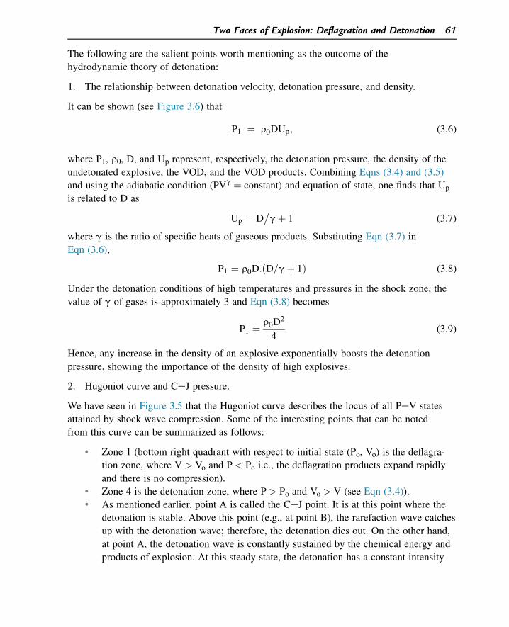
The following are the salient points worth mentioning as the outcome of the
hydrodynamic theory of detonation:
1. The relationship between detonation velocity, detonation pressure, and density.
It can be shown (see Figure 3.6) that
P1 ¼ r0DUp; (3.6)
where P1, r0, D, and Up represent, respectively, the detonation pressure, the density of the
undetonated explosive, the VOD, and the VOD products. Combining Eqns (3.4) and (3.5)
and using the adiabatic condition (PVg ¼ constant) and equation of state, one finds that Up
is related to D as
Up ¼ D�
gþ 1 (3.7)
where g is the ratio of specific heats of gaseous products. Substituting Eqn (3.7) in
Eqn (3.6),
P1 ¼ r0D:ðD=gþ 1Þ (3.8)
Under the detonation conditions of high temperatures and pressures in the shock zone, the
value of g of gases is approximately 3 and Eqn (3.8) becomes
P1 ¼ r0D2
4(3.9)
Hence, any increase in the density of an explosive exponentially boosts the detonation
pressure, showing the importance of the density of high explosives.
2. Hugoniot curve and CeJ pressure.
We have seen in Figure 3.5 that the Hugoniot curve describes the locus of all PeV states
attained by shock wave compression. Some of the interesting points that can be noted
from this curve can be summarized as follows:
• Zone 1 (bottom right quadrant with respect to initial state (Po, Vo) is the deflagra-
tion zone, where V > Vo and P < Po i.e., the deflagration products expand rapidly
and there is no compression).
• Zone 4 is the detonation zone, where P > Po and Vo > V (see Eqn (3.4)).
• As mentioned earlier, point A is called the CeJ point. It is at this point where the
detonation is stable. Above this point (e.g., at point B), the rarefaction wave catches
up with the detonation wave; therefore, the detonation dies out. On the other hand,
at point A, the detonation wave is constantly sustained by the chemical energy and
products of explosion. At this steady state, the detonation has a constant intensity
Two Faces of Explosion: Deflagration and Detonation 61
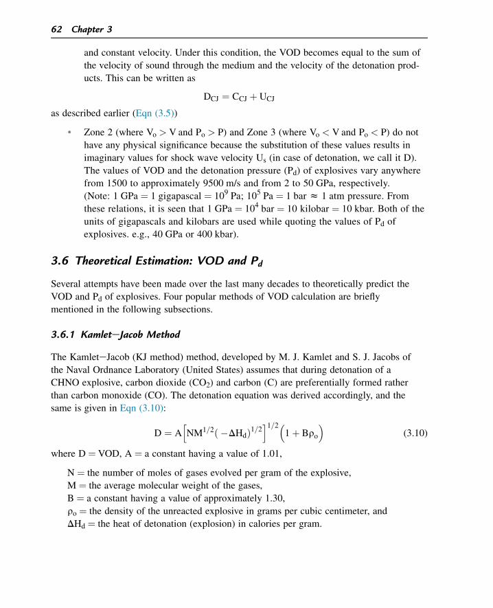
and constant velocity. Under this condition, the VOD becomes equal to the sum of
the velocity of sound through the medium and the velocity of the detonation prod-
ucts. This can be written as
DCJ ¼ CCJ þ UCJ
as described earlier (Eqn (3.5))
• Zone 2 (where Vo > V and Po > P) and Zone 3 (where Vo < V and Po < P) do not
have any physical significance because the substitution of these values results in
imaginary values for shock wave velocity Us (in case of detonation, we call it D).
The values of VOD and the detonation pressure (Pd) of explosives vary anywhere
from 1500 to approximately 9500 m/s and from 2 to 50 GPa, respectively.
(Note: 1 GPa ¼ 1 gigapascal ¼ 109 Pa; 105 Pa ¼ 1 bar z 1 atm pressure. From
these relations, it is seen that 1 GPa ¼ 104 bar ¼ 10 kilobar ¼ 10 kbar. Both of the
units of gigapascals and kilobars are used while quoting the values of Pd of
explosives. e.g., 40 GPa or 400 kbar).
3.6 Theoretical Estimation: VOD and Pd
Several attempts have been made over the last many decades to theoretically predict the
VOD and Pd of explosives. Four popular methods of VOD calculation are briefly
mentioned in the following subsections.
3.6.1 KamleteJacob Method
The KamleteJacob (KJ method) method, developed by M. J. Kamlet and S. J. Jacobs of
the Naval Ordnance Laboratory (United States) assumes that during detonation of a
CHNO explosive, carbon dioxide (CO2) and carbon (C) are preferentially formed rather
than carbon monoxide (CO). The detonation equation was derived accordingly, and the
same is given in Eqn (3.10):
D ¼ Ah
NM1=2ð �DHdÞ1=2i1=2�
1þ Bro
�
(3.10)
where D ¼ VOD, A ¼ a constant having a value of 1.01,
N ¼ the number of moles of gases evolved per gram of the explosive,
M ¼ the average molecular weight of the gases,
B ¼ a constant having a value of approximately 1.30,
ro ¼ the density of the unreacted explosive in grams per cubic centimeter, and
DHd ¼ the heat of detonation (explosion) in calories per gram.
62 Chapter 3
Example: Let us calculate the VOD of TNT, having molecular formula C7H5N3O6, at its
density of 1.64 g/cc. The heat of detonation is 1090 cal/g.
Step 1: Write the detonation equation.
C7H5N3O6 / 1:5N2ðgÞ þ 2:5H2OðgÞ þ 1:75CO2ðgÞ þ 5:25C
(Note: CO is not written as a product)
Step 2: Calculate the number of moles of gases formed per gram of TNT (molecular
weight of TNT ¼ 227).
N ¼ 1:5þ 2:5þ 1:75
227¼ 0:02532
Step 3: Calculate the average molecular weight of the gases formed.
M ¼ ð1:5� 28Þ þ ð2:5� 18Þ þ ð1:75� 44Þ5:75
¼ 28:51
Using the above formula of the KJ method.
D ¼ 1:01h
ð0:02532Þð28:51Þ1=2ð1090Þ1=2i1=2h
1þ ð1:30� 1:64Þi
¼ 6680 m=s which fairly agrees with the experimental value of 6930 m=s:
Detonation pressure (P1):
From Eqn (3.9),
P1 ¼ r0D2
4
Converting the values of r0 (density of explosive) into SI units,
r ¼ 1:64 g�
cc ¼ 1:64� 103 Kg�
m3
D ¼ 6680 m�
s ¼ 6:68� 103 m�
s
Substituting these values in Eqn (3.9),
Pd ¼ 1:64� 103 � �
6:68� 103�2
¼ 18:3� 109Pa
¼ 18:3 GPa
(Experimental value is w21.0 GPa).
Two Faces of Explosion: Deflagration and Detonation 63
3.6.1.1 CO first or CO2 first?
While writing the chemical equation for detonation, the explosives chemist faces this
quandary. In the case of underoxidized products resulting from low or highly negatively
oxygen-balanced explosives, the CO-first approach gives higher values of n and lower
values of M. It also appears from limited experimental data (cf., American Institute of
Physics Handbook, 2nd ed., McGraw Hill Publishers, New York, 1963) that equilibrium
shifts toward CO at a lower density of loading of explosives and toward CO2 when the
density of loading is higher.
As a sort of a thumb rule, we can write down the CO-first equation when the OB of the
explosive is low or negative and/or when the loading density of the explosive is low. The
converse is true for the CO2-first equation.
3.6.2 Becker-Kistiakowsky-Wilson Method
We have learned that any gas that obeys the universal gas equation, PV ¼ RT (or
PV ¼ nRT for n moles of a gas) is known as an ideal gas. However, all gases are nonideal
and they deviate from the expected ideal behavior more and more at higher pressures and
lower temperatures because of higher intermolecular attraction and the higher percentage
of volume the molecules themselves occupy in a container. The well-known van der
Waal’s equation, (P þ a/V2) (V � b) ¼ RT (for 1 mol of a gas), overcame this problem but
only to a limited extent.
The term a/V2 compensates for the less pressure experienced by the walls of the container
of the gases due to intermolecular attraction. The term b is the covolume that takes into
account the volume occupied by the molecules themselves.
The situation becomes much worse during the process of detonation because in the
detonation zone the pressure of the product gases is extremely high. The detonation
pressure of explosives varies anywhere between 2 and 50 GPa (i.e., on the order of
105 atm). During the last 50 years, different groups of authors have attempted to
evolve different equations of state that take into account of the nonideal behavior of
gases at such high pressures, but again with limited success. All of these methods use
model equations that do not quite satisfactorily yield the condition of highly dense and
heated detonation products. This includes the Becker-Kistiakowsky-Wilson (BKW)
method, which needs five parameters: pressure (P), temperature (T), internal energy (E),
density (r), and detonation velocity (D). It also needs two separate sets of data for
calculationsd one set for explosives with negative OB and the other set for those with
positive OB.
64 Chapter 3
3.6.2.1 BKW Method
This scheme utilizes thermodynamic and hydrodynamic properties to solve a set of
equations. The BKW equation of state is given as
P ¼ nRTr�
1þ xebx�
where r ¼ density (inverse of specific volume),
x ¼ brkT�a (b is the covolume),
b ¼ 0.3, a ¼ 0.25, and kz unity.
The above equation makes allowance for the compressibility of the molecules of the
product gases at very high pressures in the detonation front. The values given for a, b
above are found to be an optimal fit on the basis of experimental results. On the basis of
this, several computer programs (RUBYCODE, STRETCH BKW, TIGERCODE,
LOTUSES) have been worked out for the calculation of VOD, Pd, and the temperature of
detonation.
Because of the iterative nature and arduous calculations involved, this scheme is
performed by a computer program. The equation has four arbitrary constantsda, b, q, and
kdthat require calibration to suit any particular type of explosive. An attempt has been
made to obtain a unique set to satisfy many explosive compositions.
3.6.3 Rothestein and Petersen Method
One method that relies only on the chemical structure of the explosive molecule is by
Rothestein and Petersen (1979 and 1981). It yields values for VOD at the theoretical
maximum density. A simple, empirical linear relationship between detonation velocity at
theoretical maximum density and factor F, which is dependent solely on chemical
composition and structure, is postulated for a gamut of ideal CHNO-type explosives by
L. R. Rothstein and R. Petersen. The factor F is expressed as
F ¼ 100xnOþ nN� nH
2nO þ A3 � nB
1:75 � nC2:5� nD
4 � nE5
MW� G
D ¼ F � 0:26
0:55
where nH, nN, and nO are the number of hydrogen, nitrogen, and oxygen atoms in a
molecule;
nB is the number of oxygen atoms in excess of those already available to form CO2 and
H2O;
nC is the number of oxygen atoms doubly bonded to carbon as in a carbonyl group;
Two Faces of Explosion: Deflagration and Detonation 65
nD is the number of oxygen atoms (other than those in eO-NO2 group) singly bonded
to carbon;
nE is the number of nitro groups existing either as in a nitrate ester configuration or as
a nitric acid salt such as hydrazine mononitrate;
A ¼ 1 if the compound is aromatic, otherwise A ¼ 0;
G ¼ 0.4 for a liquid explosive and G ¼ 0 for a solid explosive;
F ¼ factor; and
D ¼ the detonation velocity in kilometers per second.
To achieve the maximum VOD for a homogeneous explosive, it is necessary to consolidate
the explosive composition to its maximum density.
3.6.3.1 Illustration
Let us examine detonation velocity of NG as shown below.
Nitroglycerine
CC
CH
OH
HH
OH
O NO2
NO2
NO2
The empirical formula of NG is C3H5N3O9. The explosion reaction of NG is
C3H5N3O9 / 3CO2 þ 21/2H2O þ 11/2N2 þ 1/4O2
A ¼ 0 because NG is nonaromatic,
G ¼ 0.4 because NG is a liquid,
nO ¼ 9 because the number of oxygen atoms in the NG molecule is nine,
nN ¼ 3 because the number of nitrogen atoms in NG is three,
nH ¼ 5 because the number of hydrogen atoms in NG is five,
nB ¼ 0.5 because nine oxygen atoms are available (2.5 of these are required to form
2.5 mol of H2O from the five hydrogen atoms and six of the oxygen atoms are needed
to form 3 mol of CO2 from the three carbon atoms, leaving 0.5 oxygen atom (or 0.25
oxygen molecule)),
nC ¼ 0 because no oxygen atoms are double bonded to carbon in the NG molecule,
nD ¼ 0 because all oxygen atoms in the molecule belong only to eO-NO2 groups,
nE ¼ 3 because there are three nitrate ester groups, and
MW ¼ 227.1 (the molecular weight of NG).
Armed with these variables, we can calculate the value of detonation factor F:
F ¼ 100
0
B
@
9þ 3þ 0� 5�02 x 9 þ 0
3 � 0:51:75 � 0
2:5 � 04 � 3
5
227:1
1
C
A
� 0:4 ¼ 4:372
66 Chapter 3
D0 ¼ 4:372� 0:26
0:55¼ 7:48 km=s
From the literature, the detonation velocity of NG is found to be 7.60 m/s. The error of the
estimation in this example is 100 (7.48e7.60)/7.60 ¼ �1.6%.
3.6.4 Stine Method
A relatively accurate method of estimating detonation velocities for CHNO explosives
(Stine, 1990) is based on using the atomic composition of either a pure or mixed
explosive, along with the explosive’s density and heat of formation. In this method,
the explosive composition is defined as CaHbNcOd, where a, b, c, and d are atomic
fractions (i.e., a is the number of carbon atoms in the molecular formula divided by
the total number of all atoms in the molecular formula, etc.). The equation is
given by
D ¼ 3:69þ ð � 13:85aþ 3:95bþ 37:74cþ 68:11d þ 0:6917DHfÞ� r
M
�
where r is the initial explosive density (g/cm3), DHf is the heat of formation of the
explosive (kcal/mol), and M is the molecular weight of the explosive.
3.7 Deflagration-to-Detonation Transition
Let us consider the deflagration of a propellant stick. For a given composition, at a given
ambient pressure, the propellant burns at a fixed rate (linear burn rate, r). We mentioned two
important equations in Sections 3.2 and 3.3: r ¼ bPn (exponential dependence of r on P)
and ṁ ¼ rAr (relationship between the linear burn rate (r) and ṁ the mass burn rate (ṁ)).
As long as the rate at which the deflagration products evolved (i.e., ṁ) is equal to or less
than the rate at which they are removed from the scene (e.g., mr), one does not expect any
accumulation of product gases around the burning propellant resulting in increased
pressure around it. However, if ṁ > mr, it results in an increase in pressure around the
burning propellant. Higher pressure leads to a higher value of r. Higher r means still a
higher rate of buildup of pressure. It becomes a superfast, vicious cycle between pressure
increase and ṁ increase until at one stage the value of r exceeds the sonic velocity of the
medium (burning propellant). Once r exceeds the sonic velocity, as we have seen in
Section 3.5, it leads to the formation of the vertical fronted (shock) detonation wave. This
is known as the DDT, a very important phenomenon in the field of explosives.
3.7.1 When Can DDT Occur?
1. When there is a high degree of confinement experienced by the deflagrating material.
2. If the deflagrating explosive is initiated by a high-intensity shock wave.
Two Faces of Explosion: Deflagration and Detonation 67
3. In the presence of a large degree of porosity in deflagrating material (which means a
very large surface area of exposuredremember, ṁ ¼ rAr, where A is the area exposed
for burning).
4. In large explosive charges in which the bulk of the explosive itself provides necessary
confinementdparticularly when they are in the form of finely divided material. (Gran-
ular TNT initiated with black powder burns quickly if the TNT is spread in thin layers
on the ground (ṁ < mr). It is bound to detonate if piled up in a large mound (ṁ > mr)).
Therefore, during disposal of waste explosives or propellants, one has to ensure that the
material is spread into thin layers to avoid the DDT phenomenon. Some of the disastrous
explosions involving some seemingly innocuous materials are known to have been caused
by DDT. DDT studies are essential to avoid unwanted and catastrophic detonations.
During the development of new propellant compositions and scaling up of the processing
of explosives, DDT studies should be performed. For example, one cannot afford the loss
of a costly gun barrel if the newly developed gun propellant undergoes DDT. Likewise,
scaling up the production of explosives without DDT trials may destroy the production
plant because there exists a possibility of detonation because of the mass effect.
Suggested Reading
[1] S.M. Kaye (Ed.), Encyclopaedia of Explosives and Related Items, vols 1e10, US Army, Armament R&DCommand, NJ, 1983.
[2] J. Taylor, Detonation in Condensed Explosives, Clarendon Press, Oxford, 1952.[3] S.S. Penner, B.P. Mullins, Explosions, Detonations, Flammability and Ignition, Pergamon Press, London,
New York, 1959.[4] C.H. Johnson, P.A. Persson, Detonics of High Explosives, Academic Press, London, New York, 1970.[5] W. Fickett, W.C. Davis, Detonation, University of California Press, Berkeley, 1979.[6] R. Cheret, Detonation of Condensed Explosives, Springer Verlag, New York, Berlin, 1993.[7] Service Textbook of Explosives, Min of Defence Publication, UK, 1972.[8] C.S. Robinson, Explosions, Their Anatomy and Destructiveness, McGraw-Hill Book Co. Inc, New York,
London, 1944.[9] P.W. Cooper, Explosives Engineering, VCH Publishers, Inc, USA, 1996.[10] B. Zeldovich Ia, A.S. Kompaneets, Theory of Detonation, Academic Press, New York, USA, 1960.[11] A. Bailey, S.G. Murray, Explosives, propellants & pyrotechnics, in: Land Warfare: Brassey’s New
Battlefield Weapon Systems & Technology Series, vol. 2, Royal Military College of Science, Shrivenham,UK, 1989.
[12] L.R. Rothstein, R. Petersen, Predicting high explosive detonation velocities from their composition andstructure, Propellants Explos. 4 (1979) 56e60.
[13] L.R. Rothstein, Predicting high explosive detonation velocities from their composition and structure (II),Propellants Explos. 6 (1981) 91e93.
[14] J.A. Zukas, W.P. Walters (Eds.), Explosive effects and applications, Springer-Verlag, New York, USA,1997.
68 Chapter 3
Questions
1. How do you define explosion and how can it be classified?
2. All explosions result in gaseous products with increased volume. Is this statement
always true? If not, then give some examples that are contrary to the above statement.
3. What are the differences between deflagration and detonation?
4. Why does an ordinary, innocuous fuel become dangerous when it is finely dispersed in
air?
5. Ten kilograms of a propellant are to be disposed of by open burning after breaking
into cubical pieces, each piece having a length of 1 cm. If the density of the propellant
is 1.5 g/cc and its linear burning rate is 2 mm/s at atmospheric pressure, then what will
be the initial mass burning rate when the entire lot of propellant is simultaneously
ignited? (Answer: 12,000 gs�1).
6. Why does a shock wave assume a plane wave front?
7. What are the different zones identifiable when a column of solid explosive undergoes
detonation?
8. Why do detonation products move along the direction of the propagation of
detonation?
9. b-HMX has a detonation velocity of 9100 m/s and density of 1.96 g/cc. What is the
expected detonation pressure (in GPa) when b-HMX detonates? (Answer: 40.58 GPa).
10. What conditions can favor DDT?
11. Name some computer programs developed for the calculation of VOD and detonation
pressure.
12. Name some methods for the theoretical estimation of VOD.
13. What is the difference between linear burning and mass burning?
14. Give the relationship among the detonation velocity, detonation pressure, and density
of an explosive.
15. What is the significance of the Hugoniot curve?
Two Faces of Explosion: Deflagration and Detonation 69

This page intentionally left blank
CHAPTER 4
HEMs: The Facet of ExplosivePerformance
4.1 Why Do Explosives Explode?4.1.1 Spontaneity of Explosive Reactions
Why do explosives explode? We have seen in Chapter 2 that all explosives are basically
metastable and they just wait for a trigger energy. Their explosive reactionsdwhether the
explosive has a positive or negative heat of formationdare highly exothermic and evolve
large volumes of gaseous products. Once the trigger energy is given, an explosive reaction
proceeds spontaneously and no one can just stop it.
What decides spontaneity? All changes in nature, whether physical changes or chemical
changes, are governed by two seemingly opposing forces, viz:
1. Tendency for minimum energy
2. Tendency for maximum randomness (freedom or disorder)
A boulder on the precipice of a hill tends to come down to minimize its energy content. It
is too tense to have so much potential energy! A compressed gas in a cylinder tends to
come out through the nozzle so that its molecules can go away from each other, enjoying
complete freedom or randomness. They feel so congested and crowded within the
cylinder! In thermodynamic parlance, the energy is referred by “H” (heat content) and the
randomness or degree of disorder by “S” (entropy). However, often these two tendencies
may oppose each other. To decide whether a process can take place spontaneously or not,
both these tendencies are simultaneously taken into account at a given temperature “T”,
and a parameter called “Gibb’s free energy” is introduced. G is defined as:
G ¼ H� TS
At a given (constant) temperature, the changes in H, S, and G are then:
DG ¼ DH� TDS
�DG ¼ �DHþ TDS
Ultimate criterion Tendency for spontaneity minimum energy (�DH) maximum
randomness (þDS)
Demystifying Explosives: Concepts in High Energy Materials. http://dx.doi.org/10.1016/B978-0-12-801576-6.00004-5
Copyright © 2015 Elsevier Inc. All rights reserved. 71
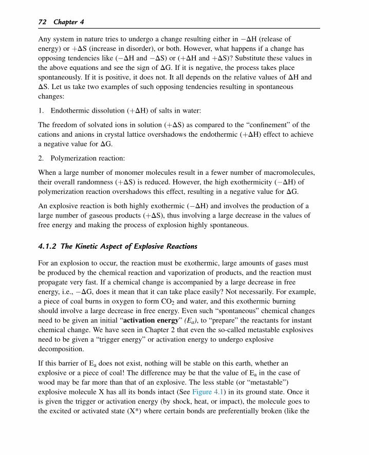
Any system in nature tries to undergo a change resulting either in �DH (release of
energy) or þDS (increase in disorder), or both. However, what happens if a change has
opposing tendencies like (�DH and �DS) or (þDH and þDS)? Substitute these values in
the above equations and see the sign of DG. If it is negative, the process takes place
spontaneously. If it is positive, it does not. It all depends on the relative values of DH and
DS. Let us take two examples of such opposing tendencies resulting in spontaneous
changes:
1. Endothermic dissolution (þDH) of salts in water:
The freedom of solvated ions in solution (þDS) as compared to the “confinement” of the
cations and anions in crystal lattice overshadows the endothermic (þDH) effect to achieve
a negative value for DG.
2. Polymerization reaction:
When a large number of monomer molecules result in a fewer number of macromolecules,
their overall randomness (þDS) is reduced. However, the high exothermicity (�DH) of
polymerization reaction overshadows this effect, resulting in a negative value for DG.
An explosive reaction is both highly exothermic (�DH) and involves the production of a
large number of gaseous products (þDS), thus involving a large decrease in the values of
free energy and making the process of explosion highly spontaneous.
4.1.2 The Kinetic Aspect of Explosive Reactions
For an explosion to occur, the reaction must be exothermic, large amounts of gases must
be produced by the chemical reaction and vaporization of products, and the reaction must
propagate very fast. If a chemical change is accompanied by a large decrease in free
energy, i.e., �DG, does it mean that it can take place easily? Not necessarily. For example,
a piece of coal burns in oxygen to form CO2 and water, and this exothermic burning
should involve a large decrease in free energy. Even such “spontaneous” chemical changes
need to be given an initial “activation energy” (Ea), to “prepare” the reactants for instant
chemical change. We have seen in Chapter 2 that even the so-called metastable explosives
need to be given a “trigger energy” or activation energy to undergo explosive
decomposition.
If this barrier of Ea does not exist, nothing will be stable on this earth, whether an
explosive or a piece of coal! The difference may be that the value of Ea in the case of
wood may be far more than that of an explosive. The less stable (or “metastable”)
explosive molecule X has all its bonds intact (See Figure 4.1) in its ground state. Once it
is given the trigger or activation energy (by shock, heat, or impact), the molecule goes to
the excited or activated state (X*) where certain bonds are preferentially broken (like the
72 Chapter 4
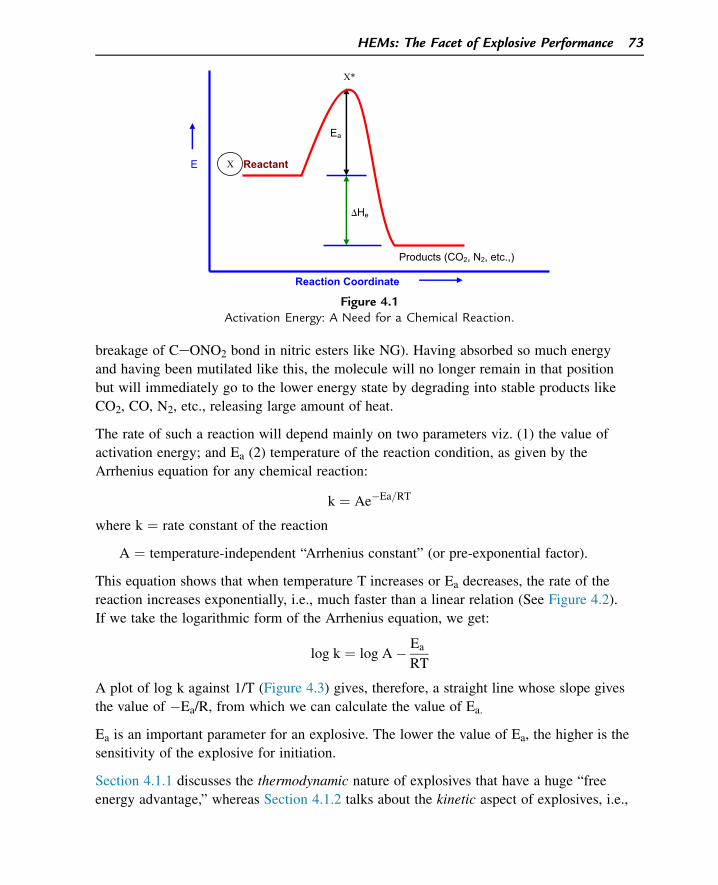
breakage of CeONO2 bond in nitric esters like NG). Having absorbed so much energy
and having been mutilated like this, the molecule will no longer remain in that position
but will immediately go to the lower energy state by degrading into stable products like
CO2, CO, N2, etc., releasing large amount of heat.
The rate of such a reaction will depend mainly on two parameters viz. (1) the value of
activation energy; and Ea (2) temperature of the reaction condition, as given by the
Arrhenius equation for any chemical reaction:
k ¼ Ae�Ea=RT
where k ¼ rate constant of the reaction
A ¼ temperature-independent “Arrhenius constant” (or pre-exponential factor).
This equation shows that when temperature T increases or Ea decreases, the rate of the
reaction increases exponentially, i.e., much faster than a linear relation (See Figure 4.2).
If we take the logarithmic form of the Arrhenius equation, we get:
log k ¼ log A� Ea
RT
A plot of log k against 1/T (Figure 4.3) gives, therefore, a straight line whose slope gives
the value of �Ea/R, from which we can calculate the value of Ea.
Ea is an important parameter for an explosive. The lower the value of Ea, the higher is the
sensitivity of the explosive for initiation.
Section 4.1.1 discusses the thermodynamic nature of explosives that have a huge “free
energy advantage,” whereas Section 4.1.2 talks about the kinetic aspect of explosives, i.e.,
E Reactant
Ea
He
Products (CO2, N2, etc.,)
Reaction Coordinate
X
X*
�
Figure 4.1Activation Energy: A Need for a Chemical Reaction.
HEMs: The Facet of Explosive Performance 73
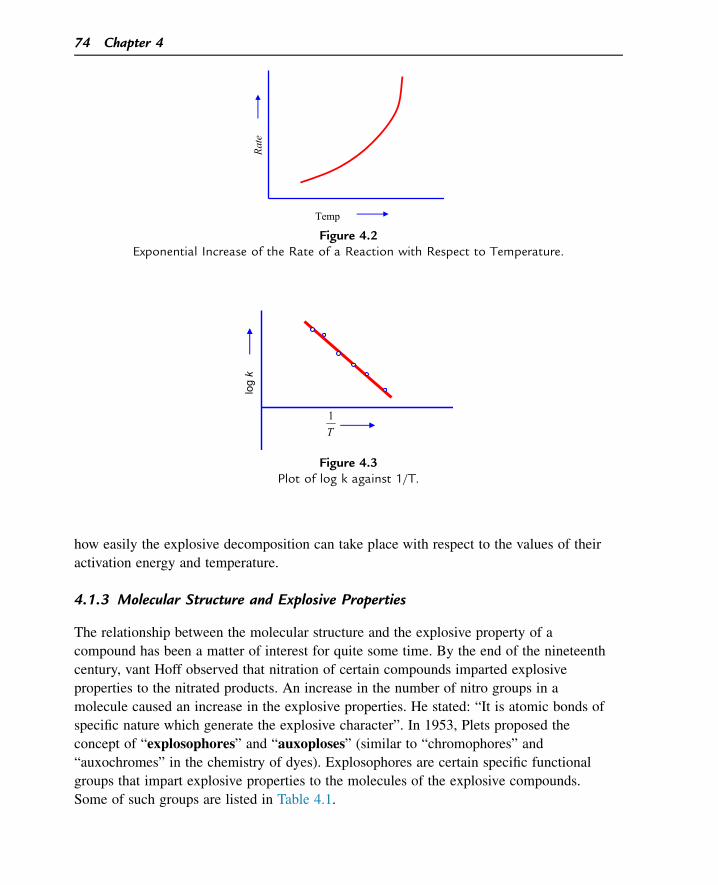
how easily the explosive decomposition can take place with respect to the values of their
activation energy and temperature.
4.1.3 Molecular Structure and Explosive Properties
The relationship between the molecular structure and the explosive property of a
compound has been a matter of interest for quite some time. By the end of the nineteenth
century, vant Hoff observed that nitration of certain compounds imparted explosive
properties to the nitrated products. An increase in the number of nitro groups in a
molecule caused an increase in the explosive properties. He stated: “It is atomic bonds of
specific nature which generate the explosive character”. In 1953, Plets proposed the
concept of “explosophores” and “auxoploses” (similar to “chromophores” and
“auxochromes” in the chemistry of dyes). Explosophores are certain specific functional
groups that impart explosive properties to the molecules of the explosive compounds.
Some of such groups are listed in Table 4.1.
T1
log
k
Figure 4.3Plot of log k against 1/T.
Rate
Temp
Figure 4.2Exponential Increase of the Rate of a Reaction with Respect to Temperature.
74 Chapter 4
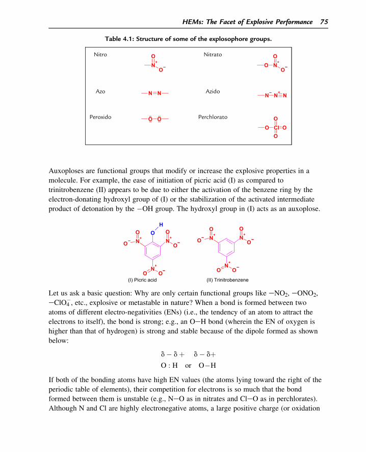
Auxoploses are functional groups that modify or increase the explosive properties in a
molecule. For example, the ease of initiation of picric acid (I) as compared to
trinitrobenzene (II) appears to be due to either the activation of the benzene ring by the
electron-donating hydroxyl group of (I) or the stabilization of the activated intermediate
product of detonation by the �OH group. The hydroxyl group in (I) acts as an auxoplose.
N+
O
ON
+
O
O
N+
OO
OH
N+
O
ON
+
O
O
N+
OO
(I) Picric acid (II) Trinitrobenzene
Let us ask a basic question: Why are only certain functional groups like eNO2, eONO2,
eClO4�, etc., explosive or metastable in nature? When a bond is formed between two
atoms of different electro-negativities (ENs) (i.e., the tendency of an atom to attract the
electrons to itself), the bond is strong; e.g., an OeH bond (wherein the EN of oxygen is
higher than that of hydrogen) is strong and stable because of the dipole formed as shown
below:
d� dþ d� dþO : H or O�H
If both of the bonding atoms have high EN values (the atoms lying toward the right of the
periodic table of elements), their competition for electrons is so much that the bond
formed between them is unstable (e.g., NeO as in nitrates and CleO as in perchlorates).
Although N and Cl are highly electronegative atoms, a large positive charge (or oxidation
Table 4.1: Structure of some of the explosophore groups.
Nitro
N+
O
O Nitrato
N+
O
OO
Azo N N AzidoN N
+N
Peroxido O O Perchlorato
O Cl OO
O
HEMs: The Facet of Explosive Performance 75
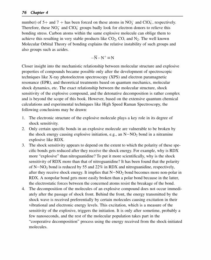
number) of 5þ and 7 þ has been forced on these atoms in NO�3 and ClO4
�, respectively.Therefore, these NO�
3 and ClO4� groups badly look for electron donors to relieve this
bonding stress. Carbon atoms within the same explosive molecule can oblige them to
achieve this resulting in very stable products like CO2, CO, and N2. The well known
Molecular Orbital Theory of bonding explains the relative instability of such groups and
also groups such as azides.
�N�NþhN
Closer insight into the mechanistic relationship between molecular structure and explosive
properties of compounds became possible only after the development of spectroscopic
techniques like X-ray photoelectron spectroscopy (XPS) and electron paramagnetic
resonance (EPR), and theoretical treatments based on quantum mechanics, molecular
shock dynamics, etc. The exact relationship between the molecular structure, shock
sensitivity of the explosive compound, and the detonative decomposition is rather complex
and is beyond the scope of this book. However, based on the extensive quantum chemical
calculations and experimental techniques like High Speed Raman Spectroscopy, the
following conclusions may be drawn:
1. The electronic structure of the explosive molecule plays a key role in its degree of
shock sensitivity.
2. Only certain specific bonds in an explosive molecule are vulnerable to be broken by
the shock energy causing explosive initiation, e.g., an NeNO2 bond in a nitramine
explosive like RDX.
3. The shock sensitivity appears to depend on the extent to which the polarity of these spe-
cific bonds gets reduced after they receive the shock energy. For example, why is RDX
more “explosive” than nitroguanidine? To put it more scientifically, why is the shock
sensitivity of RDX more than that of nitroguanidine? It has been found that the polarity
of NeNO2 bond is reduced by 55 and 22% in RDX and nitroguanidine, respectively,
after they receive shock energy. It implies that NeNO2 bond becomes more non-polar in
RDX. A nonpolar bond gets more easily broken than a polar bond because in the latter,
the electrostatic forces between the concerned atoms resist the breakage of the bond.
4. The decomposition of the molecules of an explosive compound does not occur immedi-
ately after the passage of shock front. Behind the front, the energy transmitted by the
shock wave is received preferentially by certain molecules causing excitation in their
vibrational and electronic energy levels. This excitation, which is a measure of the
sensitivity of the explosive, triggers the initiation. It is only after sometime, probably a
few nanoseconds, and the rest of the molecular population takes part in the
“cooperative decomposition” process using the energy received from the shock-initiated
molecules.
76 Chapter 4
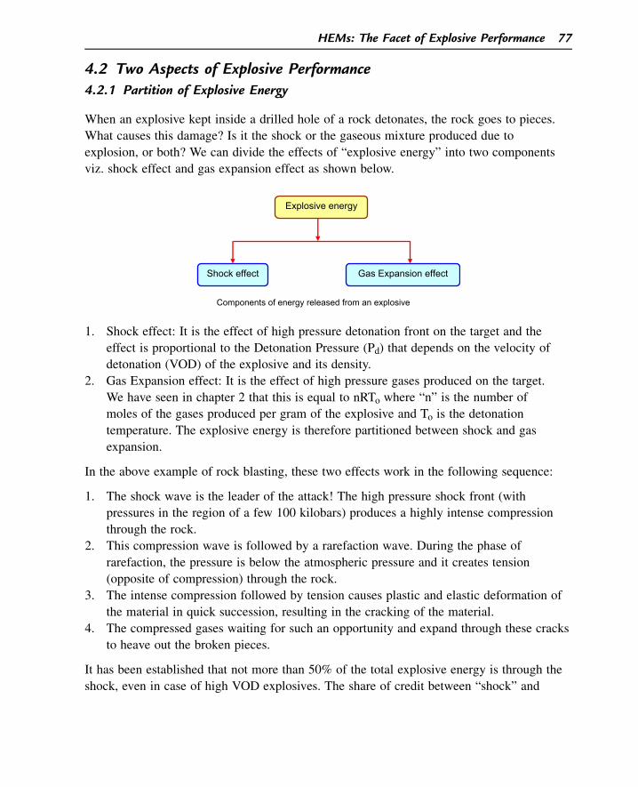
4.2 Two Aspects of Explosive Performance4.2.1 Partition of Explosive Energy
When an explosive kept inside a drilled hole of a rock detonates, the rock goes to pieces.
What causes this damage? Is it the shock or the gaseous mixture produced due to
explosion, or both? We can divide the effects of “explosive energy” into two components
viz. shock effect and gas expansion effect as shown below.
Components of energy released from an explosive
Explosive energy
Shock effect Gas Expansion effect
1. Shock effect: It is the effect of high pressure detonation front on the target and the
effect is proportional to the Detonation Pressure (Pd) that depends on the velocity of
detonation (VOD) of the explosive and its density.
2. Gas Expansion effect: It is the effect of high pressure gases produced on the target.
We have seen in chapter 2 that this is equal to nRTo where “n” is the number of
moles of the gases produced per gram of the explosive and To is the detonation
temperature. The explosive energy is therefore partitioned between shock and gas
expansion.
In the above example of rock blasting, these two effects work in the following sequence:
1. The shock wave is the leader of the attack! The high pressure shock front (with
pressures in the region of a few 100 kilobars) produces a highly intense compression
through the rock.
2. This compression wave is followed by a rarefaction wave. During the phase of
rarefaction, the pressure is below the atmospheric pressure and it creates tension
(opposite of compression) through the rock.
3. The intense compression followed by tension causes plastic and elastic deformation of
the material in quick succession, resulting in the cracking of the material.
4. The compressed gases waiting for such an opportunity and expand through these cracks
to heave out the broken pieces.
It has been established that not more than 50% of the total explosive energy is through the
shock, even in case of high VOD explosives. The share of credit between “shock” and
HEMs: The Facet of Explosive Performance 77
“gas expansion” factors for a damage exercise varies depending on the application, as
below:
1. In certain applications like shaped charge ammunitions (to be discussed shortly), shock
plays a predominant role rather than gas expansion.
2. In certain mining applications like coal mining, gas expansion effect is more important
to heave out large chunks of coal, whereas a high VOD may be disastrous.
3. In many applications, as we have seen in the rock blasting case, both these effects work
hand in hand.
4.2.2 Velocity of Detonation
VOD is the rate of propagation of a detonation in an explosive. It is a major index of the
explosive performance. If the density of an explosive is at its maximum value (i.e.,
theoretical maximum density: theoretical maximum density (TMD)) the detonation
velocity is characteristic of a given explosive. VOD of an explosive, however, depends on
the following major factors:
1. Loading Density (D)
It is defined as the ratio between the weight of the explosive and the explosion volume,
i.e., the space in which the explosive is detonated. If 10 g of RDX is loaded in an enclosed
space of 20 cc, the value of D will be equal to 10 g/20 cc ¼ 0.5 g/cc. The higher the
loading density, the higher will be the VOD for the simple reason that, a higher loading
density ensures a larger quantity of the explosive per unit volume so that larger amount of
evolved energy can sustain the detonation wave.
If D1 and D2 are the values of VOD of an explosive at D1 and D2, the following empirical
relation mostly holds true:
D1 � D2
D1 � D2¼ 3500
Marshall’s formula gives the following relationship between VOD, D, n (number of moles
of gaseous products per gram of the explosive), and Td (detonation temperature).
Dðin m=sÞ ¼ 430 ðn TdÞ1=2 þ 3500 ðD� 1Þ2. Charge diameter
It we detonate a cylindrical column of explosive and measure its VOD, we will find that
the velocity changes if we change the diameter of the column. VOD decreases as the
diameter of the column decreases. This effect is caused by more energy losses to the
peripheral sides of the column. When the diameter is large, the losses are small as
78 Chapter 4
compared to what is produced at the wave front. However, losses become significant as the
column diameter decreases.
Let us take a cylindrical column of an explosive with length L and diameter D. If Ex is the
energy produced per unit volume of the explosive during detonation and Ey is the energy
lost per unit area through its side surface, the percentage of loss of energy through the side
of the column will be:
the energy lost
the energy produced� 100% ¼
�
pDL� Ey
�
pD2L� Ex
4
¼ �100%
¼ 4Ey
DEx� 100% ¼ k
D; ðk ¼ constantÞ
Since Ey and Ex are constants, this percentage loss is found to be inversely proportional to
the column diameter. At lower diameters, the percentage loss of energy increases. Below a
certain diameter that we call as the critical diameter of the explosive, the percentage loss
is so much that the unsupported/unsustained detonation wave dies out. The critical
diameter of an explosive depends on the type of explosive, its density of packing,
inclusion of air bubbles, etc. It can be as small as about 0.5 mm in the case of an initiator
like lead azide and as large as 100 mm in the case of less sensitive, low density
ammonium nitrate.
The concept of “critical diameter” is made use of in the introduction of “detonation trap”
during the manufacture of shock-sensitive NG. These traps whose diameters are less than
the critical diameter of NG do not allow the shock wave to pass through them so that an
accidental detonation in one part of the NG plant is not transmitted to the other parts.
3. Degree of confinement
When the degree of confinement of an explosive increases, it increases its VOD.
4. Strength of Initiation
The higher the strength of initiation of an explosive charge (e.g., by using a powerful
detonator), the VOD of the explosive is higher and vice versa. Weak detonators are used to
initiate industrial explosives to achieve a lower order of VOD. Measurements of VOD
were earlier made by the good old “Dautriche method.” Nowadays, “Pin Oscillography
Technique” and “Streak Camera Techniques” are used for more accurate measurements.
4.2.3 Gas Expansion
Like the shock effect, the expansion work done by the gases is also an index of the energy
of an explosive. As already mentioned in Chapter 2 (Section 2.3.9), this is called as the
HEMs: The Facet of Explosive Performance 79
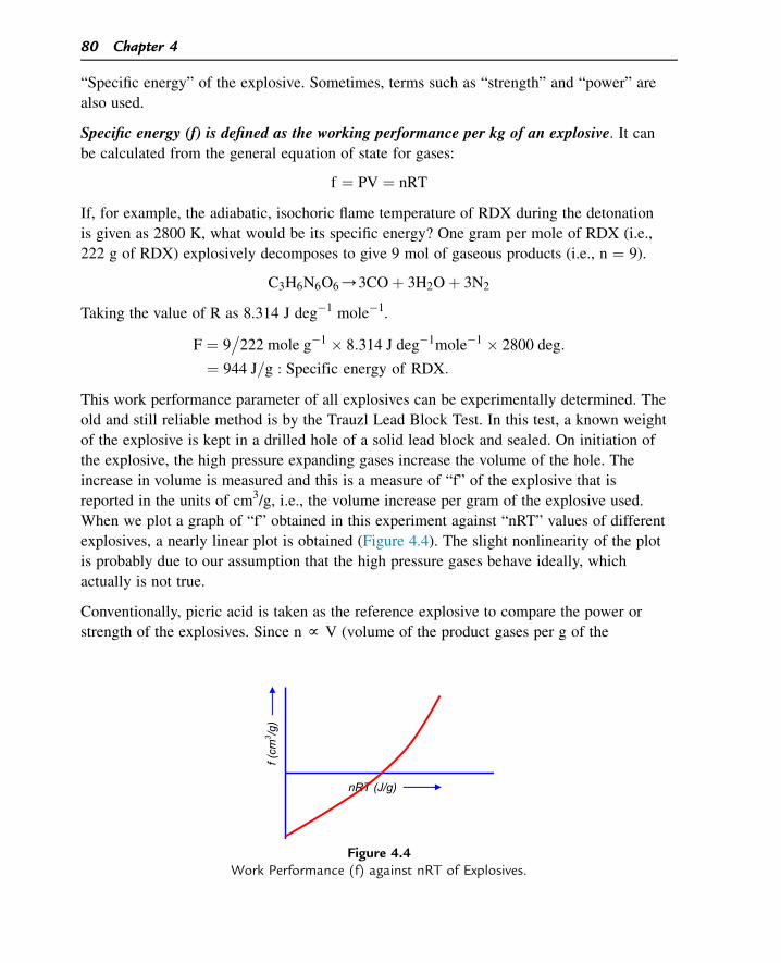
“Specific energy” of the explosive. Sometimes, terms such as “strength” and “power” are
also used.
Specific energy (f) is defined as the working performance per kg of an explosive. It can
be calculated from the general equation of state for gases:
f ¼ PV ¼ nRT
If, for example, the adiabatic, isochoric flame temperature of RDX during the detonation
is given as 2800 K, what would be its specific energy? One gram per mole of RDX (i.e.,
222 g of RDX) explosively decomposes to give 9 mol of gaseous products (i.e., n ¼ 9).
C3H6N6O6/3COþ 3H2Oþ 3N2
Taking the value of R as 8.314 J deg�1 mole�1.
F ¼ 9�
222 mole g�1 � 8:314 J deg�1mole�1 � 2800 deg:
¼ 944 J=g : Specific energy of RDX:
This work performance parameter of all explosives can be experimentally determined. The
old and still reliable method is by the Trauzl Lead Block Test. In this test, a known weight
of the explosive is kept in a drilled hole of a solid lead block and sealed. On initiation of
the explosive, the high pressure expanding gases increase the volume of the hole. The
increase in volume is measured and this is a measure of “f” of the explosive that is
reported in the units of cm3/g, i.e., the volume increase per gram of the explosive used.
When we plot a graph of “f” obtained in this experiment against “nRT” values of different
explosives, a nearly linear plot is obtained (Figure 4.4). The slight nonlinearity of the plot
is probably due to our assumption that the high pressure gases behave ideally, which
actually is not true.
Conventionally, picric acid is taken as the reference explosive to compare the power or
strength of the explosives. Since n f V (volume of the product gases per g of the
f (cm
3 /g)
nRT (J/g)
Figure 4.4Work Performance (f) against nRT of Explosives.
80 Chapter 4
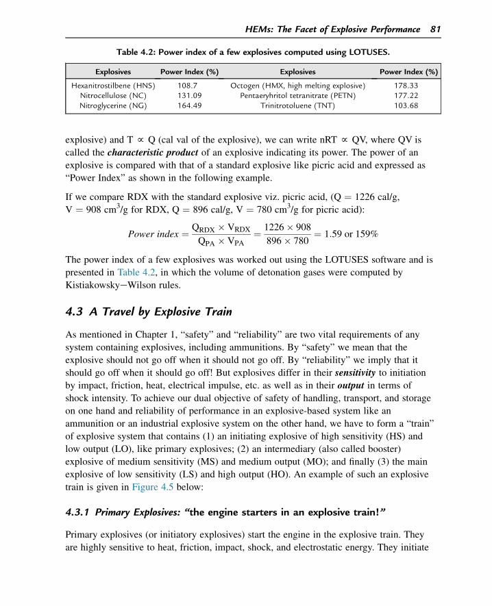
explosive) and T f Q (cal val of the explosive), we can write nRT f QV, where QV is
called the characteristic product of an explosive indicating its power. The power of an
explosive is compared with that of a standard explosive like picric acid and expressed as
“Power Index” as shown in the following example.
If we compare RDX with the standard explosive viz. picric acid, (Q ¼ 1226 cal/g,
V ¼ 908 cm3/g for RDX, Q ¼ 896 cal/g, V ¼ 780 cm3/g for picric acid):
Power index ¼ QRDX � VRDX
QPA � VPA¼ 1226� 908
896� 780¼ 1:59 or 159%
The power index of a few explosives was worked out using the LOTUSES software and is
presented in Table 4.2, in which the volume of detonation gases were computed by
KistiakowskyeWilson rules.
4.3 A Travel by Explosive Train
As mentioned in Chapter 1, “safety” and “reliability” are two vital requirements of any
system containing explosives, including ammunitions. By “safety” we mean that the
explosive should not go off when it should not go off. By “reliability” we imply that it
should go off when it should go off! But explosives differ in their sensitivity to initiation
by impact, friction, heat, electrical impulse, etc. as well as in their output in terms of
shock intensity. To achieve our dual objective of safety of handling, transport, and storage
on one hand and reliability of performance in an explosive-based system like an
ammunition or an industrial explosive system on the other hand, we have to form a “train”
of explosive system that contains (1) an initiating explosive of high sensitivity (HS) and
low output (LO), like primary explosives; (2) an intermediary (also called booster)
explosive of medium sensitivity (MS) and medium output (MO); and finally (3) the main
explosive of low sensitivity (LS) and high output (HO). An example of such an explosive
train is given in Figure 4.5 below:
4.3.1 Primary Explosives: “the engine starters in an explosive train!”
Primary explosives (or initiatory explosives) start the engine in the explosive train. They
are highly sensitive to heat, friction, impact, shock, and electrostatic energy. They initiate
Table 4.2: Power index of a few explosives computed using LOTUSES.
Explosives Power Index (%) Explosives Power Index (%)
Hexanitrostilbene (HNS) 108.7 Octogen (HMX, high melting explosive) 178.33Nitrocellulose (NC) 131.09 Pentaeryhritol tetranitrate (PETN) 177.22Nitroglycerine (NG) 164.49 Trinitrotoluene (TNT) 103.68
HEMs: The Facet of Explosive Performance 81
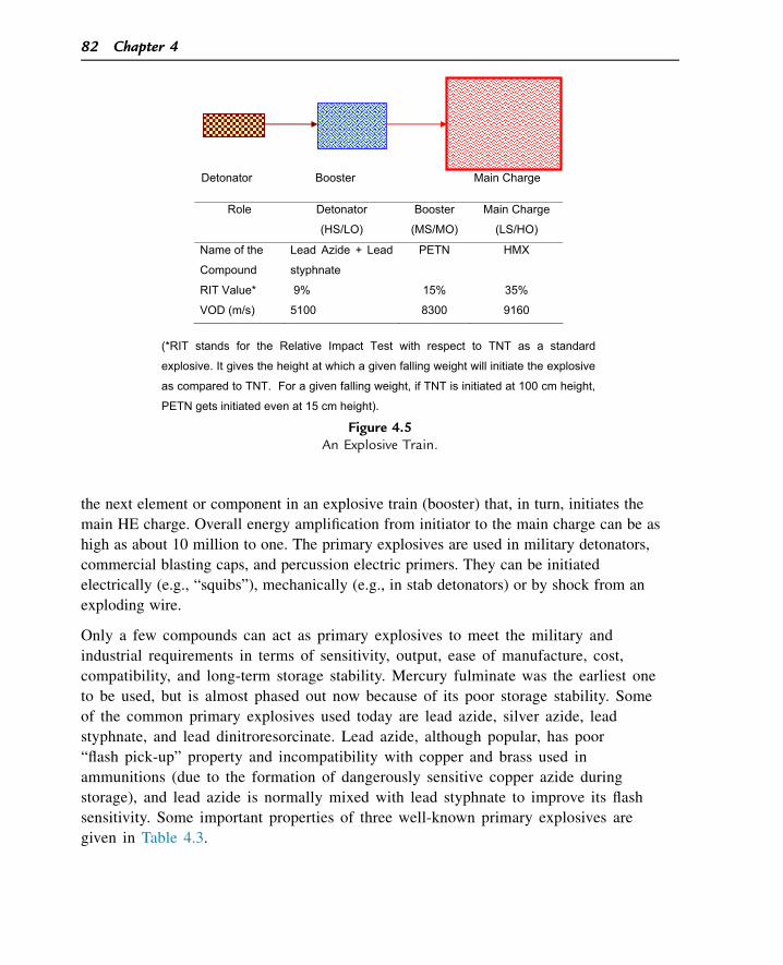
the next element or component in an explosive train (booster) that, in turn, initiates the
main HE charge. Overall energy amplification from initiator to the main charge can be as
high as about 10 million to one. The primary explosives are used in military detonators,
commercial blasting caps, and percussion electric primers. They can be initiated
electrically (e.g., “squibs”), mechanically (e.g., in stab detonators) or by shock from an
exploding wire.
Only a few compounds can act as primary explosives to meet the military and
industrial requirements in terms of sensitivity, output, ease of manufacture, cost,
compatibility, and long-term storage stability. Mercury fulminate was the earliest one
to be used, but is almost phased out now because of its poor storage stability. Some
of the common primary explosives used today are lead azide, silver azide, lead
styphnate, and lead dinitroresorcinate. Lead azide, although popular, has poor
“flash pick-up” property and incompatibility with copper and brass used in
ammunitions (due to the formation of dangerously sensitive copper azide during
storage), and lead azide is normally mixed with lead styphnate to improve its flash
sensitivity. Some important properties of three well-known primary explosives are
given in Table 4.3.
Role Detonator
(HS/LO)
Booster
(MS/MO)
Main Charge
(LS/HO)
Name of the
Compound
Lead Azide + Lead
styphnate
PETN HMX
RIT Value* 9% 15% 35%
VOD (m/s) 5100 8300 9160
(*RIT stands for the Relative Impact Test with respect to TNT as a standard
explosive. It gives the height at which a given falling weight will initiate the explosive
as compared to TNT. For a given falling weight, if TNT is initiated at 100 cm height,
PETN gets initiated even at 15 cm height).
Detonator Booster Main Charge
Figure 4.5An Explosive Train.
82 Chapter 4
4.3.2 Secondary Explosives: “the final operators of the explosive train!”
The secondary explosives are those with low or moderate sensitivity to initiation but with
higher power or output. They include boosters as well as final HE charges. Most of them
come under three categories viz.
1. aliphatic nitrate esters
2. aromatic nitro compounds
3. nitramines (aliphatic/aromatic/heterocyclic)
The details of the properties, preparation, and uses of these explosives will not be
discussed in this section. Only certain salient points will be mentioned.
(1) Aliphatic nitrate esters: They are some of the most powerful explosives with high
values of cal val, and also VOD. However, their stability is less than other classes of
explosives because of the tendency of the CeONO2 bond to get hydrolyzed slowly,
resulting in the formation of acids (HNO3/HNO2) that further catalyzes the decomposition.
[H+]
R-OH + HNO3
H2
N+
O
OOR
Table 4.3: Properties of a few primary explosives.
Property Mercury Fulminate Lead Azide Lead Styphnate
Molecular structureO N
+C
HgO N
+C
PbN
N
N+
N+
N
N N+
O
O
O
O
N+
OO
N+
O
O
Pb2+ H O
2-
. 2
Molecular weight 284.6 291.3 468.3DHf (cal/g) þ225 þ340 �451DHe (cal/g) 355 367 370
Density (g/cc) 4.2 4.8 3.0VOD (m/s) 5400 5300 5200
Relative impact testvalue (%TNT)
5 11 8
Static discharge(max energy fornonignition) (J)
0.07 0.01 0.001
HEMs: The Facet of Explosive Performance 83
The most commonly known explosives of this category are NG, PETN, and NC. The
properties of NG and PETN are given in Table 4.4.
(2) Aromatic nitro compounds: Aromatic nitro compounds are more stable than nitrate
esters. All aromatic molecules are resonance-stabilized and the introduction of an
electron-donating group like methyl groups (“hyperconjugation”) further increases the ring
stability as in the case of TNT, as shown below:
N+
O
O
N+
OO
N+
O
OCH2
H+
N+
O
O
N+
OO
N+
O
OCHH
H
It requires more energy to destabilize such a resonance-stabilized ring, making such
compounds more stable than the aliphatic explosives.
Very high thermal stability of triamino trinitrobenzene (TATB), which melts at about
350 �C, is attributed to an important additional factor viz. extensive network of hydrogen
bonding as shown below:
( denotes intermolecular H-bonding between H atoms of NH2 groups and
O atoms of NO2 groups).
H
H
H
HN
H
N
NN
H
NN
O O
O
OO
OO
O
O
ON
O
N
NN
O
NN
H H
H
HH
H
The important properties of two aromatic nitro compounds viz. TNT and picric acid are
shown in Table 4.4.
(3) Nitramines: While nitric esters represent the OeNO2 explosives and aromatic nitro
compounds represent CeNO2 explosives, nitramines represent NeNO2 explosives. They
can be aliphatic like nitroguanidine, aromatic like “tetryl” (2,4,6-trinitrophenyl methyl
84 Chapter 4
Table 4.4: Properties of selected secondary explosives.
Property NG PETN TNT Picric Acid
Nitro-
Guanidine RDX (Cyclonite) HMX (Octogen) Tetryl
Structure
CC
CH
ONO2H
HH
ONO2H
ONO2
C(CH2ONO2)4 CH3
NO2O2N
NO2
OHNO2O2N
NO2
CNH2 NH
NH
NO2
CH2
NCH2
NCH2
NNO2
NO2O2N
CH2
NCH2
N
CH2NCH2
N NO2
NO2
O2N
NO2
NO2O2N
NO2
NNO2CH3
Mol.weight
227.1 316.1 227.1 229.1 104.1 222.1 296.2 287.1
DHf
(cal/g)�392 �402 �62.5 �225.7 �213.5 76.1 60.4 28.1
OB (%) 3.5 �10.1 �73.9 �45.4 �30.7 �21.6 �21.6 �47.4DHe
(cal/g)1617 1529 1080 1080 769 1375 1357 1140
Density(g/cc)
1.59 1.76 1.65 1.77 1.71 1.82 1.96 1.73
m.p. (�C) 13.2 141.3 80.8 122.5 232 204 275 129.5VOD(m/s)
7600 8400 6900 7350 8200 8750 9100 7570
Impactsensitivity(relative %to TNT)
15 20 100 100 200 35 35 50
Det.pressure(GPa)
e 32 18 26.5 27.3 33.8 39.3 26.2
nitramine), or heterocyclic like RDX (cyclic trimethylene trinitramine) or HMX (cyclic
tetramethylene tetranitramine). Their properties are given in Table 4.4.
Their stability is between that of nitroaromatics and nitric esters, and they are very
powerful. One reason for the higher power or high VOD of these explosives is the
“energetic” (positive heat of formation) nature of NeNO2 bonds. This explains the
positive heat of the formation of RDX, HMX, and tetryl.
4.3.3 The Types of Explosive Trains
Today’s conventional warfare cannot be imagined without the use of explosives and
propellants. An explosive train is a part of any ammunition, whether it is a round fired
from a pistol, large-caliber gun ammunition, hand grenade, or a guided missile. The
explosive train is of two types viz.
1. Igniferous train (or “burning train”)
2. Disruptive train (or “detonative train”)
As mentioned earlier, in both these types of trains, the three components viz “initiator-
booster-main charge” are present in the same order.
In the igniferous train, the transmission is by burning or, more correctly, deflagration,
whereas in disruptive train, the transmission is by the process of detonation. In many
ammunitions, both these mechanisms are operative in sequence.
Figure 4.6 schematically shows a full round of HE ammunition readily loaded in a gun for
action. The full round consists of two parts. The part-1, which is shown as Explosive
Train-1 (ET-1), is an igniferous train. Train ET-1 starts like this:
1. A striker pin strikes the percussion cap at the base of the cartridge and, due to high
impact cum friction, the sensitive pyro composition ignites the moment the striker pin
punctures the cap with force.
Breech A ‘cap’ RDX/TNT Muzzle of the composition (Main explosive) of the gungun (initiator)
Igniter Tetryl(Booster) (Booster)
Gun propellant fuze / detonator(main Propellant charge) (initiator)
ET1 ET2
Figure 4.6Two Types of Explosive Trains Operating in an Ammunition.
86 Chapter 4
2. The initiated cap composition ignites gunpowder in the igniter housing, which burns,
giving out hot particles, and the flame engulfs the entire bulk of large quantity of gun
propellant.
3. The main gun propellant charge weighing a few kilograms burns in a matter of a few
milliseconds, creating high pressure, high temperature gases that propel the projectile
(HE shell) to a great speed.
The entire drama of the eflagration train that results in propulsion of the HE shell takes
only a few milliseconds.
The second drama of “explosive train-2” (ET-2) takes place when the HE shell lands on its
target (naturally, we should not have this drama enacted when it is still inside the barrel!)
with the fuze getting initiated. The sequence of ET-2 will be:
1. The fuse initiates the detonator on striking the target.
2. The shock wave of the detonator is sufficient to initiate the booster pellet
3. The amplified shock wave initiates the main HE charge, wreaking havoc on the target.
4.4 Performance Parameters of Military Explosives
Interestingly, the destructive capabilities of military explosives are varied. The “shattering
effect” of an explosive in a grenade kills or injures personnel or damages sensitive targets
over a given area. The “scabbing effect” cuts out a chunk of armor plate of an enemy’s
tank and throws it right into their cabin. The overpressure of the “blast effect” brings
down structures. The “shaped charge effect” causes deep penetration through heavy
armor plates. The formulation of explosive composition and the overall ammunition design
are so made that the final ammunition achieves one of these specific objectives. We will
see in a little more detail as to how these effects operate.
4.4.1 Fragmentation
The destructive fragmentation effect of an explosive charge on its immediate vicinity is
termed as “brisance.” In a battle scenario, when a brisant explosive shatters a shell or a
grenade, the high velocity fragments create extensive damage on the personnel or objects
in its vicinity. What should be the shape, size, and weight of the fragments depends on the
nature of the target. In case of an antipersonnel grenade, even small fragments will
achieve the purpose of killing or incapacitating the enemy as each fragment acts like a
virtual bullet. On the other hand, if an aircraft is to be destroyed or damaged, the
fragments have to be bigger, each weighing at least about 5 g. The average velocity of
the fragments may vary from as low as 1000 m/s in the case of HE shells to 4000 m/s in
the case of large bombs. The shape, size, and velocity of fragments can be tailored by
HEMs: The Facet of Explosive Performance 87
changing the explosive composition and the ratio of explosive-to-case weight. In a
prefragmented ammunition, the size of the fragments to be formed is predecided by
designing the outer shell accordingly.
What decides the effectiveness or lethality or range of the fragments? The effectiveness of
fragmentation depends on three factors related to the explosive composition filled, viz.:
1. VOD of the explosive
2. Its density
3. Its power (i.e., its specific energy)
Immediately after detonation, the shock front exerts the entire detonation pressure on
the shell. The nature of resulting fragments (their number, size, and velocity) depends on
the detonation pressure, which again depends on factors (1) and (2) above. Just after the
formation of fragments, they are propelled at high velocities by the high pressure gases
produced, and factor (3) above plays the role here.
Kast has come up with the concept of “brisance values.” To achieve high brisance, high
VOD explosive compositions like RDX/TNT are used in fragmenting ammunitions.
Different empirical methods have been reported in literature for comparing the brisance
values of explosive, taking TNT as standard. The “Sand Test” determines the proportion of
standard Ottawa sand crushed by 0.4 g of an explosive using standard sieves. The “Plate
Dent Test” measures the dent produced on a standard steel plate by detonating a
cylindrical column of explosive of known weight. “Upsetting Tests” measure the
fragmentation effect of explosives by detonating a cylindrical column of the explosive kept
over a lead or copper cylinder (keeping standardized buffer plates in between) and
measuring the compression of the metallic cylinder after explosion.
4.4.2 Scabbing
If you want to damage an armor plate of a tank, can you do it without perforating it from
its front side? Sound strange? Yes, it is possible if you exploit the “scabbing” effect of an
explosive (Figure 4.7). It works like this:
The mechanism of scabbing is shown in Figure 4.8. When the explosive in close contact
detonates, the plane shock front travels from left to right (front to rear of the plate) as a
compression wave. The intensity or amplitude of the wave is proportional to its height.
The moment the shock front reaches the rear end, it is “shocked” to see the total
difference in the medium (steel to air) and, therefore, gets reflected back as tension wave
(i.e., “negative shock wave,” which instead of compressing the medium, does the opposite
process of elongating it). At a particular place of the plate, as shown in the figure, the
difference between tension and compression intensifies (at�ac) and exceeds the fracture
88 Chapter 4
strength of the plate. At this point, a large chunk gets detached and is thrown from left to
right, because the effective force here is not compression but tension. Depending on the
quantity and power of the explosive and nature of the armour, the velocity of the scab can
vary and can go up to 130 m/s, killing the tank crew instantly.
As scabbing is purely a shock phenomenon, the HE composition used in HESH
ammunition must produce a high detonation pressure. Compositions based on RDX and
HMX are mostly used for this purpose.
4.4.3 Shaped Charge Penetration
In 1888, C. E. Munroe discovered that when a conical cavity is created in a column of
explosive charge, on detonation, it could penetrate a solid object. Further research in this
Compression wave
Tension wave
ac
at
Detaches here
Figure 4.8The Mechanism of Scabbing.
(a) (b) (c)
TankCrew
HESH Warhead
ArmourPlate
Figure 4.7The Scabbing of an Armor Plate. (a) A High Explosive Squash Head (HESH) Ammunition Hitsthe Armor Plate. (b) The High Explosive inside the Warhead is “Spread” on the Plate, i.e., inComplete Contact with the Plate. It Goes Off. (c) A Large Chunk of the Armor Plate on Its
Rear Side is Detached and Thrown Right into the Crew Cabin, Killing or Injuring the Crew andDamaging the Equipment.
HEMs: The Facet of Explosive Performance 89
line established the ideal conditions for maximum penetration of hard targets like steel
using such “shaped charges” or ‘hollow charges.’ The ideal conditions would be:
1. Introduce a concentric conical cavity at the end of a cylindrical column of an explosive
charge.
2. Line the cavity with a malleable, metal-like copper
3. Keep a certain minimum “stand-off” distance between the base of the conical cavity
and the steel plate (or target) as shown in Figure 4.9:
Once the detonation occurs, the entire explosive energy is concentrated to collapse the
metallic liner, which is transformed into a high velocity jet. About 20% of the metal liner
gets transformed into a jet, which has a velocity gradient from its tip (up to 9000 m/s) to
tail (about 1000 m/s). A shaped charge, if properly designed, can penetrate steel plates
eight times as thick as the diameter of the charge.
The mechanism of jet formation and penetration is interesting:
1. When the HE charge detonates, the shock wave passes over the liner, and the liner is
accelerated at some small angle to the interface between the explosive and liner.
2. Since the liner velocity has been found to be directly proportional to the C/M
(C: Charge weight of explosive over the liner, M ¼ Weight of the metallic liner at a
given point), it is observed that at the apex of the cone (“A” in Figure 4.9), the liner
velocity is the highest. The liner velocity goes on decreasing as we go down the cone
toward its base.
3. We, therefore, see that the jet comes out first from the apex and the rest of the liner is
“squeezed out” following the “apex jet,” but at lower and lower speeds. The remaining
material, which is the bulk of the liner, forms a heavy slug that follows the jet at a
much lower velocity, as shown below (Figure 4.10). In fact, after some point it becomes
a discontinuous jet.
However, why do we need a stand-off distance? The stand-off distance (usually expressed
as charge diameters) is essential for the proper development of a metallic jet until the tip
A
HE Charge Steel plate
Detonator Copper linerStand-off distance
�
Figure 4.9A Shaped Charge.
90 Chapter 4
achieves tremendous kinetic energy. The stand-off distance has to be optimal. If it is too
short, we are not giving enough time and distance for the formation of high velocity jet. If
it is too long, the jet breaks up and each particle hits further and further away from the
center of the target. Maximum penetration has been found when the stand-off is about five
times the cone diameter, with the cone angle around 42�. Optimum liner thickness is about
3% of the cone diameter for copper.
The penetration capacity of the liner is directly proportional to the kinetic energy of
the jet and inversely proportional to the area of cross-section of penetration. As
regards the explosive filled in a shaped charge, its VOD and density have a bearing on
its performance. This is because of the fact that the main driving force behind the
penetration is the detonation pressure (Pd), which is equal to rD2/4, r, and D being
the density and VOD of the explosive, respectively. Most of the shaped charges use
RDX-based compositions. In exceptional cases, where still higher performance is
needed, the much costlier b-HMX is used, as it has higher density and VOD than
RDX.
The main applications of the “shaped charge effect” are their use in High Explosive Anti-
Tank (HEAT) shells for the penetration of tank armor, in “cutting charges” used for the
demolition of concrete and steel structures like bridges, and in a flexible, linear-shaped
charge that consists of a flexible lead alloy with a L-shaped cross section that contains
desensitized explosive composition for versatile applications.
4.4.4 Blast
Blast is defined as a phenomenon caused by rapid expansion of high temperature, high
pressure gases as a result of an explosion. World War II operations proved that much
greater damage can be done to installations by blast effect from bombs than the
fragmentation effect. In fragmentation, the flying fragments damage only the points of
impact, whereas a blast wave acts like a severe earthquake covering a circular area,
Slug Jet (0.5 to 2 km/s) (1 to 3 km/s) (6 to 10 km/s)
Target
Figure 4.10Jet and Slug Formation from a Shaped Charge.
HEMs: The Facet of Explosive Performance 91
damaging walls, throwing roofs and equipment, and also killing people if they are in the
lethal overpressure region.
When an HE composition in a shell or a bomb undergoes detonation under confinement,
the detonation pressure developed is in the order of a few 105 atm, with the temperature in
the range of 3000e4000�C. The shell material gives way under such drastic conditions
and about half of the explosive energy is used for this shattering and propelling of the
fragments. The rest of the energy (due to high pressure and high temperature gases) is
used for compressing the air around to form the shock wave with a steep plane front (See
Chapter 3). The shock wave spreads spherically outward from the point of detonation and
is followed by the gaseous products behind it. However, after a few milliseconds, the
pressure falls to ambient pressure due to the inertia of moving gases (See Figure 4.11) at
point A.
This is followed by a negative pressure (subatmospheric) phase from point A to point B.
The major damage of the targets experiencing this blast wave (which consists of both the
positive and negative pressure phases) is caused by (1) the peak pressure (represented by
the height of the shock front OP), and (2) the area under the positive pressure phase
(enclosed between OPA). This area is also known as the impulse of the blast wave, which
is the (pressure X time) parameter, or the work done by the overpressure in “pushing” and
damaging the object. In the second phase of negative pressure (area covered between A
and B below X-axis), the gases go in the reverse direction, i.e., toward the point of
detonation. At this time, the target experiences a “pulling” force rather than a push. This
explains the fact that when a detonation occurs at a certain distance outside the window of
P Peak pressure Direction of travelby blast wave
Pre
ssur
e
Positive Phase
Negative phase
A B
O 5 10 15 20 25 30 35 40 45Time (milliseconds)
Point of detonation
Figure 4.11Two Phases of a Blast Wave.
92 Chapter 4
a house, the window panes are shattered and the debris is found outside the house rather
than inside.
Although both the peak pressure (OP) and the impulse (area POA) are destructive, their
damage potential depends on the type of the target. If the target is a light and strong
material (e.g., a window glass pane) a higher peak pressure is needed to break it. If it is a
heavy but weak structure (e.g., a brick wall) a low peak pressure will do, but the impulse
should be relatively higher. While an overpressure of 0.07e0.7 kg/cm2 is enough to break
a window pane, an overpressure of about 6 kg/cm2 is needed to kill a man by fatally
compressing his vital organs.
The blast effects depend on the medium and also the surroundings. While the blast wave
attenuates quickly in an open space (its spherical area increasing in terms of 4pr2), it gets
reinforced in confined spaces like a closed room due to its multiple reflection. While the
blast effect is enhanced in a dense medium (e.g., underwater blast), it is severely
reduced in a rarified atmosphere. For this reason, large quantities of HE composition are
needed for efficient blast effect from the warheads used in anti-aircraft missiles at high
altitudes.
4.4.4.1 Aluminized HE Compositions and Blast
Most of the HE compositions used for creating blast contain a certain percentage of fine
aluminium powder, e.g., Torpex (41% RDX, 41% TNT, 18% Al), Tritonal (80% to 60%
TNT, 20e40% Al), and Minol (40% NH4NO3, 40% TNT, 20% Al). Aluminium plays a
key role in extending the blast effect for a longer duration so that the impulse of the
explosive increases. The addition of aluminium powder produces a longer, flatter P-t curve
in the positive pressure phase of the blast wave as shown in Figure 4.12.
It was found that aluminium does not participate in the initial detonation reaction, but it
adds a large amount of heat to the entire system by subsequently reacting with the
products of detonation, viz. water and carbon dioxide exothermically.
P0
t2
t
P0
t1
t
Pre
ssur
e
Pre
ssur
e
(a) (b)
Figure 4.12P-t Blast Profile of (a) Non-Aluminized Composition and (b) Aluminized Composition.
HEMs: The Facet of Explosive Performance 93
2AlðsÞ þ 3H2OðvÞ/Al2O3ðsÞ þ 3H2 þ 207 k:cal
2AlðSÞ þ 3CO2/Al2O3ðSÞ þ 3COþ 177 k:cal
The above reactions do not alter the total number of moles of gas in the system (Al and
Al2O3 being solids), but at the same time, significantly increase the flame temperature due
to the evolution of large quantities of the heat. This increased temperature increases the
pressure of the gaseous products so that the positive pressure region gets further extended
and the overall impulse (i.e., the area under the P-t curve) is enhanced.
However, increasing aluminium beyond a certain percentage is not preferable due to two
reasons:
1. Firstly, excess aluminium may further react with CO to form carbon, thereby decreasing
the total number of moles of gaseous products, resulting in the lowering of nRT values.
2AlðSÞ þ 3CO/Al2O3ðSÞ þ 3CðSÞ
2. Subsequent mixing of the unreacted or partly reacted gases with atmospheric oxygen
may produce a delayed secondary explosion.
The percentage of aluminium in an HE composition should, therefore, be optimized
accordingly.
4.5 Industrial Explosives4.5.1 Introduction
For more than 350 years, explosives have been employed to mine ores and minerals.
World annual consumption of industrial explosives is at least 5 � 106 tons, a major part of
which is ammonium nitrateefuel oil (ANFO).
During the first 250 years of this period, only black powder was known and used, but
fundamental changes occurred in the 1860s (the invention of dynamite and blasting cap by
Alfred Nobel), 1950s (ANFO), and 1980s (emulsions). The search continues for less
expensive products and safer techniques for production and field-use in mines, quarries,
roads, tunnels, and dam construction. At the same time, the introduction of new products
is restrained by the cost of existing investments and by safety and environmental
regulations.
“Industrial Explosives” is too big a field to be discussed in detail in this section. The
intention of the author is to sketch out only the salient concepts concerning them with
respect to their chemistry vis-a-vis their application.
Gunpowder was, perhaps, the first civil explosive used. As far back as 1627, it was used
for mining in Slovakia. Then came a less messy explosive in the form of dynamite
94 Chapter 4

containing 75% NG, invented by Alfred Nobel (Figure 4.13). Other developments that
followed included low-freezing NG explosives, Permitted Explosives (usable in gassy coal
mines), detonators, and detonating cords. A new development took place in 1930s with the
development of much safer, less sensitive and more cost-effective “blasting agents,”
mostly based on ammonium nitrate (AN). Blasting agents include “AN-Fuel Oil (ANFO),”
non-cap sensitive “slurry explosives,” and “emulsion explosives,” which are of fairly recent
origin.
The industrial explosives have played a great role in the development of the economy
of many countries. The most common applications include mining, civil
engineering, agriculture, petroleum engineering (seismic prospecting and perforation of
oil wells), etc.
4.5.2 Requirements of Industrial Explosives
The sharp differences between the requirements of industrial explosives and that of
military explosives have been mentioned in Chapter 1. The major requirements of
industrial explosives can be summarized as under:
1. Safety of processing, handling, transport, and storage
2. Safety during their performance (for example, when used in gassy coal mines, they
should not ignite marsh gas, resulting in a disaster).
3. Cost-effectiveness that calls for inexpensive starting materials.
Figure 4.13Alfred B. Nobel.
HEMs: The Facet of Explosive Performance 95
4. Adequate strength
5. Tailorability of power
6. Good fume characteristics: no toxic gases should be evolved
7. Reasonable storage life
8. Good water resistance
The explosives chemist who has to formulate the composition for an industrial explosive
for a specific use has a rather complex task ahead of him. He will have to choose a
composition that will be the best compromise of the above requirements. He will have to
use a variety of ingredients for this purpose. For example, he may have to use:
• an antacid like chalk to ensure better storage life of explosives based on NG, which un-
dergoes acid-catalyzed decomposition during storage.
• Freezing point depressants like nitroglycol (NG freezes at 13�C and the solid NG is
dangerously sensitive to impact and friction) to be added to NG-based explosives.
• Gelatinizers like NC to avoid exudation of NG.
• Flame temperature depressants like sodium chloride so that they can be safely used in
gassy coal mines. Methane present in coal mines easily forms a dangerous explosive
mixture with air. If the mining explosive results in a flame having a high temperature,
longer duration, and higher length, it will ignite this explosive mixture, causing a
disaster. NaCl ensures that a part of the explosive energy of the mining explosive is
spent to dissociate it, thereby decreasing the temperature and duration of the flame and
avoiding such a disaster.
• Fine powder of metals, particularly aluminium (but not in gassy coal mines where a
methaneeair mixture can be set off by the high temperature Al2O3 particles formed
during the explosion) as a fuel-sensitizer.
Simultaneously, he has to ensure that all these ingredients are compatible with each other.
He has to take care that the OB of the composition is almost zero. Highly positive OB and
highly negative OB compositions will result in the evolution of toxic gases viz. oxides of
nitrogen and carbon monoxide, respectively, and this will not be acceptable. Lastly, there
should be no compromise in safety, storage stability, and the cost.
4.5.3 Industrial High Explosives
Today the industrial explosives can be broadly classified as “High Explosives” and
“Blasting Agents.” While the main ingredient in the former category is NG, the blasting
agents mainly use AN in different types of formulations. NG-based explosives are quite
powerful and more water-resistant than blasting agents, but the problem of their sensitivity,
cost, and the limited extent of their tailorability have made them a thing of the past,
paving the way for safer, cheaper, and more easily tailorable blasting agents.
96 Chapter 4
The NG-based industrial explosives can be categorized as below:
1. “Straight dynamites” based on NG and kieselguhr. They are hardly used nowadays
because of their high cost, sensitivity to shock and friction, and poor fuming character-
istics (i.e., evolution of toxic gases during explosion).
2. “Ammonia dynamites” based on the introduction of less sensitive AN in dynamite
composition. This results in lowered VOD and less objectionable shock sensitivity and
fuming characteristics.
3. “Gelatine/Semigelatine explosives”: A small amount of NC is introduced to keep the
explosive in gel/semigel form along with a variety of ingredients. A typical composition
may include NG (base explosive), NC (gelatinizer cum explosive), AN (oxidizer cum
explosive), saw dust (carbonaceous fuel), NaCl (flame temperature depressant), and
chalk (antacid). These types of explosives can be used as “Permitted Explosives” (a
term that is meant for explosives that can be safely used in gassy coal mines).
4.5.4 Blasting Agents
As the requirement of industrial explosives increased by leaps and bounds all over the
world, there arose a necessity to look for NG-free explosives and substitute the NG-based
explosives by AN-containing ones, as AN is the cheapest and safest source of readily
deliverable oxygen for explosives. The concept of blasting agents originated from the
United States. They are mainly AN-based, often free from high explosives like NG and
TNT. They are cap-insensitive (a composition is said to be cap-sensitive if it would go off
when initiated by a No. 8 detonator, which in terms of power, is equivalent to a 2 g
mixture of mercury fulminate and potassium chlorate in the weight proportion of 80:20,
respectively). Being insensitive, the safety regulations for their transport and storage are
much less severe than other explosives in many countries. Some of the popular and widely
used blasting agents are given below:
1. Ammonium Nitrate-Fuel Oil (ANFO)
In 1956, Prof. Cook showed that a 94/6 mixture of AN and a fuel oil based on saturated
hydrocarbons represented an oxygen-balanced composition.
3NH4NO3 þ CH2ðFuel oilÞ
/7H2Oþ CO2 þ 3N2 þ heat
This stoichiometric reaction yields maximum energy (1.025 k cal per gram of the
explosive).
AN exists in five crystalline forms at different temperatures. At ambient temperatures, the
transformation of one form to another changes the crystalline structure and unit cell
volume. It is very hygroscopic and deliquesces at more than 60% relative humidity. This
HEMs: The Facet of Explosive Performance 97
leads to caking of AN into virtually unmanageable “rocks of AN.” This problem has been
solved to a great extent by adding anticaking agents that are coated on AN crystals.
Nowadays, AN is commercially produced as porous “prills” that are free-flowing and can
absorb fuel oil uniformly. ANFO has replaced conventional explosives in open-pit mining.
They can be mixed on-site simply by adding oil to a bag of AN prills. ANFOs, being cap-
insensitive, are usually initiated with an HE booster such as pentolite (PETN/TNT:50/50).
If needed, the sensitivity and energy of ANFO can be increased by the addition of
explosives or powders of aluminium or ferrosilicon.
The principal disadvantage of an ANFO is that it cannot be used under wet conditions.
This led to the development of “slurry explosives.”
2. Slurry Explosives
Also referred as “watergel explosives” or simply “slurries,” this class of explosives
consists of:
1. A saturated aqueous solution of AN. This solution has a suspension of the following
materials:
2. Undissolved nitrates like methyl ammonium nitrate.
3. Metallic fuels like aluminium
4. Organic fuels like glycols
5. “Sensitizers” like TNT or PETN in small amounts
6. A “thickener” like guar gum to impart cohesion or thickness to the entire composite
mixture (like thickener added to soups).
7. Cross-linking agents like borax (which cross-links the �OH groups of guar gum, which
is a polysaccharide. While guar gum swells due to the “unwinding” of its polymeric
structure, cross-linking imparts rigidity to the watergel explosive).
8. Slurries are made sensitive to cap initiation by beating fine air bubbles into them.
However, these have a tendency to coalesce on storage. Sometimes, “microballoons”
(glass or polymeric bubbles with an average diameter of about 40 mm) are added to
solve this problem. The air bubbles or microballoons increase the sensitivity of slurries
to initiation due to the adiabatic compression of entrapped air in them that results in
high temperatures and “hot spots.”
Some of the advantages of slurries are:
a. They can be tailor-formulated to suit the energy and sensitivity requirements.
b. Very safe to process, handle and transport
c. Water-compatible (the swelling of guar gun provides an impervious sheath that offers
water resistance to the explosive)
d. Good fuming characteristics
e. Wide choice of densities
98 Chapter 4
f. Directly loadable by priming straight into boreholes.
3. Emulsion Explosives (or “emulsions”)
Emulsions are fairly recent and have superior properties in comparison to ANFO and
slurries. They are based on a “water-in-oil emulsion” system in which small droplets of
saturated AN solution in water are dispersed in a mineral oil phase. This emulsion is
stabilized by the use of surfactants. The advantages of emulsion explosives are:
1. As the fine droplets of oxidizer are in intimate contact with fuel, the explosive reaction
is complete and it confers the advantages of low post-detonation toxic fumes, high
VOD, and being highly waterproof.
2. High density
3. Higher oxygen balance
4. All these factors impart better blasting efficiency to emulsions. Emulsions can be made
pumpable in large boreholes. They can be made in the form of cartridges also to replace
the conventional NG-based explosives.
Apart from mining and quarrying, explosives have many other uses such as avalanche
control, as shown in Figure 4.14.
Explosives in Avalanche Control
Loss of human life and property takes place every year due to snow avalanches. Artificial Trig-gering by firing the slopes is an economical and practical method of avalanche control and isused in various countries. Natural avalanches are triggered when the bonds that hold thesnowpack together break from additional stresses created by factors such as rain, wind, risingtemperatures, and the weight of new snow. It is difficult to predict exactly when or where anavalanche will occur. The most common way that avalanches are artificially triggered is
Figure 4.14An Avalanche being Triggered by an Explosion. Photo Courtesy by Andrew Longstreth, Olympia Fire
Dept., Bonney Lake, USA.
HEMs: The Facet of Explosive Performance 99
through the use of explosives. The objective of avalanche control is to reduce or eliminate thehazard from potentially destructive avalanches. Avalanches may be initiated by detonatinghigh explosives either in or above the snowpack. When such artificial triggers produce ava-lanches, impressions about snow stability can be ascertained, and options for avoiding theconsequent hazards can be formulated. Explosives can be thrown by hand onto target zonesor shot from mortar/artillery guns for more remote delivery of explosive charges.
4.6 Processing of the Compositions
Let us briefly see the principles based on which the explosives are processed. Firstly,
explosives in pure form are hardly used for any application; rather, “HE compositions”
containing one or more explosives and other ingredients are only used. The finished
composition for military applications requires certain mechanical properties like
machineability, and the pure explosives do not possess them. To get an explosive material
of required mechanical property, thermal, and sensitivity characteristics, and also output, a
composition of explosives containing certain ingredients is resorted to. Once this
composition is decided, the technique of processing the composition is decided based on
the physical properties of the ingredients. Three major methods of processing techniques
are mentioned below:
4.6.1 Melt-Casting
TNT is the main explosive base in this technique. The major advantage of TNT is that its
melting point is quite low (w81 �C), whereas its ignition temperature is much higher
(240 �C). Other major explosives do not enjoy this advantage. For example, the melting
point and ignition temperatures of RDX are 204 and 213 �C, respectively, and they are
dangerously close. Unlike TNT, we cannot take the risk of melting RDX for making an
RDX-based composition. Because of such a low melting point, the melting of TNT can be
achieved by steam. High melting explosives like RDX or HMX can be incorporated in the
molten TNT and cast in shells or bombs.
TNT has a very low OB (�74%). It is, therefore, mixed with explosives of higher OB like
RDX (OB ¼ �22%), which also adds to the VOD of the final composition, and with
oxidizers like AN. Apart from the above, in some compositions, Al (to enhance the blast)
and wax (to “phlegmatize,” i.e., to desensitize) are also added. Some typical castables are
given in Table 4.5.
Most of the castable explosives are machineable. Although the melt-casting process is
simple and cheap, the final charges are sometimes prone to cracking, become sensitive,
and cause settling of “heavy” ingredients during solidification, resulting in inhomogeneity
in the composition.
100 Chapter 4
4.6.2 Pressing
The crystalline forms of most of the explosives are such that they cannot be pressed as
such. The pressed pellets may not have the desired cohesion or the crystals may be
sensitive to friction or static electricity development during processing. A lubricant or
phlegmatizer like wax is added to the composition before pressing. The pressing can be of
different types: direct pressing (with or without vacuum), incremental pressing, or isostatic
pressing. During the pressing, the pressure may be in the order of a few tons per square
inch. The temperature and duration of pressing may also vary. It is possible in some cases
to achieve a density of the final pellet almost close (about 99%) to the crystal density or
sometimes called TMD.
4.6.3 Plastic Bonded Explosives (PBX)
PBXs are explosive compositions containing crystalline explosives like RDX or HMX to
which polymeric binders have been added. The procedure of making a PBX is as
follows:
1. The binder polymer is dissolved in a volatile solvent.
2. The explosive crystals/powder are added and mixed to form a slurry.
3. The solvent is evaporated, leaving a coating of the polymeric binder on the explosive
particles.
4. These coated particles are die-pressed or isostatically pressed at high temperatures
(w120�C) and pressures (1e20 kpsi) to get PBX pellets with densities very close to
TMD.
Very high “solid loading” (percentage of solids like RDX in the overall composition) can
be achieved, sometimes as high as about 97% in PBX compositions. A large variety of
polymeric binders can be used like polyurethanes (Estane 5702-F1), polystyrene,
fluoropolymers/copolymers (Viton A, Kel-F-800), nitroacetals/formals (BDNPA-F), etc.
The major requirements of a binder for PBX are: thermal stability, low toxicity,
Table 4.5: Composition and density of typical castable mixtures.
Explosive Composition Density (g/cm3)
Amatol TNT:60, AN:40 1.56Composition B TNT:39, RDX:60, wax: 1 1.713
Comp B2 40% TNT, 60% RDX 1.65Torpex TNT:40.5, Al:18, RDX:40.5, wax: 1 1.81Octol 23.7% TNT, 76.3%HMX 1.809
Cyclotol 23% TNT, 77%RDX 1.743Tritonal 80%TNT, 20%Al 1.72
HEMs: The Facet of Explosive Performance 101
compatibility with explosive ingredients, ease of processing, safe and fast curing
characteristics, and low glass transition temperature.
The main advantages of PBXs are their good mechanical properties, thermal stability, and
safety in processing and handling. Some of the PBXs with their composition and density
are listed in Table 4.6.
Suggested Reading
[1] T.L. Davis, The Chemistry of Powder and Explosives, Wiley, New York, 1956.[2] M.A. Cook, The Science of High Explosives, Chapman & Hall, London, 1958.[3] W. Taylor, Modern Explosives, The Royal Institute of Chemistry, London, 1959.[4] T. Urbanski, Chemistry and Technology of Explosives, vols. 1e4, Pergamon Press, Oxford, New York, 1983.[5] S. Fordham, High Explosives and Propellants, Pergamon Press, Oxford, New York, 1980.[6] C.R. Newhouser, Introduction to Explosives, The National Bomb Data Center, Gaithersburg, USA, 1973.[7] M.A. Cook, The Science of Industrial Explosives, IRECO Chemicals, Salt Lake City, UTAH, USA, 1974.[8] F.A. Lyle, H. Carl, Industrial and Laboratory Nitrations, ACS Symposium Series No.22, Am. Chem. Soc,
Washington, 1976.[9] A. Bailey, S.G. Murray, Explosives, Propellants and Pyrotechnics, Pergamon Press, Oxford, New York,
1988.[10] Blasters Handbook, Du Pont de Nemours, Wilmington, 1980.[11] L.E. Murr (Ed.), Shock Waves for Industrial Applications, Noyes Publications, Park Ridge, New York,
1989.[12] W.R. Tomlinson, Properties of Explosives of Military Interest, Picatinny Arsenal, Dover, N.J, 1971.[13] C.E. Henry Bawn, G. Rotter (Eds.), Science of Explosives (Parts I & II), HMSO Publication, UK, 1956.[14] Service Textbook of Explosives, Min. of Defence Publication, UK, 1972.[15] Military Explosives: Issued by Departments of the Army and Airforce. Washington, DC, 1955.[16] D.H. Liebenberg, et al. (Eds.), Structure and Property of Energetic Materials, Materials Research Society,
Pennsylvania, USA, 1993.[17] P.W. Cooper, Explosives Engineering, VCH Publishers, Inc., USA, 1996.[18] C.E. Gregory, Explosives for Engineers, fourth ed., TransTech Publications, Germany, 1993.[19] E.B. Barnett, Explosives, Van Norstrand Co., New York, 1919.
Table 4.6: Composition and density of a few plastic-bonded explosives.
Name of PBX Empirical Formula Composition
Density
(g/cm3)
PBX-9010 C3.42H6N6O6F0.6354Cl0.212 90% RDX, 10% Kel-F 1.781PBX-9011 C4.406H7.5768N6O6.049 92% RDX, 6% polystyrene, 2% DOP 1.69PBX-9205 C4.406H7.5768N6O6.049 92% RDX, 6% polystyrene, 2% DOP 1.69PBX-9501 C4.575H8.8678N8.112O8.39 95% HMX, 2.5% estane, 2.5%
BDNPF1.841
PBX-9404 C4.42H8.659N8.075O8.47Cl00993P0.033 94% HMX, 3% NC, 3% tris-b-chloroethyl phosphate
1.844
PBX-9407 C3.32H6.238N6O6F0.2377Cl0.158 94% RDX, 6% exon 1.61PBX-9408 C4.49H8.76N8.111O8.44Cl0.0795P0.026 94% HMX, 3.6% DNPA, 2.4% CEF 1.842PBX-9502 C6.27H6.085N6O6F0.3662Cl0.123 95% TATB, 5% kel-F 1.894
102 Chapter 4
Questions
1. What decides the spontaneity of a reaction?
2. Coal gives more heat than TNT. But TNT detonates but not a piece of coal. Why?
3. How does the bond polarity of a functional group in an explosive molecule affect its
sensitivity?
4. What are the two major parts of explosive energy?
5. Which major factors affect the VOD of an explosive?
6. What is meant by “Critical diameter” of an explosive? How is it explained?
7. The detonation temperature of PETN is 3400 K. Calculate its specific energy in J/g.
(Ans: 984 J/g).
8. Why is lead styphnate added to lead azide in detonators?
9. Why are nitroaromatic explosives more stable than the nitric ester explosives?
10. What is the difference between an “igniferous train” and a “disruptive train”?
11. How can you increase the fragmenting power of an explosive?
12. What is the mechanism of scabbing action?
13. How does a conical liner collapse into a jet in an SC?
14. Why is the “stand-off” distance essential in an SC?
15. How does the addition of aluminium increase the blast effect?
16. What are the major requirements of an industrial explosive?
17. What are “Permitted Explosives”? Why is sodium chloride added in Permitted
Explosives?
18. Why is the ratio of AN and fuel oil 94:6 by weight in ANFO explosives?
19. What is the role of (a) guar gum (b) microballoons in slurries?
20. Why are emulsions superior to slurries?
21. What are the three main types of processing explosive compositions?
22. What are the advantages of PBXs?
23. Give two examples for high melting point explosives.
24. What is the relationship between VOD, density and detonation temperature?
25. Define power index of an explosive.
26. Give some examples for “explosophores” and “auoxoploses.”
27. Why is a high VOD explosive dangerous for coal mining application?
28. Who invented the dynamite and blasting cap?
29. Give some examples for castable explosives.
HEMs: The Facet of Explosive Performance 103

This page intentionally left blank
CHAPTER 5
The Propulsive Facet of HEMs:I (Gun Propellants)
5.1 Introduction
Until the nineteenth century, gunpowder was widely used in most types of firearms. The
invention of various smokeless powders led to the ultimate replacement of gunpowder as
a propellant in rifles and guns. It was seen in the first chapter that a breakthrough was
made by Alfred Nobel in the second half of nineteenth century by the invention of
“Smokeless powder,” by gelatinizing NC with NG. It was called “powder” as it was to
replace the messy and inefficient “gunpowder” as a propelling charge. In fact, the
propellants for small arms, mortars, and guns are in the form of “grains” of various
shapes (solid cylinders, monotubular or multitubular or slotted-tubular cylinders, flakes,
etc.) and sizes (as low as 1 mm in length and as high as a few centimeters) depending on
the ammunition in which they are used. We will see shortly why we have to go in for
such different shapes and sizes. As the propellant is meant to convert the chemical energy
packed in it into mechanical/kinetic energy of the projectile, over the years, efforts were
concentrated to develop propellants with higher and higher energy to propel projectiles of
higher and higher masses to longer and longer ranges. At the same time, care was to be
taken to control the flame temperature of the propellant and barrel pressure up to certain
levels to avoid the erosion and bursting of the costly gun barrel, respectively. More than a
century after the invention by Nobel, we have come a long way in the development of
solid gun propellants for small arms, mortars, and guns of various calibers. The
development of a gun propellant for a given ammunition for a given weapon is a joint
exercise by the gun ballistician and the propellant chemist. While the former takes care of
the physics of the drama inside the barrel during the propellant burning and projectile
movement, the latter takes care of the chemistry, particularly the thermochemistry of the
propellant ingredients.
5.2 Gun: the Heat Engine
Figure 5.1 gives a schematic representation of gun propulsion. “W” grams of the
propellant inside the cartridge case (to which the projectile is crimped) would burn in a
matter of a few milliseconds and the high pressure, high temperature gases would propel
the projectile (a shot or a shell) weighing “M” grams, through the muzzle of the barrel.
Demystifying Explosives: Concepts in High Energy Materials. http://dx.doi.org/10.1016/B978-0-12-801576-6.00005-7
Copyright © 2015 Elsevier Inc. All rights reserved. 105
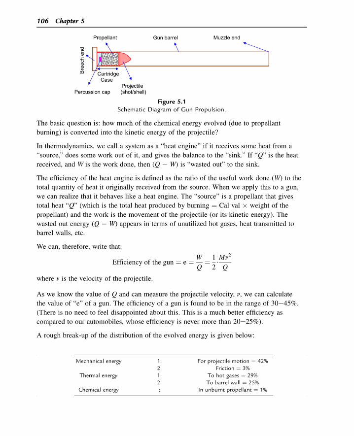
The basic question is: how much of the chemical energy evolved (due to propellant
burning) is converted into the kinetic energy of the projectile?
In thermodynamics, we call a system as a “heat engine” if it receives some heat from a
“source,” does some work out of it, and gives the balance to the “sink.” If “Q” is the heat
received, and W is the work done, then (Q � W) is “wasted out” to the sink.
The efficiency of the heat engine is defined as the ratio of the useful work done (W) to the
total quantity of heat it originally received from the source. When we apply this to a gun,
we can realize that it behaves like a heat engine. The “source” is a propellant that gives
total heat “Q” (which is the total heat produced by burning ¼ Cal val � weight of the
propellant) and the work is the movement of the projectile (or its kinetic energy). The
wasted out energy (Q � W) appears in terms of unutilized hot gases, heat transmitted to
barrel walls, etc.
We can, therefore, write that:
Efficiency of the gun ¼ e ¼ W
Q¼ 1
2$Mn2
Q
where n is the velocity of the projectile.
As we know the value of Q and can measure the projectile velocity, n, we can calculate
the value of “e” of a gun. The efficiency of a gun is found to be in the range of 30e45%.
(There is no need to feel disappointed about this. This is a much better efficiency as
compared to our automobiles, whose efficiency is never more than 20e25%).
A rough break-up of the distribution of the evolved energy is given below:
Gun barrel
Cartridge Case
Projectile Percussion cap (shot/shell)
Bre
ech
end
Propellant Muzzle end
Figure 5.1Schematic Diagram of Gun Propulsion.
Mechanical energy 1. For projectile motion ¼ 42%2. Friction ¼ 3%
Thermal energy 1. To hot gases ¼ 29%2. To barrel wall ¼ 25%
Chemical energy : In unburnt propellant ¼ 1%
106 Chapter 5
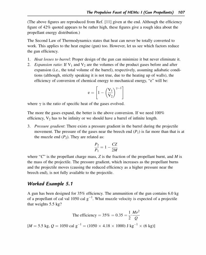
(The above figures are reproduced from Ref. [11] given at the end. Although the efficiency
figure of 42% quoted appears to be rather high, these figures give a rough idea about the
propellant energy distribution.)
The Second Law of Thermodynamics states that heat can never be totally converted to
work. This applies to the heat engine (gun) too. However, let us see which factors reduce
the gun efficiency.
1. Heat losses to barrel: Proper design of the gun can minimize it but never eliminate it.
2. Expansion ratio: If V1 and V2 are the volumes of the product gases before and after
expansion (i.e., the total volume of the barrel), respectively, assuming adiabatic condi-
tions (although, strictly speaking it is not true, due to the heating up of walls), the
efficiency of conversion of chemical energy to mechanical energy, “e” will be:
e ¼"
1��
V1
V2
�g�1#
where g is the ratio of specific heat of the gases evolved.
The more the gases expand, the better is the above conversion. If we need 100%
efficiency, V2 has to be infinity or we should have a barrel of infinite length.
3. Pressure gradient: There exists a pressure gradient in the barrel during the projectile
movement. The pressure of the gases near the breech end (P1) is far more than that is at
the muzzle end (P2). They are related as:
P2
P1¼ 1� CZ
2M
where “C” is the propellant charge mass, Z is the fraction of the propellant burnt, and M is
the mass of the projectile. The pressure gradient, which increases as the propellant burns
and the projectile moves (causing the reduced efficiency as a higher pressure near the
breech end), is not fully available to the projectile.
Worked Example 5.1
A gun has been designed for 35% efficiency. The ammunition of the gun contains 6.0 kg
of a propellant of cal val 1050 cal g�1. What muzzle velocity is expected of a projectile
that weights 5.5 kg?
The efficiency ¼ 35% ¼ 0:35 ¼ 1
2$Mn2
Q
[M ¼ 5.5 kg, Q ¼ 1050 cal g�1 ¼ (1050 � 4.18 � 1000) J kg�1 � (6 kg)]
The Propulsive Facet of HEMs: I (Gun Propellants) 107
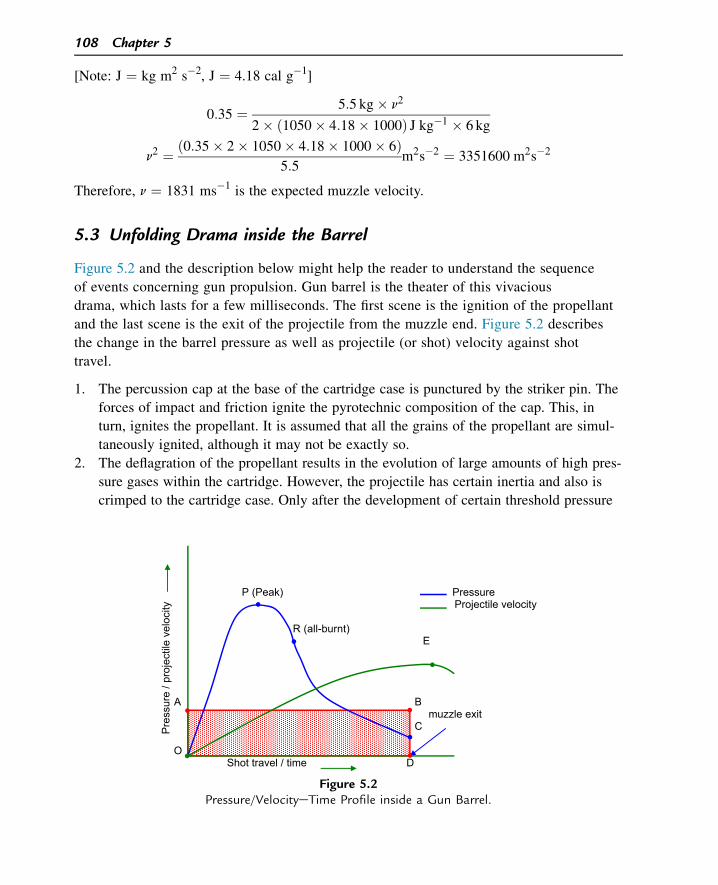
[Note: J ¼ kg m2 s�2, J ¼ 4.18 cal g�1]
0:35 ¼ 5:5 kg� n2
2� ð1050� 4:18� 1000Þ J kg�1 � 6 kg
n2 ¼ ð0:35� 2� 1050� 4:18� 1000� 6Þ5:5
m2s�2 ¼ 3351600 m2s�2
Therefore, n ¼ 1831 ms�1 is the expected muzzle velocity.
5.3 Unfolding Drama inside the Barrel
Figure 5.2 and the description below might help the reader to understand the sequence
of events concerning gun propulsion. Gun barrel is the theater of this vivacious
drama, which lasts for a few milliseconds. The first scene is the ignition of the propellant
and the last scene is the exit of the projectile from the muzzle end. Figure 5.2 describes
the change in the barrel pressure as well as projectile (or shot) velocity against shot
travel.
1. The percussion cap at the base of the cartridge case is punctured by the striker pin. The
forces of impact and friction ignite the pyrotechnic composition of the cap. This, in
turn, ignites the propellant. It is assumed that all the grains of the propellant are simul-
taneously ignited, although it may not be exactly so.
2. The deflagration of the propellant results in the evolution of large amounts of high pres-
sure gases within the cartridge. However, the projectile has certain inertia and also is
crimped to the cartridge case. Only after the development of certain threshold pressure
P (Peak) PressureProjectile velocity
R (all-burnt)E
A Bmuzzle exit
C
OShot travel / time D
Pre
ssur
e / p
roje
ctile
vel
ocity
Figure 5.2Pressure/VelocityeTime Profile inside a Gun Barrel.
108 Chapter 5
(called Shot-start pressure), the projectile detaches itself from the cartridge case and
starts moving along the barrel from point O.
3. We should understand that there are two types of pressure-time variation in the entire
event. Firstly, it is the positive build-up of pressure in the barrel due to the continuous
burning of propellant and evolution of gases, say, þ�
dpdt
�
x
.
Secondly, as the shot moves, the gases have to expand, resulting in the reduction of
pressure with the time, say ��
dpdt
�
y
. The main feature of the in-barrel drama is the
competition between these two types of pressure variations. The net pressure-time,
i.e.,�
dpdt
�
variation in the barrel, depends on which one of these is more dominating.
Initially, from point O to point P, there is a steep pressure rise due to the fact�
dpdt
�
x
>��dp
dt
�
y
It is because, right from the word “go,” the propellant starts burning promptly, whereas the
projectile, due to its inertia, starts its acceleration process rather slowly.
4. At peak pressure, viz point P, they are equally competitive. At this stage, neither the
propellant is fully consumed nor the projectile is out of the barrel.
5. From point P onwards, it is now the turn of the accelerating shot to outshadow the
burning of the propellant so that:��dp
dt
�
y
>
�
dp
dt
�
x
6. At point R, the entire propellant is burnt (called “all burnt” position) and the projectile
has traveled only about one-third of its journey through the barrel.
7. At point C, the shot ultimately escapes from the muzzle but still gets further
accelerated even beyond the muzzle up to point E (see the velocity curve) because
of the muzzle pressure. Muzzle pressure is an important parameter in the design
of the gun system because it gives that “extra kick” to the shot just when it is
shunted out of the barrel! Similarly, the muzzle velocity is a vital parameter in gun
ballistics.
The entire area under OPRCD represents the total work done by the gases to eject the
projectile out. This area can be equated to the area of the rectangle OABD where OD is
the time for the shot travel inside the barrel. OA is referred as the mean pressure of the
barrel.
The Propulsive Facet of HEMs: I (Gun Propellants) 109
5.4 Energetics of Gun Propellant
It was said in Chapter 3 that the “mass burning rate,” or sometimes called mass flow rate
during burning denoted by “ _m”, is a very important parameter.
_m ¼ rAr
Two parameters decide the value of _m (apart from density r). Firstly, it is the
ENERGETICS factor, i.e., the heat output (cal val) of the composition that decides value
of “r”. For example, if we take two identical strands of NG-based (high cal val) propellant
and picrite-based (low cal val) propellant at a given pressure and temperature, the linear
burning rate “r” of former will be much higher than that of the latter. The second factor is
the CONFIGURATION. For a given composition (having a given value of “r”), if we
make two grains of equal weight (same composition), one with larger surface area for
burning (A) than the second, the former gets consumed much faster than the latter. If
one measures the rate of rise of pressure of gases due to the burning of these two grains,
(dp/dt) of the first will be higher than that of the second.
Let us take an interesting example. Picrite-based propellants (sometimes called “cool”
propellants) are known to burn more slowly than NG-based propellants (“hot” propellants)
as mentioned above. However, if we take two cartridge cases, the first containing 1 g of
picrite propellant in the form of 1000 small cylindrical grains and the second containing
1 g of NG propellant in the form of 100 big cylindrical grains, on simultaneous ignition the
former will burn out much earlier than the latter because of the larger surface area available
for burning in case of picrite propellant, although it happens to be a cooler propellant.
We have seen in Chapter 2 that when a propellant burns, only a part of the evolved energy
is diverted for the useful work of gas expansion PDV, and the rest goes only to increase
the internal energy of the gases (DE), i.e.,
Q ¼ DEþ PDV
In fact, PDV should be substituted by PV because in DV (DV ¼ Vproducts � Vreactants) the
volume of the gaseous products is far higher than that of the reactant, i.e., the solid
propellants (about 1 g of the propellant occupying a volume of less than 1 cc evolves
about 1000 cc of the gaseous products). Secondly, at such high pressures as we deal with
in gun propulsion, the gases are no longer ideal in behavior and therefore, we have to
correct the volume occupied by the gases with the co-volume factor “b” because of the
significant value of the volume of molecules themselves at high pressures. The effective
volume occupied by the gases will be (V � b) in place of V. During the deflagration of the
propellant inside a gun barrel, these parameters are related as:
P(V � b) ¼ nRT0. (where T0 is the flame temperature of the propellant)
110 Chapter 5
If we substitute this in the above equation:
Q ¼ DEþ nRT0:
The following points need to be remembered with regard to the energetics of the gun
propellants:
1. nRT0 is the index of useful energy of a gun propellant. It shows how many joules of
energy can be tapped from a burning propellant exclusively to propel a projectile. So, it
has the units of J/g and is called the IMPETUS or FORCE CONSTANT of the propel-
lant. For a given projectile weight and propellant charge mass, the higher the value of
nRT0, the higher will be the muzzle velocity as well as the range of the projectile. The
maximum value of nRT0 achieved in solid gun propellants today is of the order of
1300 J g�1.
2. As T0 is directly proportional to Q, a higher cal val propellant achieves higher impetus.
3. Similarly, if the propellant is based on a compound whose decomposition results in
large values of “n” (number of moles of gaseous products per gram of the propellant)
(low average mol.wt. of the product gases), the nRT0 value goes up.
4. It is quite possible that propellant A has a lower cal val than that of B but has a higher
force constant. The cal val. of NG and RDX are 1750 cal g�1 and 1360 cal g�1, respec-
tively. However, their impetus values are 1318 J g�1 and 1354 J g�1, respectively. This
is because 1 mole of NG evolves 7.25 moles of gaseous products, whereas 1 mole of
RDX evolves 9 moles of the same. The increase in “n” value in case of RDX in
comparison to NG has more than offset its lower cal val figure.
5. Beyond certain flame temperature, the gases start eroding the internal walls of the
costly gun barrel. A limit for T0 is, therefore, a must. Hence, the attempt of a propellant
chemist is to formulate propellant compositions which have higher and higher values of
“n” for an optimized value of T0. Going by the above example, RDX-enriched pro-
pellants are preferred to the hot NG-based propellants.
6. The ratio of specific heats g (¼ Cp/Cv) of the product gases influences the performance
of the gun. We have seen in Section 5.2 that the efficiency of conversion of chemical
energy to mechanical energy “e” is related as:
e ¼"
1��
V1
V2
�g�1#
For a given expansion ratio, viz. (V2/V1) the efficiency increases as the value of g
increases.
For example, if we compare NG and RDX, the molar mean values of g of their
respective products of deflagration can be calculated (using standard values of g
available for CO, CO2, H2O, N2, and O2) as 1.3350 and 1.3773, respectively. If we
The Propulsive Facet of HEMs: I (Gun Propellants) 111
substitute these values in the above equation, say, for an expansion ratio of 20
(i.e., V1/V2 ¼ 1/20), it can be calculated that the values of “e” (efficiency) are
63.3 and 67.7% for NG and RDX, respectively. Thus, apart from the point of view of
“nRT0”, RDX scores over NG in terms of “reduced inefficiency” due to expansion
of gases inside the barrel.
The three parameters of energetics that matter for a gun propellant are, therefore.
1. T0 ¼ flame temperature (with an upper limit).
2. n ¼ the no. of moles of the products per gram of the propellant.
3. g ¼ the ratio of specific heats of the product gases.
Worked Example 5.2
The impetus of picrite (CH4N4O2, mol.wt. ¼ 104.1) is 964 J g�1. Calculate its adiabatic,
isochoric flame temperature, T0 (R ¼ 8.314 J dg�1 mole�1)
The deflagration of picrite is given as below:
CH4N4O2/COþ H2Oþ H2 þ 2N2
ð104:1 gÞ ð5 molesÞ104.1 g evolves 5 mol of gases.
Therefore, 1 g evolves 5/104.1 mol, i.e., n ¼ 5/104.1 mol g�1
i.e., n ¼ 0.048 mole g�1
Impetus (or force constant), F ¼ 964 J g�1
F ¼ nRT0, therefore, T0 ¼ F/nR.
T0 ¼ 964 J g�1
0:048 mole g�1 � 8:314 J dg�1 mole�1¼ 2416 K
(Note: This temperature is much lower than the T0 values of many deflagrating explosives.
That is why picrite-based propellants are also called “cool” propellants.)
5.5 Configuration of Propellant Grains
The pressure-time profile inside the gun chamber and the actual value of the peak pressure
are very important. While the energetics of the propellant (nRT0) matters a lot, the rate of
delivery of this energy also matters equally. Imagine a high energy propellant in a
cartridge case inside the barrel burning as slow as an incense stick for several minutes!
Certainly, the projectile will never reach the end of the tunnel! The propellant grain
112 Chapter 5
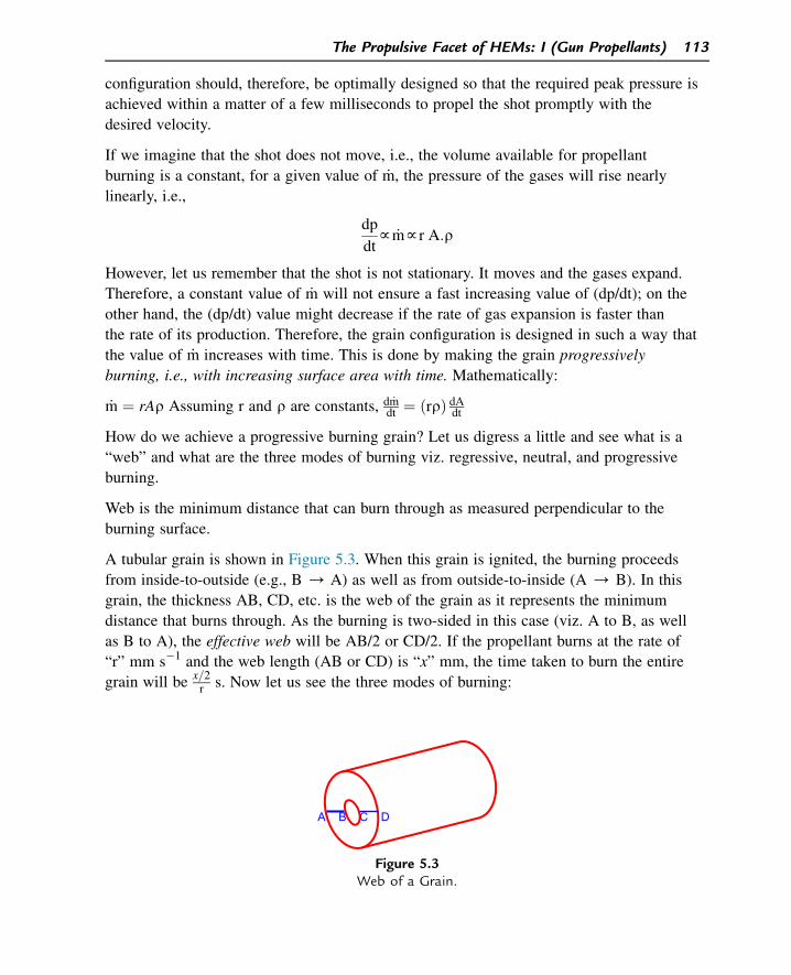
configuration should, therefore, be optimally designed so that the required peak pressure is
achieved within a matter of a few milliseconds to propel the shot promptly with the
desired velocity.
If we imagine that the shot does not move, i.e., the volume available for propellant
burning is a constant, for a given value of _m, the pressure of the gases will rise nearly
linearly, i.e.,
dp
dtf _mfr A:r
However, let us remember that the shot is not stationary. It moves and the gases expand.
Therefore, a constant value of _m will not ensure a fast increasing value of (dp/dt); on the
other hand, the (dp/dt) value might decrease if the rate of gas expansion is faster than
the rate of its production. Therefore, the grain configuration is designed in such a way that
the value of _m increases with time. This is done by making the grain progressively
burning, i.e., with increasing surface area with time. Mathematically:
_m ¼ rAr Assuming r and r are constants, d _mdt ¼ ðrrÞ dAdt
How do we achieve a progressive burning grain? Let us digress a little and see what is a
“web” and what are the three modes of burning viz. regressive, neutral, and progressive
burning.
Web is the minimum distance that can burn through as measured perpendicular to the
burning surface.
A tubular grain is shown in Figure 5.3. When this grain is ignited, the burning proceeds
from inside-to-outside (e.g., B / A) as well as from outside-to-inside (A / B). In this
grain, the thickness AB, CD, etc. is the web of the grain as it represents the minimum
distance that burns through. As the burning is two-sided in this case (viz. A to B, as well
as B to A), the effective web will be AB/2 or CD/2. If the propellant burns at the rate of
“r” mm s�1 and the web length (AB or CD) is “x” mm, the time taken to burn the entire
grain will be x=2r s. Now let us see the three modes of burning:
A B C D
Figure 5.3Web of a Grain.
The Propulsive Facet of HEMs: I (Gun Propellants) 113
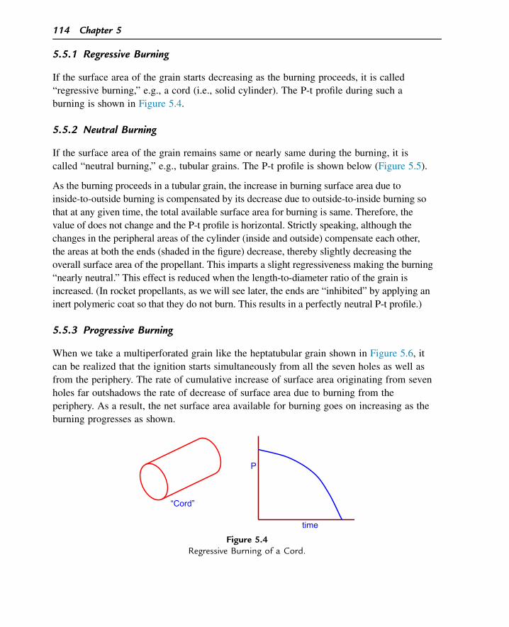
5.5.1 Regressive Burning
If the surface area of the grain starts decreasing as the burning proceeds, it is called
“regressive burning,” e.g., a cord (i.e., solid cylinder). The P-t profile during such a
burning is shown in Figure 5.4.
5.5.2 Neutral Burning
If the surface area of the grain remains same or nearly same during the burning, it is
called “neutral burning,” e.g., tubular grains. The P-t profile is shown below (Figure 5.5).
As the burning proceeds in a tubular grain, the increase in burning surface area due to
inside-to-outside burning is compensated by its decrease due to outside-to-inside burning so
that at any given time, the total available surface area for burning is same. Therefore, the
value of does not change and the P-t profile is horizontal. Strictly speaking, although the
changes in the peripheral areas of the cylinder (inside and outside) compensate each other,
the areas at both the ends (shaded in the figure) decrease, thereby slightly decreasing the
overall surface area of the propellant. This imparts a slight regressiveness making the burning
“nearly neutral.” This effect is reduced when the length-to-diameter ratio of the grain is
increased. (In rocket propellants, as we will see later, the ends are “inhibited” by applying an
inert polymeric coat so that they do not burn. This results in a perfectly neutral P-t profile.)
5.5.3 Progressive Burning
When we take a multiperforated grain like the heptatubular grain shown in Figure 5.6, it
can be realized that the ignition starts simultaneously from all the seven holes as well as
from the periphery. The rate of cumulative increase of surface area originating from seven
holes far outshadows the rate of decrease of surface area due to burning from the
periphery. As a result, the net surface area available for burning goes on increasing as the
burning progresses as shown.
P
time
“Cord”
Figure 5.4Regressive Burning of a Cord.
114 Chapter 5
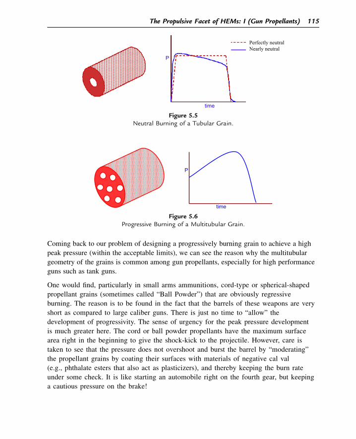
Coming back to our problem of designing a progressively burning grain to achieve a high
peak pressure (within the acceptable limits), we can see the reason why the multitubular
geometry of the grains is common among gun propellants, especially for high performance
guns such as tank guns.
One would find, particularly in small arms ammunitions, cord-type or spherical-shaped
propellant grains (sometimes called “Ball Powder”) that are obviously regressive
burning. The reason is to be found in the fact that the barrels of these weapons are very
short as compared to large caliber guns. There is just no time to “allow” the
development of progressivity. The sense of urgency for the peak pressure development
is much greater here. The cord or ball powder propellants have the maximum surface
area right in the beginning to give the shock-kick to the projectile. However, care is
taken to see that the pressure does not overshoot and burst the barrel by “moderating”
the propellant grains by coating their surfaces with materials of negative cal val
(e.g., phthalate esters that also act as plasticizers), and thereby keeping the burn rate
under some check. It is like starting an automobile right on the fourth gear, but keeping
a cautious pressure on the brake!
Perfectly neutralNearly neutral
P
time
Figure 5.5Neutral Burning of a Tubular Grain.
P
time
Figure 5.6Progressive Burning of a Multitubular Grain.
The Propulsive Facet of HEMs: I (Gun Propellants) 115
The foregoing two sections show that the two factors viz. energetics and grain
configuration jointly decide how quickly the grain can burn, and this “quickness” is
referred as the VIVACITY of the propellant.
5.6 Salient Aspects of Internal Ballistics of Guns
The term “ballistics” means the study of the motion of a projectile. “Internal ballistics” of
gun refers to the branch of applied physics that deals with ballistic properties of
propellants in relation to the motion of the projectile inside a gun barrel. Much of the
theoretical work in this field started as far back as 1870s. In this section, it is not possible
to give a detailed analysis of all the work done in this field, but a few salient points are
mentioned.
1. The equations involved in the internal ballistics of gun establish the relation
between the “gun parameters” (e.g., caliber of the gun, projectile mass, its velocity,
its travel distance at any time “t”, chamber volume, etc.) and “propellant parame-
ters” (e.g., its cal val, force constant, web size and “form function” of the propel-
lant grain, density of the grain, the pressure/temperature/ratio of specific heats/
co-volume of the product gases, and the Equation of State for non-ideal behavior of
the gases) by “Energy equivalence” equations, “Dynamic equations” (related to
projectile movement), burning rate laws for propellants under ballistic conditions,
and “form function.”
2. Burning rate law: In 1885, Vielle established an important relation between the linear
burning rate (r) of a propellant and the pressure (P) under which it burns as:
r ¼ bPa
where a is the pressure exponent and b is the “burning rate coefficient” of the
propellant. This law also applies to both the rocket propellants and gun propellants.
The value of “a” may vary from 0.2 to 0.5 in the case of rocket propellants (actually,
the symbol “n” will be used in the case of rocket propellants), and in case of gun
propellants the value is in the range of 0.8e0.9. This higher exponential variation in
the case of gun propellants is due to high pressures under which a gun propellant
burns (about 4000e6000 kg cm�2) as compared to rocket propellants, whereas P
rarely exceeds 200 kg cm�2.
Higher pressures lead to:
a. faster combustive chemical reactions.
b. Faster heat transmission from the hot gaseous phase to the burning surface
(“condensed phase”).
A linear plot of “log r” against “log P” gives a straight line with “a” as slope and log b as
its intercept on Y-axis.
116 Chapter 5
While the value of a is almost a constant for gun propellants, the value of b is quite
characteristic of a propellant composition. A higher value of b is undesirable for a given
propellant composition as it may cause either uncontrolled burning or the problem of
loadability. Let us consider two propellant compositions “1” and “2”. Assuming their “a”
values w1, their burn rate equations are as given below:
r1 ¼ b1P; r2 ¼ b2P
b1 ¼�r1P
�
b2 ¼�r2P
�
The units of “b” are expressed as cm s�1 (MPa)�1 (where 1MPa w 10.1 kg/cm2). If
b1 >> b2, it means that propellant “1” has a much higher burning rate than propellant
“2” at any given pressure. As a result, for a given grain configuration, its will be so high
that the pressure generated within the barrel will exceed the safe specified limit. On the
other hand, if we want to increase the web size of the propellant (thereby decreasing the
total surface area per grain and hence), the available cartridge case volume may not
accommodate the required charge weight of the propellant, i.e., the propellant becomes
“unloadable.” It should be noted that in a given volume of a cartridge case, the bigger the
individual grains, the lower will be the quantity of the propellant that can be loaded in it.
Today, the value of b of many propellants lies in the range of 0.2e0.3 cm s�1 MPa�1.
Worked Example 5.3
A gun propellant burning at a pressure of 500 MPa has the values of b and a as
0.25 cm s�1 MPa�1 and 0.92, respectively. Calculate the linear burning rate of the
propellant at that pressure.
According to Vielle’s Law:
r ¼ bPa�
b ¼ 0:25 cms�1MPa�1; a ¼ 0:92; P ¼ 500 MPa; r ¼ ?�
log r ¼ log bþ a log P
¼ logð0:25Þ þ 0:92ðlog 500Þ¼ 1:8810
r ¼ A log�
1:8810� ¼ 76:03 cm s�1
3. Equations of State (EOS): The well-known EOS is PV ¼ RT (for 1 mol of an ideal
gas). No gas is ideal, and the non-ideal behavior increases at higher and higher pres-
sures when:
a. the volume of the molecules becomes significant when compared to the volume of
the vessel which they occupy, necessitating a correction for their “co-volume”
(denoted by “b” so that EOS becomes P(V�b) ¼ RT).
The Propulsive Facet of HEMs: I (Gun Propellants) 117
b. due to further closeness between molecules, their intermolecular attractive forces
increase, necessitating a positive correction for the real pressure they exert on the
vessel by an amount ¼ a/V2.
The van der Waals equation thus takes the form:�
Pþ a
V2
�
ðV� bÞ ¼ RT
(“a” and “b” are called van der Waals constants)
It was argued by Abel and Noble that in the range of 2000e3000 K (the deflagration
temperature range of gun propellants), the effects due to intermolecular forces can be
neglected so that the above equation reduces to:
P(V � b) ¼ RT or PV ¼ k þ bP, (k ¼ a constant), which is known as NobleeAbel
equation. A plot of PV against P should give a straight line with a slope equal to “b”.
Mostly, the value of “b” is in the range of 1 ml g�1.
The exclusion of intermolecular forces between molecules at high pressures does not
really present the correct picture. Therefore, the NobleeAbel equation could not become
the exact base for ballistic calculations. Numerous non-ideal gas equations were proposed,
but most of them could not be applied for the gun ballistic conditions. The “truncated
Virial equation,” which takes into account the intermolecular potential (based on the
method proposed by LennardeJones), was an improvement, although it too was not exact.
4. Computer Programs
Although many computer programs are available for performing thermodynamic
computations of different reactions, only a few specific programs exist for the burning of
gun propellants like TRAN 72 and BLAKE, which take into account of the non-ideality of
gases more quantitatively to arrive at realistic solutions. They perform thermodynamic
calculations including equilibrium concentration of gaseous products at constant, as well
as varying pressures and temperatures under gun ballistic conditions. For more
information, the readers may see the references given at the end of the chapter.
5. Closed Vessel (CV) Test
Gun firing using large amounts of gun propellants for the purpose of initial evaluation or
for quality control during production is a costly affair. A CV apparatus is used for such
purposes. The principle of a CV test is to fire a propellant of known loading density (i.e., a
known mass of the propellant in a fixed space available inside the CV) using an “igniter”
like gun powder and measuring the change of pressure (P) as well as (dP/dt) with respect
to time. CV is a rudimentary laboratory tool that may not exactly replace a gun because
(1) it does not exactly simulate the condition of gas expansion due to projectile movement
118 Chapter 5
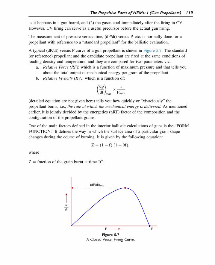
as it happens in a gun barrel, and (2) the gases cool immediately after the firing in CV.
However, CV firing can serve as a useful precursor before the actual gun firing.
The measurement of pressure versus time, (dP/dt) versus P, etc. is normally done for a
propellant with reference to a “standard propellant” for the ballistic evaluation.
A typical (dP/dt) versus P curve of a gun propellant is shown in Figure 5.7. The standard
(or reference) propellant and the candidate propellant are fired at the same conditions of
loading density and temperature, and they are compared for two parameters viz.
a. Relative Force (RF): which is a function of maximum pressure and that tells you
about the total output of mechanical energy per gram of the propellant.
b. Relative Vivacity (RV): which is a function of:�
dp
dt
�
max
� 1
Pmax
(detailed equation are not given here) tells you how quickly or “vivaciously” the
propellant burns, i.e., the rate at which the mechanical energy is delivered. As mentioned
earlier, it is jointly decided by the energetics (nRT) factor of the composition and the
configuration of the propellant grains.
One of the main factors defined in the interior ballistic calculations of guns is the “FORM
FUNCTION.” It defines the way in which the surface area of a particular grain shape
changes during the course of burning. It is given by the following equation:
Z ¼ ð1� fÞ ð1þ qfÞ;where
Z ¼ fraction of the grain burnt at time “t”.
(dP/dt)max
P P
dtdP
Figure 5.7A Closed Vessel Firing Curve.
The Propulsive Facet of HEMs: I (Gun Propellants) 119
f ¼ fraction remaining at the time of least thickness.
q ¼ form function.
The value of q is zero for neutral burning geometries (e.g., Long tubes). It is positive and
negative for grains that burn regressively (e.g., cords) and progressively (e.g., multitubular
grains), respectively.
5.7 The Chemistry of Gun Propellant Formulations
The propellant chemist has rather a hard job on his/her hands. He/she is required to
develop a propellant with suitable composition, shape, and size to meet the complex needs
of an ammunition. It is not only the energy requirements he/she has to bother about. The
propellant he/she develops should meet the following requirements in general:
1. Energy delivery requirement: In terms of cal val/nRT0/loadability.
2. Manufacturing characteristics: In terms of cost and availability of raw materials/
hazards of manufacture/propellant viscosity and flowability/environmental consider-
ations, reproducibility, etc.
3. Storage requirements: Effect of (low and high) temperature cycling on performance,
mechanical properties, moisture absorption, exudation of plasticizer, etc.
4. Compatibility requirements: Compatibility with the process equipments and processing
personnel (mainly toxicity) and compatibility among ingredients.
5. Mechanical properties requirements: To have good compression strength and percentage
of compression at high (gun barrel) pressures. (If the grains crack under pressure before
ignition, the extra surface area exposed will boost the barrel pressure to disastrous
levels.) To withstand high acceleration forces and rough handling.
6. Reliability of performance: To ensure lot-to-lot reproducibility characteristics in terms
of burning rate, RF, and RV.
7. System requirements: Smokeless and flashless exhaust gases, ignition and combustion
stability, absence of pressure waves, absence of deflagration-to-detonation (DDT) char-
acteristics, minimum sensitivity to heat, high velocity fragments, and other stimuli.
Very often, the achievement of all the above requirements at the same time may be quite
difficult and the propellant composition is chosen as the best compromise of all these
factors.
A gun propellant consists of the following main classes of ingredients:
1. “Energetic binder”: To ‘bind” all the ingredients into a cohesive grain and also impart
energy (NC is the most commonly used binder).
2. Plasticizers: Energetic plasticizer like NG and fuel type plasticizers like phthalate
esters.
120 Chapter 5
3. Stabilizers: e.g., Carbamite, diphenylamine, etc.
4. Coolants: e.g., Dinitrotoluene.
5. Flash suppressants: e.g., potassium salts.
Today, we can classify gun propellants into four categories:
1. Single base propellants: Based mainly on NC. They also generally contain plasticizer,
stabilizer, and flash suppressants (used in small arms and low caliber guns). Grain shape
may be of cord or tubular, depending on ballistic requirements. Made by “solvent”
extrusion method.
2. Double base propellants: (used mainly in low caliber guns and mortars).
Based on NC þ NG gel matrix (more energetic than single base) þ plasticizer þ stabilizer
þ coolantdgrain shape may be of tubular or multitubular or tiny spheres called “ball
powder,” flakes in case of propellant used for mortars. They are made by solvent as well
as solventless extrusion methods.
3. Triple base propellants: Based on the (NC þ NG þ picrite) system containing similar
additives as aboved“cooler” (low flame temperature) and more “gassy” due to the
presence of nitrogen-rich picrite (nitroguanidine)dused in large caliber guns. They are
made by the solvent extrusion method.
4. Low vulnerability ammunition (LOVA) propellants: Propellant compositions excluding
NC have been developed to impart insensitivity to accidental initiation of the propellant
by high velocity projectile impact. They are based on inert polymeric binders like cellu-
lose acetate in the matrix in which fine, desensitized RDX is dispersed to impart more
impetus to the propellant. Some typical compositions and their performance parameters
are given in Table 5.1.
(Abbreviation of the names of chemicals: DNT ¼ Dinitrotoluene, DBP ¼ Dibutyl
phthalate, DPA ¼ Diphenyl amine, DOP ¼ Dioctyl phthalate, NC ¼ Nitrocellulose,
NG ¼ Nitroglycerine.)
Except “ball powders,” i.e., ball-shaped propellants, most of the gun propellants are made
by the extrusion technique. The major steps involved in the processing of a typical single
base propellant are given below:
1. Dehydration: Water-wet NC is dehydrated by mixing with alcohol and squeezing out in
a press (Dry NC is highly sensitive to impact and heat and is, therefore, always stored
with not less than 30% water in it).
2. Incorporation: NC (still containing a little water and alcohol) is mixed in a “sigma
blade” mixer along with other ingredients. A calculated amount of ether and alcohol
mixture is added at the time of this mixing to partly “gelatinize” NC. During the
semi-gelatinization, the fibrous nature of the NC is partly destroyed. (The fibrous
The Propulsive Facet of HEMs: I (Gun Propellants) 121
NC burns too fast. In a finished propellant grain, this may result in the development
of very high pressures and burst the gun barrel. If fully gelatinized, the burn rate
will be too low to create the necessary peak pressure and P-t profile for imparting
the required muzzle velocity to the shot. That is why we go in for
semi-gelatinization.)
3. Extrusion: The mixed dough is extruded through a die-pin assembly to get long strands
of required cross-section.
4. Cutting: The long strands are cut into grains of required length and dried well to bring
down the solvent content (Volatile Matter%) as per specification.
5. Graphiting: The dried grains are given a fine coating of graphite with the following
purposes:
a. Graphiting ensures free flow of the grains and, therefore, better loadability in
cartridge cases.
b. Graphite, being a good conductor, helps in avoiding static electricity hazards that
might accidentally initiate the propellant ignition.
c. It helps in insulating the grain from ingress of moisture during storage.
6. Sieving: The grains are sieved to eliminate any odd-shaped or broken grains and fine
powder.
Table 5.1: Composition and energetics of some typical gun propellants.
Parameter Single Base
Double
Base Triple Base Nitramine Base
Composition (%) NC(13.15%N)
90 NC(12.2%N)
49.5 NC(13.1%N)
20.8 NC(13.15%N)
30
DNT 7.5 NG 47.0 NG 20.6 RDX 60DBP 1.5 Carbamite 3.5 Picrite 55.0 DNT 5DPA
(þ0.5 partK2SO4)
1.0 Carbamite 3.6 DOP 4
Carbamite(þ1 part K2SO4)
1
Cal val (cal g�1) 850 1175 880 1000Flame temp (K) 2850 3600 2793 3236
Average molecularwt (mole�1)
23.8 25.6 22.4 22.4
Force constant(J g�1)
987 1168 1037 1190
Linear burn ratecoeff., b1
(cm s�1 MPa�1)
0.10 0.25 0.13 0.15
Note: The linear burn rate coefficient b is denoted as b1 when it is assumed that a ¼ 1 in Vielle’s equation.
122 Chapter 5
7. Blending: Each batch is evaluated ballistically (e.g., by CV) and different batches are
blended accordingly to realize the expected ballistics.
Three major factors that are to be taken care of during a propellant manufacture are:
a. Quality Control: Strict quality control needs to be exercised right from raw material
inspection to blending of finished batches. For example, if NC has a lower “nitrogen
content” (less percentage of nitrato groups in the chain), it will result in lower energy
of the propellant. If its “ether-alcohol solubility” is more than specified, it might
cause excessive gelatinization and reduction in burning rate of the finished propellant.
Each and every process parameter is to be scrupulously respected to ensure the
quality and reproducibility of performance of the finished propellant. (Sometimes,
propellant making is described as an art. There is some truth in this statement,
although each aspect or step of propellant processing has a scientific explanation. It
is like giving the job of baking a cake to an experienced baker and a novice simulta-
neously. Although both of them know the finer details of the recipe and start with the
same type of raw materials, the veteran baker comes out with a better cake! In the
propellant processing, too, the experience plays a key role. For example, a veteran
propellant processing technician knows by the look and texture of the dough whether
the correct level of gelatinization has been reached or not.)
b. Safety: A baker can take a chance, but not a propellant technician! The latter
deals with sensitive energetic materials and flammable solvents during the propel-
lant processing. There can be no compromise with safety regulations during pro-
pellant manufacture like excellent housekeeping, flame-proof fittings, wearing of
cotton clothes and conducting shoes (to dissipate any static electric charges),
maintenance of the required relative humidity (min 60%), use of personnel pro-
tective equipments, strict adherence to the process schedule, etc. There have been
a large number of instances when even a minor lapse in safety precautions
resulted in disastrous accidents.
c. Packing: Proper packing of the propellant (both internal and external) as per the
regulation not only ensures safety during transport and storage, but also ensures a
long shelf-life of the propellant.
5.7.1 Role of Ingredients
The role played by some major ingredients used in gun propellants is described below:
1. Nitrocellulose (NC)
NC was synthesized more than a century back. Still, it rules the roost in many propellant
compositions. That is because, its parent compound, viz. cellulose is a wonderful material.
Cellulose is the natural polymer found in plants. It is a long polymeric carbohydrate chain
The Propulsive Facet of HEMs: I (Gun Propellants) 123
interconnected by b-glucopyranose units. The molecular structures of cellulose and NC are
shown below:
nCellulose
Nitration (HNO3 /H2SO4 / H2O)
n
Nitrocellulose (partly rd32 nitrated)
OCH2OH
HH
H
OH
OH
HHOO
CH2OH
HH
H
OH
OH
HHO O
OCH2ONO2
HH
H
OH
ONO2
HHOO
CH2ONO2
HH
H
OH
ONO2
HHO O
Each glycosydyl unit of the cellulose structure has three hydroxyl groups, viz. one primary
OH (i.e., CH2OH) group and two secondary OH (i.e., eCHOH) groups. Each unit of NC
can be represented by the empirical formula (C6H7O2(OH)3). The square bracket shown in
the figure covers two such units.
The cellulose polymer is a long chain with a large number of repeating units (n) and hence
has a high molecular weight. The actual molecular weight of cellulose depends on the
source and type of cotton linters or wood pulp from which it is prepared. Its molecular
weight may vary from a few 100 thousands to a few millions. When cellulose is purified
and nitrated using HNO3/H2SO4/H2O mixture (called “nitrating mixture”), we get NC as
shown above. Some of the interesting points in this connection are:
a. Depending on the end use of NC, the specification of properties of NC is varied.
Some of the important properties of NC are (1) Nitrogen content, (2) Molecular
weight (which determines the viscosity of NC when dissolved in a solvent like
acetone or when gelatinized in a mixture of solvents like ether þ alcohol), (3)
average fiber length. The required properties depend on the source of cellulose and
the nitrating conditions such as temperature, pressure, duration, and the actual
composition of the nitrating mixture, as well as further processing of nitrated cellu-
lose. For example, for the NC required for double base rocket propellants, we need
NC with lower viscosity (and therefore molecular weight) as compared to NC for
124 Chapter 5
gun propellants. To achieve this, NC is pressure-boiled to breakdown the molecular
chain of NC to a certain level.
b. It is very difficult to nitrate all the eOH groups of cellulose to get fully nitrated NC
(which theoretically corresponds to 14.14% N content).
c. Nitrogen content (% N): By varying the nitrating mixture composition, the ratio of
the nitrating mixture to cellulose, nitration temperature and nitration duration, NC
with varying % N can be obtained. If x is the average number of nitrated groups
(out of three in a unit) and y is the % N, we can show that and:
y ¼ 1400:8x
162:14þ 45xx ¼ 162:14y
1400:8� 45y
Worked Example 5.4
Only 75% of the hydroxyl groups of cellulose could be nitrated during the manufacture of
a batch of NC. Calculate the percentage nitrogen of NC obtained.
Every glycosydyl unit of cellulose contains three hydroxyl groups. The number of eONO2
groups in the final product (NC) corresponds to 75% of three OH groups, i.e., ¼ 2.25
groups.
The above formula:
y ¼ 1400:8x
162:14þ ð45xÞ ¼1400:8� 2:25
162:14þ ð45� 2:25Þ¼ 11:97% is the nitrogen content
An increase in % N (i.e., percentage of NO3 groups) increases the energy (cal val) of NC.
For example, the cal vals of NC samples with 12.60, 13.15, and 14.00% nitrogen contents
are 3.91, 4.25, and 4.77 kJ g�1, respectively. The percent N value of NC is, therefore, an
important property, as that will be a decisive factor for the energetics and, to some extent,
the mechanical properties of the propellants that are NC-based. The use of NC varies
depending on its % N as shown below.
% N Use12.2e13.15 Propellants
11e12 Blasting gelatine8e11.5 Commercial use
(celluloids, lacquers,etc.)
The Propulsive Facet of HEMs: I (Gun Propellants) 125
d. Viscosity: Cellulose has a fibrous texture. After its nitration, NC still retains the fibrous
texture although X-ray diffraction study shows a crystalline structure for NC of higher
%N. The main characteristic of NC is its polymeric chain length, i.e., its molecular
weight. During nitration of cellulose, the number of repeating units in the molecule
gets reduced from 1000 to 3000 units (depending on the source and initial chemical
treatment of cellulose) to somewhere between 400 and 700 units because of the molec-
ular chain degradation owing to nitration conditions. The average molecular weight of
NC plays an important role in propellant chemistry in terms of (a) processibilitydfor
example, a high mol.wt. NC gives a highly viscous dough that cannot be extruded; and
(b) mechanical properties: a lower molecular weight NC reduces the mechanical prop-
erties like tensile strength and compression strength of the finished propellant grain. It
is, therefore, essential to have NC of optimum molecular weight.
The viscosity of standard solutions of NC (e.g., a given weight of NC dissolved in a
solvent consisting a mixture of acetone and water in the ratio of 93:7 by volume,
respectively) is indicative of its average molecular weight. Hence, the determination of
viscosity of NC is an important quality-control aspect in a propellant manufacture. As
mentioned above, the viscosity of NC can be brought down during its manufacture by
“pressure-boiling” of its aqueous suspension in mild alkaline medium, and the process
parameters need to be optimized and established to get NC of desired viscosity.
e. “Blended NC”: During the manufacture of NC for small arms and gun propellants,
there is a dual requirement. The NC sample to be used in propellant composition
should have certain specified N% (let us say, Nx), and certain specified ether-alcohol
solubility (let us say, Sx). While Nx ensures the correct energy level of the finished
propellant, Sx ensures that NC will be gelatinized to the required extent. However,
NC manufactured by nitration (called “straight cut NC”) may not meet this dual
need. Two different batches of straight cut NC (say having the values of N1, S1; and
N2, S2, respectively) are blended in such a proportion that the blended NC meets the
requirement of Nx and Sx.
2. Plasticizers/gelatinizers
The term “gelatinizer” is not to be confused with the term “plasticizer.” Plasticizer
facilitates the mobility of the molecules in relation to one another. Even inactive and inert
compounds like Vaseline, which is a mixture of hydrocarbons, act as plasticizer. When
they are added, say, during polymer processing, it increases the workability/flexibility/
plasticity of the polymer apart from providing better low temperature properties like lower
Glass Transition temperature to the final polymer product. Gelatinizer, on the other hand,
interacts with the polymer by an electron donor/acceptor mechanism. Some compounds
play both these roles as NG does with NC.
126 Chapter 5
The fibrous texture of NC is mainly due to the interchain adhesion due to hydrogen bonding
between the adjacent layers. In the case of NG, its molecules are small enough to penetrate
through the interstitial space between NC layers and undo such interchain adhesion with the
help of their own polar eONO2 groups. This helps in slidability of NC layers, thus effacing
the fibrous texture of NC. What results is a gel matrix of NC/NG that becomes workable
and safe, too. Thus, NG is a gelatinizer and also performs the function of a plasticizer.
Two major types of plasticizers are used in propellant manufacture viz. (1) energetic
plasticizers (mainly NG) and (2) non-energetic/low energy plasticizers. Solvents like
acetone and alcohol (containing polar groups of C]O and eOH, respectively) are
volatizable gelatinizers, i.e., they can be easily removed almost completely by the
end of propellant processing. Phthalate esters (e.g., diethyl, diamyl phthalates) are
nonvolatile plasticizers and are permanently present in the propellant composition.
Phthalate esters also serve as fuels and have some stabilizing effect by
absorbing any products of decomposition like oxides of nitrogen during the propellant
storage.
3. Stabilizers
Being nitric esters, NC and NG have limited stability as the ROeNO2 bond is susceptible
to hydrolytic cleavage, resulting in the evolution of oxides of nitrogen over a period of time.
R�O�NO2 /H2OðmoistureÞ
Higher storage temp:R�OHþ HNO3
2HNO3/2NO2 þ H2Oþ ðOÞAlthough the concentration of NO2 evolved may be very small, it is sufficient to catalyze
further decomposition of NC or NG, resulting in what is called the “autocatalysis” of the
propellant decomposition. This is undesirable in terms of safety as well as the ballistic
shelf-life (since loss of ONO2 groups means loss of energy).
To arrest this possibility of the autocatalysis, some stabilizing compounds are added so
that they can absorb in situ such oxides of nitrogen in their molecular structure and
prevent the catalyzed decomposition of NC and NG. Some well-known examples of the
stabilizers used in the propellant industry are given below:
a. Diphenyl amine (DPA)
DPA is a base and it absorbs the acidic oxides of nitrogen to form the nitro/nitroso
derivative, thereby protecting NC from their attack. (DPA is used only in single base
propellants. It is not used in NG-based compositions as it is too strong a base and initiates
the base-catalyzed hydrolysis of NG.)
The Propulsive Facet of HEMs: I (Gun Propellants) 127
NO2 / H2O
DPA N-nitroso, 2 nitro DPA
N
H
N
N+
OO
NO
b. 2-nitro diphenyl amine (2NDPA)
As shown below, the nitro group of 2NDPA, due to its electron withdrawing tendency,
reduces the basicity of DPA. NG-containing compositions, therefore, use 2NDPA as
stabilizer.
N
HN
O O
..
..
..:..:
c. Sym-diethyl diphenyl urea (also called carbamite or ethyl centralite)
H5C2
N C
C2H5
N
O
It is an excellent stabilizer, which readily absorbs any evolved oxides of nitrogen. It also
acts as a plasticizer and a moderant.
4. Antacids (e.g., chalk)
NC-containing propellants are likely to have “acidity problems” originating from the
manufacture of NC, wherein strong nitrating mixture is used. Chalk (CaCO3) in small
quantities is added to neutralize this acidity and prevent any acid-catalyzed decomposition
of NC and NG in propellant composition during storage.
5. Coolants
Compounds with low cal val are added to propellant to bring down the flame temperature
of propellants in certain compositions. These compounds endothermically decompose and
thereby, reduce the overall heat output during propellant deflagration. Dinitrotoluene
(DNT) and phthalate esters act as coolants.
128 Chapter 5
6. Flash suppressants
NC, the major ingredient in most of the gun propellants, has a negative OB. All other
ingredients, with the exception of NG, have a still higher negative OB, with the result that
the propellant composition, as a whole, always has a negative OB. As a result, when the
propellant deflagrates within the barrel, the product gases that come out are severely
underoxidized and abound in CO and to a fair extent, H2. The deflagration of NC (with
12.75% N) can be written as:
2C12H15O20N5/6CO2 þ 18COþ 10H2Oþ 5H2 þ 5N2 þ Heat
(C12H15O20N5 refers to the empirical formula of one repeating unit, i.e., with two
glycosydyl units in NC molecule, where five out of six hydroxyl groups of its cellulose
precursor have been replaced by eONO2 groups.)
When large quantities of hot and oxygen-hungry gases of CO and H2 rush out of the
muzzle, they are greeted by the atmospheric oxygen and immediately get oxidized to CO2
and H2O, respectively. As these reactions are highly exothermic, the heat of their
combustion appears as a big flash. (The Lower Explosive Limits of CO and H2 in air are
12.5 and 4%, respectively).
Such a big muzzle flash in a battle scenario is undesirable as it reveals the position of the
gunner to the enemy, particularly in the nights. To suppress the muzzle flash, salts of
potassium such as K2SO4, KNO3, and K3AlF6 are added in the propellant composition.
Studies have revealed that at the high deflagration temperatures of the propellant, these
salts decompose to form the free radicals of the potassium metal that, being highly
reactive, immediately combine with oxygen and thereby inhibit the chain reactions that are
responsible for the oxidation of CO and H2. At the muzzle condition, the preference of
atmospheric oxygen goes to higher reactive potassium free radicals rather than CO and H2.
One disadvantage of these inorganic salts is that, although they suppress the flash, they
cause some amount of smoke.
It is relevant to make a mention about the role of nitroguanidine (picrite) in triple base
propellants that, for instance, are used in the large caliber gun ammunitions. Picrite has
two advantages viz. (1) it is very rich in nitrogen (53.8%) with the following structure:
NH
NH2 – C – NH – NO2
Large amounts of nitrogen in the product gases dilute the CO and H2 and reduce the
chances of their oxidation and generation of flash (2) It is a “cool” ingredient
(cal val ¼ 769 cal g�1) and hence, the flame temperature of the propellant is low. This
significantly reduces the barrel erosion and enhances the barrel life.
The Propulsive Facet of HEMs: I (Gun Propellants) 129
(A question might arise in the light of above description: Why then, do we not go in for a
propellant composition that has zero or positive OB so that we avert the formation of CO
and H2? Firstly, such a composition will generate more of CO2 and H2O and increase the
average molecular weight of gases, or decrease the value of “n”, thereby decreasing the
impetus of the propellant. Secondly, the complete oxidation being much more exothermic
than in the case of production of underoxidized CO and H2, means that the flame
temperature of the products will rise to unacceptable levels and cause severe barrel
erosion). (3) When the OB of the propellant moves closer to zero, there is a tendency for
the propellant to undergo DDT within the barrel, and this would be disastrous.
7. Surface moderants
It was mentioned in Section 5.5 (under “regressive burning”) that certain propellant grains,
particularly those of regressive burning type, should be surface-coated with substances that
decelerate the initial burning rate of the propellant. Substances such as DNT, phthalate
esters, carbamite, etc. are useful for this role. They should have either a very low or
negative cal val and should be nonvolatile. They are dissolved in ethanol and the solution
is sprayed on the propellant grains in a sweetie-pan. Subsequently, the solvent is removed
by heating, leaving a thin layer of the moderant on the surface of the propellant grains.
8. Wear reducers
A gun barrel is a costly material. It is a product of precision engineering and made of
costly alloy. It has to withstand high pressures and high temperature gases, from round to
round. Beyond certain increase in caliber, the barrel has to be abandoned as the sealing of
product gases, for the generation of required pressure will cease to operate. Efforts are,
therefore, directed to incorporate certain ingredients either in the propellant composition or
in a “wear-reducing liner” that is inserted in the cartridge case before loading the
propellant in it. Some of the anti-wear additives used are TiO2 and talc, which are
naturally occurring magnesium silicate. These compounds are “waxed” to the surface of
the anti-wear liners and when the propellant deflagrates, the wax melts and a fine layer of
TiO2 or talc gets deposited on the inner walls of the barrel. TiO2 and talc, being excellent
heat insulators, are contained by a layer that protects the barrel walls from hot gases to a
great extent. This layer gets removed when the next round of ammunition is fired, but
then, a fresh layer is formed. This cyclic process of layer formation, thermal insulation
from hot gases, layer removal, and layer reformation goes on. Eventually, it increases the
barrel life.
9. Decoppering agents
Many of the gun barrels have “rifled bore,” i.e., they have grooves made inside,
commencing from a certain distance from the muzzle end. These grooves impart a high
spin to the moving projectile because a spin-stabilized projectile has a better aerodynamic
130 Chapter 5
stability during its travel from the muzzle to the target. The fast spinning, high-speed
projectile causes great frictional force between the barrel and the driving band of the
projectile. This results in the deposit of fine copper particles from the driving band into the
grooves, which is undesirable both in terms of safety and ballistics.
To solve this problem, compounds of lead and tin are added in small amounts in the
propellant composition. During the propellant deflagration at high temperatures, these
compounds decompose and form a low melting, high density alloy of lead and tin that
flushes out the fine copper deposits from the grooves.
Suggested Reading
[1] S. Fordham, High Explosives and Propellants, Pergamon Press, Oxford, New York, 1980.[2] K. Fabel, Nitrocellulose, Enka, Stuttgart, 1950.[3] F.D. Miles, Cellulose Nitrate, Oliver & Boyd, London, 1955.[4] J. Quinchon, J. Tranchant, Nitrocelluloses, the Materials and Their Applications in Propellants, Explosives
and Other Industries, Ellis Howard Ltd, Chichester, UK, 1989.[5] R. James, Propellants and Explosives, Noyes Data Corporation, Parkridge, New Jersey, 1974.[6] R. Krier, et al. (Eds.), Interior Ballistics of Guns, Progress in Astronautics and Aeronautics, vol. 66,
AIAA, New York, 1979.[7] C.L. Farrar, D.W. Leeming, Military Ballistics, a Basic Manual, Brassey’s Publishers Ltd, Oxford, 1983.[8] Internal Ballistics, HMSO Publication, UK, 1951.[9] L. Stiefel (Ed.), Gun Propulsion Technology, Progress in Astronautics and Aeronautics, vol. 109, AIAA,
New York, 1988.[10] Service Textbook of Explosives, Ministry of Defence Publication, UK, 1972.[11] E.D. Lowry, Interior Ballistics, Doubleday & Co., Inc, New York, 1968.[12] J. Corner, Theory of Interior Ballistics of Guns, John Wiley & Sons Inc, 1950.[13] W.C. Nelson (Ed.), Selected Topics on Ballistics, Pergamon Press, London, New York, 1959.
Questions
1. What is the order of efficiency of a gun? Which factors affect the efficiency?
2. In an anti-tank gun ammunition, 5.1 kg of a double base propellant whose cal val is
1100 cal g�1 is used. If the projectile of this ammunition weighs 5.2 kg and achieves a
muzzle velocity of 1440 ms�1, calculate the efficiency of the gun. (Ans: 23.0%).
3. Why is muzzle pressure an important parameter?
4. What is meant by “Impetus” or “Force Constant” of a propellant?
5. The average molecular weight of gases produced during the deflagration of a propel-
lant is 21. If the adiabatic isochoric flame temperature reached during the deflagration
is 3000 K, calculate the impetus of the propellant. (Ans: 1188 J g�1).
6. How do the shape and size of a propellant grain influence the rate of pressure rise
inside a gun barrel?
7. The propellant grain configuration in some cases is meant for progressive burning,
whereas in some others for regressive burning. Why?
The Propulsive Facet of HEMs: I (Gun Propellants) 131
8. What is Vielle’s Law? Why should one be concerned about the value of the burning
rate coefficient of a gun propellant?
9. A gun propellant, burning at a pressure of 400 MPa, has the values of b and a as
0.2 cm s�1 MPa�1 and 0.90, respectively. What is its linear burning rate at that
pressure? (Ans: 43.95 cm s�1).
10. What is the purpose of a closed vessel? What do you understand by relative force and
relative vivacity?
11. What are the major requirements of a propellant?
12. Distinguish between single base, double base, triple base, and nitramine base
propellants.
13. Why are certain propellant grains graphited?
14. Why is it said that the propellant making is an art?
15. Nitrogen content of a sample of NC is 13.00%. Calculate what percentage of hydroxyl
groups of its precursor (cellulose) has been nitrated. (Ans: 86.13%).
16. Distinguish between a plasticizer and a gelatinizer. Why do we “semi-gelatinize” NC
while processing propellants for small arms?
17. Why do we blend NC batches before the processing of gun propellants is commenced?
18. Write the possible chemical equation to explain the mechanism of how carbamite
addition stabilizes a propellant composition.
19. In double base propellants, DPA cannot be used as a stabilizer. Why?
20. What is the mechanism of production of muzzle flashes and also their suppression
using inorganic salts in the propellant composition?
21. What are the roles of
(a) Surface moderants, (b) Wear reducers, and (c) Decoppering agents in a propellant
composition?
132 Chapter 5
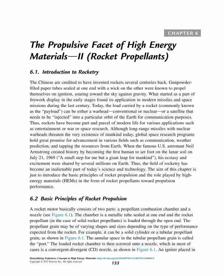
CHAPTER 6
The Propulsive Facet of High EnergyMaterialsdII (Rocket Propellants)
6.1. Introduction to Rocketry
The Chinese are credited to have invented rockets several centuries back. Gunpowder-
filled paper tubes sealed at one end with a wick on the other were known to propel
themselves on ignition, soaring toward the sky against gravity. What started as a part of
firework display in the early stages found its application in modern missiles and space
missions during the last century. Today, the load carried by a rocket (commonly known
as the “payload”) can be either a warheaddconventional or nucleardor a satellite that
needs to be “injected” into a particular orbit of the Earth for communication purposes.
Thus, rockets have become part and parcel of modern life for various applications such
as entertainment or war or space research. Although long-range missiles with nuclear
warheads threaten the very existence of mankind today, global space research programs
hold great promise for advancement in various fields such as communication, weather
prediction, and tapping the resources from Earth. When the famous U.S. astronaut Neil
Armstrong created history by becoming the first human to set foot on the lunar soil on
July 21, 1969 (“A small step for me but a giant leap for mankind”), his ecstasy and
excitement were shared by several millions on Earth. Thus, the field of rocketry has
become an inalienable part of today’s science and technology. The aim of this chapter is
just to introduce the basic principles of rocket propulsion and the role played by high-
energy materials (HEMs) in the form of rocket propellants toward propulsion
performance.
6.2 Basic Principles of Rocket Propulsion
A rocket motor basically consists of two parts: a propellant combustion chamber and a
nozzle (see Figure 6.1). The chamber is a metallic tube sealed at one end and the rocket
propellant (in the case of solid rocket propellants) is loaded through the open end. The
propellant grain may be of varying shapes and sizes depending on the type of performance
expected from the rocket. For example, it can be a solid cylinder or a tubular propellant
grain, as shown in Figure 6.1. The annular space in the tubular propellant grain is called
the “port.” The loaded rocket chamber is then screwed onto a nozzle, which in most of
cases is a convergent-divergent (CD) nozzle, as shown in Figure 6.1. An igniter placed in
Demystifying Explosives: Concepts in High Energy Materials. http://dx.doi.org/10.1016/B978-0-12-801576-6.00006-9
Copyright © 2015 Elsevier Inc. All rights reserved. 133
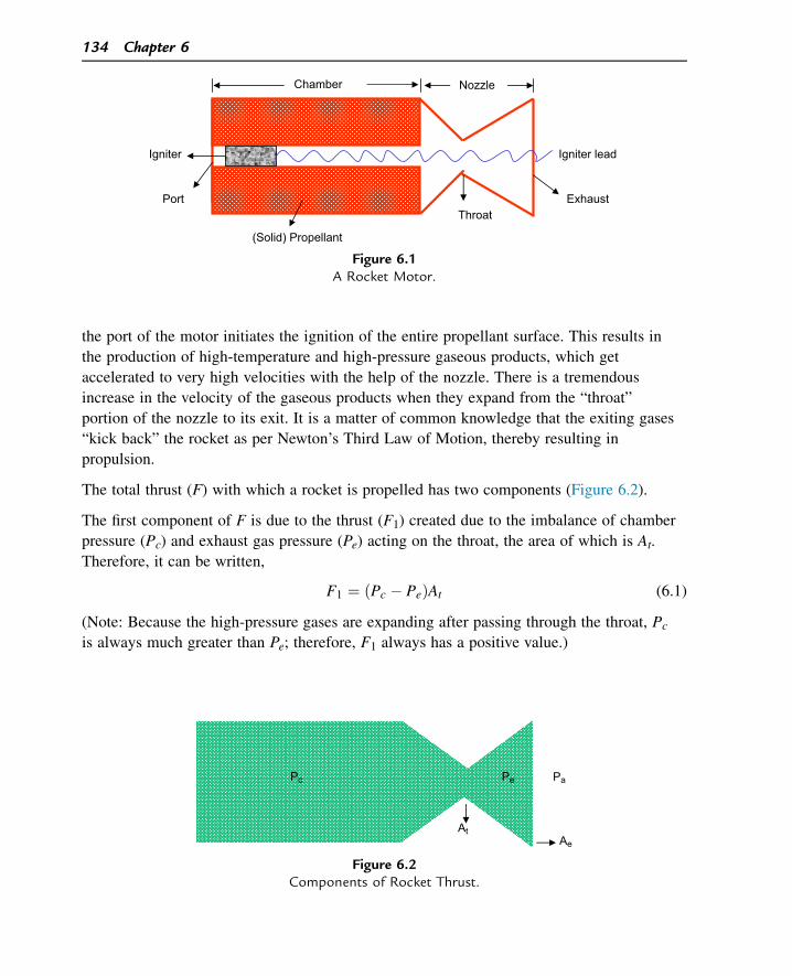
the port of the motor initiates the ignition of the entire propellant surface. This results in
the production of high-temperature and high-pressure gaseous products, which get
accelerated to very high velocities with the help of the nozzle. There is a tremendous
increase in the velocity of the gaseous products when they expand from the “throat”
portion of the nozzle to its exit. It is a matter of common knowledge that the exiting gases
“kick back” the rocket as per Newton’s Third Law of Motion, thereby resulting in
propulsion.
The total thrust (F) with which a rocket is propelled has two components (Figure 6.2).
The first component of F is due to the thrust (F1) created due to the imbalance of chamber
pressure (Pc) and exhaust gas pressure (Pe) acting on the throat, the area of which is At.
Therefore, it can be written,
F1 ¼ ðPc � PeÞAt (6.1)
(Note: Because the high-pressure gases are expanding after passing through the throat, Pc
is always much greater than Pe; therefore, F1 always has a positive value.)
Chamber
Port
Nozzle
(Solid) Propellant
Throat Exhaust
Igniter lead Igniter
Figure 6.1A Rocket Motor.
PaPePc
Ae
At
Figure 6.2Components of Rocket Thrust.
134 Chapter 6
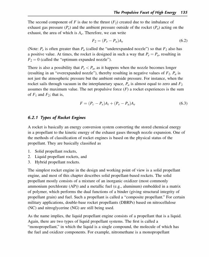
The second component of F is due to the thrust (F2) created due to the imbalance of
exhaust gas pressure (Pe) and the ambient pressure outside of the rocket (Pa) acting on the
exhaust, the area of which is Ae. Therefore, we can write
F2 ¼ ðPe � PaÞAe (6.2)
(Note: Pe is often greater than Pa (called the “underexpanded nozzle”) so that F2 also has
a positive value. At times, the rocket is designed in such a way that Pe ¼ Pa, resulting in
F2 ¼ 0 (called the “optimum expanded nozzle”).
There is also a possibility that Pe < Pa, as it happens when the nozzle becomes longer
(resulting in an “overexpanded nozzle”), thereby resulting in negative values of F2. Pa is
not just the atmospheric pressure but the ambient outside pressure. For instance, when the
rocket sails through vacuum in the interplanetary space, Pa is almost equal to zero and F2
assumes the maximum value. The net propulsive force (F) a rocket experiences is the sum
of F1 and F2; that is,
F ¼ ðPc � PeÞAt þ ðPe � PaÞAe (6.3)
6.2.1 Types of Rocket Engines
A rocket is basically an energy conversion system converting the stored chemical energy
in a propellant to the kinetic energy of the exhaust gases through nozzle expansion. One of
the methods of classification of rocket engines is based on the physical status of the
propellant. They are basically classified as
1. Solid propellant rockets,
2. Liquid propellant rockets, and
3. Hybrid propellant rockets.
The simplest rocket engine in the design and working point of view is a solid propellant
engine, and most of this chapter describes solid propellant-based rockets. The solid
propellant mostly consists of a mixture of an inorganic oxidizer (most commonly
ammonium perchlorate (AP)) and a metallic fuel (e.g., aluminum) embedded in a matrix
of polymer, which performs the dual functions of a binder (giving structural integrity of
propellant grain) and fuel. Such a propellant is called a “composite propellant.” For certain
military applications, double-base rocket propellants (DBRPs) based on nitrocellulose
(NC) and nitroglycerine (NG) are still being used.
As the name implies, the liquid propellant engine consists of a propellant that is a liquid.
Again, there are two types of liquid propellant systems. The first is called a
“monopropellant,” in which the liquid is a single compound, the molecule of which has
the fuel and oxidizer components. For example, nitromethane is a monopropellant
The Propulsive Facet of High Energy 135
containing the fuel elements (carbon and hydrogen) and oxygen as the oxidizer. In any
liquid rocket engines, the liquid propellant must be stored separately in a tank and needs
to be pumped into the combustion chamber for operation. Figure 6.3 gives a schematic
representation of a liquid monopropellant engine.
The second type of liquid rocket engine is based on a bipropellant system in which the
oxidizer (in liquid form) and fuel (in liquid form) are separately stored in tanks. The
oxidizer and fuel are pumped as per the required ratio into the rocket chamber for
operation (Figure 6.4). This system obviously has more moving parts because of two
separate flow systems; therefore, it has its own problems. Some of the well-known
examples of bipropellant systems are as follows:
Oxidizer: Red fuming nitric acid (RFNA), hydrogen peroxide, and liquid oxygen
Fuel: Aromatic amines.
When we compare a solid propellant engine with a liquid propellant one, each has its
advantages and disadvantages. For example, the design of a solid propellant grain is
simpler and it does not have any additional moving parts (e.g., turbine/valve, etc.).
However, once the solid propellant is ignited, it is difficult to stop or control the
combustion whereas the flow of liquid oxidizer/fuel can be controlled.
In space programs and in advanced long-range ballistic missiles, the liquid propellant
system is used either alone or along with a solid propellant system in different stages
depending on the mission requirements.
The third type of rocket engine is called the “hybrid type” because it combines a solid
(fuel/oxidizer) and a liquid (oxidizer/fuel). It is schematically shown in Figure 6.5. The
liquid part (oxidizer; e.g., RFNA) is pumped into the rocket chamber containing the solid
fuel (e.g., a polyurethane polymer). The hybrid propellant system has its own advantages
and disadvantages of solid and liquid propellant systems.
Mono Propellant
Pump Valve
Nozzle
Combustion Chamber
Turbine
Figure 6.3Schematic Representation of a Liquid Monopropellant Rocket Engine.
136 Chapter 6
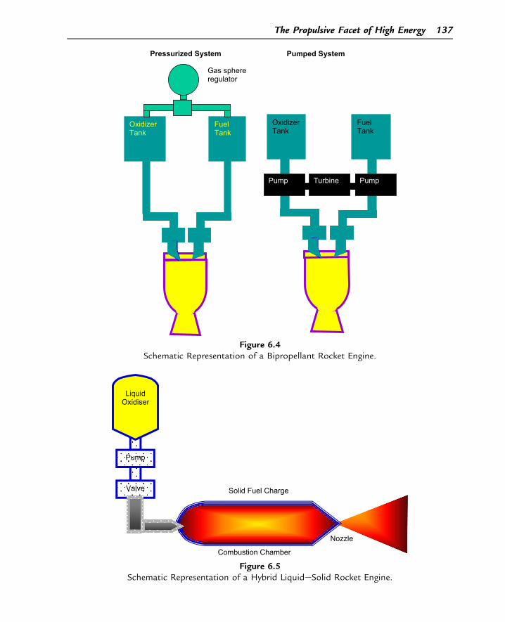
Oxidizer Tank
Fuel Tank
Gas sphere regulator
Pressurized System
Oxidizer Tank
Fuel Tank
Turbine PumpPump
Pumped System
Figure 6.4Schematic Representation of a Bipropellant Rocket Engine.
LiquidOxidiser
Pump
Valve Solid Fuel Charge
Nozzle
Combustion Chamber
Figure 6.5Schematic Representation of a Hybrid LiquideSolid Rocket Engine.
The Propulsive Facet of High Energy 137
6.3 Specific Impulse
Rocket designers have always been striving to achieve one goaldnamely, to design a
rocket
1. That can carry heavier payloads,
2. That can have longer ranges, and
3. In which the propellant consumption is minimal (analogous to fuel efficiency in
automobiles).
Factors 1 and 2 demand that the total impulse developed by the rocket is quite high. Total
impulse (I) is defined as I¼ F� t where F is the thrust developed by the rocket acting for
a duration of time (t). In others words, factors 1 and 2 are directly proportional to F � t.
For complying with factor 3, the weight of the propellant consumed during the rocket
flight (w) should be as little as possible. The term that considers these factors together to
express the overall efficiency of a rocket propulsion system is called the “specific impulse”
denoted by Isp.
Isp is accordingly expressed as
Isp ¼ F � t
w(6.4a)
This expression can also be written as
Isp ¼R
Fdt
w(6.4b)
(or)
Isp ¼ F
w� (6.4c)
where, w�is the rate of consumption of propellant, being equal to dw
dt .
6.3.1 The Unit of Isp
From Eqn (6.4a), we can see that F (i.e., thrust) and w (i.e., weight) have the same
unitsdkilogram$meters per second squared (kg m s�2; using SI units). Because they
cancel out, only t remains. Therefore, specific impulse has the unit of seconds. For
example, we can say that a given a propellant has an Isp of 240 s.
138 Chapter 6
6.3.2 Isp and Exhaust Velocity of Gases
Let us consider a rocket cruising at a uniform velocity, and let the rocket function under
the optimum nozzle expansion condition so that the second term in Eqn (6.3) is reduced to
zero. If the exhaust gas velocity of the gases is v and the rate of loss of weight of the
propellant (due to propellant burning) is w�, then the thrust (F) of the rocket, according to
Newton’s Second Law of Motion, is equal to the rate of change of momentum, which can
be expressed as
F ¼ d
dtðmvÞ ¼ m
dv
dtþ v
dm
dt¼ mv
� þ vm�
Because the rocket is moving with uniform velocity (i.e., v� ¼ 0), in this case
F ¼ m�v ¼ w
�v
g(6.5)
(Because m ¼ w=g).
Substituting this in Eqn (6.4c),
Isp ¼ w�v
g� 1
w� ¼ v
g
Isp ¼ v
g(6.6)
Therefore, Isp is directly proportional to the exhaust velocity of gases (v).
Therefore, it is obvious that a propulsion scientist always endeavors to design his
rocketdthe hardware and the propellantdto achieve the highest possible value for the
exhaust velocity (v).
Worked Example 6.1
A rocket develops a thrust of 10 tons by consuming 200 kg of propellant in 5 s. Calculate
the specific impulse of the propellant used.
The rate of propellant consumption ¼ 200 kg
5 s
w� ¼ 40 kg s�1
Isp ¼ F
w� ¼ 10; 000 kg
40 kg s�1¼ 250 s
Why are we so specific about specific impulse?
The Propulsive Facet of High Energy 139
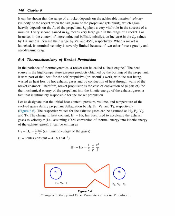
It can be shown that the range of a rocket depends on the achievable terminal velocity
(velocity of the rocket when the last gram of the propellant gets burnt), which again
heavily depends on the Isp of the propellant. Isp plays a very vital role in the success of a
mission. Every second gained in Isp means very large gain in the range of a rocket. For
instance, in the context of intercontinental ballistic missiles, an increase in the Isp values
by 1% and 5% increase their range by 7% and 45%, respectively. When a rocket is
launched, its terminal velocity is severely limited because of two other forces: gravity and
aerodynamic drag.
6.4 Thermochemistry of Rocket Propulsion
In the parlance of thermodynamics, a rocket can be called a “heat engine.” The heat
source is the high-temperature gaseous products obtained by the burning of the propellant.
It uses part of that heat for the self-propulsive (or “useful”) work, with the rest being
wasted as heat loss by hot exhaust gases and by conduction of heat through walls of the
rocket chamber. Therefore, rocket propulsion is the case of conversion of (a part of) the
thermochemical energy of the propellant into the kinetic energy of the exhaust gases, a
fact that is ultimately responsible for the rocket propulsion.
Let us designate that the initial heat content, pressure, volume, and temperature of the
evolved gases during propellant deflagration be H1, P1, V1, and T1, respectively
(Figure 6.6). The respective values for the exhaust gases can be assumed as H2, P2, V2,
and T2. The change in heat content, H1 e H2, has been used to accelerate the exhaust
gases to velocity v (i.e., assuming 100% conversion of thermal energy into kinetic energy
of the exhaust gases). It can be written as
H1 � H2 ¼ 12mv2
J (i.e., kinetic energy of the gases)
(J ¼ Joules constant ¼ 4.18 J cal�1)
H1 � H2 ¼ 1
2
w
g
v2
J
P1, V1, T1
H1 H2
P2, V2, T2
Figure 6.6Change of Enthalpy and Other Parameters in Rocket Propulsion.
140 Chapter 6
v ¼ffiffiffiffiffiffiffiffiffiffiffiffiffiffiffiffiffiffiffiffiffiffiffiffiffiffiffiffi
2gJðH1 � H2Þw
r
(6.7)
Assuming that the entire process is completely adiabatic (i.e., no heat is allowed to enter
or leave the rocket motor system), it can be shown that
Isp ¼ffiffiffiffiffiffiffiffiffiffiffiffiffiffiffiffiffiffiffiffiffiffiffiffiffiffiffiffiffiffiffiffiffiffiffiffiffiffiffiffiffiffiffiffiffiffiffiffiffiffiffiffiffiffiffiffiffiffi
2RT
Mg
�
g
g� 1
�
"
1��
Pe
Pc
�
g�1g
#
v
u
u
t (6.8)
where M ¼ the average molecular weight of the exhaust gases, T ¼ the flame temperature
of the propellant, Pe ¼ the pressure of the exhaust gases, Pc ¼ the chamber pressure,
g ¼ the ratio of specific heats of the gases (average value), and R ¼ is the universal gas
constant.
For a given set of values for Pe and Pc, assuming that the value of g has only a limited
influence, it is seen that the Isp of a rocket propellant mainly depends on the adiabatic
flame temperature of the propellant and the average molecular weight of the exhaust gas
products. The higher values of T and lower values of M favor higher Isp values. Equation
(6.8) can be written in a simplified manner as
Isp a
ffiffiffiffiffiffi
RT
M
r
(6.9)
As mentioned earlier, the average molecular weight of exhaust gases and the flame
temperature (isochoric in the case of gun propellants and isobaric for rocket propellants)
of propellants greatly influence their performance. Although in the case of gun propellants
their performance parameter, the force constant, is directly proportional to nRTv, the
performance parameter of a rocket propellant, Isp, varies in direct proportion to the square
root of nRTp. (Note: n ¼ 1/M.) The theoretical Isp calculated for a given propellant (as
calculated in the above worked example) does not exactly agree with the Isp measured
when the a rocket is fired. It is because, in theory, we assume the performance of the
rocket under ideal conditions, which deviate from the actual conditions of performance, is
as follows:
1. The high-pressure gases inside of the rocket motor do not completely obey ideal gas laws.
2. The rocket motor does not ensure 100% thermal insulation, and the perfect adiabaticity
of performance cannot be assumed.
3. The composition/homogeneity of the gases is not uniform through the entire length of
flow.
4. The chemical equilibrium gets continuously shifted throughout the flow.
5. There are losses due to multidimensional flow. (In an ideal rocket, the flow is in one
dimension only; i.e., along the x-axis.)
The Propulsive Facet of High Energy 141
6. There is heat loss due to friction and other dissipative factors.
Because of these deviations, the delivered Isp of a rocket is always less than the
theoretical Isp.
6.5 Some Vital Parameters in the Internal Ballistics of Rockets
It is proposed to highlight the importance of some parameters that greatly influence the
rocket performance.
6.5.1 Linear Burning Rate
The linear burning rate (LBR; r) of a solid propellant grain decides the value of the mass
burning rate, which is sometimes referred to as the “mass flow rate” (m�). You may recall
we have related these two parameters as
m� ¼ rAr;
where A and r refer to the surface area exposed for burning and the density of the
propellant, respectively.
The parameters r and m�greatly affect the performance time of the rocket, the pressure
build-up pattern in the rocket chamber, etc. In the case of a solid rocket propellant grain,
the value of r depends on the factors presented in the following subsections.
6.5.1.1 Chamber Pressure
In the case of DBRPs (based on NC and NG), r and the pressure chamber (Pc) are related
as
r ¼ bPnc (6.10)
This equation is known as Vielle’s law, in which n is the pressure exponent and b is the
burning rate coefficient. It takes the logarithmic form as (see Figure 6.7)
log r ¼ log bþ n log Pc (6.11)
At a given temperature, a plot of log r against log Pc yields a straight line, the slope of
which yields the value of n. This is an empirical law, generally obeyed by double-base
propellants mostly in the range of conventional operating pressures (from 20 to
100 kg cm�2). Composite propellants (i.e., propellants containing a polymeric fuel
cum binder containing uniform dispersion of an oxidizer such as AP and metallic fuel
such as aluminum powder) do not obey this law. Although a perfect model for
composite propellant burning has not been developed so far, Summerfield’s model
142 Chapter 6
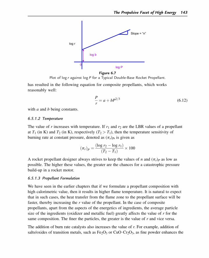
has resulted in the following equation for composite propellants, which works
reasonably well:
P
r¼ aþ bP2=3 (6.12)
with a and b being constants.
6.5.1.2 Temperature
The value of r increases with temperature. If r1 and r2 are the LBR values of a propellant
at T1 (in K) and T2 (in K), respectively (T2 > T1), then the temperature sensitivity of
burning rate at constant pressure, denoted as (pr)P, is given as
ðprÞP ¼ ðlog r2 � log r1ÞðT2 � T1Þ � 100
A rocket propellant designer always strives to keep the values of n and (pr)P as low as
possible. The higher these values, the greater are the chances for a catastrophic pressure
build-up in a rocket motor.
6.5.1.3 Propellant Formulation
We have seen in the earlier chapters that if we formulate a propellant composition with
high calorimetric value, then it results in higher flame temperature. It is natural to expect
that in such cases, the heat transfer from the flame zone to the propellant surface will be
faster, thereby increasing the r value of the propellant. In the case of composite
propellants, apart from the aspects of the energetics of ingredients, the average particle
size of the ingredients (oxidizer and metallic fuel) greatly affects the value of r for the
same composition. The finer the particles, the greater is the value of r and vice versa.
The addition of burn rate catalysts also increases the value of r. For example, addition of
salts/oxides of transition metals, such as Fe2O3 or CuO$Cr2O3, as fine powder enhances the
0log P
log r
log b
Slope = “n”
Figure 6.7Plot of log r against log P for a Typical Double-Base Rocket Propellant.
The Propulsive Facet of High Energy 143
value of r. It is believed that electrons in the half-filled d orbitals of these transition metal
atoms accelerate the decomposition of the AP (oxidizer) used in the composite propellants.
6.5.1.4 Erosive Burning
When high-velocity gases from the propellant erode the propellant surface, it results in
faster heat transfer between the gas phase and solid phase, thereby increasing the value of r.
6.5.2 Characteristic Velocity
Referring back to the schematic representation of a rocket in Figure 6.1, let us ask: “What
are the roles of propellants and the rocket nozzle in the rocket performance?” The first
compartment (i.e., the chamber) ensures that the propellant burns as per the designed
pressure-time profile and the high-pressure, high-temperature gases are ready to get into
the nozzle to manifest their power. The total thermochemical energy of the propellant is
being transformed into a high potential system ready for expansion through the nozzle.
This thermochemical output is represented by the term “characteristic velocity” (C*;
pronounced as “see star”), which represents the thermochemical potential of the
propellant.
The nozzle then takes over. The high-pressure gases are initially compressed through the
convergent portion of the nozzle and then expanded with enormous power through its
divergent portion. The efficiency of nozzle expansion, which determines the value of the
exhaust velocity of gases, is called the “thrust coefficient” (CF), which is basically a thrust
amplification factor. C* is characteristic of a propellant in combination with the chamber
and is independent of nozzle design. On the other hand, CF is a thrust amplification factor
and depends on the nozzle design. CF is given by the equation
CF ¼ F
PCAt(6.13)
The numerator in the right-hand term of the equation refers to the realized thrust whereas
the denominator refers to the thrust experienced at the throat before it is amplified by the
divergent section of the nozzle. Because the exhaust velocity (v) is determined by C* and
CF, it can be written
v ¼ C �CF (6.14)
Therefore, C* can be defined as the exhaust velocity of the gases when their pressure does
not undergo any amplification by the nozzle (CF ¼ 1). However,
Isp ¼ v
gfrom Eqn ð6:6Þ
Therefore; Isp ¼ C �CF
g(6.15)
144 Chapter 6
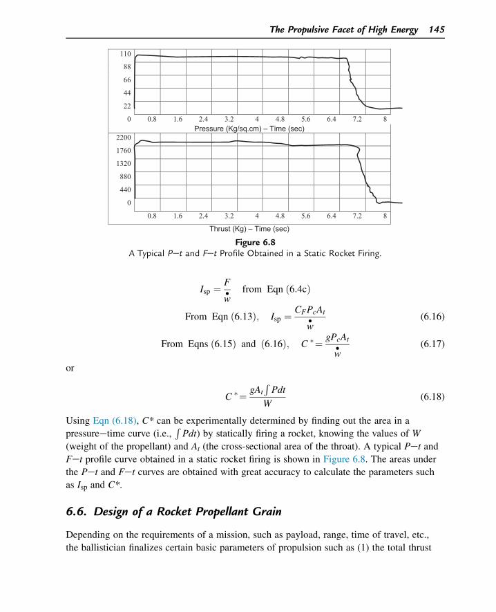
Isp ¼ F
w� from Eqn ð6:4cÞ
From Eqn ð6:13Þ; Isp ¼ CFPcAt
w� (6.16)
From Eqns ð6:15Þ and ð6:16Þ; C �¼ gPcAt
w� (6.17)
or
C �¼ gAt
R
Pdt
W(6.18)
Using Eqn (6.18), C* can be experimentally determined by finding out the area in a
pressureetime curve (i.e.,R
Pdt) by statically firing a rocket, knowing the values of W
(weight of the propellant) and At (the cross-sectional area of the throat). A typical Pet and
Fet profile curve obtained in a static rocket firing is shown in Figure 6.8. The areas under
the Pet and Fet curves are obtained with great accuracy to calculate the parameters such
as Isp and C*.
6.6. Design of a Rocket Propellant Grain
Depending on the requirements of a mission, such as payload, range, time of travel, etc.,
the ballistician finalizes certain basic parameters of propulsion such as (1) the total thrust
110
88
66
44
22
0 0.8 1.6 2.4 3.2 4 4.8 5.6 6.4 7.2 8Pressure (Kg/sq.cm) – Time (sec)
2200
1760
1320
880
440
0
0.8 1.6 2.4 3.2 4 4.8 5.6 6.4 7.2 8
Thrust (Kg) – Time (sec)
Figure 6.8A Typical Pet and Fet Profile Obtained in a Static Rocket Firing.
The Propulsive Facet of High Energy 145
needed, (2) the weight of the propellant (1 and 2 decide the Isp of the propellant), (3) the
action time (i.e., propellant burning time), (4) the density of the propellant, (5) the
pressure index of the propellant, (6) the pressure at which the propellant should burn, (7)
the Ae/At ratio, etc. Considering the mission requirements and the interdependence of
many ballistic parameters, the ballistician has only a narrow choice. Once they finalize
these, they turn to the propellant chemist and demand that the propellant must have
characteristics such as
• An Isp of x seconds,
• A C* of y ms�1,
• An LBR of z mm s�1 at P kg cm�2,
• A pressure index in the range of n1 and n2,
• A density of r g cm�3, etc.
It is now for the propellant chemist to use their expertise to formulate a composition that
meets the demands of the ballistician. This is easier said than done. When they achieve
one parameter (e.g., Isp), some other parameters may start slipping away. For example,
some of the higher energy (Isp) versions of the solid rocket propellants may meet the
demands of Isp and C* but may miserably fail in the requirement of pressure index. Or,
they theoretically may feel confident about a particular formulation, but when they go to
the process plant, they discover to their dismay that the composition is just not processable
because the polymeric binder is too viscous to take the required solid loading of oxidizer
and metallic fuel. It is like walking over a tight rope before the propellant chemist zeroes
onto a certain formulation that satisfies the demands of the ballistician.
It is very often possible that the propellant chemist may not meet the demands of the
ballistician exactly and there are slight variations. The ballistician then fine-tunes their
design. Let us consider an example of a sustainer-type rocket propellant that burns from
one end similar to a cigarette. The propellant chemist has finalized what they can offer and
the ballistician works out the following parameters in sequence: (1) mass of the propellant,
(2) the average burning surface, (3) the diameter of the grain, (4) the length of the grain,
(5) the ratio of the burning area of the propellant at a given time to the area of the throat
of the nozzle (called the KN ratio), (6) the throat area (At), (7) the throat diameter, and (8)
the area of the exit portion of the nozzle (Ae) on the basis of the Ae/At requirement.
Worked Example 6.2
How will you design a grain (cigarette-burning mode) of a rocket propellant considering
the following requirements? (1) Isp ¼ 200 s, (2) r ¼ 0.5 in s�1 at 1500 psi (which is the
operating pressure), (3) KN ¼ 400 at 1500 psi, (4) density of the propellant ¼ 0.05 lb in�3,
(5) Ae/At ¼ 10, (6) thrust required ¼ 1000 lb, and (7) burning time required ¼ 20 s.
146 Chapter 6
The sequence of calculation proceeds as follows:
1. Propellant weight : F�tbIsp
¼ 1000�20200 ¼ 100 lb
2. Grain length : l ¼ ðr � tbÞ ¼ 0:5� 20 ¼ 10 in
3. Grain volume : WeightDensity ¼ 100
0:05 ¼ 2000 in3
4. Propellant diameter ðDÞ : Volume ¼�
pD2l4
�
; Substituting the value for volume and
length, D ¼ 16 in
5. Propellant burning area : Ab ¼ pD2
4 ¼ 200 in2
(Cigarette-burning mode)
6. Area of the throat (At)
Since KN ¼ Ab
At¼ 400; At ¼ Ab
400 ¼ 200400 ¼ 0:5 in2
7. Area of the exit (Ae)
SinceAe
Atshould be 10;
Ae
0:5¼ 10; Ae ¼ 5 in2
The above seven parameters are calculated by the ballistician so that they can accordingly
design and fabricate the rocket motor to realize their requirements using the above
propellant. This is probably the simplest example that can be given to make beginners
understand the methodology of grain design. In actual practice, it is far more complicated,
particularly while dealing with large grains with complex internal configurations. The
propellant design might need modification by considering factors such as the extent of
erosive burning, combustion instability, compatibility with the ignition system, etc.
6.7. Chemistry of Solid Rocket Propellants6.7.1. Choices and Limitations
As already mentioned, the job of a propellant chemist is unenviable. They get the
requirement from the ballistician, and then their rope walking commences. The chemist
has to take into account several factors that the propellant should satisfy, and the major
ones are presented in the following subsections.
6.7.1.1 The Energetics
It is precisely the specific impulse (Isp), the index of energy of any rocket propellant, that
needs major consideration. Isp varies depending on the nature of propellant. We have seen
(Eqn (6.8)) that for a given chamber and exit pressure, Isp mainly depends on the flame
temperature and the average molecular weight of the products. We have seen in detail in
Chapter 2 that the flame temperature depends on the calorimetric value (heat of explosion)
The Propulsive Facet of High Energy 147
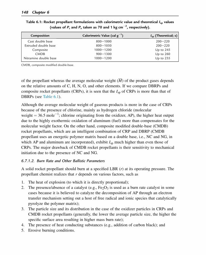
of the propellant whereas the average molecular weight (M) of the product gases depends
on the relative amounts of C, H, N, O, and other elements. If we compare DBRPs and
composite rocket propellants (CRPs), it is seen that the Isp of CRPs is more than that of
DBRPs (see Table 6.1).
Although the average molecular weight of gaseous products is more in the case of CRPs
because of the presence of chlorine, mainly as hydrogen chloride (molecular
weight ¼ 36.5 mole�1; chlorine originating from the oxidizer, AP), the higher heat output
due to the highly exothermic oxidation of aluminum (fuel) more than compensates for the
molecular weight factor. On the other hand, composite modified double-base (CMDB)
rocket propellants, which are an intelligent combination of CRP and DBRP (CMDB
propellant uses an energetic polymer matrix based on a double base, i.e., NC and NG, in
which AP and aluminum are incorporated), exhibit Isp much higher than even those of
CRPs. The major drawback of CMDB rocket propellants is their sensitivity to mechanical
initiation due to the presence of NC and NG.
6.7.1.2. Burn Rate and Other Ballistic Parameters
A solid rocket propellant should burn at a specified LBR (r) at its operating pressure. The
propellant chemist realizes that r depends on various factors, such as
1. The heat of explosion (to which it is directly proportional);
2. The presence/absence of a catalyst (e.g., Fe2O3 is used as a burn rate catalyst in some
cases because it is believed to catalyze the decomposition of AP through an electron
transfer mechanism setting out a host of free radical and ionic species that catalytically
pyrolyze the polymer matrix);
3. The particle size and its distribution in the case of the oxidizer particles in CRPs and
CMDB rocket propellants (generally, the lower the average particle size, the higher the
specific surface area resulting in higher mass burn rate);
4. The presence of heat conducting substances (e.g., addition of carbon black); and
5. Erosive burning conditions.
Table 6.1: Rocket propellant formulations with calorimetric value and theoretical Isp values
(values of Pc and Pe taken as 70 and 1 kg cm�2, respectively).
Composition Calorimetric Value (cal g�1) Isp (Theoretical; s)
Cast double base 800e1000 200e220Extruded double base 800e1050 200e220
Composite 1000e1200 Up to 245CMDB 900e1300 Up to 260
Nitramine double base 1000e1200 Up to 235
CMDB, composite modified double-base.
148 Chapter 6
Apart from burn rate catalysts, in some cases, certain substances need to be added in the
propellant composition to ensure that the value of r does not change between certain
pressure ranges. This is called a “plateau” condition, and the substances added for this
purpose are called “platonizers” (see Figure 6.9).
Addition of platonizing agents, such as basic lead stearate in DBRPs, has been found to be
effective in achieving a pressure independence of the burn rate between certain pressure
ranges (P1 to P2). The value of the pressure exponent n is nearly zero in this region.
Substances such as basic lead stearate, basic lead salicylate, etc., have been successfully
used to achieve platonization in DBRPs.
6.7.1.3. Processability
While taking care of the energetics, the propellant formulator has to consider the
processability of what he intends to formulate. He will have to carefully analyze the
interdependence of various factors of processability and choose the most optimal
formulation. Let us illustrate this with an example of a CRP formulation.
A CRP contains an oxidizer (mostly AP) and a metallic powder (e.g., aluminum powder)
dispersed in a polymeric matrix (e.g., a polyurethane matrix that plays the dual role of
binding AP and aluminum, thereby structural integrity to the propellant grain and a fuel).
The formulation also contains smaller percentages of other ingredients such as a
plasticizer, process aid, burn rate catalyst, etc. A typical composition is as follows:
1. AP ¼ 68% (2:1 mixture of coarse AP (w250 mm) and fine AP (w10 mm)),
2. Aluminum ¼ 17%,
3. Polymer ¼ 15% (polyurethane, based on hydroxyl terminated polybutadiene (HTPB)),
and
4. One part of Fe2O3 (burn rate catalyst).
A B
P1 P2
Unplatonized propellant(slope = n)
Platonized propellant
log P
log r
Figure 6.9Plateau Effect.
The Propulsive Facet of High Energy 149
The major steps involved are as follows:
1. Ingredient preparation
a. Drying of AP and blending of the coarse and fine varieties (it is called “bimodal
AP.” The purpose of blending coarse and fine AP is to achieve maximum loading of
AP in the thick viscous “prepolymer”-like HTPB before the prepolymer is cured.
Remember the mason mixing fine cement with sand particles of various sizes while
making concrete mixture? Such a multimodal mixing ensures that the interstices
between bigger particles are filled by smaller particles ensuring maximum space
utilization).
b. Drying of aluminum powder.
c. Drying of HTPB, plasticizers, etc.
2. Mixing
All of the above ingredients are mixed in a mixer.
3. Addition of curative
The addition of curative sets in the curing reaction. In our example, addition of
toluene di-isocyanate (TDI) starts the curing reaction (the NCO groups of TDI react
with the terminal OH groups of HTPB forming the urethane, NH.COOR linkage
between HTPB prepolymer molecules), and the slurry mix becomes more viscous.
4. Casting
The slurry is cast into an inner-lined rocket motor fitted with a mandrel. (Note: The
slurry should be poured/cast into the motor before its viscosity increases beyond a
certain level.)
5. Curing
The rocket motor into which the propellant slurry has been cast is kept in an oven, the
temperature of which may be approximately 70 �C for approximately 7 days.
6. Mandrel removal after removal of the rocket motor from oven and cooling. The propel-
lant curing process is over and the mandrel is carefully removed. After necessary in-
spection (e.g., X-ray inspection to ensure the absence of defects such as cracks and
voids in the solid grain), the motor is ready for firing after further assembly.
Let us say that the above formulation realizes the following performance parameters:
Isp y 245 s, burn rate ¼ 10 mm s�1 at 70 kg cm�2
If the propellant chemist is asked to modify the composition so as to increase the Isp to
250 s without affecting the burn rate, then what options are left to them and with what
consequences?
150 Chapter 6
Option 1
Because Isp is directly proportional to flame temperature and heat of explosion, they can
go in for higher loading of AP and aluminum so that the solid loading goes from 85% to
87%.
Consequence 1
This 2% increase in solid loading is too much for the HTPB prepolymer to take. It
becomes difficult to mix. Even if they manage to mix, the viscosity increase of the mix
after the addition of curative is too fast for smooth casting. The propellant made out of
this mix is very likely to contain many voids that are unacceptable.
Consequence 2
Higher AP and aluminum means higher flame temperature, which will increase the burn
rate beyond 10 mm s�1, which also is unacceptable.
Consequence 3
A lower percentage of the polymeric matrix in the final propellant will adversely affect the
mechanical property of the propellant, leading to a lower percentage of elongation and a
lower glass transition temperature.
Option 2
Increase the solid loading by 2% but compensate it by decreasing the ratio of finer AP so
that viscosity increase can be taken care of.
Consequence 1
When the percentage of fine AP decreases (or that of coarse AP increases), the burn rate
of the final propellant will decrease, which is not acceptable.
Consequence 2
A large increase in coarse AP percentage will also affect the mechanical property of the
final propellant by reducing its tensile strength.
Option 3
Increase the solid loading by 2% but use the prepolymer HTPB of lower viscosity to take
care of the viscosity build-up.
Consequence 1
Lower viscosity means lesser chain length/molecular weight of HTPB, and this will result
in poor mechanical property of the final grain.
The Propulsive Facet of High Energy 151
Consequence 2
A higher burn rate.
The above is just one example of the complex interplay of various parameters of
formulation viz-a-viz the processability. The propellant chemist needs to blend chemistry
and experience to solve such problems for which there are no quick-fix solutions.
6.7.1.4. Mechanical Properties
A rocket propellant grain has to withstand various mechanical stresses right from the time
it is made until it is used. At various stages such as transportation, storage, assembly, and
actual flight it undergoes tensile and compressive loads, shocks, vibration, high G values,
etc., and if the mechanical properties of the grain are too poor to withstand such stresses,
then it will result in the formation of abnormalities such as cracks, which are highly
disastrous. In general, a propellant grain, which is free-standing and gets loaded to a motor
after inhibition, requires a high tensile strength. In the case of case-bonded propellant
charges (i.e., in which the propellant is directly cast into lined motors in situ), the grain
should be able to take high compressive load and should therefore have higher elongation.
6.7.1.5. Storage Stability/Life
The rocket propellants, particularly meant for military use, are stored in assembled motors
for a long period under varying conditions of temperature and humidity. The propellant
chemist has to carefully analyze the compatibility among various ingredients that are used
in propellant processing. For instance, an incompatible ingredient may accelerate the
breakdown of the polymer matrix in a propellant, resulting in the development of cracks.
There are well-established methods, such as several surveillance tests and thermal
analyses, which can help in assessing such incompatibilities.
6.7.1.6 Safety and Environment: Cause for Concern
Safety is the most important factor that should be foremost on the mind of any HEM
chemist. They are handling materials that have all of the three types of risks: explosion,
fire, and toxicity. It is a known fact that under extreme conditions, such as undue
confinement, a propellant or many of its ingredients can violently detonate. Fire risk is
always there with any type of propellant. Quite a few chemicals used in propellant
processing are carcinogenic and mutagenic. When the propellant is finally processed, it
must be reasonably insensitive to impact, friction, and static discharge. There is no
relevance in formulating a high-energy propellant that is quite dangerous to handle.
All over the world, the propellant scientists and technologists are exploring the possibility
of going in for ecofriendly or “green” propellants and propellant ingredients. For example,
despite many of its attractive properties (e.g., low cost, better energetics, and stability), AP
152 Chapter 6
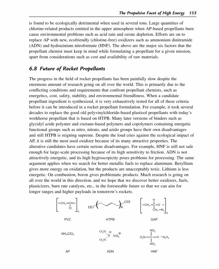
is found to be ecologically detrimental when used in several tons. Large quantities of
chlorine-related products emitted in the upper atmosphere when AP-based propellants burn
cause environmental problems such as acid rain and ozone depletion. Efforts are on to
replace AP with new, ecofriendly (chlorine-free) oxidizers such as ammonium dinitramide
(ADN) and hydrazinium nitroformate (HNF). The above are the major six factors that the
propellant chemist must keep in mind while formulating a propellant for a given mission,
apart from considerations such as cost and availability of raw materials.
6.8 Future of Rocket Propellants
The progress in the field of rocket propellants has been painfully slow despite the
enormous amount of research going on all over the world. This is primarily due to the
conflicting conditions and requirements that confront propellant chemists, such as
energetics, cost, safety, stability, and environmental friendliness. When a candidate
propellant ingredient is synthesized, it is very exhaustively tested for all of these criteria
before it can be introduced in a rocket propellant formulation. For example, it took several
decades to replace the good old polyvinylchloride-based plastisol propellants with today’s
workhorse propellant that is based on HTPB. Many later versions of binders such as
glycidyl azide polymer and oxetane-based polymers and copolymers containing energetic
functional groups such as nitro, nitrato, and azido groups have their own disadvantages
and still HTPB is reigning supreme. Despite the loud cries against the ecological impact of
AP, it is still the most used oxidizer because of its many attractive properties. The
alterative candidates have certain serious disadvantages. For example, HNF is still not safe
enough for large-scale processing because of its high sensitivity to friction. ADN is not
attractively energetic, and its high hygroscopicity poses problems for processing. The same
argument applies when we search for better metallic fuels to replace aluminum. Beryllium
gives more energy on oxidation, but the products are unacceptably toxic. Lithium is less
energetic. On combustion, boron gives problematic products. Much research is going on
all over the world in this direction, and we hope that we discover better oxidizers, fuels,
plasticizers, burn rate catalysts, etc., in the foreseeable future so that we can aim for
longer ranges and higher payloads in tomorrow’s rockets.
HOOH( )x
CH2 CH
nCl
CH2 C
CH2 N3n
H
O
PVC HTPB GAP
NH4ClO4O2N
NO2N
NH4 O2N C H * N2H4
NO2
NO2
AP ADN HNF
The Propulsive Facet of High Energy 153
PVC: Polyvinylchloride
HTPB: Hydroxyl terminated polybutadiene
GAP: Glycidyl azide polymer
AP: Ammonium perchlorate
ADN: Ammonium dinitramide
HNF: Hydrazinium nitroformate.
Suggested Reading
[1] R. Meyer, J. Kohler, Explosives, VCH Publishers, Germany, 1993 (Encyclopaedia e handy for referencing).[2] T. Urbanski, Chemistry and Technology of Explosives, vol. 1e4, Pergamon Press, Oxford, New York, 1983.[3] A. Bailey, S.G. Murray, Explosives, Propellants and Pyrotechnics, Pergamon Press, Oxford, New York,
1988.[4] B. Siegel, L. Schieler, Energetics of Propellant Chemistry, John Wiley & Sons. Inc., New York, 1964.[5] S.F. Sarner, Propellant Chemistry, Reinhold Publishing Corporation, New York, 1966.[6] S. Fordham, High Explosives and Propellants, Pergamon Press, Oxford, New York, 1980.[7] J.P. Agarwal, High Energy Materials, Propellants, Explosives and Pyrotechnics, Wiley, 2010.[8] N. Kubota, Propellants and Explosives Thermochemical Aspects of Combustion, 2007.
Questions
1. What are the two major parts of a solid rocket motor?
2. What is the role of a CD nozzle in a rocket motor?
3. Can you explain, using the thrust equation, why the thrust experienced by a rocket is
maximal while it traverses through vacuum?
4. What are the relative merits and demerits of solid and liquid rocket engines?
5. Explain why the unit of specific impulse is expressed in seconds and how it is related
to the exhaust velocity of gases.
6. Calculate the weight of a solid rocket propellant (Isp ¼ 210 s) that should be loaded in
a rocket motor to produce a thrust of 6 tons. The propellant burns for 4 s (Answer:
114.3 kg).
7. What are the two major characteristics that decide the value of its specific impulse?
8. What are the factors that reduce the actual (realized) Isp of the propellant compared
with the theoretical Isp calculated?
9. What is Vielle’s law and why must a propellant chemist be worried about the value of
n, the pressure index?
10. What is the significance of C*?
11. Why is the job of a rocket propellant chemist similar to walking on a rope?
154 Chapter 6

12. Why are CMDB propellants more energetic than the composite and double-base
propellants?
13. What are the major steps involved in processing composite propellants?
14. Case-bonded rocket propellants should have high compressive strength and elongation.
Why?
15. Name some of the potential candidates for polymeric binders, fuels, and oxidizers for
use in solid rocket propellants.
The Propulsive Facet of High Energy 155

This page intentionally left blank
CHAPTER 7
High Energy Materials in Pyrotechnics
7.1 Introduction
Common man understands rather simplistically that “pyrotechnics” means fireworks. It is
generally known that the first people to develop fireworks were the Chinese more than
1000 years ago. The Chinese were experts in the field of pyrotechnics, and as early as the
tenth century they had developed rockets. As mentioned in Chapter 1, the English scientist
Roger Bacon made a quantitative study of gunpowder during the thirteenth century, and the
use of gunpowder as a propellant for cannons was prevalent in Europe in the fourteenth
century. When the application of pyrotechnics (meaning the art of making and using
fireworks) underwent a transition from civilian use to military use, enormous efforts to
search for suitable chemicals and innovation in formulation and processing led to significant
progress in the field of pyrotechnics.
7.2 Applications
Let us consider the following scenario. A multistage rocket takes off either for a military
or for a space mission. First-stage propulsion is only possible if the propellant is suitably
ignited by an igniter, which is basically a pyrotechnic composition. In the case of one-
stage, small-size rockets, it may be a cartridge containing gunpowder of certain charge
weight and granular size. The higher version of the propulsion may engage an igniter
containing a pyrotechnic mixture of magnesium, potassium nitrate (KNO3), and a binder.
The very success of the mission depends on the correct formulation, charge weight, and
granular size of the igniter. Examples include the following:
1. An igniter composition for a double-base rocket propellant is mainly based on gunpow-
der. The design of the igniter (quantity, particle size, shape of the container containing
the igniter) depends on the propellant characteristics, and many trials need to be conduct-
ed to ensure the propellant-igniter matching. The gunpowder is housed in a cambric cloth
bag and placed in the port (annular) area of the propellant grain.
2. A common igniter composition for a composite rocket propellant consists of an
oxidizer, a metallic fuel, and a binder (e.g., boron/KNO3/binder). The igniter
composition is housed in a metallic tube, which easily ruptures on initiation of the
igniter, spreading the flame throughout the port area of the propellant. There often
Demystifying Explosives: Concepts in High Energy Materials. http://dx.doi.org/10.1016/B978-0-12-801576-6.00007-0
Copyright © 2015 Elsevier Inc. All rights reserved. 157
arises a need to introduce a delay of a certain fixed period (varying from millisec-
onds to seconds) to actuate a device, which may be a detonator or a propulsive
system. A delay cartridge containing certain pyrotechnic composition helps to
achieve this. The formulation of the composition must be extremely precise and calls
for thorough knowledge and experimental trials involving various pyrotechnic
ingredients. A typical delay composition follows is barium chromate (BaCrO4)/anti-
mony trisulfide/potassium perchlorate.
In certain war scenarios, it becomes necessary to destroy the enemy targets by sheer heat
rather than explosion. Incendiary ammunitions used for this purpose are basically
pyrotechnic compositions and use pyrophoric (ignites when comes into contact with air)
ingredients such as zirconium. A typical incendiary composition based on zirconium is
zirconium/crepe rubber.
During night warfare, it often becomes necessary to illuminate the enemy territory using
illuminating pyrotechnic compositions with a specified illuminating time and intensity to
the tune of several thousands or millions of candelas. A typical illuminating composition
is magnesium/sodium nitrate (NaNO3)/resin (binder).
Signaling plays a crucial role in any warfare and during emergencies in peace time.
(Signaling pyro compositions were launched in large numbers when the Titanic was
sinking during night more than a century ago.) Pyrotechnic compositions with varying
signaling implications were developed a long time ago and are still in use. Typical
signaling compositions include
• Magnesium/strontium nitrate (Sr(NO3)2)/resin
• Magnesium/NaNO3/resin
Pyrotechnic compositions are also used to track a target in air. They are also known as
“tracer compositions.” A typical tracer composition is magnesium/Sr(NO3)2/NaNO3/resin.
In tactical warfare, decoy flares are still being used to decoy the heat-seeking enemy
missiles and protect the aircraft from which flares are launched to divert the missiles.
The pyrotechnic composition of the flares fakes the signals (mainly infrared (IR)-based
signals) of the aircraft. A typical decoy composition is magnesium/Teflon/Viton.
Several pyrotechnic compositions produce smoke for visual obscuration (some special
compositions also produce smoke that is impervious to IR radiation) or signaling (using
smokes of specific colors). An example is red phosphorous/KNO3/resin.
It is interesting to note that certain pyrotechnic compositions have been developed either
for signaling or distraction purposes. For example, a certain composition may create the
sound of an aircraft to confuse the enemy.
158 Chapter 7
7.3 Basic Principles of Pyrotechnics7.3.1 The Chemical Components of Pyrotechnics
The basic chemical ingredients of pyrotechnics are an oxidizer, a fuel, a binder (in most of
the cases), and often a chemical or mixture of chemicals added to give various effects as
seen in Section 7.2. At times, the term “pyrotechnics” is loosely used even in the case in
which there is no burning involved. For instance, a smoke composition to produce smoke
may involve a compound such as titanium tetrachloride, which on hydrolysis gives intense
smoke, and such a composition is also categorized under pyrotechnics.
7.3.1.1 Oxidizers
Pyrotechnic reactions are mostly solidesolid reactions. All oxidizers used are solid ones in
the form of fine powder, and the particle size of the oxidizers to be used should strictly
fall within a specified range. Most of the oxidizers are salts of metals such as chlorates
(e.g., potassium chlorate), chromates (e.g., BaCrO4), dichromates (e.g., potassium
dichromate), nitrates (e.g., KNO3), and oxides (e.g., barium peroxide). All of these salts
evolve oxygen during decomposition, which is used to oxidize the fuels. Halogens are
known to be good oxidizing agents; therefore, compounds such as Teflon (C2F4 polymer)
are used effectively in certain pyrotechnic compositions as oxidizers. While choosing an
oxidizer for certain pyrotechnic compositions, the following factors should be carefully
considered:
1. Energetically, the oxidizer must have an acceptable heat of decomposition. If the value
is too high, then the high exothermicity may result in the explosion of the pyrotechnic
composition. If it is too low, then the low heat output may not even ignite the pyrotech-
nic composition or the rate of burning may be quite low.
2. Most of the oxidizer salts used contain alkali metals (e.g., KNO3) or alkaline earth
metals (e.g., Sr(NO3)2) as cations because these metals are poor electron acceptors
(rather excellent electron donors); hence, they will not react with metallic fuels such as
magnesium or aluminum. For example, we can never expect a reaction such as
2Naþ þ Mg/ 2Na þ Mg2þ:
3. Because ingress of even a very small amount of moisture content plays havoc with the
performance of pyrotechnic compositions (leading in extreme cases to fire or explo-
sion), the oxidizer must have very low hygroscopicity. The strict adherence to humidi-
ty control during the processing of pyrotechnic compositions is due to the same
reason.
4. The chosen oxidizers should be low in toxicity and should not be too sensitive to fric-
tion and impact to ensure safety of personnel during processing, transport, and
storage.
High Energy Materials in Pyrotechnics 159
7.3.1.2 Fuels
The fuels used in pyrotechnics are powdered elements (either metals or nonmetals) that
provide sufficient energy on oxidation. While choosing a fueleoxidizer combination, one
should carefully assess the quantum of heat output (that determines the flame temperature)
and the nature of the products. Metallic fuels are used where there is a need for high heat
output and hence high flame temperature. For example, in illuminating compositions, a
high flame temperature is a must to ensure intense light emission. Magnesium is one of
the favorite candidates in many illuminating compositions because the heat of oxidation of
magnesium is very high, resulting in the formation of incandescent magnesium oxide
(MgO) particles that help in the highly intense light output. Conversely, metals such as
magnesium cannot be used in compositions in which heat output has to be low, as in
colored smoke compositions using organic dyes. High heat output will decompose the
dyes, defeating the very purpose of the colored smoke production. In such a composition,
low-calorie fuels such as sugars can be used.
7.3.1.3 Binders
We have seen [refer 6.7.1.3] that binders play dual role in processing composite rocket
propellants. They not only give structural integrity to the finished propellant but also act as
a source of organic fuel during propellant burning. Binders used in pyrotechnic
compositions (both natural binders such as shellac, beeswax, and artificial ones such as
polyvinylchloride and epoxy resins) play the following roles:
1. consolidate the composition by increasing the cohesive forces between all of the particles.
2. Binders coat and protect reactive ingredients such as metal powders, which otherwise
may easily be oxidized by atmospheric oxygen.
3. Binders reduce the sensitivity of the composition to impact and other sources of stimuli.
4. In some cases, binders modify the burning rate of the final composition.
The binder chosen must be neutral (neither acidic nor basic) and nonhygroscopic to
prevent any problems during the production of the pyrotechnic composition or storage. For
example, a water-based binder is bound to create problems where magnesium is used
because the latter is very reactive with water. Also, the binder should result in the proper
consolidation/structural integrity of the final product.
7.3.1.4 Other Ingredients
Retardants are chemicals that are added to certain pyrotechnic compositions to reduce the
burning rate below a desired level. These retardants are basically chemicals that absorb
heat (endothermic) for their decomposition, such as carbonates, bicarbonates, and oxalates
of alkali and alkaline earth metals.
160 Chapter 7
For instance, calcium oxalate (monohydrate) added to the composition endothermically
decomposes as follows:
CaðC2O4Þ$H2O /Heat
CaOþ COþ CO2 þ H2O
Because the oxalate absorbs heat during this decomposition, it produces the cooling effect
and thereby decreases the flame temperature and hence the burning rate of the pyrotechnic
composition.
7.3.2 Factors Affecting the Performance of Pyrotechnics
Pyrotechnic reactions are basically solidesolid reactions, and the performance of a
pyrotechnic composition largely depends on certain parameters concerning those solids
(powders), whether they are oxidizers, fuels, inert fillers, etc. Some of these parameters are
presented in the following subsections.
7.3.2.1 Stoichiometry
The reactants involved in a pyrotechnic reaction should be taken in the stoichiometric ratio
to achieve a balanced reaction. This will ensure the maximum output of heat and the
highest rate of burning. On the other hand, if excess of either fuel or oxidizer is taken,
then the net heat output per gram of the composition will be lower than what is required.
7.3.2.2 Particle Size
The importance of the particle size of ingredients in determining the rate of burning of a
high-energy material composition has been already dealt with in earlier chapters when we
discussed linear and mass burning rates. In the case of pyrotechnic performance, which is
a solidesolid reaction, this factor becomes extremely important. The average particle size
of a compound (roughly assuming a spherical nature of each particle) determines the
specific surface area (expressed as m2/kg or cm2/g). It is the specific surface area and the
thoroughness of mixing the ingredients that will determine how “intimate” the contact
between an oxidizer and a fuel (or any other ingredients) is in a pyrotechnic composition.
Therefore, this calls for a serious quality-control check at the time of ingredient
preparation with respect to the adherence to particle size limits as specified for a given
pyrotechnic composition.
7.3.2.3 Avoiding Material Degradation during Storage
Almost all of the pyrotechnic compositions involve an intimate mixture of finely divided
metals, fine powders of oxidizers, and other ingredients. Because of the high specific
surface area involved, these compositions are highly vulnerable to degradation during
storage. For example, finely divided magnesium powder is quite susceptible to oxidation
High Energy Materials in Pyrotechnics 161
by atmospheric oxygen, and the formation of any MgO coating will hamper the
performance of the composition. To obviate such a problem, magnesium powder is
coated with inert materials, such as lacquers and varnishes, before it is incorporated in
the composition. Some of the oxidizers such as NaNO3 are known for their
hygroscopicity and, on storage, the ingress of moisture and the subsequent moistening or
even the dissolution of the oxidizer component in the composition will severely hamper
the satisfactory performance of the pyrotechnic composition. Therefore, it is imperative
that the finished product should be hermetically sealed to prevent any ingress of
moisture.
7.3.3 Safety Aspects Involving Pyrotechnics
Following strict safety precautions becomes mandatory at every stage when it concerns
pyrotechnics, including at the design/formulation of composition, the preparation of
ingredients, the processing of the final composition, packing, transport, and storage. The
high level of hazard connected with pyrotechnic compositions is due to two factors:
(1) the ingredients are very sensitive either individually (e.g., pyrophoric Zr) or in
combination (e.g., thermite composition such as Al þ Fe2O3) and (2) the exposed surface
area of ingredients is very high because of the low particle size, at times going down even
to the submicron level in certain compositions. In some cases, the hazard is enhanced
because of the gritty or sharp-edged nature of some crystalline powders, in which case due
care must be taken during processing.
Before embarking on any new composition, a thorough literature survey and analysis of the
Material Safety Data Sheet should be performed to evaluate the hazards (fire, explosion, and
toxicity hazards) of the proposed ingredients. Even more important is the careful study of
the compatibility of the ingredients proposed to be incorporated in the composition. Many
ingredients, although harmless individually, may result in disasters when mixed with others
without taking adequate precautions. Some examples are as follows:
1. Chlorates are highly incompatible with sulfur and phosphorous (the slow formation of
the acids of sulfur and phosphorus on storage in the presence of moisture and their sub-
sequent reaction with chlorates result in highly unstable and explosive chloric acid) as
well as with carbonaceous and ammonium compounds.
2. Very fine ammonium perchlorate or ammonium nitrate can be dangerously sensitive to
impact in the presence of carbonaceous impurities.
3. Even traces of water can be very dangerous when it comes into contact with mixtures
containing finely divided zirconium, titanium, magnesium, zinc, or aluminum.
By and large, most of the pyrotechnic compositions are sensitive to friction, impact, flame,
and static discharge. When preparing large quantities, operations such as mixing are done
162 Chapter 7
under remote control. Although hand-mixing is done for smaller quantities, it is mandatory
to use safety equipment/infrastructure such as conductive mats, conductive gloves, etc.,
that are all connected to a properly working static discharge system. This will ensure that
no static charge is allowed to remain in the vicinity of the composition being mixed. We
must remember that certain compositions can be ignited with a static discharge of a
potential as low as a few millivolts. Because the development of static charge is closely
related to the humidity level in the processing room (lower humidity favoring it),
humidifiers should be in operation during processing to maintain the specified range of
relative humidity.
Many accidents have been reported during the waste disposal of pyrotechnic stores. Proper
standard operating procedures should be formulated and strictly followed for each type of
pyrotechnic composition when it comes to its disposal.
7.4 Conclusion
Pyrotechnics have come a long way over centuries, from gunpowder to sophisticated
pyrodevices used in various applications for defense as well as space missions. The very
success of such missions heavily depends on the reliable and satisfactory performance of
the pyrotechnic component in the explosive train involved. Although it may be
commonly said that “pyrotechnics making is an art,” the fact is that this field is a
multidisciplinary one involving solid state chemistry and engineering. Despite their
usefulness, it should be remembered that pyrotechnics are very sensitive to mechanical
impacts, heat/fire, and static discharge and can result in disasters if the safety rules are
not respected.
Suggested Reading
[1] J.A. Conkling, C. Mocella, Chemistry of Pyrotechnics: Basic Principles and Theory, second ed., 1947.[2] Pyrotechnic chemistry, Journal of Pyrotechnics (2005). Pyrotechnic series.[3] J. Akhavan, The Chemistry of Explosives, third ed., Royal Society of Chemistry, 2011.[4] J.P. Agarwal, High Energy Materials, Propellants, Explosives and Pyrotechnics, Wiley, 2010.[5] R. Meyer, J. Kohler, A. Homburg, Explosives, 2007.[6] N. Kubota, Propellants and Explosives Thermochemical Aspects of Combustion, 2007.[7] U. Teipel, Energetic Materials Particle Processing and Characterization, 2005.[8] M. Hattwig, H. Steen, Handbook of Explosion Prevention and Protection, 2004.
Questions
1. Which is the oldest pyrotechnic composition known to man?
2. What factors of gunpowder are important when it is to be used as an igniter for a
rocket propellant?
High Energy Materials in Pyrotechnics 163
3. A typical igniter composition used in a composite rocket propellant is given as
boron/KNO3/plasticized ethyl cellulose. What is the role of each of these ingredients?
4. What is meant by the term “pyrophoric”? Give an example of a pyrophoric substance.
5. Teflon is a well-known polymer and does not contain oxygen in its molecule. How
then is it used as an oxidizer?
6. Most of the oxidizer salts used in pyrotechnic compositions contain either alkali or
alkaline earth metals. Why?
7. Why can we not use a high caloric value composition for producing color smokes?
8. What is specific surface area and what are its units? Why is this parameter very crit-
ical when formulating pyrotechnic compositions?
9. Why do we prefer to coat magnesium powder with lacquers or varnishes before we
use it in pyrotechnic compositions?
10. Why are lower humidity levels dangerous when processing pyrotechnic compositions?
164 Chapter 7
CHAPTER 8
HEMs: Concerns of Safety
8.1 Introduction
Do you know a strange fact? Although explosives are dangerous and feared substances,
the explosives industry does not figure in the top ten among the most accident-prone
industries or professions in the world (coal mining and steel industries are at the top of
the list). This is obvious because those who deal with the explosives know that they
deal with the explosives! A whole range of precautions are taken, Standard Operating
Procedures (SOPs) are followed, and clearly written-down DO’s and DON’Ts are
observed at every stage of explosives processing all over the world. Nevertheless,
accidents, some of them disastrous, still keep occurring sporadically, indicating that
some lapses must have occurred either due to ignorance or negligence. Remember, in
the field of HEMs, it is safety and safety alone that is the priority, and the rest of the
objectives, like project success, cost, etc., come later. The intention of this chapter is to
give the readers a gist of the vital and salient points concerning various aspects of
HEM safety.
8.2 Nature of Hazards
In the earlier chapters we have seen that HEMs can result either in detonation (creating
destructive shock waves) accompanied by blast or deflagration, depending on the
circumstances that they are subjected to, particularly the degree of their confinement. The
synergistic effect of shock waves plus blast creates disastrous structural damage and also
missile effects of the debris, whereas high temperatures encountered during deflagration
practically incinerate everything it comes into contact with. The damages that HEMs can
cause can be classified into:
• Formation of highly destructive shock wave and blast pressure in case of high
explosives.
• Huge quantities of product gases at high pressures (sometime even up to hundreds
of atmospheric pressures) and high temperatures (the flame temperatures of certain
propellants can be as high as 3000 K) with enormous heat output when propellants burn.
• Phenomenally high amounts of heat radiation when pyrotechnics burn.
It is, therefore, mandatory that the technical personnel dealing with the HEMs have some
fundamental scientific knowledge about their chemical nature, thermal behavior, aspects of
Demystifying Explosives: Concepts in High Energy Materials. http://dx.doi.org/10.1016/B978-0-12-801576-6.00008-2
Copyright © 2015 Elsevier Inc. All rights reserved. 165
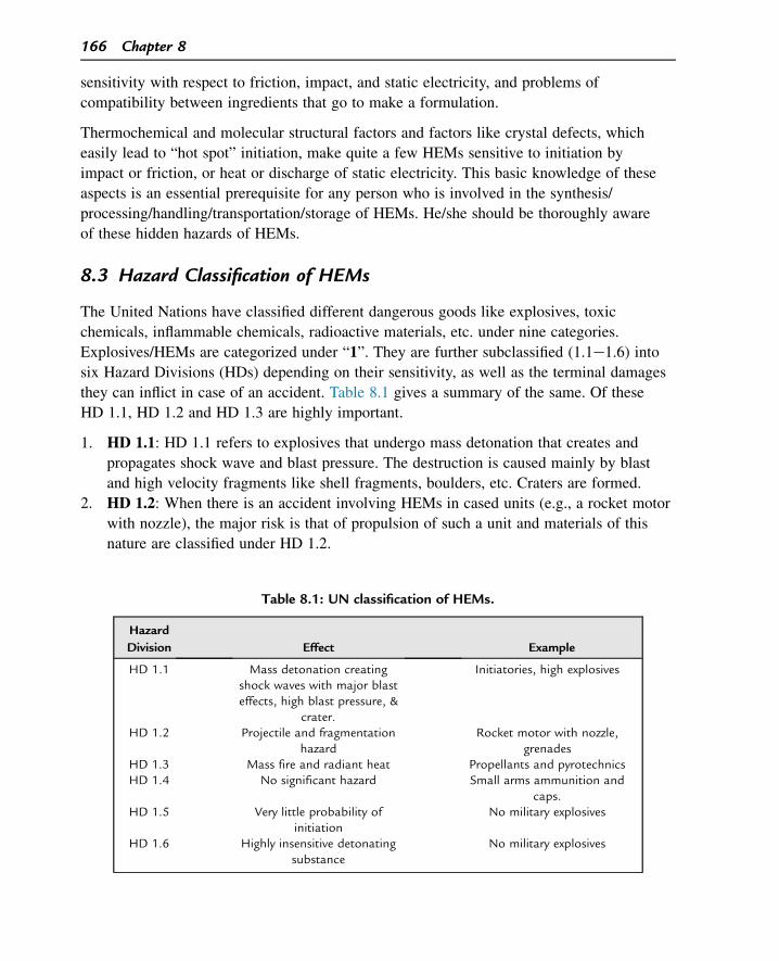
sensitivity with respect to friction, impact, and static electricity, and problems of
compatibility between ingredients that go to make a formulation.
Thermochemical and molecular structural factors and factors like crystal defects, which
easily lead to “hot spot” initiation, make quite a few HEMs sensitive to initiation by
impact or friction, or heat or discharge of static electricity. This basic knowledge of these
aspects is an essential prerequisite for any person who is involved in the synthesis/
processing/handling/transportation/storage of HEMs. He/she should be thoroughly aware
of these hidden hazards of HEMs.
8.3 Hazard Classification of HEMs
The United Nations have classified different dangerous goods like explosives, toxic
chemicals, inflammable chemicals, radioactive materials, etc. under nine categories.
Explosives/HEMs are categorized under “1”. They are further subclassified (1.1e1.6) into
six Hazard Divisions (HDs) depending on their sensitivity, as well as the terminal damages
they can inflict in case of an accident. Table 8.1 gives a summary of the same. Of these
HD 1.1, HD 1.2 and HD 1.3 are highly important.
1. HD 1.1: HD 1.1 refers to explosives that undergo mass detonation that creates and
propagates shock wave and blast pressure. The destruction is caused mainly by blast
and high velocity fragments like shell fragments, boulders, etc. Craters are formed.
2. HD 1.2: When there is an accident involving HEMs in cased units (e.g., a rocket motor
with nozzle), the major risk is that of propulsion of such a unit and materials of this
nature are classified under HD 1.2.
Table 8.1: UN classification of HEMs.
Hazard
Division Effect Example
HD 1.1 Mass detonation creatingshock waves with major blasteffects, high blast pressure, &
crater.
Initiatories, high explosives
HD 1.2 Projectile and fragmentationhazard
Rocket motor with nozzle,grenades
HD 1.3 Mass fire and radiant heat Propellants and pyrotechnicsHD 1.4 No significant hazard Small arms ammunition and
caps.HD 1.5 Very little probability of
initiationNo military explosives
HD 1.6 Highly insensitive detonatingsubstance
No military explosives
166 Chapter 8
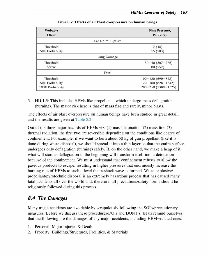
3. HD 1.3: This includes HEMs like propellants, which undergo mass deflagration
(burning). The major risk here is that of mass fire and rarely, minor blasts.
The effects of air blast overpressure on human beings have been studied in great detail,
and the results are given at Table 8.2.
Out of the three major hazards of HEMs viz. (1) mass detonation, (2) mass fire, (3)
thermal radiation, the first two are reversible depending on the conditions like degree of
confinement. For example, if we want to burn about 50 kg of gun propellant (like it is
done during waste disposal), we should spread it into a thin layer so that the entire surface
undergoes only deflagration (burning) safely. If, on the other hand, we make a heap of it,
what will start as deflagration in the beginning will transform itself into a detonation
because of the confinement. We must understand that confinement refuses to allow the
gaseous products to escape, resulting in higher pressures that enormously increase the
burning rate of HEMs to such a level that a shock wave is formed. Waste explosive/
propellant/pyrotechnic disposal is an extremely hazardous process that has caused many
fatal accidents all over the world and, therefore, all precautions/safety norms should be
religiously followed during this process.
8.4 The Damages
Many tragic accidents are avoidable by scrupulously following the SOPs/precautionary
measures. Before we discuss these procedures/DO’s and DONT’s, let us remind ourselves
that the following are the damages of any major accidents, including HEMerelated ones.
1. Personal: Major injuries & Death
2. Property: Buildings/Structures, Facilities, & Materials
Table 8.2: Effects of air blast overpressure on human beings.
Probable
Effect
Blast Pressure,
Psi (kPa)
Ear Drum Rupture
Threshold 7 (48)50% Probability 15 (103)
Lung Damage
Threshold 30e40 (207e276)Severe 80 (552)
Fatal
Threshold 100e120 (690e828)50% Probability 120e180 (828e1242)100% Probability 200e250 (1380e1725)
HEMs: Concerns of Safety 167

3. Morale of Workers
4. Downtime
5. Reputation (of the establishment)
8.5 General Safety Directives
If you are working in the field of HEMs, please pay attention to EACH and EVERY
point given below.
8.5.1 Assume the Hazard
“Expect the unexpected,” particularly while you will work with new materials/
compositions.
8.5.2 Never Work Alone!
Work as a group, even if it is a small one.
8.5.3 Start with the Smallest Possible Quantities
Particularly while the compound/composition is expected to be sensitive, e.g., initiatory
composition. What should be that “smallest possible quantity” can be decided after
thorough discussion with the Safety Division of the establishment.
8.5.4 Safety Shields
Use safety shieldsdwherever needed.
8.5.5 Fire Hazards: Expect and be Ready
Expect fire hazards and keep your Fire Fighting equipments in readiness.
8.5.6 Ground (Earth) Your Facilities
Grounding/earthing the personnel and equipments is an inescapable requirement when one
deals with sensitive HEMs like initiatories and pyrotechnics. In fact, handling propellants
(for guns, rockets, etc.) during dry weather also strictly calls for grounding both the
working personnel and equipments.
The static electricity discharge pits connected to the equipments should be periodically
inspected for their reliability as also the reliability of other static electricity discharge/
conducting mats, gloves, and garments.
168 Chapter 8
8.5.7 Wear Protective Garments/Equipments (Including Antistatic Ones)
These include gas masks/goggles/helmets/aprons/safety shoes/antistatic shoes, etc.,
depending on the type of operation involved.
8.5.8 Practice Relative Humidity Control
When processing/handling explosives, propellants, and pyrotechnics, which are sensitive to
static discharge, the Relative Humidity in the process room/laboratory should not be less
than 60%. The process rooms should be equipped with humidifiers for this purpose.
8.5.9 Housekeeping
Good housekeeping greatly helps to avoid accidents. Ensure that the labs/process rooms are not
cluttered with too many equipments/hardware/materials. Avoid storing incompatible materials
together. Ensure before the commencement of operation that the exit pathway is clear.
8.5.10 Know about the Material Hazards
The hazardous nature of materials should be well understood by all the concerned
workers/operators. Do thorough literature survey to know such hazards before new
processes are tried. (Examples):
1. Chlorates are highly incompatible with carbonaceous matter, ammonium compounds,
sulphur, red phosphorus, etc.
2. Water is dangerous with mixtures containing powdered Zr/Ti/Mg/Zn/Al.
3. Very fine ammonium perchlorate/ammonium nitrate can be dangerously sensitive to
impact in presence of carbonaceous impurities.
8.5.11 Toxic Hazards
It should be realized that many HEMs and their related chemicals possess not only
explosion and fire risks but also toxic hazards. For example, prolonged contact with RDX
and trinitrotoluene (TNT) is known to cause skin-related ailments. Isocyanates (like
toluene di-isocyanate (TDI) used in composite propellant processing) can cause lungs-
related problems like bronchitis. Prolonged ingestion of solvents like benzene might
cause cancer while heavy metal ions of barium, and lead might severely impair the
functioning of liver and kidneys. Therefore, the following preventive measures have to be
taken:
• Compulsory use of personnel protective equipments like gas masks, gloves, aprons, etc.,
as required
HEMs: Concerns of Safety 169
• Periodic workplace monitoring for toxic fumes with reference to the Threshold Limiting
Values (TLV)/Short Term Exposure Limit values for the particular chemical
• Effluent treatment if needed
8.5.12 Prepare a Work Plan
• In case of an established process, ensure that Standard Operating Procedure (SOP) has
been prepared, taking care of all safety aspects including Man Limit, Explosive Limit,
Fire-fighting facilities, Housekeeping, Earthing, etc.
• In case of a new process/synthesis of new HEM, do a thorough literature survey to
gauge the hazards involved and then make a step-by-step procedure with precautions to
be observed to prevent any runaway reactions/fire/explosion.
8.5.13 Hazard Evaluation
While preparing/processing new explosives/formulations:
1. Start with the smallest quantity.
2. Soon after the initial preparation, evaluate its sensitivity/stability by various tests like
Impact sensitivity, Friction sensitivity, Spark sensitivity, differential thermal analysis
(DTA), Vacuum stability, etc.
3. In case of new mixtures, first evaluate the compatibility between various ingredients
using techniques like DTA.
The results of these tests will adequately caution you before you do further processing/
scaling up.
8.5.14 Storage/Transport
During storage/transport of explosives, due care should be taken to observe the statutory
explosive regulations very meticulously. While planning an explosives process building or
magazine, various safety distances like Storage Inside Quantity Distance (SIQD), Process
Inside Quantity Distance (PIQD), and Outside Quantity Distance (OQD) should be strictly
followed apart from the type of protection necessary like the requirement of a particular
type of traverse, blast wall, etc. Both during storage and transport of explosives, care
should be taken to ensure that:
• only the approved type of package and transport like explosive van should be used.
• no incompatible groups of explosives are transported together.
Note: Extensive studies and trials have been carried out to decide upon the
QuantityeDistance relation in the field of explosives. For instance, when one wants to
construct a magazine, an Explosive Storage House (ESH) for storing 2 tons of RDX
170 Chapter 8
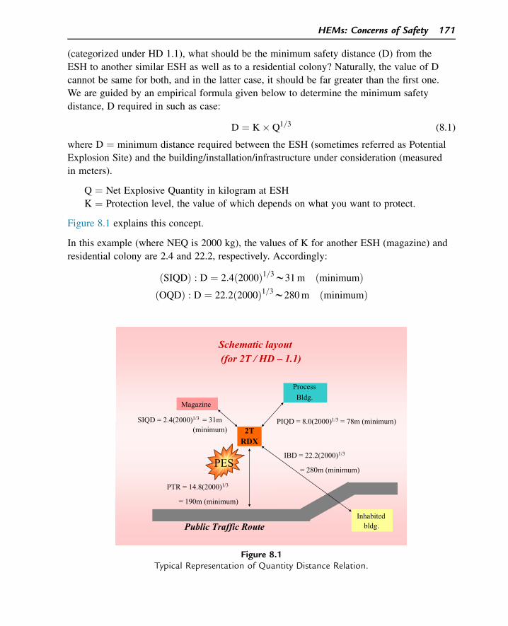
(categorized under HD 1.1), what should be the minimum safety distance (D) from the
ESH to another similar ESH as well as to a residential colony? Naturally, the value of D
cannot be same for both, and in the latter case, it should be far greater than the first one.
We are guided by an empirical formula given below to determine the minimum safety
distance, D required in such as case:
D ¼ K� Q1=3 (8.1)
where D ¼ minimum distance required between the ESH (sometimes referred as Potential
Explosion Site) and the building/installation/infrastructure under consideration (measured
in meters).
Q ¼ Net Explosive Quantity in kilogram at ESH
K ¼ Protection level, the value of which depends on what you want to protect.
Figure 8.1 explains this concept.
In this example (where NEQ is 2000 kg), the values of K for another ESH (magazine) and
residential colony are 2.4 and 22.2, respectively. Accordingly:
ðSIQDÞ : D ¼ 2:4ð2000Þ1=3w31m ðminimumÞðOQDÞ : D ¼ 22:2ð2000Þ1=3w280m ðminimumÞ
PIQD = 8.0(2000)1/3 = 78m (minimum)
PES
Magazine
ProcessBldg.
PTR = 14.8(2000)1/3
= 190m (minimum)
SIQD = 2.4(2000)1/3 = 31m(minimum)
Public Traffic Route
Schematic layout(for 2T / HD – 1.1)
2TRDX
Inhabited bldg.
IBD = 22.2(2000)1/3
= 280m (minimum)
Figure 8.1Typical Representation of Quantity Distance Relation.
HEMs: Concerns of Safety 171
It means that there is a nine-fold increase in the minimum (safety) distance when we
compare a residential colony with another ESH.
8.5.15 Waste Disposal
Although it may appear innocuous and routine, waste disposal of explosives, propellants,
and pyrotechnics is probably one of the most hazardous operations in the field of
explosives. As already mentioned earlier, many fatal accidents have been well-reported
during the waste disposal of explosives and ammunitions. Their disposal should be well
planned and carried out strictly as per the laid down norms available in the literature.
8.6 Conclusion
As it is normally described about fire and electricity, explosives are our “best friend but
also our worst enemy.” Remember that when we talk about safety:
• Ignorance cannot be excused
• Negligence cannot be tolerated
• Overconfidence cannot be pardoned
Suggested Reading
[1] R.M. Downey, Explosives Safety Standards: Safety, United States, Department of the Air Force,Headquarters US Air Force, 1992.
[2] DoD, Ammunition and Explosives Safety Standards, Defense Technical Information Center, 1978.[3] DOE Explosives Safety Manual, Manual HSdOffice of Health, Safety and Security, January 09, 2006.[4] A. Bailey, S.G. Murray, Explosives, Propellants, and Pyrotechnics, Pergamon Press, Oxford, New York,
1988.[5] Service Textbook of Explosives, Ministry of Defence, Publication, UK, 1972.[6] P.W. Cooper, Explosives Engineering, VCH, Publishers Inc, USA, 1996.[7] J. Akhavan, The Chemistry of Explosives, third ed., Royal Society of Chemistry, 2011.
Questions
1. What are the different hazard classifications of HEMs?
2. What is SOP? How it is important for new processes?
3. What are the different classes of fire extinguishers available?
4. How are thermal techniques useful towards explosives safety?
5. What are the steps necessary to prevent electrostatic initiation of HEMs?
6. Why are waste propellants disposed by spreading them as a thin layer?
172 Chapter 8

CHAPTER 9
HEMs: Concerns of Security
9.1 HEMs: Concerns of Security
Palpably, terrorism is the number one menace and threat to global peace today. The most
common tools that the terrorists use today are high explosives, although the world should
be ready to prevent and combat terrorism based on more disastrous tools like nuclear,
biological, and chemical weapons. The very survival of humanity today depends on the
human will, technological advancement, and judicious strategies in this direction.
We are witnesses to the use of high explosives in terrorist attacks in versatile ways right
from the crude lumps containing simple mixture of ammonium nitrate and nails
(intended to be high-velocity projectiles on the initiation of AN) and a detonator to
sophisticated, remote-operated explosive devices. When the terrorists fail to get stolen
ammunition or relatively costly and strategic explosives like RDX, the option of easily
accessible civil explosives (mostly AN-based and some times NG/dynamite-based) is
always open to them. The explosive devices used in unconventional warfare by
terrorists are referred as Improvised Explosive Devices (IEDs) and they can take any
form like letter bombs, pipe bombs, or explosive devices kept in a radio transistor/
suitcases/lunch boxes/toys, etc. Some of the commonly used explosives in IEDs are
given in Table 9.1.
The use of innocuous materials as explosives for terrorist activity is a cause of worry.
Recent approaches to use CHO materials (free from nitro and nitrato groups to escape
detection) are an alarming trend. For example, it is reported that triacetone triperoxide
(TATP) was about to be used in the terrorist attempt foiled a few years back in London. It
was intended to blast the aircrafts in midair. It can be obtained in crude state from polish
remover. Hexamethylene triperoxide diamine (HMTD) is another compound of this class,
which was captured from Algerian terrorists entering into the United States from Canada.
OO
OO
O
O
CH3
CH3
CH3
CH3
H3C
H3C
TATP
Demystifying Explosives: Concepts in High Energy Materials. http://dx.doi.org/10.1016/B978-0-12-801576-6.00009-4
Copyright © 2015 Elsevier Inc. All rights reserved. 173
N
CH2
CH2
CH2
O
O
O O
O
O CH2
CH2
CH2
N
HMTD
9.2 Detection of Explosives
The detection of hidden explosives and prevention of a disaster is one of the major
technological challenges today. Although a huge amount of work has been and is being
done in this direction, different devices designed and manufactured for this purpose have
their own advantages and disadvantages. One of the earliest methods adopted was to make
it a statutory obligation on the part of an explosives manufacturer to add certain chemicals
Table 9.1: Some improvised explosive devices (IED) compositions.
Conventional/Military
Explosives used in IEDs
Commercial Explosives
used in IEDs
RDX-based IEDs Ammonium nitrateebasedIEDs
SEMTEX(RDX, styrene-butadiene
copolymer & additives (plasticexplosive used in 1988 Pan Am
aircraft blast))SEMTEX-H
(RDX, PETN, styrene-butadienecopolymer, motor oil, &
additivesC-2: RDX, TNT, DNT,a
MNT, & NCC-3: RDX, TNT, DNT,
Tetryl, & NCC-4: RDX, Polyisobutylene, &
Fuel oil)
Red diamond: Ammoniumnitrate, Sodium nitrate,
Nitroglycerine, & additivesANFO: Ammonium nitrate &
fuel oilPrillex: Ammonium nitrate &
diesel oilSigmagel Titagel: Ammoniumnitrate, Sodium nitrate, &
Calcium nitrateLovex: Ammonium nitrate,mono-methyl ammoniumnitrate, & gelling agentEmulsion explosives
Nipak: Ammonium nitrate,Sodium nitrate, polyurethane,
& additivesTNT based IEDs
Cyclotol: RDX & TNTTetryol: TNT & Tetryl
MiscellaneousPetrogel: Nitroglycerin,
Ethylene Glycol Dinitrate,Nitrocellulose, sodium nitrate,
& additivesDynamite: NG þ Keiselgur
Slurry and water gel explosives
PETN based IEDsDetsheet: PETN & Plasticizer
Pentolite: PETN & TNT
aDNT, Dinitro toluene.
174 Chapter 9

in a small percentage to the explosives at the time of processing. The said chemicals
(called taggants) have a low vapor pressure, but their vapors are easily detectable by
devices such as Electron Capture Detector (ECD). However, if the IED is thoroughly
sealed, hardly allowing any vapor of that chemical to effuse out, this method will be of no
use. Some such taggant chemicals are given below:
C C CH3H3C
CH3 CH3
NO2 NO2
H2C
H2C O
O NO2
NO2
NO2
CH3
NO2
CH3
2,3-Dimethyl-2,3-dinitrobutane Ethylene glycol dinitrate Ortho mononitro toluene para mononitro toluene
(Note: Most of the explosives themselves have very low vapor pressures. For example, the
vapor pressures of RDX and PETN (in mm of Hg at 25 �C) are 8.0 � 10�8 and
7.0 � 10�9, respectively. In case these explosives are embedded in a polymeric matrix as a
plastic explosive, the vapor emission will go down further drastically).
In the detection of explosives, sniffer dogs have application since as long as mobile
detectors have been around. It is reported that they have about 90% reliability. However,
major problems are their deployment in public places, need for continuous training, and
proper handlers. Law enforcing agencies are increasingly dependent on conventional X-ray
detectors at entry points like airports, seaports, and other important public places.
Although such heavy X-ray detectors have been doing a good job in scanning the
baggages to detect any explosive devices, their immobility limits their use in detecting
hidden explosives elsewhere. At times, it may be required to detect hidden explosive at a
stand-off distance in view point of safety. For such purposes, stand-off detectors are
designed to detect explosives at a distance of 10 m or more. Different devices have been
and are still being developed for the purpose of detection of explosives, and each of them
is based on a specific principle such as electron capture (Electron capture detector (ECD)),
chemiluminescence (CL Detector), ion mobility (Ion mobility spectrometer (IMS)),
diamagnetism of materials, fast neutron activation, etc., and a few of them are described
below:
9.2.1 Electron Capture Detector
Principle: It records changes in current due to absorption of electrons by certain electron-
absorbing groups (e.g., NO2) present in explosives molecules. The ECD is used for
detecting electron-absorbing components of high electronegativity such as halogenated
compounds in the output stream of a gas chromatograph.
HEMs: Concerns of Security 175
9.2.2 Ion Mobility Spectrometer
Principle: It records the mobility of the explosive molecular ions that is characteristic of
an explosive. IMS is a spectrometry technique capable of detecting very low
concentrations of chemicals based upon the differential migration of gas phase ions
through a homogeneous electric field.
9.2.3 Thermoredox Detector
Principle: It records the electrochemical reduction of �NO2 group present in the
explosives. This technology is based on decomposition of explosive substance followed by
the reduction of the NO2 groups.
Advantages Disadvantages
Highly selective Only usable for a fewconstituents
High sensitivity (<1 pgdetection limit)
Radioactive detectoris used
Nondestructive Smaller linear range &response factors vary
considerably
Advantages Disadvantages
Detects the presence orabsence of an energeticmaterial in seconds
Low resolution
(Can detect quantitiesfrom 0.1 to
10 nanograms)
Susceptible toatmospheric changes
Advantages Disadvantages
This technique does not require acarrier gas other than ambient air
Sensitivity isfairly low
System is portable, lightweight,and powered by rechargeable
batteries
Harmless nitrocompounds often create
false alarmsLow consumable cost, requiresvery limited operator training,
and user friendly
Suitable only forcompounds with high
vapor pressure
176 Chapter 9
9.2.4 Field Ion Spectrometer
Principle: The principle is based on filtering ion species according to the functional
dependence of their mobilities with electric field strength.
Field ion spectrometer, also known as transverse field compensation IMS, is a new
technique for trace gas analysis that can be applied to the detection of explosives and
narcotics. It eliminates the gating electrodes needed in conventional IMS to pulse ions into
the spectrometer; instead, ions are injected into the spectrometer and reach the detector
continuously, resulting in improved sensitivity. The technique enables analyses that are
difficult with conventional, constant field-strength IMS.
9.2.5 Diamagnetism-Based Magnetic Field Detector
Principle: The detection is based on the principle that every material has a characteristic
magnetic property and can be detected accordingly.
Magnetometers have a wide range of potential applications, and where there is an
electrical current, there is a magnetic field. Measurements of magnetic fields can reveal
information about the electrical activity, the chemical identity of a spinning atom, or
simply the presence or absence of metal. This consists of a laser, a cell containing
vaporized metal atoms, and a light detector. When the metal atoms are illuminated by the
laser, they align such that they don’t absorb any of the light. The presence of even a very
weak magnetic field, however, disrupts their alignment, and they absorb some of the light.
This change is recorded by the detector.
With small size and sensitivity, the new sensors promise to improve detection of bombs
and could be incorporated into future magnetic resonance imaging (MRI) scanners. It is
small and cheap, and uses very little power. For the detection of IED or unexploded
ordnance in minefields, the small size and low power consumption of the sensors could
make a big difference. The sensors could be grouped in arrays, making it possible to gain
more data in a given amount of time.
9.2.6 Nuclear Quadrupole Resonance Detector
Nuclear Quadrupole Resonance (NQR) is a sensor technology related to nuclear magnetic
resonance (NMR). Any nucleus with more than one unpaired nuclear particle (protons or
neutrons) will have a charge distribution that results in an electric quadrupole moment.
NQR measures a signature unique to the explosive contained in the hidden objects, thus
providing a means of efficiently detecting land mines.
HEMs: Concerns of Security 177
NQR can detect even small quantities of explosives. NQR signature is independent of the
shape of the explosive. The signature emanates directly from the condensed phase, and
NQR does not have the shortcomings that plague vapor-phase chemical detectors. It
provides the chemical specificity of NMR and the volume capacity of MRI without the
need for expensive and cumbersome DC magnets.
9.2.7 Micro Electro Mechanical Systems
Micro Electro Mechanical Systems (MEMs) is a recent technology and it consists of
integrated mechanical elements, sensors, actuators, and electronics on a silicon substrate
using a process technology called microfabrication. The sensors gather information by
measuring mechanical, thermal, biological, chemical, magnetic, and optical signals from
the environment. The microelectronic integrated circuits (ICs) act as the decision-making
piece of the system by processing the information given by the sensors. Finally, the
actuators help the system respond by moving, pumping, filtering, or somehow controlling
the surrounding environment to achieve its purpose. Research and development efforts are
in progress to develop a viable and general purpose explosives detection system based on
MEMs.
A number of explosive vapor detection devices based on other spectroscopic techniques
like photoluminescence, Resonance enhanced multi-photo ionization, Cavity ring down
spectroscopy, Laser induced breakdown spectroscopy, Raman Scattering and Laser
imaging detection and ranging, etc., are emerging on the scene. The technologies receiving
major attention are described below.
1. Biosensors
2. Surface Acoustic Wave
3. Micro cantileverebased mine detection system
4. Amplifying fluorescent polymers
5. Detector-based on diamagnetism
During recent times, the miniaturization of analytical instruments has resulted in the
availability of UVeVIS, Near infra red (IR), fluorescence, Raman spectrophotometers for
field applications. The literature reports also indicate that the miniaturization of mass
spectrometers has also been mastered and they may become available in near future for
field analysis.
The trace explosive detectors require the operator to approach the IED to close distances,
of the order of a few centimeters, unless some robot or unmanned ground/aerial vehicle is
employed. The detection of an IED in large area like residential area or ground/stadium
becomes a laborious and time-consuming task.
178 Chapter 9
In view of the unabated use of different explosives by terrorists with varying degrees of
innovation and sophistication, huge sums of money are being spent toward the
development of detectors with better accuracy and reliability, portability, very low
probability of setting false alarms, and safety features.
Suggested Reading
[1] J. Yinon, Forensic and Environmental Detection of Explosives, John Wiley & Sons, Inc, 1999.[2] M. Marshall, J.C. Oxley, Aspects of Explosives Detection, first ed., Elsevier Science, 2011.[3] J. Yinon, Counterterrorist Detection Techniques of Explosives, Elsevier, 2007.[4] J. Gardner, Y.J. Jehuda, Electronic noses and sensors for the detection of explosives, in: Proceedings of
the NATO Advanced Research Workshop, Held in Warwick, Coventry, U.K, 2003.[5] J. Gardner, Y. Jehuda, Electronic Noses and Sensors for the Detection of ExplosiveseNATO Science
Series II, 2004. New York.[6] H. Schubert, A. Kuznetsov, Detection of explosives and landmines methods and field experiences methods
and field experience, in: Proceedings of the NATO Advanced Research Workshop, Petersburg, Russia,2001.
[7] H. Schubert, A. Kuznetsov, Detection and disposal of improvised explosives, in: Proceedings of the NATOAdvanced Research Workshop on Detection and Disposal of Improvised Explosives St. Petersburg, Russia,2005.
[8] H. Schubert, A. Kuznetsov, Detection of liquid explosives and flammable agents in connection withterrorism, in: Proceedings of the NATO Advanced Research Workshop on Detection of Liquid Explosivesand Flammable Agents in Connection with Terrorism, NATO Science for Peace and Security Series B,Petersburg, Russia, 2007.
Questions
1. What is meant by IEDs?
2. Why are IEDs difficult to be detected?
3. What are taggants? Name any two taggants used for military explosives.
4. How does an ECD work?
5. What are MEMs? How are they fabricated?
6. Are there any common methods of detection of explosives?
HEMs: Concerns of Security 179

This page intentionally left blank
CHAPTER 10
HEMs: Characterization and Evaluation
10.1 Introduction
In any research area concerned with new chemical compounds, characterization and
evaluation of the synthesized compounds, including intermediates, are of vital importance.
High-energy materials (HEMs) cannot be an exception. Characterization is essentially an
identification process whereas evaluation refers to the measurement of certain special
characteristics of the synthesized compounds. For instance, a newly synthesized energetic
compound is “characterized” by a systematic process involving chromatography (to ensure
the purity of the compound), spectroscopy, and any such method to make sure of its
molecular structure so that the chemist knows what exact compound he has synthesized.
On the other hand, the chemist would “evaluate” the new compound for certain specific
performance parameters or performance potentials. For example, a newly synthesized
explosive molecular compound may be evaluated for calorimetric value (thermochemical
potentials), velocity of detonation (VOD; detonation potential), or friction/impact
sensitivity figures (mechanical sensitivity potential).
With the advent of highly sophisticated instrumental analytical techniques, the
characterization and evaluation techniques related to HEMs have come a long way over
the years. Chromatography, spectroscopy, and thermal analysis techniques are the mainstay
for characterization and evaluation of HEMs. It might be interesting to note that certain
techniques that are as old as a century or several decades are still being followed today
when it comes to the evaluation of certain characteristics of HEMs. The vacuum stability
test for explosives and certain propellants, friction and impact sensitivity tests for almost
all HEMs, and shock sensitivity tests for explosives may look a little archaic or even
outdated; however, all of these tests are time-tested, highly reliable, and totally
indispensable. Apart from these, there may be highly specific tests for a particular
explosive. For instance, for nitrocellulose (NC), the Bergmann and Junk test chemically
measures the amount of oxides of nitrogen evolved on heating a gram weight of NC for a
specific period at a specific temperature. The amount of oxides of nitrogen evolved
(evaluated titrimetrically) indicates the extent of instability of NC. This chapter does not
include such tests, but it gives a general approach to the characterization and evaluation of
HEMs.
Demystifying Explosives: Concepts in High Energy Materials. http://dx.doi.org/10.1016/B978-0-12-801576-6.00010-0
Copyright © 2015 Elsevier Inc. All rights reserved. 181
10.2 Chromatographic Techniques
Chromatographic techniques are a group of analytical techniques used for the separation
of components from a mixture using differences in their distribution between two phases
(stationary and mobile phase). Many chromatography techniques are available today for
characterization purposes (e.g., thin layer chromatography (TLC), gas chromatography
(GC), high-performance liquid chromatography (HPLC) etc.). These techniques are used
for identification, separation, characterization, and quantification. Let us discuss only the
techniques that are frequently used for the characterization of energetic materials.
10.2.1 Thin Layer Chromatography
TLC is a quick, simple, ready-to-use, inexpensive tool typically used in laboratory
synthesis practices. It gives the quick answer to the synthesis chemist whether he/she is
going in the correct direction or not. This is usually not considered a characterization
technique, but it gives an idea about the number of components in a reaction mixture.
TLC is used to confirm the presence of unknown substances in comparison to the standard
known substance using the relative front (Rf), which is the ratio of the distance traveled by
the solvent front to the distance traveled by the substance under examination. TLC is also
used to monitor the course of the reaction and gives an idea about the conversion of
reactant to product. TLC experiments are generally performed with reactant, product, and
possible byproduct in a single run.
A TLC plate is a thin sheet of solid adsorbent (usually silica or alumina) spotted with
known and unknown substances. This plate is eluted with a proper solvent (often binary
mixtures based on the polarity) liquid. Once the solvent reaches the top of the plate, the
plate is removed from the developing chamber, dried, and the separated components of the
mixture are visualized in an ultraviolet (UV) lamp. Identical compounds possess similar
Rf, and dissimilar compounds deviate up or down.
10.2.2 Gas Chromatography
In GC, the mobile phase is an inert gas and the stationary phase is a liquid or solid. Thus,
in GC, separation of components in a chemical mixture is achieved on the basis of
differences in the partition coefficient of solutes in the gas phase and stationary phase. In
GC, the time gap between the injections of the sample (zero time) and the peak maximum
of substance is called its retention time (RT). It is the characteristic property of the
compound, and it varies from compound to compound. The greater the affinity of
the compound for the stationary phase, the more the compound will be retained by the
chromatographic column and will be eluted later than the one having less affinity for the
stationary phase. The major limitation of GC is that the compound analyzed should
182 Chapter 10
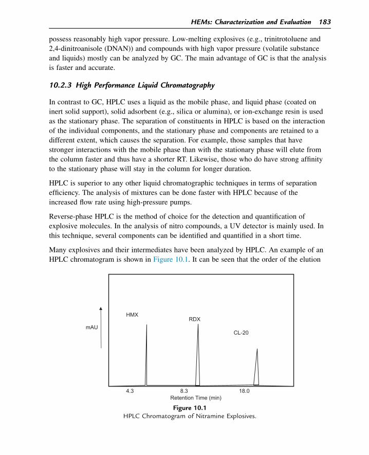
possess reasonably high vapor pressure. Low-melting explosives (e.g., trinitrotoluene and
2,4-dinitroanisole (DNAN)) and compounds with high vapor pressure (volatile substance
and liquids) mostly can be analyzed by GC. The main advantage of GC is that the analysis
is faster and accurate.
10.2.3 High Performance Liquid Chromatography
In contrast to GC, HPLC uses a liquid as the mobile phase, and liquid phase (coated on
inert solid support), solid adsorbent (e.g., silica or alumina), or ion-exchange resin is used
as the stationary phase. The separation of constituents in HPLC is based on the interaction
of the individual components, and the stationary phase and components are retained to a
different extent, which causes the separation. For example, those samples that have
stronger interactions with the mobile phase than with the stationary phase will elute from
the column faster and thus have a shorter RT. Likewise, those who do have strong affinity
to the stationary phase will stay in the column for longer duration.
HPLC is superior to any other liquid chromatographic techniques in terms of separation
efficiency. The analysis of mixtures can be done faster with HPLC because of the
increased flow rate using high-pressure pumps.
Reverse-phase HPLC is the method of choice for the detection and quantification of
explosive molecules. In the analysis of nitro compounds, a UV detector is mainly used. In
this technique, several components can be identified and quantified in a short time.
Many explosives and their intermediates have been analyzed by HPLC. An example of an
HPLC chromatogram is shown in Figure 10.1. It can be seen that the order of the elution
Retention Time (min)
RDXHMX
CL-20 mAU
4.3 18.08.3
Figure 10.1HPLC Chromatogram of Nitramine Explosives.
HEMs: Characterization and Evaluation 183
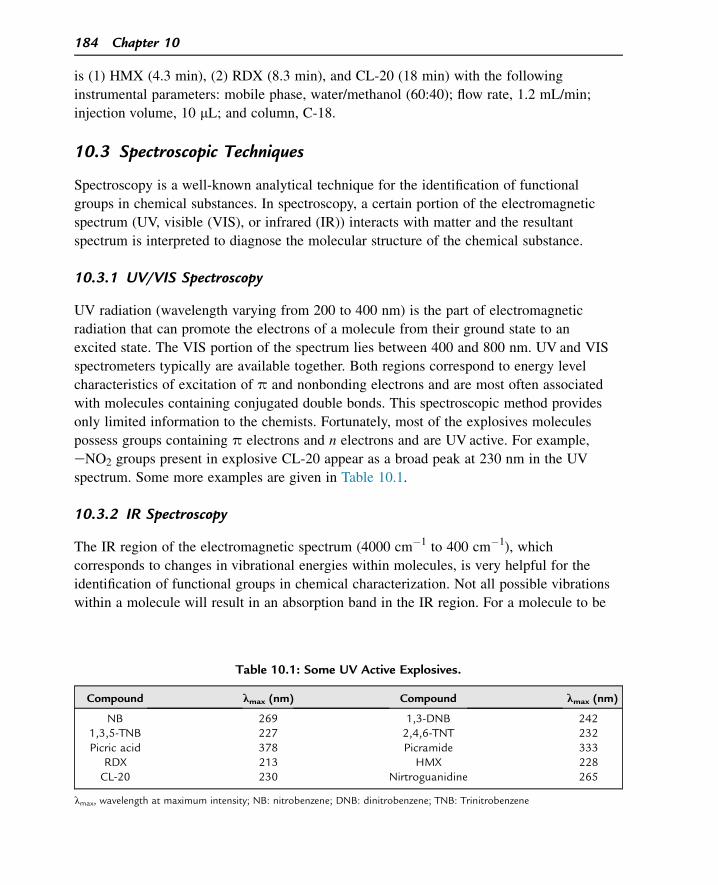
is (1) HMX (4.3 min), (2) RDX (8.3 min), and CL-20 (18 min) with the following
instrumental parameters: mobile phase, water/methanol (60:40); flow rate, 1.2 mL/min;
injection volume, 10 mL; and column, C-18.
10.3 Spectroscopic Techniques
Spectroscopy is a well-known analytical technique for the identification of functional
groups in chemical substances. In spectroscopy, a certain portion of the electromagnetic
spectrum (UV, visible (VIS), or infrared (IR)) interacts with matter and the resultant
spectrum is interpreted to diagnose the molecular structure of the chemical substance.
10.3.1 UV/VIS Spectroscopy
UV radiation (wavelength varying from 200 to 400 nm) is the part of electromagnetic
radiation that can promote the electrons of a molecule from their ground state to an
excited state. The VIS portion of the spectrum lies between 400 and 800 nm. UV and VIS
spectrometers typically are available together. Both regions correspond to energy level
characteristics of excitation of p and nonbonding electrons and are most often associated
with molecules containing conjugated double bonds. This spectroscopic method provides
only limited information to the chemists. Fortunately, most of the explosives molecules
possess groups containing p electrons and n electrons and are UV active. For example,
eNO2 groups present in explosive CL-20 appear as a broad peak at 230 nm in the UV
spectrum. Some more examples are given in Table 10.1.
10.3.2 IR Spectroscopy
The IR region of the electromagnetic spectrum (4000 cm�1 to 400 cm�1), which
corresponds to changes in vibrational energies within molecules, is very helpful for the
identification of functional groups in chemical characterization. Not all possible vibrations
within a molecule will result in an absorption band in the IR region. For a molecule to be
Table 10.1: Some UV Active Explosives.
Compound lmax (nm) Compound lmax (nm)
NB 269 1,3-DNB 2421,3,5-TNB 227 2,4,6-TNT 232Picric acid 378 Picramide 333
RDX 213 HMX 228CL-20 230 Nirtroguanidine 265
lmax, wavelength at maximum intensity; NB: nitrobenzene; DNB: dinitrobenzene; TNB: Trinitrobenzene
184 Chapter 10
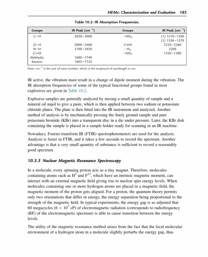
IR active, the vibration must result in a change of dipole moment during the vibration. The
IR absorption frequencies of some of the typical functional groups found in most
explosives are given in Table 10.2.
Explosive samples are generally analyzed by mixing a small quantity of sample and a
mineral oil nujol to give a paste, which is then applied between two sodium or potassium
chloride plates. The plate is then fitted into the IR instrument and analyzed. Another
method of analysis is by mechanically pressing the finely ground sample and pure
potassium bromide (KBr) into a transparent disc in a die under pressure. Later, the KBr disk
containing the sample is placed in a sample holder ready for scanning in an IR machine.
Nowadays, Fourier transform IR (FTIR) spectrophotometers are used for the analysis.
Analysis is faster in FTIR, and it takes a few seconds to record the spectrum. Another
advantage is that a very small quantity of substance is sufficient to record a reasonably
good spectrum.
10.3.3 Nuclear Magnetic Resonance Spectroscopy
In a molecule, every spinning proton acts as a tiny magnet. Therefore, molecules
containing atoms such as H1 and F13, which have an intrinsic magnetic moment, can
interact with an external magnetic field giving rise to nuclear spin energy levels. When
molecules containing one or more hydrogen atoms are placed in a magnetic field, the
magnetic moment of the proton gets aligned. For a proton, the quantum theory permits
only two orientations that differ in energy, the energy separation being proportional to the
strength of the magnetic field. In typical experiments, the energy gap is so adjusted that
60 megacycles (6 � 107 cP) of electromagnetic radiation (corresponds to radiofrequency
(RF) of the electromagnetic spectrum) is able to cause transition between the energy
levels.
The utility of the magnetic resonance method arises from the fact that the local molecular
environment of a hydrogen atom in a molecule slightly perturbs the energy gap, thus
Table 10.2: IR Absorption Frequencies.
Groups IR Peak (cm�1) Groups IR Peak (cm�1)
CeH 2850e3000 eNO2 (1) 1510e1560(2) 1330e1370
OeH 3000e3400 C^N 2220e2260NeH 3100e3450 eN3 2200C]O eNO3 1350e1380
Aldehydic 1680e1740Ketonic 1665e1725
Note: cm�1 is the unit of wave number, which is the reciprocal of wavelength in cm.
HEMs: Characterization and Evaluation 185
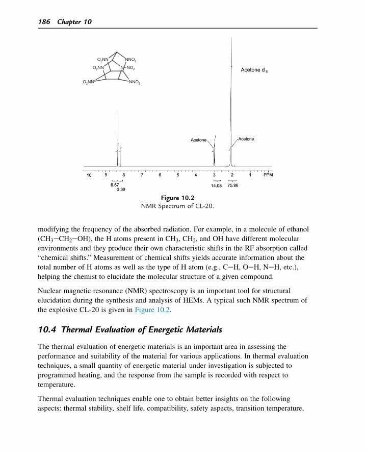
modifying the frequency of the absorbed radiation. For example, in a molecule of ethanol
(CH3eCH2eOH), the H atoms present in CH3, CH2, and OH have different molecular
environments and they produce their own characteristic shifts in the RF absorption called
“chemical shifts.” Measurement of chemical shifts yields accurate information about the
total number of H atoms as well as the type of H atom (e.g., CeH, OeH, NeH, etc.),
helping the chemist to elucidate the molecular structure of a given compound.
Nuclear magnetic resonance (NMR) spectroscopy is an important tool for structural
elucidation during the synthesis and analysis of HEMs. A typical such NMR spectrum of
the explosive CL-20 is given in Figure 10.2.
10.4 Thermal Evaluation of Energetic Materials
The thermal evaluation of energetic materials is an important area in assessing the
performance and suitability of the material for various applications. In thermal evaluation
techniques, a small quantity of energetic material under investigation is subjected to
programmed heating, and the response from the sample is recorded with respect to
temperature.
Thermal evaluation techniques enable one to obtain better insights on the following
aspects: thermal stability, shelf life, compatibility, safety aspects, transition temperature,
O2NN NNO2
O2NN N NO2
NNO2O2NN
Figure 10.2NMR Spectrum of CL-20.
186 Chapter 10
heat capacity, melting temperature, crystallization kinetics, hazard evaluation, aging and
thermal history effects, quality control, dehydration, dehydration kinetics, heat of
transition, phase transition, glass transition, etc. The important techniques generally used
are as follows:
1. Differential thermal analysis (DTA)
2. Differential scanning calorimetry (DSC)
3. Thermogravimetric analysis (TGA)
4. Simultaneous thermal analysis (STA)
10.4.1 Differential Thermal Analysis
DTA is the simplest form of a thermal analysis technique. The principle of DTA is based on
subjecting the sample (e.g., ammonium perchlorate [NH4ClO4, AP]) and an inert reference
material (mostly aluminum oxide) to a simultaneous temperature program and recording the
differential temperature (i.e., difference between the temperature of the sample and that of
the reference, i.e., DT) with respect to the temperature. A few milligrams each of the sample
and reference are taken in separate platinum cups connected to Pt or Pt/Rh temperature
sensors. The entire setup is kept in a heating furnace, and the sample and reference materials
are heated at a specified heating rate (e.g., at 10 �C/min). The difference in temperatures of
sample and reference (DT) is recorded on the ordinate and the temperature (or time, because
the rate of heating is a constant) is recorded on the abscissa.
As long as no reaction (chemical reaction and physical changes such as melting, phase
changes, etc., which involve heat changes) takes place in the sample, DT is zero. If the
sample undergoes an endothermic change (e.g., melting), then its temperature goes lower
than the temperature of the reference and DT is recorded as negative. Conversely, if the
sample undergoes an exothermic reaction (e.g., oxidation), then its temperature will be
higher than that of the inert reference material and DT is recorded as positive. A DTA
thermogram (Figure 10.3) is given for AP and the possible explanations are given (based
on other evidences).
a. DT:�ve; endothermic (240�C) Phase change of AP (orthorhombic to cubic)
b. DT: þve; exothermic (290�C) First stage oxidation of AP
c. DT: þve; exothermic (360�C) Complete oxidation of AP resulting in its deflagration
10.4.2 Differential Scanning Calorimetry
DSC is the most important thermal evaluation technique. In DSC, a known quantity of
sample and a reference are subjected to programmed heating and the difference in energy
inputs into the sample and reference is measured as a function of temperature. The DSC
HEMs: Characterization and Evaluation 187
technique is more quantitative, accurate, and faster than the DTA method. In DSC, the
temperature of the sample and reference is not allowed to vary. For instance, during
simultaneous temperature programming, if the sample undergoes an exothermic reaction,
(thereby becoming hotter than the reference), then the reference is given the heat output
(which can be accurately measured) such that it also attains the temperature of the sample;
conversely, in an endothermic reaction of the sample, heat output is given to the sample.
In a DSC thermogram, the heat output is plotted against the temperature. Figure 10.4
shows the DSC thermograms of ammonium dinitramide (ADN) and CL-20. A DSC
thermogram of ADN shows two endothermic events and one exothermic event. The first
endothermic peak is due to the melting of ADN (92 �C), and the second peak corresponds
to the exothermic decomposition of ADN (150e250 �C with a Tmax of 184�C) to various
decomposition products (mainly ammonium nitrate). Ammonium nitrate formed during the
decomposition sublimes (endothermic peak at 264 �C) in the third step.
CL-20 exists in various polymorphs such as a, b, d, ε, g, etc., but the ε form of CL-20 is
more stable at ambient temperature than other polymorphs. The DSC thermogram of the ε
form of CL-20 shows one small endothermic and a significant exothermic peak
(Figure 10.4(b)). The ε form of CL-20 absorbs heat energy and is transformed into the g
form of CL-20 at 165 �C. This event appears as an endothermic peak. During further
heating, CL-20 exothermically decomposes (onset at 220 �C with a Tmax of 252�C) into
various decomposition products and releases high heat output.
ΔT
Temperature (°C) / Time
~ 240°C (a)
+ve
-ve
0
~ 290°C (b)
~ 360°C (c)
Figure 10.3DTA Thermogram of Ammonium Perchlorate (AP).
188 Chapter 10
DSC study helps an HEM chemist to evaluate the compatibility of ingredients in an
explosive formulation. The compatibility assessment is based on the principle that the
addition of an ingredient (the compatibility of which with the explosive is being assessed)
should not bring down the decomposition temperature of the virgin explosive by more than
5 �C. To conduct the assessment, the DSC thermograms are taken for the main explosive
and for the explosive to which the ingredient is added to the extent required by the
formulation. Let us propose to add either plasticizer A or plasticizer B as 5% of the
formulation to NC (i.e., 95% NC þ 5% plasticizer). The DSC thermograms taken
(Figure 10.5) show that plasticizer A is compatible whereas plasticizer B is not.
10.4.3 Thermogravimetric Analysis
In the TGA thermal evaluation technique, a known quantity of the sample is subjected to
programmed heating, and the weight loss pattern of the sample is measured as a function
HEMs: Characterization & Evaluation
Melting: Endothermic peak
Decomposition: Exothermic peak
Endo
Exo
DSC of Ammonium dinitramide (ADN) ~ 92°C
~ 150°C
~ 184°C
~ 250°C
~ 264°C
Temperature (°C)
Hea
t Flo
w (W
/g)
Sublimation: Endothermic peak
(a)
Endo
Exo
Decomposition: Exothermic peak
Endothermic Solid phase transition (from ε → γ form)
DSC of Hexanitrohexaazaisowurtzitane (CL-20)
~ 165°C
~ 252°C
~ 220°C ~ 280°C
Hea
t Flo
w (W
/g)
Temperature (°C)
(b)
Figure 10.4(a) DSC Thermogram of ADN and (b) DSC Thermogram of CL-20.
HEMs: Characterization and Evaluation 189
of temperature or time. The initial weight of the sample is considered as 100%, and the
loss in weight is recorded as a percentage. As explosives are heated, they lose their weight
through various processes such as dehydration, evaporation, or decomposition. It is
interesting to note that some materials can gain weight by reacting with the atmosphere in
the testing environment. The weight loss data are usually plotted on the y-axis and
temperature/time on the x-axis. Thermogravimetric evaluation of explosives offers
information about the thermal stability of explosives.
TGA of dinitroanisole (DNAN) and N-methyl-2,4,5-trinitroimidazole (MTNI) is depicted
in Figure 10.6. DNAN loses its mass in a single stage in the temperature region of
97e225 �C with a mass loss of 97%. MTNI loses its mass in two stages. In the first stage,
87.5% mass is lost in the temperature region of 105e235 �C, and in the second step
10.5% is lost in the temperature region of 235e320 �C. Apart from obtaining an idea
about the thermal stability of explosives, TGA may help in obtaining insight into the
Demystifying Explosives: Concepts in High Energy Materials
T0 = 165°C
Tmax = 170°C Exo
Endo
Hea
t Flo
w (W
/g)
T0 = 180°C
Tmax = 185°C Exo
Endo
Hea
t Flo
w (W
/g)
Endo
Exo
T0 = 178°C
Tmax = 183°C
Hea
t Flo
w (W
/g)
(a) (b)
(c)
Figure 10.5(a) DSC of NC, (b) DSC of NC þ Plasticizer A (95:5), and (c) DSC of NC þ Plasticizer B (95:5).
190 Chapter 10
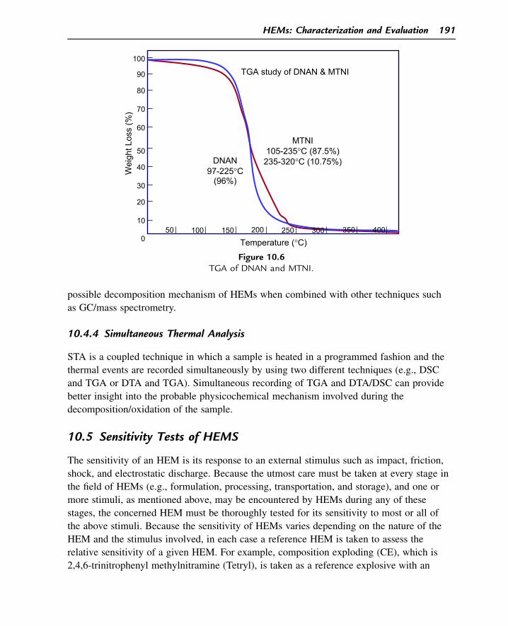
possible decomposition mechanism of HEMs when combined with other techniques such
as GC/mass spectrometry.
10.4.4 Simultaneous Thermal Analysis
STA is a coupled technique in which a sample is heated in a programmed fashion and the
thermal events are recorded simultaneously by using two different techniques (e.g., DSC
and TGA or DTA and TGA). Simultaneous recording of TGA and DTA/DSC can provide
better insight into the probable physicochemical mechanism involved during the
decomposition/oxidation of the sample.
10.5 Sensitivity Tests of HEMS
The sensitivity of an HEM is its response to an external stimulus such as impact, friction,
shock, and electrostatic discharge. Because the utmost care must be taken at every stage in
the field of HEMs (e.g., formulation, processing, transportation, and storage), and one or
more stimuli, as mentioned above, may be encountered by HEMs during any of these
stages, the concerned HEM must be thoroughly tested for its sensitivity to most or all of
the above stimuli. Because the sensitivity of HEMs varies depending on the nature of the
HEM and the stimulus involved, in each case a reference HEM is taken to assess the
relative sensitivity of a given HEM. For example, composition exploding (CE), which is
2,4,6-trinitrophenyl methylnitramine (Tetryl), is taken as a reference explosive with an
Wei
ght L
oss
(%)
Temperature (°C)
TGA study of DNAN & MTNI
50 100 150 200 250 300 350 400
50
100
10
80
40
30
20
90
70
60
DNAN 97-225°C
(96%)
0
MTNI 105-235°C (87.5%) 235-320°C (10.75%)
Figure 10.6TGA of DNAN and MTNI.
HEMs: Characterization and Evaluation 191
impact sensitivity of 70, and, on this scale, the relative impact sensitivity of other
explosives is assessed. A brief mention is made in the following about the various types of
sensitivity tests commonly used in the field of HEMs.
10.5.1 Impact Sensitivity
Impact sensitivity is the ability of a substance to withstand a sudden blow without
decomposing or igniting when impacted by the fall of a 2-kg hammer from a specific
height. A 2-kg weight is released to impact the sample kept on an anvil and the result is
noted. The impact distances are determined, and the results are analyzed by the Bruceton
staircase method. In this method, one measures the 50% initiation level (the height at
which 50% of the samples will detonate), compares it with that of a standard explosive
(CE taken as 70), and reports it as the figure of insensitiveness (F of I). This height is
called the median drop height of the sample.
Figure of Insensitivity of the sample ðF of IÞ ¼ Median dropheight of sample
Median dropheight of reference
� ðF of I of standardÞFor example, if a high explosive and CE (standard) give median drop heights of 60 and
80 cm, respectively, in an experiment, the F of I of the explosive is given as
F of I ¼ 60
80� 70 ¼ 52:5
10.5.2 Friction Sensitivity
Friction sensitivity is the measure of sensitivity to initiation of an HEM to relative
frictional motion between two objects in contact. The sensitivity of an explosive is
determined by subjecting a thin layer of explosive on a predetermined spot to a certain
load through a loading arm and allowing the explosive to undergo standard frictional
movement. The range of load for primary explosives is 10e1000 g and for other
explosives is 0.5e36 kg. The observation of any effects (e.g., smoking, burning, or
exploding) at a minimum particular load is taken as the sensitivity to friction of an
explosive to that load.
10.5.3 Spark Sensitivity
Repeated contact and separation of two dissimilar materials (one of them is insulator
material) lead to accumulation of electric charge, which often gets discharged through
lower potential materials in the surrounding. Hence, it is vital to measure the electrostatic
192 Chapter 10
sensitivity of explosive stores to understand the hazards associated with that particular
material. These data help in designing the safety measures required for reducing the
electrostatic hazards in various operations such as mixing, sieving, handling, storage, etc.
This assessment can be done by exposing a known quantity of a particular sample from
low discharge energy to high discharge energy in an incremental fashion until the sample
gets ignited.
Suggested Reading
[1] J. Yinon, S. Zitrin, Modern Methods and Applications in Analysis of Explosives, John Wiley and Sons,1996.
[2] U. Teipel, Energetic Materials Incorporation of Particular Components with Specialised Properties AllowsOne to Tailor the End Product’s Properties, Wiley-VCH Verlag GmbH, 2004.
[3] W. Kemp, Organic Spectroscopy, second ed., Macmillan, 1987.[4] J.H. Michael, Modern Spectroscopy, fourth ed., Wiley, 2004.[5] J.P. Agrawal, R.D. Hodgson, Organic Chemistry of Explosives, first ed., Wiley, 2007.[6] J. Akhavan, The Chemistry of Explosives, third ed., Royal Society of Chemistry, 2011.
Questions
1. What is the difference between the characterization and evaluation of an HEM? Give an
example.
2. What is the basic principle of chromatography?
3. Why is HPLC a preferred technique in the separation and analysis of HEMs?
4. Why are many HEM molecules active in the UV region?
5. Why do we get three clear, different NMR spectral peaks in ethyl alcohol?
6. Why are thermal analysis techniques very important in the field of HEMs?
7. What is the major difference between DTA and DSC?
8. What are the uses of the TGA technique in the field of HEMs?
9.What are the different types of sensitivity of HEMs and how are they measured?
HEMs: Characterization and Evaluation 193

This page intentionally left blank
CHAPTER 11
HEMs: Trends and Challenges
11.1 Introduction
From the first experiments with gunpowder and fireworks to the latest ultra-powerful high-
explosive, octanitrocubane (ONC), or caged nitramine class of explosives such as CL-20,
man has sought to unleash the force of chemical explosives in more powerful and
controlled ways. However, the rapidly changing technology presents some tremendous
opportunities and pitfalls. Now more than ever, success on the battlefield is dependent on
the rapid access to information and the ability to act on that in a timely manner. The
current trends in the field of high energy materials and the future challenges are discussed
briefly in this chapter.
11.2 Primary Explosives11.2.1 Problems
Mercury fulminate and lead azide are the foremost primary explosives, and they gained
prominence in military ammunitions and civil applications. They ruled the world of
initiatory compounds for more than 70 years. Despite being good in performance, they
suffer from certain inherent drawbacks, such as hydrolytic instability, incompatibility with
copper or its alloys (commonly used for encapsulation of primary explosive formulations),
and high friction sensitivity. Globally, research and development is triggered for the
development of potential primary explosives with figures of insensitivity greater than 20,
which are then less prone to accidental initiation during storage, transport, or handling of
the finished ammunitions and are stable and compatible with copper and its alloys.
11.2.2 Solutions
Lead-free coordination compounds are the choice of tomorrow in view of their additional
advantage of being ecofriendly. Another desirable attribute of this class of compounds is
the presence of almost stoichiometric fuel and oxidizer moieties. These compounds have
been known for some time, but their applications in primary explosives were recently
realized. Two important energetic coordination compounds are nickel hydrazine nitrate
(NHN) and bis-(5-nitro-2H-tetrazolato-N2) tetramine cobalt(III) perchlorate (BNCP).
Demystifying Explosives: Concepts in High Energy Materials. http://dx.doi.org/10.1016/B978-0-12-801576-6.00011-2
Copyright © 2015 Elsevier Inc. All rights reserved. 195
Apart from these, research is focused on the development of energetic coordination
compounds without deleterious metal ions such as Co, Ni, and anions such as ClO�4 and NO�
3 .
11.3 High Explosives
High explosives are the major components of any weapon system. Today, the candidate
molecules available for warhead applications are very limited. Any researcher always
looks for better materials than the existing benchmark candidates. In this regard, any high-
explosive scientists and technologists always look for better materials than HMX.
Three categories of importance under high explosives need to be mentioned here:
1. High-density, high-VOD (velocity of detonation) explosives, which, because of their
superior power (due to high VOD and hence high detonation pressure) and volumetric
efficiency (due to high density), hold great promise to impart enormous lethality to
ammunitions of the future.
2. Insensitive explosives (or low-vulnerability explosives) assume their importance in view
of the safety involved during transportation and storage and to prevent accidental initia-
tion (e.g., due to enemy fire) during a battle. There are often battlefield situations in
which the power of the explosives can be slightly compromised to ensure low vulnera-
bility of the ammunition and avoid any disaster.
3. Thermally stable explosives (sometimes referred as heat-resistant explosives) play a
vital role when a high-temperature environment may adversely affect the performance
(or worse, prematurely initiate) of the explosive. Examples of such an environment are
the explosives filled with warheads of supersonic missiles in which aerodynamic
heating is involved and explosives are used in oil well exploration. Similar to the case
of insensitive explosives, thermal stability is imparted slightly at the cost of the power
of the explosives. As one can expect, imparting all three qualities of high power, high
insensitivity, and high thermal stability in an explosive is impossible. To give an
NiNH2
NH2
NH2NH2
NH2
NH2(NO3)2
NHN
NN
NN NO2
N N
NNO2N
CoH3N NH3
H3N NH3
ClO4
NHN BNCP
196 Chapter 11
example, a certain amount of thermal stability is imparted in an aromatic polynitro
compound by converting one or more eNO2 groups into eNH2 groups (so that inter/
intramolecular hydrogen bonding between eNO2 and eNH2 groups form a sort of a
matrix in the explosive, introducing higher thermal stability). However, sacrificing one
or more energetic eNO2 groups to introduce nonenergetic eNH2 groups results in the
decreased power of the explosive. The choice of 1, 2, or 3 depends on the type of
ammunition in which they are to be used.
11.3.1 High-Density, High-VOD Explosives
The challenges faced by an explosive chemist to achieve their goal of synthesizing an
explosive more powerful (higher VOD) and with higher density are amazingly high. They
must visualize a nonaromatic, polycyclic “caged” compound containing energetic groups
such as eNO2 or NeNO2. Visualization is just the first step; they must assess its
energetics by various empirical and quantum mechanical methods to calculate its expected
VOD and density, if at all it is synthesized. Even if there are a 100 candidate molecules to
start with, the chemist may ultimately end up with a few or even none. This is because
their choices are ruthlessly narrowed down when most (if not all) of the candidates are
rejected in terms of huge costs and hazards because of extreme sensitivity or instability of
the final explosive or even intermediates.
If a new explosive with marginally better properties than HMX is going to be 100 times
costlier than HMX, then no one is going to use it as ammunition. Or, if the same explosive
is very sensitive to mechanical shock or has a poor thermal stability, then it holds no
promise. This is the main reason why new powerful and promising explosives are made
after long intervals of several decades. RDX was first made in the year 1899. Its higher
homolog, HMX, was later made only in the year 1943 after a gap of 44 years.
Under this category, the only two high explosives exceeding the performance of HMX are
hexanitrohexaazaisowurtzitane also called China Lake-20 (CL-20) and ONC. The
synthesis and subsequent manufacture of CL-20 were established only in a few selected
countries. The cost of CL-20 is much higher than that of HMX because it involves quite a
few steps using very costly catalysts. Moreover, its sensitivity to impact and friction is
more than that of RDX and HMX (see Table 11.1). Despite the cost and sensitivity factors,
CL-20 holds great promise in futuristic warheads and its role as an ingredient in low-
signature propellants because of its better oxygen balance than RDX and HMX.
Another interesting candidate in the series is ONC (see Table 11.1). ONC was synthesized
in 1999 using a multistep synthesis approach. No reports appeared in the literature after its
invention because of the difficulties in the preparation methods. Research and development
efforts have to be focused for a viable and simple method for the preparation of ONC.
HEMs: Trends and Challenges 197
Table 11.1: Comparison of RDX, HMX, CL-20, and ONC.
Parameters RDX HMX CL-20 ONC
Structure H2C
N N
H2C CH2
N
NO2
NO2
O2NH2C N
N
H2C N
O2N
CH2
N NO2
CH2
NO2
NO2O2NN NNO2
O2NN N NO2
NNO2O2NN
NO2
NO2
NO2
NO2
O2N
O2N
O2N
NO2
Year first made 1899 1943 1987 1999Density (g/cm3) 1.81 1.91 2.04 2.1
Oxygen balance (%) �21.6 �21.6 �11 0VOD (m/s) 8800 9100 9400 9800
Sensitivity to impact(h50%, cm)
46 38 24 Not reported
Friction (kg) 16 14 8 Not reported
198
Chapter
11
In modern ordnance there is a strong requirement for explosives having thermal stability
and mechanical insensitivity coupled with better explosive performance. Under normal
conditions of use, munitions filled with conventional explosives are safe and effective to
provide desired military capability. However, they violently respond to unintentional
initiation such as getting exposed to enemy fire. In general, high explosives, gun
propellants, and rocket propellants are sensitive to heat, mechanical shock, fire, and
mechanical impact by bullets or fragments. Such secondary effects may lead to the violent
initiation of the ammunitions and result in huge loss of men and materials on a battlefield.
11.3.2 Insensitive High Explosives
To avoid this kind of collateral damage to weapons, a new concept called “insensitive
munitions” (IMs) has emerged. IMs are munitions designed to minimize the consequences
of an accidental initiation without compromising the expected performance. IMs are
designed such that they are difficult to be ignited accidentally or, in the case of an
accidental initiation, it does not result in any detonation or mass fire.
The synthesis of nitrotriazoles as insensitive energetic materials has received a great deal
of attention in the past 20 years. The most studied nitrotriazole explosive is 3-nitro-
1,2,4-triazole-5-one (NTO). NTO is currently being widely investigated in main charge
warhead filling for IMs. It is used in cast-cured, pressed, and sheet explosive formulations.
Another new insensitive energetic material with promising properties is 1,1-diamino-
2,2-dinitroethylene (FOX-7). In recent years, much interest has been devoted to RDX in
another form (i.e., reduced sensitivity RDX (RSRDX) or insensitive RDX), which, when
incorporated in cast-cured plastic-bonded explosive formulation, can confer reduced shock
sensitivity as measured through the gap test. RSRDX is reported to possess improved
crystal density and fewer crystal defects with smooth surface morphology, and these
factors seem to reduce the mechanical sensitivity of RDX. These features also impart
reduced vulnerability toward shock initiation. The preparation method of RSRDX is not
disclosed in open literature because of its strategic importance. The properties of some of
the insensitive explosives are given in Table 11.2 in comparison with some thermally
stable explosives.
11.3.2.1 Is TNT Suitable for IM?
In the area of melt-cast explosives, trinitrotoluene (TNT) is the well-known explosive used
in all possible ammunitions since World War I. The advantage of TNT is that it melts at
81 �C and can be cast alone or in combination with other ingredients such as RDX,
aluminum, and ammonium perchlorate (AP) into various desired shapes. Although the
performance is lower, TNT was well accepted by ordnance communities because of the
above advantages. However, TNT and TNT-based ammunitions pose long-term health
HEMs: Trends and Challenges 199
Table 11.2: Performance comparison of insensitive and thermally stable explosives.
Name
of HEM Structure
Oxygen
Balance
(%)
Density
(g/cm3)
VOD
(m/s)
Impact
Insensitivity
(h50%, cm)
Friction
Insensitivity
(kg)
Insensitive High Explosives
NTO
N
H
C
N
N
C
NO2H
O
�24.6 1.93 8564 93 >36
FOX-7
NO2
NO2H2N
H2N
�21.61 1.88 9090 126 >36
Thermally Stable Explosives
TATB
NO2
NO2
NH2
NH2
O2N
H2N
TATB
Decompositiontemperature: 376 �C (Tmax)
�55.78 1.94 8108 >177 >36
200
Chapter
11
LLM-105
N
N NO2O2N
NH2H2N
OLLM-105
Decomposition temperature:342 �C
�37 1.91 8560 117 >36
TACOTN N N
N
NO2
NO2NO2
O2N ⊕
Decomposition temperature:403 �C (Tmax)
�74 1.82 7060 68 >36
HEMs:Trends
andChallenges
201
hazards to workers. Moreover, formulations containing TNT exude during storage. In
addition, numerous problems involving TNT are noted during the melt-pour process,
including high volume change from liquid to solid, supercooling, irreversible growth of
crystals, and unpredictable sensitivity.
The main problem with TNT as a filling ingredient for modern projectiles is that it
behaves violently if subjected to an accidental stimulus, such as being involved in a fire
attack by enemy gun fire. The efforts pursued to make TNT safer ended in failure.
Likewise, TNT-based ammunitions have failed all IM tests.
A promising compound to replace TNT as a melt-cast explosive is 2,4-dinitroanisole
(DNAN) with a melting point of 94 �C. DNAN-based compositions with other ingredients
such as RDX, aluminum, and AP successfully passed IM tests, which are internationally
accepted. However, DNAN is inferior in performance to TNT. Hence, research and
development efforts realized another potential compound, namely N-methyl-2,4,5-trinitro
imidazole (MTNI), which melts at 82 �C. This compound possesses good thermal stability,
impact insensitivity (50e70 cm), and better explosive performance than DNAN and TNT.
However, the main problem with MTNI is its low yield in preparation.
Likewise, another high-performance melt-cast explosive realized in the last decade was
1,3,3-trinitroazetidine (TNAZ), which is a strained nitramine compound with a higher
melting point (102 �C). This compound suffers in many aspects, such as a multistep
cumbersome synthesis approach, high volatilization, exorbitant cost, and health hazards to
the workers in the vicinity. Hence, not much seriousness was shown in the development of
TNAZ-based ammunitions. Important melt-cast candidates are presented in Table 11.3.
11.3.2.2 Thermally Stable Explosives
Warhead fillings of modern weapons are expected to function under various
environmental conditions. Improved thermal stability of explosives in such warheads
increases the shelf life of munitions. Their heat resistance decreases their vulnerability to
accidental initiation. The development of explosives for space programs, applications in
oil well exploration, transportation of munitions by supersonic aircrafts, etc., have
resulted in the need for thermally stable explosives. The properties of some of the
thermally stable explosives and which hold promise are given in Table 11.2, along with
a few insensitive explosives.
11.4 Propellants11.4.1 Ecofriendly Oxidizers
In today’s war scenario, a rocket propellant has the dual requirement of high performance
and low signature (smoke). The major disadvantages of rocket propellant formulations
202 Chapter 11
with AP are that they produce huge signature because of the emission of hydrogen
chloride (HCl) gas and they pollute the environment. Another drawback of AP is that it
inhibits the functions of the thyroids of personnel involved in large-scale AP processing
over a period of time. Therefore, a large amount of money is still being spent on the
development of ecofriendly and low-signature oxidizers that will replace AP.
One such oxidizer is ammonium dinitramide (ADN). It is an inorganic oxidizer and
was first made by a Russian scientist in the late 1970s, and the preparation details were
kept under a high order of secrecy because of its strategic importance. ADN-based
propellants offer high specific impulse with no secondary smoke because of the
absence of HCl. The major application of ADN is that it can replace today’s workhorse
oxidizer AP in rocket propellants. The synthesis of ADN has been reported widely in
the literature using various synthesis approaches. The main problem of ADN is that it
is very sensitive to moisture. ADN readily absorbs moisture and rapidly decomposes.
Stabilization of ADN is a critical issue and has been done through prilling or by
coating techniques.
Hydrazinium nitroformate (HNF) is another ecofriendly energetic oxidizer for solid
rocket propellants. The drawback of HNF is that it is very sensitive to mechanical
stimuli, particularly to friction because of the sharp needle-shaped crystals. Hence, it is
not possible to directly use it in propellant formulations. To overcome this problem,
desensitization of HNF is necessary to process HNF-based propellants. Desensitization
of HNF calls for elaborate trials involving the addition of proper ingredients at the time
Table 11.3: Potential melt-cast explosives with performance.
Parameters TNT DNAN MTNI TNAZ
Structure CH3
O2N NO2
NO2
NO2
NO2
OCH3N
NCH3
O2N
NO2O2N
N
O2N
NO2
NO2
Melting point (�C) 80.8 94 82 102Density (g/cm3) 1.65 1.55 1.76 1.84
Oxygen balance (%) �74 �97 �25 �16.6VOD (m/s) 6900 6800 8000 9000
Sensitivity
Impact insensitivity(h50%, cm)
>170 >170 62 45e47
Friction insensitivity (kg) >36 >36 >36 >36
HEMs: Trends and Challenges 203
of crystallization to modify its morphological characteristics. HNF can find applications
in futuristic low-signature, high-performance green propellants in place of AP once the
sensitivity issue is resolved. All said and done, despite the drawbacks of AP, there is a
long way to go to replace AP because of its excellent oxygen balance, ease of
preparation in large scale, and low cost. Table 11.4 gives a comparison of AP, ADN,
and HNF.
11.4.2 Metallic Fuels
Composite rocket propellants use metallic powders as fuels. Most of the modern
composite solid propellants contain finely powdered metallic fuels such as aluminum.
They increase the chemical energy of the propellants by increasing the combustion
temperature due to large thermochemical energy output.
For several decades, aluminum has been the choice in propellant formulation because of
its reasonably good thermochemical energy output, easy availability, nontoxicity of
combustion products (mostly aluminum oxide), and low cost. The search is on to replace
aluminum by metals that are more energetic and dense to boost the performance of the
propellants. However, the alternative metallic fuels pose problems such as toxicity of
products, combustion instability, high cost, etc. For example, boron is an alternative
metallic fuel, but it is difficult to ignite/burn. Beryllium is energetically more favorable
than aluminum, but it produces highly toxic products on combustion; therefore, it is not
acceptable.
Zirconium has attractive properties in terms of density and energetics, but it is very
hazardous in view of its pyrophoric nature (easy ignitability in the presence of air). In
addition, there are certain metal hydrides that are also being tried as fuels in advanced
propellant formulations in view of their attractive energetics. Lithium aluminum hydride is
toxic and dangerous to handle because it may ignite and violently burn. It is incompatible
Table 11.4: Performance comparison of various oxidizers.
Parameters AP ADN HNF
Structure NH4ClO4
NH4 NNO2
NO2
+-
O2N C H * N2H4
NO2
NO2
Melting point (�C) 452 92e93 115Density (g/cm3) 1.9 1.8 1.9
Oxygen balance (%) 34 26 13
204 Chapter 11
with water, alcohols, ammonium hydroxide, etc.; however, it acts as a high-energy fuel.
Likewise, toxicity and sensitivity to initiation by mechanical shock ruled out the use of
magnesium hydride and lithium borohydride. Similar to AP in the case of oxidizers, it will
take quite some time to completely replace aluminum as a fuel in large-scale propellant
processing.
11.4.3 Energetic Binders
Binders are typically cross-linkable polymers (or sometimes called prepolymers) added in
propellant formulations to bind the solids (oxidizer, fuel, additives) together with a
plasticizer and to enhance the mechanical properties of the composition. For several
decades, the choice of binders (which also act as nonmetallic fuels) for rocket propellants
has been based on hydrocarbons such as polybutadiene. Carboxyl-terminated
polybutadiene (CTPB) and hydroxyl-terminated polybutadiene (HTPB) are popular among
them. Although the repeating unit of the polybutadiene chain
releases a good amount of heat on combustion, scientists have been working on the
introduction of energetic functional groups, such as eNO2, eNO3, and eN3, in the
backbone of the polymeric binder (or sometimes as pendent groups attached to
the backbone) to enhance the energy output during the propellant combustion. However,
this does affect the easy processability of the propellant because the viscosity of the binder
substantially increases due to the introduction of such energetic groups in the polymer
backbone.
Some of the candidate polymers containing energetic groups such as eN3, eNO3, etc., are
based on a polyethylene oxide
CHR CH2 O HHOn
backbone (e.g., glycidyl azide polymer (GAP) and polyglycidyl nitrate (PGN) or a
polypropylene oxide
CH2 CR2 CH2HO O Hn
backbone (e.g., poly-3,3-bis(azidomethyl) oxetane (polyBAMO) and poly-3-nitratomethyl-
3-methyloxetane (polyNIMMO). Their molecular structures are shown in Table 11.5.
At times, some of these polymers (the viscosities of which are quite high) are
copolymerized with nonenergetic (low-viscosity) polymers such as polytetrahydrofuran
HEMs: Trends and Challenges 205
viz., HOe(CH2eCH2eCH2eCH2eOe)neH for improving the processability. Table 11.5
compares the properties of some energetic binders.
11.4.4 Thermoplastic Elastomers
All of the polymers discussed so far are chemically cross-linked by a curing agent; hence,
they have a certain amount of rigidity. They come under the category of thermosetting
polymers and cannot be reprocessed. Thermoplastic elastomers (TPEs) are popular
choices when one wants to process propellant compositions that can be reprocessed and
that are easily disposed. TPEs contain macromolecules, each having a backbone
containing “hard” (glassy) segments (e.g., aromatic rings) and soft (rubbery) segments
(e.g., a polybutadine moiety). Only physical cross-links give the polymer a physical or
structural integrity, and they start disappearing near the melting point (like untying a
complex knot). During cooling, these cross-links reappear. The thermoplastic and
elastomeric nature of TPEs has been exploited in using them for processing the propellant
Table 11.5: Physicochemical properties of some energetic binders.
Polymer Structure Density (g/cm3)
Oxygen
Balance (%)
Glass Transition
Temperature (�C)
HTPBCH2 CH CH CH2HO OHn
0.92 �324 �65
GAP
CH CH2HO
CH2N3
O Hn
1.3 �121 �50
PGN
nO HCH CH2HO
CH2ONO21.39 �61 �35
PolyBAMO
CH2 C CH2HO
CH2N3
CH2N3
O Hn
1.3 �124 �39
PolyNIMMO
nCH2 C CH2HO
CH2ONO2
CH3
O H
1.26 �114 �25
206 Chapter 11
by extrusion methods. Some of the TPEs are also being tried for extrudable gun
propellants for the same reason. One of the great advantages of TPE-based ammunitions
is the ease of demilitarization (i.e., the ammunitions can be easily disposed by the process
of melting).
11.4.5 Energetic Plasticizers
Plasticizers are low molecular weight liquids added to a polymer at the time of processing.
The plasticizer molecules penetrate through the interstices between the long chains of the
polymer and get linked to the polymer chain through weak physical bonds, thereby
decreasing the interchain attractive forces in the polymer. This gives a “greasing” effect so
that the polymer chains can slide among themselves. Thus, the plasticizer gives flexibility
to the finished polymer. In addition, during the polymer processing, the plasticizer reduces
the viscosity of the mix, thereby improving the processability. Many popular plasticizers
used in the propellant industry have been nonenergetic, such as phthalate esters and a few
aliphatic ones. The conventional energetic plasticizer well known in double-base
propellants is nitroglycerine (NG). NG is an excellent plasticizer of nitrocellulose and it
contains energetic eONO2 groups. However, NG is highly sensitive to impact; hence, its
use as a plasticizer is limited.
Modern research replaces the nonenergetic plasticizers with an array of energetic
nitrate esters such as butanetrioltrinitrate (BTTN), triethylene glycoldinitrate (TEGDN),
butanenitratoethylnitramine (BuNENA), bis-(2,2-dinitropropyl) acetal/formal (BDNPF/A),
low molecular weight GAP (GAP plasticizer), and trimethylolethane trinitrate (TMETN).
These plasticizers may be used independently or in combination with other plasticizers.
Table 11.6 compares the properties of some energetic plasticizers.
Apart from oxidizers, fuels, and binders, intense research and development has been going
on for choosing better materials for other propellant ingredients such as burn rate
modifiers and other process aids. As an example, to improve the solid loading
characteristics, efforts are on to replace the conventional burn rate catalysts that are solids
(e.g., iron(III) oxide or copper chromite) with liquid ones (e.g., ferrocene-based
oligomers).
11.5 Polynitrogen Cages: Promising a Revolution in Future HEMs?
HEM scientists have ambitious plans for the future. On the basis of simple logic and
extensive quantum mechanical calculations, the ultimate target molecules that will be the
HEMs of the future must be those that have very high positive heats of formation, high
densities, and very large heat release, resulting in very high VODs and detonation
pressures if used as high explosives and very high Isp values if used as propellants. If we
HEMs: Trends and Challenges 207
compare RDX, HMX, CL-20, and ONC (in the same order), then we find that their
densities, heats of formation, and VOD values significantly increase. One can visualize
that as we go from RDX to ONC, the ring strain in the molecule increases. This strain and
the nature of nitrogen bonding remarkably contribute to the positive values of heats of
Table 11.6: Physicochemical properties of some energetic plasticizers.
Plasticizers Structure Density (g/cm3) Oxygen Balance (%)
NG H2C
HC
H2C
O
O
O NO2
NO2
NO21.59 þ3.5
BTTN CH2
CH2
O NO2
CH
CH2 O NO2
O NO2
1.52 �16.6
n-BuNENA
O2N N
CH2 CH2
CH2 CH2 CH2 CH3
O NO21.20 �104
TMETN
C CH2-O-NO2
CH2-O-NO2
CH2-O-NO2
CH3
1.48 �34
BDNPF/A
CH3 C
NO2
NO2
CH2 O CH2 C
NO2
NO2
CH3CH2O
(50 %)
CH3 C
NO2
NO2
CH2 O CH
CH3
O CH2 C
NO2
NO2
CH3
(50 %)
1.39 �51
208 Chapter 11
formation and the energetics of the molecules. Extending this picture further, the hopes are
pinned on those molecules that contain only nitrogen atoms in a strained ring structure.
For example, imagine an N8 molecule in which eight nitrogen atoms occupy the eight
corners of a cube. The bond angle in this molecule becomes 90�, which is far less than
109�, a comfortable bond angle for the nitrogen compounds in which the nitrogen atom is
bonded to three other atoms. Therefore, one can expect a very great degree of strain
experienced by the cubic structure of N8, resulting in very high values of the heat of
formation for the molecule. Such a molecule will be a dream molecule for any HEM
scientist because when an N8 molecule decomposes to give four molecules of nitrogen, the
energy released will be stunningly high.
However, the problem is the huge challenges involved in their synthesis. Some years back,
when polynitrogen compounds such as Mg(N5)2, Nþ5 SbF
�6 , and Nþ
5 SnF�6 were made, it
spurred the ambition of HEM scientists for planning the synthesis of polynitrogen
molecules such as N8 and N60. N8 and N60 will theoretically have the VOD values of 14.9
and 17.31 km/s, respectively (for HMX, it is 9.1 km/s), and heat of formation values of
407 and 546 kcal mol�1, respectively (for HMX: 28 kcal/mol). However, the challenges
involved in the chemistry of their synthesis are intimidating. Although some limited
reports are available on the synthesis of some polynitrogen compounds such as those
based on Nþ5 in the literature, it is going to be a very long and arduous journey for the
HEM scientist to reach these goals.
Suggested Reading
[1] J.P. Agrawal, R.D. Hodgson, Organic Chemistry of Explosives, first ed., Wiley, 2007.[2] J. Ledgard, The Preparatory Manual of Explosives, third ed., 2007.[3] T.M. Klapotke, High Energy Density Materials Series: Structure and Bonding, first ed., Springer, 2007.[4] R. Meyer, J. Kohler, Explosives, VCH Publishers, Germany, 1993 (Encyclopaedia e handy for
referencing).[5] D.H. Liebenberg, et al. (Eds.), Structure and Properties of Energetic Materials, Materials Research
Society, Pennsylvania, USA, 1993.[6] J. Akhavan, The Chemistry of Explosives, third ed., Royal Society of Chemistry, 2011.[7] N. Kubota, Propellants and Explosives Thermochemical Aspects of Combustion, 2007.
Questions
1. What is the necessity of lead-free initiatories?
2. Initiatory compounds should be sensitive. Justify the statement.
3. What is meant by coordination compounds? Name any two coordination compounds
used for primary explosive purposes.
4. What is hydrogen bonding? How is it useful in achieving insensitivity/thermal stability
of explosives?
HEMs: Trends and Challenges 209

5. What are the advantages of melt-cast explosives?
6. Explain the meaning of demilitarization?
7. Why is the viscosity of a polymer increased while introducing pendent groups?
8. What are the potential polymers that might replace HTPB in the future?
210 Chapter 11

CHAPTER 12
HEMs: Constructive Applications
12.1 HEMs Have Shaped Our World
Ever since Alfred Nobel invented dynamite about 140 years ago, the world has undergone
an incredible transformation. Population has increased tremendously and so have the
global materialistic demands. Technology has, in different fields, grown to amazing levels.
The march toward better technologies and better products goes on unrelentingly. There
have always been remarkable milestones in the history of development of science and
technology, and the achievement of each milestone changed the very face of our life on
this earth. Some of the milestones achieved in the field of HEMs have literally shaped our
world. It is an undeniable fact that explosives have wreaked untold havoc and horrors (and
are still wreaking sporadically!) in the guise of a number of wars since last two centuries
or more. But it is also an undeniable fact that the explosives or generally HEMs have
shaped the world what it is today. The object of this chapter is to highlight this “other side
of the coin,” namely, the role of HEMs for constructive purposes.
Advancement in science and technology would have been almost impossible but for the
fact that HEMs paved the way to easily tap the earth’s resources. Among many
constructive applications of HEMs, the following stand out undoubtedly.
12.1.1 Mining and Quarrying
Coal mining has been feeding the vast energy requirements of the mankind, although
today we are nervously aware that this fossil fuel will not last forever. All metals and
minerals (which play important roles in materials and equipments of everyday use, be it
toothpaste or talcum powder, medicine, cosmetics or color TV, and computer chips) have
made our life richer and more comfortable.
12.1.2 Construction
Amazing augmentation of infrastructure throughout the world has changed the very face of
the earth in the last many decades and is still continuing with unabated speed.
Construction of huge multistoried structures, roads, tunnels, bridges, etc. has been
contributing greatly to the economy of many nations.
Demystifying Explosives: Concepts in High Energy Materials. http://dx.doi.org/10.1016/B978-0-12-801576-6.00012-4
Copyright © 2015 Elsevier Inc. All rights reserved. 211
12.1.3 Oil Well Perforation
Today, there are frenzied efforts to find alternative sources of energy driven by the fear of
exhausting all the fossil fuel resources. Still, the fact remains that the oil, aptly called
black gold, is the lifeline of our existence today. Imagine today’s world without oil just for
a week: everything would come to a grinding halt!
It is not hard to guess that the very basic requirement for the above vital activities is
HEMs. In the past, humans had also been mining out coal, iron, copper, and other
minerals. However, after the invention of dynamite and subsequent civil explosives, there
was a 100-fold increase in their production. So was the case with quarrying. There was a
tremendous increase in the production of cement and concrete and huge leap in the
construction activities. Between American Civil War (1776) and end of the World War II
(1945), no single engineering tool surpassed the achievement of dynamite. Today,
Explosives Engineering is a specialized field and is undergoing continuous improvement
(some of the basic aspects of Civil Explosive have been covered in Chapter 4). It is a
multidisciplinary field that involves chemistry of explosives, detonics, structural
engineering, etc.
In the following section, let us briefly see the application of HEMs in certain other
not-so-common areas.
12.2 Controlled Demolition
Imagine a situation like this: A thirteen-story building that has outlived its utility needs to
be demolished. The hitch is that there is a massive hospital complex with even an organ
transplant facility in close proximity apart from other high-rise structures. Conventional
methods of demolition using hammering, bursting, etc. will not only take enormous time,
labor, money, etc., but will also involve a host of problems like traffic dislocation in the
nearby area, continuous emission of noise, and enormous amounts of dust and debris.
Such a process is very likely to cause serious pollution problems and potential infection to
the patients in the adjoining hospital complex. Moreover, the conventional methods of
demolition call for a large number of machineries like cranes, which pose severe problems
of space and logistics while demolishing a structure in a congested area. Actually, the
above situation was faced by an Irish hospital complex a few years ago, and that is when
the controlled demolition by explosives became quite handy.
12.2.1 Explosion or Implosion?
We know that if we want to blast a multistoried structure by explosives in the conventional
way, the shockwave created as well as the flying debris of steel and concrete will wreak
212 Chapter 12
unimaginable havoc on life and property all around. But in the controlled demolition by
explosives, it is necessary to implode the building so that it collapses down into its footprint.
An implosion can be defined as an event where something collapses inward, because of the
external/atmospheric pressure. For example, if you pump out the air out of a thin glass
vessel, it might implode. Strictly speaking, controlled demolition of a building is not truly
an implosion: atmospheric pressure does not pull or push the structure inward. Here, the
explosives are used to weaken the supporting structures like columns/pillars, thus allowing
the gravity to pull the structure down by the virtue of its own weight. The resultant huge
piles of debris are not “laid out,” but they fall very close to the foundation of the structure.
It you have a four-legged table and you remove two legs from one side, the table will fall
over. You can control the direction of fall by choosing the appropriate two legs that are to
be removed. A large building generally has many “legs” or columns that support it. In an
implosion, first you remove the columns from within the building, thus causing the initial
collapse to start from that point. The initial collapse of the inner columns helps to drag the
structure down toward the center.
Remember the catastrophic collapse of the World Trade Center structures in the infamous
9/11 attacks at New York? Two of the tallest buildings in the world collapsed just
vertically without causing much damage to the nearby structures. It is probable that the
high temperature flames made the supporting structures give way. The rest of the job was
done by gravity.
12.2.2 Step-by-Step
The actual process of implosion may take place in less than 60 s. However, prior to the
implosion, on-site preparation operations will take several weeks to complete. Key
structural supports are identified and exposed by removing interior, non-load bearing walls
and piping. Small diameter holes will be drilled at specific locations to act as explosive
receptacles equipped with internal non-electric timing devices that will fire on queue.
Some of the important measures to be taken include the minimization (total elimination is
not possible) of dust production and vibration.
The extent to which the nearby buildings or facilities will be affected by dust depends on
the wind speed and direction at the time of implosion. Dust-producing materials from the
building such as dry wall plaster, ceramic tiles, etc. are to be removed initially. The
implosion will be designed to minimize the amount of vibration. Other precautions include
closing of windows/doors/exhaust fans/air conditioners, etc. in the neighborhood during
the implosion followed by some period.
Explosive (or implosive) demolition of buildings is safe, cheap, and quick, but caution!
This needs to be carried out only by professional and competent personnel in this field.
HEMs: Constructive Applications 213
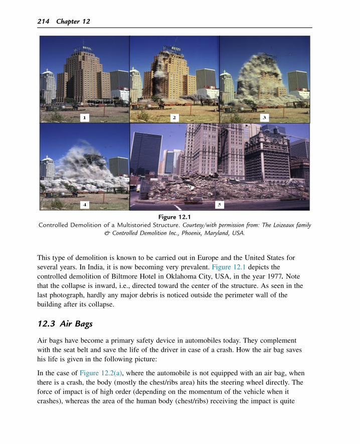
This type of demolition is known to be carried out in Europe and the United States for
several years. In India, it is now becoming very prevalent. Figure 12.1 depicts the
controlled demolition of Biltmore Hotel in Oklahoma City, USA, in the year 1977. Note
that the collapse is inward, i.e., directed toward the center of the structure. As seen in the
last photograph, hardly any major debris is noticed outside the perimeter wall of the
building after its collapse.
12.3 Air Bags
Air bags have become a primary safety device in automobiles today. They complement
with the seat belt and save the life of the driver in case of a crash. How the air bag saves
his life is given in the following picture:
In the case of Figure 12.2(a), where the automobile is not equipped with an air bag, when
there is a crash, the body (mostly the chest/ribs area) hits the steering wheel directly. The
force of impact is of high order (depending on the momentum of the vehicle when it
crashes), whereas the area of the human body (chest/ribs) receiving the impact is quite
Figure 12.1Controlled Demolition of a Multistoried Structure. Courtesy/with permission from: The Loizeaux family
& Controlled Demolition Inc., Phoenix, Maryland, USA.
214 Chapter 12
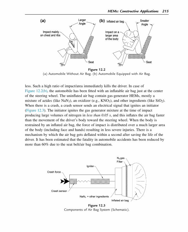
less. Such a high ratio of impact/area immediately kills the driver. In case of
Figure 12.2(b), the automobile has been fitted with an inflatable air bag just at the center
of the steering wheel. The uninflated air bag contain gas-generator HEMs, mostly a
mixture of azides (like NaN3), an oxidizer (e.g., KNO3), and other ingredients (like SiO2).
When there is a crash, a crash sensor sends an electrical signal that ignites an initiator
(Figure 12.3). The initiator ignites the gas generator mixture at the time of impact
producing large volumes of nitrogen in less than 0.05 s, and this inflates the air bag faster
than the movement of the driver’s body toward the steering wheel. When the body is
restrained by an inflated air bag, the force of impact is distributed over a much larger area
of the body (including face and hands) resulting in less severe injuries. There is a
mechanism by which the air bag gets deflated within a second after saving the life of the
driver. It has been estimated that the fatality in automobile accidents has been reduced by
more than 60% due to the seat belt/air bag combination.
Figure 12.2(a) Automobile Without Air Bag. (b) Automobile Equipped with Air Bag.
Figure 12.3Components of Air Bag System (Schematic).
HEMs: Constructive Applications 215
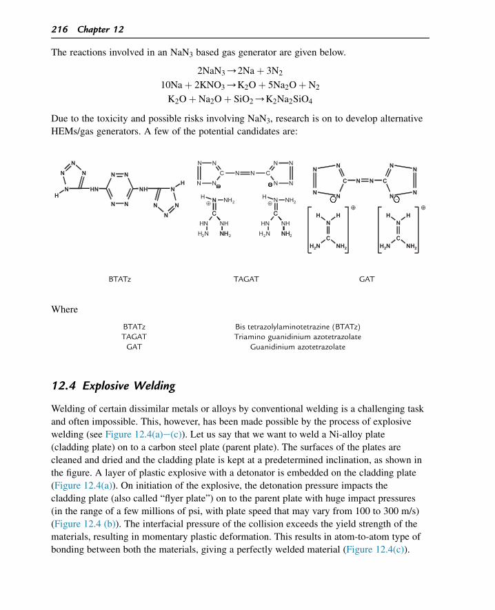
The reactions involved in an NaN3 based gas generator are given below.
2NaN3/2Naþ 3N2
10Naþ 2KNO3/K2Oþ 5Na2Oþ N2
K2Oþ Na2Oþ SiO2/K2Na2SiO4
Due to the toxicity and possible risks involving NaN3, research is on to develop alternative
HEMs/gas generators. A few of the potential candidates are:
Where
BTATz Bis tetrazolylaminotetrazine (BTATz)TAGAT Triamino guanidinium azotetrazolateGAT Guanidinium azotetrazolate
12.4 Explosive Welding
Welding of certain dissimilar metals or alloys by conventional welding is a challenging task
and often impossible. This, however, has been made possible by the process of explosive
welding (see Figure 12.4(a)e(c)). Let us say that we want to weld a Ni-alloy plate
(cladding plate) on to a carbon steel plate (parent plate). The surfaces of the plates are
cleaned and dried and the cladding plate is kept at a predetermined inclination, as shown in
the figure. A layer of plastic explosive with a detonator is embedded on the cladding plate
(Figure 12.4(a)). On initiation of the explosive, the detonation pressure impacts the
cladding plate (also called “flyer plate”) on to the parent plate with huge impact pressures
(in the range of a few millions of psi, with plate speed that may vary from 100 to 300 m/s)
(Figure 12.4 (b)). The interfacial pressure of the collision exceeds the yield strength of the
materials, resulting in momentary plastic deformation. This results in atom-to-atom type of
bonding between both the materials, giving a perfectly welded material (Figure 12.4(c)).
N N
NN
NHHN N
NN
N
HN
NN
N
H
NN
C
N N
N N
C
NN
N N
C
NH
NH
C
NH2
C
NH
NH
C
NH2
HN
H2N H2N
HN
NH2 N NH2H H
⊕ ⊕N
N
C
HH
NH2H2N
N
C
N
N
N
N
N
C
N
N
N
N
N
C
HH
NH2H2N
−−
⊕ ⊕
BTATz TAGAT GAT
216 Chapter 12
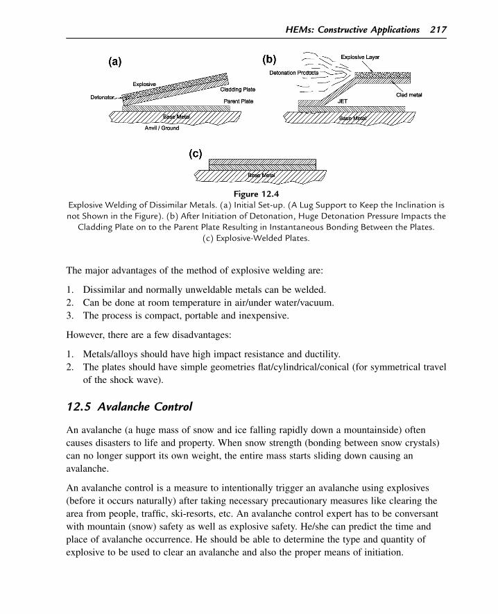
The major advantages of the method of explosive welding are:
1. Dissimilar and normally unweldable metals can be welded.
2. Can be done at room temperature in air/under water/vacuum.
3. The process is compact, portable and inexpensive.
However, there are a few disadvantages:
1. Metals/alloys should have high impact resistance and ductility.
2. The plates should have simple geometries flat/cylindrical/conical (for symmetrical travel
of the shock wave).
12.5 Avalanche Control
An avalanche (a huge mass of snow and ice falling rapidly down a mountainside) often
causes disasters to life and property. When snow strength (bonding between snow crystals)
can no longer support its own weight, the entire mass starts sliding down causing an
avalanche.
An avalanche control is a measure to intentionally trigger an avalanche using explosives
(before it occurs naturally) after taking necessary precautionary measures like clearing the
area from people, traffic, ski-resorts, etc. An avalanche control expert has to be conversant
with mountain (snow) safety as well as explosive safety. He/she can predict the time and
place of avalanche occurrence. He should be able to determine the type and quantity of
explosive to be used to clear an avalanche and also the proper means of initiation.
Figure 12.4Explosive Welding of Dissimilar Metals. (a) Initial Set-up. (A Lug Support to Keep the Inclination isnot Shown in the Figure). (b) After Initiation of Detonation, Huge Detonation Pressure Impacts the
Cladding Plate on to the Parent Plate Resulting in Instantaneous Bonding Between the Plates.(c) Explosive-Welded Plates.
HEMs: Constructive Applications 217
Avalanche control prevents disasters such as people, tenements, and vehicles being buried
under snow (please refer Chapter 4, Figure. 4.14).
12.6 Life Saving Applications
HEMs find a life-saving application for emergency exit of fighter pilots. In case the pilot
wants to abandon the aircraft during an emergency, an explosive device severs and
dislodges the canopy, following which a propulsion device under his seat ejects the pilot
and parachute from the aircraft. The design and development of the explosive system for
canopy severance and the propellants/propulsion system for seat ejection is a very critical
job, as it involves the life of the pilot. Many lives have been and are being saved by a
combination of seat ejection and canopy severance devices where the HEMs play a very
critical role.
In the field of medicine, nitroglycerineda well-known explosivedhas saved the lives of
many patients suffering from coronary heart disease. NG-based tablets are known to
prevent or stop the chest pain (angina) among such patients. NG dilates the blood vessels,
leading to more blood flow and oxygen supply to the heart. NG-based tablets are strictly
prescribed medicines and should be taken only as per strict medical advice.
There has been an interesting and rather weird application of explosives in tenderization of
meat! It was discovered by Morse Solomon, a meat scientist, and John Long, that huge
quantities of meat kept under water get tenderized by subjecting them to underwater
explosion. It has been estimated that this method of tenderization of meat is far cheaper
than methods involving electrical power. Probably some of the potential applications by
HEMs are yet to be discovered.
Suggested Reading
[1] E.G. Mahadevan, Ammonium Nitrate Explosives for Civil Applications Slurries, Emulsions andAmmonium Nitrate Fuel Oils, first ed., Wiley-VCH, 2013.
[2] The Explosive Engineer: Forerunner of Progress in Mining, Quarrying, Construction, vol. 20, ContributorHercules Powder Company, Publisher Hercules Powder Company, 1942.
[3] E.G. Baranov, A.T. Vedin, I.F. Bondarenko, Mining and Industrial Applications of Low DensityExplosives, Taylor & Francis, 1996.
[4] D.E. Davenport, Explosive Welding, American Society of Tool and Manufacturing Engineers, 1961.[5] T.Z. Blazynski, Explosive Welding, Forming and Compaction, first ed., Springer, 1983.[6] E.O. Paton, Explosive Welding of Metal Layered Composite Materials Welding and Allied Processes,
International welding Association, 2003.[7] R.A. Patterson, Fundamentals of Explosion Welding, ASM Handbook, vol. 6, Welding, Brazing, and
Soldering (ASM International), 1993.[8] B. Crossland, Explosive Welding of Metals and its Application, Clarendon Press, 1982.
218 Chapter 12

Questions
1. What are the important factors to be considered in the controlled demolition of high-
rise structures?
2. How does an automobile air bag work?
3. What is an avalanche and how can it be controlled using explosives?
4. What do you understand by canopy severance system? How does an explosive and
propellant system save the life of an aircraft pilot during an emergency?
5. What is meant by explosive welding? What are its advantages over conventional welding?
6. How does nitroglycerine help in relieving angina?
HEMs: Constructive Applications 219

This page intentionally left blank
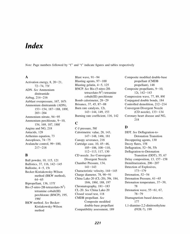
Index
Note: Page numbers followed by “f” and “t” indicate figures and tables respectively
A
Activation energy, 8, 20e21,72e74, 73f
ADN. See Ammoniumdinitramide
Airbag, 214e216Airblast overpressure, 167, 167tAmmonium dinitramide (ADN),
153e154, 187e188, 189f,203e204
Ammonium nitrate, 94e95Ammonium perchlorate, 9e10,
154, 169, 187, 188fAngina and NG, 218Antacids, 128Arrhenius equation, 73Auxoploses, 74e75Avalanche control, 99e100,
217e218
B
Ball powder, 10, 115, 121Ballistics, 37, 116, 142e145Ballistite, 4e5, 15tBecker-Kistiakowsky-Wilson
method (BKW method),64e65
Bipropellant, 136, 137fBis-(5-nitro-2H-tetrazolato-N2)
tetramine cobalt(III)perchlorate (BNCP), 195,196f
BKW method. See Becker-Kistiakowsky-Wilsonmethod
Blast wave, 91e94Blasting agents, 97e100Blasting gelatin, 4e5, 125BNCP. See Bis-(5-nitro-2H-
tetrazolato-N2) tetraminecobalt(III) perchlorate
Bomb calorimeter, 28e29Brisance, 37, 45, 87e88Burn rate catalysts, 12t,
143e144, 149, 153Burning rate coefficient, 116, 142
C
C-J pressure, 58fCalorimetric value, 28, 143,
147e148, 148t, 181Canopy severance, 218Cartridge case, 10, 45e46,
105e106, 108e110,112e113, 117, 130
CD nozzle. See Convergent-Divergent Nozzle
Chamber Pressure, 134,141e143
Characteristic velocity, 144e145Charge diameter, 78, 90e91China Lake-20 (CL-20), 59t, 184,
184t, 186f, 188, 197Chromatography, 181e183CL-20. See China Lake-20Closed vessel test, 118CMDB propellant. See
Composite modifieddouble-base propellant
Compatibility assessment, 189
Composite modified double-basepropellant (CMDBpropellant), 148
Composite propellants, 9e10,12t, 142e143
Compression wave, 77, 89, 89fConjugated double bonds, 184Controlled demolition, 212e214Convergent-Divergent Nozzle
(CD nozzle), 133e134Coronary heart disease and NG,
218
D
DDT. See Deflagration-to-Detonation Transition
Decoppering agents, 130Decoy flares, 158Deflagration, 52e56, 55tDeflagration-to-Detonation
Transition (DDT), 55, 67Delay composition, 13, 157e158Demilitarization, 206e207Detection of Explosives,
173e179Detonation, 52e54Detonation Pressure, 61e65Detonation temperature, 37e39,
78Detonation wave, 55e61, 67,
78e79Diamagnetism based detector,
1771,1-diamino-2,2-dinitroethylene
(FOX-7), 199
221
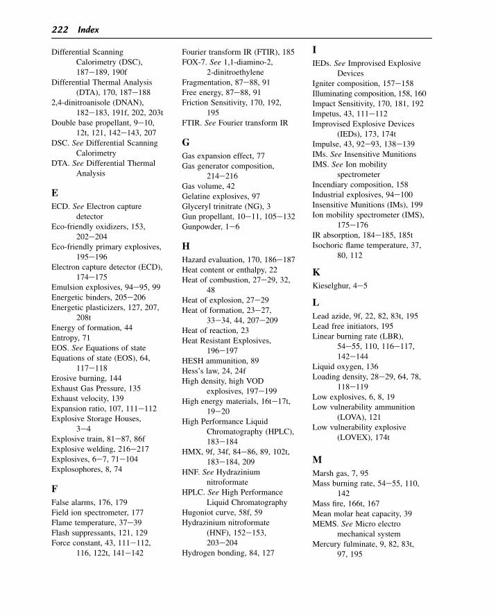
Differential ScanningCalorimetry (DSC),187e189, 190f
Differential Thermal Analysis(DTA), 170, 187e188
2,4-dinitroanisole (DNAN),182e183, 191f, 202, 203t
Double base propellant, 9e10,12t, 121, 142e143, 207
DSC. See Differential ScanningCalorimetry
DTA. See Differential ThermalAnalysis
E
ECD. See Electron capturedetector
Eco-friendly oxidizers, 153,202e204
Eco-friendly primary explosives,195e196
Electron capture detector (ECD),174e175
Emulsion explosives, 94e95, 99Energetic binders, 205e206Energetic plasticizers, 127, 207,
208tEnergy of formation, 44Entropy, 71EOS. See Equations of stateEquations of state (EOS), 64,
117e118Erosive burning, 144Exhaust Gas Pressure, 135Exhaust velocity, 139Expansion ratio, 107, 111e112Explosive Storage Houses,
3e4Explosive train, 81e87, 86fExplosive welding, 216e217Explosives, 6e7, 71e104Explosophores, 8, 74
F
False alarms, 176, 179Field ion spectrometer, 177Flame temperature, 37e39Flash suppressants, 121, 129Force constant, 43, 111e112,
116, 122t, 141e142
Fourier transform IR (FTIR), 185FOX-7. See 1,1-diamino-2,
2-dinitroethyleneFragmentation, 87e88, 91Free energy, 87e88, 91Friction Sensitivity, 170, 192,
195FTIR. See Fourier transform IR
G
Gas expansion effect, 77Gas generator composition,
214e216Gas volume, 42Gelatine explosives, 97Glyceryl trinitrate (NG), 3Gun propellant, 10e11, 105e132Gunpowder, 1e6
H
Hazard evaluation, 170, 186e187Heat content or enthalpy, 22Heat of combustion, 27e29, 32,
48Heat of explosion, 27e29Heat of formation, 23e27,
33e34, 44, 207e209Heat of reaction, 23Heat Resistant Explosives,
196e197HESH ammunition, 89Hess’s law, 24, 24fHigh density, high VOD
explosives, 197e199High energy materials, 16te17t,
19e20High Performance Liquid
Chromatography (HPLC),183e184
HMX, 9f, 34f, 84e86, 89, 102t,183e184, 209
HNF. See Hydraziniumnitroformate
HPLC. See High PerformanceLiquid Chromatography
Hugoniot curve, 58f, 59Hydrazinium nitroformate
(HNF), 152e153,203e204
Hydrogen bonding, 84, 127
I
IEDs. See Improvised ExplosiveDevices
Igniter composition, 157e158Illuminating composition, 158, 160Impact Sensitivity, 170, 181, 192Impetus, 43, 111e112Improvised Explosive Devices
(IEDs), 173, 174tImpulse, 43, 92e93, 138e139IMs. See Insensitive MunitionsIMS. See Ion mobility
spectrometerIncendiary composition, 158Industrial explosives, 94e100Insensitive Munitions (IMs), 199Ion mobility spectrometer (IMS),
175e176IR absorption, 184e185, 185tIsochoric flame temperature, 37,
80, 112
K
Kieselghur, 4e5
L
Lead azide, 9f, 22, 82, 83t, 195Lead free initiators, 195Linear burning rate (LBR),
54e55, 110, 116e117,142e144
Liquid oxygen, 136Loading density, 28e29, 64, 78,
118e119Low explosives, 6, 8, 19Low vulnerability ammunition
(LOVA), 121Low vulnerability explosive
(LOVEX), 174t
M
Marsh gas, 7, 95Mass burning rate, 54e55, 110,
142Mass fire, 166t, 167Mean molar heat capacity, 39MEMS. See Micro electro
mechanical systemMercury fulminate, 9, 82, 83t,
97, 195
222 Index
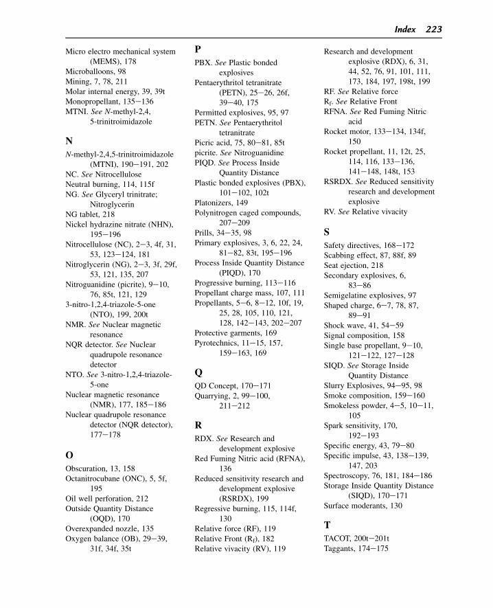
Micro electro mechanical system(MEMS), 178
Microballoons, 98Mining, 7, 78, 211Molar internal energy, 39, 39tMonopropellant, 135e136MTNI. See N-methyl-2,4,
5-trinitroimidazole
N
N-methyl-2,4,5-trinitroimidazole(MTNI), 190e191, 202
NC. See NitrocelluloseNeutral burning, 114, 115fNG. See Glyceryl trinitrate;
NitroglycerinNG tablet, 218Nickel hydrazine nitrate (NHN),
195e196Nitrocellulose (NC), 2e3, 4f, 31,
53, 123e124, 181Nitroglycerin (NG), 2e3, 3f, 29f,
53, 121, 135, 207Nitroguanidine (picrite), 9e10,
76, 85t, 121, 1293-nitro-1,2,4-triazole-5-one
(NTO), 199, 200tNMR. See Nuclear magnetic
resonanceNQR detector. See Nuclear
quadrupole resonancedetector
NTO. See 3-nitro-1,2,4-triazole-5-one
Nuclear magnetic resonance(NMR), 177, 185e186
Nuclear quadrupole resonancedetector (NQR detector),177e178
O
Obscuration, 13, 158Octanitrocubane (ONC), 5, 5f,
195Oil well perforation, 212Outside Quantity Distance
(OQD), 170Overexpanded nozzle, 135Oxygen balance (OB), 29e39,
31f, 34f, 35t
P
PBX. See Plastic bondedexplosives
Pentaerythritol tetranitrate(PETN), 25e26, 26f,39e40, 175
Permitted explosives, 95, 97PETN. See Pentaerythritol
tetranitratePicric acid, 75, 80e81, 85tpicrite. See NitroguanidinePIQD. See Process Inside
Quantity DistancePlastic bonded explosives (PBX),
101e102, 102tPlatonizers, 149Polynitrogen caged compounds,
207e209Prills, 34e35, 98Primary explosives, 3, 6, 22, 24,
81e82, 83t, 195e196Process Inside Quantity Distance
(PIQD), 170Progressive burning, 113e116Propellant charge mass, 107, 111Propellants, 5e6, 8e12, 10f, 19,
25, 28, 105, 110, 121,128, 142e143, 202e207
Protective garments, 169Pyrotechnics, 11e15, 157,
159e163, 169
Q
QD Concept, 170e171Quarrying, 2, 99e100,
211e212
R
RDX. See Research anddevelopment explosive
Red Fuming Nitric acid (RFNA),136
Reduced sensitivity research anddevelopment explosive(RSRDX), 199
Regressive burning, 115, 114f,130
Relative force (RF), 119Relative Front (Rf), 182Relative vivacity (RV), 119
Research and developmentexplosive (RDX), 6, 31,44, 52, 76, 91, 101, 111,173, 184, 197, 198t, 199
RF. See Relative forceRf. See Relative FrontRFNA. See Red Fuming Nitric
acidRocket motor, 133e134, 134f,
150Rocket propellant, 11, 12t, 25,
114, 116, 133e136,141e148, 148t, 153
RSRDX. See Reduced sensitivityresearch and developmentexplosive
RV. See Relative vivacity
S
Safety directives, 168e172Scabbing effect, 87, 88f, 89Seat ejection, 218Secondary explosives, 6,
83e86Semigelatine explosives, 97Shaped charge, 6e7, 78, 87,
89e91Shock wave, 41, 54e59Signal composition, 158Single base propellant, 9e10,
121e122, 127e128SIQD. See Storage Inside
Quantity DistanceSlurry Explosives, 94e95, 98Smoke composition, 159e160Smokeless powder, 4e5, 10e11,
105Spark sensitivity, 170,
192e193Specific energy, 43, 79e80Specific impulse, 43, 138e139,
147, 203Spectroscopy, 76, 181, 184e186Storage Inside Quantity Distance
(SIQD), 170e171Surface moderants, 130
T
TACOT, 200te201tTaggants, 174e175
Index 223
TATB. See Triaminotrinitrobenzene
Tenderization of meat, 218Tension wave, 89Tetryl, 84e86, 191e192TGA. See Thermogravimetric
analysisThermal analysis, 181, 187Thermally stable explosive,
196e197, 200te201t, 202Thermite composition, 162Thermogravimetric analysis
(TGA), 187, 189e191Thermoredox detector, 176Throat area, 146Thrust coefficient, 144
TNAZ. See 1,3,3-trinitroazetidineTNT. See TrinitrotolueneTotal impulse, 138Total thrust, 134, 145Toxic Hazards, 169e170Tracer composition, 158Triamino trinitrobenzene (TATB),
84, 200te201t1,3,3-trinitroazetidine (TNAZ),
202Trinitrotoluene (TNT), 3, 9f,
30e31, 54, 63, 100, 101t,199e202
Triple base propellant, 9e10,121, 129
U
Hazard Classification, 166e167Underexpanded nozzle, 135Unit of Isp, 138
V
Velocity of detonation (VOD),6e7, 36, 54, 59, 62,77e79, 85t, 181
Vielle Law, 53, 116e118, 142Vivacity, 116, 119
W
Waste Disposal, 163, 167, 172
224 Index