Embed Size (px)
Citation preview
Demountable Concepts, Inc. • 200 Acorn Road, Glassboro, New Jersey 08028 • USA 1-800-254-3643 | www.demount.com
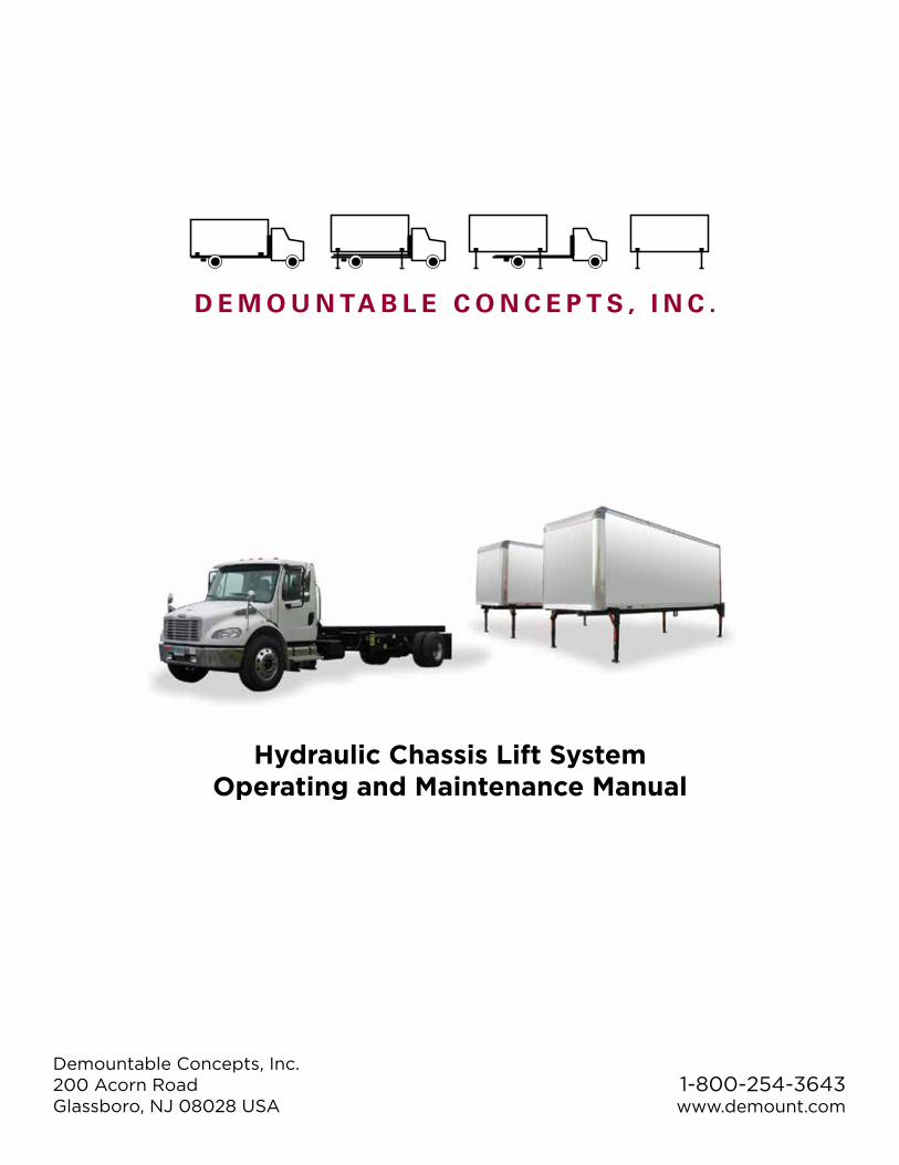
Hydraulic Chassis Lift System Operating and Maintenance Manual
Page 1© 2013 Demountable Concepts, Inc.
Hydraulic Chassis Lift System Operating and Maintenance Manual
Demountable Concepts, Inc.200 Acorn RoadGlassboro, NJ 08028 USA
1-800-254-3643www.demount.com
Demountable Concepts, Inc. • 200 Acorn Road, Glassboro, New Jersey 08028 • USA 1-800-254-3643 | www.demount.com
Hydraulic Chassis Lift System Operating and Maintenance Manual
Page 2© 2013 Demountable Concepts, Inc.
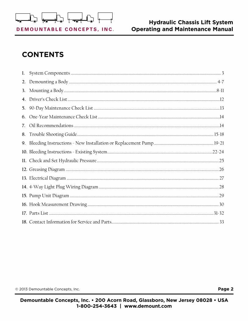
CONTENTS
1. System Components ................................................................................................................................................ 3
2. Demounting a Body .............................................................................................................................................. 4-7
3. Mounting a Body ...................................................................................................................................................8-11
4. Driver’s Check List ..................................................................................................................................................12
5. 90-Day Maintenance Check List .........................................................................................................................13
6. One-Year Maintenance Check List .....................................................................................................................14
7. Oil Recommendations ............................................................................................................................................14
8. Trouble Shooting Guide ................................................................................................................................... 15-18
9. Bleeding Instructions - New Installation or Replacement Pump ......................................................... 19-21
10. Bleeding Instructions - Existing System .....................................................................................................22-24
11. Check and Set Hydraulic Pressure .....................................................................................................................25
12. Greasing Diagram ...................................................................................................................................................26
13. Electrical Diagram .................................................................................................................................................. 27
14. 4-Way Light Plug Wiring Diagram ...................................................................................................................28
15. Pump Unit Diagram ...............................................................................................................................................29
16. Hook Measurement Drawing ..............................................................................................................................30
17. Parts List ..............................................................................................................................................................31-32
18. Contact Information for Service and Parts....................................................................................................... 33
Demountable Concepts, Inc. • 200 Acorn Road, Glassboro, New Jersey 08028 • USA 1-800-254-3643 | www.demount.com
Hydraulic Chassis Lift System Operating and Maintenance Manual
Page 3© 2013 Demountable Concepts, Inc.
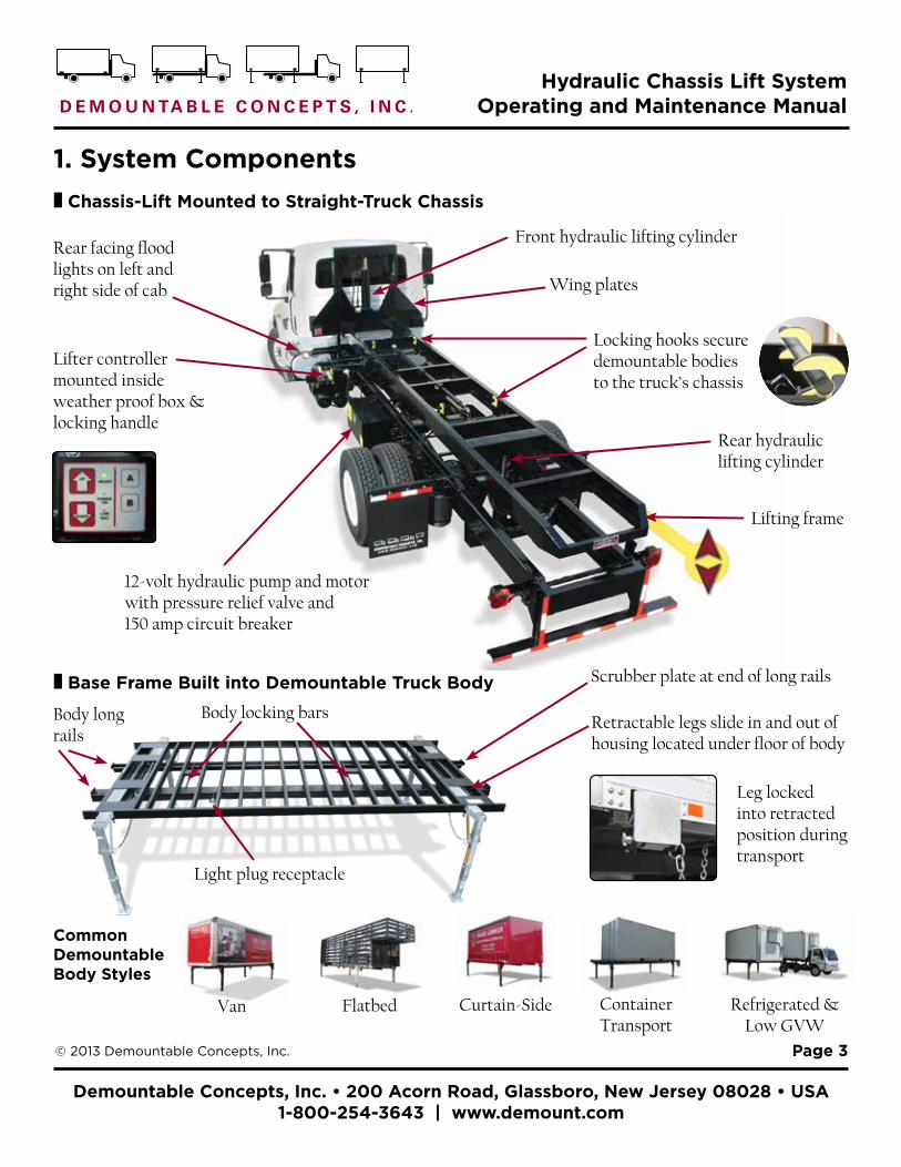
1. System Components
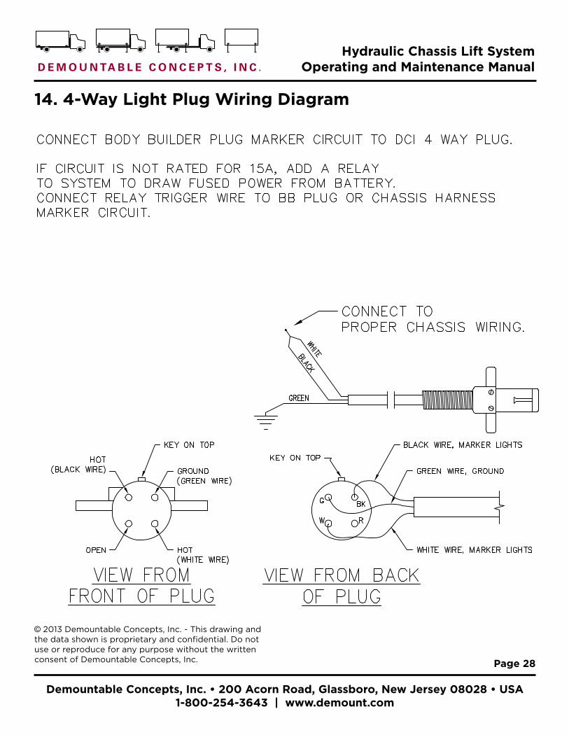
Front hydraulic lifting cylinderRear facing flood lights on left and right side of cab
Lifter controller mounted insideweather proof box & locking handle
Rear hydraulic lifting cylinder
Locking hooks secure demountable bodies to the truck’s chassis
12-volt hydraulic pump and motor with pressure relief valve and 150 amp circuit breaker
¦ Chassis-Lift Mounted to Straight-Truck Chassis
¦ Base Frame Built into Demountable Truck Body
Retractable legs slide in and out ofhousing located under floor of body
FlatbedVan Curtain-Side Container Transport
Refrigerated & Low GVW
Leg locked into retracted position during transport
Lifting frame
Body long rails
Body locking bars
Wing plates
CommonDemountable Body Styles
Light plug receptacle
Scrubber plate at end of long rails

Demountable Concepts, Inc. • 200 Acorn Road, Glassboro, New Jersey 08028 • USA 1-800-254-3643 | www.demount.com
Hydraulic Chassis Lift System Operating and Maintenance Manual
Page 4© 2013 Demountable Concepts, Inc.
2. Demounting a Truck Body¦ Preparing to Demount a Body
1. Put the truck in neutral and set the parking brake.
2. IMPORTANT: For lift gate-equipped vehicles, unlock and lower the lift gate to clear body long rails. See Figure 1.
NOTE: The cab-mounted safety buzzer/light will activate. This indicator will continue until the body is properly locked onto the truck chassis.
¦ Unlocking the Demountable Body
1. Remove lock key. 2. Push yellow safety pin handle in to unlock pin.
3. Push the large black locking handle down.
¦ Disconnecting the Light Plug
1. Disconnect the light plug from the body.
2. Insert the plug into the light plug holder.
WARNING: Never Drive with the Body Elevated or Unlocked
!
Figure 1.
Lift gateBody long rails
Demountable Concepts, Inc. • 200 Acorn Road, Glassboro, New Jersey 08028 • USA 1-800-254-3643 | www.demount.com
Hydraulic Chassis Lift System Operating and Maintenance Manual
Page 5© 2013 Demountable Concepts, Inc.
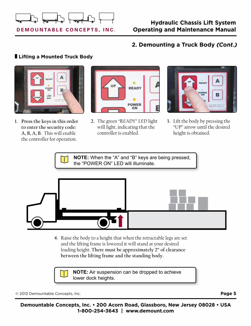
¦ Lifting a Mounted Truck Body
4. Raise the body to a height that when the retractable legs are set and the lifting frame is lowered it will stand at your desired loading height. There must be approximately 2" of clearance between the lifting frame and the standing body.
2. Demounting a Truck Body (Cont.)
1. Press the keys in this order to enter the security code: A, B, A, B. This will enable the controller for operation.
2. The green “READY” LED light will light, indicating that the controller is enabled.
3. Lift the body by pressing the “UP” arrow until the desired height is obtained.
NOTE: When the “A” and “B” keys are being pressed, the “POWER ON” LED will illuminate.
NOTE: Air suspension can be dropped to achieve lower dock heights.

Demountable Concepts, Inc. • 200 Acorn Road, Glassboro, New Jersey 08028 • USA 1-800-254-3643 | www.demount.com
Hydraulic Chassis Lift System Operating and Maintenance Manual
Page 6© 2013 Demountable Concepts, Inc.
2. Demounting a Truck Body (Cont.)
¦ Setting the Retractable Legs
1. Unlock and remove the chained pin from the foot of leg under the body side rail.
2. Grip the leg with fingers wrapped around the underside of the foot pad.
3. Pull the leg all the way out and lower it to the vertical position
NOTE: When setting the legs ALWAYS wear gloves for hand protection.
4. Adjust the lower section of the leg to be as close to the ground as possible and insert pin to secure it at that height.
A
B
5. Put chained pin through upper stabilizing brace and leg.
6. Push leg assembly into the body leg housing until brace touches the truck body.
7. Check that all pins are secured into the proper position with tab perpendicular to pin.
WARNING: NEVER put fingers into holes in legs.!
Tab in proper position for securing pins
Demountable Concepts, Inc. • 200 Acorn Road, Glassboro, New Jersey 08028 • USA 1-800-254-3643 | www.demount.com
Hydraulic Chassis Lift System Operating and Maintenance Manual
Page 7© 2013 Demountable Concepts, Inc.
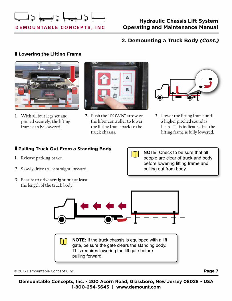
¦ Pulling Truck Out From a Standing Body
1. Release parking brake.
2. Slowly drive truck straight forward.
3. Be sure to drive straight out at least the length of the truck body.
2. Demounting a Truck Body (Cont.)
¦ Lowering the Lifting Frame
1. With all four legs set and pinned securely, the lifting frame can be lowered.
2. Push the “DOWN” arrow on the lifter controller to lower the lifting frame back to the truck chassis.
3. Lower the lifting frame until a higher pitched sound is heard. This indicates that the lifting frame is fully lowered.
NOTE: If the truck chassis is equipped with a lift gate, be sure the gate clears the standing body. This requires lowering the lift gate before pulling forward.
NOTE: Check to be sure that all people are clear of truck and body before lowering lifting frame and pulling out from body.
Demountable Concepts, Inc. • 200 Acorn Road, Glassboro, New Jersey 08028 • USA 1-800-254-3643 | www.demount.com
Hydraulic Chassis Lift System Operating and Maintenance Manual
Page 8© 2013 Demountable Concepts, Inc.
3. Mounting a Truck Body
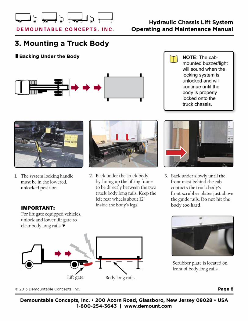
¦ Backing Under the Body
1. The system locking handle must be in the lowered, unlocked position.
2. Back under the truck body by lining up the lifting frame to be directly between the two truck body long rails. Keep the left rear wheels about 12" inside the body’s legs.
3. Back under slowly until the front mast behind the cab contacts the truck body’s front scrubber plates just above the guide rails. Do not hit the body too hard.IMPORTANT:
For lift gate equipped vehicles, unlock and lower lift gate to clear body long rails
NOTE: The cab-mounted buzzer/light will sound when the locking system is unlocked and will continue until the body is properly locked onto the truck chassis.
Lift gate Body long rails
Scrubber plate is located on front of body long rails
Demountable Concepts, Inc. • 200 Acorn Road, Glassboro, New Jersey 08028 • USA 1-800-254-3643 | www.demount.com
Hydraulic Chassis Lift System Operating and Maintenance Manual
Page 9© 2013 Demountable Concepts, Inc.
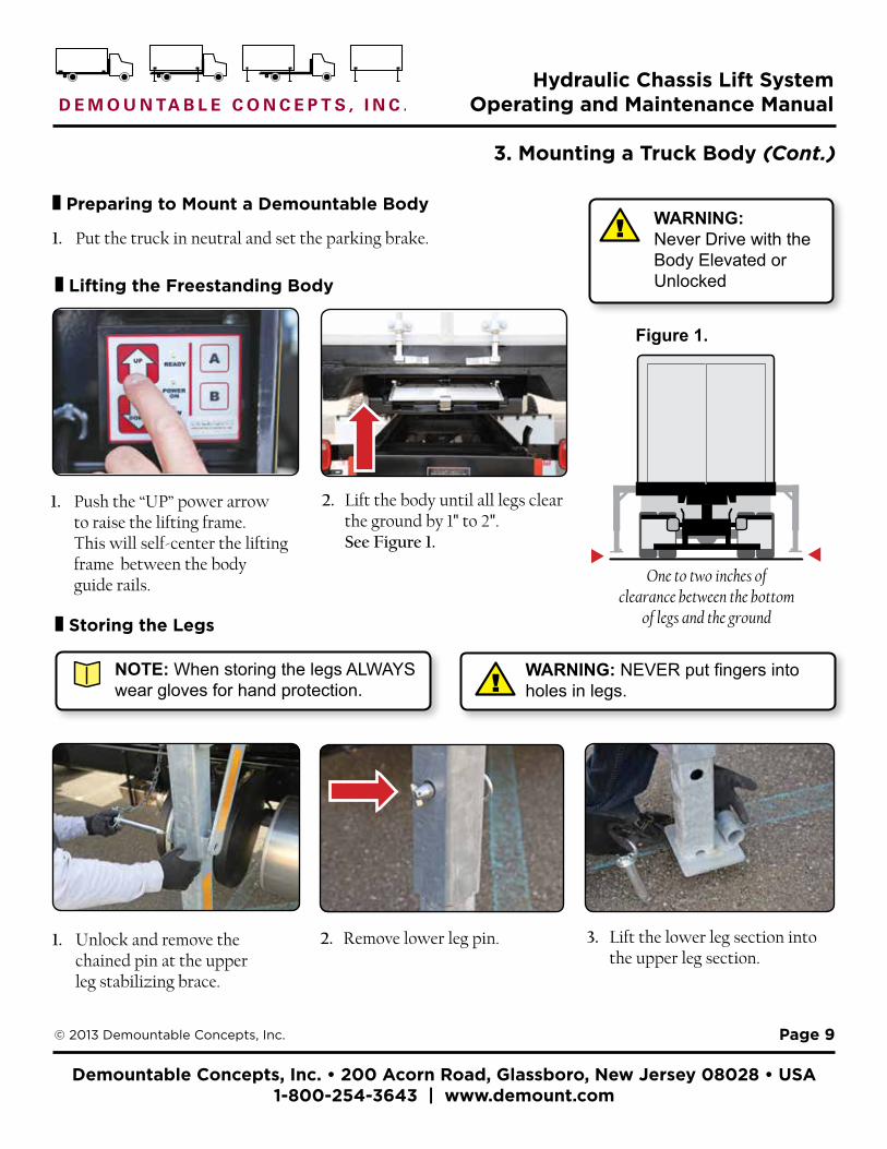
¦ Storing the Legs
1. Unlock and remove the chained pin at the upper leg stabilizing brace.
2. Remove lower leg pin. 3. Lift the lower leg section into the upper leg section.
3. Mounting a Truck Body (Cont.)
¦ Lifting the Freestanding Body
1. Push the “UP” power arrow to raise the lifting frame. This will self-center the lifting frame between the body guide rails.
2. Lift the body until all legs clear the ground by 1" to 2". See Figure 1.
¦ Preparing to Mount a Demountable Body
1. Put the truck in neutral and set the parking brake.WARNING: Never Drive with the Body Elevated or Unlocked
!
NOTE: When storing the legs ALWAYS wear gloves for hand protection.
WARNING: NEVER put fingers into holes in legs.!
One to two inches ofclearance between the bottom
of legs and the ground
Figure 1.
Demountable Concepts, Inc. • 200 Acorn Road, Glassboro, New Jersey 08028 • USA 1-800-254-3643 | www.demount.com
Hydraulic Chassis Lift System Operating and Maintenance Manual
Page 10© 2013 Demountable Concepts, Inc.
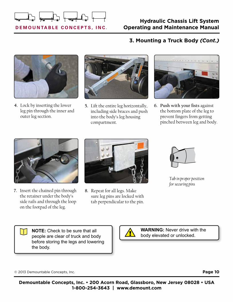
3. Mounting a Truck Body (Cont.)
5. Lift the entire leg horizontally, including side braces and push into the body’s leg housing compartment.
7. Insert the chained pin through the retainer under the body’s side rails and through the loop on the footpad of the leg.
8. Repeat for all legs. Make sure leg pins are locked with tab perpendicular to the pin.
WARNING: Never drive with the body elevated or unlocked.!
4. Lock by inserting the lower leg pin through the inner and outer leg section.
6. Push with your fists against the bottom plate of the leg to prevent fingers from getting pinched between leg and body.
Tab in proper position for securing pins
NOTE: Check to be sure that all people are clear of truck and body before storing the legs and lowering the body.
Demountable Concepts, Inc. • 200 Acorn Road, Glassboro, New Jersey 08028 • USA 1-800-254-3643 | www.demount.com
Hydraulic Chassis Lift System Operating and Maintenance Manual
Page 11© 2013 Demountable Concepts, Inc.
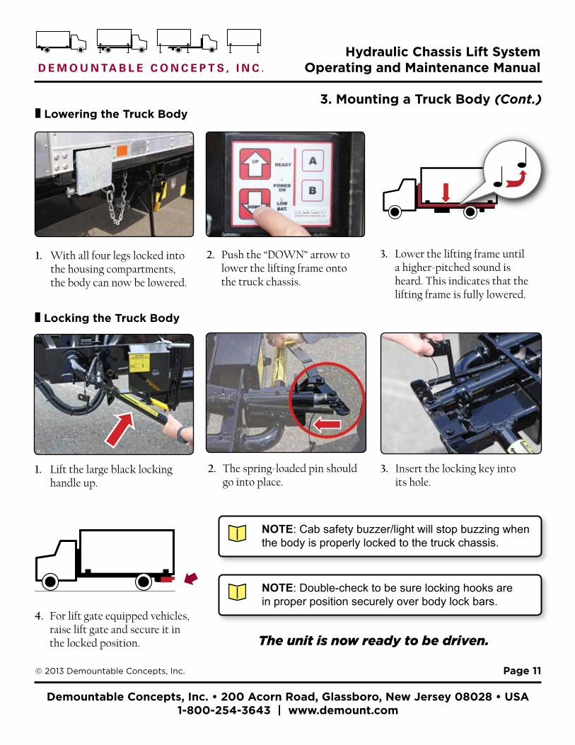
¦ Locking the Truck Body
1. Lift the large black locking handle up.
2. The spring-loaded pin should go into place.
3. Insert the locking key into its hole.
4. For lift gate equipped vehicles, raise lift gate and secure it in the locked position.
NOTE: Cab safety buzzer/light will stop buzzing when the body is properly locked to the truck chassis.
3. Mounting a Truck Body (Cont.)
The unit is now ready to be driven.
¦ Lowering the Truck Body
1. With all four legs locked into the housing compartments, the body can now be lowered.
2. Push the “DOWN” arrow to lower the lifting frame onto the truck chassis.
3. Lower the lifting frame until a higher-pitched sound is heard. This indicates that the lifting frame is fully lowered.
NOTE: Double-check to be sure locking hooks are in proper position securely over body lock bars.
Demountable Concepts, Inc. • 200 Acorn Road, Glassboro, New Jersey 08028 • USA 1-800-254-3643 | www.demount.com
Hydraulic Chassis Lift System Operating and Maintenance Manual
Page 12© 2013 Demountable Concepts, Inc.
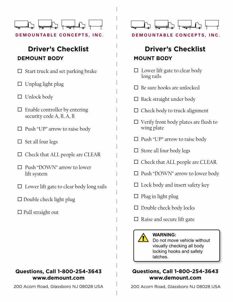
DEMOUNT BODY Start truck and set parking brake Unplug light plug Unlock body
Enable controller by entering security code A, B, A, B Push “UP” arrow to raise body Set all four legs Check that ALL people are CLEAR Push “DOWN” arrow to lower lift system
Lower lift gate to clear body long rails Double check light plug Pull straight out
MOUNT BODY Lower lift gate to clear body long rails
Be sure hooks are unlocked Back straight under body Check body to truck alignment Verify front body plates are flush to wing plate Push “UP” arrow to raise body Store all four body legs Check that ALL people are CLEAR Push “DOWN” arrow to lower body Lock body and insert safety key Plug in light plug Double check body locks
Raise and secure lift gate
Driver’s Checklist Driver’s Checklist
Questions, Call 1-800-254-3643www.demount.com
Questions, Call 1-800-254-3643 www.demount.com
200 Acorn Road, Glassboro NJ 08028 USA 200 Acorn Road, Glassboro NJ 08028 USA
WARNING: Do not move vehicle without visually checking all body locking hooks and safety latches.
!
Demountable Concepts, Inc. • 200 Acorn Road, Glassboro, New Jersey 08028 • USA 1-800-254-3643 | www.demount.com
Hydraulic Chassis Lift System Operating and Maintenance Manual
Page 13© 2013 Demountable Concepts, Inc.
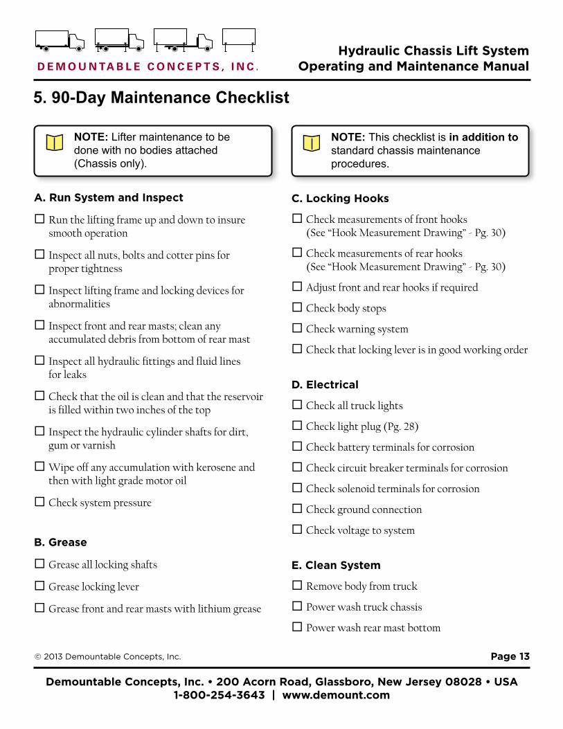
5. 90-Day Maintenance Checklist
A. Run System and Inspect
Run the lifting frame up and down to insure smooth operation
Inspect all nuts, bolts and cotter pins for proper tightness
Inspect lifting frame and locking devices for abnormalities
Inspect front and rear masts; clean any accumulated debris from bottom of rear mast
Inspect all hydraulic fittings and fluid lines for leaks
Check that the oil is clean and that the reservoir is filled within two inches of the top
Inspect the hydraulic cylinder shafts for dirt, gum or varnish
Wipe off any accumulation with kerosene and then with light grade motor oil
Check system pressure
B. Grease
Grease all locking shafts
Grease locking lever
Grease front and rear masts with lithium grease
C. Locking Hooks
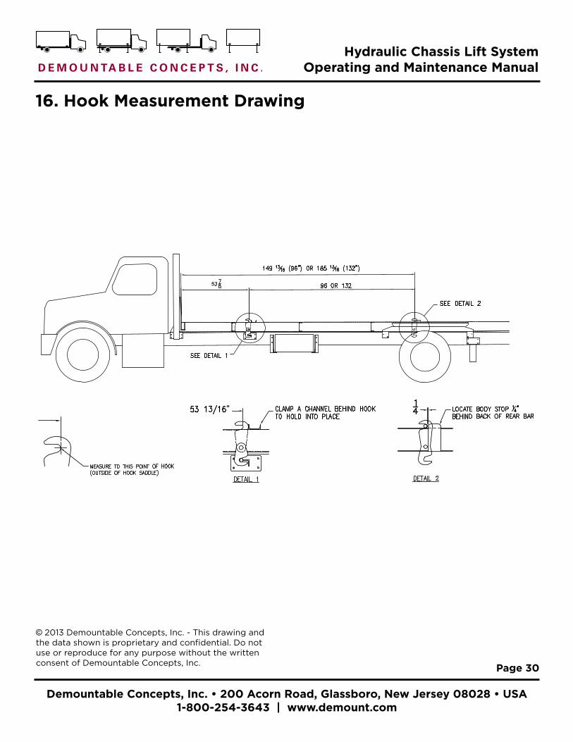
Check measurements of front hooks (See “Hook Measurement Drawing” - Pg. 30)
Check measurements of rear hooks (See “Hook Measurement Drawing” - Pg. 30)
Adjust front and rear hooks if required
Check body stops
Check warning system
Check that locking lever is in good working order
D. Electrical
Check all truck lights
Check light plug (Pg. 28)
Check battery terminals for corrosion
Check circuit breaker terminals for corrosion
Check solenoid terminals for corrosion
Check ground connection
Check voltage to system
E. Clean System
Remove body from truck
Power wash truck chassis
Power wash rear mast bottom
NOTE: Lifter maintenance to be done with no bodies attached (Chassis only).
NOTE: This checklist is in addition to standard chassis maintenance procedures.

Demountable Concepts, Inc. • 200 Acorn Road, Glassboro, New Jersey 08028 • USA 1-800-254-3643 | www.demount.com
Hydraulic Chassis Lift System Operating and Maintenance Manual
Page 14© 2013 Demountable Concepts, Inc.
6. One-Year Maintenance Checklist
Change oil Check hooks
7. Oil Recommendations
The hydraulic fluid in the system should be changed as a part of the periodic maintenance of the truck or any time it has become contaminated. 1. Use Automatic Transmission Fluid, Shell Tellus T-32, Mobil DTE-11 or equivalent hydraulic oil. 2. Keep the system clean in order to keep the oil clean. 3. Store oil in a clean and dry area to keep it free from water and contaminants. 4. Check that the oil is clean. 5. When changing or adding oil, be careful not to let contaminants into the system.
Demountable Concepts, Inc. • 200 Acorn Road, Glassboro, New Jersey 08028 • USA 1-800-254-3643 | www.demount.com
Hydraulic Chassis Lift System Operating and Maintenance Manual
Page 15© 2013 Demountable Concepts, Inc.
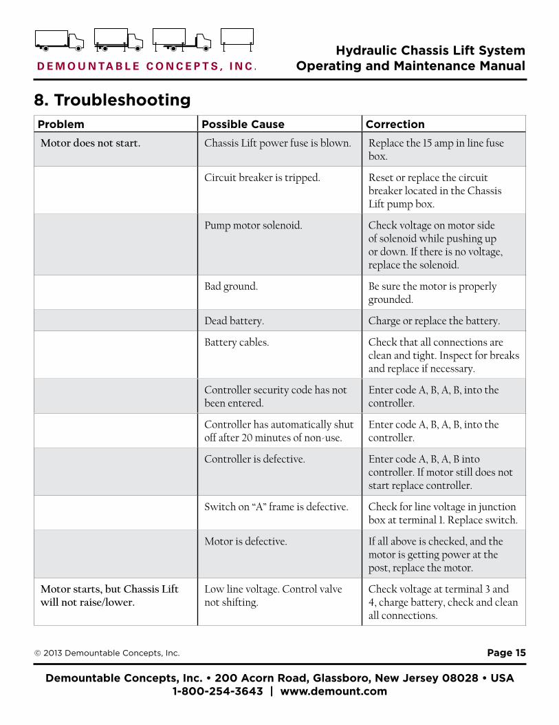
Problem Possible Cause Correction
Motor does not start. Chassis Lift power fuse is blown. Replace the 15 amp in line fuse box.
Circuit breaker is tripped. Reset or replace the circuit breaker located in the Chassis Lift pump box.
Pump motor solenoid. Check voltage on motor side of solenoid while pushing up or down. If there is no voltage, replace the solenoid.
Bad ground. Be sure the motor is properly grounded.
Dead battery. Charge or replace the battery.
Battery cables. Check that all connections are clean and tight. Inspect for breaks and replace if necessary.
Controller security code has not been entered.
Enter code A, B, A, B, into the controller.
Controller has automatically shut off after 20 minutes of non-use.
Enter code A, B, A, B, into the controller.
Controller is defective. Enter code A, B, A, B into controller. If motor still does not start replace controller.
Switch on “A” frame is defective. Check for line voltage in junction box at terminal 1. Replace switch.
Motor is defective. If all above is checked, and the motor is getting power at the post, replace the motor.
Motor starts, but Chassis Lift will not raise/lower.
Low line voltage. Control valve not shifting.
Check voltage at terminal 3 and 4, charge battery, check and clean all connections.
8. Troubleshooting

Demountable Concepts, Inc. • 200 Acorn Road, Glassboro, New Jersey 08028 • USA 1-800-254-3643 | www.demount.com
Hydraulic Chassis Lift System Operating and Maintenance Manual
Page 16© 2013 Demountable Concepts, Inc.
Problem Possible Cause Correction
Clogged pressure relief valve. Clear pressure relief valve and reset pressure per instructions.
Defective pressure relief valve. If above process doesn’t work, replace the valve.
Defective control valve. Replace valve.
After two lifts the Chassis Lift will only raise.
Controller in “low battery” state. Hold both A and B buttons down at the same time for 13 seconds to reset controller. Correct condition causing low voltage.
Chassis Lift FRONT goes down, but BACK will not go down all of the way.
Ice or debris on, or between truck chassis and lifter.
Raise Chassis Lift and clean off debris.
Dirt and/or rocks in rear mast. Clean or power wash rear mast and bottom section.
Not enough oil in closed section of hydraulic system.
Open rear bleeder plug and push down button (See “Bleeding Instructions” - Pg. 22). Be sure you have 1500 PSI.
Chassis Lift BACK goes down but FRONT will not go down all of the way.
Ice or debris on or between truck chassis and lifter.
Raise Chassis Lift and clean off debris.
Excess oil in closed section. Open front bleeder plug and push the down arrow on the controller (See “Bleeding Instructions” - Pg. 22). Be sure there is 1500 PSI.
Defective pressure relief valve in front of system.
Replace pressure relief valve at front cylinder.
Bad rear cylinder piston seals. Replace rear cylinder piston seals or cylinder.
8. Troubleshooting (Cont.)

Demountable Concepts, Inc. • 200 Acorn Road, Glassboro, New Jersey 08028 • USA 1-800-254-3643 | www.demount.com
Hydraulic Chassis Lift System Operating and Maintenance Manual
Page 17© 2013 Demountable Concepts, Inc.
Problem Possible Cause Correction
Chassis Lift BACK goes up but the FRONT does not.
Not enough oil in closed section of hydraulic system.
Open rear bleeder plug and push the down arrow on the controller. Be sure you have 1500 PSI.
Chassis Lift moves side to side. Too much space between front and/or rear masts - plastic slide blocks and channel.
Raise Chassis Lift half way and place shims behind plastic slide blocks until tight. Call factory - 1-800-254-3643.
Front or Rear mast is bent. Call factory - 1-800-254-3643.
Body will not lock on easily. Body is not forward enough. Back the truck up until the front wing plates contact the front plates on the front of the body.
Body is not forward enough. Check and remove any ice, snow, debris or obstruction that may be built up in front of body.
Ice or debris on or between truck chassis and lifter.
Raise Chassis Lift and clean off debris.
Excess oil in closed section. Open front bleeder plug and push the down arrow on the controller (See “Bleeding Instructions” - Pg. 22). Be sure there is 1500 PSI.
Body goes out of balance regularly.
System needs to be bled. Bleed system per instructions. Install self-bleeding kit (Units before January 2004).
Bad rear cylinder piston seals. Replace rear cylinder piston seals or cylinder.
Defective pressure relief valve. Replace front pressure relief valves.
8. Troubleshooting (Cont.)

Demountable Concepts, Inc. • 200 Acorn Road, Glassboro, New Jersey 08028 • USA 1-800-254-3643 | www.demount.com
Hydraulic Chassis Lift System Operating and Maintenance Manual
Page 18© 2013 Demountable Concepts, Inc.
Problem Possible Cause Correction
Oil overflows from the reservoir when lowering body.
Down flow valve is not set properly.
Set flow valve with a full body until it lowers at same rate as it goes up, or reads 350 PSI pressure when lowering.
Body “slams” or moves while in transit.
Hooks are not adjusted properly. Check and adjust hooks. Call 1-800-254-3643 for instructions.
Body lights do not work. Light plug wiring. Check that all wire connections are tight and wired to the correct pin.
Light plug is dirty. Use a light plug wire brush and clean the light plug and socket.
8. Troubleshooting (Cont.)
Demountable Concepts, Inc. • 200 Acorn Road, Glassboro, New Jersey 08028 • USA 1-800-254-3643 | www.demount.com
Hydraulic Chassis Lift System Operating and Maintenance Manual
Page 19© 2013 Demountable Concepts, Inc.
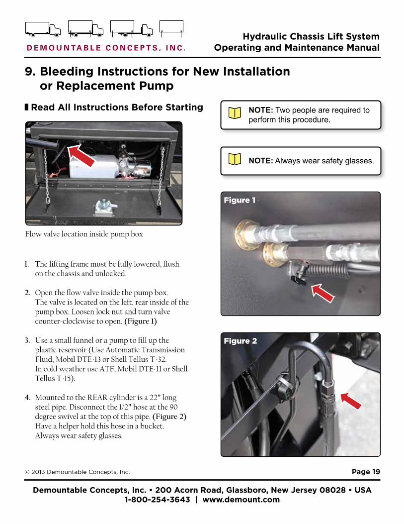
1. The lifting frame must be fully lowered, flush on the chassis and unlocked.
2. Open the flow valve inside the pump box. The valve is located on the left, rear inside of the pump box. Loosen lock nut and turn valve counter-clockwise to open. (Figure 1)
3. Use a small funnel or a pump to fill up the plastic reservoir (Use Automatic Transmission Fluid, Mobil DTE-13 or Shell Tellus T-32. In cold weather use ATF, Mobil DTE-11 or Shell Tellus T-15).
4. Mounted to the REAR cylinder is a 22" long steel pipe. Disconnect the 1/2" hose at the 90 degree swivel at the top of this pipe. (Figure 2) Have a helper hold this hose in a bucket. Always wear safety glasses.
NOTE: Two people are required to perform this procedure.
9. Bleeding Instructions for New Installation or Replacement Pump
¦ Read All Instructions Before Starting
Flow valve location inside pump box
Figure 1
Figure 2
NOTE: Always wear safety glasses.
Demountable Concepts, Inc. • 200 Acorn Road, Glassboro, New Jersey 08028 • USA 1-800-254-3643 | www.demount.com
Hydraulic Chassis Lift System Operating and Maintenance Manual
Page 20© 2013 Demountable Concepts, Inc.
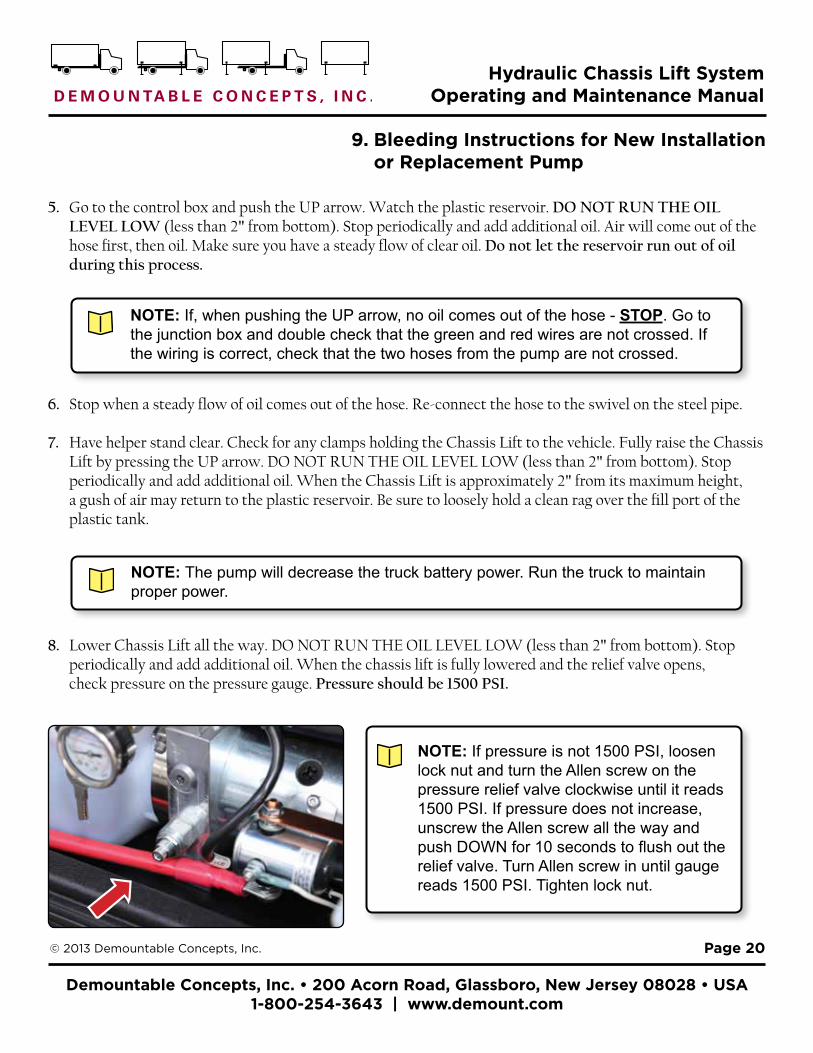
5. Go to the control box and push the UP arrow. Watch the plastic reservoir. DO NOT RUN THE OIL LEVEL LOW (less than 2" from bottom). Stop periodically and add additional oil. Air will come out of the hose first, then oil. Make sure you have a steady flow of clear oil. Do not let the reservoir run out of oil during this process.
9. Bleeding Instructions for New Installation or Replacement Pump
NOTE: If pressure is not 1500 PSI, loosen lock nut and turn the Allen screw on the pressure relief valve clockwise until it reads 1500 PSI. If pressure does not increase, unscrew the Allen screw all the way and push DOWN for 10 seconds to flush out the relief valve. Turn Allen screw in until gauge reads 1500 PSI. Tighten lock nut.
NOTE: If, when pushing the UP arrow, no oil comes out of the hose - STOP. Go to the junction box and double check that the green and red wires are not crossed. If the wiring is correct, check that the two hoses from the pump are not crossed.
6. Stop when a steady flow of oil comes out of the hose. Re-connect the hose to the swivel on the steel pipe.
7. Have helper stand clear. Check for any clamps holding the Chassis Lift to the vehicle. Fully raise the Chassis Lift by pressing the UP arrow. DO NOT RUN THE OIL LEVEL LOW (less than 2" from bottom). Stop periodically and add additional oil. When the Chassis Lift is approximately 2" from its maximum height, a gush of air may return to the plastic reservoir. Be sure to loosely hold a clean rag over the fill port of the plastic tank.
NOTE: The pump will decrease the truck battery power. Run the truck to maintain proper power.
8. Lower Chassis Lift all the way. DO NOT RUN THE OIL LEVEL LOW (less than 2" from bottom). Stop periodically and add additional oil. When the chassis lift is fully lowered and the relief valve opens, check pressure on the pressure gauge. Pressure should be 1500 PSI.

Demountable Concepts, Inc. • 200 Acorn Road, Glassboro, New Jersey 08028 • USA 1-800-254-3643 | www.demount.com
Hydraulic Chassis Lift System Operating and Maintenance Manual
Page 21© 2013 Demountable Concepts, Inc.
9. Fully raise the Chassis Lift by pushing the UP arrow on the lifter controller.
10. IMPORTANT: Be sure to return to the pump box to set the flow valve. The valve must be set so that the Chassis Lift lowers SLOWER than it raises or oil will overflow. The pressure gauge should read approximately 350 PSI without a body on the chassis. Tighten the lock nut.
11. When the Chassis Lift is lowered, be sure it is sitting on top of the front mounts. When fully lowered, any air space here will indicate air is trapped in the top of the front cylinder.
9. Bleeding Instructions for New Installation or Replacement Pump (Cont.)
NOTE: If you feel the need to re-bleed the system because the unit will not fully lower onto the chassis, follow our standard bleeding instructions in section 10.
Demountable Concepts, Inc. • 200 Acorn Road, Glassboro, New Jersey 08028 • USA 1-800-254-3643 | www.demount.com
Hydraulic Chassis Lift System Operating and Maintenance Manual
Page 22© 2013 Demountable Concepts, Inc.
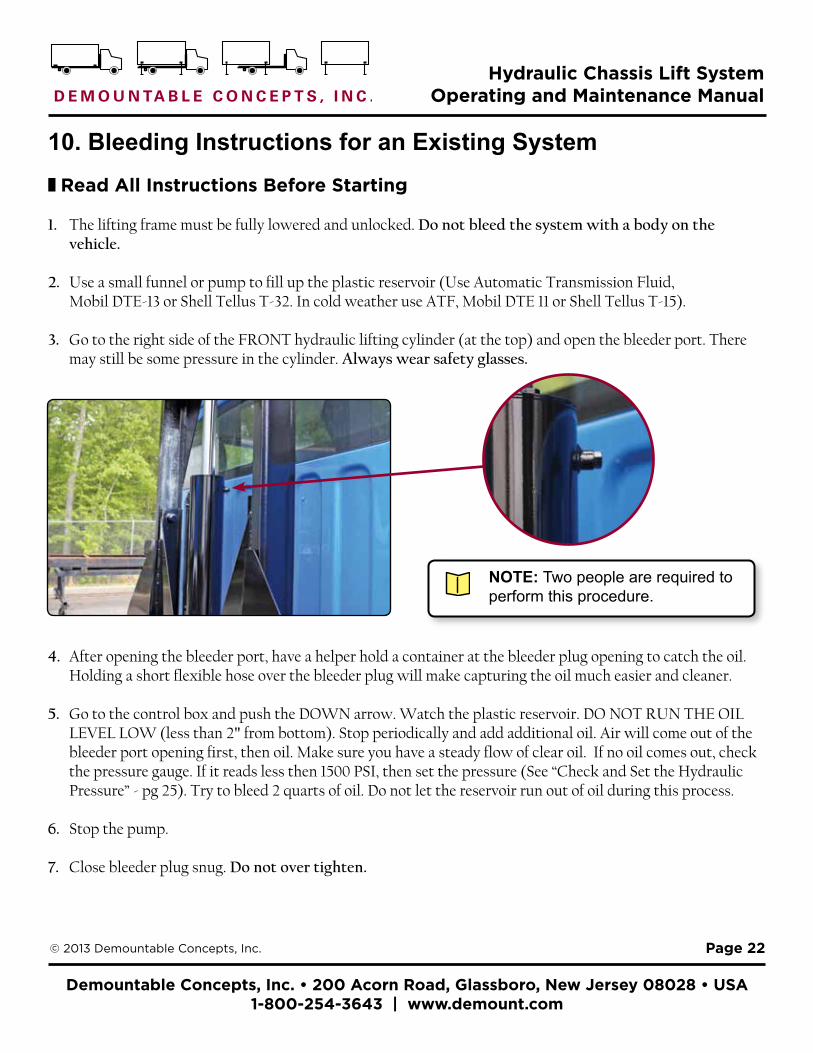
10. Bleeding Instructions for an Existing System¦ Read All Instructions Before Starting
1. The lifting frame must be fully lowered and unlocked. Do not bleed the system with a body on the vehicle.
2. Use a small funnel or pump to fill up the plastic reservoir (Use Automatic Transmission Fluid, Mobil DTE-13 or Shell Tellus T-32. In cold weather use ATF, Mobil DTE 11 or Shell Tellus T-15).
3. Go to the right side of the FRONT hydraulic lifting cylinder (at the top) and open the bleeder port. There may still be some pressure in the cylinder. Always wear safety glasses.
4. After opening the bleeder port, have a helper hold a container at the bleeder plug opening to catch the oil. Holding a short flexible hose over the bleeder plug will make capturing the oil much easier and cleaner.
5. Go to the control box and push the DOWN arrow. Watch the plastic reservoir. DO NOT RUN THE OIL LEVEL LOW (less than 2" from bottom). Stop periodically and add additional oil. Air will come out of the bleeder port opening first, then oil. Make sure you have a steady flow of clear oil. If no oil comes out, check the pressure gauge. If it reads less then 1500 PSI, then set the pressure (See “Check and Set the Hydraulic Pressure” - pg 25). Try to bleed 2 quarts of oil. Do not let the reservoir run out of oil during this process.
6. Stop the pump.
7. Close bleeder plug snug. Do not over tighten.
NOTE: Two people are required to perform this procedure.
Demountable Concepts, Inc. • 200 Acorn Road, Glassboro, New Jersey 08028 • USA 1-800-254-3643 | www.demount.com
Hydraulic Chassis Lift System Operating and Maintenance Manual
Page 23© 2013 Demountable Concepts, Inc.
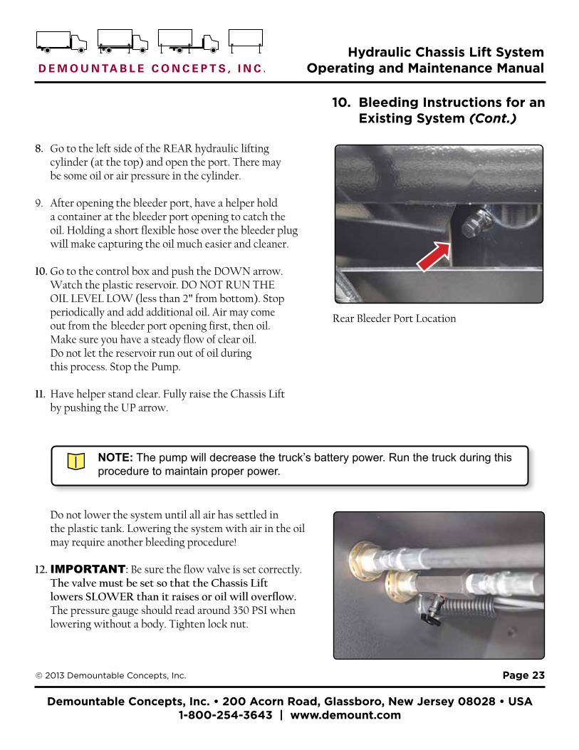
8. Go to the left side of the REAR hydraulic lifting cylinder (at the top) and open the port. There may be some oil or air pressure in the cylinder.
9. After opening the bleeder port, have a helper hold a container at the bleeder port opening to catch the oil. Holding a short flexible hose over the bleeder plug will make capturing the oil much easier and cleaner.
10. Go to the control box and push the DOWN arrow. Watch the plastic reservoir. DO NOT RUN THE OIL LEVEL LOW (less than 2" from bottom). Stop periodically and add additional oil. Air may come out from the bleeder port opening first, then oil. Make sure you have a steady flow of clear oil. Do not let the reservoir run out of oil during this process. Stop the Pump.
11. Have helper stand clear. Fully raise the Chassis Lift by pushing the UP arrow.
10. Bleeding Instructions for an Existing System (Cont.)
NOTE: The pump will decrease the truck’s battery power. Run the truck during this procedure to maintain proper power.
Do not lower the system until all air has settled in the plastic tank. Lowering the system with air in the oil may require another bleeding procedure!
12. IMPORTANT: Be sure the flow valve is set correctly. The valve must be set so that the Chassis Lift lowers SLOWER than it raises or oil will overflow. The pressure gauge should read around 350 PSI when lowering without a body. Tighten lock nut.
Rear Bleeder Port Location

Demountable Concepts, Inc. • 200 Acorn Road, Glassboro, New Jersey 08028 • USA 1-800-254-3643 | www.demount.com
Hydraulic Chassis Lift System Operating and Maintenance Manual
Page 24© 2013 Demountable Concepts, Inc.
13. When the Chassis Lift is lowered, be sure it is sitting on top of the front mounts. When fully lowered, any air space here will indicate air is trapped in the top of the front cylinder.
NOTE: If you think you have an air-bleeding problem PLEASE carefully check if air or frothy oil comes out of the front bleeder port during initial bleeding. If you have repeated problems and only oil comes out, please call Demountable Concepts, Inc. at 1-800-254-3643.
NOTE: If you are installing a new Chassis Lift, a new pump, and a new cylinder or have lost a major amount of oil, please call Demountable Concepts, Inc. at 1-800-254-3643 for a different set of bleeding instructions.
NOTE: This procedure may have to be done two or three times.
10. Bleeding Instructions for an Existing System (Cont.)
Demountable Concepts, Inc. • 200 Acorn Road, Glassboro, New Jersey 08028 • USA 1-800-254-3643 | www.demount.com
Hydraulic Chassis Lift System Operating and Maintenance Manual
Page 25© 2013 Demountable Concepts, Inc.
¦ Read All Instructions Before Starting
1. The lifting frame must be fully lowered and unlocked.
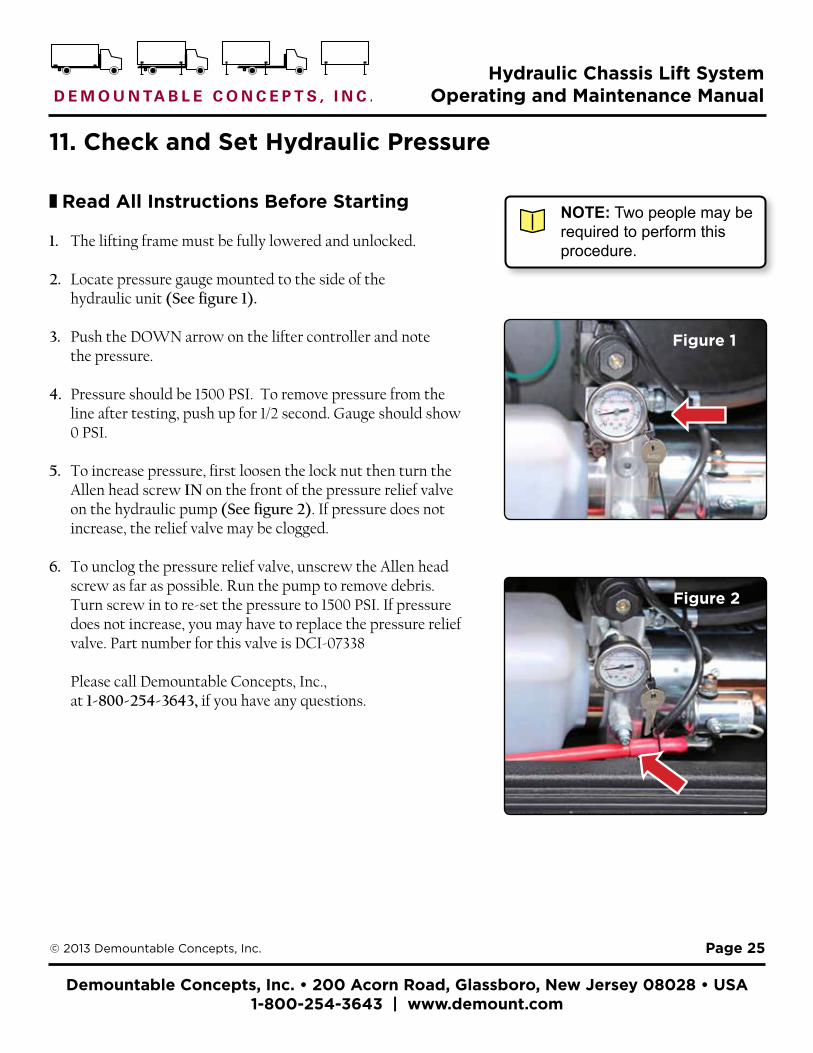
2. Locate pressure gauge mounted to the side of the hydraulic unit (See figure 1).
3. Push the DOWN arrow on the lifter controller and note the pressure.
4. Pressure should be 1500 PSI. To remove pressure from the line after testing, push up for 1/2 second. Gauge should show 0 PSI.
5. To increase pressure, first loosen the lock nut then turn the Allen head screw IN on the front of the pressure relief valve on the hydraulic pump (See figure 2). If pressure does not increase, the relief valve may be clogged.
6. To unclog the pressure relief valve, unscrew the Allen head screw as far as possible. Run the pump to remove debris. Turn screw in to re-set the pressure to 1500 PSI. If pressure does not increase, you may have to replace the pressure relief valve. Part number for this valve is DCI-07338
Please call Demountable Concepts, Inc., at 1-800-254-3643, if you have any questions.
11. Check and Set Hydraulic Pressure
NOTE: Two people may be required to perform this procedure.
Figure 1
Figure 2
Demountable Concepts, Inc. • 200 Acorn Road, Glassboro, New Jersey 08028 • USA 1-800-254-3643 | www.demount.com
Hydraulic Chassis Lift System Operating and Maintenance Manual
Page 26© 2013 Demountable Concepts, Inc.
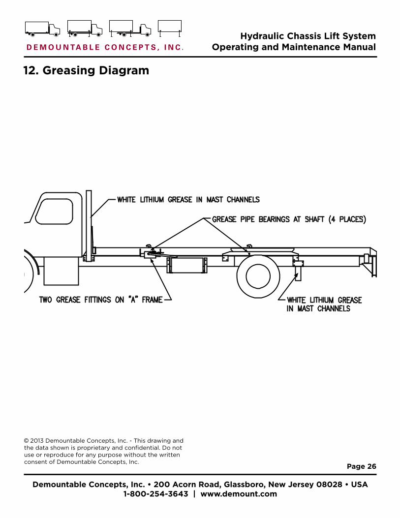
12. Greasing Diagram
© 2013 Demountable Concepts, Inc. - This drawing and the data shown is proprietary and confidential. Do not use or reproduce for any purpose without the written consent of Demountable Concepts, Inc.
Demountable Concepts, Inc. • 200 Acorn Road, Glassboro, New Jersey 08028 • USA 1-800-254-3643 | www.demount.com
Hydraulic Chassis Lift System Operating and Maintenance Manual
Page 27© 2013 Demountable Concepts, Inc.
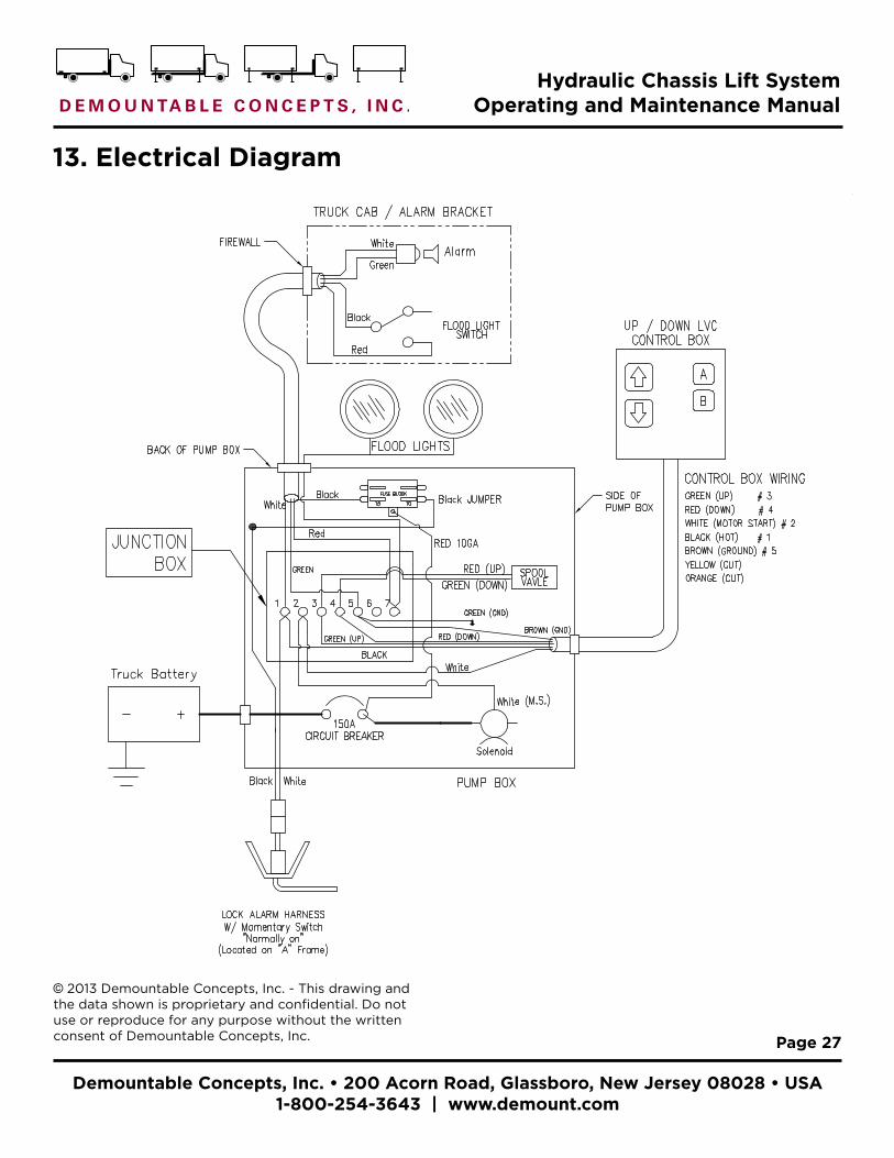
13. Electrical Diagram
© 2013 Demountable Concepts, Inc. - This drawing and the data shown is proprietary and confidential. Do not use or reproduce for any purpose without the written consent of Demountable Concepts, Inc.
Demountable Concepts, Inc. • 200 Acorn Road, Glassboro, New Jersey 08028 • USA 1-800-254-3643 | www.demount.com
Hydraulic Chassis Lift System Operating and Maintenance Manual
Page 28© 2013 Demountable Concepts, Inc.
14. 4-Way Light Plug Wiring Diagram
© 2013 Demountable Concepts, Inc. - This drawing and the data shown is proprietary and confidential. Do not use or reproduce for any purpose without the written consent of Demountable Concepts, Inc.

Demountable Concepts, Inc. • 200 Acorn Road, Glassboro, New Jersey 08028 • USA 1-800-254-3643 | www.demount.com
Hydraulic Chassis Lift System Operating and Maintenance Manual
Page 29© 2013 Demountable Concepts, Inc.
15. Pump Unit Diagram
3/4"19
6 11/16"170
20 7/8"530
DRAIN HOLE REF
11
15
21 SHIP LOOSE
1 BASE-12086
191210 14
132526
(PLASTIC PLUG)
1716
"A" COIL (GREEN WIRE)
"B" COIL (RED WIRE)
24
18
RELIEF VALVE(01316-FILTER REF13090-RETAINING SPRING REF)
2
69
8
3
20 SEE NOTE #1
7
54
"A" OUTLET PORT9/16-18 SAE #6(STEEL PLUG REF)
"B" OUTLET PORT9/16-18 SAE #6(STEEL PLUG REF)
VIEW SHOWN WITHOUT RESERVOIR
C1C1
1 5/8"41
3 1/4"83 2 MOUNTING HOLES
3/8-16 UNC-2B
"A" OUTLET PORT9/16-18 SAE #6(STEEL PLUG REF)
"B" OUTLET PORT9/16-18 SAE #6(STEEL PLUG REF)
RED WIRE (ATTACH TO "B" COIL)GREEN WIRE (ATTACH TO "A" COIL)WHITE WIRE (ATTACH TO WHITE WIREFROM MOTOR START SOLENOID)
23 WIRE TO UNIT
22 WIRE TO UNITWHITE WIRE (ATTACH TOSOLENOID START POST)
NOTES:
1. CLAMP-07900 MUST BE INSTALLED AT THIS LOCATION.
CONNECT THRU "B" COIL STRAIN RELIEF
WHITE WIRE,CONNECT THRU "A" COIL STRAIN RELIEF
ITEM NO QTY. PART NO DESCRIPTION1 1 12628 BASE ASSY,M3598,MOD,STD MTR/MT2 1 12630-510 P ASSY,QM,MDLR,DC,BRG RSV,1/2"3 4 07837 SCREW,SHC,1/4-20 X 3.25,BLK OX4 1 07959 NIPPLE,1/2 NPT X 2,SCH 405 1 13109 FITTING,ELBOW,90 DEG,PIPE,BLCK6 1 13015 FILTER,SUCTION,1/2"7 1 01116 NIPPLE,1/4 X 68 1 01222 ELBOW,90 DEG 1/4NPT X 1/4 NPT9 1 03212-03.00 TUBE,RTN,STR,1/4 NPT,PVC10 2 00118 O-RING,0.63 X 0.75 X 0.06 -01611 1 07308 MANIFOLD,D03,1 STA,VLV,M-350012 3 07739 SCREW,SHC,1/4-20 X 1.50,BLK OX13 1 00961-Y VALVE,ELEC,12VDC,4W/3P,D03,CC14 4 03276 PLUG,SAE O-RING,9/16-18,HEX,SO15 1 08111-S MOTOR,DC,12V,4.5",1 TERM16 1 03427 SWITCH,SOL,12VDC,3-POST,M-SER17 1 01349 STRAP,MOTOR-SOLENOID CONNECT18 2 17071 SCREW,PAN HD,TORX,10-32 X 5/1619 1 14158 RESV,PLASTIC,5.5X6.5X13.520 1 07900 CLAMP,HOSE,WORM GEAR,RSV,M-SER21 1 01143 PLUG,RESEV,BREATHER-FILLER22 1 17906-015 CORD ASSY,HRNSS,WHT WIRE,15"LG23 1 17907-024 CORD ASSY,HRNSS,3 WIRE,24"LG24 2 01531 FITTING,STRN.REL.WP 3/8" CORD 25 1 18266 STRAP,CONNECT PLATE,D03 VLV26 1 01339 TERMINAL,CLS END CONNECT,SMALL
M-3515-0117 REV: -
Demountable Concepts, Inc. • 200 Acorn Road, Glassboro, New Jersey 08028 • USA 1-800-254-3643 | www.demount.com
Hydraulic Chassis Lift System Operating and Maintenance Manual
Page 30© 2013 Demountable Concepts, Inc.
16. Hook Measurement Drawing
© 2013 Demountable Concepts, Inc. - This drawing and the data shown is proprietary and confidential. Do not use or reproduce for any purpose without the written consent of Demountable Concepts, Inc.
Demountable Concepts, Inc. • 200 Acorn Road, Glassboro, New Jersey 08028 • USA 1-800-254-3643 | www.demount.com
Hydraulic Chassis Lift System Operating and Maintenance Manual
Page 31© 2013 Demountable Concepts, Inc.
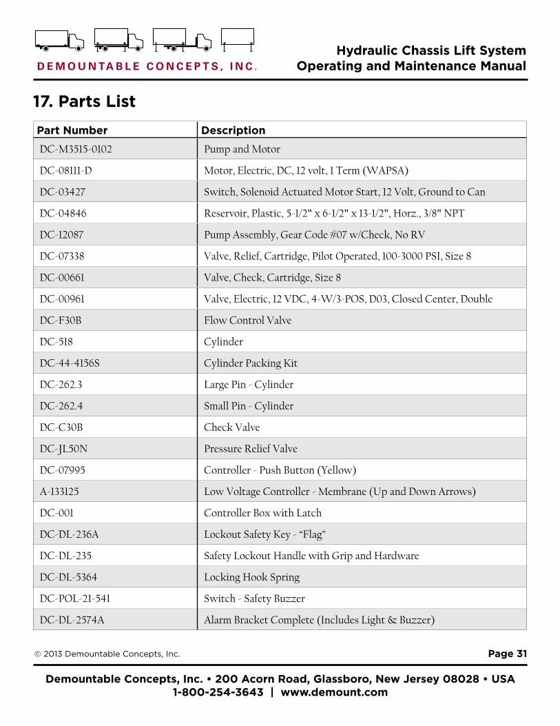
Part Number Description
DC-M3515-0102 Pump and Motor
DC-08111-D Motor, Electric, DC, 12 volt, 1 Term (WAPSA)
DC-03427 Switch, Solenoid Actuated Motor Start, 12 Volt, Ground to Can
DC-04846 Reservoir, Plastic, 5-1/2" x 6-1/2" x 13-1/2", Horz., 3/8" NPT
DC-12087 Pump Assembly, Gear Code #07 w/Check, No RV
DC-07338 Valve, Relief, Cartridge, Pilot Operated, 100-3000 PSI, Size 8
DC-00661 Valve, Check, Cartridge, Size 8
DC-00961 Valve, Electric, 12 VDC, 4-W/3-POS, D03, Closed Center, Double
DC-F30B Flow Control Valve
DC-518 Cylinder
DC-44-4156S Cylinder Packing Kit
DC-262.3 Large Pin - Cylinder
DC-262.4 Small Pin - Cylinder
DC-C30B Check Valve
DC-JL50N Pressure Relief Valve
DC-07995 Controller - Push Button (Yellow)
A-133125 Low Voltage Controller - Membrane (Up and Down Arrows)
DC-001 Controller Box with Latch
DC-DL-236A Lockout Safety Key - “Flag”
DC-DL-235 Safety Lockout Handle with Grip and Hardware
DC-DL-5364 Locking Hook Spring
DC-POL-21-541 Switch - Safety Buzzer
DC-DL-2574A Alarm Bracket Complete (Includes Light & Buzzer)
17. Parts List

Demountable Concepts, Inc. • 200 Acorn Road, Glassboro, New Jersey 08028 • USA 1-800-254-3643 | www.demount.com
Hydraulic Chassis Lift System Operating and Maintenance Manual
Page 32© 2013 Demountable Concepts, Inc.
Part Number Description
DC-DL-2001 Lock Warning Upgrade Kit
DC-306 Back-up Alarm
DC-1235 Light Plug, 4-Way
DC-1232 Light Plug Receptacle, 4-Way
DC-12082 Light Plug, 7-Way
DC-12080-01 Light Plug Receptacle, 7-Way
DCI-DL-215-84 Linkage Rod (for 96" Locking Bar)
DCI-DL-215-120 Linkage Rod (for 132" Locking Bar)
DC-100R200PCL Linkage Rod Pin
DC-L4133 Complete Leg
DC-L4133UO Upper leg Assembly ONLY
DC-L4133LO Lower Leg Assembly ONLY
DC-100S Small Leg Pin (Lower)
DC-106S Large Leg Pin (Upper)
DC-103S Leg Pin Chain
DC-7350-6N Quick Links
DC-N170VB Body End Caps (“Scrubber Plates”)
DC-DL-262 Chassis Mounted Side Guides
DC-B-2003 Lift Gate Remote Control
DC-B-2003-1 Lift Gate Remote Control - Handle Only
17. Parts (Cont.)

Demountable Concepts, Inc. • 200 Acorn Road, Glassboro, New Jersey 08028 • USA 1-800-254-3643 | www.demount.com
Hydraulic Chassis Lift System Operating and Maintenance Manual
Page 33© 2013 Demountable Concepts, Inc.
¦ For Service and Parts:
Phone: 1-800-254-3643Fax: 856-863-6704E-mail: [email protected]: www.demount.com Demountable Concepts, Inc. 200 Acorn Road Glassboro, NJ 08028 USA
18. Contact Information for Service and Parts
NOTE: To preview, or order parts online visit www.dciparts.comClick on the Demountable Parts link.
Rev. 1-12_20_13