Embed Size (px)
Citation preview
1Scientific RepoRts | 7:45549 | DOI: 10.1038/srep45549
www.nature.com/scientificreports
Demonstration of a Three-dimensional Negative Index Medium Operated at Multiple-angle Incidences by Monolithic Metallic Hemispherical ShellsTing-Tso Yeh1,*, Tsung-Yu Huang1,*, Takuo Tanaka3,4,5 & Ta-Jen Yen1,2
We design and construct a three-dimensional (3D) negative index medium (NIM) composed of gold hemispherical shells to supplant an integration of a split-ring resonator and a discrete plasmonic wire for both negative permeability and permittivity at THz gap. With the proposed highly symmetric gold hemispherical shells, the negative index is preserved at multiple incident angles ranging from 0° to 85° for both TE and TM waves, which is further evidenced by negative phase flows in animated field distributions and outweighs conventional fishnet structures with operating frequency shifts when varying incident angles. Finally, the fabrication of the gold hemispherical shells is facilitated via standard UV lithographic and isotropic wet etching processes and characterized by μ-FTIR. The measurement results agree the simulated ones very well.
The advent of negative index media (NIM)1,2 with non-existing material properties in nature has triggered a rev-olution in the field of electromagnetics and then enabled various intriguing applications such as perfect lenses3,4, negative Goos-Hänchen effect based slowing light systems5,6 and perfect absorbers7. The early demonstration of an NIM1,2 was realized via the combination of negative permeability from split-ring resonators (SRRs)8,9 and negative permittivity from plasmonic wires10. Yet, such combination is experimentally infeasible at a frequency higher than the microwave region and appears sensitive to the angle and polarization of the incident excita-tion. To ease the burden of fabrication and the limitation of polarization, a fishnet structure is introduced with intensive investigations by now11–13. The double negative identities of a fishnet structure, however, still suffer from the sensitivity of incident angles, for example, 8-degree off normal incidence alters the performance of the fishnet structure entirely13. Therefore, researchers are still eager to unravel such hindrance for an NIM operated under multiple incident angles beyond the microwave region. A rational solution is a three-dimensional (3D) NIM. There appear a few incumbent approaches to 3D NIMs, such as implementing six planar SRRs on six sur-faces of a cube with orthogonally crossing continuous plasmonic wires embedded in a substrate14 and merging multi-directional V-shaped magnetic resonators and sphere-shaped electric resonators into a monolithic struc-ture15. Nonetheless, both of the 3D NIMs confront the complexity of practical realization.
To resolve such circumscription, in this work we demonstrate a simple 3D NIM composed of an array of mon-olithic metallic hemispherical shells, which allows both negative permeability and negative permittivity under multiple-angle incidences within the THz gap. Besides, the employment of the metallic hemispherical shell guar-antees a polarization independent response due to its circular symmetry under normal-incidence excitation. Most importantly, different from the antecedent 3D NIM14,15, such a metallic hemispherical shell array can be easily fabricated through standard UV lithographic and isotropic wet etching processes and will readily advance a variety of THz applications16,17.
1Department of Materials Science and Engineering, National Tsing Hua University, Hsinchu, Taiwan, ROC. 2Department of Materials Science Center for Nanotechnology, Materials Science, and Microsystems, National Tsing Hua University, Hsinchu, Taiwan, ROC. 3Metamaterials Laboratory, RIKEN, Saitama 351-0198, Japan. 4RIKEN Center for Advanced Photonics, RIKEN, Saitama 351-0198, Japan. 5Tokyo Institute of Technology, Kanagawa 226-8503, Japan. *These authors contributed equally to this work. Correspondence and requests for materials should be addressed to T.-J.Y. (email: [email protected])
Received: 21 November 2016
accepted: 01 March 2017
Published: 07 April 2017
OPEN
www.nature.com/scientificreports/
2Scientific RepoRts | 7:45549 | DOI: 10.1038/srep45549
Simulation Methods and Experiment ProcedureTo verify our design strategy, we employ a finite-integration solver of CST Microwave StudioTM, to calculate the complex scattering parameters of our proposed 3D NIM and then examine the retrieval results from the effective medium theory18, surface currents and phase propagation directions as well to affirm that our proposed structure possesses negative index under normal and oblique incidences.
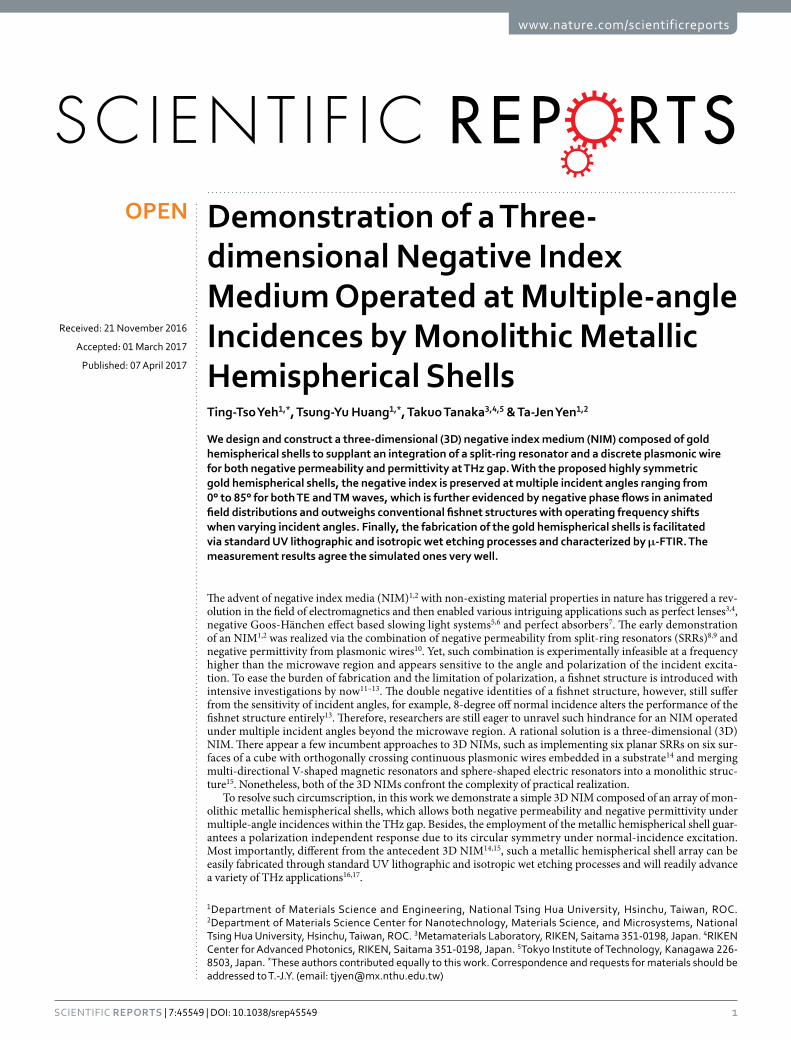
As for the fabrication of the 3D NIM, one can follow procedures as illustrated in Fig. 1. First, we spun a layer of 1.8-μ m-thick photoresist (AZ5214) on a silicon substrate with silicon nitride/silicon oxide (500 nm/100 nm) as a mask to protect the substrate from etching, and a designed pattern, a circle with a 5-μ m-wide diameter, is intro-duced onto the photoresist by standard UV lithographic process. Reactive ion etching (RIE) is utilized to remove silicon nitride/silicon oxide, and the sample was then dipped into an HNA (hydrofluoric acid, nitric acid, and acetic acid) solution with an etching rate of around 3.17 μ m/min. After HNA etching, we can obtain a hemispher-ical cavity with a 34.17 ± 0.52-μ m-wide diameter and then the residual silicon nitride/silicon oxide is removed by dipping the sample into 49 wt% hydrofluoric acid. In the following, we deposited a continuous 100-nm-thick gold film by an electron beam evaporator. Note that before depositing a gold film, the sample is dipped into 69 wt% nitric acid for 4 hours in order to form a thin layer of silicon oxide, which can benefit the following peeling off process. Afterward, we stuck a tape on the top surface of the sample and peeled off the gold film on the surface but left gold well-attached to the hemispherical cavity; finally, we utilized HNA to etch the back of the supporting silicon substrate down to 50-μ m, thus completing the fabrication process of the gold hemispherical shells.
Finally, we utilized a micro Fourier transform infrared spectrometer (Bruker Vertex 70 V μ -FTIR) to measure the relative transmission of the fabricated samples at 0°, 15° and 30° incidences by our homemade stage. These samples were illuminated by a mercury lamp through an aperture of 8 mm in diameter, and a PE/DTGS detector was placed on the opposite side to collect the transmitted signals. All measurements were done in vacuum to reduce the noise from the ambient environment including absorption by moisture and air.
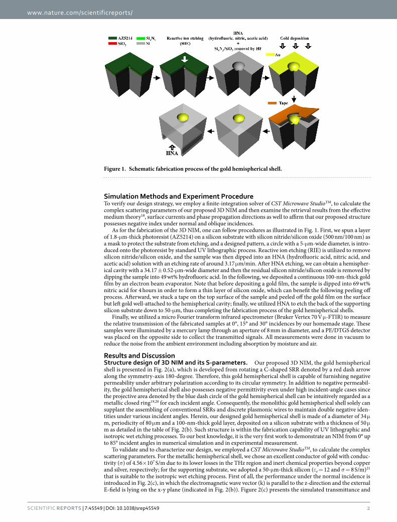
Results and DiscussionStructure design of 3D NIM and its S-parameters. Our proposed 3D NIM, the gold hemispherical shell is presented in Fig. 2(a), which is developed from rotating a C-shaped SRR denoted by a red dash arrow along the symmetry-axis 180-degree. Therefore, this gold hemispherical shell is capable of furnishing negative permeability under arbitrary polarization according to its circular symmetry. In addition to negative permeabil-ity, the gold hemispherical shell also possesses negative permittivity even under high incident-angle cases since the projective area denoted by the blue dash circle of the gold hemispherical shell can be intuitively regarded as a metallic closed ring19,20 for each incident angle. Consequently, the monolithic gold hemispherical shell solely can supplant the assembling of conventional SRRs and discrete plasmonic wires to maintain double negative iden-tities under various incident angles. Herein, our designed gold hemispherical shell is made of a diameter of 34 μ m, periodicity of 80 μ m and a 100-nm-thick gold layer, deposited on a silicon substrate with a thickness of 50 μ m as detailed in the table of Fig. 2(b). Such structure is within the fabrication capability of UV lithographic and isotropic wet etching processes. To our best knowledge, it is the very first work to demonstrate an NIM from 0° up to 85° incident angles in numerical simulation and in experimental measurement.
To validate and to characterize our design, we employed a CST Microwave StudioTM, to calculate the complex scattering parameters. For the metallic hemispherical shell, we chose an excellent conductor of gold with conduc-tivity (σ ) of 4.56× 10⁷ S/m due to its lower losses in the THz region and inert chemical properties beyond copper and silver, respectively; for the supporting substrate, we adopted a 50-μ m-thick silicon (ε r = 12 and σ = 8 S/m)21 that is suitable to the isotropic wet etching process. First of all, the performance under the normal incidence is introduced in Fig. 2(c), in which the electromagnetic wave vector (k) is parallel to the z-direction and the external E-field is lying on the x-y plane (indicated in Fig. 2(b)). Figure 2(c) presents the simulated transmittance and
Figure 1. Schematic fabrication process of the gold hemispherical shell.
www.nature.com/scientificreports/
3Scientific RepoRts | 7:45549 | DOI: 10.1038/srep45549
reflectance spectra, indicated by blue solid and red dot lines, respectively. There appears a transmittance dip at the frequency of 1.149 THz, gradually elevating to a transmittance apex at 1.185 THz, where we expect to observe double negative identities13–15.
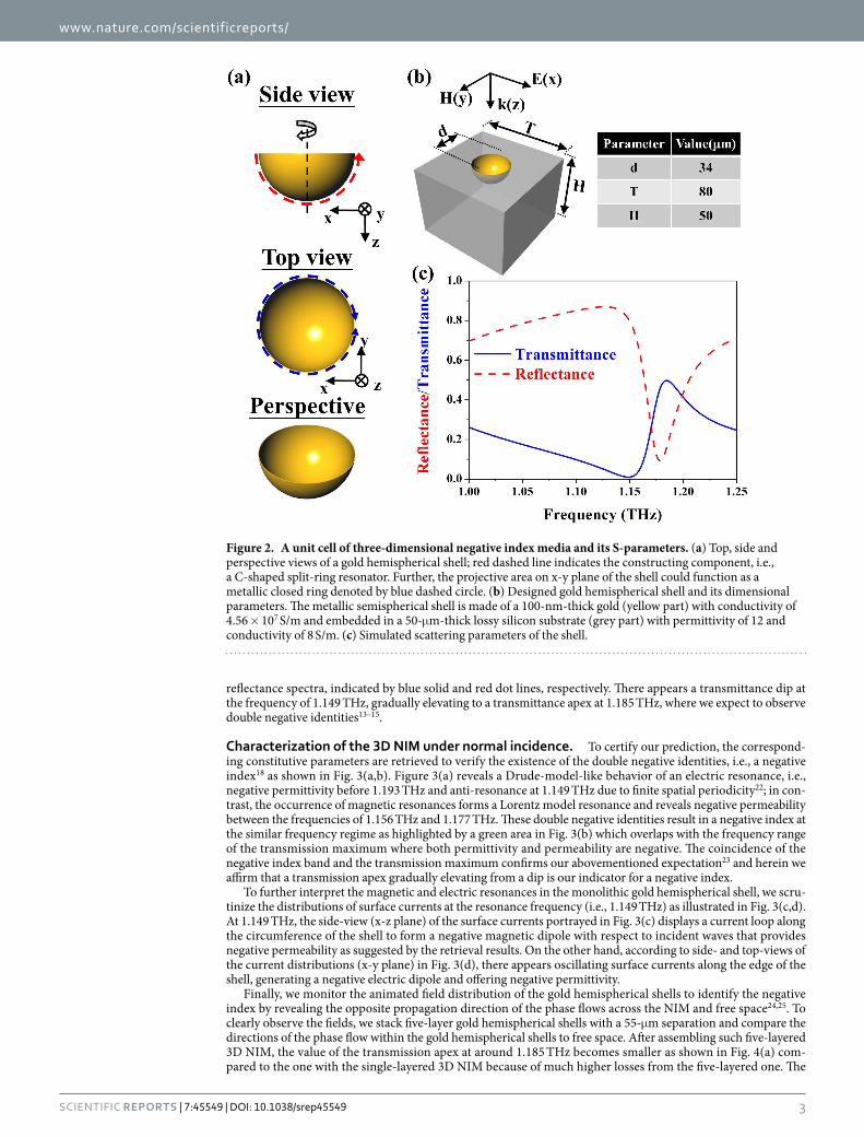
Characterization of the 3D NIM under normal incidence. To certify our prediction, the correspond-ing constitutive parameters are retrieved to verify the existence of the double negative identities, i.e., a negative index18 as shown in Fig. 3(a,b). Figure 3(a) reveals a Drude-model-like behavior of an electric resonance, i.e., negative permittivity before 1.193 THz and anti-resonance at 1.149 THz due to finite spatial periodicity22; in con-trast, the occurrence of magnetic resonances forms a Lorentz model resonance and reveals negative permeability between the frequencies of 1.156 THz and 1.177 THz. These double negative identities result in a negative index at the similar frequency regime as highlighted by a green area in Fig. 3(b) which overlaps with the frequency range of the transmission maximum where both permittivity and permeability are negative. The coincidence of the negative index band and the transmission maximum confirms our abovementioned expectation23 and herein we affirm that a transmission apex gradually elevating from a dip is our indicator for a negative index.
To further interpret the magnetic and electric resonances in the monolithic gold hemispherical shell, we scru-tinize the distributions of surface currents at the resonance frequency (i.e., 1.149 THz) as illustrated in Fig. 3(c,d). At 1.149 THz, the side-view (x-z plane) of the surface currents portrayed in Fig. 3(c) displays a current loop along the circumference of the shell to form a negative magnetic dipole with respect to incident waves that provides negative permeability as suggested by the retrieval results. On the other hand, according to side- and top-views of the current distributions (x-y plane) in Fig. 3(d), there appears oscillating surface currents along the edge of the shell, generating a negative electric dipole and offering negative permittivity.
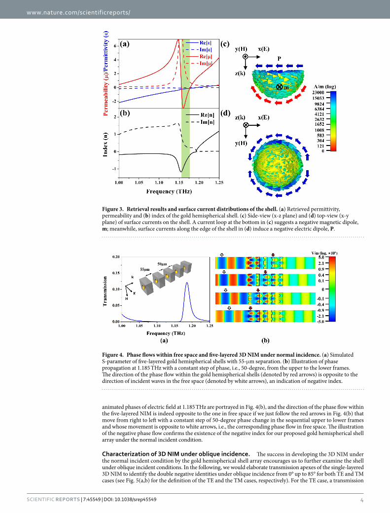
Finally, we monitor the animated field distribution of the gold hemispherical shells to identify the negative index by revealing the opposite propagation direction of the phase flows across the NIM and free space24,25. To clearly observe the fields, we stack five-layer gold hemispherical shells with a 55-μ m separation and compare the directions of the phase flow within the gold hemispherical shells to free space. After assembling such five-layered 3D NIM, the value of the transmission apex at around 1.185 THz becomes smaller as shown in Fig. 4(a) com-pared to the one with the single-layered 3D NIM because of much higher losses from the five-layered one. The
Figure 2. A unit cell of three-dimensional negative index media and its S-parameters. (a) Top, side and perspective views of a gold hemispherical shell; red dashed line indicates the constructing component, i.e., a C-shaped split-ring resonator. Further, the projective area on x-y plane of the shell could function as a metallic closed ring denoted by blue dashed circle. (b) Designed gold hemispherical shell and its dimensional parameters. The metallic semispherical shell is made of a 100-nm-thick gold (yellow part) with conductivity of 4.56 × 10⁷ S/m and embedded in a 50-μ m-thick lossy silicon substrate (grey part) with permittivity of 12 and conductivity of 8 S/m. (c) Simulated scattering parameters of the shell.
www.nature.com/scientificreports/
4Scientific RepoRts | 7:45549 | DOI: 10.1038/srep45549
animated phases of electric field at 1.185 THz are portrayed in Fig. 4(b), and the direction of the phase flow within the five-layered NIM is indeed opposite to the one in free space if we just follow the red arrows in Fig. 4(b) that move from right to left with a constant step of 50-degree phase change in the sequential upper to lower frames and whose movement is opposite to white arrows, i.e., the corresponding phase flow in free space. The illustration of the negative phase flow confirms the existence of the negative index for our proposed gold hemispherical shell array under the normal incident condition.
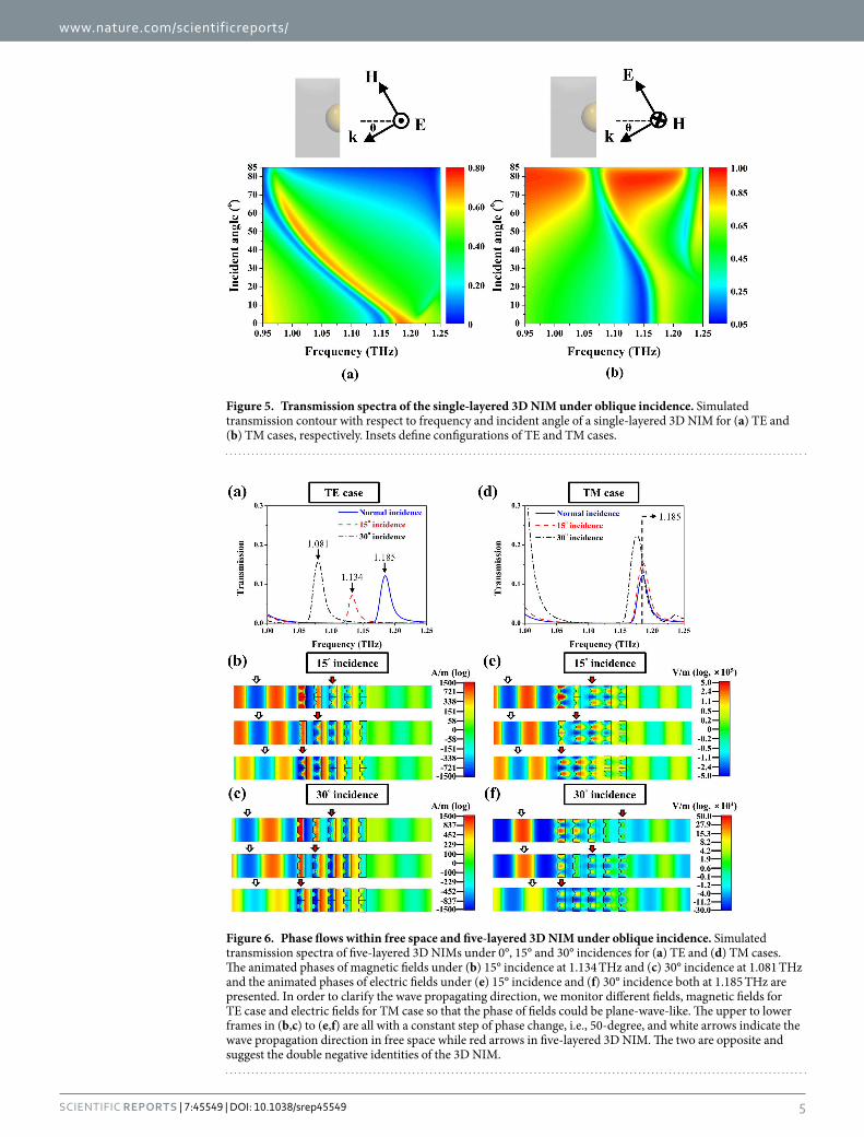
Characterization of 3D NIM under oblique incidence. The success in developing the 3D NIM under the normal incident condition by the gold hemispherical shell array encourages us to further examine the shell under oblique incident conditions. In the following, we would elaborate transmission apexes of the single-layered 3D NIM to identify the double negative identities under oblique incidence from 0° up to 85° for both TE and TM cases (see Fig. 5(a,b) for the definition of the TE and the TM cases, respectively). For the TE case, a transmission
Figure 3. Retrieval results and surface current distributions of the shell. (a) Retrieved permittivity, permeability and (b) index of the gold hemispherical shell. (c) Side-view (x-z plane) and (d) top-view (x-y plane) of surface currents on the shell. A current loop at the bottom in (c) suggests a negative magnetic dipole, m; meanwhile, surface currents along the edge of the shell in (d) induce a negative electric dipole, P.
Figure 4. Phase flows within free space and five-layered 3D NIM under normal incidence. (a) Simulated S-parameter of five-layered gold hemispherical shells with 55-μ m separation. (b) Illustration of phase propagation at 1.185 THz with a constant step of phase, i.e., 50-degree, from the upper to the lower frames. The direction of the phase flow within the gold hemispherical shells (denoted by red arrows) is opposite to the direction of incident waves in the free space (denoted by white arrows), an indication of negative index.
www.nature.com/scientificreports/
5Scientific RepoRts | 7:45549 | DOI: 10.1038/srep45549
Figure 5. Transmission spectra of the single-layered 3D NIM under oblique incidence. Simulated transmission contour with respect to frequency and incident angle of a single-layered 3D NIM for (a) TE and (b) TM cases, respectively. Insets define configurations of TE and TM cases.
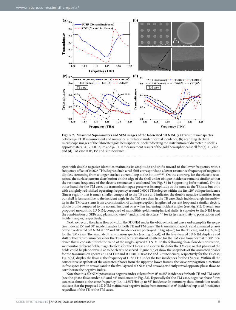
Figure 6. Phase flows within free space and five-layered 3D NIM under oblique incidence. Simulated transmission spectra of five-layered 3D NIMs under 0°, 15° and 30° incidences for (a) TE and (d) TM cases. The animated phases of magnetic fields under (b) 15° incidence at 1.134 THz and (c) 30° incidence at 1.081 THz and the animated phases of electric fields under (e) 15° incidence and (f) 30° incidence both at 1.185 THz are presented. In order to clarify the wave propagating direction, we monitor different fields, magnetic fields for TE case and electric fields for TM case so that the phase of fields could be plane-wave-like. The upper to lower frames in (b,c) to (e,f) are all with a constant step of phase change, i.e., 50-degree, and white arrows indicate the wave propagation direction in free space while red arrows in five-layered 3D NIM. The two are opposite and suggest the double negative identities of the 3D NIM.
www.nature.com/scientificreports/
6Scientific RepoRts | 7:45549 | DOI: 10.1038/srep45549
apex with double negative identities maintains its amplitude and shifts toward to the lower frequency with a frequency offset of 0.0028 THz/degree. Such a red shift corresponds to a lower resonance frequency of magnetic dipoles, stemming from a longer surface current loop at the bottom26,27. On the contrary, for the electric reso-nance, the surface current distribution on the edge of the shell under oblique incidence remains similar so that the resonant frequency of the electric resonance is unaltered (see Fig. S1 in Supporting Information). On the other hand, for the TM case, the transmission apex preserves its amplitude as the same as the TE case but only with a slightly red-shifted operating frequency around 0.0001 THz/degree within the first 20° oblique incidence (linear region) that is much smaller compared to the TE case and indicates the double negative identities from our shell is less sensitive to the incident angle in the TM case than in the TE case. Such incident-angle insensitiv-ity in the TM case stems from a combination of an imperceptibly lengthened current loop and a similar electric dipole profile compared to the normal incident ones when increasing incident angles (see Fig. S1). Overall, our proposed monolithic 3D NIM, composed of monolithic gold hemispherical shells, is superior to the NIM from the combination of SRRs and plasmonic wires1,2 and fishnet structure13,28 for its less sensitivity to polarization and incident angles, respectively.
Next, we record the phase flow of within the 3D NIM under the oblique incident cases and exemplify the nega-tive index at 15° and 30° incident angles for both TE and TM cases. The transmission spectra and animated phases of the five-layered 3D NIM at 15° and 30° incidences are portrayed in Fig. 6(a–c) for the TE case, and Fig. 6(d–f) for the TM cases. The simulated transmission spectra (see Fig. 6(a,d)) of the five-layered 3D NIM display a red shift of the transmission peaks for the TE case but stay almost unaltered for the TM case from normal to 30° inci-dence that is consistent with the trend of the single-layered 3D NIM. In the following phase flow demonstration, we monitor different fields, magnetic fields for the TE case and electric fields for the TM case so that phases of the fields could be plane-wave-like to be clearly observed. Figure 6(b,c) show the snapshots of the animated phases for the transmission apexes at 1.134 THz and at 1.081 THz at 15° and 30° incidences, respectively for the TE case; Fig. 6(e,f) display the flows at the frequency of 1.185 THz under the two incidences for the TM case. Within all the consecutive snapshots of the animated phases from the upper to lower frames, the wave propagation directions in free space (white arrows) and in the five-layered 3D NIM (red arrows) evidently reveal opposite phase flows to corroborate the negative index.
Note that this 3D NIM possesses a negative index at least from 0° to 85° incidences for both TE and TM cases (see the phase flows under 60° and 85° incidences in Fig. S2). Especially for the TM case, negative phase flows can exist almost at the same frequency (i.e., 1.185 THz) up to 85° incidence. In summary, these simulation results indicate that the proposed 3D NIM maintains a negative index from normal (i.e. 0° incidence) up to 85° incidence regardless of the TE or the TM cases.
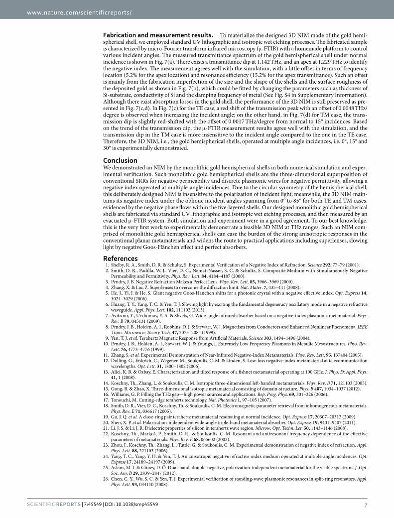
Figure 7. Measured S-parameters and SEM images of the fabricated 3D NIM. (a) Transmittance spectra between μ -FTIR measurement and numerical simulation under normal incidence, (b) scanning electron microscope images of the fabricated gold hemispherical shell indicating the distribution of diameter in shell is approximately 34.17 ± 0.52 μ m and μ -FTIR measurement results of the gold hemispherical shell for (c) TE case and (d) TM case at 0°, 15° and 30° incidence.
www.nature.com/scientificreports/
7Scientific RepoRts | 7:45549 | DOI: 10.1038/srep45549
Fabrication and measurement results. To materialize the designed 3D NIM made of the gold hemi-spherical shell, we employed standard UV lithographic and isotropic wet etching processes. The fabricated sample is characterized by micro-Fourier transform infrared microscopy (μ -FTIR) with a homemade platform to control various incident angles. The measured transmittance spectrum of the gold hemispherical shell under normal incidence is shown in Fig. 7(a). There exists a transmittance dip at 1.142 THz, and an apex at 1.229 THz to identify the negative index. The measurement agrees well with the simulation, with a little offset in terms of frequency location (5.2% for the apex location) and resonance efficiency (15.2% for the apex transmittance). Such an offset is mainly from the fabrication imperfection of the size and the shape of the shells and the surface roughness of the deposited gold as shown in Fig. 7(b), which could be fitted by changing the parameters such as thickness of Si-substrate, conductivity of Si and the damping frequency of metal (See Fig. S4 in Supplementary Information). Although there exist absorption losses in the gold shell, the performance of the 3D NIM is still preserved as pre-sented in Fig. 7(c,d). In Fig. 7(c) for the TE case, a red shift of the transmission peak with an offset of 0.0048 THz/degree is observed when increasing the incident angle; on the other hand, in Fig. 7(d) for TM case, the trans-mission dip is slightly red-shifted with the offset of 0.0017 THz/degree from normal to 15° incidences. Based on the trend of the transmission dip, the μ -FTIR measurement results agree well with the simulation, and the transmission dip in the TM case is more insensitive to the incident angle compared to the one in the TE case. Therefore, the 3D NIM, i.e., the gold hemispherical shells, operated at multiple angle incidences, i.e. 0°, 15° and 30° is experimentally demonstrated.
ConclusionWe demonstrated an NIM by the monolithic gold hemispherical shells in both numerical simulation and exper-imental verification. Such monolithic gold hemispherical shells are the three-dimensional superposition of conventional SRRs for negative permeability and discrete plasmonic wires for negative permittivity, allowing a negative index operated at multiple-angle incidences. Due to the circular symmetry of the hemispherical shell, this deliberately designed NIM is insensitive to the polarization of incident light; meanwhile, the 3D NIM main-tains its negative index under the oblique incident angles spanning from 0° to 85° for both TE and TM cases, evidenced by the negative phase flows within the five-layered shells. Our designed monolithic gold hemispherical shells are fabricated via standard UV lithographic and isotropic wet etching processes, and then measured by an evacuated μ -FTIR system. Both simulation and experiment were in a good agreement. To our best knowledge, this is the very first work to experimentally demonstrate a feasible 3D NIM at THz ranges. Such an NIM com-prised of monolithic gold hemispherical shells can ease the burden of the strong anisotropic responses in the conventional planar metamaterials and widens the route to practical applications including superlenses, slowing light by negative Goos-Hänchen effect and perfect absorbers.
References1. Shelby, R. A., Smith, D. R. & Schultz, S. Experimental Verification of a Negative Index of Refraction. Science 292, 77–79 (2001).2. Smith, D. R., Padilla, W. J., Vier, D. C., Nemat-Nasser, S. C. & Schultz, S. Composite Medium with Simultaneously Negative
Permeability and Permittivity. Phys. Rev. Lett. 84, 4184–4187 (2000).3. Pendry, J. B. Negative Refraction Makes a Perfect Lens. Phys. Rev. Lett. 85, 3966–3969 (2000).4. Zhang, X. & Liu, Z. Superlenses to overcome the diffraction limit. Nat. Mater. 7, 435–441 (2008).5. He, J., Yi, J. & He, S. Giant negative Goos-Hänchen shifts for a photonic crystal with a negative effective index. Opt. Express 14,
3024–3029 (2006).6. Huang, T. Y., Yang, T. C. & Yen, T. J. Slowing light by exciting the fundamental degeneracy oscillatory mode in a negative refractive
waveguide. Appl. Phys. Lett. 102, 111102 (2013).7. Avitzour, Y., Urzhumov, Y. A. & Shvets, G. Wide-angle infrared absorber based on a negative-index plasmonic metamaterial. Phys.
Rev. B 79, 045131 (2009).8. Pendry, J. B., Holden, A. J., Robbins, D. J. & Stewart, W. J. Magnetism from Conductors and Enhanced Nonlinear Phenomena. IEEE
Trans. Microwave Theory Tech. 47, 2075–2084 (1999).9. Yen, T. J. et al. Terahertz Magnetic Response from Artificial Materials. Science 303, 1494–1496 (2004).
10. Pendry, J. B., Holden, A. J., Stewart, W. J. & Youngs, I. Extremely Low Frequency Plasmons in Metallic Mesostructures. Phys. Rev. Lett. 76, 4773–4776 (1999).
11. Zhang, S. et al. Experimental Demonstration of Near-Infrared Negative-Index Metamaterials. Phys. Rev. Lett. 95, 137404 (2005).12. Dolling, G., Enkrich, C., Wegener, M., Soukoulis, C. M. & Linden, S. Low-loss negative-index metamaterial at telecommunication
wavelengths. Opt. Lett. 31, 1800–1802 (2006).13. Alici, K. B. & Ozbay, E. Characterization and tilted response of a fishnet metamaterial operating at 100 GHz. J. Phys. D: Appl. Phys.
41, 1 (2008).14. Koschny, Th., Zhang, L. & Soukoulis, C. M. Isotropic three-dimensional left-handed metamaterials. Phys. Rev. B 71, 121103 (2005).15. Gong, B. & Zhao, X. Three-dimensional isotropic metamaterial consisting of domain-structure. Phys. B 407, 1034–1037 (2012).16. Williams, G. P. Filling the THz gap—high power sources and applications. Rep. Prog. Phys. 69, 301–326 (2006).17. Tonouchi, M. Cutting-edge terahertz technology. Nat. Photonics 1, 97–105 (2007).18. Smith, D. R., Vier, D. C., Koschny, Th. & Soukoulis, C. M. Electromagnetic parameter retrieval from inhomogeneous metamaterials.
Phys. Rev. E 71, 036617 (2005).19. Gu, J. Q. et al. A close-ring pair terahertz metamaterial resonating at normal incidence. Opt. Express 17, 20307–20312 (2009).20. Shen, X. P. et al. Polarization-independent wide-angle triple-band metamaterial absorber. Opt. Express 19, 9401–9407 (2011).21. Li, J. S. & Li, J. R. Dielectric properties of silicon in terahertz wave region. Microw. Opt. Techn. Let. 50, 1143–1146 (2008).22. Koschny, Th., Markoš, P., Smith, D. R. & Soukoulis, C. M. Resonant and antiresonant frequency dependence of the effective
parameters of metamaterials. Phys. Rev. E 68, 065602 (2003).23. Zhou, J., Koschny, Th., Zhang, L., Tuttle, G. & Soukoulis, C. M. Experimental demonstration of negative index of refraction. Appl.
Phys. Lett. 88, 221103 (2006).24. Yang, T. C., Yang, Y. H. & Yen, T. J. An anisotropic negative refractive index medium operated at multiple-angle incidences. Opt.
Express 17, 24189–24197 (2009).25. Aslam, M. I. & Güney, D. Ö. Dual-band, double-negative, polarization-independent metamaterial for the visible spectrum. J. Opt.
Soc. Am. B 29, 2839–2847 (2012).26. Chen, C. Y., Wu, S. C. & Yen, T. J. Experimental verification of standing-wave plasmonic resonances in split-ring resonators. Appl.
Phys. Lett. 93, 034110 (2008).
www.nature.com/scientificreports/
8Scientific RepoRts | 7:45549 | DOI: 10.1038/srep45549
27. Chang, Y. T., Lai, Y. C., Li, C. T., Chen, C. K. & Yen, T. J. A multi-functional plasmonic biosensor. Opt. Express 18, 9561–9569 (2010).28. Sabah, C. & Roskos, H. G. Dual-band polarization-independent sub-terahertz fishnet metamaterial. Curr. Appl. Phys. 12, 443–450
(2012).
AcknowledgementsThe authors would like to gratefully acknowledge the financial support from the Ministry of Science and Technology (MOST 101-2628-E-007-016-MY3, 102-2221-E-007-113-MY4, 103-2633-M-007-001 106-2923-E-007-003 and 104-2218-E-007-020-MY3), and by the Ministry of Education (“Aim for the Top University Plan” for National Tsing Hua University under project number 105N519CE1).
Author ContributionsTa-Jen Yen conceived the project, Ting-Tso Yeh simulated, fabricated, and measured the samples and Ting-Tso Yeh analytically also calculated the retrieval data. Ta-Jen Yen, Ting-Tso Yeh and Tsung-Yu Huang co-wrote the paper. Takuo Tanaka contributed to the revision of the manuscript and supplementary information. All authors discussed the results and commented on the manuscript.
Additional InformationSupplementary information accompanies this paper at http://www.nature.com/srepCompeting Interests: The authors declare no competing financial interests.How to cite this article: Yeh, T.-T. et al. Demonstration of a Three-dimensional Negative Index Medium Operated at Multiple-angle Incidences by Monolithic Metallic Hemispherical Shells. Sci. Rep. 7, 45549; doi: 10.1038/srep45549 (2017).Publisher's note: Springer Nature remains neutral with regard to jurisdictional claims in published maps and institutional affiliations.
This work is licensed under a Creative Commons Attribution 4.0 International License. The images or other third party material in this article are included in the article’s Creative Commons license,
unless indicated otherwise in the credit line; if the material is not included under the Creative Commons license, users will need to obtain permission from the license holder to reproduce the material. To view a copy of this license, visit http://creativecommons.org/licenses/by/4.0/ © The Author(s) 2017
Supplementary Information
Demonstration of a Three-dimensional Negative Index Medium Operated at Multiple-angle Incidences by Monolithic Metallic Hemispherical Shells (Running title: A Negative Index Medium Operated under Oblique Incidence)
Ting-Tso Yeh1, Tsung-Yu Huang1 and Ta-Jen Yen1,2 1Department of Material Science and Engineering, National Tsing Hua University, Hsinchu, Taiwan, R.O.C. 2Department of Materials Science Center for Nanotechnology, Materials Science, and Microsystems, National
Tsing Hua University, Hsinchu, Taiwan, R.O.C.
Correspondence: *Prof. Ta-Jen Yen, Department of Materials Science and Engineering, National Tsing Hua
University101, Section 2, Kuang Fu Road, Hsinchu 30013, Taiwan, R.O.C.
Email: [email protected]
Keywords: multiple-angle incidences; negative index; terahertz; three-dimensional metamaterials
Supplementary Information
• Mechanisms of red-shifted resonant frequency at normal, 15°and 30°
incidences based on surface current distributions of the gold
hemispherical shell
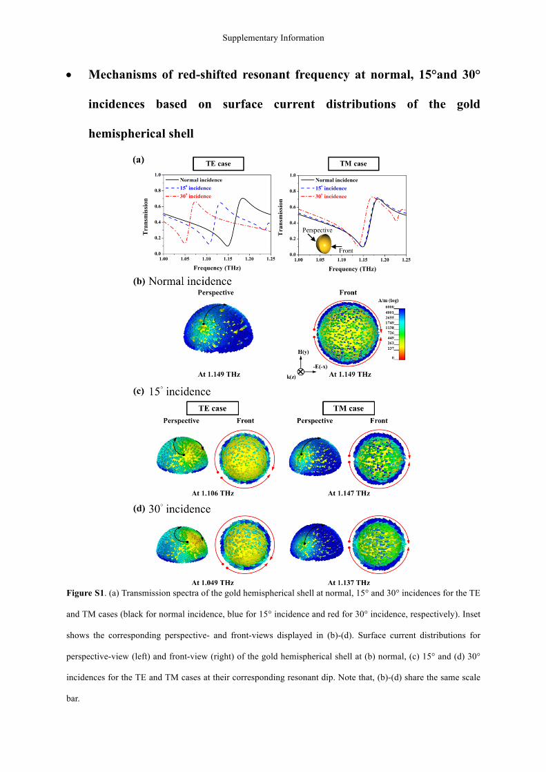
Figure S1. (a) Transmission spectra of the gold hemispherical shell at normal, 15° and 30° incidences for the TE
and TM cases (black for normal incidence, blue for 15° incidence and red for 30° incidence, respectively). Inset
shows the corresponding perspective- and front-views displayed in (b)-(d). Surface current distributions for
perspective-view (left) and front-view (right) of the gold hemispherical shell at (b) normal, (c) 15° and (d) 30°
incidences for the TE and TM cases at their corresponding resonant dip. Note that, (b)-(d) share the same scale
bar.
Supplementary Information
To explain mechanisms of the red-shifted resonant frequency for both TE and TM
waves when increasing incident angles, we monitor surface current distributions of the shell
at normal, 15° and 30° incidences at the corresponding resonant dips (see Figure S1(a)) as
shown in Figure S1(b)-(d). As plotted in Figure S1(b), for normal incidence, the currents at
the bottom center denoted by a black arrow majorly contribute to the magnetic dipoles along
y direction. Furthermore, induced surface currents along the edge of the shell denoted by red
arrows lead to electric dipoles as mentioned in the main text. Therefore, our proposed shell
could possess double negative identities at 1.149 THz from the combination of the induced
magnetic and electric dipoles. Now, we would like to discuss cases for oblique incidences.
First of all, for the TE case (left column from Figure S1(c)-(d)), when the incident angle tilts
from 0° to 15°, the surface current distributions become asymmetrically distorted and form a
greater length of the loop of the induced currents denoted by a black arrow in Figure S1(c)
than the case under normal incidence so that there still exist magnetic dipoles, yet resonating
at a lower frequency. Even the induced currents at the edge become asymmetry compared to
the normal incident case, the net electric dipoles are still along x-direction, resulting in a
small shift of the plasma frequency of Drude-model-like resonance and possessing
insignificant influences on the regime of the negative index. Combining the frequency shifts
of the magnetic and electric dipoles, the region of the negative index shifts to a lower
frequency, i.e., 1.106 THz when the incident angle is up to 15°. To further increase the
incident angle to 30°, a much larger loop denoted by black arrows as illustrated in Figure S1d
and similar electric dipoles give rise to red-shifted negative index accompanied with a red-
shifted resonant dip at 1.049 THz. As for the TM case (right column in Figure S1(c)-(d)), the
surface current distributions at 15° and 30° incidences are both similar to the distribution in
the normal incidence case but with a little longer path at 15° and 30° incidences as suggested
by the closer distance between the node and the edge at 30° incidence. Consequently, the
Supplementary Information
magnetic resonance barely red-shifts to 1.147 THz at 15° incidence and to 1.137 THz at 30°
incidence compared to 1.149 THz under normal incidence. On the other hand, the current
distributions that form electric dipoles at both 15° and 30° incidences are the same as the
distributions under normal incidence; thus, the electric resonance fixed at the same frequency
under the oblique incidences. Therefore, the slightly red-shifted resonant dip for TM case
under oblique incidences is caused by imperceptibly longer paths of the induced surface
currents, thus resulting in a magnetic dipole resonance at a lower frequency and similar
current profiles on the edge of the shell, leading to an electric dipole similar to the normal
incident one when increasing the incident angle.
Supplementary Information
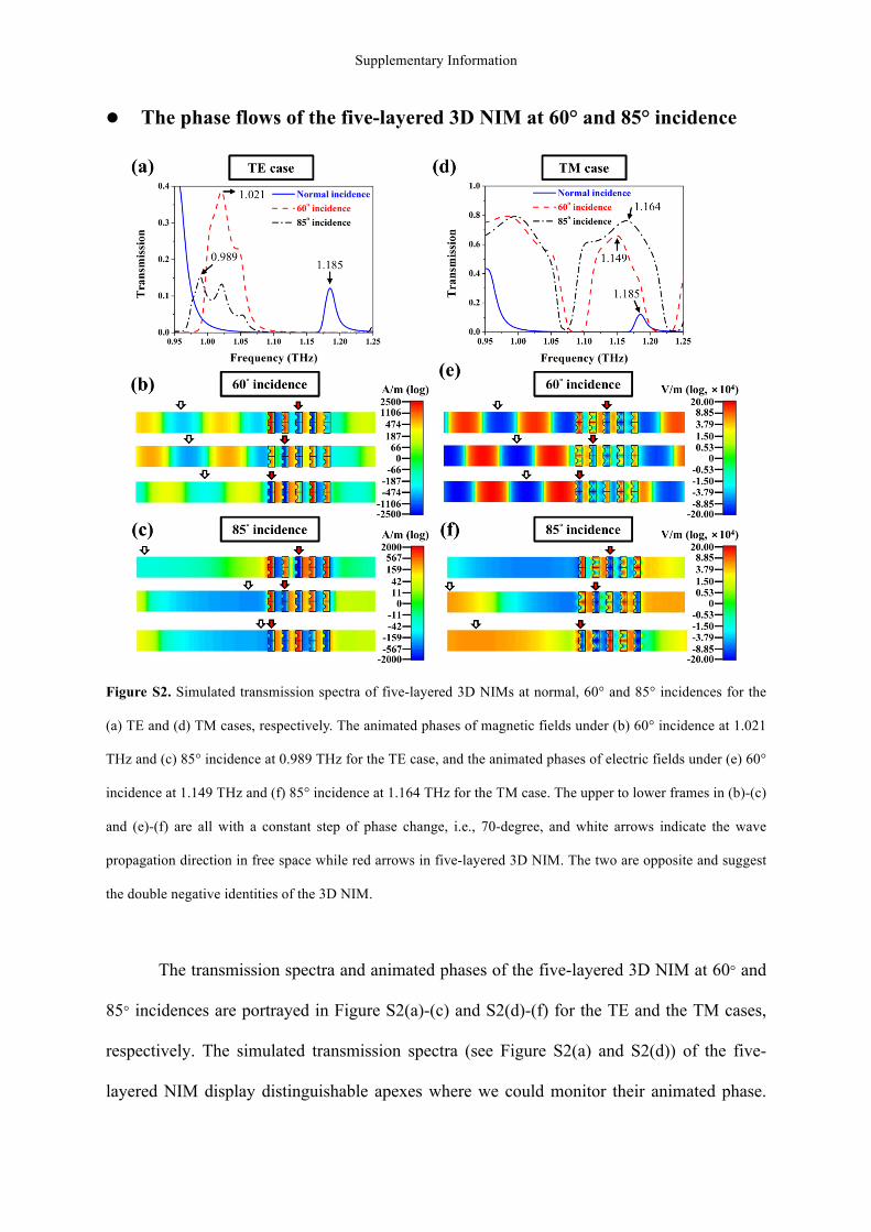
l The phase flows of the five-layered 3D NIM at 60° and 85° incidence
Figure S2. Simulated transmission spectra of five-layered 3D NIMs at normal, 60° and 85° incidences for the
(a) TE and (d) TM cases, respectively. The animated phases of magnetic fields under (b) 60° incidence at 1.021
THz and (c) 85° incidence at 0.989 THz for the TE case, and the animated phases of electric fields under (e) 60°
incidence at 1.149 THz and (f) 85° incidence at 1.164 THz for the TM case. The upper to lower frames in (b)-(c)
and (e)-(f) are all with a constant step of phase change, i.e., 70-degree, and white arrows indicate the wave
propagation direction in free space while red arrows in five-layered 3D NIM. The two are opposite and suggest
the double negative identities of the 3D NIM.
The transmission spectra and animated phases of the five-layered 3D NIM at 60° and
85° incidences are portrayed in Figure S2(a)-(c) and S2(d)-(f) for the TE and the TM cases,
respectively. The simulated transmission spectra (see Figure S2(a) and S2(d)) of the five-
layered NIM display distinguishable apexes where we could monitor their animated phase.
Supplementary Information
Figure 6(b) and 6(c) show the snapshots of the animated phases at the transmission apexes of
1.021 THz and 0.989 THz under 60° and 85° incidences, respectively for the TE case; Figure
6(e) and 6(f) display the flows at the frequencies of 1.149 THz under 60° incidence and of
1.164 THz under 85° incidence, respectively for the TM case. Within all the snapshots of the
animated phases, the wave propagation direction in free space is denoted by white arrows; in
contrast, the wave propagation direction within the five-layered 3D NIM is denoted by red
arrows and from the upper to lower frames, the white arrows go from left to right when the
red arrows go from right to left, an indication of opposite phase flows and negative index as
well. Herein, our proposed 3D NIM, the gold hemispherical shell, theoretically preserved
double negative identities up to 85°.
Supplementary Information
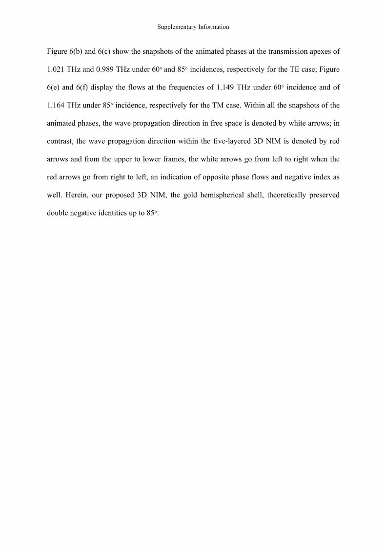
l Performance of our metallic shells incident from two opposite sides
Once the sample is flipped, we could still obtain identical transmission and similar reflection
compared to the one with the light shedding from the front side under normal and oblique
incidences as shown in Fig. S3.
Figure S3. (a) Simulated transmittance and reflectance spectra of the gold shells under normal incidence and (b) their retrieval results from front-side and back-side. Transmittance and Reflectance spectra under (c) 15° incidence, (d) 30° incidence in the TE case and (d) 15° incidence and (e) 30° incidence in the TM case from front-side and back-side.
Supplementary Information
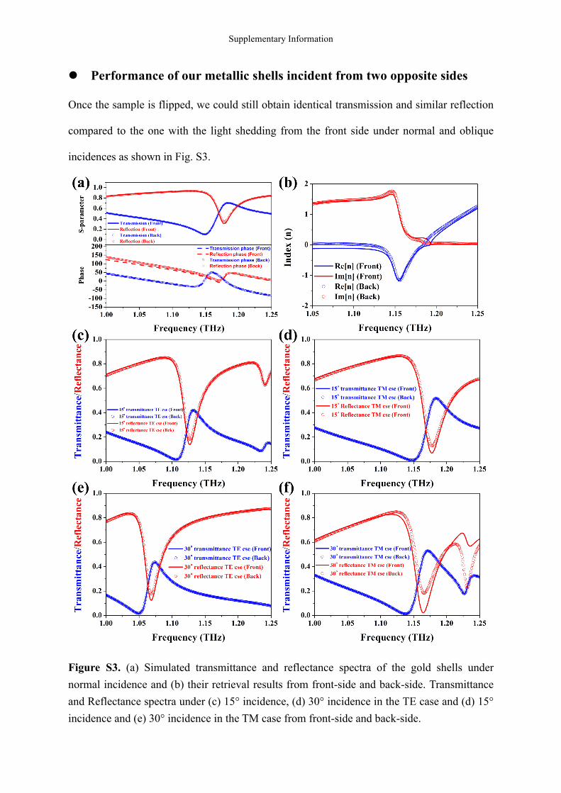
l Revised parameters in simulation for a better fit to the experimental
results
Our experimental demonstration agrees well the numerical simulation with only a little offset
(i.e., 5.2% for the frequency offset and 15.2% for the transmission offset). The offset stems
from the deviated thickness of Si substrate caused by Si back etching, and the roughness of
gold that is impractical to estimate before the experiments. We can modify our simulation
parameters to further approach the experimental results by changing the thickness of Si
substrates, damping frequency of metal and the conductivity of the Si substrate as shown in
Fig. S4.
Figure S4. (a) Modified and original parameters of 3D metamaterials including the thickness and conductivity of the silicon substrate and the damping frequency of gold. Note that the modified damping frequency of gold is set 450-times greater than the value provided in the [R3]. (b) Comparison between simulated and measured transmittance spectra based on the modified parameters.
Supplementary Information
l Misalignment when piling up to five-layered 3D metamaterials
Limited by our measurement facilities, we can only measure a single-layered sample under 0°
(i.e., normal), 15° and 30° incidences for both TE and TM waves, and then compared them to
the simulated ones, as shown in Fig. 7 in the main text. Again, the results of simulation and
measurement agree one another well, demonstrating negative refraction at multiple-angle
incidences by our designed monolithic metallic hemispherical shells. Besides, single-layered
metallic hemispherical shells suffice to be regarded as a negative refractive index medium
(NRIM). The reason that we employed a five-layered configuration instead of a single-
layered configuration is to visualize the opposite phase flows in the structures and in free
space to indicate negative refraction. Therefore, the measurement of a five-layered sample is
not a must, because one cannot directly observe the phase flow in structures.
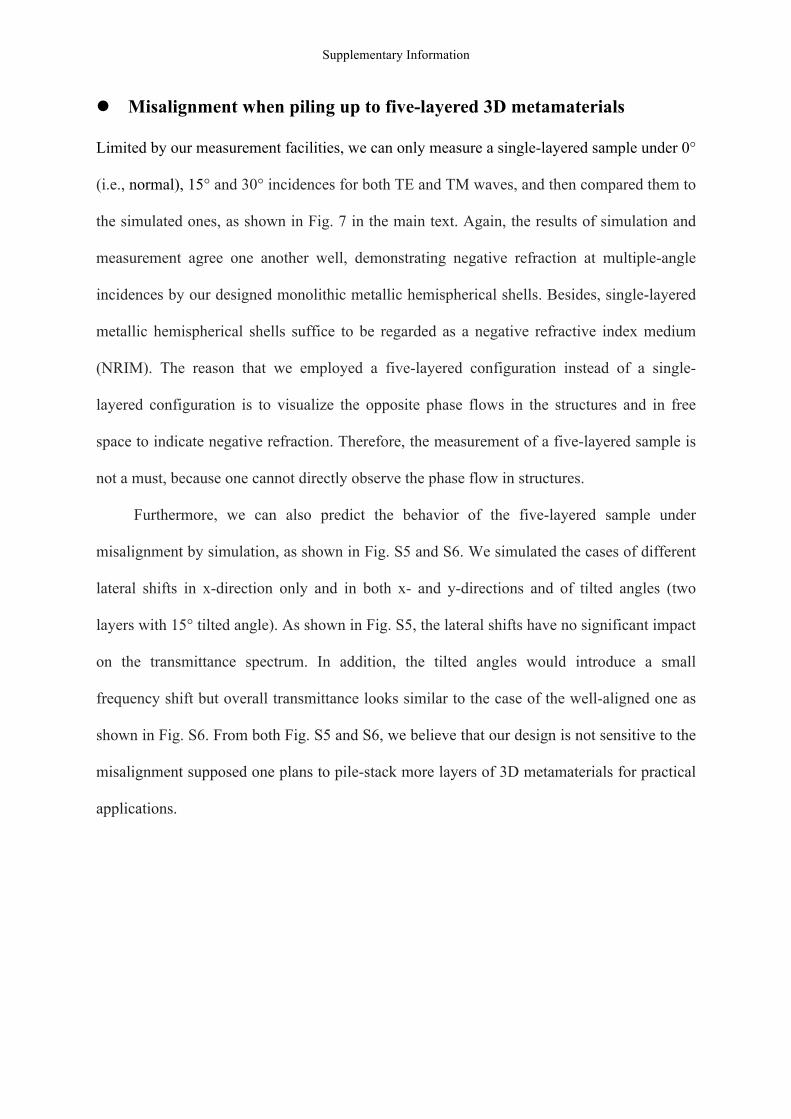
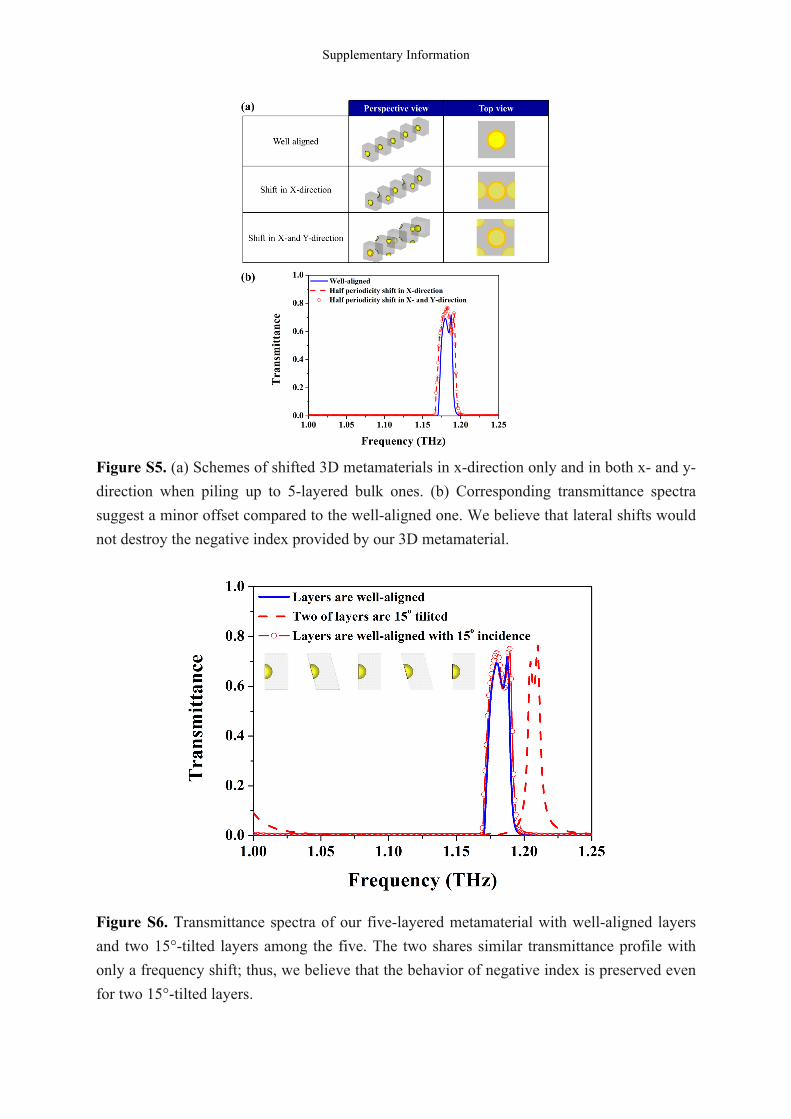
Furthermore, we can also predict the behavior of the five-layered sample under
misalignment by simulation, as shown in Fig. S5 and S6. We simulated the cases of different
lateral shifts in x-direction only and in both x- and y-directions and of tilted angles (two
layers with 15° tilted angle). As shown in Fig. S5, the lateral shifts have no significant impact
on the transmittance spectrum. In addition, the tilted angles would introduce a small
frequency shift but overall transmittance looks similar to the case of the well-aligned one as
shown in Fig. S6. From both Fig. S5 and S6, we believe that our design is not sensitive to the
misalignment supposed one plans to pile-stack more layers of 3D metamaterials for practical
applications.
Supplementary Information
Figure S5. (a) Schemes of shifted 3D metamaterials in x-direction only and in both x- and y-direction when piling up to 5-layered bulk ones. (b) Corresponding transmittance spectra suggest a minor offset compared to the well-aligned one. We believe that lateral shifts would not destroy the negative index provided by our 3D metamaterial.
Figure S6. Transmittance spectra of our five-layered metamaterial with well-aligned layers and two 15°-tilted layers among the five. The two shares similar transmittance profile with only a frequency shift; thus, we believe that the behavior of negative index is preserved even for two 15°-tilted layers.