Embed Size (px)
Citation preview
Demo: Automated Valet Parking and Charging
Stephan Rottmann, Julian Timpner, and Lars WolfInstitute of Operating Systems and Computer Networks
Technische Universitat BraunschweigBraunschweig, Germany
Email: (rottmann|timpner|wolf)@ibr.cs.tu-bs.de
Abstract—A model electric vehicle performing automatedvalet parking and charging is demonstrated. The vehi-cle’s missions are transmitted using WLAN based vehicle-to-infrastructure communications by a server back-end which hasbeen developed in the EU FP7 project V-Charge.
I. THE V-CHARGE PROJECT
The European Union FP7 project V-Charge1 (AutomatedValet Parking and Charging for e-Mobility) offers a sophisti-cated combination of public transport and individual electricalmobility by introducing automated valet parking based onclose-to-market sensors and coordinated charging strategies.This system allows drivers to drop off (and to pick up) theirelectric vehicle in front of a public transport hub (e.g., anairport) without taking care of parking or recharging. Thevehicle executes these tasks autonomously. This implies threemajor fields of research: (i) vehicle functionality, e.g., on-boardlocalization and planning, (ii) logistics, scheduling of parkingand charging resources, and (iii) infrastructure, a secure andreliable framework to store and share a database of parkingarea information. [1]
In this demo, we present a research and developmentplatform showcasing the abovementioned aspects of the actualV-Charge project while also providing an educational tool forstudents to learn about automated driving, localization, andvehicular communications. Our platform consists of a vehiclesystem, that is based on a 6-wheel-drive chassis equippedwith a computing and sensor platform, as well as a serversystem, providing the vehicle with mission goals and a remotemonitoring station. Using the server application, a destinationsuch as a parking spot or a charging station can be set, whichthe vehicle will then automatically navigate and maneuver to.In case of a charging task, the vehicle will also be charged au-tomatically. Compared to the actual V-Charge vehicles, whichare based on the VW Golf platform, our miniature vehiclesallow cheap, easy and rapid development and prototyping,which is especially useful as an educational tool.
II. DEMONSTRATION PLATFORM
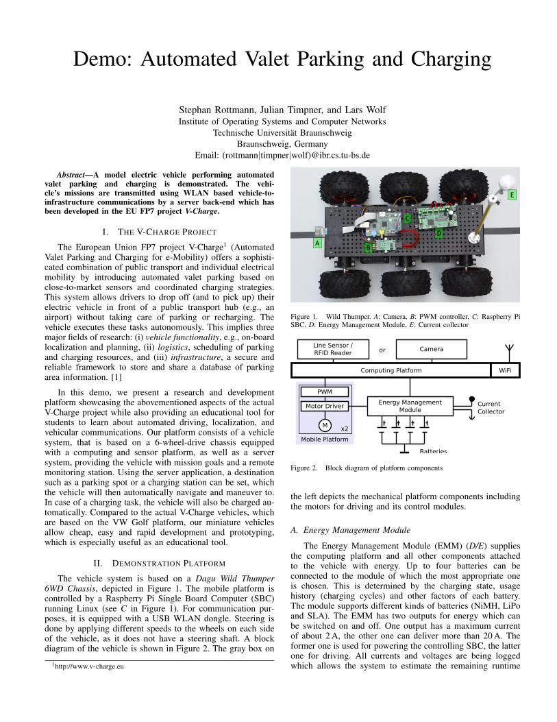
The vehicle system is based on a Dagu Wild Thumper6WD Chassis, depicted in Figure 1. The mobile platform iscontrolled by a Raspberry Pi Single Board Computer (SBC)running Linux (see C in Figure 1). For communication pur-poses, it is equipped with a USB WLAN dongle. Steering isdone by applying different speeds to the wheels on each sideof the vehicle, as it does not have a steering shaft. A blockdiagram of the vehicle is shown in Figure 2. The gray box on
1http://www.v-charge.eu
A
C
B
D
E
Figure 1. Wild Thumper. A: Camera, B: PWM controller, C: Raspberry PiSBC, D: Energy Management Module, E: Current collector
Computing Platform
M
Motor DriverEnergy Management
ModuleCurrentCollector
Batteries
WiFi
PWM
Mobile Platform
orLine Sensor /RFID Reader
Camera
x2
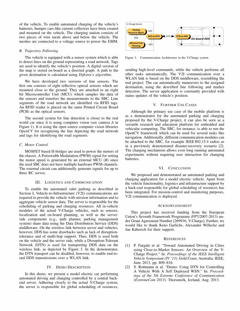
Figure 2. Block diagram of platform components
the left depicts the mechanical platform components includingthe motors for driving and its control modules.
A. Energy Management Module
The Energy Management Module (EMM) (D/E) suppliesthe computing platform and all other components attachedto the vehicle with energy. Up to four batteries can beconnected to the module of which the most appropriate oneis chosen. This is determined by the charging state, usagehistory (charging cycles) and other factors of each battery.The module supports different kinds of batteries (NiMH, LiPoand SLA). The EMM has two outputs for energy which canbe switched on and off. One output has a maximum currentof about 2 A, the other one can deliver more than 20 A. Theformer one is used for powering the controlling SBC, the latterone for driving. All currents and voltages are being loggedwhich allows the system to estimate the remaining runtime
of the vehicle. To enable automated charging of the vehicle’sbatteries, bumper cars-like current collectors have been createdand mounted on the vehicle. The charging station consists oftwo pieces of wire mesh above and below the vehicle. Themeshes are connected to a voltage source to power the EMM.
B. Trajectory Following
The vehicle is equipped with a sensor system which is ableto detect lines on the ground representing a road network. Tagsare used to identify the vehicle’s position. A digital version ofthe map is stored on-board as a directed graph. A path to thegiven destination is calculated using Dijkstra’s algorithm.
We have developed two versions of line sensors. Thefirst one consists of eight reflective optical sensors which aremounted close to the ground. They are attached to an eightbit Microcontroller Unit (MCU) which samples the data ofthe sensors and transfers the measurements to the SBC. Linesegments of the road network are identified via RFID tags.An RFID reader is placed on the same Printed Circuit Board(PCB) as the optical sensors.
The second system for line detection is closer to the realworld car since it is using computer vision (see camera A inFigure 1). It is using the open source computer vision librariesOpenCV for recognizing the line depicting the road networkand tags for identifying the road segments.
C. Motor Control
MOSFET based H-bridges are used to power the motors ofthe chassis. A Pulsewidth Modulation (PWM) signal for settingthe motor speed is generated by an external MCU (B) sincethe used SBC does not have multiple hardware PWM channels.The external circuit can additionally generate signals for up tothree RC servos.
III. LOGISTICS AND COMMUNICATION
To enable the automated valet parking as described inSection I, Vehicle-to-Infrastructure (V2I) communications arerequired to provide the vehicle with mission information and toaggregate vehicle sensor data. The server is responsible for thescheduling of parking and charging resources. All in-vehiclemodules of the actual V-Charge vehicles, such as sensors,localization and on-board planning, as well as the server-side components (e.g., path planner, parking managementsystem) share data using the Data Distribution Service (DDS)middleware. On the wireless link between server and vehicles,however, DDS has some drawbacks such as lack of disruption-tolerance and of multi-hop support. Thus, DDS is used bothon the vehicle and the server side, while a Disruption-TolerantNetwork (DTN) is used for transporting DDS data on thewireless link, as depicted by Figure 3. In the demonstrator,the DTN transport can be disabled, however, to enable end-to-end DDS transmissions over a WLAN link.
IV. DEMO DESCRIPTION
In this demo, we present a model electric car performingautomated driving and charging controlled by a central back-end server. Adhering closely to the actual V-Charge system,the server is responsible for global scheduling of resources,
V-Charge Server
Parking Resource Mgmt
Mission/Task Planning
DDSDTNDDS-to-DTN
DDS
DDS
On-board DDSDTN-to-DDS
Figure 3. Communication Architecture in the V-Charge system
sending high-level commands, while the vehicle performs allother tasks automatically. The V2I communication over aWLAN link is based on the DDS middleware, resembling thereal project. The car automatically maneuvers to the assigneddestination, using the described line following and markerdetection. The server application is constantly provided withstatus updates of the vehicle’s position.
V. FURTHER USE CASES
Although the primary use case of the mobile platform isas a demonstrator for the automated parking and chargingproposed by the V-Charge project, it can also be seen as aversatile research and education platform for embedded andvehicular computing. The SBC, for instance, is able to run theOpenCV framework which can be used for several tasks likenavigation. Additionally, different communication modules canbe attached to the SBC, for example IEEE 802.15.4 radios asin a previously demonstrated disaster-recovery scenario [2].The charging mechanism allows even long running automatedexperiments without requiring user interaction for changingbatteries.
VI. CONCLUSION
We proposed and demonstrated an automated parking andcharging application for a model electric vehicle. Apart fromthe vehicle functionality, logistics and infrastructure support bya back-end responsible for global scheduling of resources hasbeen integrated. For mission-control and monitoring purposes,V2I communication is deployed.
ACKNOWLEDGMENT
This project has received funding from the EuropeanUnion’s Seventh Framework Programme (FP7/2007-2013) un-der Grant Agreement Number [269916, V-Charge]. Further, wewould like to thank Keno Garlichs, Alexander Willecke andJan Kaberich for their support.
REFERENCES
[1] P. Furgale et al. “Toward Automated Driving in Citiesusing Close-to-Market Sensors: An Overview of the V-Charge Project.” In: Proceedings of the IEEE IntelligentVehicle Symposium (IV ’13). Gold Coast, Australia: IEEE,June 2013, pp. 809–816.
[2] S. Rottmann et al. “Demo: Using DTN for ControllingA Vehicle With A Self Deployed WSN.” In: Proceed-ings of the 5th Extreme Conference of Communication(ExtremeCom 2013). Thorsmork, Iceland, Aug. 2013.