Embed Size (px)
Citation preview
Received June 3, 2019, accepted June 23, 2019, date of publication June 28, 2019, date of current version July 18, 2019.
Digital Object Identifier 10.1109/ACCESS.2019.2925659
Demand Response From the Control ofAggregated Inverter Air ConditionersYANBO CHE 1, (Member, IEEE), JIANXIONG YANG1, YUE ZHOU 2, (Member, IEEE),YUANCHENG ZHAO 1, WEI HE3, AND JIANZHONG WU 2, (Member, IEEE)1Key Laboratory of Smart Grid of Ministry of Education, Tianjin University, Tianjin 300072, China2School of Engineering, Cardiff University, Cardiff CF24 3AA, U.K.3State Grid Jiangxi Electric Power Research Institute, Nanchang 330096, China
Corresponding author: Yue Zhou ([email protected])
This work was supported in part by the State Grid Corporation of China (SGCC) Program, Research on Extensive Application and BenefitEvaluation of Typical Power Substitution Technology Considering Power Quality Influence, under Grant 52182018000H, and in part bythe Research Councils UK’s (RCUK’s) Energy Programme ‘Joint UK-India Clean Energy Centre (JUICE)’ under Grant EP/P003605/1.
ABSTRACT Inverter air conditioners (ACs) account for a large proportion of air conditioning loads inmany countries and, thus, contribute significantly to the peak loads in these areas, especially in summer.On the other hand, as an important category of thermostatically controlled load with thermal energystorage capability, inverter ACs also have the potential to provide considerable flexibility for electric powersystems that are faced with increasing challenges posed by high penetration of renewable power generation.This paper focuses on the demand response from the control of the aggregated inverter ACs for loadreduction. A virtual energy storage system (VESS) model that encapsulates the room with an inverter ACwas established based on the electric model of an inverter AC and the thermodynamic model of a room.Based on the VESS model, a virtual state of charge (VSOC) priority-based load reduction control methodwith temperature holding and linear recovery strategies was proposed. The VSOC priority based controlwas designed to decrease the negative impact of load reduction on customers’ thermal comfort from theperspective of the whole AC population. The temperature holding strategywas designed to reduce the electricpower of an AC while ensuring that the indoor temperature is always below the allowable limit. The linearrecover strategy was proposed to reduce the load rebound after load reduction. Four cases were studiedregarding the operation and load reduction of the 100 inverter ACs, and the simulation results verified themodels established and the effectiveness and advantages of the proposed load reduction control method.
INDEX TERMS Inverter air conditioner, demand response, load reduction, virtual energy storage system.
I. INTRODUCTIONWith the global consensus on preventing global warmingand boosting sustainable development, there is a rapidlyincreasing penetration of renewable power generation in elec-tric power systems. The intermittency and randomness ofrenewable energy, such as wind and solar energy, make iteven more difficult and costly for power systems to maintainthe balance between supply and demand. Furthermore, theassociated decreasing share of conventional generators, suchas thermal and hydro generating units, reduces the flexibilityat the supply side of power systems, making the situation evenmore critical.
Against this background, to utilize the flexibility atthe demand side of power systems becomes increasingly
The associate editor coordinating the review of this manuscript andapproving it for publication was Shantha Jayasinghe.
important, and there have been a huge number of researchactivities and industrial practices on demand responseacross the world [1]. Within the wide range of flexibleloads, thermostatically controlled loads (TCLs) are importantflexible resources due to their large electric power consump-tion and thermal energy storage capability. Within certainranges, the power consumption of TCLs can be shifted,reduced or reshaped without compromising customers’ ther-mal comfort. Therefore, there have been abundant studiesmade on utilizing TCLs to provide multiple types of demandresponse services, including load following [2], frequencyresponse [3], operating reserves [4], renewable generationfollowing [5], voltage stability improvement [6], etc.
Air conditioning loads are one of the major componentsof TCLs, which account for a large proportion of total andpeak loads in many areas especially in summer, such asthe south of China, California in the U.S., etc. As a result,
VOLUME 7, 2019 This work is licensed under a Creative Commons Attribution 3.0 License. For more information, see http://creativecommons.org/licenses/by/3.0/ 88163
Y. Che et al.: Demand Response From the Control of Aggregated Inverter ACs
extensive studies have been conducted regarding the demandresponse from both residential (such as those in [7]–[9]) andcommercial (as reviewed in [10]) air conditioning loads.
Most existing studies regarding the demand response fromair conditioners (ACs) focus on single speed ACs. However,in recent years, the number of inverter ACs keeps growing,accounting for a significant share of total ACs installed inmany areas and countries. For example, in the residentialsector of China, the percentage of inverter ACs in total num-ber of ACs has reached about 40% [11]. This percentage iseven higher in developed countries such as Japan, the U.S.and some European countries [12]. Compared to single speedACs, the compressor of an inverter AC is able to operate atvariable speeds, and thus inverter ACs have some advantagesincluding 1) higher comfort level because the indoor temper-ature is maintained within a narrow band around the set point,2) lower power consumption when thermostatically operatingaround the set point [13], and 3) better performance duringstartup, grid voltage variation and locked-rotor periods [13].
In this context, some preliminary research has beenconducted regarding the demand response from inverter ACs,which could be further classified into three categories. Thefirst category of studies are to explore the load reductionfrom inverter ACs. Ninagawa et al established neural net-work models based on practical operational data of inverterACs for simulating their load reduction response [14]. Thepractical communication environment was also emulated.Yang et al. [15] and Huang et al. [16] both focused on loadreduction strategies of aggregated ACs. In [16], thermal com-fort of customers was considered through a model embeddedwith predicted mean vote (PMV) and predicted percentageof dissatisfied (PPD). In [15], the maximum duration of loadreduction was considered. Considering the load reductionstrategy proposed in [15], power system network planningproblems were addressed in [17] and [18].
The second category of studies were made to controlinverter ACs to arbitrage in electricity markets. Song et almodeled inverter ACs as a thermal battery to be compatiblewith power system dispatch models, and a hierarchical con-trol framework was proposed to handle the heterogeneityof ACs, protect customers’ privacy and reduce the com-putational burden [19]. Hu et al established models forinverter ACs and room thermal dynamics, and proposedtemperature set point and frequency control methods forarbitraging in day-ahead and real-time electricity marketsrespectively [20], [21].
Furthermore, the third category of studies tried to controlinverter ACs to provide ancillary services for power systems.Kim et al established a dynamic model of a variable speedheat pump (VSHP) responding to the frequency regulationsignals, and small signal analysis was conducted to verify thatdirect load control could be generally applied to VSHPs [22].Kim et al further conducted experimental studies to explorethis research topic [23]. Hui et al proposed centralized anddecentralized control methods for inverter ACs to provideprimary frequency control services, with the signal delays and
detection errors analyzed [24]. Viriyautsahakul et al proposedto control inverter ACs to provide reactive power supportfor power systems [25]. Yao et al proposed market basedautonomous control for inverter ACs to provide ancillaryservices, such as frequency regulation and microgrid tie-line power smoothing [26]. The proposed control method isof good generalizability and protects the customers’ privacywell. Customers’ comfort is also able to be guaranteed fairly.Wang et al proposed a distributed consensus control methodfor controlling inverter ACs for renewable energy integra-tion, where the impact of communication failure could besignificantly reduced [27]. Cheng et al used inverter ACsto establish virtual synchronous generators to improve theinertia of power systems [28].
The work of this paper lies in the first category of studiesas described above, focusing on the load reduction from thecontrol of aggregated inverter ACs. However, compared tothe existing studies, such as [14]–[18], this paper has thefollowing contributions. Similar to that in [19], this papermodels the space with inverter ACs as virtual energy storagesystems (VESSs), but based on this model, this paper furtherproposes to control the ACs according to the descendingorder of virtual state of charge (VSOC) of VESSs. Moreover,an innovative ‘temperature holding’ strategy is proposed toconduct the load reduction for each inverter AC to guaranteethat the indoor temperature will not deviate beyond the pre-agreed upper limit. Furthermore, this paper proposes a linearrecovery strategy to reduce the load rebound after load reduc-tion, which has not been considered in the existing studiesregarding load reduction from inverter ACs. Besides, thispaper pays special attention to the load reduction for the peakcaused by the turning ON of large numbers of inverter ACswithin a short period of time.
The paper is organized as follows. Section II presents themodels involved in this work, including the electric modelof an inverter AC, the thermodynamic model of the room,and the VESS model that encapsulates the room with aninverter AC. Section III presents the VSOC priority basedload reduction control method with temperature holdingand linear recovery strategies. Section IV presents the casestudies. Finally, Section V concludes the paper.
II. MODELLING METHODOLOGYIn this section, the models involved in this paper arepresented, including the electric model of an inverter AC,the thermodynamic model of the room, and the VESS modelthat encapsulates the room with an inverter AC.
A. THE ELECTRIC MODEL OF AN INVERTER ACFor a conventional single speed AC, hysteresis control withtwo thresholds is adopted to control the ON/OFF status ofthe compressor to maintain the indoor temperature withinthe thresholds. The compressor periodically turns ON/OFFwhen the indoor temperature hits the upper/lower temperaturethresholds.
88164 VOLUME 7, 2019
Y. Che et al.: Demand Response From the Control of Aggregated Inverter ACs
FIGURE 1. The relationship between the operating frequency and thedifference between the indoor temperature and the set point for aninverter AC [29].
By contrast, for an inverter AC, the operating frequencyof its compressor can be adjusted continuously, based onthe difference between the indoor temperature and the tem-perature set point. Therefore, when the indoor temperatureis far from the set point, the inverter AC will operate athigh frequency to cool the space quickly. When the indoortemperature is close to the set point, the inverter AC willoperate at low frequency to maintain the indoor temperatureclosely around the set point. In this way, inverter ACs canprovide higher level of thermal comfort and consume lowerlevel of electricity during the temperature maintaining stagecompared with single speed ACs [13].
For an inverter AC which is turned ON, the relationshipbetween the operating frequency and the difference betweenthe indoor temperature and the set point is illustratedin Fig. 1 [29].
The relationship shown in Fig. 1 can be expressed as
f =
fmin 1T < ufmax − fmin
u− v· 1T +
(u− 2v)fmax − vfmin
u− vfmax 1T > v
(1)
where f (Hz) represents the operating frequency of theinverter AC; fmin(Hz) and fmax(Hz) are the minimum andmaximum operating frequency of the inverter AC; 1T (◦C)is the difference between the indoor temperature and theset point; u(◦C) and v(◦C) are the knee points as illustratedin Fig. 1.
The cooling and electric power of the inverter AC canbe simplified as linear functions of the operating frequency,which are expressed as [19]
Q = a · f + b, (2)
P = c · f + d, (3)
where Q(kW) and P(kW) represent the cooling and electricpower of the inverter AC respectively. a(kW/Hz), b(kW),c(kW/Hz) and d(kW) are constant coefficients.By taking (2) divided by (3), the coefficient of performance
(COP) of the inverter AC is expressed as
COP =a · f + bc · f + d
. (4)
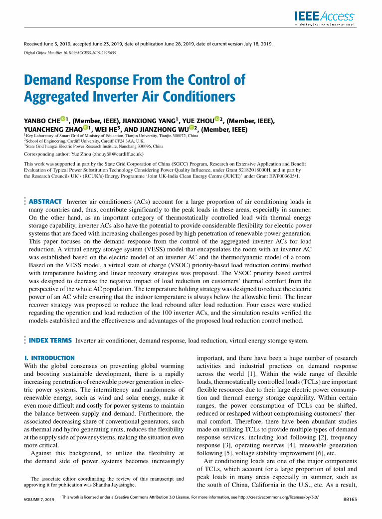
FIGURE 2. The model of the room with an inverter AC.
From (4), it is seen that the COP of an inverter AC is nota constant but varies with its operating frequency, which isdifferent from that of a single speed AC.
B. THERMODYNAMIC MODEL OF A ROOMThe first order equivalent thermal parameters (ETP)model [7] is adopted in this paper to simulate the thermody-namics of the space installed with inverter ACs. The model isexpressed as
C ·dTindt=Tout − Tin
R− Q (5)
where Tin(◦C) and Tout (◦C) represent the indoor and outdoortemperature; t is the variable representing the time;R(◦C/kW)and C(kWh/◦C) are the equivalent thermal resistance andthermal capacity respectively.
The differential equation (5) is discretized as the differenceequation as follows:
Tin(t+1)=Tout (t)−QR−[Tout (t)−Tin(t)−QR] · e−1t/(RC)
(6)
where 1t(h) is the length of a time step.
C. VESS MODEL ENCAPSULATING THE ROOM WITH ANINVERTER ACBased on the electric model and thermodynamic model pre-sented in the previous sub-sections (Sections II-A and II-B),the room with an inverter AC can be described by combining(1)-(6), which is illustrated in Fig. 2.
In order to conduct load reduction with minimum impacton customers’ thermal comfort, which will be detailed inSection III, the rooms with inverter ACs are modeled asVESSs. First of all, analogous to the SOC of batteries,the VSOC of the VESS is defined as
VSOC =Tmaxin − Tin
Tmaxin − T setpointin
(7)
where Tmaxin (◦C) is the pre-agreed maximum indoor
temperature during load reduction. Equation (7) is able to
VOLUME 7, 2019 88165
Y. Che et al.: Demand Response From the Control of Aggregated Inverter ACs
indicate the cooling energy stored in the room. When theindoor temperature Tin equals to the set point T setpointin ,the VSOC equals to 1 according (7), indicating that theroom stores maximum level of cooling energy consideringthat normally the indoor temperature will not be lower thanthe set point. When the Tin equals to the maximum indoortemperature Tmax
in , the VSOC equals to 0, indicating thatthe cooling energy stored reaches the lowest allowed level.Therefore, normally the value of VSOC will range within[0, 1]. When Tin exceeds Tmax
in , the VSOC will be negativevalues, indicating that the VESS has been over-discharged,i.e. the customers’ thermal comfort has been violated.
The charging/discharging of the VESS depends onrelationship between the cooling power of the inverter AC andthe stand-by heat gain of the room due to the higher outdoortemperature, as described in the right side of (5). When thecooling power is larger than the stand-by heat gain, the indoortemperature is decreasing according to (5), so that the VESSis charging to increase the VSOC according to (7). On theother hand, if the cooling power is lower than the stand-by heat gain, the indoor temperature is increasing accordingto (5), so that the VESS is discharging to decrease the VSOCaccording to (7).
III. CONTROL METHODOLOGYIn this section, a VSOC priority based control method withtemperature holding and linear recover strategies is presentedfor control aggregated inverter ACs for load reduction.
A. LOAD REDUCTION SCHEMEIn this paper, it is considered that power utilities contract withcustomers with inverter ACs to conduct load reduction duringpeak times of power systems, especially for those causedby simultaneous start-up of inverter ACs in summer. Themagnitude and time duration of load reduction will be agreedin the contract. Moreover, the maximum indoor temperatureduring the load reduction will be agreed as well.
After the contracts are made, the power utility will directlycontrol customers’ inverter ACs in a centralized manner toconduct load reduction, based on some measurements takenfrom the customers. The specific control method used ispresented in the following sub-sections.
B. TEMPERATURE HOLDING STRATEGYThe temperature holding strategy is to control each inverterAC selected for conducting load reduction. As presented inSection II-A, after an inverter AC is turned ON, the compres-sor of the AC will operate at variable frequencies to decreasethe indoor temperature to the set point continuously. With thetemperature holding strategy proposed in this paper, duringthe load reduction, the power utility will override the inherentcontrol of the inverter AC, and instruct the inverter AC tooperate at a fixed frequency which maintains the currentindoor temperature unchanged.
This strategy is adopted because it is able to reduce theelectric load of the AC without endangering customers’
thermal comfort. From the angle of load reduction, the newfixed operating frequency instructed stops the indoor tem-perature from further decreasing, which thus results in lesselectric power consumption compared to that of the inherentcontrol logic of the inverter AC. From the angle of customers’thermal comfort, the new fixed operating frequency is able tomaintain the indoor temperature unchanged, so will not makethe indoor temperature beyond the maximum limit agreed,as long as the indoor temperature is below the maximum limitbefore load reduction.
Specifically, the operating frequency of the AC to becontrolled by the temperature holding strategy is calculated asfollows. Firstly, as the indoor temperature is to be maintainedunchanged, the target cooling power during load reductionshould be
Q =Tout − Tin
R, (8)
which is derived by setting dTin as 0 in (5). Then the targetoperating frequency of the inverter AC during load reduction,fLR(Hz), can be calculated by substituting (8) into (2), being
fLR =Tout − Tin − R · b
R · a. (9)
With the fLR imposed on the inverter AC, the electric loadreduction of this AC, 1P(kW), can be calculated by
1P = c · (foriginal − fLR)+ d . (10)
where foriginal is the operating frequency of the inverter AC ifno load reduction control is imposed, which can be calculatedby (1).
C. VSOC PRIORITY BASED CONTROLIn order to meet the load reduction target, a subset of inverterACs need to be selected to be controlled with the tempera-ture holding strategy. The inverter ACs to be controlled areselected following the VSOC priority principle to minimizethe impact of load reduction on customers’ thermal comfort(which will be assessed and verified in Case 4 in Section IV).Specifically, the inverter ACs are selected to be controlledfollowing the descending order of their VSOC until the loadreduction target is satisfied. Note that if the VSOC is negative,the corresponding AC will not be controlled, because neg-ative VSOC means that the indoor temperature has alreadyexceeded the maximum limit (see Section II-C) and the tem-perature needs to be further decreased to satisfy customers’thermal comfort.
Mathematically, the VSOC priority based control can beexpressed as
minJ∗⊆J
∑j∈J∗
VSOCj
s.t. Pbaseline −∑j∈J∗
PCtrlj −∑
j∈J−J∗PNonCtrlj ≥ Preduction
VSOCj ∈ (0, 1], ∀j ∈ J∗ (11)
88166 VOLUME 7, 2019
Y. Che et al.: Demand Response From the Control of Aggregated Inverter ACs
where J∗ is the set of all the selected inverter ACs to becontrolled; J is the set of all the ACs contracted with thepower utility; j is the index of the AC; Pbaseline(kW) is thebaseline load of the population of the ACs for measuringthe load reduction, and it equals to the aggregated electricpower of the AC population just before the load reductionperiod starts; PCtrlj (kW) and PNonCtrlj (kW) represent the elec-tric power of the AC under control and not under controlrespectively; Preduction(kW) is the load reduction target.The objective function of (11) guarantees that the inverter
ACs with highest VSOC are selected to be controlled. Thefirst constraint in (11) ensures that the load reduction targetis satisfied, while the second constraint ensures that onlyACs with the indoor temperature below the maximum limitare controlled. Note that although (11) is formulated as anoptimization problem, it is not solved through standard opti-mization solvers, but achieved through a serious of steps assummarized in the flow chart which will be presented later inSection III-E.
D. LINEAR RECOVERY STRATEGYA sudden end of load reduction may result in severe loadrebound, which may create a new peak for the power sys-tem. Therefore, a linear recovery strategy is proposed fortackling this issue. Specifically, within a pre-agreed length ofrecovery period after load reduction, the load reduction targetis designed to diminish gradually, rather than to be set as0 immediately. The load reduction target within the recoveryperiod is expressed as
Precoveryreduction(t) =(1−
tτrecovery
)· Preduction ∀t ∈ [0, τrecovery].
(12)
where Precoveryreduction(t)(kW) is the load reduction target at the timepoint t(h) in the recovery period, and τrecovery(h) is the lengthof the recovery period.
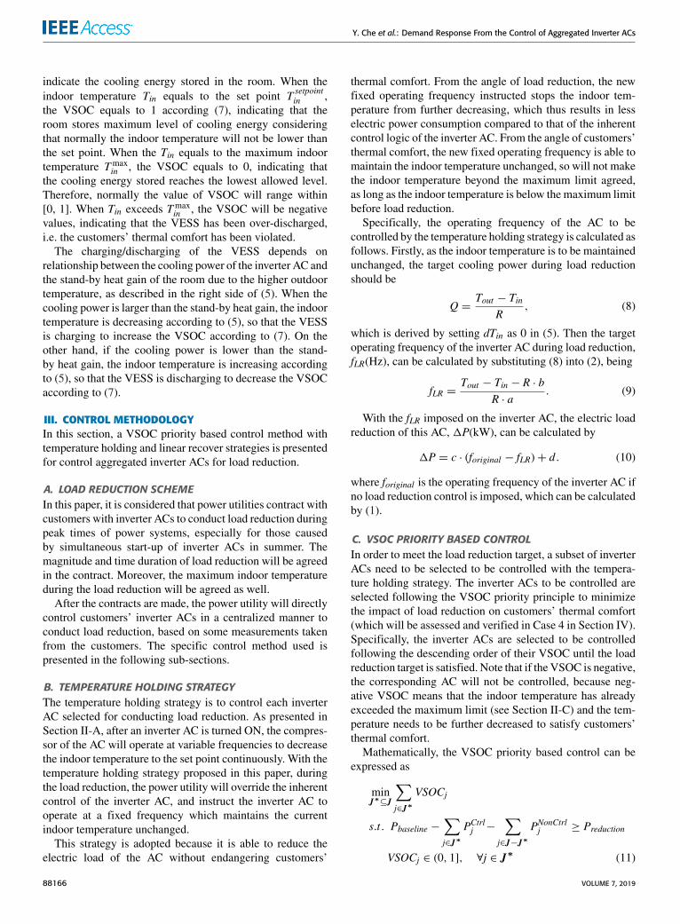
E. THE OVERALL FLOW CHARTThe proposed VSOC priority based load reduction controlmethod with temperature holding and linear recovery strate-gies is summarized as the flow chart shown in Fig. 3.
The flow chart is mainly composed of three parts: loadreduction setting, load recovery setting and control of inverterACs. Once the load reduction is needed, the load reductiontarget and period are set. Then the inverter ACs are con-trolled using the proposed temperature holding strategy in thedescending order of VSOC. If the required amount of loadreduction has been reached, or no more inverter ACs witheligible VSOC level can be controlled, the control in a timestep finishes. This control procedure repeats for each timestep until the load reduction period ends.
After the load reduction ends, the load recovery processstarts, where the load reduction target diminishes graduallyuntil the end of the recovery period. Finally, the whole loadreduction and recovery process ends.
FIGURE 3. The overall flow chart of the proposed load reduction method.
IV. CASE STUDIESIn this section, several case studies are presented to verify theeffectiveness of the proposed load reduction control methodfor inverter ACs.
A. CASE DESIGNThe load reduction of a population of 100 inverter ACs wassimulated and studied. The required amount of load reduction
VOLUME 7, 2019 88167
Y. Che et al.: Demand Response From the Control of Aggregated Inverter ACs
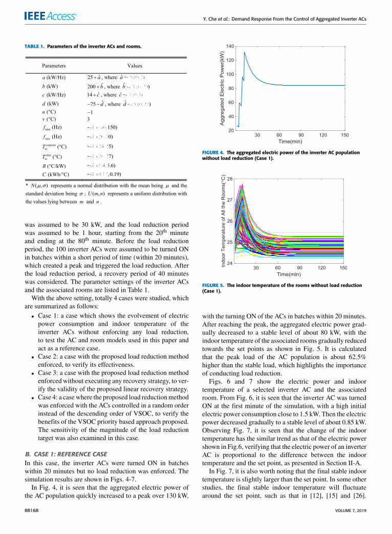
TABLE 1. Parameters of the inverter ACs and rooms.
was assumed to be 30 kW, and the load reduction periodwas assumed to be 1 hour, starting from the 20th minuteand ending at the 80th minute. Before the load reductionperiod, the 100 inverter ACs were assumed to be turned ONin batches within a short period of time (within 20 minutes),which created a peak and triggered the load reduction. Afterthe load reduction period, a recovery period of 40 minuteswas considered. The parameter settings of the inverter ACsand the associated rooms are listed in Table 1.
With the above setting, totally 4 cases were studied, whichare summarized as follows:• Case 1: a case which shows the evolvement of electricpower consumption and indoor temperature of theinverter ACs without enforcing any load reduction,to test the AC and room models used in this paper andact as a reference case.
• Case 2: a case with the proposed load reduction methodenforced, to verify its effectiveness.
• Case 3: a case with the proposed load reduction methodenforcedwithout executing any recovery strategy, to ver-ify the validity of the proposed linear recovery strategy.
• Case 4: a casewhere the proposed load reductionmethodwas enforced with the ACs controlled in a random orderinstead of the descending order of VSOC, to verify thebenefits of the VSOC priority based approach proposed.The sensitivity of the magnitude of the load reductiontarget was also examined in this case.
B. CASE 1: REFERENCE CASEIn this case, the inverter ACs were turned ON in batcheswithin 20 minutes but no load reduction was enforced. Thesimulation results are shown in Figs. 4-7.
In Fig. 4, it is seen that the aggregated electric power ofthe AC population quickly increased to a peak over 130 kW,
FIGURE 4. The aggregated electric power of the inverter AC populationwithout load reduction (Case 1).
FIGURE 5. The indoor temperature of the rooms without load reduction(Case 1).
with the turning ON of the ACs in batches within 20 minutes.After reaching the peak, the aggregated electric power grad-ually decreased to a stable level of about 80 kW, with theindoor temperature of the associated rooms gradually reducedtowards the set points as shown in Fig. 5. It is calculatedthat the peak load of the AC population is about 62.5%higher than the stable load, which highlights the importanceof conducting load reduction.
Figs. 6 and 7 show the electric power and indoortemperature of a selected inverter AC and the associatedroom. From Fig. 6, it is seen that the inverter AC was turnedON at the first minute of the simulation, with a high initialelectric power consumption close to 1.5 kW. Then the electricpower decreased gradually to a stable level of about 0.85 kW.Observing Fig. 7, it is seen that the change of the indoortemperature has the similar trend as that of the electric powershown in Fig.6, verifying that the electric power of an inverterAC is proportional to the difference between the indoortemperature and the set point, as presented in Section II-A.
In Fig. 7, it is also worth noting that the final stable indoortemperature is slightly larger than the set point. In some otherstudies, the final stable indoor temperature will fluctuatearound the set point, such as that in [12], [15] and [26].
88168 VOLUME 7, 2019
Y. Che et al.: Demand Response From the Control of Aggregated Inverter ACs
FIGURE 6. The electric power of one inverter AC without load reduction(Case 1).
FIGURE 7. The indoor temperature of one room without load reduction(Case 1).
This is because a linear function, as used in [19], is usedto describe the relationship between the operating frequencyand electric power of the inverter AC in this paper [see (3)in Section II-A], but in [12], [15] and [26], a more accuratenon-linear function is used. Although a more simplified func-tion is used in this paper, it is sufficient to demonstrateand verify the performance of the load reduction methodproposed. After all, the focus of this paper is not the detailedmodeling of inverter ACs.
C. CASE 2: LOAD REDUCTION CASEIn this case, the load reduction described in the case design(see Section IV-A) was enforced for the AC population. Theresults are shown in Figs. 8-11.
Fig. 8 shows that the load reduction was activated soonafter the peak load was detected, and lasted for 1 hourtill the 80th minute. It is seen that the aggregated powerof the AC population was controlled around 80 kW duringthe load reduction, reducing 30 kW load compared to thetime point when the load reduction was activated. After theload reduction period ended, there was a mild load reboundfor about 40 minutes. Then the aggregated power graduallyconverged to a stable value. Fig. 8 verified that the proposedload reduction method is able to achieve the intended target.
FIGURE 8. The aggregated electric power of the inverter AC populationwith load reduction (Case 2).
FIGURE 9. The indoor temperature of the rooms with load reduction(Case 2).
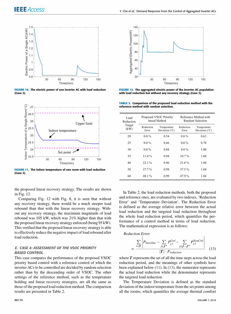
Figs. 10 and 11 show the electric power and indoortemperature of a selected inverter AC and the associatedroom. From Fig. 11, it is seen that the indoor temperaturekept unchanged during the load reduction. This verified thatduring the load reduction, the operating frequency of theinverter AC was reduced to a value which stopped the indoortemperature from further decreasing, as described in the tem-perature holding strategy (see Section III-B). As a result,the electric power of the inverter ACwas reduced accordinglyduring the load reduction, as shown in Fig. 10.
From Fig. 9 where the indoor temperature of all the inverterACs is illustrated, it is seen that the indoor temperature ofsome rooms still decreased in a staircase-like way during theload reduction period. This is because the load reduction wasconducted following a VSOC priority principle. For someACs, at the beginning they might be controlled for loadreduction, but after some time, some other ACs which hadhigher VSOC might take their place so that they were nolonger controlled and re-started to cool the rooms normally.
D. CASE 3: ASSESSMENT OF THE LOADRECOVERY STRATEGYIn this case, the load reduction without any recovery strategyenforced was conducted to demonstrate the effectiveness of
VOLUME 7, 2019 88169
Y. Che et al.: Demand Response From the Control of Aggregated Inverter ACs
FIGURE 10. The electric power of one inverter AC with load reduction(Case 2).
FIGURE 11. The indoor temperature of one room with load reduction(Case 2).
the proposed linear recovery strategy. The results are shownin Fig. 12.
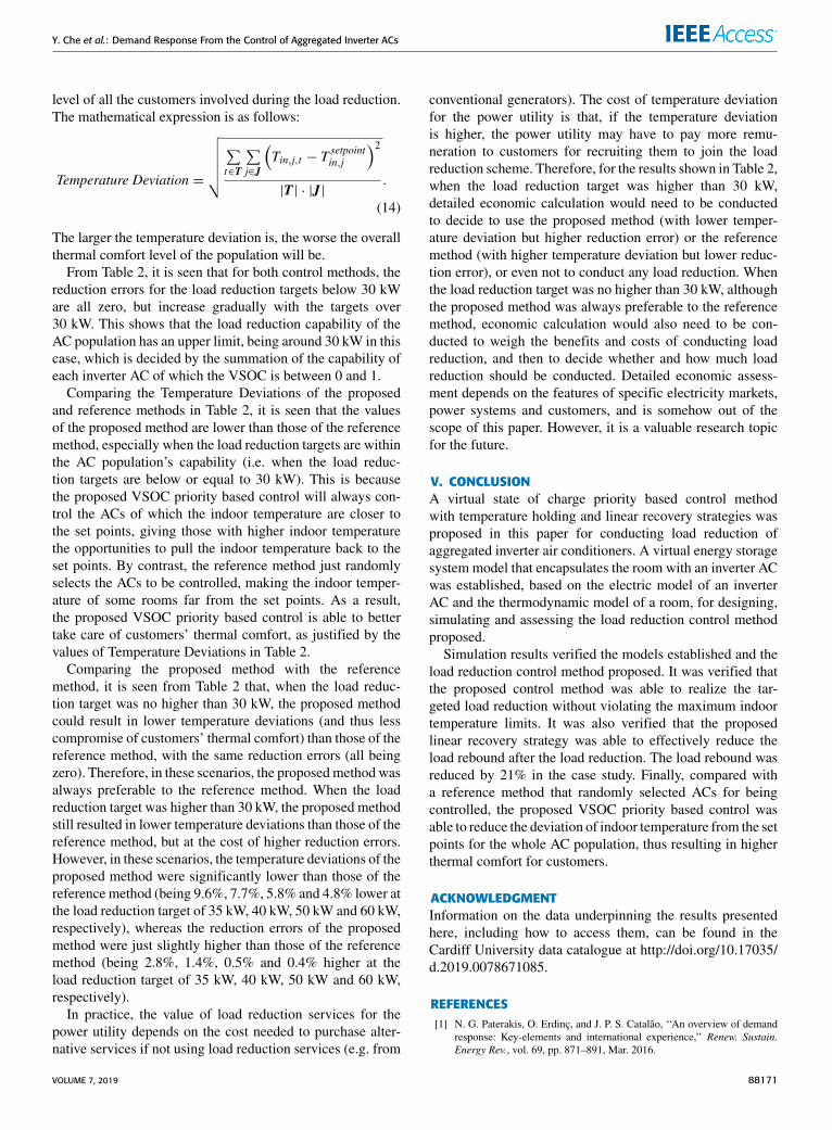
Comparing Fig. 12 with Fig. 8, it is seen that withoutany recovery strategy, there would be a much steeper loadrebound than that with the linear recovery strategy. With-out any recovery strategy, the maximum magnitude of loadrebound was 105 kW, which was 21% higher than that withthe proposed linear recovery strategy enforced (being 95 kW).This verified that the proposed linear recovery strategy is ableto effectively reduce the negative impact of load rebound afterload reduction.
E. CASE 4: ASSESSMENT OF THE VSOC PRIORITYBASED CONTROLThis case compares the performance of the proposed VSOCpriority based control with a reference control of which theinverter ACs to be controlled are decided by random selectionrather than by the descending order of VSOC. The othersettings of the reference method, such as the temperatureholding and linear recovery strategies, are all the same asthose of the proposed load reductionmethod. The comparisonresults are presented in Table 2.
FIGURE 12. The aggregated electric power of the inverter AC populationwith load reduction but without any recovery strategy (Case 3).
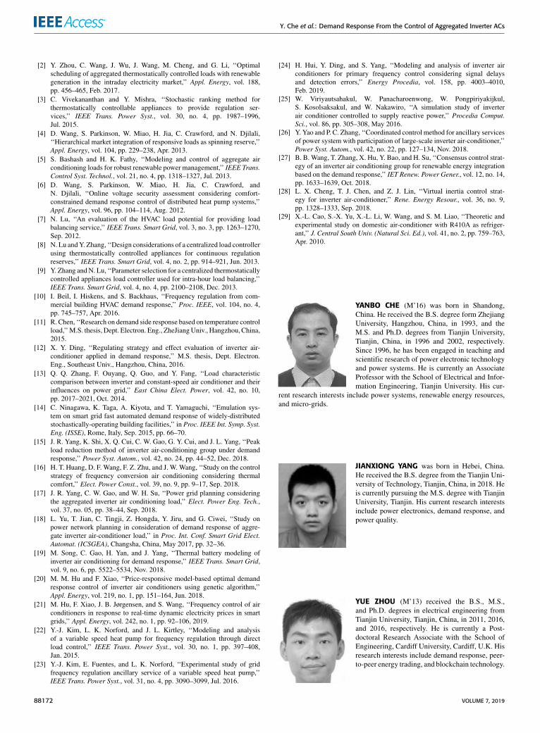
TABLE 2. Comparison of the proposed load reduction method with thereference method with random selection.
In Table 2, the load reduction methods, both the proposedand reference ones, are evaluated by two indexes, ‘ReductionError’ and ‘Temperature Deviation’. The Reduction Erroris defined as the average relative error between the actualload reduction and the targeted load reduction throughoutthe whole load reduction period, which quantifies the per-formance of a control method in terms of load reduction.The mathematical expression is as follows:
Reduction Error
=
∑t∈T
∣∣∣∣∣Pbaseline − ∑j∈J∗
PCtrlj,t −∑
j∈J−J∗PNonCtrlj,t
∣∣∣∣∣|T | · Preduction
(13)
where T represents the set of all the time steps across the loadreduction period, and the meanings of other symbols havebeen explained below (11). In (13), the numerator representsthe actual load reduction while the denominator representsthe targeted load reduction.
The Temperature Deviation is defined as the standarddeviation of the indoor temperature from the set points amongall the rooms, which quantifies the average thermal comfort
88170 VOLUME 7, 2019
Y. Che et al.: Demand Response From the Control of Aggregated Inverter ACs
level of all the customers involved during the load reduction.The mathematical expression is as follows:
Temperature Deviation =
√√√√√∑t∈T
∑j∈J
(Tin,j,t − T
setpointin,j
)2|T | · |J |
.
(14)
The larger the temperature deviation is, the worse the overallthermal comfort level of the population will be.
From Table 2, it is seen that for both control methods, thereduction errors for the load reduction targets below 30 kWare all zero, but increase gradually with the targets over30 kW. This shows that the load reduction capability of theAC population has an upper limit, being around 30 kW in thiscase, which is decided by the summation of the capability ofeach inverter AC of which the VSOC is between 0 and 1.
Comparing the Temperature Deviations of the proposedand reference methods in Table 2, it is seen that the valuesof the proposed method are lower than those of the referencemethod, especially when the load reduction targets are withinthe AC population’s capability (i.e. when the load reduc-tion targets are below or equal to 30 kW). This is becausethe proposed VSOC priority based control will always con-trol the ACs of which the indoor temperature are closer tothe set points, giving those with higher indoor temperaturethe opportunities to pull the indoor temperature back to theset points. By contrast, the reference method just randomlyselects the ACs to be controlled, making the indoor temper-ature of some rooms far from the set points. As a result,the proposed VSOC priority based control is able to bettertake care of customers’ thermal comfort, as justified by thevalues of Temperature Deviations in Table 2.
Comparing the proposed method with the referencemethod, it is seen from Table 2 that, when the load reduc-tion target was no higher than 30 kW, the proposed methodcould result in lower temperature deviations (and thus lesscompromise of customers’ thermal comfort) than those of thereference method, with the same reduction errors (all beingzero). Therefore, in these scenarios, the proposedmethod wasalways preferable to the reference method. When the loadreduction target was higher than 30 kW, the proposed methodstill resulted in lower temperature deviations than those of thereference method, but at the cost of higher reduction errors.However, in these scenarios, the temperature deviations of theproposed method were significantly lower than those of thereference method (being 9.6%, 7.7%, 5.8% and 4.8% lower atthe load reduction target of 35 kW, 40 kW, 50 kW and 60 kW,respectively), whereas the reduction errors of the proposedmethod were just slightly higher than those of the referencemethod (being 2.8%, 1.4%, 0.5% and 0.4% higher at theload reduction target of 35 kW, 40 kW, 50 kW and 60 kW,respectively).
In practice, the value of load reduction services for thepower utility depends on the cost needed to purchase alter-native services if not using load reduction services (e.g. from
conventional generators). The cost of temperature deviationfor the power utility is that, if the temperature deviationis higher, the power utility may have to pay more remu-neration to customers for recruiting them to join the loadreduction scheme. Therefore, for the results shown in Table 2,when the load reduction target was higher than 30 kW,detailed economic calculation would need to be conductedto decide to use the proposed method (with lower temper-ature deviation but higher reduction error) or the referencemethod (with higher temperature deviation but lower reduc-tion error), or even not to conduct any load reduction. Whenthe load reduction target was no higher than 30 kW, althoughthe proposed method was always preferable to the referencemethod, economic calculation would also need to be con-ducted to weigh the benefits and costs of conducting loadreduction, and then to decide whether and how much loadreduction should be conducted. Detailed economic assess-ment depends on the features of specific electricity markets,power systems and customers, and is somehow out of thescope of this paper. However, it is a valuable research topicfor the future.
V. CONCLUSIONA virtual state of charge priority based control methodwith temperature holding and linear recovery strategies wasproposed in this paper for conducting load reduction ofaggregated inverter air conditioners. A virtual energy storagesystem model that encapsulates the room with an inverter ACwas established, based on the electric model of an inverterAC and the thermodynamic model of a room, for designing,simulating and assessing the load reduction control methodproposed.
Simulation results verified the models established and theload reduction control method proposed. It was verified thatthe proposed control method was able to realize the tar-geted load reduction without violating the maximum indoortemperature limits. It was also verified that the proposedlinear recovery strategy was able to effectively reduce theload rebound after the load reduction. The load rebound wasreduced by 21% in the case study. Finally, compared witha reference method that randomly selected ACs for beingcontrolled, the proposed VSOC priority based control wasable to reduce the deviation of indoor temperature from the setpoints for the whole AC population, thus resulting in higherthermal comfort for customers.
ACKNOWLEDGMENTInformation on the data underpinning the results presentedhere, including how to access them, can be found in theCardiff University data catalogue at http://doi.org/10.17035/d.2019.0078671085.
REFERENCES[1] N. G. Paterakis, O. Erdinç, and J. P. S. Catalão, ‘‘An overview of demand
response: Key-elements and international experience,’’ Renew. Sustain.Energy Rev., vol. 69, pp. 871–891, Mar. 2016.
VOLUME 7, 2019 88171
Y. Che et al.: Demand Response From the Control of Aggregated Inverter ACs
[2] Y. Zhou, C. Wang, J. Wu, J. Wang, M. Cheng, and G. Li, ‘‘Optimalscheduling of aggregated thermostatically controlled loads with renewablegeneration in the intraday electricity market,’’ Appl. Energy, vol. 188,pp. 456–465, Feb. 2017.
[3] C. Vivekananthan and Y. Mishra, ‘‘Stochastic ranking method forthermostatically controllable appliances to provide regulation ser-vices,’’ IEEE Trans. Power Syst., vol. 30, no. 4, pp. 1987–1996,Jul. 2015.
[4] D. Wang, S. Parkinson, W. Miao, H. Jia, C. Crawford, and N. Djilali,‘‘Hierarchical market integration of responsive loads as spinning reserve,’’Appl. Energy, vol. 104, pp. 229–238, Apr. 2013.
[5] S. Bashash and H. K. Fathy, ‘‘Modeling and control of aggregate airconditioning loads for robust renewable power management,’’ IEEE Trans.Control Syst. Technol., vol. 21, no. 4, pp. 1318–1327, Jul. 2013.
[6] D. Wang, S. Parkinson, W. Miao, H. Jia, C. Crawford, andN. Djilali, ‘‘Online voltage security assessment considering comfort-constrained demand response control of distributed heat pump systems,’’Appl. Energy, vol. 96, pp. 104–114, Aug. 2012.
[7] N. Lu, ‘‘An evaluation of the HVAC load potential for providing loadbalancing service,’’ IEEE Trans. Smart Grid, vol. 3, no. 3, pp. 1263–1270,Sep. 2012.
[8] N. Lu andY. Zhang, ‘‘Design considerations of a centralized load controllerusing thermostatically controlled appliances for continuous regulationreserves,’’ IEEE Trans. Smart Grid, vol. 4, no. 2, pp. 914–921, Jun. 2013.
[9] Y. Zhang andN. Lu, ‘‘Parameter selection for a centralized thermostaticallycontrolled appliances load controller used for intra-hour load balancing,’’IEEE Trans. Smart Grid, vol. 4, no. 4, pp. 2100–2108, Dec. 2013.
[10] I. Beil, I. Hiskens, and S. Backhaus, ‘‘Frequency regulation from com-mercial building HVAC demand response,’’ Proc. IEEE, vol. 104, no. 4,pp. 745–757, Apr. 2016.
[11] R. Chen, ‘‘Research on demand side response based on temperature controlload,’’M.S. thesis, Dept. Electron. Eng., ZheJiangUniv., Hangzhou, China,2015.
[12] X. Y. Ding, ‘‘Regulating strategy and effect evaluation of inverter air-conditioner applied in demand response,’’ M.S. thesis, Dept. Electron.Eng., Southeast Univ., Hangzhou, China, 2016.
[13] Q. Q. Zhang, F. Ouyang, Q. Guo, and Y. Fang, ‘‘Load characteristiccomparison between inverter and constant-speed air conditioner and theirinfluences on power grid,’’ East China Elect. Power, vol. 42, no. 10,pp. 2017–2021, Oct. 2014.
[14] C. Ninagawa, K. Taga, A. Kiyota, and T. Yamaguchi, ‘‘Emulation sys-tem on smart grid fast automated demand response of widely-distributedstochastically-operating building facilities,’’ in Proc. IEEE Int. Symp. Syst.Eng. (ISSE), Rome, Italy, Sep. 2015, pp. 66–70.
[15] J. R. Yang, K. Shi, X. Q. Cui, C. W. Gao, G. Y. Cui, and J. L. Yang, ‘‘Peakload reduction method of inverter air-conditioning group under demandresponse,’’ Power Syst. Autom., vol. 42, no. 24, pp. 44–52, Dec. 2018.
[16] H. T. Huang, D. F. Wang, F. Z. Zhu, and J. W. Wang, ‘‘Study on the controlstrategy of frequency conversion air conditioning considering thermalcomfort,’’ Elect. Power Const., vol. 39, no. 9, pp. 9–17, Sep. 2018.
[17] J. R. Yang, C. W. Gao, and W. H. Su, ‘‘Power grid planning consideringthe aggregated inverter air conditioning load,’’ Elect. Power Eng. Tech.,vol. 37, no. 05, pp. 38–44, Sep. 2018.
[18] L. Yu, T. Jian, C. Tingji, Z. Hongda, Y. Jiru, and G. Ciwei, ‘‘Study onpower network planning in consideration of demand response of aggre-gate inverter air-conditioner load,’’ in Proc. Int. Conf. Smart Grid Elect.Automat. (ICSGEA), Changsha, China, May 2017, pp. 32–36.
[19] M. Song, C. Gao, H. Yan, and J. Yang, ‘‘Thermal battery modeling ofinverter air conditioning for demand response,’’ IEEE Trans. Smart Grid,vol. 9, no. 6, pp. 5522–5534, Nov. 2018.
[20] M. M. Hu and F. Xiao, ‘‘Price-responsive model-based optimal demandresponse control of inverter air conditioners using genetic algorithm,’’Appl. Energy, vol. 219, no. 1, pp. 151–164, Jun. 2018.
[21] M. Hu, F. Xiao, J. B. Jørgensen, and S. Wang, ‘‘Frequency control of airconditioners in response to real-time dynamic electricity prices in smartgrids,’’ Appl. Energy, vol. 242, no. 1, pp. 92–106, 2019.
[22] Y.-J. Kim, L. K. Norford, and J. L. Kirtley, ‘‘Modeling and analysisof a variable speed heat pump for frequency regulation through directload control,’’ IEEE Trans. Power Syst., vol. 30, no. 1, pp. 397–408,Jan. 2015.
[23] Y.-J. Kim, E. Fuentes, and L. K. Norford, ‘‘Experimental study of gridfrequency regulation ancillary service of a variable speed heat pump,’’IEEE Trans. Power Syst., vol. 31, no. 4, pp. 3090–3099, Jul. 2016.
[24] H. Hui, Y. Ding, and S. Yang, ‘‘Modeling and analysis of inverter airconditioners for primary frequency control considering signal delaysand detection errors,’’ Energy Procedia, vol. 158, pp. 4003–4010,Feb. 2019.
[25] W. Viriyautsahakul, W. Panacharoenwong, W. Pongpiriyakijkul,S. Kosolsaksakul, and W. Nakawiro, ‘‘A simulation study of inverterair conditioner controlled to supply reactive power,’’ Procedia Comput.Sci., vol. 86, pp. 305–308, May 2016.
[26] Y. Yao and P. C. Zhang, ‘‘Coordinated control method for ancillary servicesof power system with participation of large-scale inverter air-conditioner,’’Power Syst. Autom., vol. 42, no. 22, pp. 127–134, Nov. 2018.
[27] B. B. Wang, T. Zhang, X. Hu, Y. Bao, and H. Su, ‘‘Consensus control strat-egy of an inverter air conditioning group for renewable energy integrationbased on the demand response,’’ IET Renew. Power Gener., vol. 12, no. 14,pp. 1633–1639, Oct. 2018.
[28] L. X. Cheng, T. J. Chen, and Z. J. Lin, ‘‘Virtual inertia control strat-egy for inverter air-conditioner,’’ Rene. Energy Resour., vol. 36, no. 9,pp. 1328–1333, Sep. 2018.
[29] X.-L. Cao, S.-X. Yu, X.-L. Li, W. Wang, and S. M. Liao, ‘‘Theoretic andexperimental study on domestic air-conditioner with R410A as refriger-ant,’’ J. Central South Univ. (Natural Sci. Ed.), vol. 41, no. 2, pp. 759–763,Apr. 2010.
YANBO CHE (M’16) was born in Shandong,China. He received the B.S. degree form ZhejiangUniversity, Hangzhou, China, in 1993, and theM.S. and Ph.D. degrees from Tianjin University,Tianjin, China, in 1996 and 2002, respectively.Since 1996, he has been engaged in teaching andscientific research of power electronic technologyand power systems. He is currently an AssociateProfessor with the School of Electrical and Infor-mation Engineering, Tianjin University. His cur-
rent research interests include power systems, renewable energy resources,and micro-grids.
JIANXIONG YANG was born in Hebei, China.He received the B.S. degree from the Tianjin Uni-versity of Technology, Tianjin, China, in 2018. Heis currently pursuing the M.S. degree with TianjinUniversity, Tianjin. His current research interestsinclude power electronics, demand response, andpower quality.
YUE ZHOU (M’13) received the B.S., M.S.,and Ph.D. degrees in electrical engineering fromTianjin University, Tianjin, China, in 2011, 2016,and 2016, respectively. He is currently a Post-doctoral Research Associate with the School ofEngineering, Cardiff University, Cardiff, U.K. Hisresearch interests include demand response, peer-to-peer energy trading, and blockchain technology.
88172 VOLUME 7, 2019

Y. Che et al.: Demand Response From the Control of Aggregated Inverter ACs
YUANCHENG ZHAO was born in Shandong,China. He received the B.S. degree from HunanUniversity, Changsha, China, in 2016, and theM.S. degree from Tianjin University, Tianjin,China, in 2019. His research interests includepower electronics, demand response, and powerquality.
WEI HE was born in Hubei, China. He receivedthe B.S. degree from Wuhan University, Wuhan,China, in 2007, and the M.S. and Ph.D. degreesin electrical engineering from North China Elec-tric Power University, Hebei, China, in 2009 and2013, respectively. He is currently a Senior Engi-neer with the State Grid Jiangxi Electric PowerResearch Institute, Nanchang, Jiangxi, China. Hiscurrent research interests include power qualityand smart grid.
JIANZHONG WU (M’04) received the B.S., M.S.,and Ph.D. degrees in electrical engineering fromTianjin University, China, in 1999, 2002, and2004, respectively.
From 2004 to 2006, he held a postdoctoral posi-tion at Tianjin University. From 2006 to 2008,he was a Research Fellow with The Universityof Manchester, U.K. He joined Cardiff Univer-sity, U.K., as a Lecturer, in 2008, a Senior Lec-turer, in 2013, a Reader, in 2014, and a Professor,
in 2015. He is currently a Professor of multi-vector energy systems and theHead of the Department of Electrical and Electronic Engineering, CardiffUniversity. He is also the Director of Applied Energy UNiLAB on SynergiesBetween Energy Networks. He is also a Co-Director of EPSRC SupergenEnergy Networks Hub and the U.K. Energy Research Centre. His researchinterests include energy infrastructure and smart grid. He is also a SubjectEditor of Applied Energy.
VOLUME 7, 2019 88173