Embed Size (px)
Citation preview

deltapilot SElectronic InsertFEB 24 (P) withPROFIBUS-PA ProtocolOperating Instructions
BA 164F/00/en/09.97aSoftware Version 1.0017141-1000
Hauser+EndressThe Power of Know How
%
V H+
V HLocal operationDeltapilot Swith display
Remote operation viaCommuwin II*of Deltapilot S with/without display
Matrix operation: Chapter 3
Level orpressure?
Pressure
Level
Chapter 4.1Calibrationwith emptyand full tank
Chapter 4.2Drycalibration
Chapter 5Pressureand ∆p-measurement
Signaland displayin technical
units?
horizontal table
Chapter 4.4/4.5/4.6Other settings,locking andmeasured valuedisplay
no
yes
LinearisationChapter 4.3
Short Instructions
Short Instructions Deltapilot S PA
Endress+Hauser

Table of Contents
Software History . . . . . . . . . . 2
Notes on Safety . . . . . . . . . . . 3
1 Introduction . . . . . . . . . . . . 51.1 Measuring system . . . . . . . . 6
2 Installation . . . . . . . . . . . . . 72.1 Installation hints . . . . . . . . . 72.2 Connection . . . . . . . . . . . 92.3 Device parameter file/type file . . . 10
3 Operation . . . . . . . . . . . . . 113.1 Operating and display module FHB 20 113.2 Remote operation with Commuwin II . 123.3 Data acquisition via PLC . . . . . 13
4 Level Measurement . . . . . . . . . 154.1 Empty/full calibration . . . . . . . 154.2 Dry calibration . . . . . . . . . 174.3 Linearisation . . . . . . . . . . 184.4 Other settings . . . . . . . . . . 204.5 Locking/unlocking the matrix . . . . 214.6 Measuring point information . . . . 22
5 Pressure and Differential Pressure . . . 23
6 Trouble-Shooting . . . . . . . . . . 256.1 Simulation . . . . . . . . . . . 266.2 Reset to factory settings . . . . . . 276.3 Exchange of the electronic insert or
measuring cell . . . . . . . . . 286.4 Repairs . . . . . . . . . . . . 28
7 PROFIBUS-PA Parameters . . . . . . 29
8 Technical Data . . . . . . . . . . . 31
9 Operating Matrix . . . . . . . . . . 33
Index . . . . . . . . . . . . . . . 34
Deltapilot S PA Table of Contents
1

Software History
Software Change Significance
1.0 Original software DPV1
Software History Deltapilot S PA
2
Notes on Safety
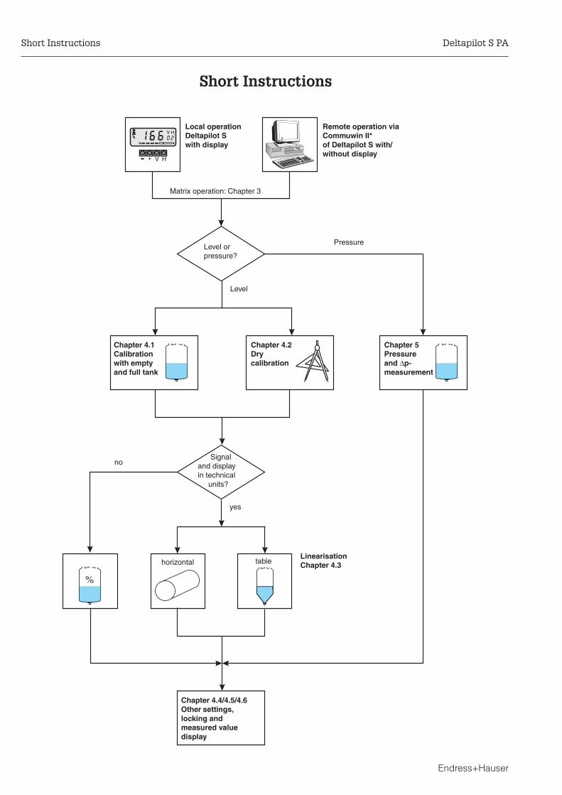
Approved usageThe hydrostatic pressure sensor Deltapilot S with electronic insert FEB 24 (P) is aPROFIBUS PA device which is used for continuous level measurement. It can also beused to measure pressure and differential pressure (by using a PLC and second sensor).
Installation,commissioning,operation
The Deltapilot S has been designed to operate safely in accordance with currenttechnical, safety and EU standards. If installed incorrectly or used for applications forwhich it is not intended, however, it is possible that application-related dangers may arise,e.g. product overflow due to incorrect installation or calibration. For this reason, theinstrument must be installed, connected, operated and maintained according to theinstructions in this manual: personnel must be authorised and suitably qualified. Themanual must have been read and understood, and the instructions followed.Modifications and repairs to the device are permissible only when they are expresslyapproved in the manual.
Explosion hazardousareas
If the device is to be installed in an explosion hazardous area, then the specifications inthe certificate as well as all national and local regulations must be observed. Theinstrument can be delivered with the certificates listed in the table below. The certificatecan be identified from the first letter of the order code stamped on the nameplate.
• Ensure that all personnel are suitably qualified• Observe the specifications in the certificate as well as national and local
regulations.• Take special care with regard to the grounding of the bus cable screening.
Recommendations are to be found in IEC 79–14.
Code Certificate Explosion protection
A Standard none
C PTB EEx ia IIC T6, Zone 0 FRG
G PTB EEx ia IIC T6
Tabelle S.1Certificates for applications inexplosion hazardous areas
ENDRESS+HAUSERDELTAPILOT S DB 5x
Order No. DB 5x x
Deltapilot S PA Notes on Safety
Endress+Hauser 3
Safety Conventions and Symbols
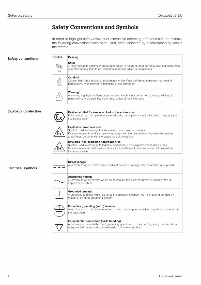
In order to highlight safety-relevant or alternative operating procedures in the manual,the following conventions have been used, each indicated by a corresponding icon inthe margin.
Safety conventions
Explosion protection
Electrical symbols
Symbol Meaning
Note!A note highlights actions or procedures which, if not performed correctly, may indirectly affectoperation or may lead to an instrument response which is not planned
Caution!Caution highlights actions or procedures which, if not performed correctly, may lead topersonal injury or incorrect functioning of the instrument
Warning!A warning highlights actions or procedures which, if not performed correctly, will lead topersonal injury, a safety hazard or destruction of the instrument
Device certified for use in explosion hazardous areaIf the device has this symbol embossed on its name plate it can be installed in an explosionhazardous area
Explosion hazardous areaSymbol used in drawings to indicate explosion hazardous areas.Devices located in and wiring entering areas with the designation “explosion hazardousareas” must conform with the stated type of protection
Safe area (non-explosion hazardous area)Symbol used in drawings to indicate, if necessary, non-explosion hazardous areas.Devices located in safe areas stiill require a certificate if their outputs run into explosionhazardous areas.
Direct voltageA terminal to which or from which a direct current or voltage may be applied or supplied
Alternating voltageA terminal to which or from which an alternating (sine-wave) current or voltage may beapplied or supplied
Grounded terminalA grounded terminal, which as far as the operator is concerned, is already grounded bymeans of an earth grounding system
Protective grounding (earth) terminalA terminal which must be connected to earth ground prior to making any other connection tothe equipment
Equipotential connection (earth bonding)A connection made to the plant grounding system which may be of type e.g. neutral star orequipotential line according to national or company practice
Note!
Warning!
Caution!
Notes on Safety Deltapilot S PA
4 Endress+Hauser

1 Introduction
ApplicationThe electronic insert FEB 24 (P) serves as transmitter for the hydrostatic pressure sensorsDeltapilot S DB 50, DB 50 L, DB 51, DB 52 and DB 53. Deltapilot S sensors are used forcontinuous level measurement of liquids and pastes. They find application in thechemical, pharmaceutical and food industries as well as in fresh and wastewatertreatment plants.
Operating principleThe level of a column of liquid of knowndensity ρ can be determined by measuringits hydrostatic pressure with a suitablesensor.
h = phydr/ρ·g
The pressure sensor Delltapilot S convertsthe pressure acting upon its processdiaphragm into an electrical signal. Theelectronic insert takes this signal andoutputs it as a direct digital signal.
For level measurement in a pressurisedvessel or differential pressuremeasurement, the head pressure must bemeasured with a second sensor. Thehydrostatic pressure is then corrected bythe connected programmable logiccontroller.
Version with rodextension
Version with ropeextension DB 52
Compact versionDB 50
BA
164Y
03 Version for food and pharma-ceutical industries DB 50 L
Version for water andwastewater industriesDB 53
Fig. 1.1Deltapilot pressure sensorversions
phydr
h
patm
patm
phydr
h
pgas
patm
BA
164Y
04
Fig. 1.2Principle of hydrostatic level measurement
Deltapilot S PA 1 Introduction
Endress+Hauser 5

1.1 Measuring system
In the simplest case, the complete measuring system comprises a Deltapilot S withelectronic insert FEB 24 (P), a bus coupler, a PLC or personal computer with the operatingprogram Commuwin II as well as a PROFIBUS PA terminating resistor.
The maximum number of transmitters on a bus segment is determined by their currentconsumption, the power of the bus coupler and the required bus length, seeTI 260F/00/en. Normally, however:
• 10 Deltapilot S for EEx ia applications• max. 32 Deltapilot S for non-hazardous applications
can be operated on a bus segment.
ENDRESS + HAUSER
personal computerwith operatingprogram, e.g.Commuwin II
tanks with Deltapilot Spressure sensors
PLC
BA
164Y
05
fieldbus withPROFIBUS PA
segmentcoupler
PROFIBUS DP
Fig. 1.3Deltapilot S measuring systemwith PROFIBUS PA protocol
1 Introduction Deltapilot S PA
6 Endress+Hauser

2 Installation
This chapter describes:• the mechanical installation of the Deltapilot S sensor• the connection of the electronic insert• the setting of the device address• the installation of the device parameter file in the PLC
2.1 Installation hints
LocationCompact version• The DB 50 must always be installed
beneath the lowest point ofmeasurement.
• It should not be installed in the fillingcurtain, the tank outlet or at a position inthe tank which is affected by pressurepulses from a stirrer.
• Calibration and function testing aremore easily carried out when the DB 50is mounted downstream of a cut-offvalve.
Rod and rope version• The rope version should be mounted at
a point which is as free as possiblefrom currents and turbulence. In orderto protect the sensor from knocks dueto lateral movement, it can be mountedin a stilling well (preferrably plastic) orbraced from the cross-anchor provided.
• The zero point of the level measurementdetermines the length of the supportcable orsensor rod. The tip of the probeshould be at least 5 cm (2") below thislevel.
• When installed in a domed manhole,the sensor should be mounted in anozzle to prevent the housing frombeing flooded by moisture orcondensation.
Process diaphragm• The process diaphragm is not to behandled or cleaned with hard orpointed objects. Measurement is notaffected by build-up, provided that itremains elastic and transmits thehydrostatic pressure.
• All rope and rod versions of theDeltapilot S are supplied with a plasticcap which protects the processdiaphragm from mechanical damage.
Effect of temperature• For media which harden when cold, theDeltapilot S must be covered by thetank insulation. Alternatively a rod orrope version can be used.
BA164Y09
BA164Y10
BA164Y11
Deltapilot S PA 2 Installation
Endress+Hauser 7
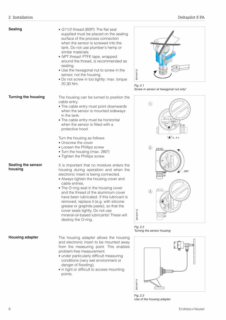
Sealing • G11/2 thread (BSP): The flat sealsupplied must be placed on the sealingsurface of the process connectionwhen the sensor is screwed into thetank, Do not use plumber's hemp orsimilar materials.
• NPT thread: PTFE tape, wrappedaround the thread, is recommended assealing.
• Use the hexagonal nut to screw in thesensor, not the housing.
• Do not screw in too tightly: max. torque20…30 Nm.
Turning the housing The housing can be turned to position thecable entry.• The cable entry must point downwards
when the sensor is mounted sidewaysin the tank.
• The cable entry must be horizontalwhen the sensor is fitted with aprotective hood.
Turn the housing as follows:• Unscrew the cover• Loosen the Phillips screw• Turn the housing (max. 280°)• Tighten the Phillips screw.
Sealing the sensorhousing
It is important that no moisture enters thehousing during operatiion and when theelectronic insert is being connected.• Always tighten the housing cover and
cable entries.• The O-ring seal in the housing cover
and the thread of the aluminium coverhave been lubricated. If this lubricant isremoved, replace it (e.g. with siliconegrease or graphite paste), so that thecover seals tightly. Do not usemineral-oil-based lubricants! These willdestroy the O-ring.
Housing adapter The housing adapter allows the housingand electronic insert to be mounted awayfrom the measuring point. This enablesproblem-free measurement:• under particularly difficult measuring
conditions (very wet environment ordanger of flooding).
• in tight or difficult to access mountingpoints.
BA
164Y
12
Fig. 2.1Screw in sensor at hexagonal nut only!
1.
3...4 x
... 280°
++1 2 3 4
4…20 mADAT-Modul
–
–
FHB 20
GREENGREEN RED
2.
3.
++
++
11
22
33
44
4…20m
A4…20
mA
DAT-M
odulD
AT-Modul
––
––
FH
B20
FH
B20
GR
EE
NG
RE
EN
RE
DR
ED
BA
164Y
13
Fig. 2.2Turning the sensor housing
BA
164Y
14
Fig. 2.3Use of the housing adapter
2 Installation Deltapilot S PA
8 Endress+Hauser

2.2 Connection
Bus cableFor new installations a cable comprising screened, twisted pairs is recommended. Thefollowing specifications must be met for explosion-hazardous applications (EN 50 020,FISCO model):
• Loop resistance (DC) 15...150 Ω /km. specific inductance 0.4...1 mH/km,specific capacitance 80...200 nF/km, e.g. Siemens 6XV1 830-5AH10 (blue)
• None hazardous areas, e.g. Kerpen CEL-PE/OSCR/PVC/FRLA FB-02YS(ST)YFL,Belden 3076F, Siemens 6XV1 830-5BH10 (black)
Information on the structure and grounding of the network are given in TI260/00/en"Planning Hints, PROFIBUS PA" and the PROFIBUS PA specification.
Cable connectionThe bus line also carries the power and isconnected as follows:• Remove housing cover• Where appropriate, remove display
module FHB 20 by turning with lightpressure to left
• Thread cable through cable entry
Connect cable as shown:• Connect cable cores to PA+ und PA– .
Reversed polarity has no effect onoperation
• Connect the screen to the externalground terminal
• For FEB 24 P always connect externalground terminal to plant groundingsystem.
Caution!The multiple grounding of the bus cable inexplosion hazardous areas is permissibleonly under specific conditions, see TI 260For IEC 79-14.
Bus addressEvery device is given a unique busaddress. Normally, the bus address is setat a DIP-switch on the device.• Lift protective flap• Set address (0...126) at switches 1...7• Set switch 8 to OFF
Address = address at switchON: address = software address
• Switch device off and on to register thechange in address.
After connecting the bus cable and settingthe address, if appropriate clip FHB 20 inposition, and screw on cover.• The display orientation can be changed
(turn 90° anticlockwise).
PA- PA+
Alarm LED
1 2 3 4 5 6 7 8
DAT-Modul
FHB 20
V H+
V H
BA
164Y
15
Terminals
Address switch
DAT datamodule
FHB 20
PA-
PA-
PA+
PA+
Alarm LED
1 2 3 4 5 6 7 8
DAT-Modul
FHB 20
BA
164Y
16
1 2 3 4 5 6 7 8
ON
OFF
2 + 8 = 10
BA
164Y
17
OFF: Hardware addressON: Software address
Caution!
Deltapilot S PA 2 Installation
Endress+Hauser 9
2.3 Device parameter file/type file
A diskette with the device data base .DDB is delivered with every device type. The filesmust be loaded into the communications partner during the commissioning of the system.
The diskette also contains a so-called TYP file for specific Siemens host systemconfiguration tools, e.g. COM ET 200 or COM PROFIBUS. For these tools, the files shouldbe stored as follows:
• all files with extender *.200 in the type file directory, e.g. ***\TYPDAT5X
• all files with extender *.GSD in the data parameter file directory, e.g. ***\GSD
• all files with extender *.BMP in the bit maps directory, e.g. ***\BITMAPS.
The significance of the individual parameters is described in the PROFIBUS-PAspecification.
.
2 Installation Deltapilot S PA
10 Endress+Hauser
3 Operation
Operating matrixThe Deltapilot S is configured and operated via a 10 x 10 matrix.
• Each row is allocated to a particular function,• Each field sets or displays one parameter.
The same matrix is used, irrespective of whether the operating and display module FHBor the operating program Commuwin II is used. It is to be found in Chapter 9. In the caseof cyclic and acyclic scanning of parameters via PLC, the measured values areaddressed by means of variable names which are defined in the PROFIBUS PA profile.
3.1 Operating and display module FHB 20
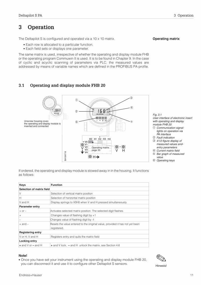
If ordered, the operating and display module is stowed away in in the housing. It functionsas follows:
Note!• Once you have set your instrument using the operating and display module FHB 20,
you can disconnect it and use it to configure other Deltapilot S sensors.
Keys Function
Selection of matrix field
V Selection of vertical matrix position
H Selection of horizontal matrix position
V and H Display springs to V0H0 when V and H pressed simultaneously
Parameter entry
+ or – Activates selected matrix position. The selected digit flashes.
+ Changes value of flashing digit by +1
– Changes value of flashing digit by –1
+ and – Resets the value entered to the original value, provided it has not yet been
registered.
Registering entry
V or H; V and H Registers entry and quits the matrix field
Locking entry
+ and V or – and H + and V lock, – and H unlock the matrix, see Section 4.6
V H+
VV HH
V H+
V H
VV H
H
+
+
V H V H
➂➀
➁
Operating matrixpage 33
➅
➃
➄Unscrew housing cover,the operating and display module isinserted and connected
BA
164Y
18
Fig. 3.1User interface of electronic insertwith operating and displaymodule FHB 20➀ Communication signal:
lights on operation viaPA interface
➁ Fault indication➂ 41/2-figure display of
measured values and-entry parameters
➃ Current matrix field➄ Bar graph of measured
value➅ Operating keys
Hinweis!
Deltapilot S PA 3 Operation
Endress+Hauser 11

3.2 Remote operation with Commuwin II
PROFIBUS-PA devices can be operated with Commuwin II operating program versionsfrom 1.5 upwards. A full description of Commuwin II is to be found in operatinginstructions BA 124F. The transmitter is configured either via the operating matrix (seeFig. 3.2) or the graphic interface (Fig. 3.3).
Open connection Remote operation requires the installation of the PROFIBUS-PA server and the personalcomputer requires a PROFIBUS-DP card.
• The connection in Commuwin II is made via the PROFIBUS-PA server• All devices on the relevant segment appear in the live list.• The transmitter configuration is entered in the device menu• PROFIBUS-PA profile parameters can be viewed and set under the graphic
interface
Note!• Deltapilot S transmitters can also be configured on site via the keys. If the keys have
been used to lock configuration, the transmitter cannot be remotely configured, butthe parameters can be displayed.Note!
V1
V Calibration0 0EMPTY CALIBRATION
100FULL CALIBRATION
0LINEARISATION2CALIBRATION MODE
0LOWER RANGE-LIMIT
100UPPER RANGE-LIMIT
95MAX. PRESSURE
1TABLE NO.0UNITS DRY CALIBR.
0ENTER LEVEL1.00DENSITY FACTOR
80.5%MEASURED VALUE
V Linearisation2
V Ent. calibration3
V4
V5
V6
V Sensor data7
FEB 24PROFIBUS-PA
BA
164E
36
Fig. 3.2Parameter matrix menu inCommuwin II
Graphic support - status
MEASURING POINT
LIC 006
DIAGNOSIS CODE
0
MEASURED VALUE
Endress+Hauser Deltapilot S (FEB 24)
80.3
DEVICE+SOFTW
XXXX
BA
164E
35
Fig. 3.3Graphic support menu inCommuwin II
3 Operation Deltapilot S PA
12 Endress+Hauser
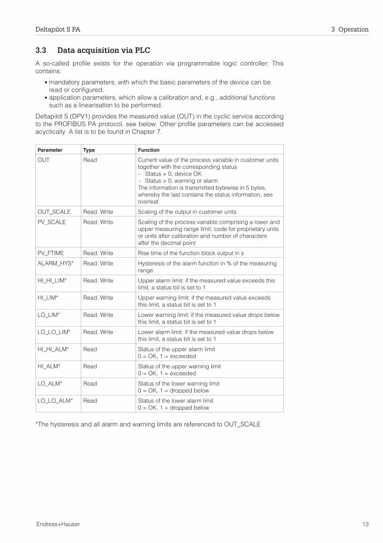
3.3 Data acquisition via PLC
A so-called profile exists for the operation via programmable logic controller: Thiscontains:
• mandatory parameters, with which the basic parameters of the device can beread or configured.
• application parameters, which allow a calibration and, e.g., additional functionssuch as a linearisation to be performed.
Deltapilot S (DPV1) provides the measured value (OUT) in the cyclic service accordingto the PROFIBUS PA protocol, see below. Other profile parameters can be accessedacyclically. A list is to be found in Chapter 7.
Parameter Type Function
OUT Read Current value of the process variable in customer unitstogether with the corresponding status– Status = 0, device OK– Status > 0, warning or alarmThe information is transmitted bytewise in 5 bytes,whereby the last contains the status information, seeoverleaf.
OUT_SCALE Read, Write Scaling of the output in customer units
PV_SCALE Read, Write Scaling of the process variable comprising a lower andupper measuring range limit, code for proprietary unitsor units after calibration and number of charactersafter the decimal point
PV_FTIME Read, Write Rise time of the function block output in s
ALARM_HYS* Read, Write Hysteresis of the alarm function in % of the measuringrange
HI_HI_LIM* Read, Write Upper alarm limit: if the measured value exceeds thislimit, a status bit is set to 1
HI_LIM* Read, Write Upper warning limit: if the measured value exceedsthis limit, a status bit is set to 1
LO_LIM* Read, Write Lower warning limit: if the measured value drops belowthis limit, a status bit is set to 1
LO_LO_LIM* Read, Write Lower alarm limit: if the measured value drops belowthis limit, a status bit is set to 1
HI_HI_ALM* Read Status of the upper alarm limit0 = OK, 1 = exceeded
HI_ALM* Read Status of the upper warning limit0 = OK, 1 = exceeded
LO_ALM* Read Status of the lower warning limit0 = OK, 1 = dropped below
LO_LO_ALM* Read Status of the lower alarm limit0 = OK, 1 = dropped below
*The hysteresis and all alarm and warning limits are referenced to OUT_SCALE
Deltapilot S PA 3 Operation
Endress+Hauser 13
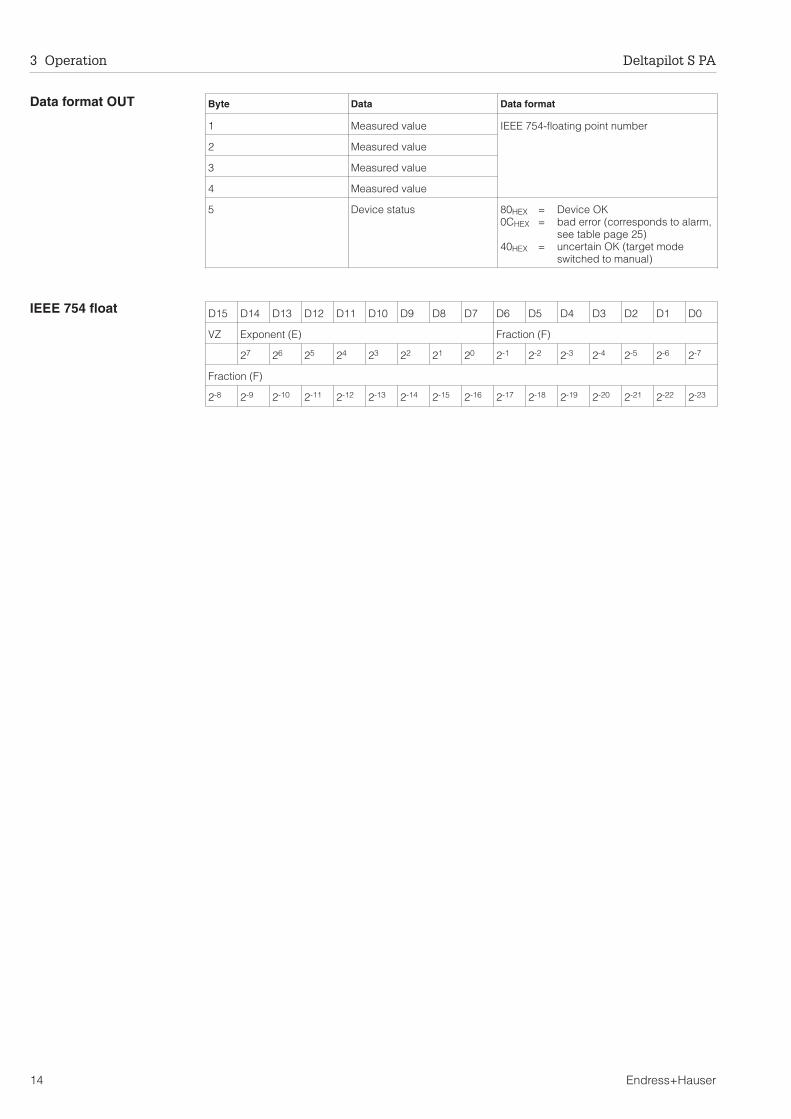
Data format OUT
IEEE 754 float D15 D14 D13 D12 D11 D10 D9 D8 D7 D6 D5 D4 D3 D2 D1 D0
VZ Exponent (E) Fraction (F)
27 26 25 24 23 22 21 20 2-1 2-2 2-3 2-4 2-5 2-6 2-7
Fraction (F)
2-8 2-9 2-10 2-11 2-12 2-13 2-14 2-15 2-16 2-17 2-18 2-19 2-20 2-21 2-22 2-23
Byte Data Data format
1 Measured value IEEE 754-floating point number
2 Measured value
3 Measured value
4 Measured value
5 Device status 80HEX = Device OK0CHEX = bad error (corresponds to alarm,
see table page 25)40HEX = uncertain OK (target mode
switched to manual)
3 Operation Deltapilot S PA
14 Endress+Hauser
4 Level Measurement
This chapter describes the parameters which must be entered to commission aDeltapilot S sensor with FEB 24 (P) electronic insert.
• Empty/full or dry calibration• Linearisation• Other settings• Locking the operating matrix• Measured value display
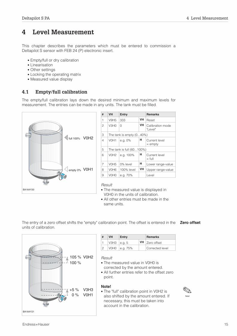
4.1 Empty/full calibration
The empty/full calibration lays down the desired minimum and maximum levels formeasurement. The entries can be made in any units. The tank must be filled.
# VH Entry Remarks
1 V9H5 333 VH Reset
2 V3H0 0 VH Calibration mode"Level"
3 The tank is empty (0...40%)
4 V0H1 e.g. 0% H Current level= empty
5 The tank is full (60...100%)
6 V0H2 e.g. 100% H Current level= full
7 V0H5 0% level H Lower range-value
8 V0H6 100% level VH Upper range-value
9 V0H0 e.g. 70% Level
Result• The measured value is displayed in
V0H0 in the units of calibration.• All other entries must be made in the
same units.
Zero offsetThe entry of a zero offset shifts the "empty" calibration point. The offset is entered in theunits of calibration.
# VH Entry Remarks
1 V3H3 e.g. 5 VH Zero offset
2 V0H0 e.g. 75% Corrected level
Result• The measured value in V0H0 is
corrected by the amount entered.• All further entries refer to the offset zero
point.
Note!• The "full" calibration point in V0H2 is
also shifted by the amount entered. Ifnecessary, this must be taken intoaccount in the calibration.
V0H2
V0H1
BA164Y20
full 100%
empty 0%
V0H2
V3H3V0H10 %
105 %100 %
+5 %
BA164Y21
Note!
Deltapilot S PA 4 Level Measurement
Endress+Hauser 15

Density correction If the calibration has been made with water or the product changes at a later date, thecalibration values can be corrected by entering a density factor.
new densityDensity factor = current factor x ——————
old density
Determining the densityfactor
Example: A tank is filled with water and calibrated. The density of the water (old density)is 1 g/cm3. Later the tank will be used as a storage tank and be filled with the actualmedium to be measured. The new density is 1.2 g/cm3. V3H2 still contains the factorysetting 1 g/cm3, i.e. the current factor is 1 g/cm3.
1.2 g/cm3
Density factor = 1 g/cm3 x —————— = 1.2 g/cm 3
1 g/cm3
# VH Entry Remarks
1 V3H2 e.g. 1.2 VH Density factor
2 V0H0 e.g. 62.5 % Corrected level
Result• The measured value in V0H0 is divided
by the density factor and is thus correctfor the new product
Note!• The entry of a density factor directly affects the level measurement. If volume is to be
measured by entering a linearisation curve, make sure the curve entered takesaccount of the current density factor.
BA164Y22
Measurement withproduct ρ = 1.2
Calibration withwater ρ = 1.0
Note!
4 Level Measurement Deltapilot S PA
16 Endress+Hauser
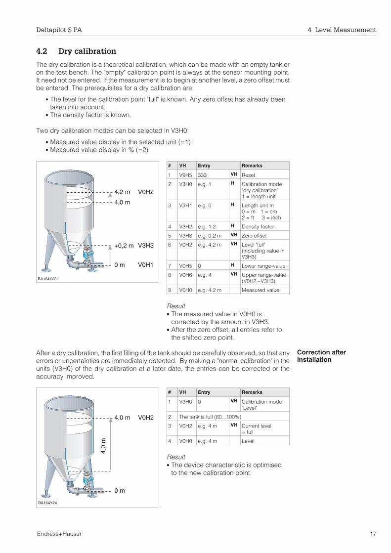
4.2 Dry calibration
The dry calibration is a theoretical calibration, which can be made with an empty tank oron the test bench. The "empty" calibration point is always at the sensor mounting point.It need not be entered. If the measurement is to begin at another level, a zero offset mustbe entered. The prerequisites for a dry calibration are:
• The level for the calibration point "full" is known. Any zero offset has already beentaken into account.
• The density factor is known.
Two dry calibration modes can be selected in V3H0:
• Measured value display in the selected unit (=1)• Measured value display in % (=2)
# VH Entry Remarks
1 V9H5 333 VH Reset
2 V3H0 e.g. 1 H Calibration mode"dry calibration"1 = length unit
3 V3H1 e.g. 0 H Length unit m0 = m 1 = cm2 = ft 3 = inch
4 V3H2 e.g. 1.2 H Density factor
5 V3H3 e.g. 0.2 m VH Zero offset
6 V0H2 e.g. 4.2 m VH Level "full"(including value inV3H3)
7 V0H5 0 H Lower range-value
8 V0H6 e.g. 4 VH Upper range-value(V0H2 – V3H3)
9 V0H0 e.g. 4.2 m Measured value
Result• The measured value in V0H0 is
corrected by the amount in V3H3.• After the zero offset, all entries refer to
the shifted zero point.
Correction afterinstallation
After a dry calibration, the first filling of the tank should be carefully observed, so that anyerrors or uncertainties are immediately detected. By making a "normal calibration" in theunits (V3H0) of the dry calibration at a later date, the entries can be corrected or theaccuracy improved.
# VH Entry Remarks
1 V3H0 0 VH Calibration mode"Level"
2 The tank is full (60...100%)
3 V0H2 e.g. 4 m VH Current level= full
4 V0H0 e.g. 4 m Level
Result• The device characteristic is optimised
to the new calibration point.
+0,2 m
4,0 m
4,2 m
0 m
V0H2
V3H3
V0H1
BA164Y23
4,0 m
4,0
m
0 m
V0H2
BA164Y24
Deltapilot S PA 4 Level Measurement
Endress+Hauser 17
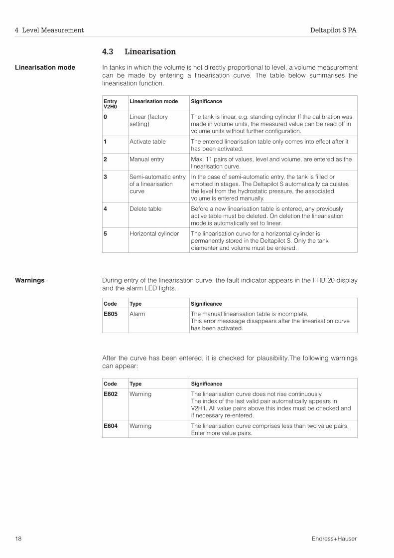
4.3 Linearisation
Linearisation mode In tanks in which the volume is not directly proportional to level, a volume measurementcan be made by entering a linearisation curve. The table below summarises thelinearisation function.
Warnings During entry of the linearisation curve, the fault indicator appears in the FHB 20 displayand the alarm LED lights.
After the curve has been entered, it is checked for plausibility.The following warningscan appear:
EntryV2H0
Linearisation mode Significance
0 Linear (factorysetting)
The tank is linear, e.g. standing cylinder If the calibration wasmade in volume units, the measured value can be read off involume units without further configuration.
1 Activate table The entered linearisation table only comes into effect after ithas been activated.
2 Manual entry Max. 11 pairs of values, level and volume, are entered as thelinearisation curve.
3 Semi-automatic entryof a linearisationcurve
In the case of semi-automatic entry, the tank is filled oremptied in stages. The Deltapilot S automatically calculatesthe level from the hydrostatic pressure, the associatedvolume is entered manually.
4 Delete table Before a new linearisation table is entered, any previouslyactive table must be deleted. On deletion the linearisationmode is automatically set to linear.
5 Horizontal cylinder The linearisation curve for a horizontal cylinder ispermanently stored in the Deltapilot S. Only the tankdiamenter and volume must be entered.
Code Type Significance
E605 Alarm The manual linearisation table is incomplete.This error messsage disappears after the linearisation curvehas been activated.
Code Type Significance
E602 Warning The linearisation curve does not rise continuously.The index of the last valid pair automatically appears inV2H1. All value pairs above this index must be checked andif necessary re-entered.
E604 Warning The linearisation curve comprises less than two value pairs.Enter more value pairs.
4 Level Measurement Deltapilot S PA
18 Endress+Hauser
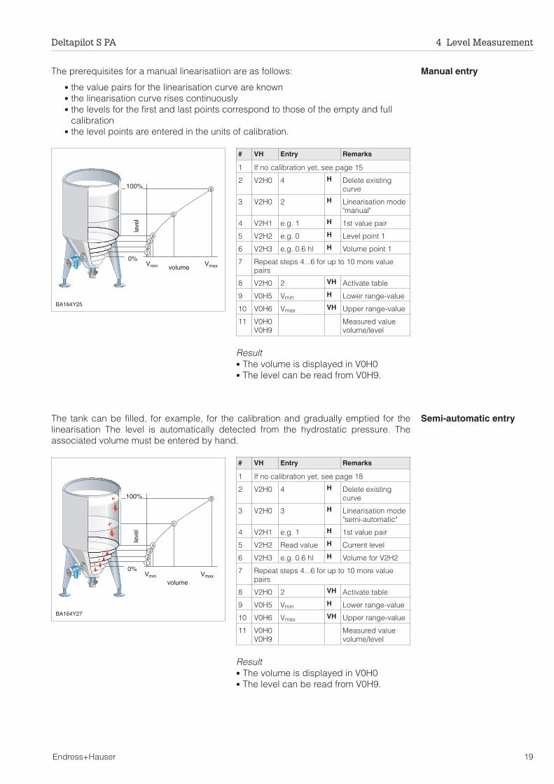
Manual entryThe prerequisites for a manual linearisatiion are as follows:
• the value pairs for the linearisation curve are known• the linearisation curve rises continuously• the levels for the first and last points correspond to those of the empty and full
calibration• the level points are entered in the units of calibration.
# VH Entry Remarks
1 If no calibration yet, see page 15
2 V2H0 4 H Delete existingcurve
3 V2H0 2 H Linearisation mode"manual"
4 V2H1 e.g. 1 H 1st value pair
5 V2H2 e.g. 0 H Level point 1
6 V2H3 e.g. 0.6 hl H Volume point 1
7 Repeat steps 4...6 for up to 10 more valuepairs
8 V2H0 2 VH Activate table
9 V0H5 Vmin H Lower range-value
10 V0H6 Vmax VH Upper range-value
11 V0H0V0H9
Measured valuevolume/level
Result• The volume is displayed in V0H0• The level can be read from V0H9.
Semi-automatic entryThe tank can be filled, for example, for the calibration and gradually emptied for thelinearisation The level is automatically detected from the hydrostatic pressure. Theassociated volume must be entered by hand.
# VH Entry Remarks
1 If no calibration yet, see page 18
2 V2H0 4 H Delete existingcurve
3 V2H0 3 H Linearisation mode"semi-automatic"
4 V2H1 e.g. 1 H 1st value pair
5 V2H2 Read value H Current level
6 V2H3 e.g. 0.6 hl H Volume for V2H2
7 Repeat steps 4...6 for up to 10 more valuepairs
8 V2H0 2 VH Activate table
9 V0H5 Vmin H Lower range-value
10 V0H6 Vmax VH Upper range-value
11 V0H0V0H9
Measured valuevolume/level
Result• The volume is displayed in V0H0• The level can be read from V0H9.
123
4
5
6
BA164Y25
0%
100%
volume
leve
l
Vmin Vmax
1
4
6
5
32
BA164Y27
0%
leve
l
100%
volumeVmin Vmax
Deltapilot S PA 4 Level Measurement
Endress+Hauser 19

Horizontal cylinder The permanently stored linearisation curve for a horizontal cylinder is activated byentering the following parameters:
• Tank diameter D in the units of calibration (V0H1/V0H2)• Tank volume V or weight in the units of linearisation
# VH Entry Remarks
1 If no calibration yet, see page 15
2 V2H0 4 H Delete existingcurve
3 V2H0 5 H Linearisation mode"horizontal cylinder"
4 V2H4 D H Tank diameter
5 V2H5 V H Tank volume
6 V2H3 e.g. 0.6 hl H Volume point 1
9 V0H5 0 H Lower range-value
10 V0H6 V VH Upper range-value
11 V0H0V0H9
Measured valuevolume/level
Result• The volume is displayed in V0H0• The level can be read from V0H9.
4.4 Other settings
Output damping τ The output damping influences the time it takes for the displays in V0H0, V0H8 and V0H9to react to a change in level. By increasing the output damping, the effect of a turbulentproduct surface on the measured value and maximum pointer displays can be damped,for example.
# VH Entry Remarks
1 V0H4 e.g. 30 H Output damping(0...99 s)
Signal on alarm On an alarm, an error code is transmitted with the measured value. The display andbargraph assume the selected value.
# VH Entry Remarks
1 V0H7 e.g. 0 VH Measured value onalarm0 = –199991 = +199992 = last value
D V
BA164Y26
BA164Y28
63%
level
signal
τtime
t
-19999
+19999
BA164Y29
Alarm
V0H7 = 1 (+19999)
V0H7 = 2 (hold value)
V0H7 = 0 (–19999)
4 Level Measurement Deltapilot S PA
20 Endress+Hauser

4.5 Locking/unlocking the matrix
After all parameters have been entered, the matrix can be locked
• via the keys on the operating and display module FHB 20 or• via the matrix by entering a three digit code ≠ 333 or 9303 in V9H9.
(333 or 9303 is the code for unlocking the matrix)
This protects the measuring point from accidental and unauthorised entries.
# VH Entry Remarks
Lock
1 V9H9 e.g. 100 VH Matrix locked(except V9H9)
Unlock
2 V9H9 333 VH Matrix unlocked
The table summarises the locking function
V
V
H
H
P---
F---
V+
– HBA164Y30
Lockingpress "+" and "V"simultaneously
UnlockingPress "– and "H"simultaneously
display ca. 2 s
display ca. 2 s
Fig. 4.1Locking and unlocking the matrix using the FHB 20
Locking via Display/readingof parameters
Changing/Writing via Unlocking via
keys communication keys communication
Keys yes no no yes no
Communication yes no no yes yes
Deltapilot S PA 4 Level Measurement
Endress+Hauser 21
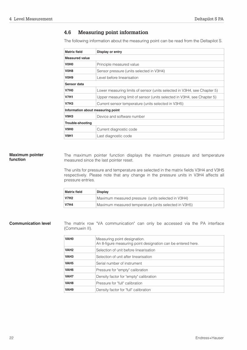
4.6 Measuring point information
The following information about the measuring point can be read from the Deltapilot S.
Maximum pointerfunction
The maximum pointer function displays the maximum pressure and temperaturemeasured since the last pointer reset.
The units for pressure and temperature are selected in the matrix fields V3H4 and V3H5respectively. Please note that any change in the pressure units in V3H4 affects allpressure entries.
Communication level The matrix row "VA communication" can only be accessed via the PA interface(Commuwin II).
Matrix field Display or entry
Measured value
V0H0 Principle measured value
V0H8 Sensor pressure (units selected in V3H4)
V0H9 Level before linearisation
Sensor data
V7H0 Lower measuring limits of sensor (units selected in V3H4, see Chapter 5)
V7H1 Upper measuring limit of sensor (units selected in V3H4, see Chapter 5)
V7H3 Current sensor temperature (units selected in V3H5)
Information about measuring point
V9H3 Device and software number
Trouble-shooting
V9H0 Current diagnostic code
V9H1 Last diagnostic code
Matrix field Display
V7H2 Maximum measured pressure (units selected in V3H4)
V7H4 Maximum measured temperature (units selected in V3H5)
VAH0 Measuring point designation.An 8-figure measuring point designation can be entered here.
VAH2 Selection of unit before linearisation
VAH3 Selection of unit after linearisation
VAH5 Serial number of instrument
VAH6 Pressure for "empty" calibration
VAH7 Density factor for "empty" calibration
VAH8 Pressure for "full" calibration
VAH9 Density factor for "full" calibration
4 Level Measurement Deltapilot S PA
22 Endress+Hauser

5 Pressure and Differential Pressure
In the calibration mode "pressure", the pressure acting on the Deltapilot S is displayedin V0H0. By using two Deltapilot S sensors, it is possible to measure the level inpressurised tanks or, for example, the differential pressure across a filter.
• In the pressure mode, the measuring range is that given on the sensor nameplate• Various pressure units can be selected in V3H4.
Pressure measurement,The Deltapilot S outputs a digital pressure signal in the units which have been set in V3H4.If necessary, the measured value is processed by the PLC.
# VH Entry Remarks
1 V9H5 333 VH Reset
2 V3H0 3 H Calibration mode"Pressure"
3 V3H4 e.g. 4 VH Pressure unit psisee Table
4 V0H5 e.g. 0 H Lower range-value
5 V0H6 e.g. 40 VH Upper range-value
6 V0H0 e.g. 15.5 Measured valuein e.g. psi
Pressure units in V3H4
No. Unit No. Unit No. Unit
0 mbar 6 in H2O 12 g / cm2
1 bar 7 Pa 13 kg / cm2
2 m H2O 8 MPa 14 lb / ft2
3 mm H2O 9 hPa 15 kgf / cm2
4 psi 10 mm Hg
5 ft H2O 11 in Hg
Note!• If the pressure unit is changed in V3H4, the electronic insert converts all values to
the new units. A new calibration is not necessary.• For other settings and locking of the matrix see section 4.4 or 4.5.
Mounting positionDepending upon the mounting position, it is possible that the sensor measures a differentpressure to that actually acting on it (for pressure measurements) or to that at thelower-range value (for level measurement). The difference can be entered as a correctionin V3H7. The corrected pressure is displayed in V0H8.
# VH Entry Text
1 V3H6 VH Sensor pressure
2 V3H7 e.g. 1 psi H Enter correction
3 V0H8 Corrected pressure
BA164Y31
Deltapilot S
processing inPLC
segmentcoupler
Note!
Deltapilot S PA 5 Pressure and Differential Pressure
Endress+Hauser 23
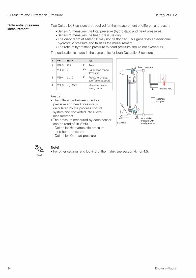
Differential pressureMeasurement
Two Deltapilot S sensors are required for the measurement of differential pressure.
• Sensor ➀ measures the total pressure (hydrostatic and head pressure).• Sensor ➁ measures the head pressure only.• The diaphragm of sensor ➁ may not be flooded. This generates an additional
hydrostatic pressure and falsifies the measurement.• The ratio of hydrostatic pressure to head pressure should not exceed 1:6.
The calibration is made in the same units for both Deltapilot S sensors.
# VH Entry Text
1 V9H5 333 VH Reset
2 V3H0 0 VH Calibration mode"Pressure"
3 V3H4 e.g. 0 VH Pressure unit barsee Table page 25
4 V0H0 e.g. 15.5 Measured valuein e.g. mbar
Result• The difference between the total
pressure and head pressure iscalculated by the process controlsystem and converted into a levelmeasurement.
• The pressure measured by each sensorcan be read off in V0H0– Deltapilot ➀: hydrostatic pressure
and head pressure;– Deltapilot ➁: head pressure
Note!• For other settings and locking of the matrix see section 4.4 or 4.5.
➀➀➀➀➀
➁
BA164Y32
head pressure
level via PLC
segmentcoupler
hydrostaticpressure withhead pressure
Note!
5 Pressure and Differential Pressure Deltapilot S PA
24 Endress+Hauser
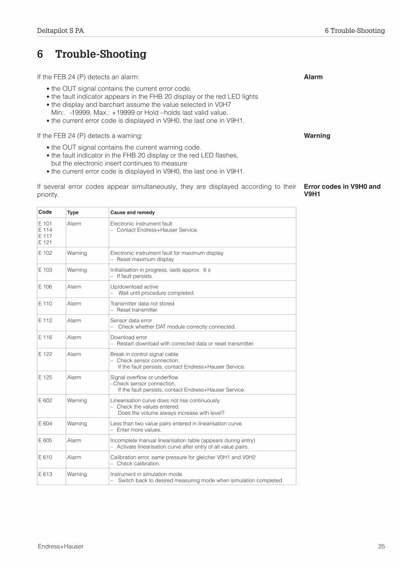
6 Trouble-Shooting
AlarmIf the FEB 24 (P) detects an alarm:
• the OUT signal contains the current error code.• the fault indicator appears in the FHB 20 display or the red LED lights• the display and barchart assume the value selected in V0H7
Min:. –19999, Max.: +19999 or Hold – holds last valid value.• the current error code is displayed in V9H0, the last one in V9H1.
WarningIf the FEB 24 (P) detects a warning:
• the OUT signal contains the current warning code.• the fault indicator in the FHB 20 display or the red LED flashes,
but the electronic insert continues to measure• the current error code is displayed in V9H0, the last one in V9H1.
Error codes in V9H0 andV9H1
If several error codes appear simultaneously, they are displayed according to theirpriority.
Code Type Cause and remedy
E 101E 114E 117E 121
Alarm Electronic instrument fault– Contact Endress+Hauser Service.
E 102 Warning Electronic instrument fault for maximum display– Reset maximum display
E 103 Warning Initialisation in progress, lasts approx. 6 s– If fault persists
E 106 Alarm Up/download active– Wait until procedure completed.
E 110 Alarm Transmitter data not stored– Reset transmitter.
E 112 Alarm Sensor data error– Check whether DAT module correctly connected.
E 116 Alarm Download error– Restart download with corrected data or reset transmitter.
E 122 Alarm Break in control signal cable– Check sensor connection.
If the fault persists, contact Endress+Hauser Service.
E 125 Alarm Signal overflow or underflow– Check sensor connection.
If the fault persists, contact Endress+Hauser Service.
E 602 Warning Linearisation curve does not rise continuously– Check the values entered.
Does the volume always increase with level?
E 604 Warning Less than two value pairs entered in linearisation curve.– Enter more values.
E 605 Alarm Incomplete manual linearisation table (appears during entry)– Activate linearisation curve after entry of all value pairs.
E 610 Alarm Calibration error, same pressure for gleicher V0H1 and V0H2– Check calibration.
E 613 Warning Instrument in simulation mode– Switch back to desired measuring mode when simulation completed.
Deltapilot S PA 6 Trouble-Shooting
Endress+Hauser 25
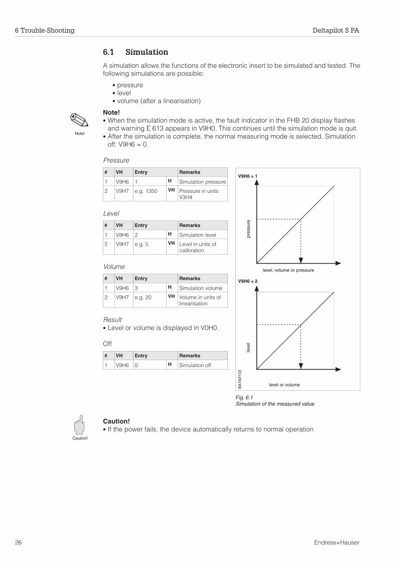
6.1 Simulation
A simulation allows the functions of the electronic insert to be simulated and tested. Thefollowing simulations are possible:
• pressure• level• volume (after a linearisation)
Note!• When the simulation mode is active, the fault indicator in the FHB 20 display flashes
and warning E 613 appears in V9H0. This continues until the simulation mode is quit.• After the simulation is complete, the normal measuring mode is selected. Simulation
off: V9H6 = 0.
Pressure
# VH Entry Remarks
1 V9H6 1 H Simulation pressure
2 V9H7 e.g. 1350 VH Pressure in unitsV3H4
Level
# VH Entry Remarks
1 V9H6 2 H Simulation level
2 V9H7 e.g. 5 VH Level in units ofcalibration
Volume
# VH Entry Remarks
1 V9H6 3 H Simulation volume
2 V9H7 e.g. 20 VH Volume in units oflinearisation
Result• Level or volume is displayed in V0H0.
Off
# VH Entry Remarks
1 V9H6 0 H Simulation off
Caution!• If the power fails, the device automatically returns to normal operation
Caution!
V9H6 = 1
level, volume or pressure
V9H6 = 2
BA
164Y
33
Fig. 6.1Simulation of the measured value
pres
sure
leve
l
level or volume
Note!
6 Trouble-Shooting Deltapilot S PA
26 Endress+Hauser
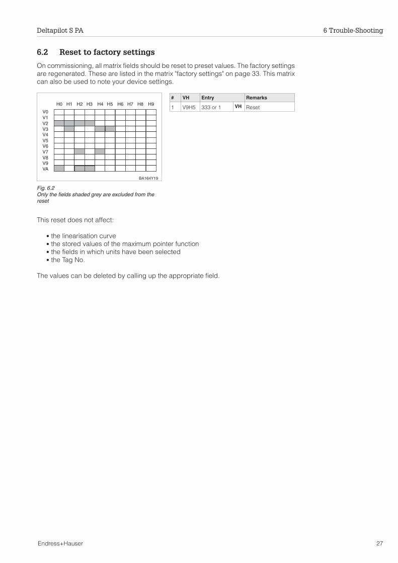
6.2 Reset to factory settings
On commissioning, all matrix fields should be reset to preset values. The factory settingsare regenerated. These are listed in the matrix "factory settings" on page 33. This matrixcan also be used to note your device settings.
# VH Entry Remarks
1 V9H5 333 or 1 VH Reset
This reset does not affect:
• the linearisation curve• the stored values of the maximum pointer function• the fields in which units have been selected• the Tag No.
The values can be deleted by calling up the appropriate field.
H0
V0V1V2V3V4V5V6V7V8V9VA
H1 H2 H3 H4 H5 H6 H7 H8 H9
BA164Y19
Fig. 6.2Only the fields shaded grey are excluded from thereset
Deltapilot S PA 6 Trouble-Shooting
Endress+Hauser 27
6.3 Exchange of the electronic insert or measuring cell
Electronic insert If the electronic insert has to be exchanged, all measuring cell data can be transferredto the replacement by simply installing the old DAT module.
• Instructions on the exchange are delivered with the new insert.• Installation and wiring is described in Section 2.2.• After the exchange, the calibration and other settings must be repeated.
Caution!• If the electronic insert is exchanged by the user, take care that the replacement
corresponds to that specified on the Deltapilot S nameplate.
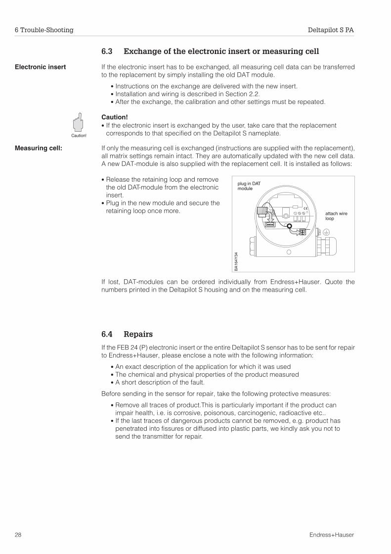
Measuring cell: If only the measuring cell is exchanged (instructions are supplied with the replacement),all matrix settings remain intact. They are automatically updated with the new cell data.A new DAT-module is also supplied with the replacement cell. It is installed as follows:
• Release the retaining loop and removethe old DAT-module from the electronicinsert.
• Plug in the new module and secure theretaining loop once more.
If lost, DAT-modules can be ordered individually from Endress+Hauser. Quote thenumbers printed in the Deltapilot S housing and on the measuring cell.
6.4 Repairs
If the FEB 24 (P) electronic insert or the entire Deltapilot S sensor has to be sent for repairto Endress+Hauser, please enclose a note with the following information:
• An exact description of the application for which it was used• The chemical and physical properties of the product measured• A short description of the fault.
Before sending in the sensor for repair, take the following protective measures:
• Remove all traces of product.This is particularly important if the product canimpair health, i.e. is corrosive, poisonous, carcinogenic, radioactive etc..
• If the last traces of dangerous products cannot be removed, e.g. product haspenetrated into fissures or diffused into plastic parts, we kindly ask you not tosend the transmitter for repair.
GREEN
BA
164Y
34
attach wireloop
plug in DATmodule
Caution!
6 Trouble-Shooting Deltapilot S PA
28 Endress+Hauser

7 PROFIBUS-PA Parameters
Parameter Matrix Index(Slot = 1)
Read Write Type Sizebytes
Directory object header 0 X OSTRING 12
Composite list directory entries 1 X OSTRING 24
Physical block block object 14 X OSTRING 20
PB Static revision 15 X UNSIGNED16 2
PB Device tag VAH0 16 X X OSTRING 32
PB Strategy 17 X X UNSIGNED16 2
PB Alert key 18 X X UNSIGNED8 1
PB Target mode 19 X X UNSIGNED8 1
PB Mode 20 X OSTRING 3
PB Alarm summary 21 X OSTRING 8
PB Software revision 22 X OSTRING 16
PB Hardware revision 23 X OSTRING 16
PB Device manufacturer identity 24 X UNSIGNED16 2
PB Device identity 25 X OSTRING 16
PB Device serial number 26 X OSTRING 16
PB Diagnosis 27 X OSTRING 4
PB Diagnosis extension 28 X OSTRING 6
PB Diagnosis mask 29 X OSTRING 4
PB Diagnosis extension mask 30 X OSTRING 6
PB Device certiffication 31 X X OSTRING 16
PB Security lock V9H9 32 X X UNSIGNED16 2
PB Factory reset V9H5 33 X UNSIGNED16 2
reserved 34 - 43
PB Descriptor 44 X X OSTRING 32
PB Device message 45 X X OSTRING 32
PB Device installation date 46 X X OSTRING 8
reserved 47 - 51
PB Matrix error code V9H0 52 X UNSIGNED16 2
PB Matrix last error code V9H1 53 X X UNSIGNED16 2
PB Device bus address V9H4 54 X UNSIGNED8 1
PB UpDown features supported 55 X OSTRING 1
PB UpDown control 56 X UNSIGNED8 1
PB UpDown parameter 57 X UPDOWN_PARAM 20
PB Device and software number V9H3 58 X UNSIGNED16 2
reserved 59 - 63
Transducer block block object 64 X OSTRING 20
TB Static revision 65 X UNSIGNED16 2
TB Device tag VAH0 66 X X OSTRING 32
TB Strategy 67 X X UNSIGNED16 2
TB Alert key 68 X X UNSIGNED8 1
TB Target mode 69 X X UNSIGNED8 1
TB Mode 70 X OSTRING 3
TB Alarm summary 71 X OSTRING 8
TB Volume V0H0 72 X FLOAT 4
TB Volume unit VAH3 73 X X UNSIGNED16 2
TB Sensor hi limit V7H1 74 X FLOAT 4
TB Sensor lo limit V7H0 75 X FLOAT 4
TB Level V0H9 76 X FLOAT 4
TB Level unit VAH2 77 X X UNSIGNED16 2
TB Sensor value V3H6 78 X FLOAT 4
TB Empty calibration V0H1 79 X X FLOAT 4
TB Full calibration V0H2 80 X X FLOAT 4
TB Zero offset V3H3 81 X X FLOAT 4
TB Operating mode V3H0 82 X X UNSIGNED8 1
TB Temperature V7H3 83 X FLOAT 4
TB Temperature unit V3H5 84 X X UNSIGNED16 2
TB Max. temperature V7H4 85 X X FLOAT 4
reserved 86 - 93
Deltapilot S PA 7 PROFIBUS-PA Parameters
Endress+Hauser 29
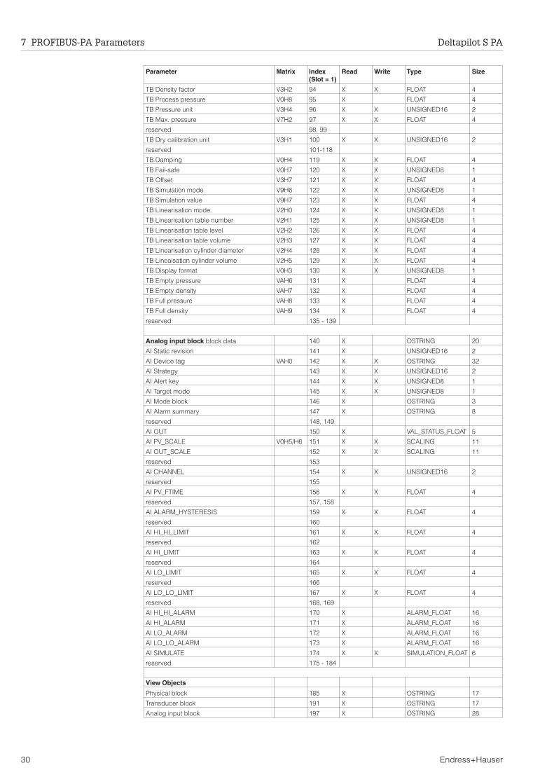
Parameter Matrix Index(Slot = 1)
Read Write Type Size
TB Density factor V3H2 94 X X FLOAT 4
TB Process pressure V0H8 95 X FLOAT 4
TB Pressure unit V3H4 96 X X UNSIGNED16 2
TB Max. pressure V7H2 97 X X FLOAT 4
reserved 98, 99
TB Dry calibration unit V3H1 100 X X UNSIGNED16 2
reserved 101-118
TB Damping V0H4 119 X X FLOAT 4
TB Fail-safe V0H7 120 X X UNSIGNED8 1
TB Offset V3H7 121 X X FLOAT 4
TB Simulation mode V9H6 122 X X UNSIGNED8 1
TB Simulation value V9H7 123 X X FLOAT 4
TB Linearisation mode V2H0 124 X X UNSIGNED8 1
TB Linearisatiion table number V2H1 125 X X UNSIGNED8 1
TB Linearisation table level V2H2 126 X X FLOAT 4
TB Linearisation table volume V2H3 127 X X FLOAT 4
TB Linearisation cylinder diameter V2H4 128 X X FLOAT 4
TB Lineaisation cylinder volume V2H5 129 X X FLOAT 4
TB Display format V0H3 130 X X UNSIGNED8 1
TB Empty pressure VAH6 131 X FLOAT 4
TB Empty density VAH7 132 X FLOAT 4
TB Full pressure VAH8 133 X FLOAT 4
TB Full density VAH9 134 X FLOAT 4
reserved 135 - 139
Analog input block block data 140 X OSTRING 20
AI Static revision 141 X UNSIGNED16 2
AI Device tag VAH0 142 X X OSTRING 32
AI Strategy 143 X X UNSIGNED16 2
AI Alert key 144 X X UNSIGNED8 1
AI Target mode 145 X X UNSIGNED8 1
AI Mode block 146 X OSTRING 3
AI Alarm summary 147 X OSTRING 8
reserved 148, 149
AI OUT 150 X VAL_STATUS_FLOAT 5
AI PV_SCALE V0H5/H6 151 X X SCALING 11
AI OUT_SCALE 152 X X SCALING 11
reserved 153
AI CHANNEL 154 X X UNSIGNED16 2
reserved 155
AI PV_FTIME 156 X X FLOAT 4
reserved 157, 158
AI ALARM_HYSTERESIS 159 X X FLOAT 4
reserved 160
AI HI_HI_LIMIT 161 X X FLOAT 4
reserved 162
AI HI_LIMIT 163 X X FLOAT 4
reserved 164
AI LO_LIMIT 165 X X FLOAT 4
reserved 166
AI LO_LO_LIMIT 167 X X FLOAT 4
reserved 168, 169
AI HI_HI_ALARM 170 X ALARM_FLOAT 16
AI HI_ALARM 171 X ALARM_FLOAT 16
AI LO_ALARM 172 X ALARM_FLOAT 16
AI LO_LO_ALARM 173 X ALARM_FLOAT 16
AI SIMULATE 174 X X SIMULATION_FLOAT 6
reserved 175 - 184
View Objects
Physical block 185 X OSTRING 17
Transducer block 191 X OSTRING 17
Analog input block 197 X OSTRING 28
7 PROFIBUS-PA Parameters Deltapilot S PA
30 Endress+Hauser
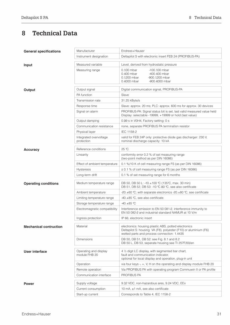
8 Technical Data
General specifications Manufacturer Endress+Hauser
Instrument designation Deltapilot S with electronic insert FEB 24 (PROFIBUS-PA)
Input Measured variable Level, derived from hydrostatic pressure
Measuring range 0…100 mbar –100…100 mbar0…400 mbar –400…400 mbar0…1200 mbar –900…1200 mbar0…4000 mbar –900…4000 mbar
Output Output signal Digital communication signal, PROFIBUS-PA
PA function Slave
Transmission rate 31.25 kByte/s
Response time Slave: approx. 20 ms; PLC: approx. 600 ms for approx. 30 devices
Signal on alarm PROFIBUS-PA: Signal status bit is set, last valid measured value heldDisplay: selectable -19999, +19999 or hold (last value)
Output damping 0…99 s in V0H4, Factory setting: 0 s
Communication resistance none, separate PROFIBUS PA termination resistor
Physical layer IEC 1158-2
Integrated overvoltageprotection
valid for FEB 24P only: protective diode gas discharger: 230 V,nominal discharge capacity: 10 kA
Accuracy Reference conditions 25 °C
Linearity conformity error 0.2 % of set measuring range(two-point method as per DIN 16086)
Effect of ambient temperature 0.1 %/10 K of cell measuring range FS (as per DIN 16086)
Hysteresis ± 0.1 % of cell measuring range FS (as per DIN 16086)
Long-term drift 0.1 % of set measuring range for 6 months
Operating conditions Medium temperature range DB 50, DB 50 L: –10…+100 °C (135°C, max. 30 min)DB 51, DB 52, DB 53: –10 °C…80 °C, see also certificate
Ambient temperature –20…+60 °C; with separate electronics –20…+80 °C, see certificate
Limiting temperature range –40…+85 °C, see also certificate
Storage temperature range –40…+85 °C
Electromagnetic compatibility Interference emission to EN 50 081–2, interference immunity toEN 50 082–2 and industrial standard NAMUR at 10 V/m
Ingress protection IP 66, electronic insert
Mechanical contruction Material electronics: housing plastic ABS, potted electronicsDeltapilot S: housing VA (F8), polyester (F10) or aluminium (F6)wetted parts and process connection: 1.4435
Dimensions DB 50, DB 51, DB 52: see Fig. 8.1 and 8.2DB 50 L, DB 53, separate housing see TI 257F/00/en
User interface Operating and displaymodule FHB 20
4 ½ digit LC display, with segmented bar chart,fault and communication indicator,optional for local display and operation, plug-in unit
Operation via four keys –, +, V, H on the operating and display module FHB 20
Remote operation Via PROFIBUS PA with operating program Commuwin II or PA profile
Communication interface PROFIBUS PA
Power Supply voltage 9…32 VDC, non-hazardous ares, 9…24 VDC, EEx
Current consumption 10 mA, ±1 mA, see also certificate
Start-up current Corresponds to Table 4, IEC 1158-2
Deltapilot S PA 8 Technical Data
Endress+Hauser 31
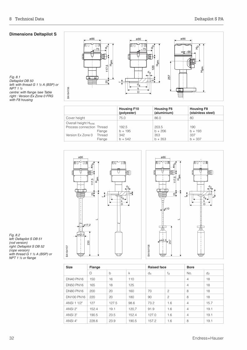
Dimensions Deltapilot S
120
d4
d2
kD
117,
5
ø86 ø86
HD
HD
Hge
s.
Hge
s.
~75 ~75
25 f b 257
HD
ø86
~66
Hge
s.
BA
164Y
06
Fig. 8.1Deltapilot DB 50left: with thread G 1 ½ A (BSP) orNPT 1 ½centre: with flange /see Tableright : Version Ex Zone 0 FRGwith F8 housing
ø17,2
ø42,5
L
230
117,
5
ø86
~75
25
d4
d2
kD
f
b
HD
Hge
s.
BA
164Y
07
Fig. 8.2left: Deltapilot S DB 51(rod version)right: Deltapilot S DB 52(rope version)with thread G 1 ½ A (BSP) orNPT 1 ½ or flange
ø42,5
257
25
L
117,
5
ø86
~75
ø10
d4
d2
kD
f b
HD
Hge
s.
BA
164Y
08
Housing F10(polyester)
Housing F6(aluminium)
Housing F8(stainless steel)
Cover height 75.0 86.0 80
Overall height Htotal.
Process connection ThreadFlange
Version Ex Zone 0 ThreadFlange
192.5b + 195342b + 542
203.5b + 206353b + 353
190b + 193337b + 337
Size Flange Raised face Bore
D b k d4 fd No. d2
DN40 PN16 150 16 110 4 18
DN50 PN16 165 18 125 4 18
DN80 PN16 200 20 160 70 2 8 18
DN100 PN16 220 20 180 90 2 8 18
ANSI 1 1/2" 127 127.5 98.6 73.2 1.6 4 15.7
ANSI 2" 152.4 19.1 120,7 91.9 1.6 4 19.1
ANSI 3" 190.5 23.5 152.4 127.0 1.6 4 19.1
ANSI 4" 228.6 23.9 190.5 157.2 1.6 8 19.1
8 Technical Data Deltapilot S PA
32 Endress+Hauser
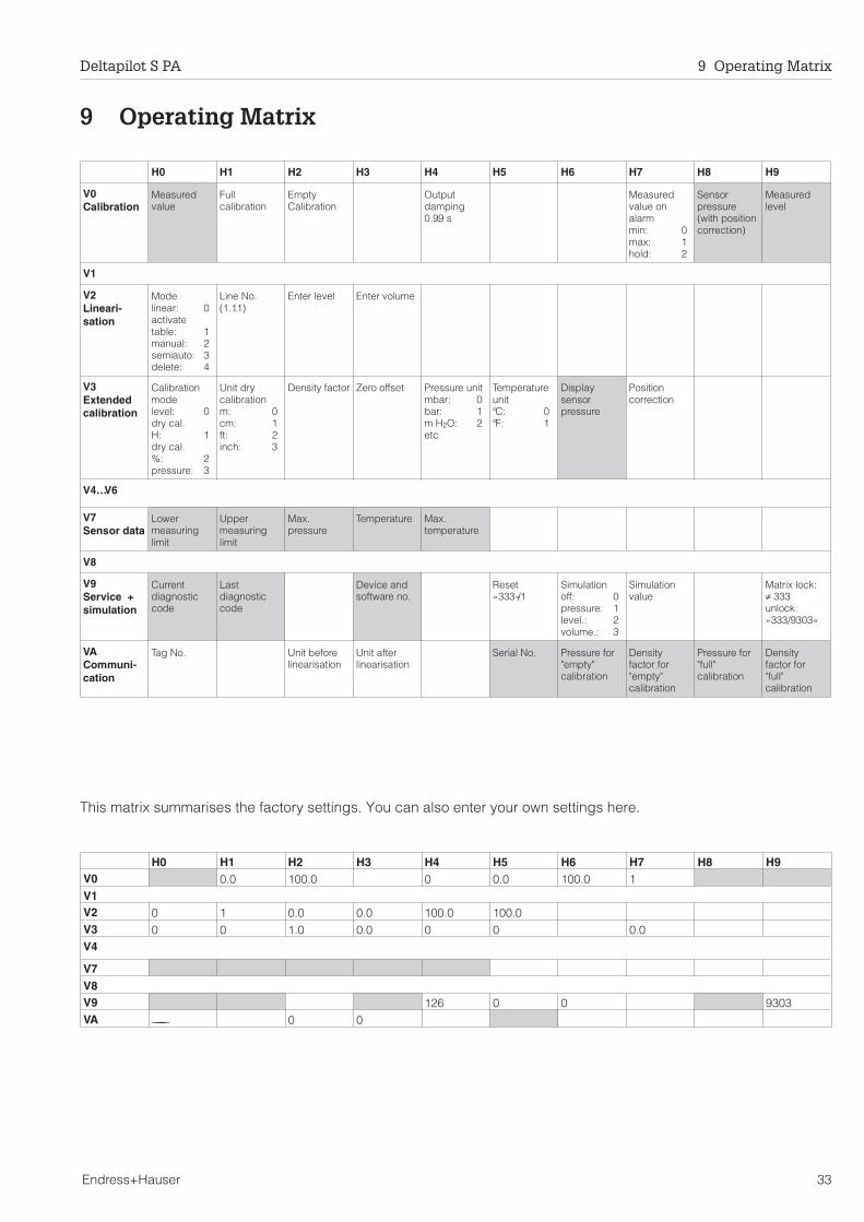
9 Operating Matrix
This matrix summarises the factory settings. You can also enter your own settings here.
H0 H1 H2 H3 H4 H5 H6 H7 H8 H9
V0Calibration
Measuredvalue
Fullcalibration
EmptyCalibration
Outputdamping0…99 s
Measuredvalue onalarmmin: 0max: 1hold: 2
Sensorpressure(with positioncorrection)
Measuredlevel
V1
V2Lineari-sation
Modelinear: 0activatetable: 1manual: 2semiauto: 3delete: 4
Line No.(1…11)
Enter level Enter volume
V3Extendedcalibration
Calibrationmodelevel: 0dry cal.H: 1dry cal.%: 2pressure: 3
Unit drycalibrationm: 0cm: 1ft: 2inch: 3
Density factor Zero offset Pressure unitmbar: 0bar: 1m H2O: 2etc
Temperatureunit°C: 0°F: 1
Displaysensorpressure
Positioncorrection
V4… V6
V7Sensor data
Lowermeasuringlimit
Uppermeasuringlimit
Max.pressure
Temperature Max.temperature
V8
V9Service +simulation
Currentdiagnosticcode
Lastdiagnosticcode
Device andsoftware no.
Reset»333«/1
Simulationoff: 0pressure: 1level.: 2volume.: 3
Simulationvalue
Matrix lock:≠ 333unlock:»333/9303«
VACommuni-cation
Tag No. Unit beforelinearisation
Unit afterlinearisation
Serial No. Pressure for"empty"calibration
Densityfactor for"empty"calibration
Pressure for"full"calibration
Densityfactor for"full"calibration
H0 H1 H2 H3 H4 H5 H6 H7 H8 H9V0 0.0 100.0 0 0.0 100.0 1V1V2 0 1 0.0 0.0 100.0 100.0V3 0 0 1.0 0.0 0 0 0.0V4
V7V8V9 126 0 0 9303VA ———- 0 0
Deltapilot S PA 9 Operating Matrix
Endress+Hauser 33
Index
AAlarm . . . . . . . . . . . . . . . . . . . 20, 25Application . . . . . . . . . . . . . . . . . . . 5Approved usage . . . . . . . . . . . . . . . . 3
BBus address . . . . . . . . . . . . . . . . . . 9Bus cable . . . . . . . . . . . . . . . . . . . 9Bus coupler . . . . . . . . . . . . . . . . . . 6
CCable entry . . . . . . . . . . . . . . . . . . 8Calibration . . . . . . . . . . . . . . . . . . . 15Certificates . . . . . . . . . . . . . . . . . . . 3Communication . . . . . . . . . . . . . . . . . 22Commuwin II . . . . . . . . . . . . . . . . . . 12Compact version . . . . . . . . . . . . . . . . 7Connection . . . . . . . . . . . . . . . . . . . 9
DDAT-module . . . . . . . . . . . . . . . . . . 28Density factor . . . . . . . . . . . . . . . . . . 16Device parameter file . . . . . . . . . . . . . . . 10Differential pressure measurement . . . . . . . . . 24
EElectronic insert FEB 24 P . . . . . . . . . . . . 5, 28Error codes . . . . . . . . . . . . . . . . . . 25Exchanging components . . . . . . . . . . . . . 28Explosion protection . . . . . . . . . . . . . . . 3
FFactory settings . . . . . . . . . . . . . . . . . 33
HHousing adapter . . . . . . . . . . . . . . . . 8
IInstallation . . . . . . . . . . . . . . . . . . 7 - 10Installation hints . . . . . . . . . . . . . . . . . 7
LLevel measurement . . . . . . . . . . . . . 15 - 22Linearisation . . . . . . . . . . . . . . . . 16, 18Locking the matrix . . . . . . . . . . . . . . . . 21
MMaximum pointer . . . . . . . . . . . . . . . . 22Measured value . . . . . . . . . . . . . . . . . 22Measuring point information . . . . . . . . . . . . 22Measuring system . . . . . . . . . . . . . . . . 6
NNo. of transmitters . . . . . . . . . . . . . . . . 6Notes on Safety . . . . . . . . . . . . . . . . . 3
OOperating and display module FHB 20 . . . . . . . 9, 11Operating matrix . . . . . . . . . . . . . . . 11, 33Operating principle . . . . . . . . . . . . . . . . 5Operating program Commuwin II . . . . . . . . . . 6Operation via PLC . . . . . . . . . . . . . . . . 13Output damping . . . . . . . . . . . . . . . . . 20
PPressure measurement . . . . . . . . . . . . . . 23Process diaphragm . . . . . . . . . . . . . . . 7PROFIBUS-PA-Parameter . . . . . . . . . . . 29 - 30
RRemote operation . . . . . . . . . . . . . . . . 12Repairs . . . . . . . . . . . . . . . . . . . . 28Rod version . . . . . . . . . . . . . . . . . . 5, 7Rope version . . . . . . . . . . . . . . . . . 5, 7
SSealing . . . . . . . . . . . . . . . . . . . . 8Semi-automatic linearisatiion . . . . . . . . . . . . 19Sensor housing . . . . . . . . . . . . . . . . . 8Sensor data . . . . . . . . . . . . . . . . . . . 22Simulation . . . . . . . . . . . . . . . . . . . 26
TTechnical data . . . . . . . . . . . . . . . . 31 - 32Terminating resistor . . . . . . . . . . . . . . . 6Trouble-Shooting . . . . . . . . . . . . . . . 25 - 28
UUnlocking the matrix . . . . . . . . . . . . . . . 21
WWarning . . . . . . . . . . . . . . . . . . . . 25
ZZero offset . . . . . . . . . . . . . . . . . . . 17
Deltapilot S PA Index
34

Europe
Austria Endress+Hauser Ges.m.b.H.WienTel. (01) 880 56-0, Fax (01) 88056-35
BelarusBelorgsintezMinskTel. (01 72) 26 31 66, Fax (0172) 263111
Belgium / Luxembourg Endress+Hauser S.A./N.V.BrusselsTel. (02) 248 0600, Fax (02) 24805 53
BulgariaINTERTECH-AUTOMATIONSofiaTel. (02) 6528 09, Fax (02) 6528 09
Croatia Endress+Hauser GmbH+Co.ZagrebTel. (01) 660 1418, Fax (01) 66014 18
CyprusI+G Electrical Services Co. Ltd.NicosiaTel. (02) 4847 88, Fax (02) 4846 90
Czech Republic Endress+Hauser GmbH+Co.PrahaTel. (0 26) 6 7842 00, Fax (0 26) 67841 79
Denmark Endress+Hauser A/SSøborgTel. (31) 6731 22, Fax (31) 6730 45
EstoniaElvi-AquaTartuTel. (7) 4227 26, Fax (7) 42 2727
Finland Endress+Hauser OyEspooTel. (90) 859 6155, Fax (90) 85960 55
France Endress+HauserHuningueTel. 896967 68, Fax 8969 4802
Germany Endress+Hauser Meßtechnik GmbH+Co.Weil am RheinTel. (0 7621) 975-01, Fax (0 7621) 975-5 55
Great Britain Endress+Hauser Ltd.ManchesterTel. (01 61) 2 865000, Fax (01 61) 9 981841
GreeceI & G Building Services Automation S.A.AthensTel. (01) 924 1500, Fax (01) 92217 14
HungaryMile Ipari-ElektroBudapestTel. (01) 261 5535, Fax (01) 26155 35
IcelandVatnshreinsun HFReykjavikTel. (05) 8896 16, Fax (05) 8896 13
IrelandFlomeaco Company Ltd.KildareTel. (0 45) 86 8615, Fax (045) 8681 82
Italy Endress+Hauser Italia S.p.A.Cernusco s/N MilanoTel. (02) 9210 64 21, Fax (02) 92 107153
JugoslaviaMeris d.o.o.BeogradTel. (11) 444 2966, Fax (11) 43 0043
LatviaRaita Ltd.RigaTel. (02) 2547 95, Fax (02) 7 25 8933
LithuaniaAgava Ltd.KaunasTel. (07) 2024 10, Fax (07) 2074 14
Netherland Endress+Hauser B.V.NaardenTel. (0 35) 6 958611, Fax (0 35) 6 9588 25
Norway Endress+Hauser A/STranbyTel. (0 32) 85 10 85, Fax (032) 8511 12
Poland Endress+Hauser Polska Sp. z o.o.WarszawyTel. (0 22) 7 201090, Fax (0 22) 7 2010 85
PortugalTecnisis - Tecnica de Sistemas IndustriaisLinda-a-VelhaTel. (01) 417 26 37, Fax (01) 4 1852 78
RomaniaRomconseng SRLBucharestTel. (01) 410 16 34, Fax (01) 4 1016 34
Russia Endress+Hauser Moscow OfficeMoscowTel., Fax: see Endress+Hauser GmbH+Co.Instruments International
Slovak RepublicTranscom Technik s.r.o.BratislavaTel. (7) 521 3161, Fax (7) 521 31 81
Slovenia Endress+Hauser D.O.O.LjubljanaTel. (0 61) 1 592217, Fax (0 61) 1 5922 98
Spain Endress+Hauser S.A.BarcelonaTel. (93) 480 33 66, Fax (93) 4 7338 39
Sweden Endress+Hauser ABSollentunaTel. (08) 626 16 00, Fax (08) 6 2694 77
Switzerland Endress+Hauser AGReinach/BL 1Tel. (0 61) 7 156222, Fax (0 61) 7 1116 50
TurkeyIntek Endüstriyel Ölcü ve Kontrol SistemleriIstanbulTel. (0212) 2 75 1355, Fax (0212) 2 66 2775
UkraineIndustria UkraïnaKievTel. (44) 268 52 13, Fax (44) 2 6852 13
Africa
EgyptAnasiaHeliopolis/CairoTel. (02) 417 90 07, Fax (02) 4 1790 08
MoroccoOussama S.A.CasablancaTel. (02) 241338, Fax (02) 4026 57
NigeriaJ F Technical Invest. Nig. Ltd.LagosTel. (1) 6223 45 46, Fax (1) 62 2345 48
South Africa Endress+Hauser Pty. Ltd.SandtonTel. (0 11) 4 441386, Fax (0 11) 4 4419 77
TunisiaControle, Maintenance et RegulationTunisTel. (01) 793077, Fax (01) 7885 95
America
Argentina Endress+Hauser Argentina S.A.Buenos AiresTel. (01) 523 80 08, Fax (01) 5 2205 46
BoliviaTritec S.R.L.CochabambaTel. (0 42) 5 6993, Fax (042) 5 09 81
Brazil Samson Endress+Hauser Ltda.Sao PauloTel. (011) 5 36 3455, Fax (0 11) 5 363067
Canada Endress+Hauser Ltd.Burlington, OntarioTel. (905) 6 81 9292, Fax (9 05) 6 819444
ChileDIN Instrumentos Ltda.SantiagoTel. (02) 20501 00, Fax (02) 2 258139
ColombiaColsein Ltd.Bogota D.C.Tel. (01) 23676 59, Fax (01) 6 107868
Costa RicaEURO-TEC S.A.San JoseTel. 2 9615 42, Fax 296 1542
EcuadorInsetec Cia. Ltda.QuitoTel. (02) 25 1242, Fax (02) 461833
GuatemalaACISA Automatizacion Y Control Industrial S.A.Ciudad de Guatemala, C.A.Tel. (02) 34 5985, Fax (02) 327431
Mexico Endress+Hauser I.I.Mexico CityTel. (5) 568 96 58, Fax (5) 56841 83
ParaguayIncoel S.R.L.AsuncionTel. (021) 2139 89, Fax (021) 265 83
UruguayCircular S.A.MontevideoTel. (02) 92 5785, Fax (02) 929151
USA Endress+Hauser Inc.Greenwood, IndianaTel. (317) 5 35-7138, Fax (317) 5 35-1489
VenezuelaH. Z. Instrumentos C.A.CaracasTel. (02) 97988 13, Fax (02) 9 799608
Asia
China Endress+Hauser Shanghai
Instrumentation Co. Ltd.ShanghaiTel. (021) 6464 6700, Fax (021) 6474 7860
Endress+Hauser Beijing OfficeBeijingTel. (010) 6834 4058, Fax: (0 10) 68 344068
Hong Kong Endress+Hauser (H.K.) Ltd.Hong KongTel. 25 283120, Fax 286541 71
India Endress+Hauser India Branch OfficeMumbaiTel. (022) 6 04 5578, Fax (0 22) 6 040211
IndonesiaPT Grama BazitaJakartaTel. (21) 79750 83, Fax (21) 7 975089
Japan Sakura Endress Co., Ltd.TokyoTel. (0422) 5406 11, Fax (04 22) 55 0275
Malaysia Endress+Hauser (M) Sdn. Bhd.Petaling Jaya, Selangor Darul EhsanTel. (03) 73348 48, Fax (03) 7 338800
PakistanSpeedy AutomationKarachiTel. (021) 7 72 2953, Fax (0 21) 7 736884
Papua-NeuguineaSBS Electrical Pty LimitedPort MoresbyTel. 53 251188, Fax 532595 56
PhilippinesBrenton Industries Inc.Makati Metro ManilaTel. (2) 84306 61-5, Fax (2) 817 57 39
Singapore Endress+Hauser (S.E.A.) Pte., Ltd.SingaporeTel. 4 688222, Fax 466 68 48
South Korea Endress+Hauser (Korea) Co., Ltd.SeoulTel. (02) 6 5872 00, Fax (02) 6 59 2838
TaiwanKingjarl CorporationTaipei R.O.C.Tel. (02) 7 1839 38, Fax (02) 7 13 4190
Thailand Endress+Hauser Ltd.BangkokTel. (2) 99678 11-20, Fax (2) 99678 10
VietnamTan Viet Bao Co. Ltd.Ho Chi Minh CityTel. (08) 8 3352 25, Fax (08) 8 33 5227
IranTelephone Technical Services Co. Ltd.TehranTel. (021) 874 6750, Fax(0 21) 87372 95
IsraelInstrumetrics Industrial Control Ltd.Tel-AvivTel. (03) 6 4802 05, Fax (03) 6 47 1992
JordanA.P. Parpas Engineering S.A.AmmanTel. (06) 5 5392 83, Fax (06) 5 53 9205
Kingdom of Saudi ArabiaAnasiaJeddahTel. (02) 6 7100 14, Fax (02) 6 72 5929
KuwaitKuwait Maritime & Mercantile Co. K.S.C.SafatTel. 2 434752, Fax 244 14 86
LebanonNabil IbrahimJbeilTel. (3) 25 4051, Fax (9) 9440 80
Sultanate of OmanMustafa & Jawad Sience & Industry Co.L.L.C.RuwiTel. 60 20 09, Fax 60 70 66
United Arab EmiratesDescon Trading EST.DubaiTel. (04) 35 9522, Fax (04) 35 9617
YemenYemen Company for Ghee and Soap IndustryTaizTel. (04) 23 0664, Fax (04) 21 2338
Australia + New Zealand
AustraliaGEC Alsthom LTD.SydneyTel. (02) 96 450777, Fax (02) 9743 70 35
New ZealandEMC Industrial InstrumentationAucklandTel. (09) 4 4492 29, Fax (09) 4 44 1145
All other countries
Endress+Hauser GmbH+Co.Instruments International
D-Weil am RheinGermanyTel. (076 21) 9 75-02, Fax (076 21) 97 53 45
10.97/MTM
BA 164F/00/en/09.97a017141-1000CCS/CV5
Members of the Endress+Hauser group
Hauser+EndressThe Power of Know How
http://www.endress.com
017141- 1000


![Welcome [] · 2019. 7. 31. · Shipper ID: 00000000 Insert #1 Insert #2 Shipping Method: 2ND DAY Insert #3 Insert #4 CARRIER: UPS Insert #5 Insert #6 Address: Insert #7 Insert #8](https://img.pdfslide.us/doc/110x75/606af0d80d38412add396492/welcome-2019-7-31-shipper-id-00000000-insert-1-insert-2-shipping-method.jpg)


![Facilitator: [Insert name] Date: [Insert] Venue: [Insert] Wellcome !](https://img.pdfslide.us/doc/110x75/56649dd05503460f94ac59be/facilitator-insert-name-date-insert-venue-insert-wellcome-.jpg)