Embed Size (px)
Citation preview
955702_5 11/30/20
DeltaForce Operator’s GuideFor Gen 3 20|20 Displays

955702_5 2
Contents
System Setup and Operation ............................................................................................................3
Safety Warning ...........................................................................................................................3
Configuring Monitor for DeltaForce ................................................................................................4
DeltaForce Setup ..............................................................................................................................5
Load Cells.........................................................................................................................................7
Lift Switch ........................................................................................................................................8
Radar...............................................................................................................................................10
PDM ...............................................................................................................................................10
DeltaForce Control .........................................................................................................................11
How to Set DeltaForce .............................................................................................................14
Home Screen ..................................................................................................................................15
DeltaForce Diagnostic Information................................................................................................19
DeltaForce Health Checks........................................................................................................20
955702_5 3
System Setup and Operation
There are four requirements for the DeltaForce system to function:
1. There must be a speed source.
2. The Master Plant Switch on the Cab Control Module must be in the up position.
3. The planter must be lowered.
4. DeltaForce must be enabled.
Hydraulic Pressure Requirements
1. The hydraulic system must have a Supply Pressure greater than 2250 psi, a Return Pressure less than100 psi, and a Lift Pressure between 200 psi and the supply pressure.
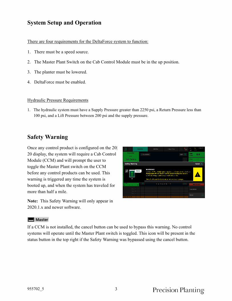
Safety Warning
Once any control product is configured on the 20|20 display, the system will require a Cab ControlModule (CCM) and will prompt the user totoggle the Master Plant switch on the CCMbefore any control products can be used. Thiswarning is triggered any time the system isbooted up, and when the system has traveled formore than half a mile.
Note: This Safety Warning will only appear in2020.1.x and newer software.
If a CCM is not installed, the cancel button can be used to bypass this warning. No controlsystems will operate until the Master Plant switch is toggled. This icon will be present in thestatus button in the top right if the Safety Warning was bypassed using the cancel button.
955702_5 4
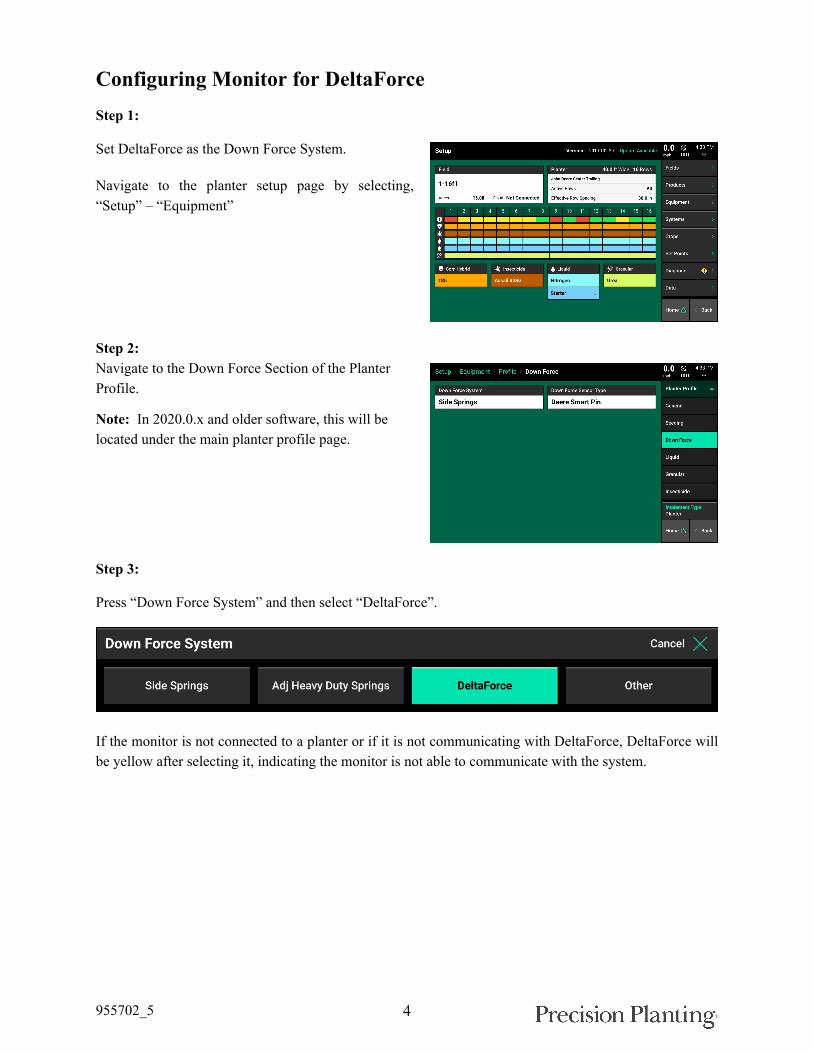
Configuring Monitor for DeltaForceStep 1:
Set DeltaForce as the Down Force System.
Navigate to the planter setup page by selecting,“Setup” – “Equipment”
Step 2:Navigate to the Down Force Section of the PlanterProfile.
Note: In 2020.0.x and older software, this will belocated under the main planter profile page.
Step 3:
Press “Down Force System” and then select “DeltaForce”.
If the monitor is not connected to a planter or if it is not communicating with DeltaForce, DeltaForce willbe yellow after selecting it, indicating the monitor is not able to communicate with the system.

955702_5 5
Step 4:
Once DeltaForce has been set as the Down Force System. Select the correct Down Force Sensor Type.
Step 5:On the home screen the DeltaForce control buttonwill appear on the right hand side of the screen in theStandard and Metrics tabs. It will display the DownForce Setting and the DeltaForce target value. Usethis button to access the DeltaForce control page. Formore information, see the DeltaForce Control sectionbelow.
DeltaForce Setup
Navigate to “Setup” - “Systems” - “DeltaForce”
The default DeltaForce settings will functionproperly for most situations. Adjust settings onlyif necessary.
955702_5 6
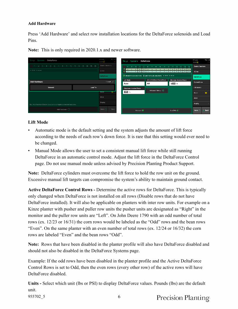
Add Hardware
Press ‘Add Hardware’ and select row installation locations for the DeltaForce solenoids and LoadPins.
Note: This is only required in 2020.1.x and newer software.
Lift Mode
• Automatic mode is the default setting and the system adjusts the amount of lift forceaccording to the needs of each row’s down force. It is rare that this setting would ever need tobe changed.
• Manual Mode allows the user to set a consistent manual lift force while still runningDeltaForce in an automatic control mode. Adjust the lift force in the DeltaForce Controlpage. Do not use manual mode unless advised by Precision Planting Product Support.
Note: DeltaForce cylinders must overcome the lift force to hold the row unit on the ground.Excessive manual lift targets can compromise the system’s ability to maintain ground contact.
Active DeltaForce Control Rows - Determine the active rows for DeltaForce. This is typicallyonly changed when DeltaForce is not installed on all rows (Disable rows that do not haveDeltaForce installed). It will also be applicable on planters with inter row units. For example on aKinze planter with pusher and puller row units the pusher units are designated as “Right” in themonitor and the puller row units are “Left”. On John Deere 1790 with an odd number of totalrows (ex. 12/23 or 16/31) the corn rows would be labeled as the “Odd” rows and the bean rows“Even”. On the same planter with an even number of total rows (ex. 12/24 or 16/32) the cornrows are labeled “Even” and the bean rows “Odd”.
Note: Rows that have been disabled in the planter profile will also have DeltaForce disabled andshould not also be disabled in the DeltaForce Systems page.
Example: If the odd rows have been disabled in the planter profile and the Active DeltaForceControl Rows is set to Odd, then the even rows (every other row) of the active rows will haveDeltaForce disabled.
Units - Select which unit (lbs or PSI) to display DeltaForce values. Pounds (lbs) are the defaultunit.

955702_5 7
Minimum Applied Force - The minimum amount of force that can be applied to each row unit.The default setting is -450 lbs. This value can be set from -450 to 0.
Maximum Applied Force - The maximum amount of force that can be applied to each row unit.The default setting is 650 lbs. The value can range from 0 to 650.
Advanced Setup - This contains a setting which will allow the user to disable the Low PressureDeltaForce popup.
Note: If this popup is disabled, DeltaForce will not alert the user to low pressure conditions.Low hydraulic pressure conditions will limit DeltaForce performance.
Load Cells
Navigate to “Setup” – “Diagnose” – “Load Cells”
This page displays Load Cell information as wellas control for zeroing and disabling load cells.
Load Cell values can be zeroed by pressing the“Zero All” button at the bottom of the page.Ensure the planter is raised when zeroing loadcells.
Reading (lbs) - displays the current weight that is being measured on each individual row.
Sensor Source - Identifies the type of module the Load Cell is plugged into.
Status - displays the status of each load cell. Selecting a row in the status column will allow theoperator to disable (ignore) the load cell on that row. To make a load cell active that has beenignored select that row in the status column.
Reference Value - This is a value that is used to give a Load Cell a true zero. A healthy referencevalue is between 28 and 36. Reference values will vary across the planter but all should be withinthis range.
Note: If a load cell is ignored, that row will control DeltaForce to the 80th percentile of all other properlyoperating rows.
Note: If the system suspects an issue with a load sensor, it will automatically ignore that load sensor.
Calibration Factor - The calibration factor will auto-populate based on the planter make andmodel selected and the Downforce Sensor type.
Calibration Factors for each type of load cell:
Load Cell Row Units Calibration Factor1/2” Load Pin John Deere 7000 and Kinze 2000 row units 85
955702_5 8
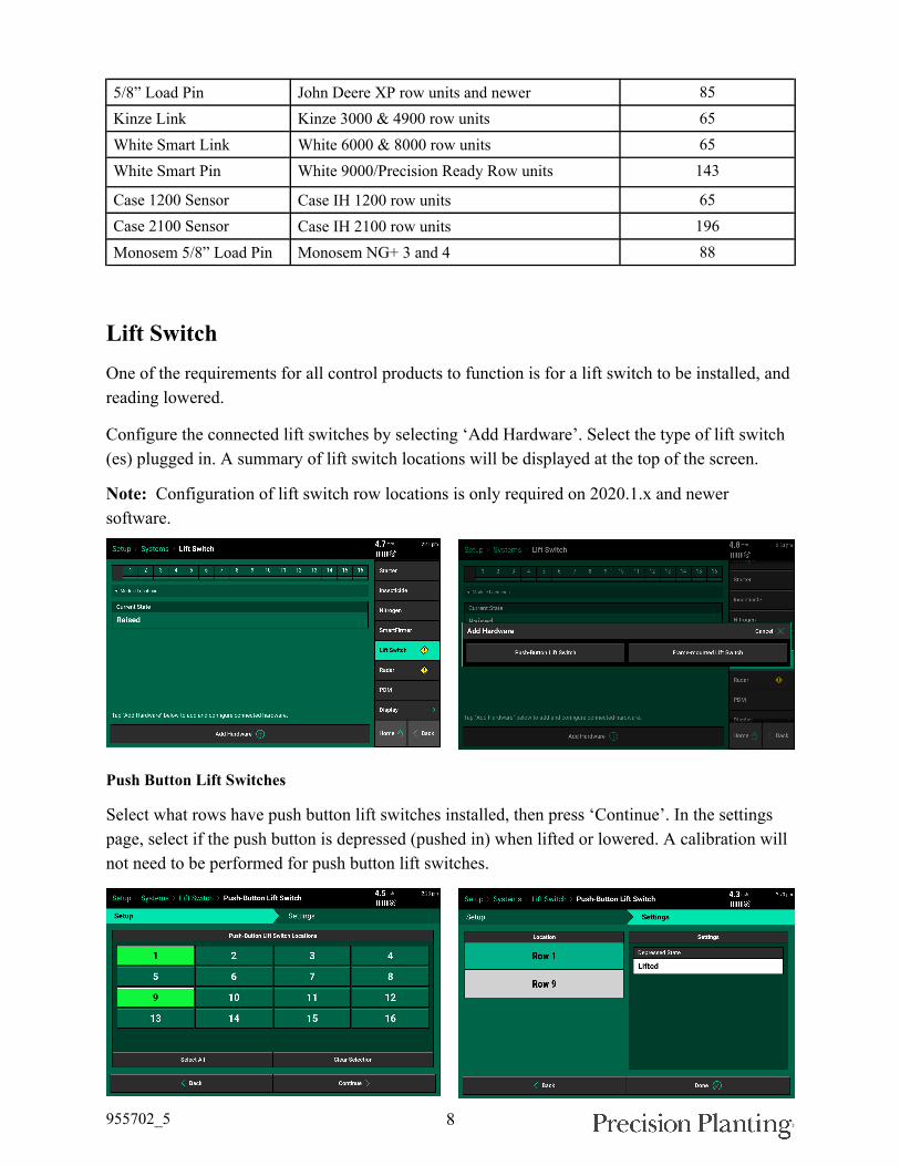
5/8” Load Pin John Deere XP row units and newer 85Kinze Link Kinze 3000 & 4900 row units 65White Smart Link White 6000 & 8000 row units 65White Smart Pin White 9000/Precision Ready Row units 143
Case 1200 Sensor Case IH 1200 row units 65Case 2100 Sensor Case IH 2100 row units 196Monosem 5/8” Load Pin Monosem NG+ 3 and 4 88
Lift SwitchOne of the requirements for all control products to function is for a lift switch to be installed, andreading lowered.
Configure the connected lift switches by selecting ‘Add Hardware’. Select the type of lift switch(es) plugged in. A summary of lift switch locations will be displayed at the top of the screen.
Note: Configuration of lift switch row locations is only required on 2020.1.x and newersoftware.
Push Button Lift Switches
Select what rows have push button lift switches installed, then press ‘Continue’. In the settingspage, select if the push button is depressed (pushed in) when lifted or lowered. A calibration willnot need to be performed for push button lift switches.

955702_5 9
Frame Mounted Lift Switches
For a frame mounted switch, configure the plug in location as the PDM. Once the PDM isselected as the location, the system will then need to be calibrated for lifted and lowered position.
Calibrate Lift Switch
To complete the Lift Switch calibration, press the“Run Calibration” button at the bottom of thescreen. Follow the onscreen instructions for thedifferent positions the planter must be in. Theresults will then be displayed on the main LiftSwitch Page. For issues with the lift switch notcalibrating or functioning correctly, see theTroubleshooting Guides for Lift Switches in theDealer Service Manual. After a calibration hasbeen completed, verify the system is reading thelift switch correctly by watching the “CurrentState” information on the Lift Switch page.Ensure the “Current State” is correct whenlowering and lifting the planter.
Manual entry of values can be done by selecting the “Lowered Percent”, “Lifted Percent”, or“Planting Percent” buttons and entering a value.
To clear out the current calibration press the “Clear Calibration” button located at the bottom ofthe screen.
955702_5 10
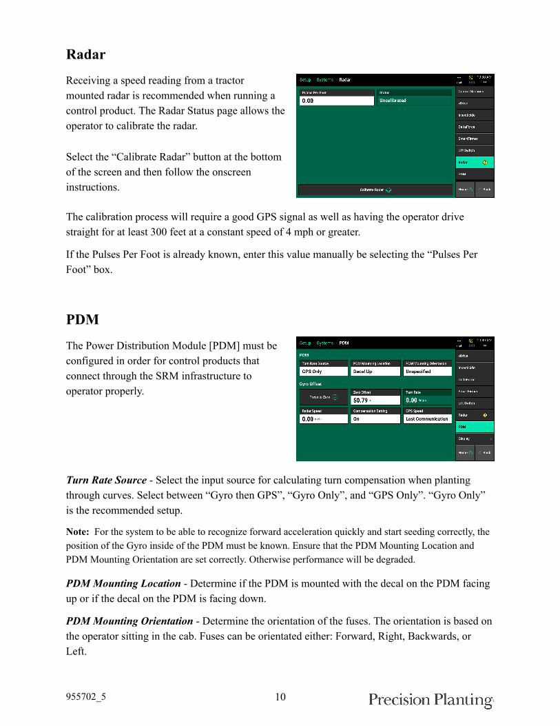
Radar
Receiving a speed reading from a tractormounted radar is recommended when running acontrol product. The Radar Status page allows theoperator to calibrate the radar.
Select the “Calibrate Radar” button at the bottomof the screen and then follow the onscreeninstructions.
The calibration process will require a good GPS signal as well as having the operator drivestraight for at least 300 feet at a constant speed of 4 mph or greater.
If the Pulses Per Foot is already known, enter this value manually be selecting the “Pulses PerFoot” box.
PDM
The Power Distribution Module [PDM] must beconfigured in order for control products thatconnect through the SRM infrastructure tooperator properly.
Turn Rate Source - Select the input source for calculating turn compensation when plantingthrough curves. Select between “Gyro then GPS”, “Gyro Only”, and “GPS Only”. “Gyro Only”is the recommended setup.
Note: For the system to be able to recognize forward acceleration quickly and start seeding correctly, theposition of the Gyro inside of the PDM must be known. Ensure that the PDM Mounting Location andPDM Mounting Orientation are set correctly. Otherwise performance will be degraded.
PDMMounting Location - Determine if the PDM is mounted with the decal on the PDM facingup or if the decal on the PDM is facing down.
PDMMounting Orientation - Determine the orientation of the fuses. The orientation is based onthe operator sitting in the cab. Fuses can be orientated either: Forward, Right, Backwards, orLeft.

955702_5 11
“Press to Zero” - use this button to zero the gyro. The gyro should always be zeroed whensetting up a new system. There will be a Zero Offset percentage recorded after the gyro has beenzeroed. Make sure the planter is straight behind the tractor when zeroing the gyro. If the turncompensation seems to be off or if getting warnings about the gyro, re-zero the gyro.
Zero Offset - Displays the zero offset set when the Gyro was zeroed.
Turn Rate - Displays the radius of a turn in degrees per second, of the turn that is being readfrom the gyro while turning. This is the degree that will be used for turn compensation.
Compensation Setting - Press on this button to adjust the turn compensation.
On - This is the RECOMMENDED and default setting for all SRM systems. In this setting,both control and monitoring will be based on the speed of each individual row. For example;all rows will keep a consistent seed spacing around curves.
Control Only - Each row will control to its own calculated speed and will keep consistentseed spacing. However, the reporting will only show a population based on the center of theplanter. There will be a higher population on the outside rows and lower population on theinside rows of the curve.
Monitor Only - Control for all rows will be based on the center of the planter. However,reporting will show a population based on the distance each individual row traveled.Resulting in a higher population for the inside rows and lower populations for the outsiderows.
Off - both control and monitoring will be based on the speed of the tractor. Seed Spacingwill be closer on the inside of the curve and further apart on the outside of the curve.
Radar Speed - displays the speed being read from the Radar. Press on this button to be directed tothe Radar Status page.
GPS Speed - displays the speed being read from GPS. Press on this button to be directed to theGPS Communication page.
DeltaForce Control
The DeltaForce system control button controlsthe system and displays the status. If this buttonis not located on the home screen, see the 20|20Operator’s Guide for information on configuringthe home screen.
If the DeltaForce system is disabled, theDeltaForce control button will be red and displayDisabled.
955702_5 12
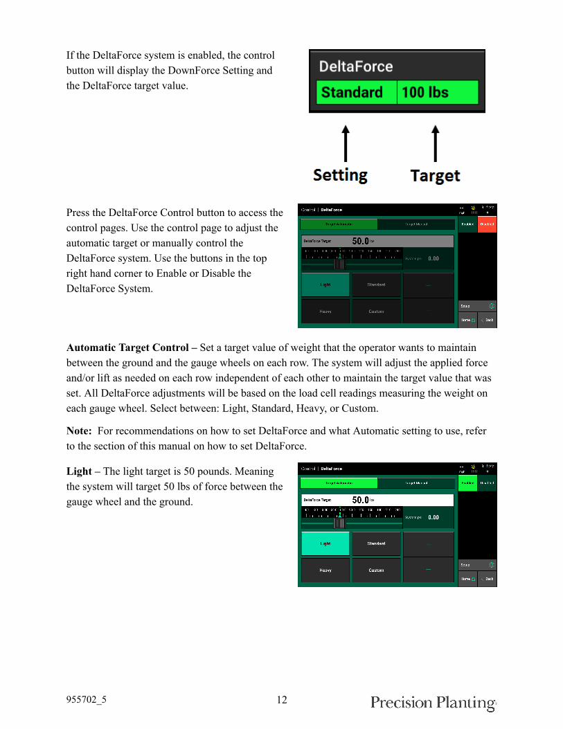
If the DeltaForce system is enabled, the controlbutton will display the DownForce Setting andthe DeltaForce target value.
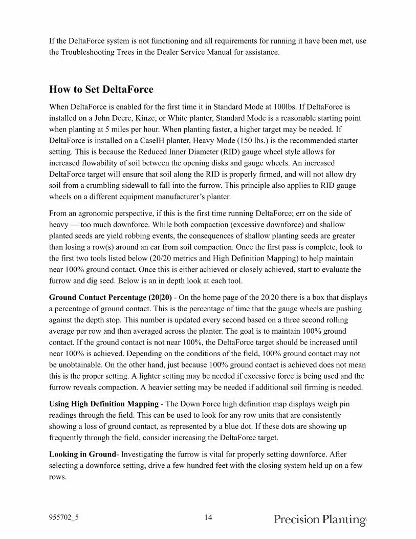
Press the DeltaForce Control button to access thecontrol pages. Use the control page to adjust theautomatic target or manually control theDeltaForce system. Use the buttons in the topright hand corner to Enable or Disable theDeltaForce System.
Automatic Target Control – Set a target value of weight that the operator wants to maintainbetween the ground and the gauge wheels on each row. The system will adjust the applied forceand/or lift as needed on each row independent of each other to maintain the target value that wasset. All DeltaForce adjustments will be based on the load cell readings measuring the weight oneach gauge wheel. Select between: Light, Standard, Heavy, or Custom.
Note: For recommendations on how to set DeltaForce and what Automatic setting to use, referto the section of this manual on how to set DeltaForce.
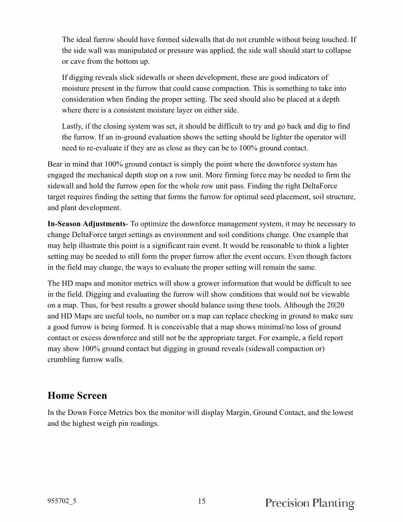
Light – The light target is 50 pounds. Meaningthe system will target 50 lbs of force between thegauge wheel and the ground.

955702_5 13
Standard – The standard target is 100 pounds.This is the default setting.
Heavy – The heavy target is 150 pounds.
Custom – This control mode allows the operatorto set any target value (up to 195 lbs.) while stillmaintaining automatic control. Use the plus andminus arrows to adjust the target value.
The DeltaForce system may also be operated inManual Mode. This control mode allows theoperator to designate a desired force for thesystem to maintain. Both a Lift Force and aDown Force value can be entered. When usingManual Mode, weigh pin readings are not takeninto account and all cylinders will apply a singleforce to all rows until manually changed by theoperator.
Use the Plus and Minus arrows to adjust the Liftand Down Force targets. Net applied force willbe displayed at the top of the screen.
System PSI displays the current PSI reading from the pressure sensor located on the DeltaForceLift Manifold.
955702_5 14
If the DeltaForce system is not functioning and all requirements for running it have been met, usethe Troubleshooting Trees in the Dealer Service Manual for assistance.
How to Set DeltaForceWhen DeltaForce is enabled for the first time it in Standard Mode at 100lbs. If DeltaForce isinstalled on a John Deere, Kinze, or White planter, Standard Mode is a reasonable starting pointwhen planting at 5 miles per hour. When planting faster, a higher target may be needed. IfDeltaForce is installed on a CaseIH planter, Heavy Mode (150 lbs.) is the recommended startersetting. This is because the Reduced Inner Diameter (RID) gauge wheel style allows forincreased flowability of soil between the opening disks and gauge wheels. An increasedDeltaForce target will ensure that soil along the RID is properly firmed, and will not allow drysoil from a crumbling sidewall to fall into the furrow. This principle also applies to RID gaugewheels on a different equipment manufacturer’s planter.
From an agronomic perspective, if this is the first time running DeltaForce; err on the side ofheavy — too much downforce. While both compaction (excessive downforce) and shallowplanted seeds are yield robbing events, the consequences of shallow planting seeds are greaterthan losing a row(s) around an ear from soil compaction. Once the first pass is complete, look tothe first two tools listed below (20/20 metrics and High Definition Mapping) to help maintainnear 100% ground contact. Once this is either achieved or closely achieved, start to evaluate thefurrow and dig seed. Below is an in depth look at each tool.
Ground Contact Percentage (20|20) - On the home page of the 20|20 there is a box that displaysa percentage of ground contact. This is the percentage of time that the gauge wheels are pushingagainst the depth stop. This number is updated every second based on a three second rollingaverage per row and then averaged across the planter. The goal is to maintain 100% groundcontact. If the ground contact is not near 100%, the DeltaForce target should be increased untilnear 100% is achieved. Depending on the conditions of the field, 100% ground contact may notbe unobtainable. On the other hand, just because 100% ground contact is achieved does not meanthis is the proper setting. A lighter setting may be needed if excessive force is being used and thefurrow reveals compaction. A heavier setting may be needed if additional soil firming is needed.
Using High Definition Mapping - The Down Force high definition map displays weigh pinreadings through the field. This can be used to look for any row units that are consistentlyshowing a loss of ground contact, as represented by a blue dot. If these dots are showing upfrequently through the field, consider increasing the DeltaForce target.
Looking in Ground- Investigating the furrow is vital for properly setting downforce. Afterselecting a downforce setting, drive a few hundred feet with the closing system held up on a fewrows.
955702_5 15
The ideal furrow should have formed sidewalls that do not crumble without being touched. Ifthe side wall was manipulated or pressure was applied, the side wall should start to collapseor cave from the bottom up.
If digging reveals slick sidewalls or sheen development, these are good indicators ofmoisture present in the furrow that could cause compaction. This is something to take intoconsideration when finding the proper setting. The seed should also be placed at a depthwhere there is a consistent moisture layer on either side.
Lastly, if the closing system was set, it should be difficult to try and go back and dig to findthe furrow. If an in-ground evaluation shows the setting should be lighter the operator willneed to re-evaluate if they are as close as they can be to 100% ground contact.
Bear in mind that 100% ground contact is simply the point where the downforce system hasengaged the mechanical depth stop on a row unit. More firming force may be needed to firm thesidewall and hold the furrow open for the whole row unit pass. Finding the right DeltaForcetarget requires finding the setting that forms the furrow for optimal seed placement, soil structure,and plant development.
In-Season Adjustments- To optimize the downforce management system, it may be necessary tochange DeltaForce target settings as environment and soil conditions change. One example thatmay help illustrate this point is a significant rain event. It would be reasonable to think a lightersetting may be needed to still form the proper furrow after the event occurs. Even though factorsin the field may change, the ways to evaluate the proper setting will remain the same.
The HD maps and monitor metrics will show a grower information that would be difficult to seein the field. Digging and evaluating the furrow will show conditions that would not be viewableon a map. Thus, for best results a grower should balance using these tools. Although the 20|20and HD Maps are useful tools, no number on a map can replace checking in ground to make surea good furrow is being formed. It is conceivable that a map shows minimal/no loss of groundcontact or excess downforce and still not be the appropriate target. For example, a field reportmay show 100% ground contact but digging in ground reveals (sidewall compaction or)crumbling furrow walls.
Home ScreenIn the Down Force Metrics box the monitor will display Margin, Ground Contact, and the lowestand the highest weigh pin readings.
955702_5 16
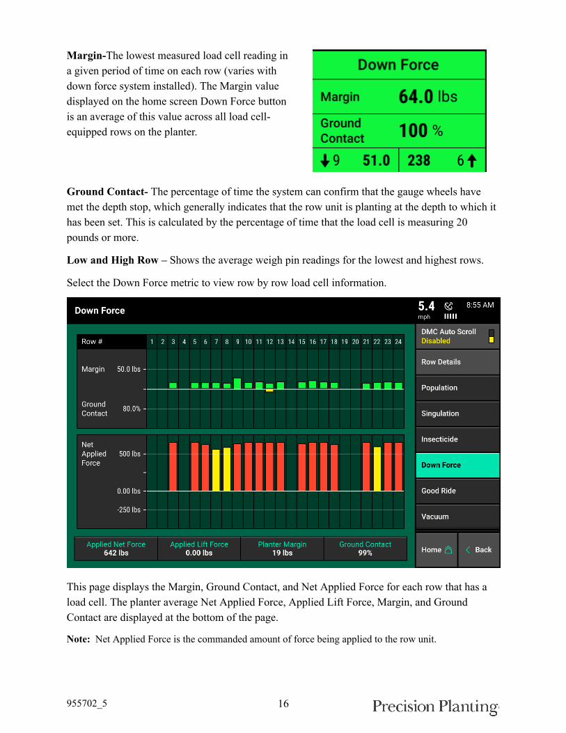
Margin-The lowest measured load cell reading ina given period of time on each row (varies withdown force system installed). The Margin valuedisplayed on the home screen Down Force buttonis an average of this value across all load cell-equipped rows on the planter.
Ground Contact- The percentage of time the system can confirm that the gauge wheels havemet the depth stop, which generally indicates that the row unit is planting at the depth to which ithas been set. This is calculated by the percentage of time that the load cell is measuring 20pounds or more.
Low and High Row – Shows the average weigh pin readings for the lowest and highest rows.
Select the Down Force metric to view row by row load cell information.
This page displays the Margin, Ground Contact, and Net Applied Force for each row that has aload cell. The planter average Net Applied Force, Applied Lift Force, Margin, and GroundContact are displayed at the bottom of the page.
Note: Net Applied Force is the commanded amount of force being applied to the row unit.
955702_5 17
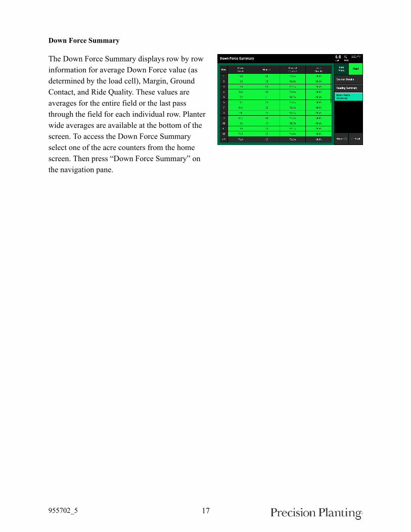
Down Force Summary
The Down Force Summary displays row by rowinformation for average Down Force value (asdetermined by the load cell), Margin, GroundContact, and Ride Quality. These values areaverages for the entire field or the last passthrough the field for each individual row. Planterwide averages are available at the bottom of thescreen. To access the Down Force Summaryselect one of the acre counters from the homescreen. Then press “Down Force Summary” onthe navigation pane.
955702_5 18
Maps
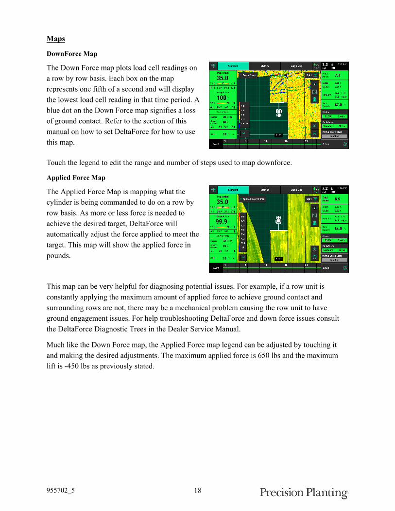
DownForce Map
The Down Force map plots load cell readings ona row by row basis. Each box on the maprepresents one fifth of a second and will displaythe lowest load cell reading in that time period. Ablue dot on the Down Force map signifies a lossof ground contact. Refer to the section of thismanual on how to set DeltaForce for how to usethis map.
Touch the legend to edit the range and number of steps used to map downforce.
Applied Force Map
The Applied Force Map is mapping what thecylinder is being commanded to do on a row byrow basis. As more or less force is needed toachieve the desired target, DeltaForce willautomatically adjust the force applied to meet thetarget. This map will show the applied force inpounds.
This map can be very helpful for diagnosing potential issues. For example, if a row unit isconstantly applying the maximum amount of applied force to achieve ground contact andsurrounding rows are not, there may be a mechanical problem causing the row unit to haveground engagement issues. For help troubleshooting DeltaForce and down force issues consultthe DeltaForce Diagnostic Trees in the Dealer Service Manual.
Much like the Down Force map, the Applied Force map legend can be adjusted by touching itand making the desired adjustments. The maximum applied force is 650 lbs and the maximumlift is -450 lbs as previously stated.

955702_5 19
DeltaForce Diagnostic InformationPrior to planting, ensure that all planter diagnostic information is ok. Select “Setup” –“Diagnose”. Everything should be green on the diagnose page. If there is an issue on a row orrows, it will be indicated on the level 1 diagnose page by displaying the system that is having anissue in a color other than green.
Color Legend:
Green - the system is working correctly and communications are good. Select “Color Legend” toview an explanation of what each color indicates.
Yellow – a Device or sub-component is not 100%.
Red – Device has failed, or is expected, but not detected.
White – Device is detected, but is not expected.
Black – Row has been disabled in the planter configuration.
Gray – Device is being detected, updating firmware, or unreachable.
Note: Modules may be updating during initial connection. Once updates are complete, all modules shouldbe green. If the modules are not green, confirm that the number of rows and planter setup is correct. If stillexperiencing issues, refer to the Dealer Service Manual.
The DeltaForce button will be green if the system is configured and communication isestablished. If it is not green, press it to view DeltaForce level 2 row-by- row diagnostics.

955702_5 20
Load Cell (lbs) – Displays the current weightbeing measured on each individual row by theload cell.
Solenoid Volts – Voltage being sent to thesolenoid controlling the valve for the DeltaForcecylinder.
Commanded Pressure – The pressure that theDeltaForce system is commanding each row toapply.
Commanded Force (lbs) – The amount of weight in pounds which the DeltaForce system iscommanding each row to apply. Negative values represent lift while positive values representapplied force.
Net Applied Downforce (lbs) – Amount of weight that the DeltaForce system is adding orsubtracting to the weight of the row unit.
At the bottom of the DeltaForce diagnostic page there is an indicator for the state of the LiftSwitch, Master Plant Switch, and the Control Mode. The Supply Pressure value is the currentpressure reading on the lift valve of the Lift Manifold (Pressure must be greater than 2250 foroptimal performance from DeltaForce). Additionally, both GPS and Radar speed readings aredisplayed.
DeltaForce Health Checks
Always perform a health check on the DeltaForcesystem after installation and at the start of everyseason. Perform any health checks in yellowbefore planting. Access the DeltaForce healthcheck page by selecting “Setup” – “Diagnose” –“Health Checks” or by pressing the DeltaForceHealth Checks button on the DeltaForce level 2diagnose page. There are four DeltaForce HealthChecks that can be run.
The Air Purge Test, Applied Force Test, and Advanced Applied Test are visual tests and theoperator must determine if the system passed or failed the health check. The Voltage Current Testwill give the user a report card to determine if each row passed the health check. If the test isfailed, the area it failed will be highlighted in yellow along with the row number on the resultsscreen.
955702_5 21
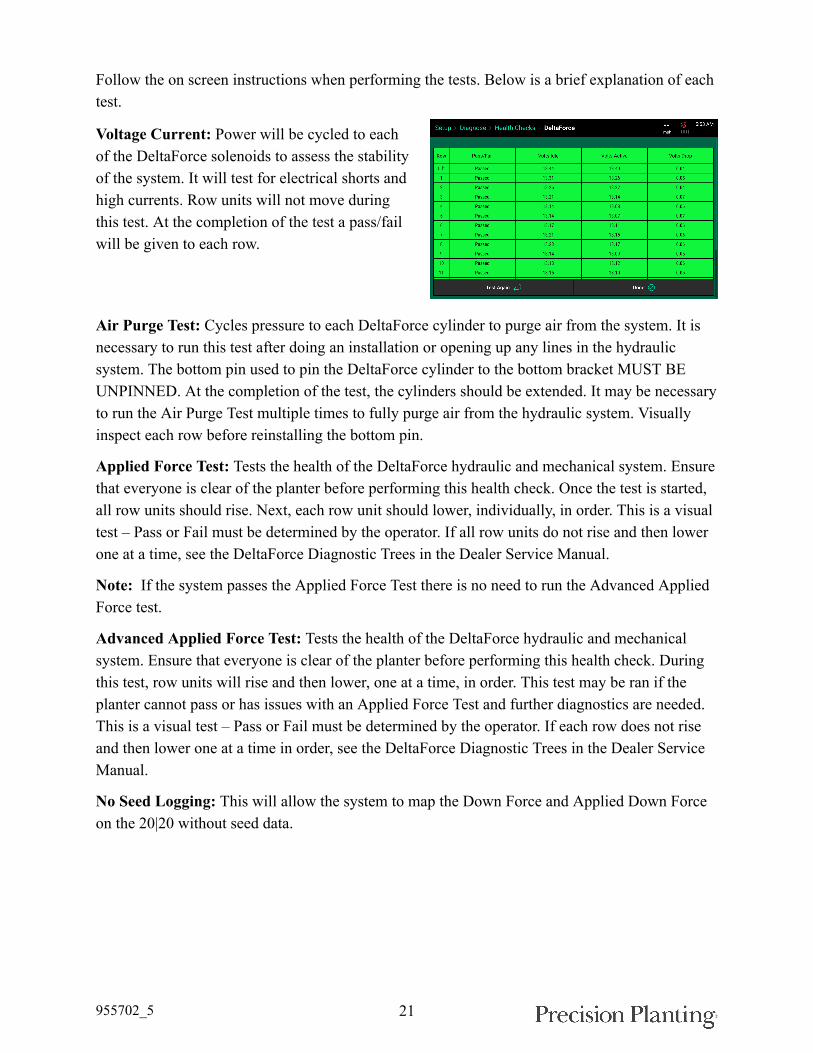
Follow the on screen instructions when performing the tests. Below is a brief explanation of eachtest.
Voltage Current: Power will be cycled to eachof the DeltaForce solenoids to assess the stabilityof the system. It will test for electrical shorts andhigh currents. Row units will not move duringthis test. At the completion of the test a pass/failwill be given to each row.
Air Purge Test: Cycles pressure to each DeltaForce cylinder to purge air from the system. It isnecessary to run this test after doing an installation or opening up any lines in the hydraulicsystem. The bottom pin used to pin the DeltaForce cylinder to the bottom bracket MUST BEUNPINNED. At the completion of the test, the cylinders should be extended. It may be necessaryto run the Air Purge Test multiple times to fully purge air from the hydraulic system. Visuallyinspect each row before reinstalling the bottom pin.
Applied Force Test: Tests the health of the DeltaForce hydraulic and mechanical system. Ensurethat everyone is clear of the planter before performing this health check. Once the test is started,all row units should rise. Next, each row unit should lower, individually, in order. This is a visualtest – Pass or Fail must be determined by the operator. If all row units do not rise and then lowerone at a time, see the DeltaForce Diagnostic Trees in the Dealer Service Manual.
Note: If the system passes the Applied Force Test there is no need to run the Advanced AppliedForce test.
Advanced Applied Force Test: Tests the health of the DeltaForce hydraulic and mechanicalsystem. Ensure that everyone is clear of the planter before performing this health check. Duringthis test, row units will rise and then lower, one at a time, in order. This test may be ran if theplanter cannot pass or has issues with an Applied Force Test and further diagnostics are needed.This is a visual test – Pass or Fail must be determined by the operator. If each row does not riseand then lower one at a time in order, see the DeltaForce Diagnostic Trees in the Dealer ServiceManual.
No Seed Logging: This will allow the system to map the Down Force and Applied Down Forceon the 20|20 without seed data.