Embed Size (px)
Citation preview
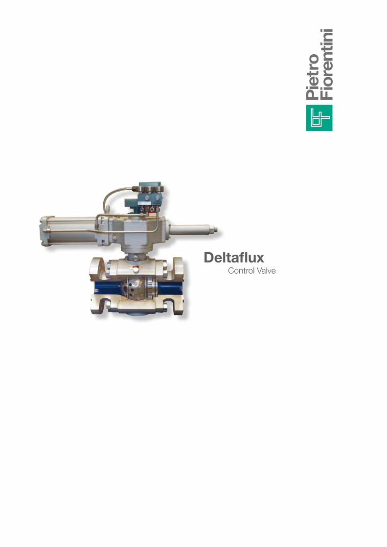
DeltafluxControl Valve

Deltaflux
DeltafluxValvola di regolazione
Deltaflux control valve is an ideal solution for all fluid control applications where high differential pressure or great flow rates are involved.The refined design of the rotating trim allows offering simultaneously high flow rate coefficients Cv and minimum pressure drops in fully open position, thus creating a unique combination of capacity and rangeability.Thanks to its versatility and to the available range, Deltaflux is the ideal solution for all special applications, as well as for use at high and low temperatures, and in aggressive environments. Considering its features, Deltaflux is the ideal primary element for ESD (Emergency Shut Down) and HIPPS (High Integrity Pipeline Protection System) systems.
Fields of application:- Natural gas industry- Energy- Petrochemical industry- Water transport
Capacity: Here it is meant the capacity of keeping constant the flow rate that a valve can provide. The capacity is linked to the Cv coefficient of the valve. Rangeability: Rangeability is defined as the ratio between nominal flow rate coefficient Cv of the valve and controllable Cv. During plant design, the attainment of the highest possible rangeability factor (200-1) is obviously sought.
GlossaRy

DesiGneD to meet all neeDs
- HiGH CapaCity - Use VeRsatility
- RanGeability Ratio (200:1) - metal-metal tiGHtness
- low noise leVel - low pRessURe DRop
Deltaflux valves are control valves equipped with rotating trim, which allows attaining a unique solution for those applications involving great fluid flow rates. Deltaflux valves can be used within systems controlling the flow rate or pressure on pipelines, limiting the flow rate at LNG terminal output, controlling the pressure on primary reduction plants or, thanks to the limited pressure drops involved, as control element on ESD and HIPPS emergency systems.The wide range of materials and trims, both standard and customized, as well as of pneumatic, electric and electro-pneumatic actuators, allows selecting of specific control valve for each application.

Deltaflux control valves are equipped with special regulating trims making it suitable for applications involving gases or liquids. Moreover, the trim is studied in order to hinder the formation of dirt deposits inside the same
The trim configuration and the special geometries of Deltaflux allow attaining a high rangeability; moreover, they avoid overpressure within the valve body, thus obtaining a high noise reduction and a longer life-cycle of the sealing parts.
Deltaflux valves are a “Bolted body” project, thus they are easily maintainable. Sealing parts are interchangeable: Moreover, assembling of any kind of controls and accessories is quite easy.
Deltaflux valves, in their standard version, have been developed for a design temperature ranging from -29°C and + 121°C and for a storage temperature ranging from - 40 and + 60°C.
Deltaflux control valves are available up to a 24” diameter, thus allowing regulating also great fluid flow rates.
main features Deltaflux
Deltaflux valves, thanks to its special customized design can be used for HIPPS system for both gas and liquid medium. In this applications it is requested a quick closure time (t < 3 sec) avoiding damages for the water hummer effects on the valves or on the plant. Thanks to DELTAFLUX valves it is possible to re-open the flow after the shut off in a way that can grand a modular re-pressurization of the downstream pipe to protect all the instrumentation. This can be reached without the use of a by-pass. DELTAFLUX valves are complete of PFD ( probability of Failure on Demand ) Assessment Report – SIL 3.
- Rating according to ASME B 16.34 (ANSI 150, 300, 600, 900, 1500);- “End to end dimension” according to API 6D;- “End flanges” according to ASME B16.5;- Tightness class FCI 70-2-2003;- NACE MR0175-2002.
Reference regulations Deltaflux
Hipps (High pressure protection system) application: Deltaflux

Deltaflux
bodybonnets boltsseatballstemControl trimseals
ASTM A 350 LF2ASTM A 350 LF2ASTM A 193 – B7 ASTM A 194 – 2H AISI 410 + TUNGSTEN CARBIDEASTM A 105 Steel UNS 17400S235JR + ENP 20µmNitrile – Viton
mateRials Deltaflux
the above listed features refer to normal production execution.special executions and materials can be supplied, upon request, for specific uses.

The need to transfer large flow rates with minimal pressure drops on the control valve requires a combination of wide capacity and high rangeability.Valves with a rotating trim are characterized by a high capacity associated to a relevant recovery.Within the framework of typical pressure reduction applications, high recovery results in conditions of critical heads, high speed and, consequently, noise associated to different nature problems.Deltaflux valve is equipped with trims characterized by a low recovery factor, thus offering the optimal solution to such problems also under conditions of high differential pressures.Deltaflux valve can be used also to control liquids.
Thanks to a special trim, it remarkably reduces negative effects of cavitations, such as the tear of surfaces close to the involved area, and the emission of noise typical of this phenomenon.
Cavitation: It occurs every time the static pressure downstream is greater than the liquid vapor pressure, and when the static pressure, in any point inside the valve, is lower than or equal to the liquid vapor pressure.Vapor bubbles do form in the minimum static pressure area and then collapse, imploding as they pass downstream, in an area with higher static pressure, thus generating noise.The noise generated by cavitation is frequently described as a rattling sound similar to that which would be crated if gravel were present in the fluid.
Control applications for gases and liquids Deltaflux
trim for gases trim for liquids example of analyzed fluid
GlossaRy

Standard Deltaflux valves are available in both the one-way and two-way version.The standard version is one-way and assures a tightness class V according to FCI 70-2-2003 in the flow direction.In the two-way version, the valve, equipped with specific seal for each flow direction, assures a tightness class V in the main flow direction and a tightness class IV for the reverse flow.
Deltaflux control valves can be driven by pneumatic actuators.Pneumatic actuators can be supplied with both simple action and double action, for any valve size. Moreover, they can be equipped with accessories able to meet any application or request requirements.
pneUmatiC aCtUatoRs
Deltaflux control valves can be driven also by electric actuators.The electric actuators used are available in both the multi-revolution and modulating version; both versions are characterized by all those features making them easy to use both locally and remotely.
noteEach accessory is available upon customer’s request for all valve sizes and configurations.Moreover, it is possible to customize the production or develop solutions requested by the customer.Always refer to Pietro Fiorentini S.p.A. for any explanation or feasibility study.
one-way & two-way Deltaflux
eleCtRiC aCtUatoRs

actuator supplied with natural Gas and driven by 4-20 ma signal.In this configuration, Deltaflux control valve is characterized by the use of the electro-pneumatic positioner, installed on the Double Action Pneumatic control.The positioner works in modulating mode thanks to the electric control signal (4-20 mA) coming from a pulse generator.The electro-pneumatic positioner is in charge of assuring an excellent proportionality between the electro-pneumatic control signal feeding the valve and the actuator stroke.The system can consists also of a reduction panel, equipped with filter and pressure reduction unit, to feed the electro-pneumatic positioner.Moreover, it is possible to install also an anti-freeze pressure regulator directly on the main line (for applications using natural gas).The system can be feed with both instrument air and line natural gas.
Deltaflux for regulating using a pneumatic signal Deltaflux
layout of a gas application
4-20 mA Feedback Position Signal 4-20 mA

actuator supplied with natural gas and driven by pneumatic controller.In this configuration, Deltaflux control valve, thanks to the use of an instrument suitable to control variables such as the pressure of liquids or gases, is able to compare the fluid pressure measured value with the set-point value.The comparison between the two quantities generates a standard modulating signal of 3-15 psi that in its turn controls the pneumatic positioner assuring an excellent proportionality between the pneumatic signal feeding the valve and the actuator stroke.
layout of a gas application Deltaflux
Deltaflux for regulating using a pneumatic signal Deltaflux

It is possible to install a safety device (line off), which immediately blocks gas flow, when due to a fault downstream pressure increases and reaches the maximum pre-set value for its operation.Otherwise, the device can be enabled also manually by bringing Deltaflux valve immediately to closed (shut off) position thanks to the pneumatic control by simple action (fail to close).
In this case, the Monitor emergency control valve is installed upstream of the service control valve, in the gas flow direction.The monitor is an emergency control valve, which is in charge of taking over the main control valve operation, in case this latter due to an anomaly or fault allows the output pressure to reach the calibration pressure set for the monitor tripping.The two devices are actually identical in terms of mechanical parts.Only, the monitor has a tripping calibration higher than that of the main control valve.
Deltaflux
Deltaflux
layout of a gas application
Deltaflux for regulating using a pneumatic signal and a shut off system
Deltaflux for regulating using a pneumatic signal and an in-line monitor

layout of a gas application
Here below there is the characteristic graphical representation of Cv of Deltaflux control valves.
Cv coefficient for gas
Opening degree of the control valve [%]
Flow rate coefficient Deltaflux

Given data are obtained by tests carried out both at internal laboratories and at primary international laboratories. The tables provide the Cv value at 100% of opening for each ball passage diameter.
Note: To verify the dimensioning and, in detail, for the dimensioning of Deltaflux control valves bigger than 24”, always refer to Pietro Fiorentini S.p.A.
This table provides the flow rate coefficient Cv, the recovery factor, and the incipient cavitation factor to be used in the formulas according to the valve opening degree.
example
Deltaflux control valve, Trim for gas, DN 12” at 30 degrees of opening angle:
Factor Cv = 2825 x 0,071 = 200.5Recovery factor F = 0.89Incipient cavitation factor Kc = 0.79
Gas control application
Cv coefficient at 100% opening
Cv coefficient at 100% opening
Gas trim
opening angle
Gas trim
Cv multiplier factor
Cv multiplier factor
Recovery factor F
Recovery factor F
incipient cavitation factor Kc
incipient cavitation factor Kc
liquid trim
liquid trim

overall dimensions of full bore Deltaflux control valves Deltaflux
BH
RF - RJ BW
DN D
* Stem dimension** Actuator coupling flange
BH
RF - RJ BW
DN D

DeltafluxFull bore
The execution with other dimensions than the ones given in the table can be assessed according to the specific needs.
* Stem dimension** Actuator coupling flange
Dimensioni d’ingombro valvole di regolazione Deltaflux a passaggio ridotto
BH
RF - RJ BW
DN D
* Stem dimension** Actuator coupling flange
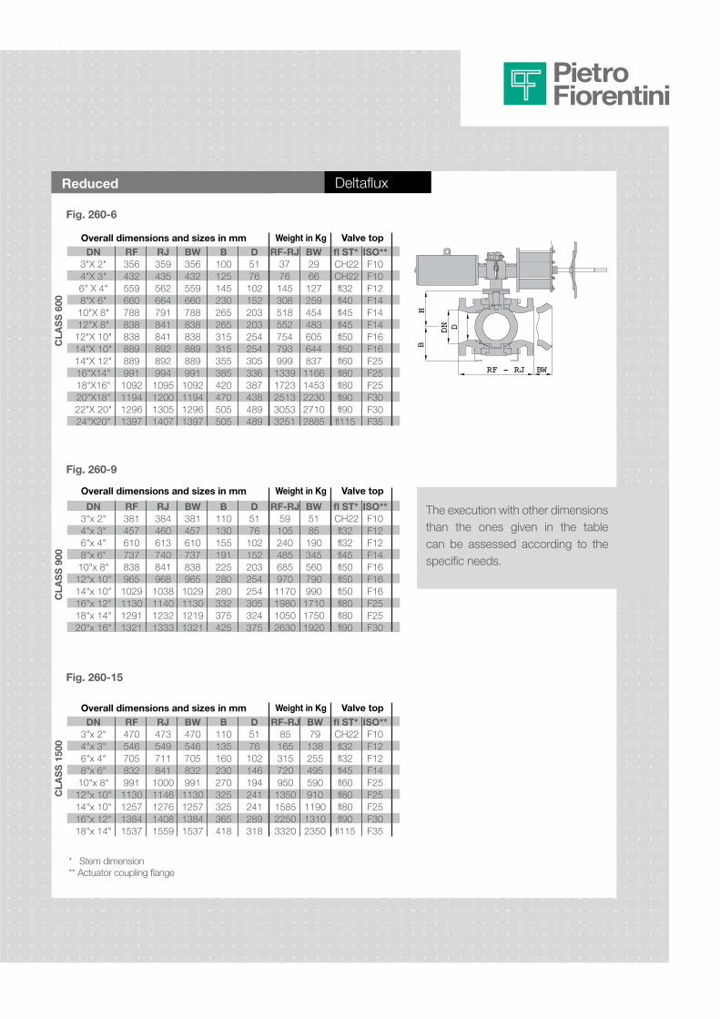
DeltafluxReduced
The execution with other dimensions than the ones given in the table can be assessed according to the specific needs.
* Stem dimension** Actuator coupling flange
BH
RF - RJ BW
DN D
Dn3"x 2"4"x 3"6"x 4"8"x 6"10"x 8"12"x 10"14"x 10"16"x 12"18"x 14"
RF4705467058329911130125713841537
RJ47354971184110001146127614081559
bw4705467058329911130125713841537
b110135160230270325325365418
D5176102146194241241289318
RF-RJ851653157209501350158522503320
bw79138255495590910119013102350
fl st*CH22fl32fl32fl45fl60fl80fl80fl90fl115
iso**F10F12F12F14F25F25F25F30F35
Dn3"x 2"4"x 3"6"x 4"8"x 6"10"x 8"12"x 10"14"x 10"16"x 12"18"x 14"20"x 16"
RF3814576107378389651029113012911321
RJ3844606137408419681038114012321333
bw3814576107378389651029113012191321
b110130155191225280280332375425
D5176102152203254254305324375
RF-RJ591052404856859701170198010502630
bw5185190345560790990171017501920
fl st*CH22fl32fl32fl45fl50fl50fl50fl80fl80fl90
iso**F10F12F12F14F16F16F16F25F25F30
Dn3"X 2"4"X 3"6" X 4"8"X 6"10"X 8"12"X 8"12"X 10"14"X 10"14"X 12"16"X14"18"X16"20"X18"22"X 20"24"X20"
RF3564325596607888388388898899911092119412961397
RJ3594355626647918418418928929941095120013051407
bw3564325596607888388388898899911092119412961397
b100125145230265265315315355385420470505505
D5176102152203203254254305336387438489489
RF-RJ377614530851855275479399913391723251330533251
bw296612725945448360564483711661453223027102885
fl st*CH22CH22fl32fl40fl45fl45fl50fl50fl60fl80fl80fl90fl90fl115
iso**F10F10F12F14F14F14F16F16F25F25F25F30F30F35

Pietro Fiorentini S.p.A.via E.Fermi 8/10I-36057 Arcugnano (VI) ItalyTel. +39 0444 968.511Fax. +39 0444 960.468
CT-s540-E October 2013
via Rosellini 1I-20124 MilanoItalyTel. +39 02 696.14.21Fax. +39 02 688.04.57
www.fiorentini.com
The data contained is not binding. We reserve the right to changes without prior notice.
HIPPS Multiphase meterPressure reducing stations
pietro Fiorentini solutions


![Operation Manual Series 47K Gas Detector [SIL 2] - …geofire.it/wp-content/uploads/downloads/2015/03/47K_10052472-Rev0… · GB SAFETY REGULATIONS MSA 6 Series 47K Gas Detector [SIL](https://img.pdfslide.us/doc/110x75/5bb8029809d3f2333b8bb108/operation-manual-series-47k-gas-detector-sil-2-gb-safety-regulations-msa.jpg)
![Operation Manual Series 47K Gas Detector [SIL 2]...MSA EC DECLARATION OF CONFORMITY Series 47K Gas Detector [SIL 2] 3 EC Declaration of Conformity The manufacturer MSA AUER GmbH Thiemannstr](https://img.pdfslide.us/doc/110x75/60d5f53bb028fb6987521b9a/operation-manual-series-47k-gas-detector-sil-2-msa-ec-declaration-of-conformity.jpg)