Embed Size (px)
Citation preview

ZX-T Series
Cat. No. I205E-EN-01
Delta Robot 5 Axes
USER´S MANUAL
Delta RobotCR_UGD5 Series

CONTENTS Delta Robot 5 AxesUser's Manual
T-1
Safety Instructions
1. Attention S-1
2. Explanation of warnings and notes S-1
3. Safety information S-2
3.1 General S-23.2 Qualifiedpersonnel S-23.3 Liability S-23.4 Installationandoperatingconditions S-23.5 Residualrisks S-2
3.5.1 Release device S-3
3.5.2 Transport S-3
3.5.3 Assembly and start-up S-3
3.5.4 Maintenance and repair S-3
3.5.5 System integrator S-4
Chapter 1 Introduction
1. Introduction 1-1
1.1 Descriptionoftherobot 1-11.2 Typecodeexplanation 1-1
2. Identification 1-1
3. Part names 1-2
Chapter 2 Model overview
1. Overview 2-1

CONTENTS Delta Robot 5 AxesUser's Manual
T-2
Chapter 3 Installation
1. Unpacking 3-1
1.1 Unpackingtheshippingbox 3-11.2 Checkthedamage 3-11.3 Liftingandtransportation 3-1
2. Mounting the robot 3-3
3. Mounting the motors and cabling 3-4
3.1 Mountingthemotors 3-43.2 Connectingthecables 3-43.3 Mountingthemotorcovers 3-53.4 Mountingtherotationalandtiltgearboxwiththeiradaptorplate 3-6
4. Assembling the secondary arms 3-7
4.1 Makeanassembly 3-74.2 Mountthearmassemblyontherobot 3-8
5. Mounting the rotational and tilt axis on the gearbox shafts 3-9
6. Calibration 3-10
Chapter 4 Maintenance
1. Periodic maintenance 4-1
1.1 Springs 4-11.2 Ballbearingcups 4-21.3 Rotationalandtiltaxis 4-2
2. Cleaning the robot 4-4
3. Spare parts 4-4
Chapter 5 Robot settings
1. Kinematics 5-1
2. Workspace 5-2
3. Software limits 5-3
CONTENTS Delta Robot 5 AxesUser's Manual
T-3
Chapter6 Specifications
1. Basicspecifications 6-1
1.1 Cycletime 6-1
2. External view and dimensions 6-2
2.1 CR_UGD5_XL 6-22.2 CR_UGD5 6-3
3.Designspecifications 6-4
3.1 Occupationareaofrobot 6-43.2 Gripperinterface 6-53.3 Softwaredesign 6-5
3.3.1 Dimensions and limits 6-6
3.3.2 Gear ratio 6-7
3.4 Recommendedrobotposition 6-7

Contents
1. Attention S-1
2. Explanation of warnings and notes S-1
3. Safety information S-23.1 General S-2
3.2 Qualified personnel S-2
3.3 Liability S-2
3.4 Installation and operating conditions S-2
3.5 Residual risks S-2
3.5.1 Release device S-33.5.2 Transport S-33.5.3 Assembly and start-up S-33.5.4 Maintenance and repair S-33.5.5 System integrator S-4
Safety Instructions

Sa
fety Instruc
tions
S-1
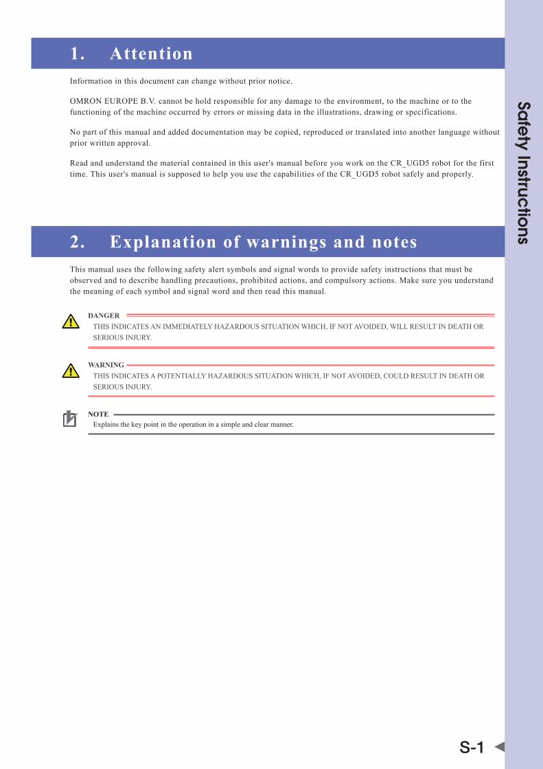
1. AttentionInformation in this document can change without prior notice.
OMRON EUROPE B.V. cannot be hold responsible for any damage to the environment, to the machine or to the functioning of the machine occurred by errors or missing data in the illustrations, drawing or specifications.
No part of this manual and added documentation may be copied, reproduced or translated into another language without prior written approval.
Read and understand the material contained in this user's manual before you work on the CR_UGD5 robot for the first time. This user's manual is supposed to help you use the capabilities of the CR_UGD5 robot safely and properly.
2. Explanation of warnings and notesThis manual uses the following safety alert symbols and signal words to provide safety instructions that must be observed and to describe handling precautions, prohibited actions, and compulsory actions. Make sure you understand the meaning of each symbol and signal word and then read this manual.
DANGER ThIS INDICATES AN IMMEDIATELy hAzARDOUS SITUATION whICh, If NOT AVOIDED, wILL RESULT IN DEATh OR SERIOUS INjURy.
WARNING ThIS INDICATES A POTENTIALLy hAzARDOUS SITUATION whICh, If NOT AVOIDED, COULD RESULT IN DEATh OR SERIOUS INjURy.
NOTE Explains the key point in the operation in a simple and clear manner.
Sa
fety Instruc
tions
S-2
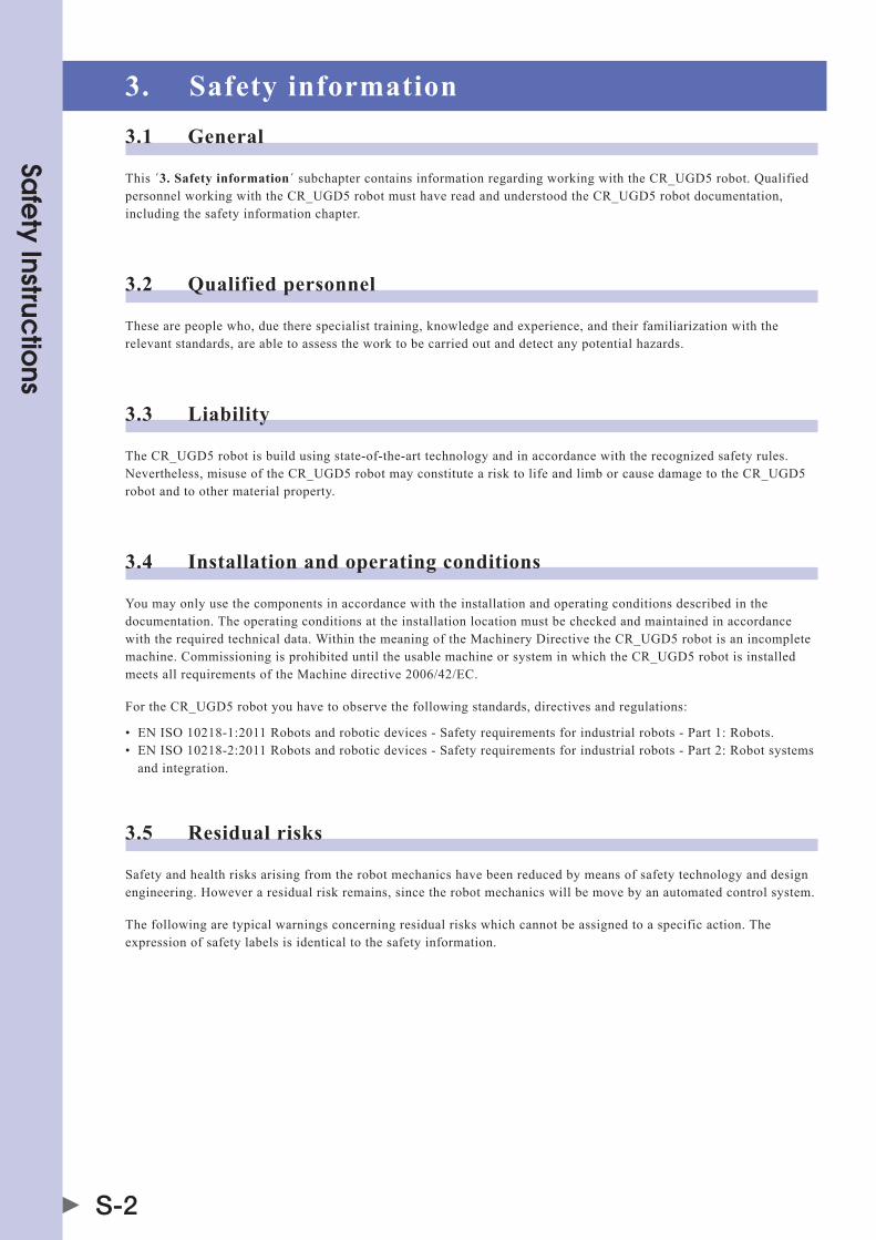
3. Safety information3.1 General
This ´3. Safety information´ subchapter contains information regarding working with the CR_UGD5 robot. Qualified personnel working with the CR_UGD5 robot must have read and understood the CR_UGD5 robot documentation, including the safety information chapter.
3.2 Qualified personnel
These are people who, due there specialist training, knowledge and experience, and their familiarization with the relevant standards, are able to assess the work to be carried out and detect any potential hazards.
3.3 Liability
The CR_UGD5 robot is build using state-of-the-art technology and in accordance with the recognized safety rules. Nevertheless, misuse of the CR_UGD5 robot may constitute a risk to life and limb or cause damage to the CR_UGD5 robot and to other material property.
3.4 Installation and operating conditions
you may only use the components in accordance with the installation and operating conditions described in the documentation. The operating conditions at the installation location must be checked and maintained in accordance with the required technical data. within the meaning of the Machinery Directive the CR_UGD5 robot is an incomplete machine. Commissioning is prohibited until the usable machine or system in which the CR_UGD5 robot is installed meets all requirements of the Machine directive 2006/42/EC.
for the CR_UGD5 robot you have to observe the following standards, directives and regulations:
• ENISO10218-1:2011Robotsandroboticdevices-Safetyrequirementsforindustrialrobots-Part1:Robots.• ENISO10218-2:2011Robotsandroboticdevices-Safetyrequirementsforindustrialrobots-Part2:Robotsystems and integration.
3.5 Residual risks
Safety and health risks arising from the robot mechanics have been reduced by means of safety technology and design engineering. however a residual risk remains, since the robot mechanics will be move by an automated control system.
The following are typical warnings concerning residual risks which cannot be assigned to a specific action. The expression of safety labels is identical to the safety information.
Sa
fety Instruc
tions
S-3
3.5.1 Release device
The robot mechanics are not supplied with an release switch to control the brakes of the motors.
WARNING • MOuNtaRElEaSESwItchONthEMachINESOthEaRMS(MOtOR)OfthERObOtcOuldbEMaNually MOVED. • MOvINgaNaxISwIthaNIMPROPERlywORkINgRElEaSESwItchcaNdaMagEthEMOtORbRakE.thIS CAN RESULT IN PERSONAL INjURy AND MATERIAL DAMAGE. • bEfORERElEaSINgthEbRakE,yOuhavEtObESuREthatNOONEISINthEhazaRdaREaOfthERObOt.
3.5.2 Transport
The prescribed transport position of the robot must be observed. Transportation must be carried out in accordance with the transportation instructions or assembly instructions of the robot.
WARNING • ONlyuSEauthORIzEdhaNdlINgEQuIPMENtwIthaSuffIcIENtlOad-bEaRINgcaPacItytOtRaNSPORt ThE ROBOT. • wEaRSuItablEPROtEctIvEclOthINgIfNEcESSaRy.
3.5.3 Assembly and start-up
Before starting up systems and devices for the first time, a check must be carried out to ensure that the system and devices are completed and operational, that they can be operated safely and that any damage is detected.
The valid national or regional work safety regulations must be observed for this check. The correct functioning of all safety circuits must also be tested.
The following tests must be carried out before start-up and recommissioning. It must be ensured that:
• therobotiscorrectlyinstalledandfastenedinaccordancewiththespecificationsintheassemblyinstructions.• therearenoforeignbodiesorloosepartsontherobot.• allrequiredsafetyequipmentiscorrectlyinstalledandoperational.
WARNING • awRONgINStallEdRObOtMaythROwOffhISaRMS. • wEaRSuItablEPROtEctIvEclOthINgIfNEcESSaRy.
3.5.4 Maintenance and repair
After maintenance and repair work, checks must be carried out to ensure the required safety level. The valid national or regional work safety regulations must be observed for this check. The correct functioning of all safety circuits must also be tested.
The purpose of maintenance and repair work is to ensure that the system is kept original or, in the event of a fault, to return the system to an operational state. Repair work includes troubleshooting in addition to the actual repair itself.
The following safety measures must be carried out when working on the robot:
• Switchofthemachine(system)wheretherobotisbuilt-in(e.g.withapadlock)topreventitfrombeingswitchedon again• labelthemachine(system)withasignindicationthatworkisinprogress.thissignmustremaininplace,even during temporary interruptions to the work.• theemergencystopfromthemachine(system)mustremainactive.Ifsafetyfunctionsorsafeguardsaredeactivated during maintenance or repair work, they must be reactivated immediately after the work is completed.

Sa
fety Instruc
tions
S-4
3.5.5 System integrator
The robot is safely integrated into a complete system by the system integrator. The system integrator is responsible for the following tasks:
• Installingtherobot• Performingriskassessment• Implementingtherequiredsafetyfunctionsandsafequards• Issuingthedeclarationofconformity• attachingthecEmark• creatingtheoperatinginstructionsforthecompletesystem
Chapter 1 Introduction
Contents
1. Introduction 1-11.1 Description of the robot 1-1
1.2 Type code explanation 1-1
2. Identification 1-1
3. Part names 1-2

1-1
1
Introd
uctio
n
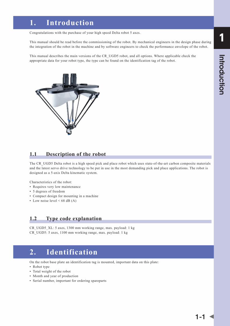
1. IntroductionCongratulations with the purchase of your high speed Delta robot 5 axes.
This manual should be read before the commissioning of the robot. By mechanical engineers in the design phase during the integration of the robot in the machine and by software engineers to check the performance envelope of the robot.
This manual describes the main versions of the CR_UGD5 robot, and all options. where applicable check the appropriate data for your robot type, the type can be found on the identification tag of the robot.
1.1 Description of the robotThe CR_UGD5 Delta robot is a high speed pick and place robot which uses state-of-the-art carbon composite materials and the latest servo drive technology to be put in use in the most demanding pick and place applications. The robot is designed as a 5-axis Delta kinematic system.
Characteristics of the robot:• Requiresverylowmaintenance• 5degreesoffreedom• compactdesignformountinginamachine• lownoiselevel<68db(a)
1.2 Type code explanationcR_ugd5_xl:5axes,1300mmworkingrange,max.payload:1kgCR_UGD5: 5 axes, 1100 mm working range, max. payload: 1 kg
2. IdentificationOn the robot base plate an identification tag is mounted, important data on this plate:• Robottype• totalweightoftherobot• Monthandyearofproduction• Serialnumber,importantfororderingspareparts
1-2
Introd
uctio
n
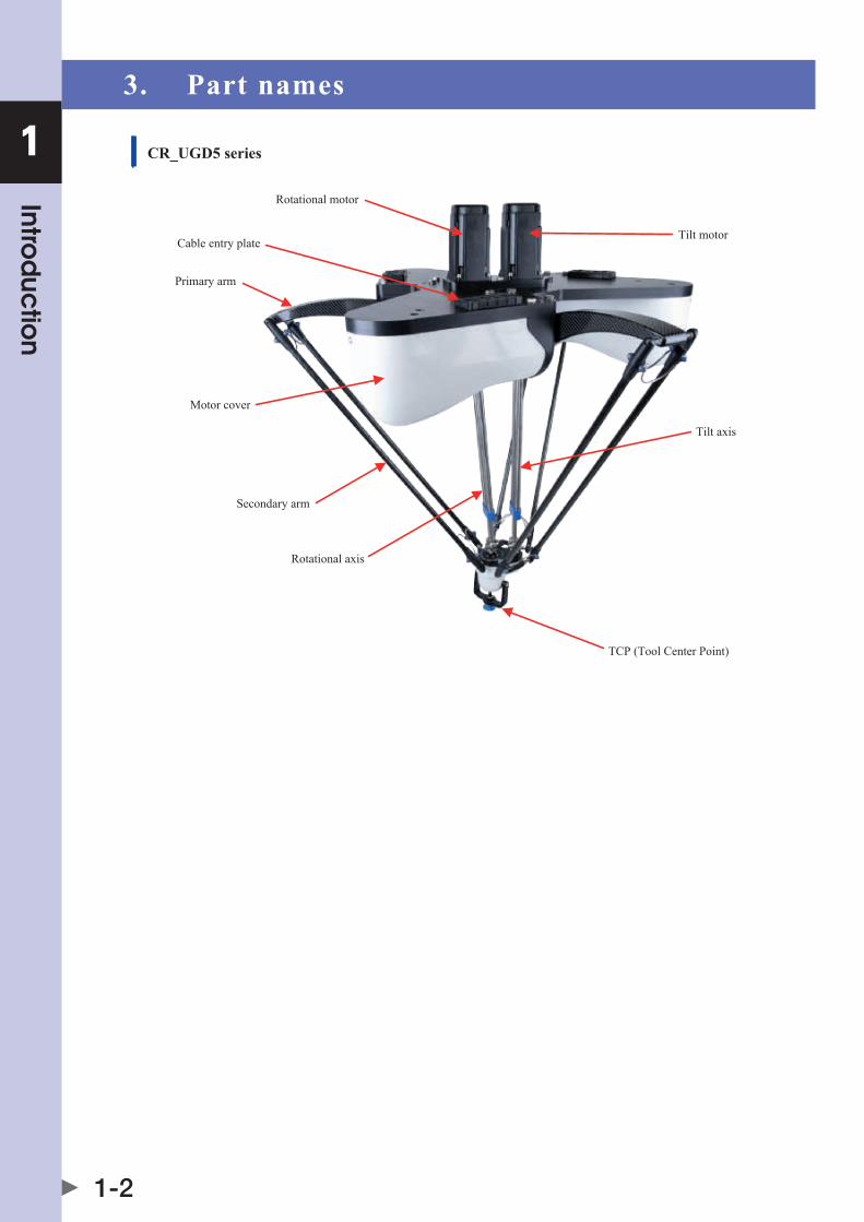
1 3. Part names
CR_UGD5 series
Primary arm
TCP (Tool Center Point)
Cable entry plateTilt motor
Motor cover
Secondary arm
Tilt axis
Rotational motor
Rotational axis

Chapter 2 Model overview
Contents
1. Overview 2-1

2
Mo
de
l overview
2-1
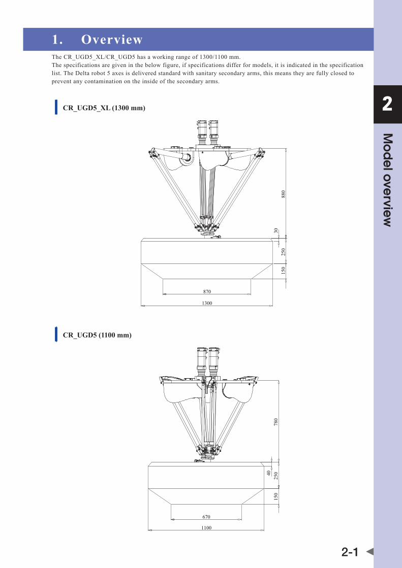
1. OverviewthecR_ugd5_xl/cR_ugd5hasaworkingrangeof1300/1100mm.The specifications are given in the below figure, if specifications differ for models, it is indicated in the specification list. The Delta robot 5 axes is delivered standard with sanitary secondary arms, this means they are fully closed to prevent any contamination on the inside of the secondary arms.
CR_UGD5_XL (1300 mm)
CR_UGD5 (1100 mm)
150
250
3088
0
870
1300
150
25040
780
670
1100


Chapter 3 Installation
Contents
1. Unpacking 3-11.1 Unpacking the shipping box 3-1
1.2 Check the damage 3-1
1.3 Lifting and transportation 3-1
2. Mounting the robot 3-3
3. Mounting the motors and cabling 3-43.1 Mounting the motors 3-4
3.2 Connecting the cables 3-4
3.3 Mounting the motor covers 3-5
3.4 Mounting the rotational and tilt gearbox with their adaptor plate 3-6
4. Assembling the secondary arms 3-74.1 Make an assembly 3-7
4.2 Mount the arm assembly on the robot 3-8
5. Mounting the rotational and tilt axis on the gearbox shafts 3-9
6. Calibration 3-10

3
Installa
tion
3-1
1. Unpacking1.1 Unpacking the shipping boxThe robot comes in a special shipping box.
The following step must be carried out to remove the cover from the box:• unscrewthescrewsfromthecoverofthewoodenbox• Nowremovethecover
1.2 Check the damagefirst take out the individual components from the package and check that everything is complete according to the following list:• 1xrotationalaxisincludinghead• 1xtiltaxisincludinghead• 1xadaptorplatefortherotationalaxisgear• 1xadaptorplateforthetiltaxisgear• 6xsecondaryarms• 1xspringpackage(12xspring)
Check all the components and the robot for transportation damage.
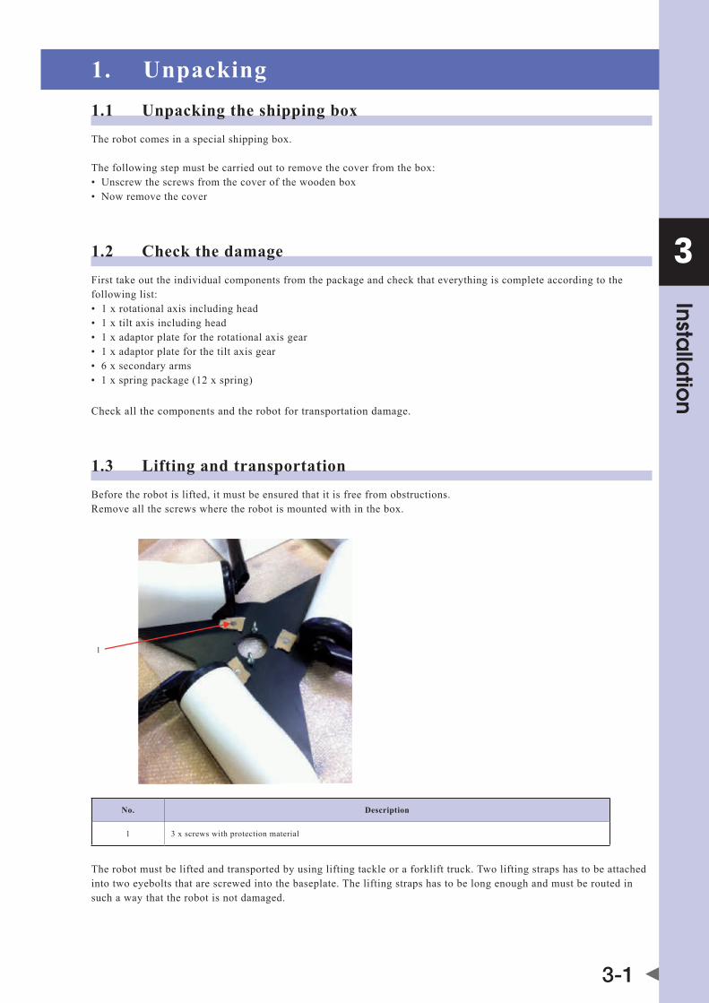
1.3 Lifting and transportationBefore the robot is lifted, it must be ensured that it is free from obstructions.Remove all the screws where the robot is mounted with in the box.
1
No. Description
1 3 x screws with protection material
The robot must be lifted and transported by using lifting tackle or a forklift truck. Two lifting straps has to be attached into two eyebolts that are screwed into the baseplate. The lifting straps has to be long enough and must be routed in such a way that the robot is not damaged.

3
Installa
tion
3-2
WARNING • thERObOtMaytIltduRINgtRaNSPORtatION. • addItIONalSafEguaRdINgMEaSuREMuStbEtakEN. • wEaRSuItablEPROtEctIvEclOthINgIfNEcESSaRy. • whENuSINgafORklIfttRuck,dRIvEExtREMElySlOwlyaNdcaREfully.
1
2
3
No. Description
1 Lifting tackle
2 2 x lifting straps
3 2 x eyebolts

3
Installa
tion
3-3
2. Mounting the robotThe mounting surface for the robot must be machined and of an appropriate quality. It’s also possible to use a levelling element to align the robot.Three M16 bolts are needed to mounting the robot to the frame, exact bolt length depends on frame layout. The tighteningtorqueofaM166.8boltis140Nm.
The below figure shows the mounting pattern from the robot.
3 x 120º mounting pattern
5º
120º
740
368,6
243
329,5 350,5
M16 (5x)
Rectangular shaped mounting pattern
NOTE It is advisable to put one motor of the robot in line with the direction of the transport belt to make programming easier.
3
Installa
tion
3-4
3. Mounting the motors and cabling3.1 Mounting the motorswhen your robot is delivered without motors, you have to mount them by yourself. first of all you have to remove the three motor covers from the robot.
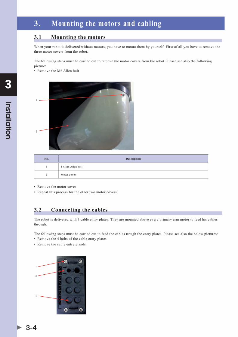
The following steps must be carried out to remove the motor covers from the robot. Please see also the following picture:• RemovetheM6allenbolt
1
2
No. Description
1 1 x M6 Allen bolt
2 Motor cover
• Removethemotorcover• Repeatthisprocessfortheothertwomotorcovers
3.2 Connecting the cablesThe robot is delivered with 3 cable entry plates. They are mounted above every primary arm motor to feed his cables through.
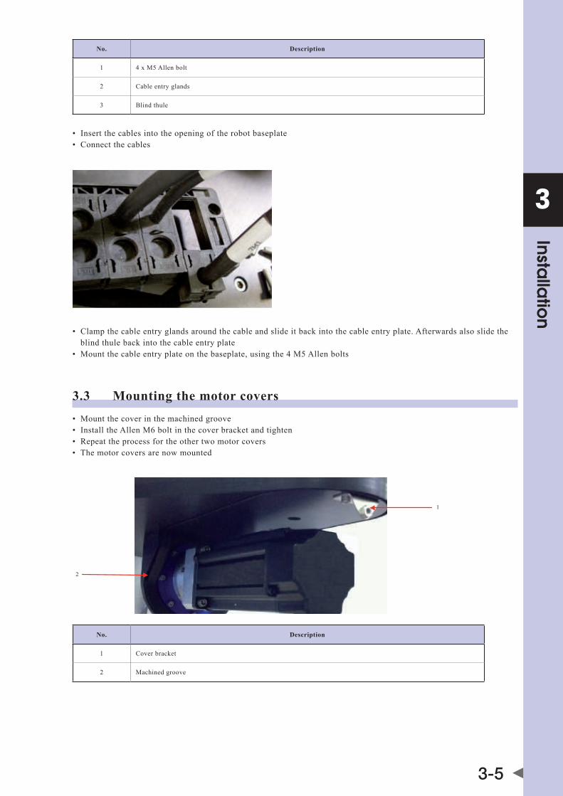
The following steps must be carried out to feed the cables trough the entry plates. Please see also the below pictures:• Removethe4boltsofthecableentryplates• Removethecableentryglands
1
2
3
3
Installa
tion
3-5
No. Description
1 4 x M5 Allen bolt
2 Cable entry glands
3 Blind thule
• Insertthecablesintotheopeningoftherobotbaseplate• connectthecables
• clampthecableentryglandsaroundthecableandslideitbackintothecableentryplate.afterwardsalsoslidethe blind thule back into the cable entry plate• Mountthecableentryplateonthebaseplate,usingthe4M5allenbolts
3.3 Mounting the motor covers• Mountthecoverinthemachinedgroove• InstalltheallenM6boltinthecoverbracketandtighten• Repeattheprocessfortheothertwomotorcovers• themotorcoversarenowmounted
2
1
No. Description
1 Cover bracket
2 Machined groove
3
Installa
tion
3-6
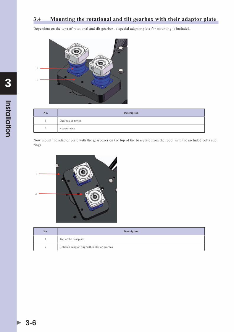
3.4 Mounting the rotational and tilt gearbox with their adaptor plateDependent on the type of rotational and tilt gearbox, a special adaptor plate for mounting is included.
1
2
No. Description
1 Gearbox or motor
2 Adaptor ring
Now mount the adaptor plate with the gearboxes on the top of the baseplate from the robot with the included bolts and rings.
1
2
No. Description
1 Top of the baseplate
2 Rotation adaptor ring with motor or gearbox
3
Installa
tion
3-7
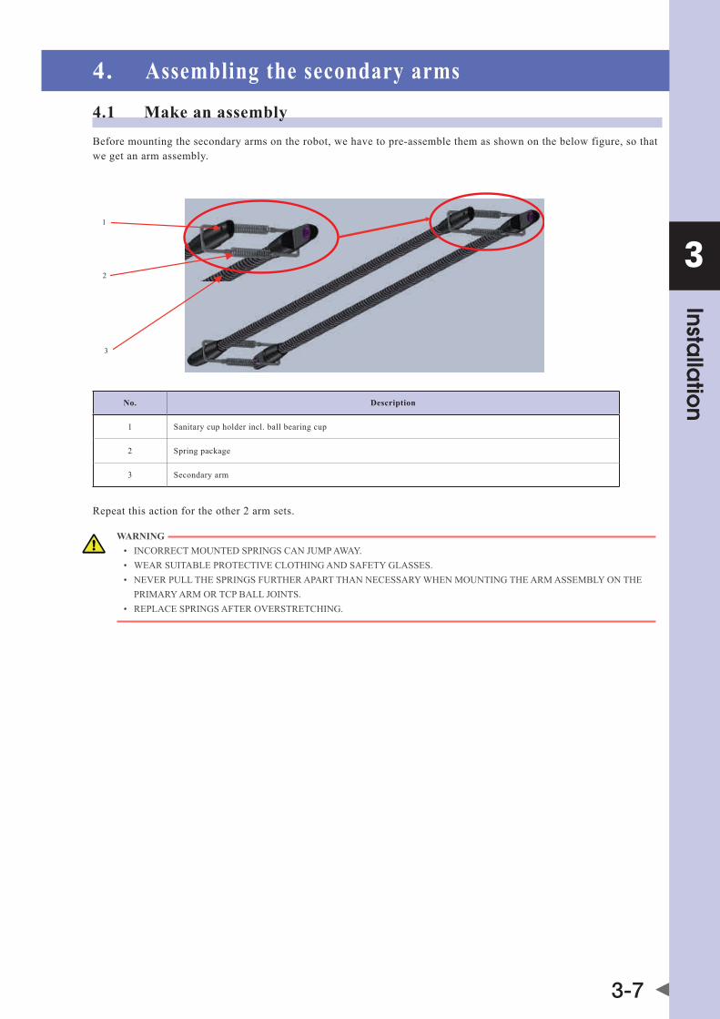
4. Assembling the secondary arms4.1 Make an assemblyBefore mounting the secondary arms on the robot, we have to pre-assemble them as shown on the below figure, so that we get an arm assembly.
1
2
3
No. Description
1 Sanitary cup holder incl. ball bearing cup
2 Spring package
3 Secondary arm
Repeat this action for the other 2 arm sets.
WARNING • INcORREctMOuNtEdSPRINgScaNjuMPaway. • wEaRSuItablEPROtEctIvEclOthINgaNdSafEtyglaSSES. • NEvERPullthESPRINgSfuRthERaPaRtthaNNEcESSaRywhENMOuNtINgthEaRMaSSEMblyONthE PRIMARy ARM OR TCP BALL jOINTS. • REPlacESPRINgSaftEROvERStREtchINg.

3
Installa
tion
3-8
4.2 Mount the arm assembly on the robotfor mounting, pull a secondary arm with his cup holder over the ball joint of the primary arm. Now pull the arms apart against the force of the spring in order to pull the second arm over the second ball joint of the primary arm.thenrepeatthisactionforthetcP(seebelowpicture).
1
No. Description
1 TCP - Tool Center Point
Repeat this action for the other 2 secondary arm assembly's.Now your robot mechanic is completely installed.
3
Installa
tion
3-9
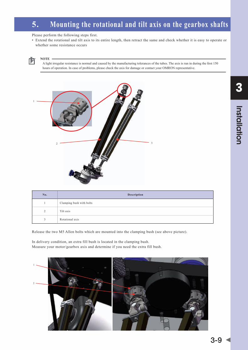
5. Mounting the rotational and tilt axis on the gearbox shaftsPlease perform the following steps first.• Extendtherotationalandtiltaxistoitsentirelength,thenretractthesameandcheckwhetheritiseasytooperateor whether some resistance occurs
NOTE alightirregularresistanceisnormalandcausedbythemanufacturingtolerancesofthetubes.theaxisisruninduringthefirst150hours of operation. In case of problems, please check the axis for damage or contact your OMRON representative.
1
2 3
No. Description
1 Clamping bush with bolts
2 Tilt axis
3 Rotational axis
ReleasethetwoM5allenboltswhicharemountedintotheclampingbush(seeabovepicture).
In delivery condition, an extra fill bush is located in the clamping bush.Measure your motor/gearbox axis and determine if you need the extra fill bush.
1
2
3
Installa
tion
3-10
No. Description
1 Motor or gear shaft
2 Top connector rotational axis
Now push the top connector into the shaft until the top connector comes into its stop position on the shaft. Tighten the two M5 Allen bolts with 7 Nm.
The rotational and tilt axis are now mounted.
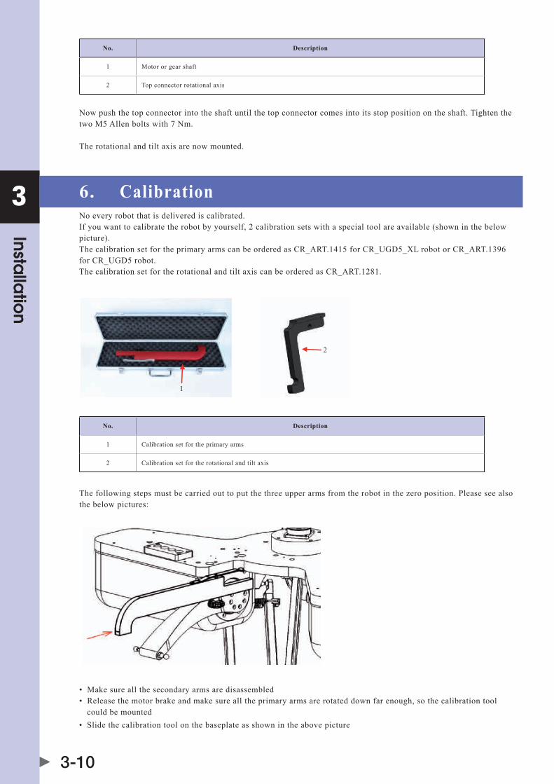
6. CalibrationNo every robot that is delivered is calibrated.Ifyouwanttocalibratetherobotbyyourself,2calibrationsetswithaspecialtoolareavailable(showninthebelowpicture).thecalibrationsetfortheprimaryarmscanbeorderedascR_aRt.1415forcR_ugd5_xlrobotorcR_aRt.1396for CR_UGD5 robot.thecalibrationsetfortherotationalandtiltaxiscanbeorderedascR_aRt.1281.
1
2
No. Description
1 Calibration set for the primary arms
2 Calibration set for the rotational and tilt axis
The following steps must be carried out to put the three upper arms from the robot in the zero position. Please see also the below pictures:
• Makesureallthesecondaryarmsaredisassembled• Releasethemotorbrakeandmakesurealltheprimaryarmsarerotateddownfarenough,sothecalibrationtool could be mounted• Slidethecalibrationtoolonthebaseplateasshownintheabovepicture

3
Installa
tion
3-11
• Nowtightenthestarnutuntilthetoolisfixed
• Releasethemotorbrakefromtheselectedmotorandpushtheupperarmwithhisballjointagainstthecalibration tool as shown in the above picture• Nowfixthemotorbrakefromtheselectedmotor• Repeatthecalibrationstepsfortheothertwoprimaryarms• Removethetool• Nowalltheprimaryarmsareinzeropositionfromthekinematicmodel• Nowputtheencodervaluesfromtheservomotorsin0°• checkthattheangleindicatedforthethreemotorsis0°(±0.1°)
The following steps must be carried out to put the rotational and tilt axis from the robot in the zero position. Please see also the below pictures:
• firstputtheswivelinthepositionasshownintheabovepicture.
3
Installa
tion
3-12
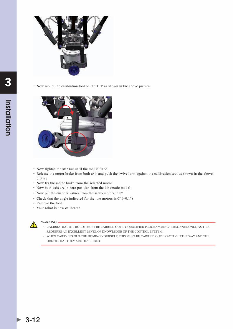
• NowmountthecalibrationtoolonthetcPasshownintheabovepicture.
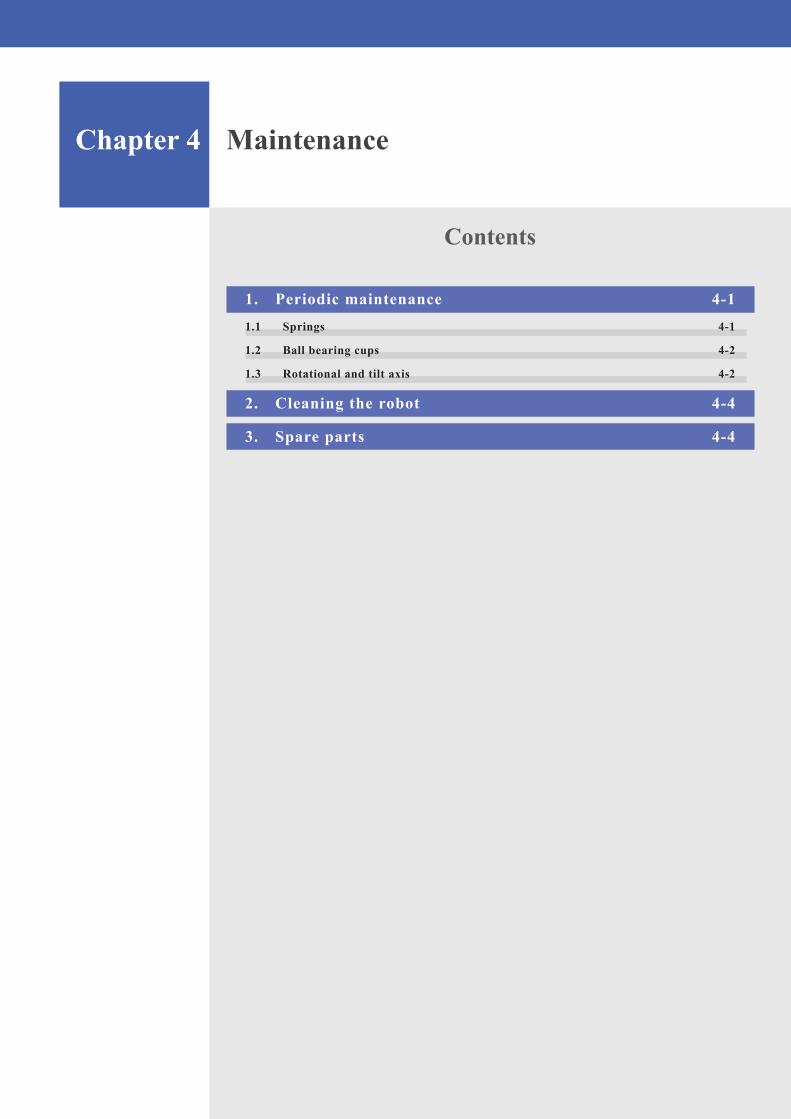
• Nowtightenthestarnutuntilthetoolisfixed• Releasethemotorbrakefrombothaxisandpushtheswivelarmagainstthecalibrationtoolasshownintheabove picture• Nowfixthemotorbrakefromtheselectedmotor• Nowbothaxisareinzeropositionfromthekinematicmodel• Nowputtheencodervaluesfromtheservomotorsin0°• checkthattheangleindicatedforthetwomotorsis0°(±0.1°)• Removethetool• yourrobotisnowcalibrated
WARNING • calIbRatINgthERObOtMuStbEcaRRIEdOutbyQualIfIEdPROgRaMMINgPERSONNElONly,aSthIS REQuIRESaNExcEllENtlEvElOfkNOwlEdgEOfthEcONtROlSyStEM. • whENcaRRyINgOutthEhOMINgyOuRSElf,thISMuStbEcaRRIEdOutExactlyINthEwayaNdthE ORDER ThAT ThEy ARE DESCRIBED.
Chapter 4 Maintenance
Contents
1. Periodic maintenance 4-11.1 Springs 4-1
1.2 Ball bearing cups 4-2
1.3 Rotational and tilt axis 4-2
2. Cleaning the robot 4-4
3. Spare parts 4-4

4
Ma
intena
nce
4-1
1. Periodic maintenanceBefore working on the robot, please be ensured that the machine where the robot is built in, is totally switched off.
DANGER • SwItchOffthEMachINE(SyStEM)whEREthERObOtISbuIltIN(E.g.wIthaPadlOck)tOPREvENtIt fROM BEING SwITChED ON AGAIN. • labElthEMachINE(SyStEM)wIthaSIgNINdIcatIONthatwORkISINPROgRESS.thISSIgNMuSt REMaININPlacE,EvENduRINgtEMPORaRyINtERRuPtIONStOthEwORk. • thEEMERgENcyStOPfROMthEMachINE(SyStEM)MuStREMaINactIvE.IfSafEtyfuNctIONSOR SafEguaRdSaREdEactIvatEdduRINgMaINtENaNcEORREPaIRwORk,thEyMuStbEREactIvatEd IMMEdIatElyaftERthEwORkIScOMPlEtEd.
1.1 Springshow to maintain the springs:• thespringshastobereplacedevery3800workinghoursoronceayear• whentherobotisfallapart,checkthespringsondamages• OnlyusespringsdeliveredbyOMRON,otherwisetheguaranteewillexpire• Replacespringsafteroverstretching• forspareparts,seeSection 3 Spare parts in this chapter
WARNING • INcORREctMOuNtEdSPRINgScaNjuMPaway. • wEaRSuItablEPROtEctIvEclOthINgaNdSafEtyglaSSES. • NEvERPullthESPRINgSfuRthERaPaRtthaNNEcESSaRywhENMOuNtINgthEaRMaSSEMblyONthE PRIMARy ARM OR TCP BALL jOINTS.
how to disassemble the springs:• disassemblethesecondaryarmsfromtherobot• Replacethesprings• forre-assemblingthesecondaryarms,seeSection 4 Assembling the secondary arms in Chapter 3
4
Ma
intena
nce
4-2
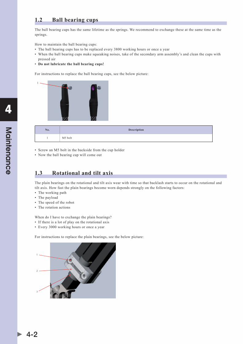
1.2 Ball bearing cupsThe ball bearing cups has the same lifetime as the springs. we recommend to exchange these at the same time as the springs.
how to maintain the ball bearing cups:• theballbearingcupshastobereplacedevery3800workinghoursoronceayear• whentheballbearingcupsmakesqueakingnoises,takeofthesecondaryarmassembly’sandcleanthecupswith pressed air• Do not lubricate the ball bearing cups!
for instructions to replace the ball bearing cups, see the below picture:
1
No. Description
1 M5 bolt
• ScrewanM5boltinthebacksidefromthecupholder• Nowtheballbearingcupwillcomeout
1.3 Rotational and tilt axisThe plain bearings on the rotational and tilt axis wear with time so that backlash starts to occur on the rotational and tilt axis. how fast the plain bearings become worn depends strongly on the following factors:• theworkingpath• thepayload• thespeedoftherobot• therotationactions
when do I have to exchange the plain bearings?• Ifthereisalotofplayontherotationalaxis• Every3000workinghoursoronceayear
for instructions to replace the plain bearings, see the below picture:
1
3
2
4
Ma
intena
nce
4-3
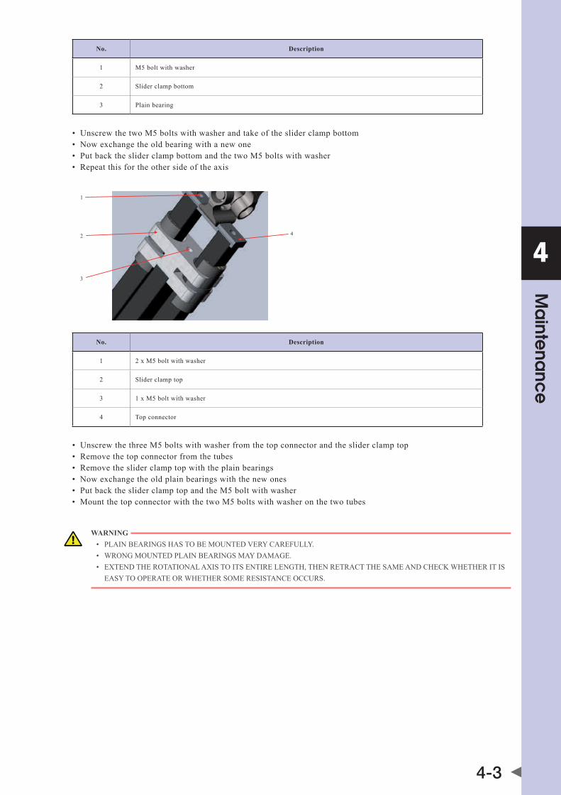
No. Description
1 M5 bolt with washer
2 Slider clamp bottom
3 Plain bearing
• unscrewthetwoM5boltswithwasherandtakeofthesliderclampbottom• Nowexchangetheoldbearingwithanewone• PutbackthesliderclampbottomandthetwoM5boltswithwasher• Repeatthisfortheothersideoftheaxis
1
3
2 4
No. Description
1 2 x M5 bolt with washer
2 Slider clamp top
3 1 x M5 bolt with washer
4 Top connector
• unscrewthethreeM5boltswithwasherfromthetopconnectorandthesliderclamptop• Removethetopconnectorfromthetubes• Removethesliderclamptopwiththeplainbearings• Nowexchangetheoldplainbearingswiththenewones• PutbackthesliderclamptopandtheM5boltwithwasher• MountthetopconnectorwiththetwoM5boltswithwasheronthetwotubes
WARNING • PlaINbEaRINgShaStObEMOuNtEdvERycaREfully. • wRONgMOuNtEdPlaINbEaRINgSMaydaMagE. • ExtENdthEROtatIONalaxIStOItSENtIRElENgth,thENREtRactthESaMEaNdchEckwhEthERItIS EASy TO OPERATE OR whEThER SOME RESISTANCE OCCURS.

4
Ma
intena
nce
4-4
2. Cleaning the robotClean the robot by washing with soft cloth or sponge. Use soap or mild detergent and warm water followed by clear water rinse.for oil and grease stains use alcohol with soft cloth.Do not use a high pressure water cleaner, or any other high pressure cleaning device.
3. Spare parts
DescriptionOMRON Part No.
CR_UGD5_XL CR_UGD5
Primary arm set 2 x ball bearing / 1 x dowel pin / 1 x primary arm CR_ART.1413 cR_aRt.1394
Ball bearing cups 12 x ball bearing cups cR_aRt.1395
Spring package 6 x spring / 12 x springholder CR_ART.1156
Secondary arm assembly 2 x spring / 4 x spring holder / 2 x secondary round arm CR_ART.1414 CR_ART.1157
Calibration set for the primary arms
1 x calibration tool / 1 x suitcase CR_ART.1415 cR_aRt.1396
Calibration set for the rotational and tilt axis
1 x calibration tool cR_aRt.1281
hinge rollers 24 x hinge rollers CR_ART.1325
Steel ball bearing package 6 x steel ball bearing cR_aRt.1398
Motor cover 1 x motor cover CR_ART.1236
Rotational axis 1 x complete rotational axis CR_ART.1417 cR_aRt.1399
Lower side rotational axis 1 x lower cardan and tube / 1 x TCP axis cR_aRt.1418 CR_ART.1400
Upper side rotational axis 1 x upper cardan / 1 x connection strip CR_ART.1401
Spline part rotational axis2 x square tube / 4 x plain bearing / 1 x connection strip / 4 x plastic blocks
cR_aRt.1419 CR_ART.1402
Rotary cover 1 x dome CR_ART.1403
Belt cover 1 x cover CR_ART.1404
fork 1 x fork CR_ART.1405
Gripperflange 1 x gripperflange CR_ART.1406
Plain bearing rotational axis
1 x plain bearing CR_ART.1020
Secondary arm1xcompletesecondaryarm(withoutspringsandbrackets)
CR_ART.1420 CR_ART.1407
Springs 6 x spring cR_aRt.1158
Chapter 5 Robot settings
Contents
1. Kinematics 5-1
2. Workspace 5-2
3. Software limits 5-3

5
Rob
ot se
ttings
5-1
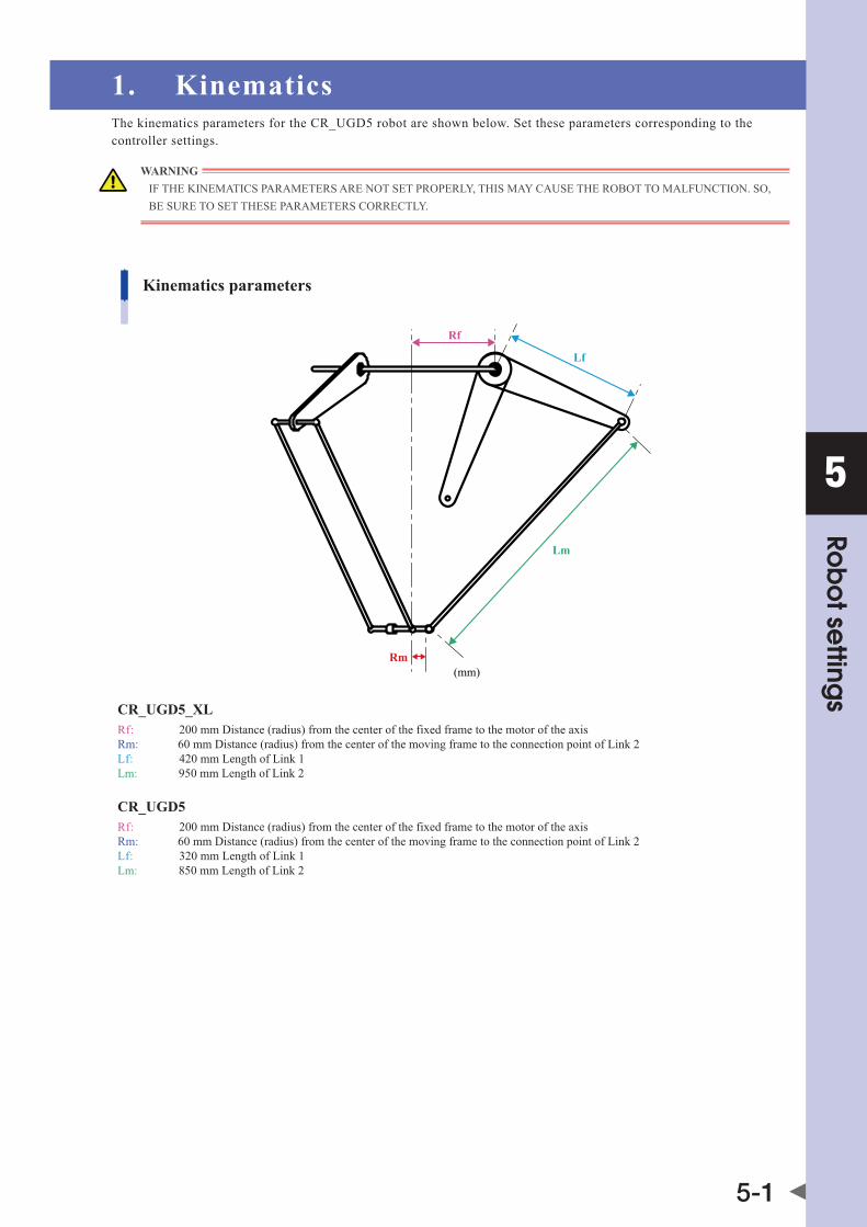
1. KinematicsThe kinematics parameters for the CR_UGD5 robot are shown below. Set these parameters corresponding to the controller settings.
WARNING IfthEkINEMatIcSPaRaMEtERSaRENOtSEtPROPERly,thISMaycauSEthERObOttOMalfuNctION.SO,BE SURE TO SET ThESE PARAMETERS CORRECTLy.
Lm
(mm)
Rf
Lf
Rm
Kinematics parameters
Rf: 200 mm Distance (radius) from the center of the fixed frame to the motor of the axisRm: 60 mm Distance (radius) from the center of the moving frame to the connection point of Link 2Lf: 420 mm Length of Link 1Lm: 950 mm Length of Link 2
CR_UGD5_XL
Rf: 200 mm Distance (radius) from the center of the fixed frame to the motor of the axisRm: 60 mm Distance (radius) from the center of the moving frame to the connection point of Link 2Lf: 320 mm Length of Link 1Lm: 850 mm Length of Link 2
CR_UGD5
5
Rob
ot se
ttings
5-2
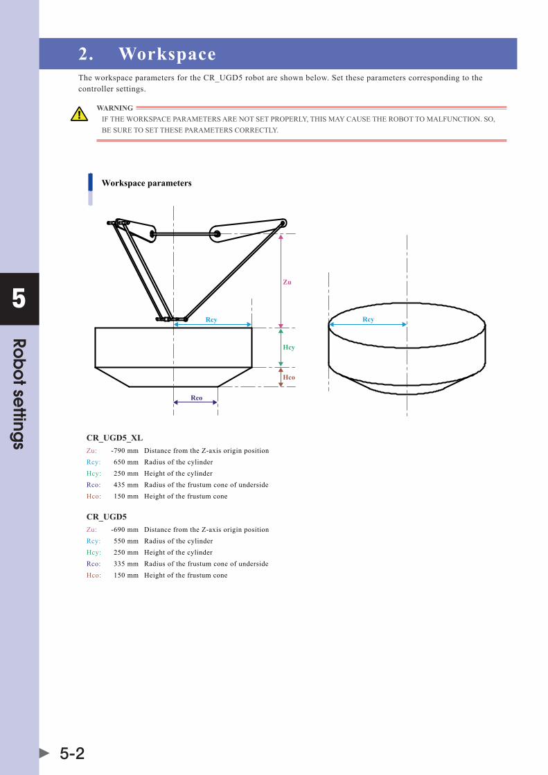
2. WorkspaceThe workspace parameters for the CR_UGD5 robot are shown below. Set these parameters corresponding to the controller settings.
WARNING IfthEwORkSPacEPaRaMEtERSaRENOtSEtPROPERly,thISMaycauSEthERObOttOMalfuNctION.SO,BE SURE TO SET ThESE PARAMETERS CORRECTLy.
Zu
Rcy
Hcy
Hco
Rcy
Rco
Workspace parameters
Zu: -790 mm Distance from the Z-axis origin position Rcy: 650 mm Radius of the cylinder Hcy: 250 mm Height of the cylinder Rco: 435 mm Radius of the frustum cone of underside Hco: 150 mm Height of the frustum cone
CR_UGD5_XL
Zu: -690 mm Distance from the Z-axis origin position Rcy: 550 mm Radius of the cylinder Hcy: 250 mm Height of the cylinder Rco: 335 mm Radius of the frustum cone of underside Hco: 150 mm Height of the frustum cone
CR_UGD5

5
Rob
ot se
ttings
5-3
3. Software limitsThe software limits for the CR_UGD5 robot are shown below.
WARNING If ThE α-, β- OR γ-axISSOftlIMItISSEtINcORREctly,thEaRMMaycOllIdEwIththERObOtbaSEORbaSEPREPaREdbythEuSER,cauSINgbREakagE.SO,bESuREtOSEtthESOftlIMItScORREctly.
Minus directionsoft limit [-35°]
Plus directionsoft limit [88°]

Chapter 6 Specifications
Contents
1. Basic specifications 6-11.1 Cycle time 6-1
2. External view and dimensions 6-22.1 CR_UGD5_XL 6-2
2.2 CR_UGD5 6-3
3. Design specifications 6-43.1 Occupation area of robot 6-4
3.2 Gripper interface 6-5
3.3 Software design 6-5
3.3.1 Dimensions and limits 6-63.3.2 Gear ratio 6-7
3.4 Recommended robot position 6-7

6
Spe
cific
atio
ns
6-1
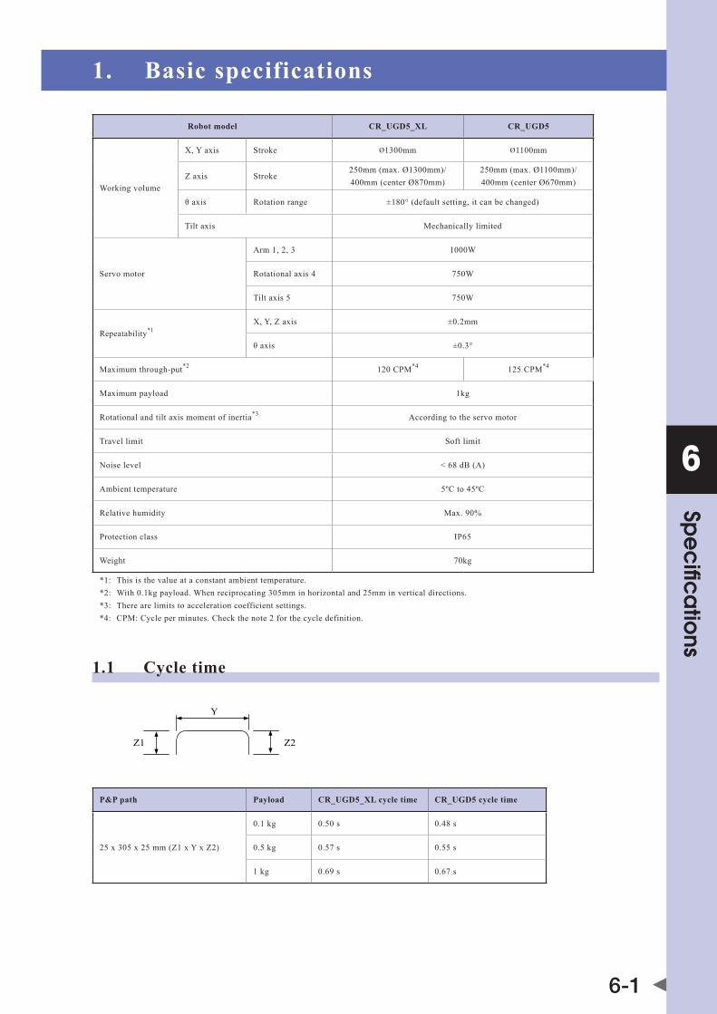
1. Basic specifications
Robot model CR_UGD5_XL CR_UGD5
working volume
x,yaxis Stroke Ø1300mm Ø1100mm
z axis Stroke250mm(max.Ø1300mm)/ 400mm(centerØ870mm)
250mm(max.Ø1100mm)/ 400mm(centerØ670mm)
θaxis Rotation range ±180°(defaultsetting,itcanbechanged)
Tilt axis Mechanically limited
Servo motor
Arm 1, 2, 3 1000w
Rotational axis 4 750w
Tilt axis 5 750w
Repeatability*1x,y,zaxis ±0.2mm
θaxis ±0.3°
Maximum through-put*2 120 CPM*4 125 CPM*4
Maximum payload 1kg
Rotational and tilt axis moment of inertia*3 According to the servo motor
Travel limit Soft limit
Noise level <68db(a)
Ambient temperature 5ºC to 45ºC
Relative humidity Max.90%
Protection class IP65
weight 70kg
*1: This is the value at a constant ambient temperature. *2: with 0.1kg payload. when reciprocating 305mm in horizontal and 25mm in vertical directions. *3: There are limits to acceleration coefficient settings. *4: CPM: Cycle per minutes. Check the note 2 for the cycle definition.
1.1 Cycle time
Z1
Y
Z2
P&P path Payload CR_UGD5_XL cycle time CR_UGD5 cycle time
25x305x25mm(z1xyxz2)
0.1 kg 0.50 s 0.48s
0.5 kg 0.57 s 0.55 s
1 kg 0.69s 0.67 s
6
Spe
cific
atio
ns
6-2
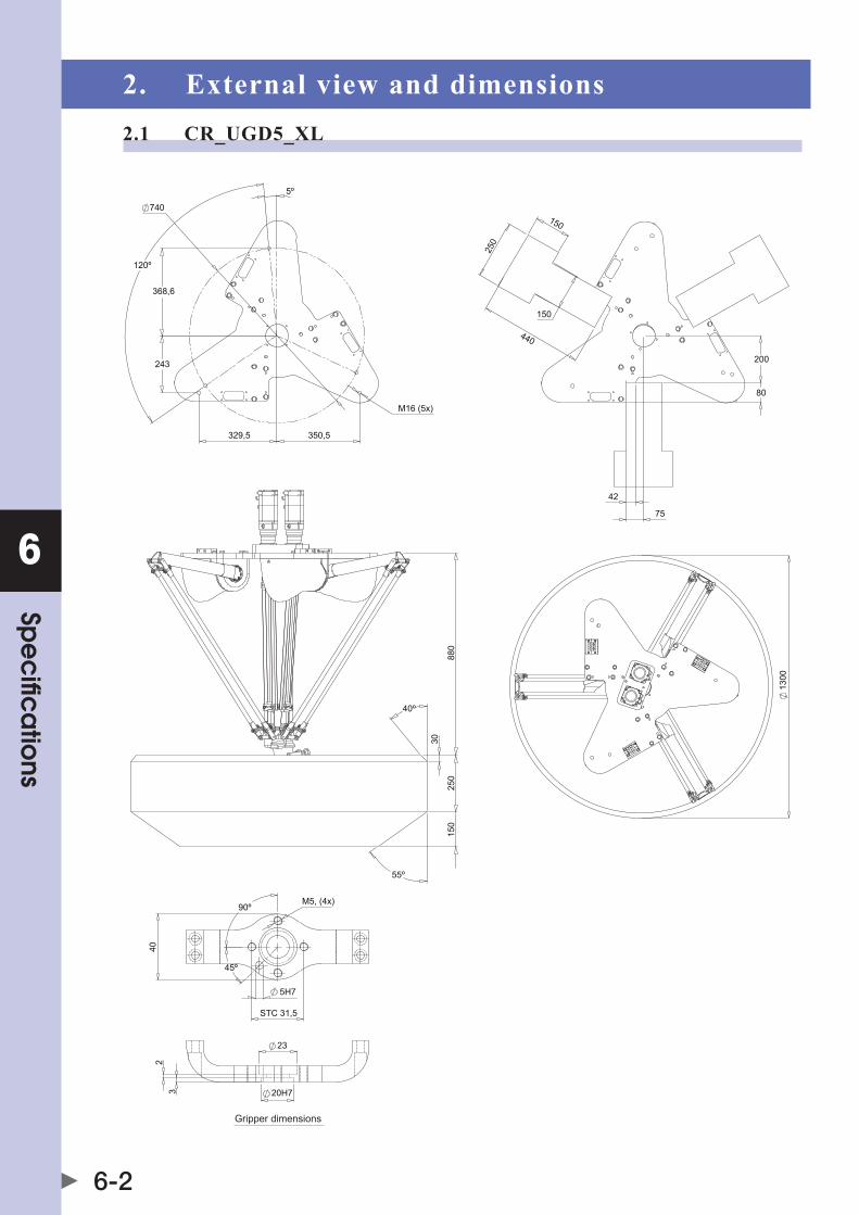
2. External view and dimensions2.1 CR_UGD5_XL

6
Spe
cific
atio
ns
6-3
2.2 CR_UGD5

6
Spe
cific
atio
ns
6-4
3. Design specifications3.1 Occupation area of robotIf the robot is integrated into the machine it must be considered what the reach is of all robot parts to prevent collision with other parts in the machine.
when the TCP moves to its outer positions, the primary and secondary arms can rise above the baseplate, take care that no mechanical obstructions are in the areas indicated in the below picture.
80
200
42
75
150
150
440
250
200
80
7542
150
130
335
350
CR_UGD5_XL
CR_UGD5
WARNING If MEChANICAL OBSTRUCTIONS ARE IN ThE INDICATED AREA, ThE ROBOT OR ThE OThER MAChINE PARTS COULD BE DAMAGED.
6
Spe
cific
atio
ns
6-5
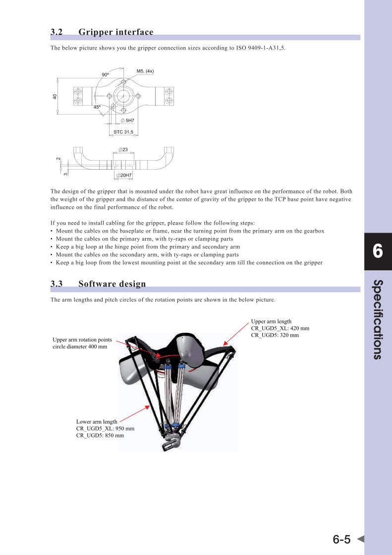
3.2 Gripper interfacethebelowpictureshowsyouthegripperconnectionsizesaccordingtoISO9409-1-a31,5.
5H7
STC 31,5
40
M5, (4x)90º
45º
23
23 20H7
The design of the gripper that is mounted under the robot have great influence on the performance of the robot. Both the weight of the gripper and the distance of the center of gravity of the gripper to the TCP base point have negative influence on the final performance of the robot.
If you need to install cabling for the gripper, please follow the following steps:• Mountthecablesonthebaseplateorframe,neartheturningpointfromtheprimaryarmonthegearbox• Mountthecablesontheprimaryarm,withty-rapsorclampingparts• keepabigloopatthehingepointfromtheprimaryandsecondaryarm• Mountthecablesonthesecondaryarm,withty-rapsorclampingparts• keepabigloopfromthelowestmountingpointatthesecondaryarmtilltheconnectiononthegripper
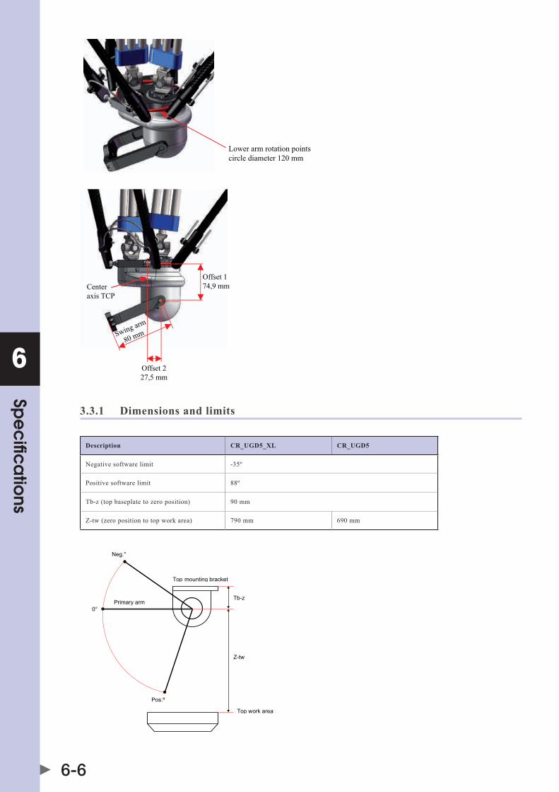
3.3 Software designThe arm lengths and pitch circles of the rotation points are shown in the below picture.
Upper arm lengthCR_UGD5_XL: 420 mmCR_UGD5: 320 mm
Lower arm lengthCR_UGD5_XL: 950 mmCR_UGD5: 850 mm
Upper arm rotation pointscircle diameter 400 mm
6
Spe
cific
atio
ns
6-6
Lower arm rotation pointscircle diameter 120 mm
Offset 174,9 mm
Offset 227,5 mm
Swing arm
80 mm
Centeraxis TCP
3.3.1 Dimensions and limits
Description CR_UGD5_XL CR_UGD5
Negative software limit -35º
Positive software limit 88º
tb-z(topbaseplatetozeroposition) 90mm
z-tw(zeropositiontotopworkarea) 790mm 690mm
Top mounting bracket
Top work area
Tb-z
Z-tw
0°
Pos.º
Neg.°
Primary arm

6
Spe
cific
atio
ns
6-7
3.3.2 Gear ratio
Description Ratio Comments
Rotational axis 4 1:2 Gear ratio achieved by a belt with pulleys.
Tilt axis 5 1:2therotationoftheswingarmislinkedtotheverticalrotation(rotationalaxis4).theswingarmrotateswitha ratio of 1:4 between the swing arm and the motor of rotational axis 4.
WARNING thEdIREctIONOfROtatIONOfthESwINgaRMdEPENdSONthEPOSItIONOfthEINtERNalgEaRbOx.thEREaREtwOPOSSIblEPOSItIONSfORthEgEaRbOx(ROtatEd180dEgREESfROMEachcONtROllER).thEPOSItIONOfthEgEaRbOxcaNNOtbEdEtERMINEdfROMthEINSIdEOROutSIdEOfthEStRuctuRE.thEPOSItIONhaStObEdEtERMINEdbyROtatINgtIltaxISwhENthERObOtIScOMPlEtElyINStallEd.PlEaSE,takENOtEthatthEPOSItIONOfthEgEaRbOxhaStObEREdEtERMINEdwhENthEROtatIONaxESaREdIScONNEctEdaNdthEcalIbRatIONISlOSt.
3.4 Recommended robot positionIt is recommended to place the robot in such way that there is no risk of the product or gripper hitting the lower arm of the robot in the situation where the swing arm is rotated to the horizontal position. This issue occurs due to the fact that the dome in which the swing arm is mounted isn't placed in the center of the TCP. Therefore the optimal position of the baseplate(intermsofrotation)isthepositionwherethereisthemostspacefortheswingarmtomovearound(whentheswingarmisplacedhorizontal).
Example: The optimal position of the base plate for the below situation is when the upper arm closest to tilt axis is placed closest and perpendicular to belt 2.
Belt 1 Belt 2(Swing armhorizontal)
(Swing arm vertical)Belt 1 Belt 2
(Swing armhorizontal
(Swing arm vertical)


Revision history
amanualrevisioncodeappearsasasuffixtothecatalognumberonthefrontcovermanual.
Cat. No. I205E-EN-01
Revision code
The following table outlines the changes made to the manual during each revision.
Revision code Date Description
01 October 2016 Original production

Cat. No. I205E-EN-01 Note: Specifications subject to change without notice.
Authorized Distributor:
Printed in Europe