Embed Size (px)
Citation preview
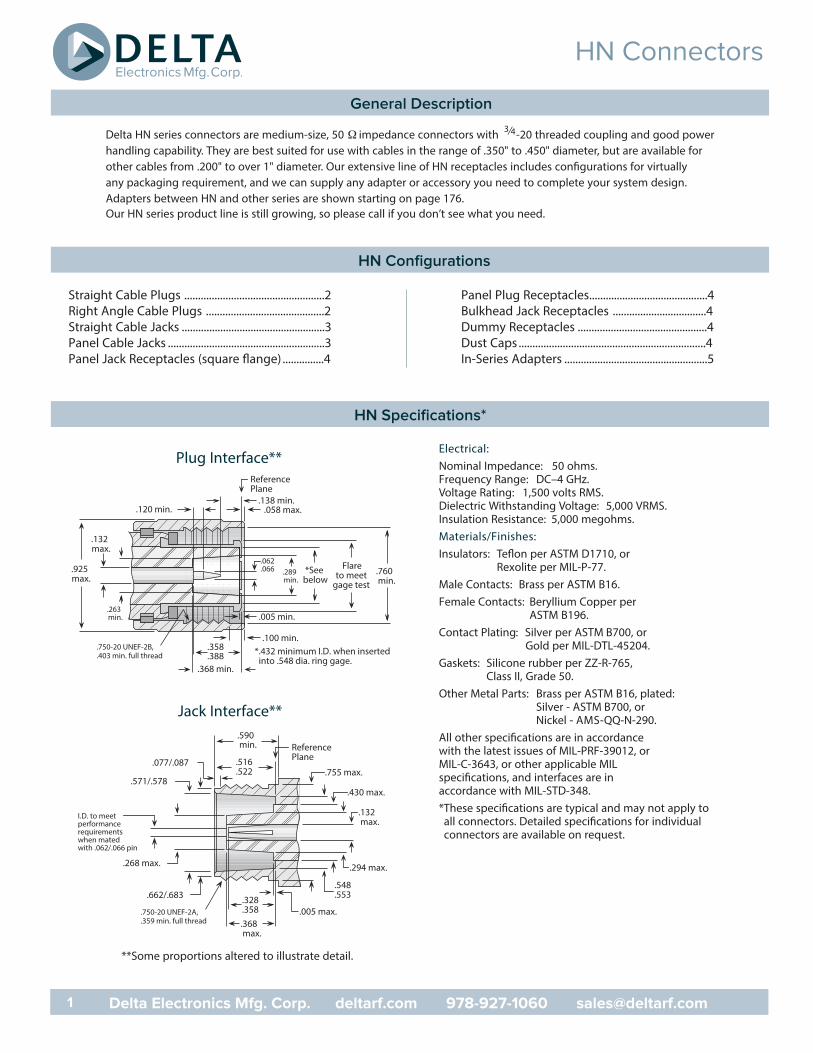
Delta HN series connectors are medium-size, 50 Ω impedance connectors with 3⁄4-20 threaded coupling and good powerhandling capability. They are best suited for use with cables in the range of .350" to .450" diameter, but are available forother cables from .200" to over 1" diameter. Our extensive line of HN receptacles includes configurations for virtuallyany packaging requirement, and we can supply any adapter or accessory you need to complete your system design.Adapters between HN and other series are shown starting on page 176.Our HN series product line is still growing, so please call if you don’t see what you need.
Straight Cable Plugs ...................................................2Right Angle Cable Plugs ...........................................2Straight Cable Jacks ....................................................3Panel Cable Jacks .........................................................3Panel Jack Receptacles (square flange) ...............4
Panel Plug Receptacles...........................................4Bulkhead Jack Receptacles ..................................4Dummy Receptacles ...............................................4Dust Caps ....................................................................4In-Series Adapters ....................................................5
Electrical:Nominal Impedance: 50 ohms.Frequency Range: DC–4 GHz.Voltage Rating: 1,500 volts RMS.Dielectric Withstanding Voltage: 5,000 VRMS.Insulation Resistance: 5,000 megohms.Materials/Finishes:Insulators: Teflon per ASTM D1710, or
Rexolite per MIL-P-77.Male Contacts: Brass per ASTM B16.Female Contacts: Beryllium Copper per
ASTM B196.Contact Plating: Silver per ASTM B700, or
Gold per MIL-DTL-45204.Gaskets: Silicone rubber per ZZ-R-765,
Class II, Grade 50.Other Metal Parts: Brass per ASTM B16, plated:
Silver - ASTM B700, orNickel - AMS-QQ-N-290.
All other specifications are in accordancewith the latest issues of MIL-PRF-39012, orMIL-C-3643, or other applicable MILspecifications, and interfaces are inaccordance with MIL-STD-348.*These specifications are typical and may not apply toall connectors. Detailed specifications for individualconnectors are available on request.
ReferencePlane
.058 max.
.005 min.
.100 min..358.388
.368 min.
.138 min..120 min.
.750-20 UNEF-2B,
.403 min. full thread
.760 min.
Flareto meet
gage test
*See below
*.432 minimum I.D. when inserted into .548 dia. ring gage.
.132 max.
.925 max.
.289 min.
.263 min.
.062
.066
Plug Interface**
.077/.087 .516.522
.328
.358.368 max.
.005 max.
.590 min.
.750-20 UNEF-2A,
.359 min. full thread
ReferencePlane
.755 max.
.430 max..571/.578
I.D. to meetperformancerequirementswhen matedwith .062/.066 pin
.132 max.
.548
.553.662/.683
.268 max. .294 max.
Jack Interface**
**Some proportions altered to illustrate detail.
HN Connectors
1 Delta Electronics Mfg. Corp. deltarf.com 978-927-1060 [email protected]
General Description
HN Configurations
HN Specifications*
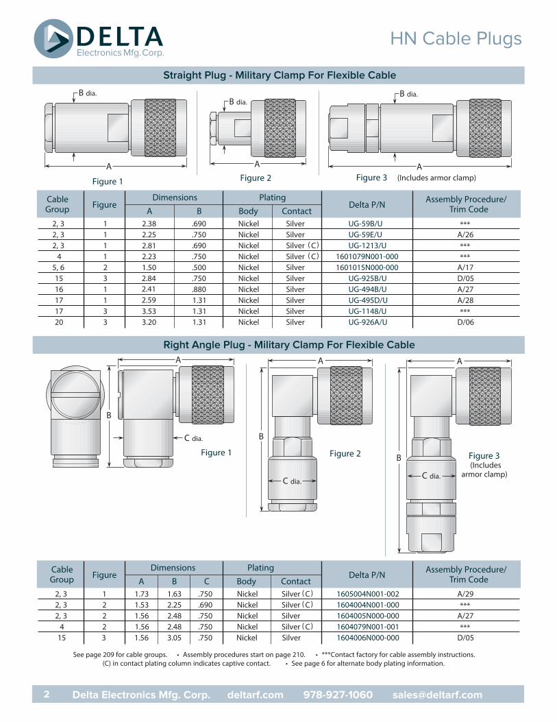
Cable FigureDimensions Plating
Delta P/N Assembly Procedure/Group A B Body Contact Trim Code
2, 3 1 2.38 .690 Nickel Silver UG-59B/U ***2, 3 1 2.25 .750 Nickel Silver UG-59E/U A/262, 3 1 2.81 .690 Nickel Silver ( C) UG-1213/U ***
4 1 2.23 .750 Nickel Silver ( C) 1601079N001-000 ***5, 6 2 1.50 .500 Nickel Silver 1601015N000-000 A/1715 3 2.84 .750 Nickel Silver UG-925B/U D/0516 1 2.41 .880 Nickel Silver UG-494B/U A/2717 1 2.59 1.31 Nickel Silver UG-495D/U A/2817 3 3.53 1.31 Nickel Silver UG-1148/U ***20 3 3.20 1.31 Nickel Silver UG-926A/U D/06
Figure 2Figure 1
A
B dia.
A
B dia.
A
B dia.
Figure 3 (Includes armor clamp)
Cable FigureDimensions Plating
Delta P/N Assembly Procedure/Group A B C Body Contact Trim Code
2, 3 1 1.73 1.63 .750 Nickel Silver ( C) 1605004N001-002 A/292, 3 2 1.53 2.25 .690 Nickel Silver ( C) 1604004N001-000 ***2, 3 2 1.56 2.48 .750 Nickel Silver 1604005N000-000 A/27
4 2 1.56 2.48 .750 Nickel Silver ( C) 1604079N001-001 ***15 3 1.56 3.05 .750 Nickel Silver 1604006N000-000 D/05
A
B
C dia.
A
B
C dia.
A
B
C dia.
Figure 3(Includes
armor clamp)
See page 209 for cable groups. • Assembly procedures start on page 210. • ***Contact factory for cable assembly instructions.(C) in contact plating column indicates captive contact. • See page 6 for alternate body plating information.
Figure 2Figure 1
HN Cable Plugs
2 Delta Electronics Mfg. Corp. deltarf.com 978-927-1060 [email protected]
Straight Plug - Military Clamp For Flexible Cable
Right Angle Plug - Military Clamp For Flexible Cable
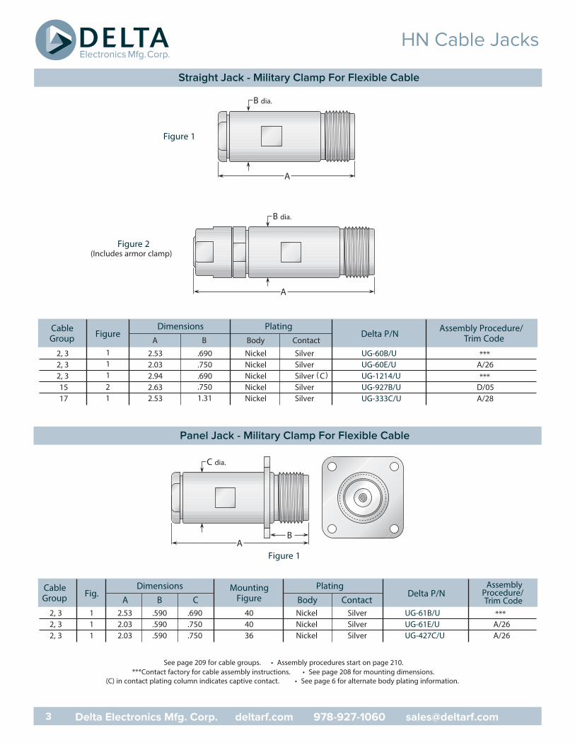
Figure 1A
B
C dia.
Cable Fig.Dimensions Mounting Plating
Delta P/NGroup A B C Figure
2, 3 1 2.53 .590 .690 40 UG-61B/U ***2, 3 1 2.03 .590 .750 40 UG-61E/U A/262, 3 1 2.03 .590 .750 36 UG-427C/U A/26
AssemblyProcedure/Trim Code
See page 209 for cable groups. • Assembly procedures start on page 210.***Contact factory for cable assembly instructions. • See page 208 for mounting dimensions.
(C) in contact plating column indicates captive contact. • See page 6 for alternate body plating information.
Cable FigureDimensions Plating
Delta P/N Assembly Procedure/Group Trim Code
UG-60B/U ***UG-60E/U A/26
( C) UG-1214/U ***15 2 2.63 .750 Nickel Silver UG-927B/U D/0517 1 UG-333C/U A/28
Figure 1
A
B dia.
A
B dia.
Figure 2(Includes armor clamp)
HN Cable Jacks
3 Delta Electronics Mfg. Corp. deltarf.com 978-927-1060 [email protected]
Straight Jack - Military Clamp For Flexible Cable
Panel Jack - Military Clamp For Flexible Cable
A B Body Contact
2, 3 1 2.53 .690 Nickel Silver2, 3 1 2.03 .750 Nickel Silver2, 3 1 2.94 .690 Nickel Silver
2.53 1.31 Nickel Silver
Body ContactNickel SilverNickel SilverNickel Silver
FigureDimensions Mounting Plating
Delta P/NA B C D Figure Body Contact
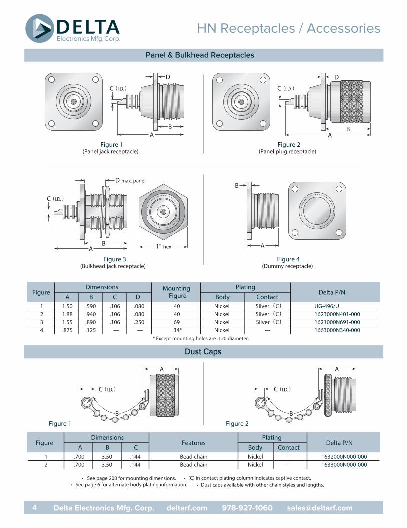
1 1.50 .590 .106 .080 40 Nickel Silver ( C) UG-496/U2 1.88 .940 .106 .080 40 Nickel Silver ( C) 1623000N401-0003 1.55 .890 .106 .250 69 Nickel Silver ( C) 1621000N691-0004 .875 .125 . — . — 34* Nickel — 1663000N340-000
Figure 1(Panel jack receptacle)
Figure 4(Dummy receptacle)
Figure 2(Panel plug receptacle)
Figure 1 Figure 2
C (I.D. )
AB
D
C (I.D. )
AB
D
A
B
Figure 3(Bulkhead jack receptacle)
1" hexAB
D max. panel
C (I.D. )
* Except mounting holes are .120 diameter.
A
B
C (I.D. )
A
B
C (I.D. )
FigureDimensions
FeaturesPlating
Delta P/NContactBodyCBA
1 .700 3.50 .144 Bead chain Nickel — 1632000N000-0002 .700 3.50 .144 Bead chain Nickel — 1633000N000-000
See page 208 for mounting dimensions. • (C) in contact plating column indicates captive contact.See page 6 for alternate body plating information. • Dust caps available with other chain styles and lengths.
HN Receptacles / Accessories
4 Delta Electronics Mfg. Corp. deltarf.com 978-927-1060 [email protected]
Panel & Bulkhead Receptacles
Dust Caps
••
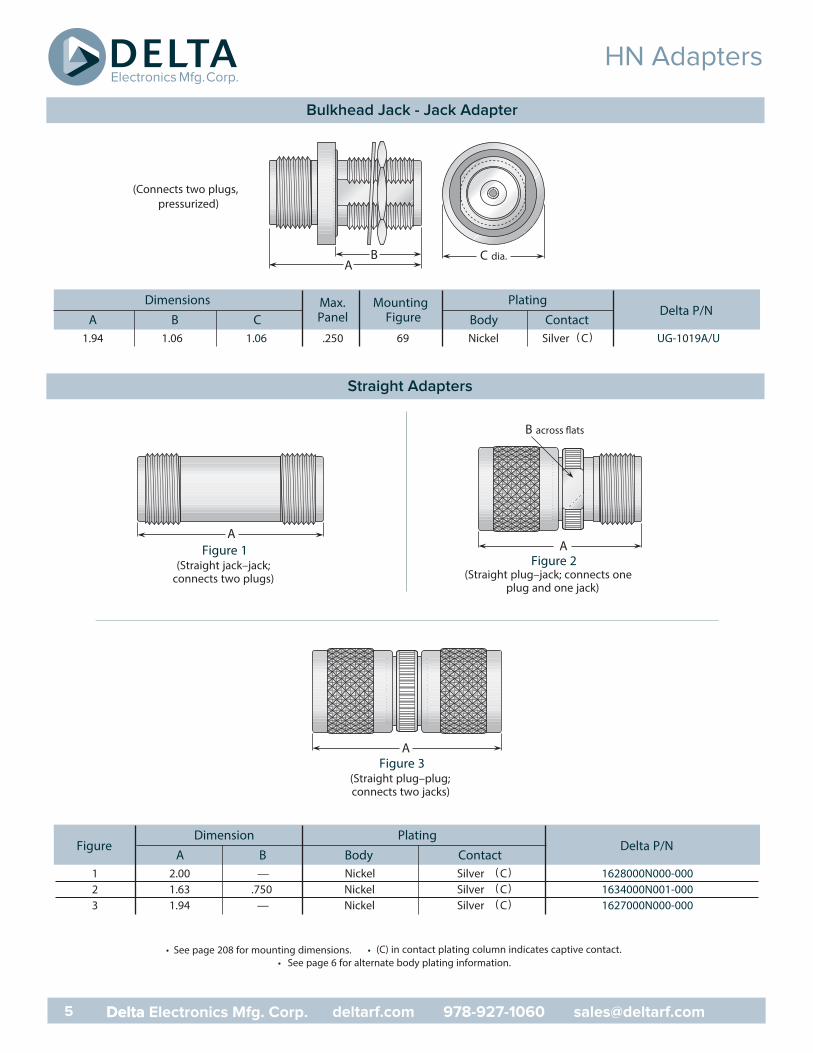
Dimensions Max. Mounting PlatingDelta P/N
A B C Panel Figure Body Contact1.94 1.06 .250 69 Nickel Silver ( C) UG-1019A/U
C dia.A
B
(Connects two plugs,pressurized)
See page 208 for mounting dimensions. • (C) in contact plating column indicates captive contact.See page 6 for alternate body plating information.
FigurePlatingDimension
Delta P/NA B Body Contact
1 2.00 .— Nickel Silver ( C) 1628000N000-0002 1.63 .750 Nickel Silver ( C) 1634000N001-0003 1.94 .— Nickel Silver ( C) 1627000N000-000
A
AA
B
Figure 1(Straight jack–jack;
connects two plugs)
Figure 3(Straight plug–plug;connects two jacks)
Figure 2(Straight plug–jack; connects one
plug and one jack)
HN Adapters
deltarf.com 978-927-1060 [email protected]
Bulkhead Jack - Jack Adapter
Straight Adapters
deltarf.com 978-927-1060 [email protected]
••
1.06
5 Delta Electronics Mfg. Corp.Delta
FigurePlatingDimensions
Delta P/NA B Body Contact
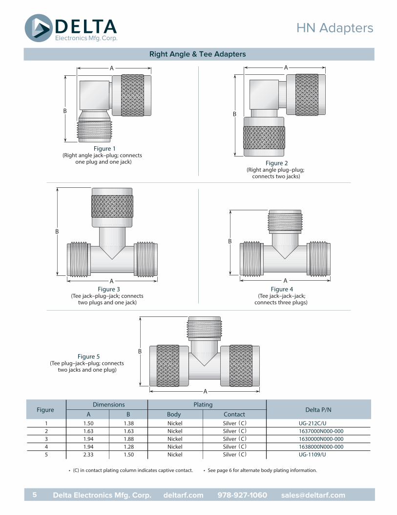
1 1.50 1.38 Nickel Silver ( C) UG-212C/U2 1.63 1.63 Nickel Silver ( C) 1637000N000-0003 1.94 1.88 Nickel Silver ( C) 1630000N000-0004 1.94 1.28 Nickel Silver ( C) 1638000N000-0005 2.33 1.50 Nickel Silver ( C) UG-1109/U
A
B
A
B
A
B
A
B
Figure 1(Right angle jack–plug; connects
one plug and one jack) Figure 2(Right angle plug–plug;
connects two jacks)
Figure 3(Tee jack–plug–jack; connects
two plugs and one jack)
Figure 4(Tee jack–jack–jack;
connects three plugs)
A
BFigure 5
(Tee plug–jack–plug; connectstwo jacks and one plug)
(C) in contact plating column indicates captive contact. • See page 6 for alternate body plating information.
HN Adapters
Right Angle & Tee Adapters
5 Delta Electronics Mfg. Corp. deltarf.com 978-927-1060 [email protected]
•
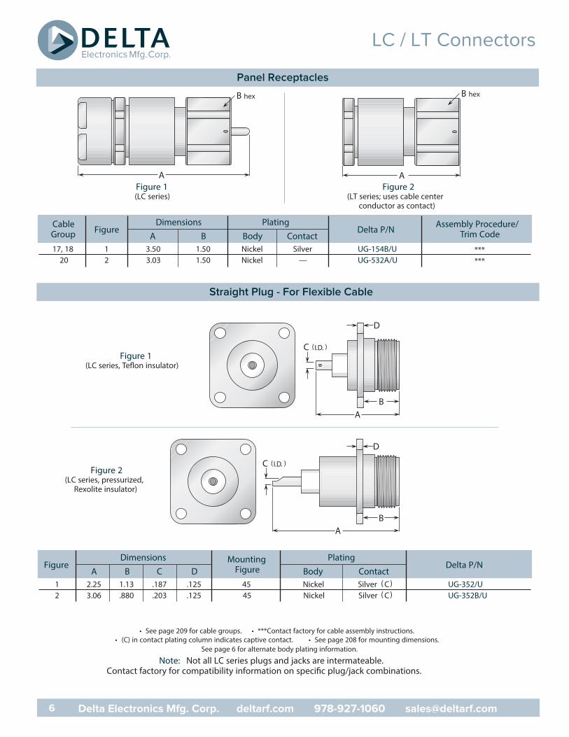
Cable FigureDimensions Plating
Delta P/N Assembly Procedure/Group A B Body Contact Trim Code
17, 18 1 3.50 1.50 Nickel Silver UG-154B/U ***20 2 3.03 1.50 Nickel — UG-532A/U ***
A
B hex
Figure 2(LT series; uses cable center
conductor as contact)
A
B hex
Figure 1(LC series)
FigureDimensions Mounting Plating
Delta P/NA B C D Figure Body Contact
1 2.25 1.13 .187 .125 45 Nickel Silver ( C) UG-352/U2 3.06 .880 .203 .125 45 Nickel Silver ( C) UG-352B/U
Figure 1(LC series, Teflon insulator)
Figure 2(LC series, pressurized,
Rexolite insulator)
AB
D
C (I.D. )
AB
D
C (I.D. )
See page 209 for cable groups. • ***Contact factory for cable assembly instructions.(C) in contact plating column indicates captive contact. • See page 208 for mounting dimensions.
See page 6 for alternate body plating information.
Note: Not all LC series plugs and jacks are intermateable.Contact factory for compatibility information on specific plug/jack combinations.
LC / LT Connectors
Panel Receptacles
6 Delta Electronics Mfg. Corp. deltarf.com 978-927-1060 [email protected]
Straight Plug - For Flexible Cable
••
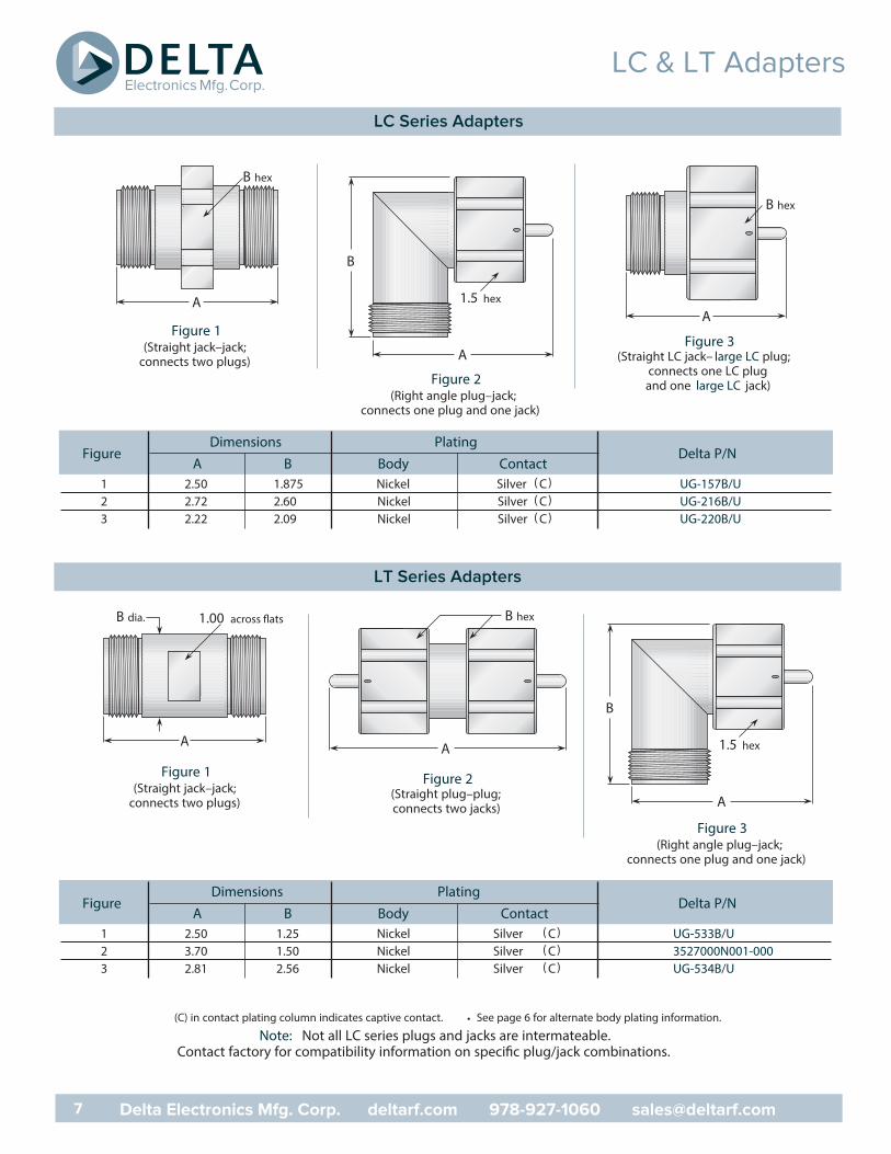
FigurePlatingDimensions
Delta P/NA B Body Contact
1 2.50 1.875 Nickel Silver ( C) UG-157B/U2 2.72 2.60 Nickel Silver ( C) UG-216B/U3 2.22 2.09 Nickel Silver ( C) UG-220B/U
A
B
1.5 hexA
B hex
A
B hex
Figure 1(Straight jack–jack;
connects two plugs)Figure 2
(Right angle plug–jack;connects one plug and one jack)
Figure 3(Straight LC jack– large LC plug;
connects one LC plugand one large LC jack)
FigurePlatingDimensions
Delta P/NA B Body Contact
1 2.50 1.25 Nickel Silver ( C) UG-533B/U2 3.70 1.50 Nickel Silver ( C) 3527000N001-0003 2.81 2.56 Nickel Silver ( C) UG-534B/U
A
B
1.5 hexA
1.00B dia.
A
B hex
Figure 1(Straight jack–jack;
connects two plugs)
Figure 3(Right angle plug–jack;
connects one plug and one jack)
Figure 2(Straight plug–plug;connects two jacks)
(C) in contact plating column indicates captive contact. • See page 6 for alternate body plating information.
Note: Not all LC series plugs and jacks are intermateable.Contact factory for compatibility information on specific plug/jack combinations.
LC & LT Adapters
LC Series Adapters
7 Delta Electronics Mfg. Corp. deltarf.com 978-927-1060 [email protected]
LT Series Adapters
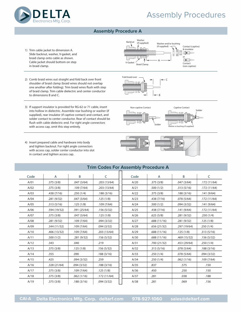
1) Trim cable jacket to dimension A. Slide backnut, washer, V-gasket, andbraid clamp onto cable as shown. Cable jacket should bottom on step in braid clamp.
2) Comb braid wires out straight and fold back over frontshoulder of braid clamp (braid wires should not overlapone another after folding). Trim braid wires flush with step of braid clamp. Trim cable dielectric and center conductor to dimensions B and C.
3) If support insulator is provided for RG-62 or 71 cable, insertinto hollow in dielectric. Assemble rear bushing or washer (ifsupplied), rear insulator (if captive contact) and contact, andsolder contact to center conductor. Rear of contact should beflush with cable dielectric end. For right angle connectorswith access cap, omit this step entirely.
4) Insert prepared cable and hardware into bodyand tighten backnut. For right angle connectorswith access cap, solder center conductor into slotin contact and tighten access cap.
Code A B C
A/01 .375 (3/8) .047 (3/64) .203 (13/64)
A/02 .375 (3/8) .109 (7/64) .203 (13/64)
A/03 .438 (7/16) .250 (1/4) .188 (3/16)
A/04 .281 (9/32) .047 (3/64) .125 (1/8)
A/05 .313 (5/16) .125 (1/8) .109 (7/64)
A/06 .594 (19/32) .391 (25/64) .156 (5/32)
A/07 .375 (3/8) .047 (3/64) .125 (1/8)
A/08 .281 (9/32) .109 (7/64) .094 (3/32)
A/09 .344 (11/32) .109 (7/64) .094 (3/32)
A/10 .406 (13/32) .109 (7/64) .203 (13/64)
A/11 .500 (1/2) .281 (9/32) .156 (5/32)
A/12 .343 .040 .219
A/13 .375 (3/8) .125 (1/8) .156 (5/32)
A/14 .355 .090 .188 (3/16)
A/15 .425 .094 (3/32) .259
A/16 .328 (21/64) .094 (3/32) .188 (3/16)
A/17 .375 (3/8) .109 (7/64) .125 (1/8)
A/18 .375 (3/8) .062 (1/16) .172 (11/64)
A/19 .375 (3/8) .188 (3/16) .094 (3/32)
Code A B C
A/20 .375 (3/8) .047 (3/64) .172 (11/64)
A/21 .500 (1/2) .313 (5/16) .172 (11/64)
A/22 .375 (3/8) .188 (3/16) .141 (9/64)
A/23 .438 (7/16) .078 (5/64) .172 (11/64)
A/24 .500 (1/2) .094 (3/32) .141 (9/64)
A/25 .438 (7/16) .141 (9/64) .172 (11/64)
A/26 .625 (5/8) .281 (9/32) .250 (1/4)
A/27 .688 (11/16) .281 (9/32) .125 (1/8)
A/28 .656 (21/32) .297 (19/64) .250 (1/4)
A/29 .688 (11/16) .125 (1/8) .313 (5/16)
A/30 .688 (11/16) .469 (15/32) .156 (5/32)
A/31 .700 (21/32) .453 (29/64) .250 (1/4)
A/32 .313 (5/16) .078 (5/64) .188 (3/16)
A/33 .250 (1/4) .078 (5/64) .094 (3/32)
A/34 .250 (1/4) .062 (1/16) .109 (7/64)
A/35 .837 .575 .150
A/36 .450 .250 .150
A/37 .281 .038 .188
A/38 .281 .069 .156
Assembly Procedures
Assembly Procedure A
CAI-A Delta Electronics Mfg. Corp. deltarf.com 978-927-1060 [email protected]
Trim Codes For Assembly Procedure A
BacknutWasher (if supplied)
V-GasketBraid Clamp
A
Washer and/or bushing(if supplied)
Contact(non-captive)
or
Contact (captive)& insulator
Fold braid over
B
C
Non-captive Contact
Solder
SolderCaptive Contact
Washer or bushing (if supplied)
Crimp Sleeve Contact (captive)
Contact(non-captive)
Solder
A
or
B C
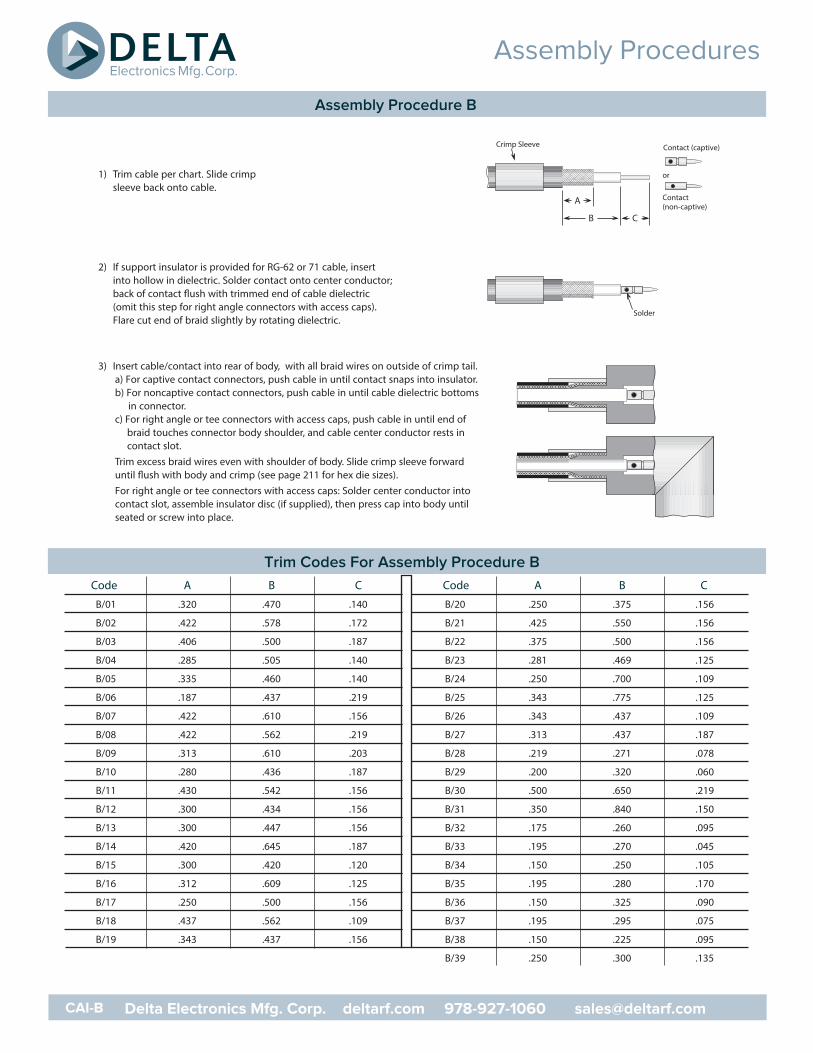
1) Trim cable per chart. Slide crimpsleeve back onto cable.
2) If support insulator is provided for RG-62 or 71 cable, insertinto hollow in dielectric. Solder contact onto center conductor;back of contact flush with trimmed end of cable dielectric(omit this step for right angle connectors with access caps).Flare cut end of braid slightly by rotating dielectric.
3) Insert cable/contact into rear of body, with all braid wires on outside of crimp tail. a) For captive contact connectors, push cable in until contact snaps into insulator. b) For noncaptive contact connectors, push cable in until cable dielectric bottoms
in connector.c) For right angle or tee connectors with access caps, push cable in until end of
braid touches connector body shoulder, and cable center conductor rests incontact slot.
Trim excess braid wires even with shoulder of body. Slide crimp sleeve forwarduntil flush with body and crimp (see page 211 for hex die sizes).For right angle or tee connectors with access caps: Solder center conductor intocontact slot, assemble insulator disc (if supplied), then press cap into body untilseated or screw into place.
Code A B C
B/01 .320 .470 .140
B/02 .422 .578 .172
B/03 .406 .500 .187
B/04 .285 .505 .140
B/05 .335 .460 .140
B/06 .187 .437 .219
B/07 .422 .610 .156
B/08 .422 .562 .219
B/09 .313 .610 .203
B/10 .280 .436 .187
B/11 .430 .542 .156
B/12 .300 .434 .156
B/13 .300 .447 .156
B/14 .420 .645 .187
B/15 .300 .420 .120
B/16 .312 .609 .125
B/17 .250 .500 .156
B/18 .437 .562 .109
B/19 .343 .437 .156
Code A B C
B/20 .250 .375 .156
B/21 .425 .550 .156
B/22 .375 .500 .156
B/23 .281 .469 .125
B/24 .250 .700 .109
B/25 .343 .775 .125
B/26 .343 .437 .109
B/27 .313 .437 .187
B/28 .219 .271 .078
B/29 .200 .320 .060
B/30 .500 .650 .219
B/31 .350 .840 .150
B/32 .175 .260 .095
B/33 .195 .270 .045
B/34 .150 .250 .105
B/35 .195 .280 .170
B/36 .150 .325 .090
B/37 .195 .295 .075
B/38 .150 .225 .095
B/39 .250 .300 .135
Assembly Procedures
Assembly Procedure B
CAI-B Delta Electronics Mfg. Corp. deltarf.com 978-927-1060 [email protected]
Trim Codes For Assembly Procedure B
Backnut Washer
GasketBraid Clamp
Contact (captive)& insulator
Contact(non-captive)
Fold braid over
Non-captive
Captive
Solder
A
B
C
or
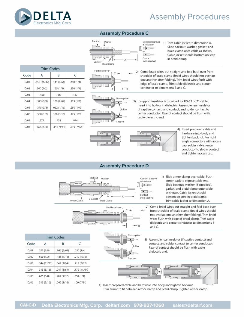
1) Trim cable jacket to dimension A. Slide backnut, washer, gasket, andbraid clamp onto cable as shown. Cable jacket should bottom on step in braid clamp.
2) Comb braid wires out straight and fold back over frontshoulder of braid clamp (braid wires should not overlapone another after folding). Trim braid wires flush withedge of braid clamp. Trim cable dielectric and center conductor to dimensions B and C.
3) If support insulator is provided for RG-62 or 71 cable,insert into hollow in dielectric. Assemble rear insulator (if captive contact) and contact, and solder contact to center conductor. Rear of contact should be flush with cable dielectric end.
4) Insert prepared cable andhardware into body andtighten backnut. For rightangle connectors with accesscap, solder cable center conductor to slot in contactand tighten access cap.
Trim Codes
Code A B C
C/01 .656 (21/32) .141 (9/64) .250 (1/4)
C/02 .500 (1/2) .125 (1/8) .250 (1/4)
C/03 .450 .136 .187
C/04 .375 (3/8) .109 (7/64) .125 (1/8)
C/05 .375 (3/8) .062 (1/16) .250 (1/4)
C/06 .500 (1/2) .188 (3/16) .125 (1/8)
C/07 .575 .438 .094
C/08 .625 (5/8) .141 (9/64) .219 (7/32)
V-Gasket
Backnut Washer
Braid Clamp
Contact (captive)& insulator
Contact(non-captive)
Fold braid over
A
B
C
or
Armor Clamp
Non-captive
Captive
Solder
1) Slide armor clamp over cable. Pusharmor back to expose cable end.Slide backnut, washer (if supplied),gasket, and braid clamp onto cableas shown. Cable jacket shouldbottom on step in braid clamp. Trim cable jacket to dimension A.
2) Comb braid wires out straight and fold back overfront shoulder of braid clamp (braid wires shouldnot overlap one another after folding). Trim braidwires flush with edge of braid clamp. Trim cabledielectric and center conductor to dimensions Band C.
3) Assemble rear insulator (if captive contact) andcontact, and solder contact to center conductor.Rear of contact should be flush with cabledielectric end.
4) Insert prepared cable and hardware into body and tighten backnut.Trim armor to fit between armor clamp and braid clamp. Tighten armor clamp.
Trim Codes
Code A B C
D/01 .375 (3/8) .047 (3/64) .250 (1/4)
D/02 .500 (1/2) .188 (3/16) .219 (7/32)
D/03 .344 (11/32) .047 (3/64) .219 (7/32)
D/04 .313 (5/16) .047 (3/64) .172 (11/64)
D/05 .625 (5/8) .281 (9/32) .250 (1/4)
D/06 .313 (5/16) .062 (1/16) .109 (7/64)
Assembly Procedures
Assembly Procedure C
CAI-C-D Delta Electronics Mfg. Corp. deltarf.com 978-927-1060 [email protected]
Assembly Procedure D
Backnut
Contact/Insulator/cone grip assembly
Solder
A
B
C
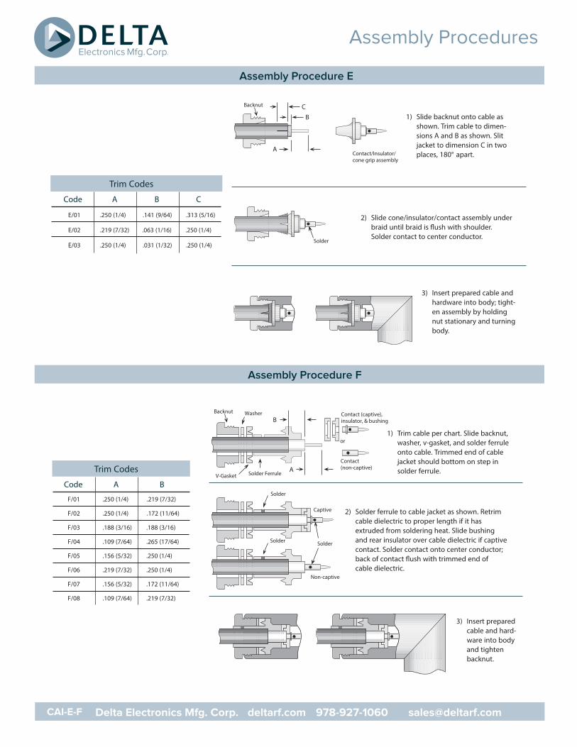
1) Slide backnut onto cable asshown. Trim cable to dimen-sions A and B as shown. Slitjacket to dimension C in twoplaces, 180° apart.
2) Slide cone/insulator/contact assembly underbraid until braid is flush with shoulder.Solder contact to center conductor.
3) Insert prepared cable andhardware into body; tight-en assembly by holdingnut stationary and turningbody.
Trim Codes
Code A B C
E/01 .250 (1/4) .141 (9/64) .313 (5/16)
E/02 .219 (7/32) .063 (1/16) .250 (1/4)
E/03 .250 (1/4) .031 (1/32) .250 (1/4)
Backnut Washer
V-Gasket Solder Ferrule
Contact (captive),insulator, & bushing
Contact(non-captive)
Non-captive
Captive
Solder
A
or
B
Solder
Solder
1) Trim cable per chart. Slide backnut,washer, v-gasket, and solder ferruleonto cable. Trimmed end of cablejacket should bottom on step in solder ferrule.
2) Solder ferrule to cable jacket as shown. Retrimcable dielectric to proper length if it hasextruded from soldering heat. Slide bushingand rear insulator over cable dielectric if captivecontact. Solder contact onto center conductor;back of contact flush with trimmed end ofcable dielectric.
Trim Codes
Code A B
F/01 .250 (1/4) .219 (7/32)
F/02 .250 (1/4) .172 (11/64)
F/03 .188 (3/16) .188 (3/16)
F/04 .109 (7/64) .265 (17/64)
F/05 .156 (5/32) .250 (1/4)
F/06 .219 (7/32) .250 (1/4)
F/07 .156 (5/32) .172 (11/64)
F/08 .109 (7/64) .219 (7/32)
3) Insert preparedcable and hard-ware into bodyand tightenbacknut.
Assembly Procedures
Assembly Procedure E
CAI-E-F Delta Electronics Mfg. Corp. deltarf.com 978-927-1060 [email protected]
Assembly Procedure F
with end of body
Soft solderall around
Coupling nutGasket‘C’ ringBody
B
A
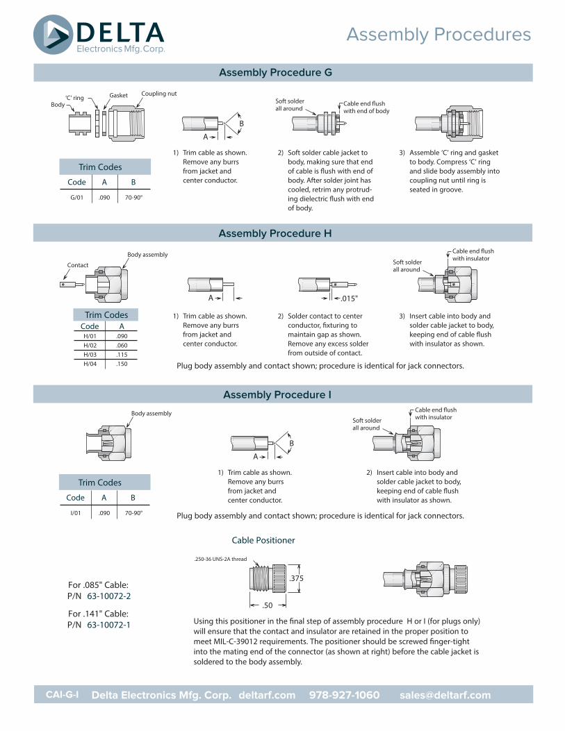
1) Trim cable as shown.Remove any burrsfrom jacket andcenter conductor.
2) Soft solder cable jacket tobody, making sure that endof cable is flush with end ofbody. After solder joint hascooled, retrim any protrud-ing dielectric flush with endof body.
3) Assemble ‘C’ ring and gasketto body. Compress ‘C’ ringand slide body assembly intocoupling nut until ring isseated in groove.
Trim Codes
Code A B
G/01 .090 70-90°
Trim CodesCode A
H/01 .090H/02 .060H/03 .115H/04 .150
with insulatorBody assembly
Contact
A .015"
Soft solderall around
1) Trim cable as shown.Remove any burrsfrom jacket andcenter conductor.
2) Solder contact to centerconductor, fixturing tomaintain gap as shown.Remove any excess solderfrom outside of contact.
3) Insert cable into body andsolder cable jacket to body,keeping end of cable flushwith insulator as shown.
Plug body assembly and contact shown; procedure is identical for jack connectors.
with insulatorBody assemblySoft solderall around
B
A
1) Trim cable as shown.Remove any burrsfrom jacket andcenter conductor.
2) Insert cable into body andsolder cable jacket to body,keeping end of cable flushwith insulator as shown.
Plug body assembly and contact shown; procedure is identical for jack connectors.
Trim Codes
Code A B
I/01 .090 70-90°
Cable Positioner
.50
.375
.250-36 UNS-2A thread
Using this positioner in the final step of assembly procedure H or I (for plugs only)will ensure that the contact and insulator are retained in the proper position tomeet MIL-C-39012 requirements. The positioner should be screwed finger-tightinto the mating end of the connector (as shown at right) before the cable jacket issoldered to the body assembly.
For .085" Cable:P/N 63-10072-2
For .141" Cable:P/N 63-10072-1
Assembly Procedures
Assembly Procedure G
CAI-G-I Delta Electronics Mfg. Corp. deltarf.com 978-927-1060 [email protected]
Assembly Procedure H
Assembly Procedure I
A
B
Soft solderall around
Solder centerconductor tocontact
Press cap inuntil seated
CapInsulator(if supplied)
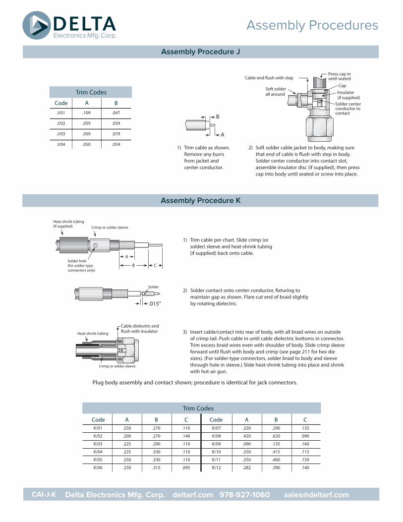
1) Trim cable as shown.Remove any burrsfrom jacket andcenter conductor.
2) Soft solder cable jacket to body, making surethat end of cable is flush with step in body.Solder center conductor into contact slot,assemble insulator disc (if supplied), then presscap into body until seated or screw into place.
Trim Codes
Code A B
J/01 .109 .047
J/02 .059 .039
J/03 .059 .079
J/04 .050 .059
Solder
.015"
Crimp or solder sleeve
Cable dielectric end
Heat-shrink tubing
Crimp or solder sleeve
Solder hole(for solder-typeconnectors only)
A
Heat-shrink tubing(if supplied)
B C
1) Trim cable per chart. Slide crimp (orsolder) sleeve and heat-shrink tubing(if supplied) back onto cable.
2) Solder contact onto center conductor, fixturing tomaintain gap as shown. Flare cut end of braid slightlyby rotating dielectric.
3) Insert cable/contact into rear of body, with all braid wires on outsideof crimp tail. Push cable in until cable dielectric bottoms in connector.Trim excess braid wires even with shoulder of body. Slide crimp sleeveforward until flush with body and crimp (see page 211 for hex diesizes). (For solder-type connectors, solder braid to body and sleevethrough hole in sleeve.) Slide heat-shrink tubing into place and shrinkwith hot-air gun.
Plug body assembly and contact shown; procedure is identical for jack connectors.
Code A B CK/01 .250 .270 .110
K/02 .200 .270 .140
K/03 .225 .290 .110
K/04 .225 .330 .110
K/05 .250 .330 .110
K/06 .250 .315 .095
Code A B CK/07 .220 .290 .135
K/08 .420 .620 .090
K/09 .090 .135 .160
K/10 .250 .415 .115
K/11 .250 .400 .150
K/12 .282 .390 .140
Trim Codes
Assembly Procedures
Assembly Procedure J
CAI-J-K Delta Electronics Mfg. Corp. deltarf.com 978-927-1060 [email protected]
Assembly Procedure K
Crimp or solder sleeve
Solder hole(for solder-type connectors)
AB C
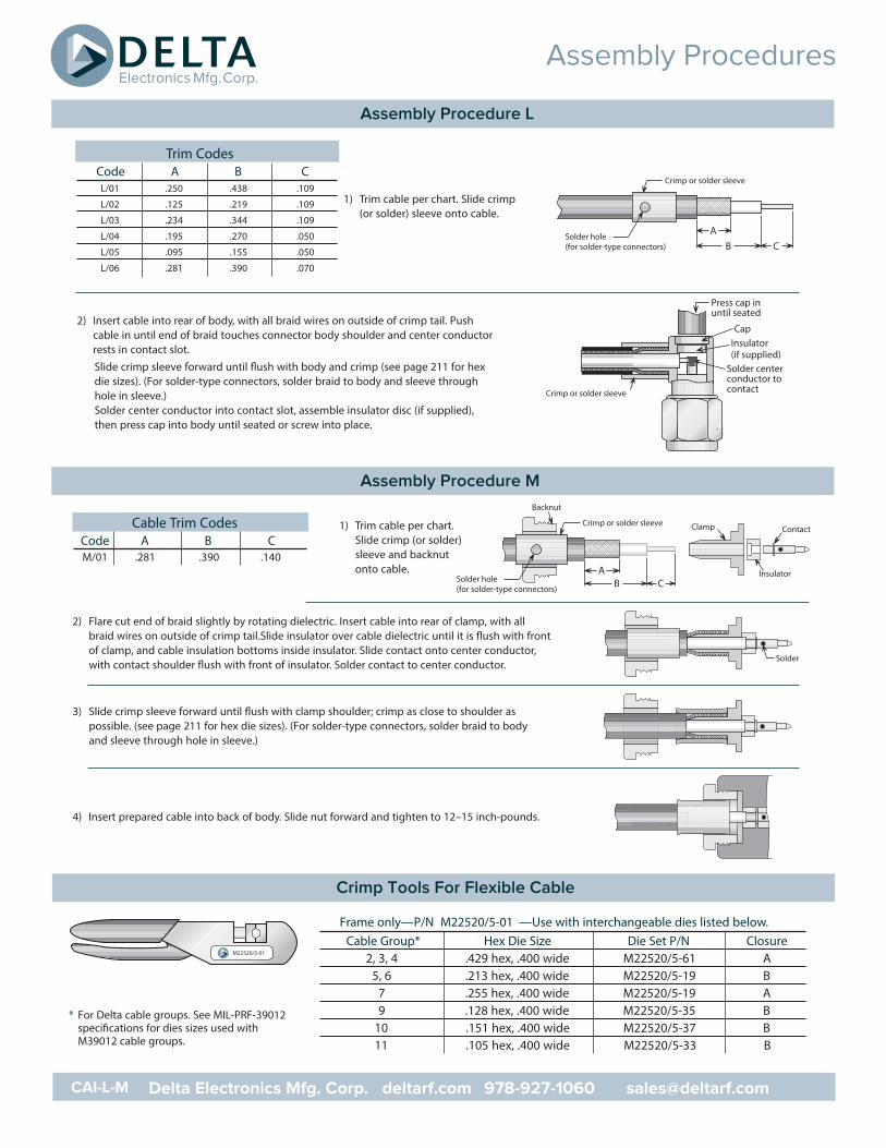
1) Trim cable per chart. Slide crimp (or solder) sleeve onto cable.
2) Insert cable into rear of body, with all braid wires on outside of crimp tail. Pushcable in until end of braid touches connector body shoulder and center conductorrests in contact slot.Slide crimp sleeve forward until flush with body and crimp (see page 211 for hexdie sizes). (For solder-type connectors, solder braid to body and sleeve throughhole in sleeve.) Solder center conductor into contact slot, assemble insulator disc (if supplied),then press cap into body until seated or screw into place.
Crimp or solder sleeve
Solder centerconductor tocontact
Press cap inuntil seated
CapInsulator(if supplied)
Backnut
Contact
Insulator
Clamp
AB C
Crimp or solder sleeve
Solder hole(for solder-type connectors)
Solder
1) Trim cable per chart.Slide crimp (or solder)sleeve and backnutonto cable.
2) Flare cut end of braid slightly by rotating dielectric. Insert cable into rear of clamp, with allbraid wires on outside of crimp tail.Slide insulator over cable dielectric until it is flush with frontof clamp, and cable insulation bottoms inside insulator. Slide contact onto center conductor,with contact shoulder flush with front of insulator. Solder contact to center conductor.
3) Slide crimp sleeve forward until flush with clamp shoulder; crimp as close to shoulder aspossible. (see page 211 for hex die sizes). (For solder-type connectors, solder braid to bodyand sleeve through hole in sleeve.)
4) Insert prepared cable into back of body. Slide nut forward and tighten to 12–15 inch-pounds.
Cable Trim CodesCode A B CM/01 .281 .390 .140
Frame only—P/N M22520/5-01 —Use with interchangeable dies listed below.Cable Group* Hex Die Size Die Set P/N Closure
2, 3, 4 .429 hex, .400 wide M22520/5-61 A5, 6 .213 hex, .400 wide M22520/5-19 B
7 .255 hex, .400 wide M22520/5-19 A9 .128 hex, .400 wide M22520/5-35 B
10 .151 hex, .400 wide M22520/5-37 B11 .105 hex, .400 wide M22520/5-33 B
M22520/5-01
Trim CodesCode A B CL/01 .250 .438 .109
L/02 .125 .219 .109
L/03 .234 .344 .109
L/04 .195 .270 .050
L/05 .095 .155 .050
L/06 .281 .390 .070
* For Delta cable groups. See MIL-PRF-39012specifications for dies sizes used withM39012 cable groups.
Assembly Procedures
Assembly Procedure L
CAI-L-M Delta Electronics Mfg. Corp. deltarf.com 978-927-1060 [email protected]
Assembly Procedure M
Crimp Tools For Flexible Cable
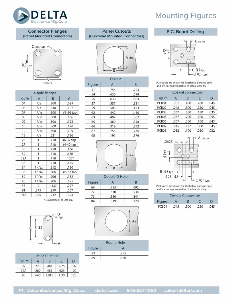
4-hole flangesFigure A B C
04 1/2 .360 .08905 1/2 .340 .10207 11/16 .500 #3-56 tap08 11/16 .500 .13609 11/16 .500 .12510 11/16 .500 .12012 11/16 .500 .10918 3/4 .531 .13626 1 .718 #6-32 tap27 1 .718 #4-40 tap30 1 .718 .16632 1 .718 .136
32A 1 .718 .136*33 1 .718 .12534 1 3/32 .812 .15036 1 3/16 .906 #6-32 tap39 1 3/16 .906 .15240 1 3/16 .906 .12545 2 1.437 .25791 .375 .250 .067
91A .375 .232 .093
Asquare
C dia. typ.
B(L) typ.C
A
D dia. typ.
B (L)CC
* Countersunk to .245 dia.
2-hole flangesFigure A B C D
92 .223 .481 .625 .10292A .260 .481 .625 .10295 .640 1.015 1.30 .125
D-HoleFigure A B
51 .755 .72354 .630 .59855 .630 .58357 .557 .53159 .505 .47362 .442 .41063 .407 .36265 .380 .34866 .319 .29267 .255 .23668 .195 .176
Double D-HoleFigure A B
69 .755 .69272 .630 .53675 .380 .34184 .319 .278
B
A dia.
B
A dia.
Round HoleFigure A
82 .25589 .380
A dia.
Twinax ConnectorsFigure A B C DPCB04 .045 .500 .250 .045
A dia. typ.
Ddia.
B (L) typ.CC (L) typ.C
A dia. typ.
.0625 typ.
Ddia.typ.
B (L) typ.C
C (L) typ.C.125 (L)C
Coaxial connectorsFigure A B C DPCB01 .067 .400 .200 .045PCB02 .045 .500 .250 .045PCB03 .067 .300 .150 .035PCB05 .067 .200 .100 .055PCB06 .067 .200 .100 .045PCB07 .045 .177 .088 .045PCB08 .032 .100 .050 .032
(PCB traces are shown for illustrative purpose only,and are not representative of actual circuitry.)
(PCB traces are shown for illustrative purpose only,and are not representative of actual circuitry.)
Mounting Figures
Connector Flanges(Panel Mounted Connectors)
A1 Delta Electronics Mfg. Corp. deltarf.com 978-927-1060 [email protected]
Panel Cutouts(Bulkhead Mounted Connectors)
P.C. Board Drilling
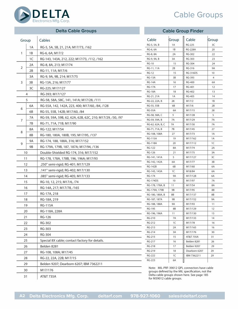
Group Cables
1A RG-5, 5A, 5B, 21, 21A; M17/73, /162
1 1B RG-6, 6A; M17/2
1C RG-143, 143A, 212, 222; M17/73, /112, /162
22A RG-8, 8A, 213; M17/74
2B RG-11, 11A; M17/6
3A RG-9, 9A, 9B, 214; M17/75
3 3B RG-13A, 216; M17/77
3C RG-225; M17/127
4 RG-393; M17/127
5 RG-58, 58A, 58C, 141, 141A; M17/28, /111
66A RG-55A, 142, 142A, 223, 400; M17/60, /84, /128
6B RG-55, 55B, 142B; M17/60, /84
77A RG-59, 59A, 59B, 62, 62A, 62B, 62C, 210; M17/29, /30, /97
7B RG-71, 71A, 71B; M17/90
88A RG-122; M17/54
8B RG-180, 180A, 180B, 195; M17/95, /137
99A RG-174, 188, 188A, 316; M17/152
9B RG-179A, 179B, 187, 187A; M17/94, /136
10 Double-Shielded RG-174, 316; M17/152
11 RG-178, 178A, 178B, 196, 196A; M17/93
12 .250" semi-rigid; RG-401; M17/129
13 .141" semi-rigid; RG-402; M17/130
14 .085" semi-rigid; RG-405; M17/133
15 RG-10, 12, 215; M17/6, /74
16 RG-14A, 217; M17/78, /165
17 RG-17A, 218
18 RG-18A, 219
19 RG-115A
20 RG-118A, 228A
21 RG-126
22 RG-302
23 RG-303
24 RG-304
25 Special 8X cable; contact factory for details.
26 Belden 8281
27 RG-108, 108A; M17/45
28 RG-22, 22A, 22B; M17/15
29 Belden 9207; Dearborn 6207; IBM 7362211
30 M17/176
31 AT&T 735A
Cable GroupRG-5, 5A, B 1A
RG-6, 6A 1B
RG-8, 8A 2A
RG-9, 9A, B 3A
RG-10 15
RG-11, 11A 2B
RG-12 15
RG-13A 3B
RG-14A 16
RG-17A 17
RG-18A 18
RG-21, 21A 1A
RG-22, 22A, B 28
RG-55, 55B 6B
RG-55A 6A
RG-58, 58A, C 5
RG-59, 59A, B 7A
RG-62, 62A, B, C 7A
RG-71, 71A, B 7B
RG-108, 108A 27
RG-115A 19
RG-118A 20
RG-122 8A
RG-126 21
RG-141, 141A 5
RG-142, 142A 6A
RG-142B 6B
RG-143, 143A 1C
RG-174 9A
RG-174DS 10
RG-178, 178A, B 11
RG-179A, 179B 9B
RG-180, 180A, B 8B
RG-187, 187A 9B
RG-188, 188A 9A
RG-195 8B
RG-196, 196A 11
RG-210 7A
RG-212 1C
RG-213 2A
RG-214 3A
RG-215 15
RG-217 16
RG-218 17
RG-219 18
RG-222 1C
RG-223 6A
Cable GroupRG-225 3C
RG-228A 20
RG-302 22
RG-303 23
RG-304 24
RG-316 9A
RG-316DS 10
RG-393 4
RG-400 6A
RG-401 12
RG-402 13
RG-405 14
M17/2 1B
M17/6 2B
M17/15 28
M17/28 5
M17/29 7A
M17/30 7A
M17/45 27
M17/73 1A
M17/162 1A
M17/112 1C
M17/74 2A
M17/75 3A
M17/127 3C
M17/77 3B
M17/60 6A
M18/84 6A
M17/128 6A
M17/97 7A
M17/54 8A
M17/95 8B
M17/137 8B
M17/152 9A
M17/93 11
M17/129 12
M17/130 13
M17/133 14
M17/78 16
M17/165 16
M17/176 30
AT&T 735A 31
Belden 8281 26
Belden 9207 29
Dearborn 6207 29
IBM 7362211 29
Note: MIL-PRF-39012 QPL connectors have cablegroups defined by the MIL specification, not the Delta cable groups shown here. See page 185 for M39012 cable groups.
Cable Groups
Delta Cable Groups
A2 Delta Electronics Mfg. Corp. deltarf.com 978-927-1060 [email protected]
Cable Group Finder

Delta Electronics Manufacturing Corporation416 Cabot Street, P.O. Box 53Beverly, MA 01915FSCM/CAGE 00795
Ordering & Warranty Information
A3 Delta Electronics Mfg. Corp. deltarf.com 978-927-1060 [email protected]
Warranty
We warrant our parts to be free of defects and workmanship for one year from purchase. During that time we will repair or replace (at our option) er’s, or military installation costs.
No other warranties apply, and no other liability may be assumed or extended by representatives or distributors. The terms of the applicable warranty or warranties, as the case may be, as set forth herein are the sole and exclusive warranty terms that shall have any any product order, resulting from the quotation and such terms and in lieu of all other warranties, expressed or implied, including the implied
Returns
Returns will be accepted only with a Return Authorization number issued by Delta, and are subject to inspection and acceptance upon arrival. Restocking charges will be determined prior to issusnce of Return Authorization. All claims for shortages must be made within 30 days of receipt by customer.
Ordering Information
or to sale. Order changes, cancellation, or termination will be accepted only with written approval from Delta Electronics Manufacturing.
Copyright, Trademarks, & Patents
Entire contents copyright 2017, Delta Electronics Manufacturing Corporation. Reproduction rights are hereby granted for, and spurchasing procedures,
by Delta customers only.
Heli-Grip® , PressMount® , and Global Manufacturer logo are trademarks. The Heli-Grip design is covered by U.S. and foreign patents.

Delta Electronics Mfg. Corp.
www.deltarf.com978-927-1060
PO Box 53416 Cabot St.
Beverly, MA 01915