Embed Size (px)
DESCRIPTION
DellCert - PowerConnect Training
Citation preview
1
Dell™ Dispatch Training for PowerConnect™ Switches
Contents Overview ....................................................................................................................................................... 3
Objectives.................................................................................................................................................. 3
The PowerConnect Range ......................................................................................................................... 3
Introduction .................................................................................................................................................. 4
Dell PowerConnect Advantages ................................................................................................................ 4
PowerConnect Naming Conventions ........................................................................................................ 4
The PowerConnect 2000 Models .............................................................................................................. 5
The PowerConnect 3000 Models .............................................................................................................. 5
The PowerConnect 5000 Models .............................................................................................................. 6
The PowerConnect 6000 Models .............................................................................................................. 6
Troubleshooting ............................................................................................................................................ 7
Basic Troubleshooting ............................................................................................................................... 7
“Lights Out” Troubleshooting ................................................................................................................... 7
Error Indication Troubleshooting .............................................................................................................. 8
Not Functioning as Required Troubleshooting ......................................................................................... 9
Not Functioning as Required – Verifying the Configuration ..................................................................... 9
Not Functioning as Required ‐ Stacking .................................................................................................. 10
Not Functioning as Required ‐ Features ................................................................................................. 10
Configuration Tips ................................................................................................................................... 11
Replacing a Switch ...................................................................................................................................... 11
Replacing a Switch – Non‐functioning Switch ......................................................................................... 11
Replacing a Switch – Functioning Switch ................................................................................................ 11
Setting up the Switch .................................................................................................................................. 12
Initial Setup – Managed Switches ........................................................................................................... 12
Initial Setup – Wizard or Manual? .......................................................................................................... 13
Configuring and Backing Up the Switch ...................................................................................................... 14
Initial Configuration – Manual Method .................................................................................................. 14
Backing Up Configurations ...................................................................................................................... 15

2
Restoring Configurations ........................................................................................................................ 15
Basic Functionality Test ........................................................................................................................... 16
Summary ..................................................................................................................................................... 16
Overvie
Objective
• This t
• At theooooooo
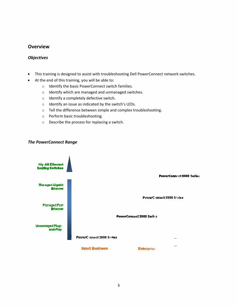
The Pow
ew
es
raining is des
e end of this t Identify th Identify wh Identify a c Identify an Tell the dif Perform b Describe t
werConnect R
signed to assis
training, you e basic Powehich are mancompletely dn issue as indifference betwasic troubleshhe process fo
Range
st with troub
will be able terConnect swaged and unmefective switcicated by the ween simple ahooting. or replacing a
3
leshooting De
o: itch families.managed switch. switch’s LEDand complex
switch.
ell PowerCon
tches.
s. troubleshoot
nect network
ting.
k switches.
4
Introduction
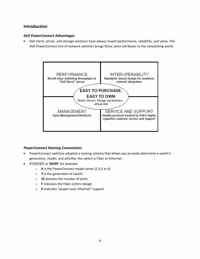
Dell PowerConnect Advantages • Dell client, server, and storage solutions have always meant performance, reliability, and value. The
Dell PowerConnect line of network switches brings those same attributes to the networking world.
PowerConnect Naming Conventions • PowerConnect switches adopted a naming schema that allows you to easily determine a switch’s
generation, model, and whether the switch is Fiber or Ethernet.
• XYZZ(F)(P) or 3424P, for example o X is the PowerConnect model series (2,3,5 or 6) o Y is the generation of switch o ZZ denotes the number of ports o F indicates the Fiber‐centric design o P indicates “power‐over‐Ethernet” support
5
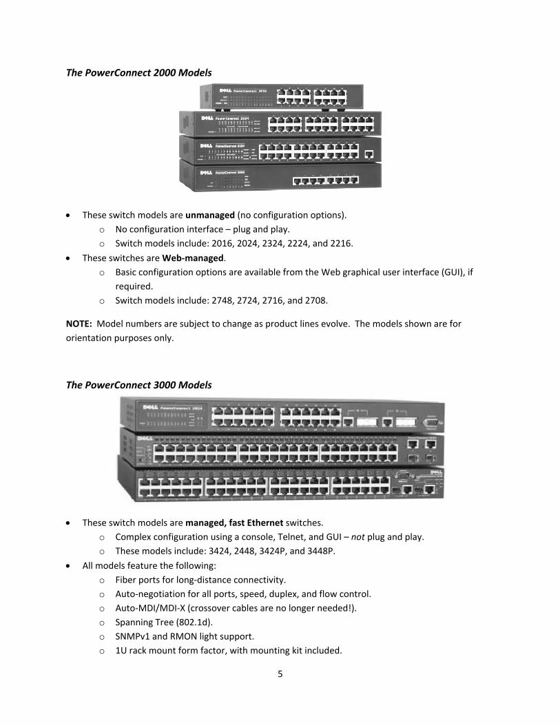
The PowerConnect 2000 Models
• These switch models are unmanaged (no configuration options). o No configuration interface – plug and play. o Switch models include: 2016, 2024, 2324, 2224, and 2216.
• These switches are Web‐managed. o Basic configuration options are available from the Web graphical user interface (GUI), if
required. o Switch models include: 2748, 2724, 2716, and 2708.
NOTE: Model numbers are subject to change as product lines evolve. The models shown are for orientation purposes only.
The PowerConnect 3000 Models
• These switch models are managed, fast Ethernet switches. o Complex configuration using a console, Telnet, and GUI – not plug and play. o These models include: 3424, 2448, 3424P, and 3448P.
• All models feature the following: o Fiber ports for long‐distance connectivity. o Auto‐negotiation for all ports, speed, duplex, and flow control. o Auto‐MDI/MDI‐X (crossover cables are no longer needed!). o Spanning Tree (802.1d). o SNMPv1 and RMON light support. o 1U rack mount form factor, with mounting kit included.
6
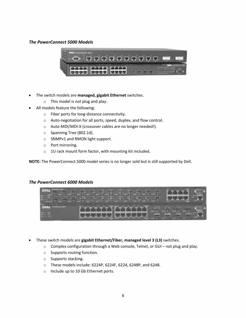
The PowerConnect 5000 Models
• The switch models are managed, gigabit Ethernet switches. o This model is not plug and play.
• All models feature the following: o Fiber ports for long‐distance connectivity. o Auto‐negotiation for all ports, speed, duplex, and flow control. o Auto‐MDI/MDI‐X (crossover cables are no longer needed!). o Spanning Tree (802.1d). o SNMPv1 and RMON light support. o Port mirroring. o 1U rack mount form factor, with mounting kit included.
NOTE: The PowerConnect 5000 model series is no longer sold but is still supported by Dell.
The PowerConnect 6000 Models
• These switch models are gigabit Ethernet/Fiber, managed level 3 (L3) switches. o Complex configuration through a Web console, Telnet, or GUI – not plug and play. o Supports routing function. o Supports stacking. o These models include: 6224P, 6224F, 6224, 6248P, and 6248. o Include up to 10 Gb Ethernet ports.
7
Troubleshooting
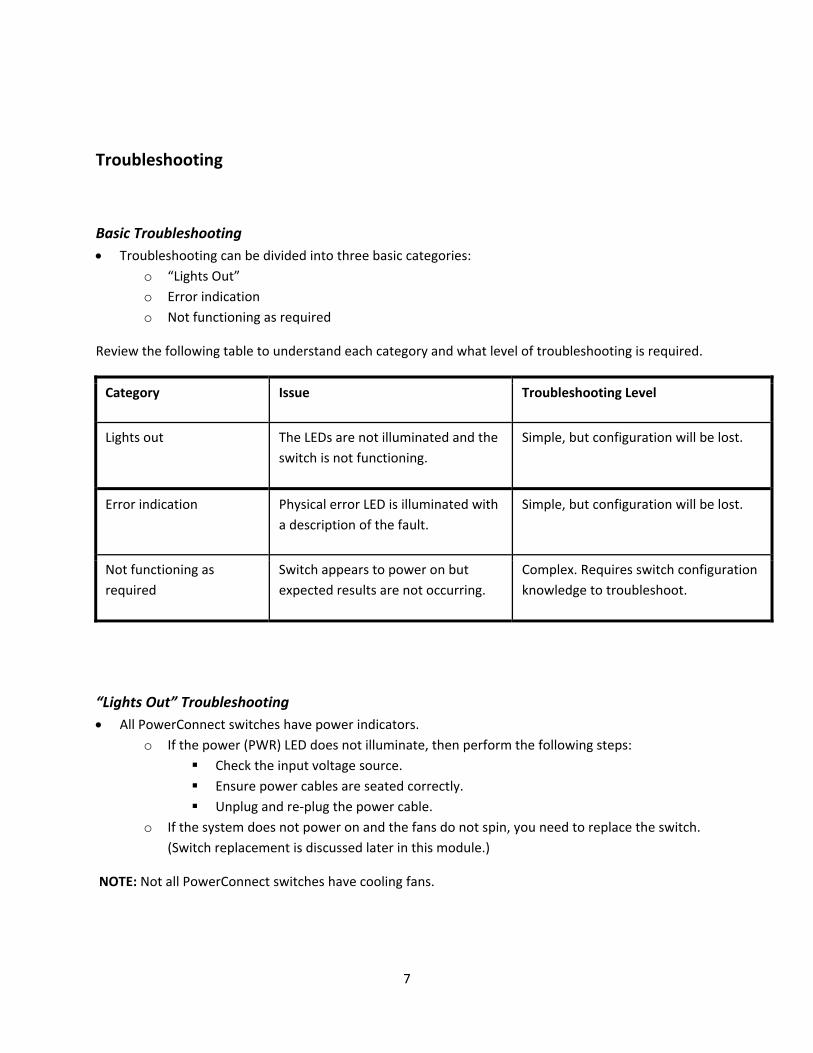
Basic Troubleshooting • Troubleshooting can be divided into three basic categories:
o “Lights Out” o Error indication o Not functioning as required
Review the following table to understand each category and what level of troubleshooting is required.
Category Issue Troubleshooting Level
Lights out The LEDs are not illuminated and the switch is not functioning.
Simple, but configuration will be lost.
Error indication Physical error LED is illuminated with a description of the fault.
Simple, but configuration will be lost.
Not functioning as required
Switch appears to power on but expected results are not occurring.
Complex. Requires switch configuration knowledge to troubleshoot.
“Lights Out” Troubleshooting • All PowerConnect switches have power indicators.
o If the power (PWR) LED does not illuminate, then perform the following steps: Check the input voltage source. Ensure power cables are seated correctly. Unplug and re‐plug the power cable.
o If the system does not power on and the fans do not spin, you need to replace the switch. (Switch replacement is discussed later in this module.)
NOTE: Not all PowerConnect switches have cooling fans.
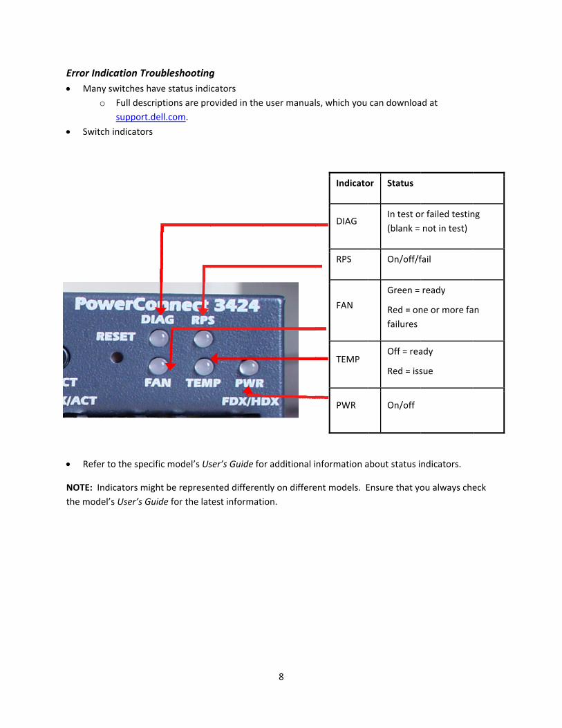
Error Ind• Many
o
• Switc
• Refer
NOTE: Inthe mode
dication Trouy switches hav Full descri
support.de
h indicators
to the specif
dicators mighel’s User’s Gui
ubleshootingve status indiptions are proell.com.
fic model’s Us
ht be represeide for the lat
g cators ovided in the
ser’s Guide fo
nted differentest informati
8
e user manual
or additional i
ntly on differeion.
ls, which you
Indicato
DIAG
RPS
FAN
TEMP
PWR
nformation a
ent models. E
can downloa
or Status
In test o(blank =
On/off/f
Green =
Red = onfailures
Off = rea
Red = iss
On/off
about status i
Ensure that yo
ad at
r failed testinnot in test)
fail
ready
ne or more fa
ady
sue
ndicators.
ou always che
ng
an
eck
9
Not Functioning as Required Troubleshooting • This troubleshooting type is the most difficult to perform on PowerConnect switches.
• If a switch powers up and there are no error indications, the issue might not be related to the switch, especially with high‐complexity switches. o For non‐manageable switches:
Verify all connections. Monitor behaviour. If behaviour continues, replace the switch.
o For manageable switches: Verify the configuration if at all possible.
Not Functioning as Required – Verifying the Configuration • Switch failure can only happen if the switch was functional at some point.
o Verify that the switch ever worked. o Did anything get changed in the configuration? o Has anyone interfered in the switch closet?
• Attempt to restore a backup of the configuration. o ALWAYS save the configuration to a hard drive (either desktop or laptop). o Attempt to reset and restore the configuration.
• If the switch never worked, it might not have been configured correctly. o Stop and seek expert switch configuration assistance. You can also go to support.dell.com for
assistance.
10
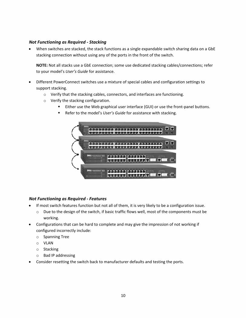
Not Functioning as Required ‐ Stacking • When switches are stacked, the stack functions as a single expandable switch sharing data on a GbE
stacking connection without using any of the ports in the front of the switch.
NOTE: Not all stacks use a GbE connection; some use dedicated stacking cables/connections; refer to your model’s User’s Guide for assistance.
• Different PowerConnect switches use a mixture of special cables and configuration settings to support stacking.
o Verify that the stacking cables, connectors, and interfaces are functioning. o Verify the stacking configuration.
Either use the Web graphical user interface (GUI) or use the front‐panel buttons. Refer to the model’s User’s Guide for assistance with stacking.
Not Functioning as Required ‐ Features • If most switch features function but not all of them, it is very likely to be a configuration issue.
o Due to the design of the switch, if basic traffic flows well, most of the components must be working.
• Configurations that can be hard to complete and may give the impression of not working if configured incorrectly include: o Spanning Tree o VLAN o Stacking o Bad IP addressing
• Consider resetting the switch back to manufacturer defaults and testing the ports.
11
Configuration Tips • Command‐line commands are similar, but not always the same as switches from other
manufacturers.
• Configuration changes must be saved before rebooting or they will be lost.
• To eliminate a configuration, delete the configuration file.
• Learn the Command‐Line Interface (CLI) commands.
• Back‐up the configuration file after you get a switch working.
NOTE: The PowerConnect 2000 models (unmanaged) do not have configuration options.
Replacing a Switch
Replacing a Switch – Non‐functioning Switch • If the current switch will not power up, unplug all data cables, but note where they came from.
o Perform the following steps:
1. Remove the power at the socket/source.
2. Remove the power cable from the switch.
3. Install the new switch.
4. If this is a managed switch, restore the configuration file or reconfigure.
NOTE: If the old switch is broken, you cannot remove the configuration file from it.
Replacing a Switch – Functioning Switch • If the current switch is functioning, you must plan for down‐time to replace the switch.
o Perform the following steps:
1. Copy the configuration file for managed switches to a hard drive (either on a desktop or laptop).
2. Unplug all data cables, but note where they came from.
3. Remove the power at the socket/source.
4. Remove the power cable from the switch.
5. Install the new switch.
6. If you are replacing a managed switch, restore the configuration file or reconfigure the switch.
Setting
Initial Se• Befor
Setupo
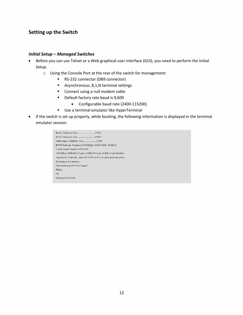
• If the emula
up the Sw
etup – Manae you can usep. Using the C
RS As Co De
Us
switch is set ator session:
witch
aged Switchee Telnet or a W
Console Port S‐232 connectsynchronous, onnect using aefault factory
• Configuse a terminal
up properly,
es Web graphica
at the rear otor (DB9 conn8,1,N termina null modem rate baud is
urable baud remulator like
while bootin
12
al user interfa
f the switch fnector) al settings
m cable 9,600
rate (2400‐11e HyperTermi
g, the followi
ace (GUI), you
for managem
5200) inal
ing informatio
u need to per
ent:
on is displaye
rform the Init
ed in the term
tial
minal
Initial Se
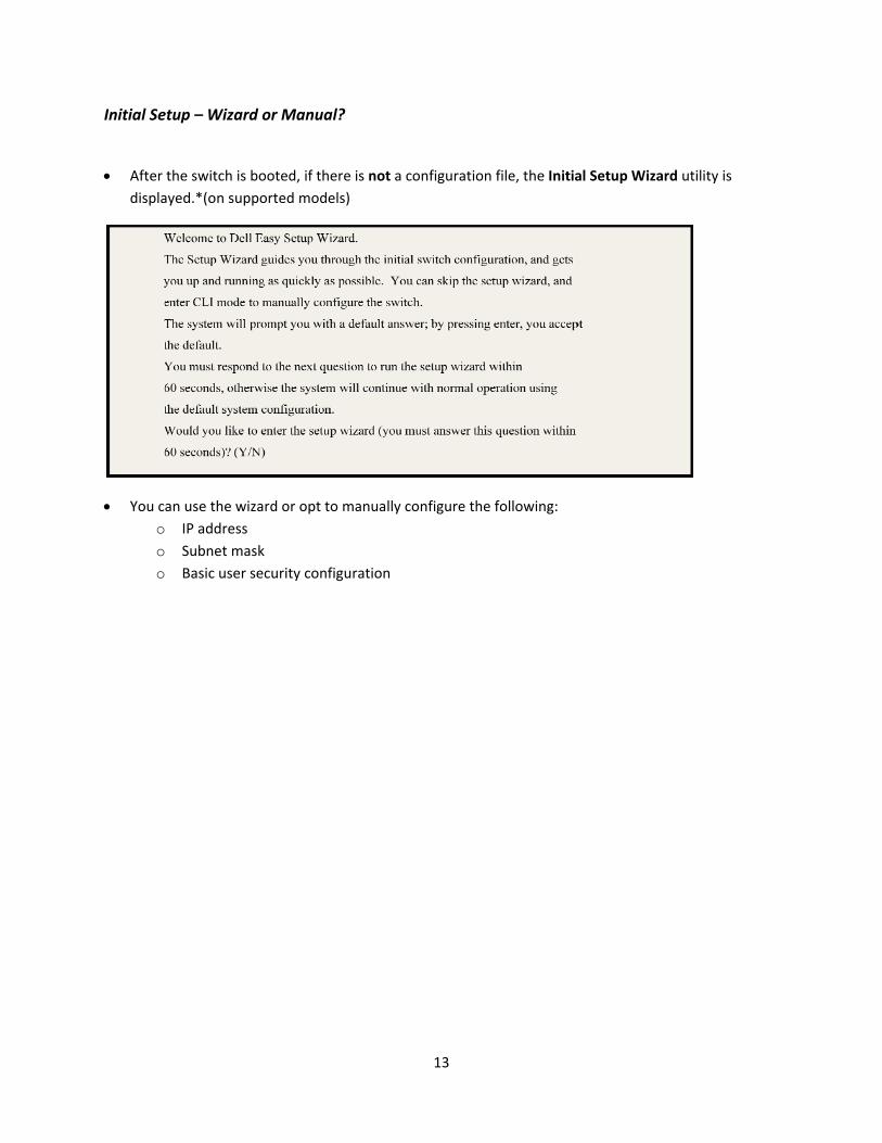
• After displa
• You cooo
etup – Wizar
the switch is ayed.*(on sup
an use the w IP address Subnet ma Basic user
rd or Manua
booted, if thpported mode
izard or opt t ask security conf
al?
ere is not a cels)
o manually co
figuration
13
onfiguration
onfigure the f
file, the Initia
following:
al Setup Wizaard utility is

14
Configuring and Backing Up the Switch
Initial Configuration – Manual Method • Commands might vary by switch:
o IP address commands:
Console> enable
Console# conf
Console (config) # int vlan 1
Console (config‐if) # ip address 192.168.245.210 /24
Console (config‐if) # exit
Console (config) # ip default‐gateway 192.168.245.1
o User ID commands:
Console (config) # username admin password admin level 15
o Save the configuration file (the file is discarded at reboot otherwise)
Console# copy run start
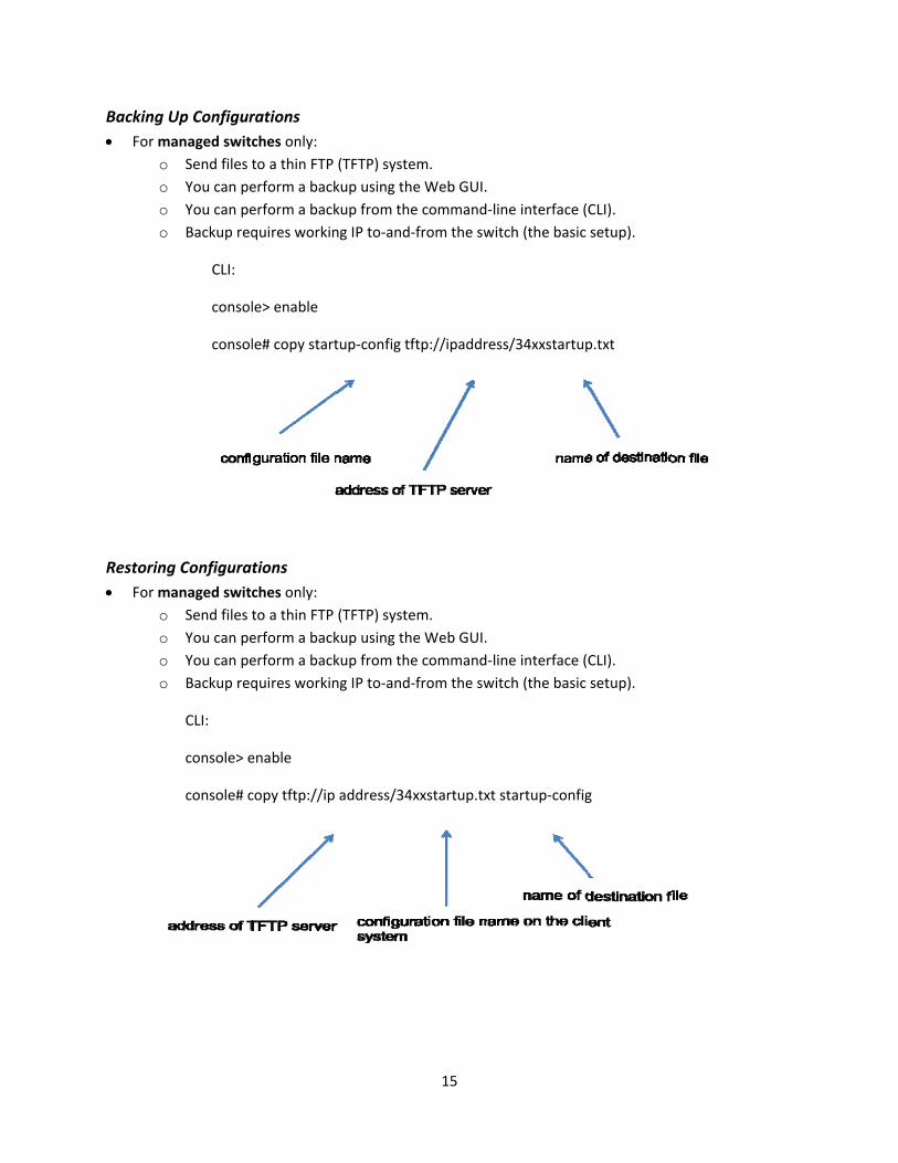
Backing • For m
oooo
Restoring• For m
oooo
Up Configurmanaged switc
Send files t You can pe You can pe Backup req
CLI:
consol
consol
g Configuramanaged switc
Send files t You can pe You can pe Backup req
CLI:
console> e
console# c
rations ches only: to a thin FTP erform a backerform a backquires workin
le> enable
le# copy start
tions ches only: to a thin FTP erform a backerform a backquires workin
enable
copy tftp://ip
(TFTP) systemkup using thekup from the ng IP to‐and‐f
tup‐config tft
(TFTP) systemkup using thekup from the ng IP to‐and‐f
address/34xx
15
m. Web GUI. command‐linfrom the swit
p://ipaddress
m. Web GUI. command‐linfrom the swit
xstartup.txt s
ne interface (ch (the basic
s/34xxstartup
ne interface (ch (the basic
startup‐config
CLI). setup).
p.txt
CLI). setup).
g
16
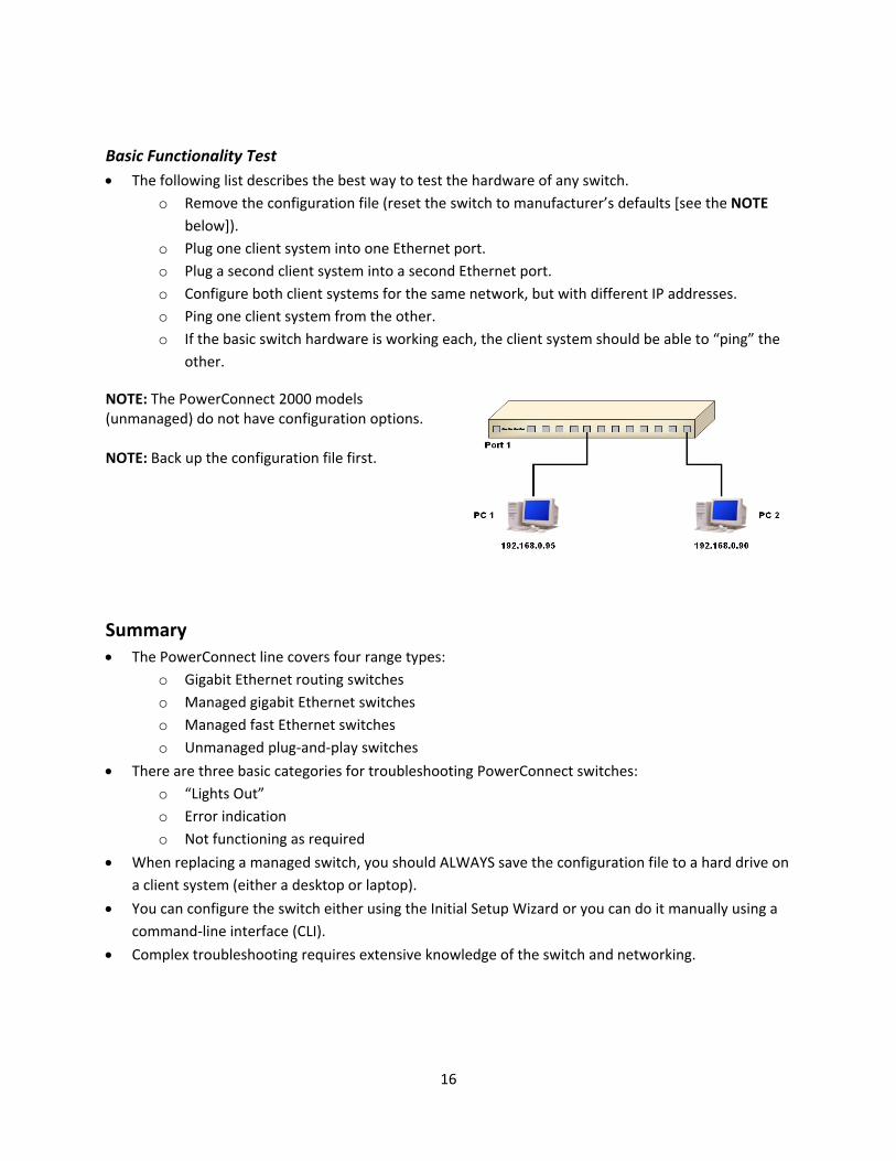
Basic Functionality Test • The following list describes the best way to test the hardware of any switch.
o Remove the configuration file (reset the switch to manufacturer’s defaults [see the NOTE below]).
o Plug one client system into one Ethernet port. o Plug a second client system into a second Ethernet port. o Configure both client systems for the same network, but with different IP addresses. o Ping one client system from the other. o If the basic switch hardware is working each, the client system should be able to “ping” the
other.
NOTE: The PowerConnect 2000 models (unmanaged) do not have configuration options. NOTE: Back up the configuration file first.
Summary • The PowerConnect line covers four range types:
o Gigabit Ethernet routing switches o Managed gigabit Ethernet switches o Managed fast Ethernet switches o Unmanaged plug‐and‐play switches
• There are three basic categories for troubleshooting PowerConnect switches: o “Lights Out” o Error indication o Not functioning as required
• When replacing a managed switch, you should ALWAYS save the configuration file to a hard drive on a client system (either a desktop or laptop).
• You can configure the switch either using the Initial Setup Wizard or you can do it manually using a command‐line interface (CLI).
• Complex troubleshooting requires extensive knowledge of the switch and networking.