Embed Size (px)
Citation preview
A Dell Reference Architecture
Dell Wyse Datacenter for VMware Horizon View Reference Architecture
A Reference Architecture for the design, configuration and implementation of a VMware Horizon View environment.
Dell Wyse Solutions Engineering July 2015
2 Dell Wyse Datacenter for VMware Horizon View Reference Architecture | v.6.7
Revisions
Date Description
May 2014 Initial release (v.6.5)
November 2014 Updated to include 13g servers and increased VM density (v.6.6)
November 2014 Updated cloud client graphics and nomenclature (v.6.6.1)
July 2015 Updated density numbers for ESXi 6.0 and added PowerEdge C4130 (v.6.7)
3 Dell Wyse Datacenter for VMware Horizon View Reference Architecture | v.6.7
THIS WHITE PAPER IS FOR INFORMATIONAL PURPOSES ONLY, AND MAY CONTAIN TYPOGRAPHICAL ERRORS AND
TECHNICAL INACCURACIES. THE CONTENT IS PROVIDED AS IS, WITHOUT EXPRESS OR IMPLIED WARRANTIES OF
ANY KIND.
© 2015 Dell Inc. All rights reserved. Reproduction of this material in any manner whatsoever without the express
written permission of Dell Inc. is strictly forbidden. For more information, contact Dell.
PRODUCT WARRANTIES APPLICABLE TO THE DELL PRODUCTS DESCRIBED IN THIS DOCUMENT MAY BE FOUND
AT: http://www.dell.com/learn/us/en/19/terms-of-sale-commercial-and-public-sector Performance of network
reference architectures discussed in this document may vary with differing deployment conditions, network loads, and
the like. Third party products may be included in reference architectures for the convenience of the reader. Inclusion
of such third party products does not necessarily constitute Dell’s recommendation of those products. Please consult
your Dell representative for additional information.
Trademarks used in this text:
Dell™, the Dell logo, Dell Boomi™, Dell Precision™ ,OptiPlex™, Latitude™, PowerEdge™, PowerVault™,
PowerConnect™, OpenManage™, EqualLogic™, Compellent™, KACE™, FlexAddress™, Force10™ and Vostro™ are
trademarks of Dell Inc. Other Dell trademarks may be used in this document. Cisco Nexus®, Cisco MDS®, Cisco NX-
0S®, and other Cisco Catalyst® are registered trademarks of Cisco System Inc. EMC VNX®, and EMC Unisphere® are
registered trademarks of EMC Corporation. Intel®, Pentium®, Xeon®, Core® and Celeron® are registered trademarks of
Intel Corporation in the U.S. and other countries. AMD® is a registered trademark and AMD Opteron™, AMD
Phenom™ and AMD Sempron™ are trademarks of Advanced Micro Devices, Inc. Microsoft®, Windows®, Windows
Server®, Internet Explorer®, MS-DOS®, Windows Vista® and Active Directory® are either trademarks or registered
trademarks of Microsoft Corporation in the United States and/or other countries. Red Hat® and Red Hat® Enterprise
Linux® are registered trademarks of Red Hat, Inc. in the United States and/or other countries. Novell® and SUSE® are
registered trademarks of Novell Inc. in the United States and other countries. Oracle® is a registered trademark of
Oracle Corporation and/or its affiliates. Citrix®, Xen®, XenServer® and XenMotion® are either registered trademarks or
trademarks of Citrix Systems, Inc. in the United States and/or other countries. VMware®, Virtual SMP®, vMotion®,
vCenter® and vSphere® are registered trademarks or trademarks of VMware, Inc. in the United States or other
countries. IBM® is a registered trademark of International Business Machines Corporation. Broadcom® and
NetXtreme® are registered trademarks of Broadcom Corporation. QLogic is a registered trademark of QLogic
Corporation. Other trademarks and trade names may be used in this document to refer to either the entities claiming
the marks and/or names or their products and are the property of their respective owners. Dell disclaims proprietary
interest in the marks and names of others.
4 Dell Wyse Datacenter for VMware Horizon View Reference Architecture | v.6.7
Table of contents Revisions ............................................................................................................................................................................................. 2
1 Introduction ................................................................................................................................................................................ 9
1.1 Purpose of this document ............................................................................................................................................. 9
1.2 Scope ................................................................................................................................................................................ 9
1.3 New in this release .......................................................................................................................................................... 9
2 Solution architecture overview ............................................................................................................................................. 10
2.1 Introduction ................................................................................................................................................................... 10
2.1.1 Physical architecture overview .................................................................................................................................... 11
2.1.2 Dell Wyse Datacenter – solution layers .................................................................................................................... 12
2.2 Local Tier 1 ..................................................................................................................................................................... 13
2.2.1 Local Tier 1 – 50 user combined pilot ...................................................................................................................... 13
2.2.2 Local Tier 1 – 50 user scale-ready pilot.................................................................................................................... 13
2.2.3 Local Tier 1 (iSCSI) ......................................................................................................................................................... 14
2.3 Shared Tier 1 – Rack ..................................................................................................................................................... 17
2.3.1 Shared Tier 1 – Rack – 555 users (iSCSI) .................................................................................................................. 17
2.3.2 Shared Tier 1 – Rack (iSCSI – EQL) ............................................................................................................................ 18
2.3.3 Shared Tier 1 – Rack – 1000 users (FC – CML) ...................................................................................................... 21
2.4 Shared Tier 1 – Blade ................................................................................................................................................... 24
2.4.1 Shared Tier 1 – Blade – 555 users (iSCSI – EQL) .................................................................................................... 24
2.4.2 Shared Tier 1 – Blade (iSCSI – EQL) .......................................................................................................................... 25
2.4.3 Shared Tier 1 – Blade (FC – CML) .............................................................................................................................. 28
3 Hardware components ........................................................................................................................................................... 31
3.1 Networking ..................................................................................................................................................................... 31
3.1.1 Force10 S55 (ToR switch) ............................................................................................................................................ 31
3.1.2 Force10 S60 (1Gb ToR switch) ................................................................................................................................... 32
3.1.3 Force10 S4810 (10Gb ToR switch) ............................................................................................................................. 33
3.1.4 Brocade 6510 (FC ToR switch) ................................................................................................................................... 35
3.1.5 PowerEdge M I/O Aggregator (10Gb blade interconnect) .................................................................................... 36
3.1.6 PowerConnect M6348 (1Gb blade interconnect) ................................................................................................... 36
3.1.7 Brocade M5424 (FC blade interconnect) ................................................................................................................. 37
3.2 Servers ............................................................................................................................................................................. 38
5 Dell Wyse Datacenter for VMware Horizon View Reference Architecture | v.6.7
3.2.1 PowerEdge R730 ........................................................................................................................................................... 38
3.2.2 PowerEdge M620.......................................................................................................................................................... 38
3.3 Storage ............................................................................................................................................................................ 39
3.3.1 EqualLogic Tier 1 storage (iSCSI) ................................................................................................................................ 39
3.3.2 EqualLogic Tier 2 storage (iSCSI)............................................................................................................................... 40
3.3.3 Compellent storage (FC).............................................................................................................................................. 47
3.3.4 NAS .................................................................................................................................................................................. 50
3.4 Wyse Cloud Clients ....................................................................................................................................................... 51
3.4.1 Wyse 5020-P25 ............................................................................................................................................................. 51
3.4.2 Wyse 5012-D10DP ........................................................................................................................................................ 51
3.4.3 Wyse 7020-P45 ............................................................................................................................................................. 51
3.4.4 Wyse 7250-Z50D .......................................................................................................................................................... 52
3.4.5 Wyse 7290-Z90D7 ........................................................................................................................................................ 52
3.4.6 Wyse 7490-Z90Q8 ....................................................................................................................................................... 52
3.4.7 Dell Chromebook 11 ..................................................................................................................................................... 52
4 Software components ............................................................................................................................................................ 54
4.1 What's new in this release of Horizon View 6.0? .................................................................................................... 54
4.2 VMware Horizon View .................................................................................................................................................. 55
4.3 VDI hypervisor platform ............................................................................................................................................... 56
4.3.1 VMware vSphere 5 ........................................................................................................................................................ 56
5 Solution architecture ............................................................................................................................................................... 57
5.1 Compute server infrastructure ................................................................................................................................... 57
5.1.1 Local Tier 1 – Rack........................................................................................................................................................ 57
5.1.2 Shared Tier 1 – Rack ..................................................................................................................................................... 57
5.1.3 Shared Tier 1 – Blade ................................................................................................................................................... 58
5.2 Management server infrastructure ............................................................................................................................. 59
5.2.1 SQL databases .............................................................................................................................................................. 60
5.2.2 DNS ................................................................................................................................................................................. 60
5.3 Scaling guidance ........................................................................................................................................................... 61
5.3.1 Windows 7 – vSphere .................................................................................................................................................. 62
5.3.2 Windows 8 – vSphere .................................................................................................................................................. 63
5.3.3 Windows 8.1 – vSphere ............................................................................................................................................... 64
6 Dell Wyse Datacenter for VMware Horizon View Reference Architecture | v.6.7
5.3.4 Windows 2008R2 – vSphere ...................................................................................................................................... 64
5.4 Storage architecture overview .................................................................................................................................... 65
5.4.1 Local Tier 1 storage ....................................................................................................................................................... 65
5.4.2 Shared Tier 1 storage .................................................................................................................................................... 65
5.4.3 Shared Tier 2 storage ................................................................................................................................................... 66
5.4.4 Storage networking – EqualLogic iSCSI ................................................................................................................... 66
5.4.5 Storage networking – Compellent Fibre Channel .................................................................................................. 68
5.5 Virtual networking ......................................................................................................................................................... 69
5.5.1 Local Tier 1 – Rack – iSCSI ......................................................................................................................................... 69
5.5.2 Shared Tier 1 – Rack – iSCSI ....................................................................................................................................... 71
5.5.3 Shared Tier 1 – Rack – Fibre Channel ....................................................................................................................... 74
5.5.4 Shared Tier 1 – Blade – iSCSI ..................................................................................................................................... 75
5.5.5 Shared Tier 1 – Blade – Fibre Channel ..................................................................................................................... 77
5.6 Solution high availability .............................................................................................................................................. 79
5.6.1 Compute layer HA (Local Tier 1) ............................................................................................................................... 80
5.6.2 vSphere HA (Shared Tier 1) .......................................................................................................................................... 81
5.6.3 Horizon View infrastructure protection .................................................................................................................... 81
5.6.4 Management server high availability ......................................................................................................................... 82
5.6.5 Horizon View VCS high availability ............................................................................................................................ 82
5.6.6 Windows File Services high availability ...................................................................................................................... 82
5.6.7 SQL Server high availability ......................................................................................................................................... 83
5.6.8 Load balancing .............................................................................................................................................................. 83
5.7 VMware Horizon View communication flow ........................................................................................................... 84
6 Customer-provided solution components ......................................................................................................................... 85
6.1 Customer-provided storage requirements .............................................................................................................. 85
6.2 Customer-provided switching requirements .......................................................................................................... 85
7 Solution performance and testing ........................................................................................................................................ 86
7.1 Load generation and monitoring ............................................................................................................................... 86
7.1.1 VMware View Planner................................................................................................................................................... 86
7.1.2 Login VSI – Login Consultants ................................................................................................................................... 86
7.1.3 Liquidware Labs Stratusphere UX ............................................................................................................................... 86
7.1.4 EqualLogic SAN HQ ...................................................................................................................................................... 87
7 Dell Wyse Datacenter for VMware Horizon View Reference Architecture | v.6.7
7.1.5 VMware vCenter ............................................................................................................................................................ 87
7.2 Performance analysis methodology .......................................................................................................................... 88
7.2.1 Resource utilization ...................................................................................................................................................... 88
7.2.2 EUE tools information .................................................................................................................................................. 89
7.2.3 EUE real user information ............................................................................................................................................ 89
7.2.4 Dell Wyse Datacenter workloads and profiles ......................................................................................................... 89
7.2.5 Dell Wyse Datacenter profiles ................................................................................................................................... 90
7.2.6 Dell Wyse Datacenter workloads .............................................................................................................................. 90
7.2.7 Workloads running on shared graphics profile ....................................................................................................... 92
7.2.8 Workloads running on dedicated graphics profile .................................................................................................. 92
7.3 Testing and validation .................................................................................................................................................. 92
7.3.1 Testing process ............................................................................................................................................................. 92
7.4 VMware Horizon View test results ............................................................................................................................. 93
7.4.1 Configuration ................................................................................................................................................................. 93
7.4.2 ESXi 6.0/View 6.1 ........................................................................................................................................................... 95
7.5 Dell PowerEdge C4130 testing ................................................................................................................................. 103
7.5.1 Configuration ............................................................................................................................................................... 103
7.5.2 Test results ................................................................................................................................................................... 104
7.6 Dell EqualLogic PS6210XS testing with VMware Horizon View ......................................................................... 110
7.6.1 Overview ....................................................................................................................................................................... 110
7.6.2 Compute resources ..................................................................................................................................................... 111
7.6.3 Network resources ...................................................................................................................................................... 111
7.6.4 iSCSI SAN configuration overview ........................................................................................................................... 112
7.6.5 Test objectives: ............................................................................................................................................................ 112
7.6.6 Test criteria/thresholds: ............................................................................................................................................. 113
7.6.7 Boot storm I/O ............................................................................................................................................................ 113
7.6.8 Login storm I/O ........................................................................................................................................................... 114
7.6.9 Steady state I/O ........................................................................................................................................................... 116
7.6.10 Server host performance ...................................................................................................................................... 118
7.6.11 Summary ....................................................................................................................................................................... 119
Acknowledgements ...................................................................................................................................................................... 121
About the authors ......................................................................................................................................................................... 121

8 Dell Wyse Datacenter for VMware Horizon View Reference Architecture | v.6.7
9 Dell Wyse Datacenter for VMware Horizon View Reference Architecture | v.6.7
1 Introduction
1.1 Purpose of this document This document describes:
Dell Wyse Datacenter for VMware Horizon View Reference Architecture scaling from 50 to
50,000+ virtual desktop infrastructure (VDI) users.
Solution options encompass a combination of solution models including local disks, iSCSI or Fibre
Channel based storage options.
This document addresses the architecture design, configuration and implementation considerations for
the key components of the architecture required to deliver virtual desktops via VMware Horizon View on
VMware vSphere 5.
1.2 Scope Relative to delivering the virtual desktop environment, the objectives of this document are to:
Define the detailed technical design for the solution.
Define the hardware requirements to support the design.
Define the design constraints which are relevant to the design.
Define relevant risks, issues, assumptions and concessions – referencing existing ones where
possible.
Provide a breakdown of the design into key elements such that the reader receives an incremental
or modular explanation of the design.
Provide solution scaling and component selection guidance.
1.3 New in this release RDS based desktop and Remote App support - http://dell.to/QRqAud
View 6 Cloud POD Architecture - http://dell.to/1gOGrB5
See the attached hyperlinks for focused white papers on each of the above topics.
10 Dell Wyse Datacenter for VMware Horizon View Reference Architecture | v.6.7
2 Solution architecture overview
2.1 Introduction The Dell Wyse Datacenter Solution leverages a core set of hardware and software components consisting
of 4 primary layers:
Networking Layer
Compute Server Layer
Management Server Layer
Storage Layer
These components have been integrated and tested to provide the optimal balance of high performance
and lowest cost per user. Additionally, the Dell Wyse Datacenter Solution includes an approved extended
list of optional components in the same categories. These components give IT departments the flexibility
to custom tailor the solution for environments with unique virtual desktop infrastructure (VDI) feature,
scale or performance needs. The Dell Wyse Datacenter stack is designed to be a cost effective starting
point for IT departments looking to migrate to a fully virtualized desktop environment slowly. This
approach allows you to grow the investment and commitment as needed or as your IT staff becomes
more comfortable with VDI technologies.
11 Dell Wyse Datacenter for VMware Horizon View Reference Architecture | v.6.7
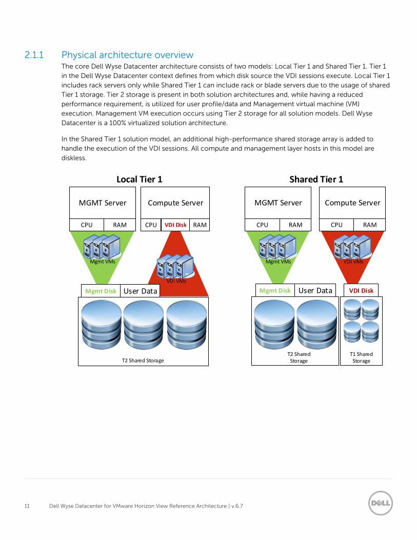
2.1.1 Physical architecture overview The core Dell Wyse Datacenter architecture consists of two models: Local Tier 1 and Shared Tier 1. Tier 1
in the Dell Wyse Datacenter context defines from which disk source the VDI sessions execute. Local Tier 1
includes rack servers only while Shared Tier 1 can include rack or blade servers due to the usage of shared
Tier 1 storage. Tier 2 storage is present in both solution architectures and, while having a reduced
performance requirement, is utilized for user profile/data and Management virtual machine (VM)
execution. Management VM execution occurs using Tier 2 storage for all solution models. Dell Wyse
Datacenter is a 100% virtualized solution architecture.
In the Shared Tier 1 solution model, an additional high-performance shared storage array is added to
handle the execution of the VDI sessions. All compute and management layer hosts in this model are
diskless.
User DataMgmt Disk
MGMT Server
CPU RAM
T2 Shared Storage
Mgmt VMs
VDI VMs
Compute Server
CPU RAMVDI Disk
Local Tier 1
VDI DiskUser Data
MGMT Server
CPU RAM
T1 Shared Storage
Mgmt VMs VDI VMs
Compute Server
CPU RAM
T2 Shared Storage
Mgmt Disk
Shared Tier 1
12 Dell Wyse Datacenter for VMware Horizon View Reference Architecture | v.6.7
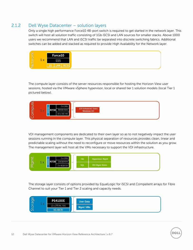
2.1.2 Dell Wyse Datacenter – solution layers Only a single high performance Force10 48-port switch is required to get started in the network layer. This
switch will host all solution traffic consisting of 1Gb iSCSI and LAN sources for smaller stacks. Above 1000
users we recommend that LAN and iSCSI traffic be separated into discrete switching fabrics. Additional
switches can be added and stacked as required to provide High Availability for the Network layer.
The compute layer consists of the server resources responsible for hosting the Horizon View user
sessions, hosted via the VMware vSphere hypervisor, local or shared tier 1 solution models (local Tier 1
pictured below).
VDI management components are dedicated to their own layer so as to not negatively impact the user
sessions running in the compute layer. This physical separation of resources provides clean, linear and
predictable scaling without the need to reconfigure or move resources within the solution as you grow.
The management layer will host all the VMs necessary to support the VDI infrastructure.
The storage layer consists of options provided by EqualLogic for iSCSI and Compellent arrays for Fibre
Channel to suit your Tier 1 and Tier 2 scaling and capacity needs.
13 Dell Wyse Datacenter for VMware Horizon View Reference Architecture | v.6.7
2.2 Local Tier 1
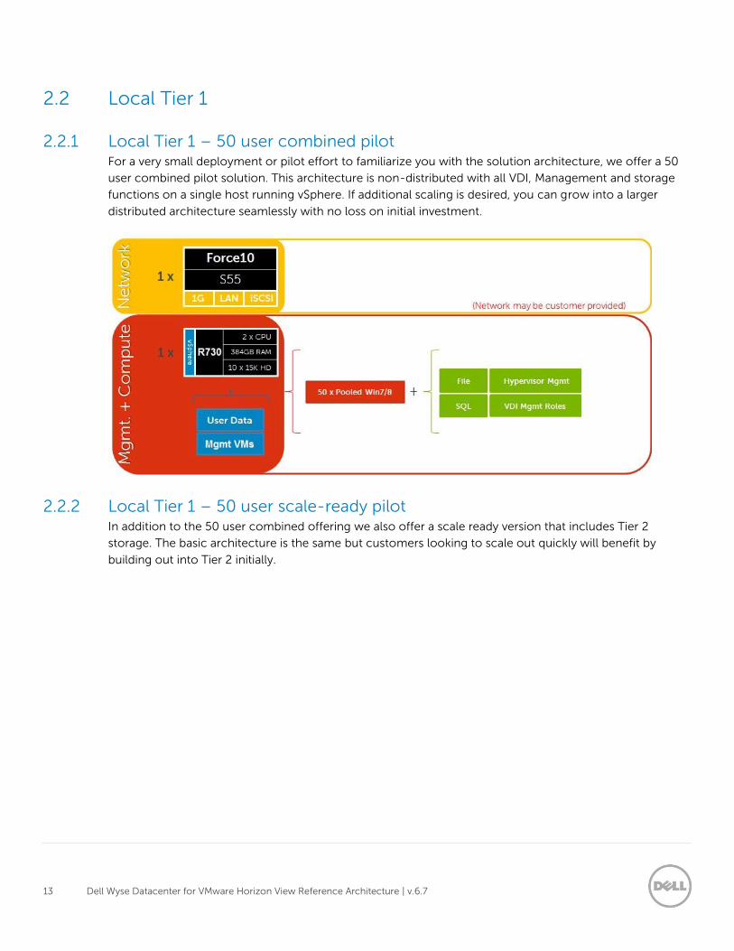
2.2.1 Local Tier 1 – 50 user combined pilot For a very small deployment or pilot effort to familiarize you with the solution architecture, we offer a 50
user combined pilot solution. This architecture is non-distributed with all VDI, Management and storage
functions on a single host running vSphere. If additional scaling is desired, you can grow into a larger
distributed architecture seamlessly with no loss on initial investment.
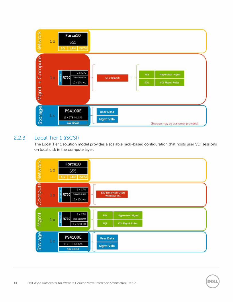
2.2.2 Local Tier 1 – 50 user scale-ready pilot In addition to the 50 user combined offering we also offer a scale ready version that includes Tier 2
storage. The basic architecture is the same but customers looking to scale out quickly will benefit by
building out into Tier 2 initially.
14 Dell Wyse Datacenter for VMware Horizon View Reference Architecture | v.6.7
2.2.3 Local Tier 1 (iSCSI) The Local Tier 1 solution model provides a scalable rack-based configuration that hosts user VDI sessions
on local disk in the compute layer.
15 Dell Wyse Datacenter for VMware Horizon View Reference Architecture | v.6.7
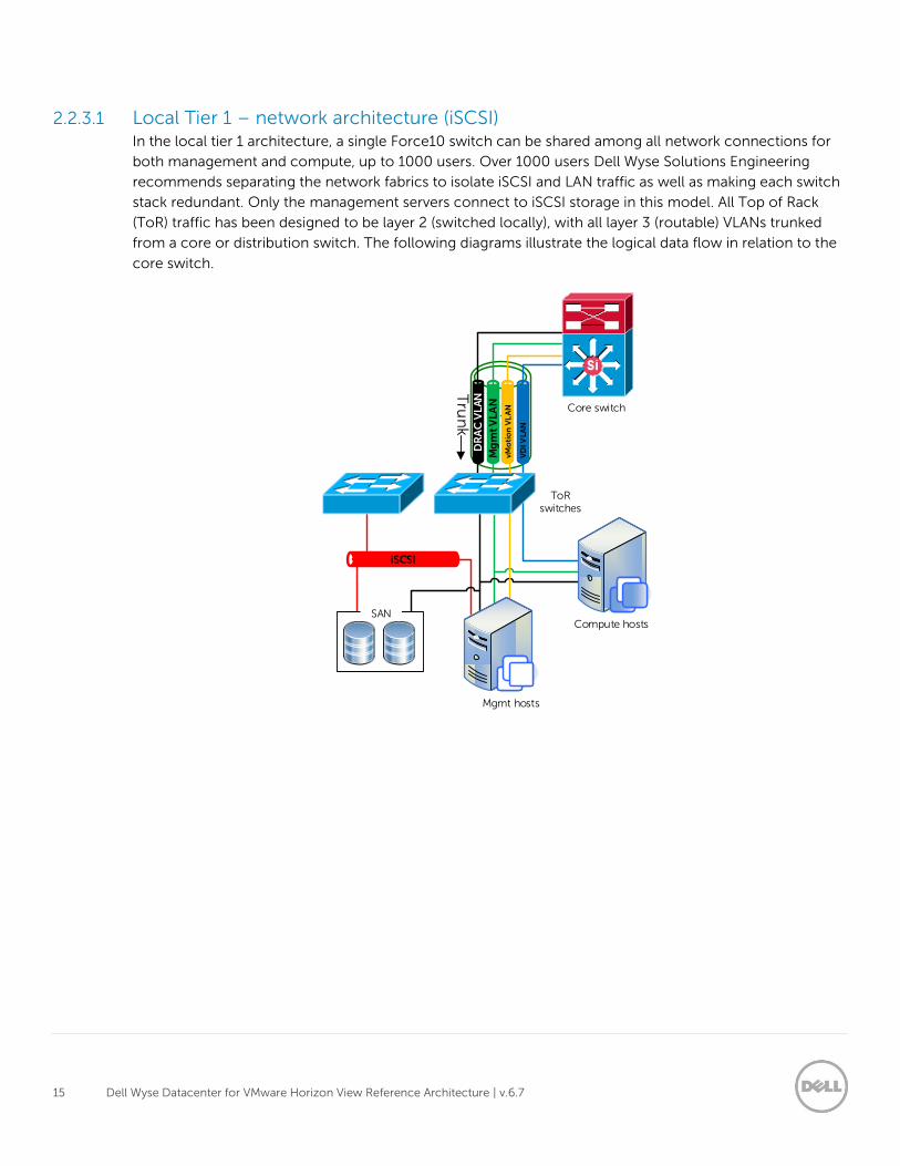
2.2.3.1 Local Tier 1 – network architecture (iSCSI) In the local tier 1 architecture, a single Force10 switch can be shared among all network connections for
both management and compute, up to 1000 users. Over 1000 users Dell Wyse Solutions Engineering
recommends separating the network fabrics to isolate iSCSI and LAN traffic as well as making each switch
stack redundant. Only the management servers connect to iSCSI storage in this model. All Top of Rack
(ToR) traffic has been designed to be layer 2 (switched locally), with all layer 3 (routable) VLANs trunked
from a core or distribution switch. The following diagrams illustrate the logical data flow in relation to the
core switch.
DR
AC
VL
AN
Mg
mt
VL
AN
iSCSI
Mgmt hosts
Compute hosts
Core switch
Tru
nk
SAN
VD
I VLA
N
ToR switches
vMo
tio
n V
LA
N
16 Dell Wyse Datacenter for VMware Horizon View Reference Architecture | v.6.7
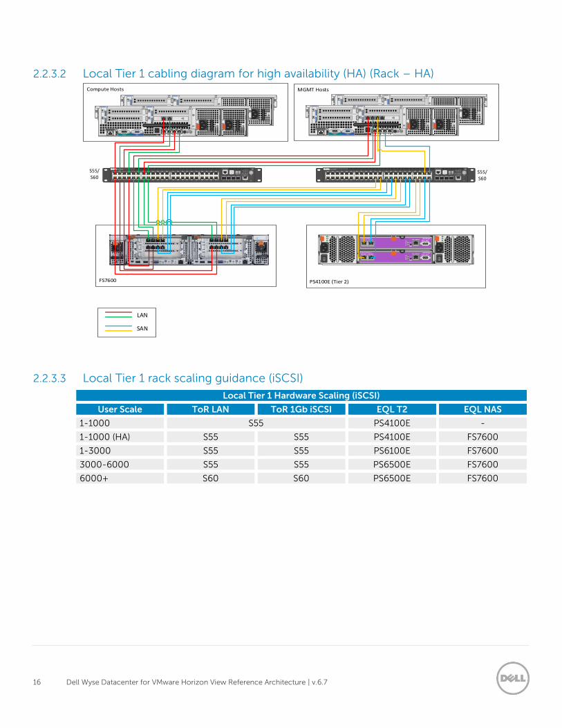
2.2.3.2 Local Tier 1 cabling diagram for high availability (HA) (Rack – HA)
2.2.3.3 Local Tier 1 rack scaling guidance (iSCSI)
Local Tier 1 Hardware Scaling (iSCSI)
User Scale ToR LAN ToR 1Gb iSCSI EQL T2 EQL NAS
1-1000 S55 PS4100E -
1-1000 (HA) S55 S55 PS4100E FS7600
1-3000 S55 S55 PS6100E FS7600
3000-6000 S55 S55 PS6500E FS7600
6000+ S60 S60 PS6500E FS7600
SAN
LAN
S55/S60
S55/S60
17 Dell Wyse Datacenter for VMware Horizon View Reference Architecture | v.6.7
2.3 Shared Tier 1 – Rack
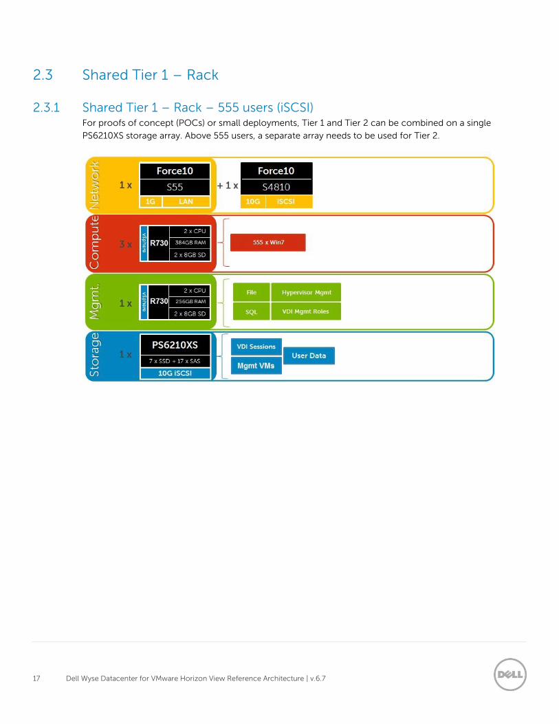
2.3.1 Shared Tier 1 – Rack – 555 users (iSCSI) For proofs of concept (POCs) or small deployments, Tier 1 and Tier 2 can be combined on a single
PS6210XS storage array. Above 555 users, a separate array needs to be used for Tier 2.
18 Dell Wyse Datacenter for VMware Horizon View Reference Architecture | v.6.7
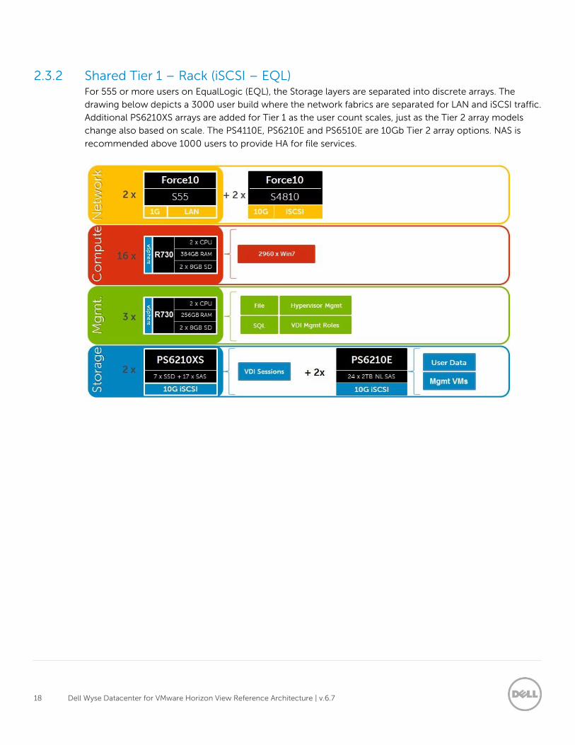
2.3.2 Shared Tier 1 – Rack (iSCSI – EQL) For 555 or more users on EqualLogic (EQL), the Storage layers are separated into discrete arrays. The
drawing below depicts a 3000 user build where the network fabrics are separated for LAN and iSCSI traffic.
Additional PS6210XS arrays are added for Tier 1 as the user count scales, just as the Tier 2 array models
change also based on scale. The PS4110E, PS6210E and PS6510E are 10Gb Tier 2 array options. NAS is
recommended above 1000 users to provide HA for file services.
19 Dell Wyse Datacenter for VMware Horizon View Reference Architecture | v.6.7
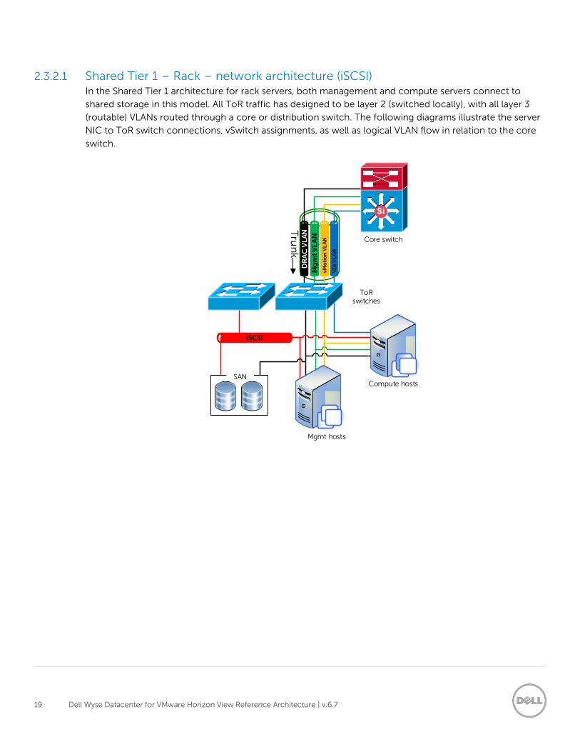
2.3.2.1 Shared Tier 1 – Rack – network architecture (iSCSI) In the Shared Tier 1 architecture for rack servers, both management and compute servers connect to
shared storage in this model. All ToR traffic has designed to be layer 2 (switched locally), with all layer 3
(routable) VLANs routed through a core or distribution switch. The following diagrams illustrate the server
NIC to ToR switch connections, vSwitch assignments, as well as logical VLAN flow in relation to the core
switch.
DR
AC
VL
AN
Mg
mt
VL
AN
iSCSI
Mgmt hosts
Compute hosts
Core switch
ToR switches
Tru
nk
SAN
vMo
tio
n V
LA
N
VD
I VLA
N
20 Dell Wyse Datacenter for VMware Horizon View Reference Architecture | v.6.7
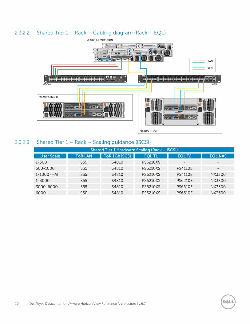
2.3.2.2 Shared Tier 1 – Rack – Cabling diagram (Rack – EQL)
2.3.2.3 Shared Tier 1 – Rack – Scaling guidance (iSCSI)
Shared Tier 1 Hardware Scaling (Rack – iSCSI)
User Scale ToR LAN ToR 1Gb iSCSI EQL T1 EQL T2 EQL NAS
1-500 S55 S4810 PS6210XS - -
500-1000 S55 S4810 PS6210XS PS4110E -
1-1000 (HA) S55 S4810 PS6210XS PS4110E NX3300
1-3000 S55 S4810 PS6210XS PS6210E NX3300
3000-6000 S55 S4810 PS6210XS PS6510E NX3300
6000+ S60 S4810 PS6210XS PS6510E NX3300
SAN
LAN
S4810S55/S60
21 Dell Wyse Datacenter for VMware Horizon View Reference Architecture | v.6.7
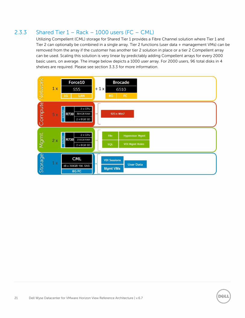
2.3.3 Shared Tier 1 – Rack – 1000 users (FC – CML) Utilizing Compellent (CML) storage for Shared Tier 1 provides a Fibre Channel solution where Tier 1 and
Tier 2 can optionally be combined in a single array. Tier 2 functions (user data + management VMs) can be
removed from the array if the customer has another tier 2 solution in place or a tier 2 Compellent array
can be used. Scaling this solution is very linear by predictably adding Compellent arrays for every 2000
basic users, on average. The image below depicts a 1000 user array. For 2000 users, 96 total disks in 4
shelves are required. Please see section 3.3.3 for more information.
22 Dell Wyse Datacenter for VMware Horizon View Reference Architecture | v.6.7
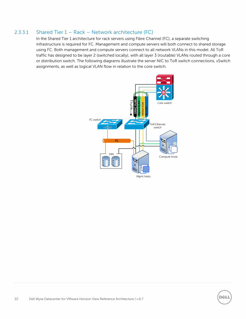
2.3.3.1 Shared Tier 1 – Rack – Network architecture (FC) In the Shared Tier 1 architecture for rack servers using Fibre Channel (FC), a separate switching
infrastructure is required for FC. Management and compute servers will both connect to shared storage
using FC. Both management and compute servers connect to all network VLANs in this model. All ToR
traffic has designed to be layer 2 (switched locally), with all layer 3 (routable) VLANs routed through a core
or distribution switch. The following diagrams illustrate the server NIC to ToR switch connections, vSwitch
assignments, as well as logical VLAN flow in relation to the core switch.
DR
AC
VL
AN
Mg
mt
VL
AN
FC
Mgmt hosts
Compute hosts
Core switch
Tru
nk
SAN
VD
I VL
AN
ToR Ethernet switch
vM
oti
on
VL
AN
FC switch
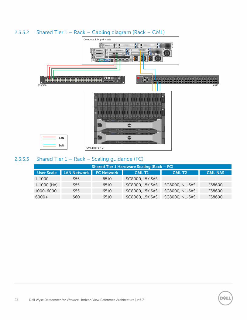
23 Dell Wyse Datacenter for VMware Horizon View Reference Architecture | v.6.7
2.3.3.2 Shared Tier 1 – Rack – Cabling diagram (Rack – CML)
2.3.3.3 Shared Tier 1 – Rack – Scaling guidance (FC)
Shared Tier 1 Hardware Scaling (Rack – FC)
User Scale LAN Network FC Network CML T1 CML T2 CML NAS
1-1000 S55 6510 SC8000, 15K SAS - -
1-1000 (HA) S55 6510 SC8000, 15K SAS SC8000, NL-SAS FS8600
1000-6000 S55 6510 SC8000, 15K SAS SC8000, NL-SAS FS8600
6000+ S60 6510 SC8000, 15K SAS SC8000, NL-SAS FS8600
SAN
LAN
6510S55/S60
24 Dell Wyse Datacenter for VMware Horizon View Reference Architecture | v.6.7
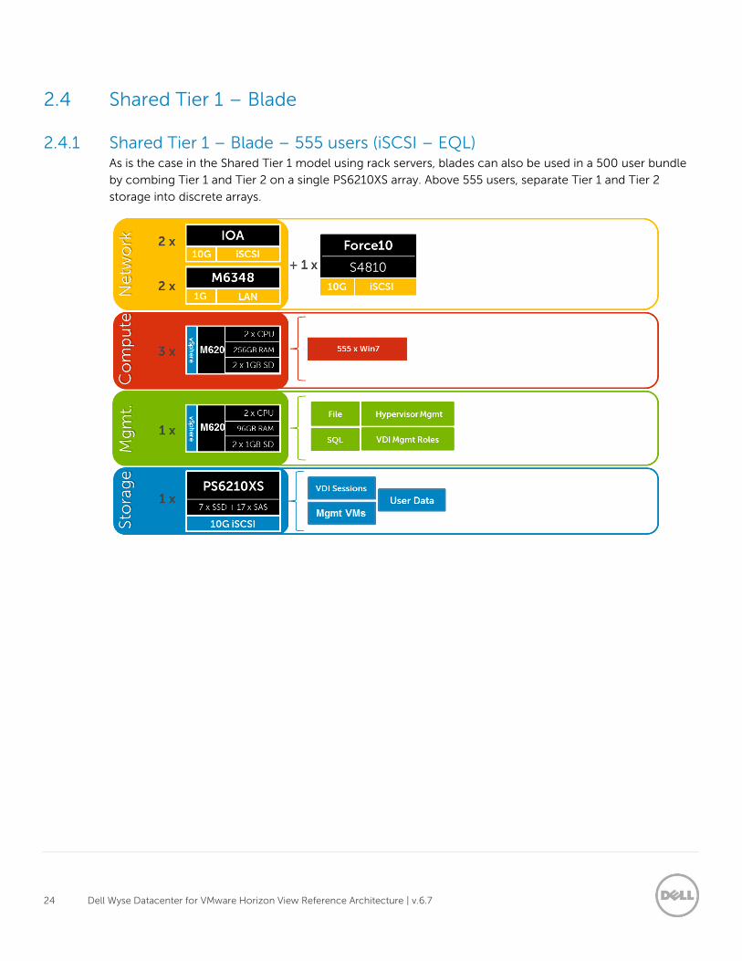
2.4 Shared Tier 1 – Blade
2.4.1 Shared Tier 1 – Blade – 555 users (iSCSI – EQL) As is the case in the Shared Tier 1 model using rack servers, blades can also be used in a 500 user bundle
by combing Tier 1 and Tier 2 on a single PS6210XS array. Above 555 users, separate Tier 1 and Tier 2
storage into discrete arrays.
25 Dell Wyse Datacenter for VMware Horizon View Reference Architecture | v.6.7
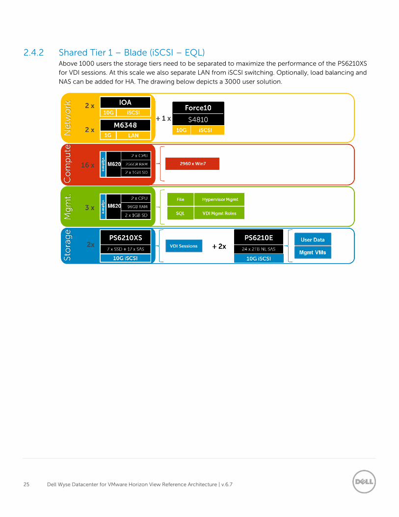
2.4.2 Shared Tier 1 – Blade (iSCSI – EQL) Above 1000 users the storage tiers need to be separated to maximize the performance of the PS6210XS
for VDI sessions. At this scale we also separate LAN from iSCSI switching. Optionally, load balancing and
NAS can be added for HA. The drawing below depicts a 3000 user solution.
26 Dell Wyse Datacenter for VMware Horizon View Reference Architecture | v.6.7
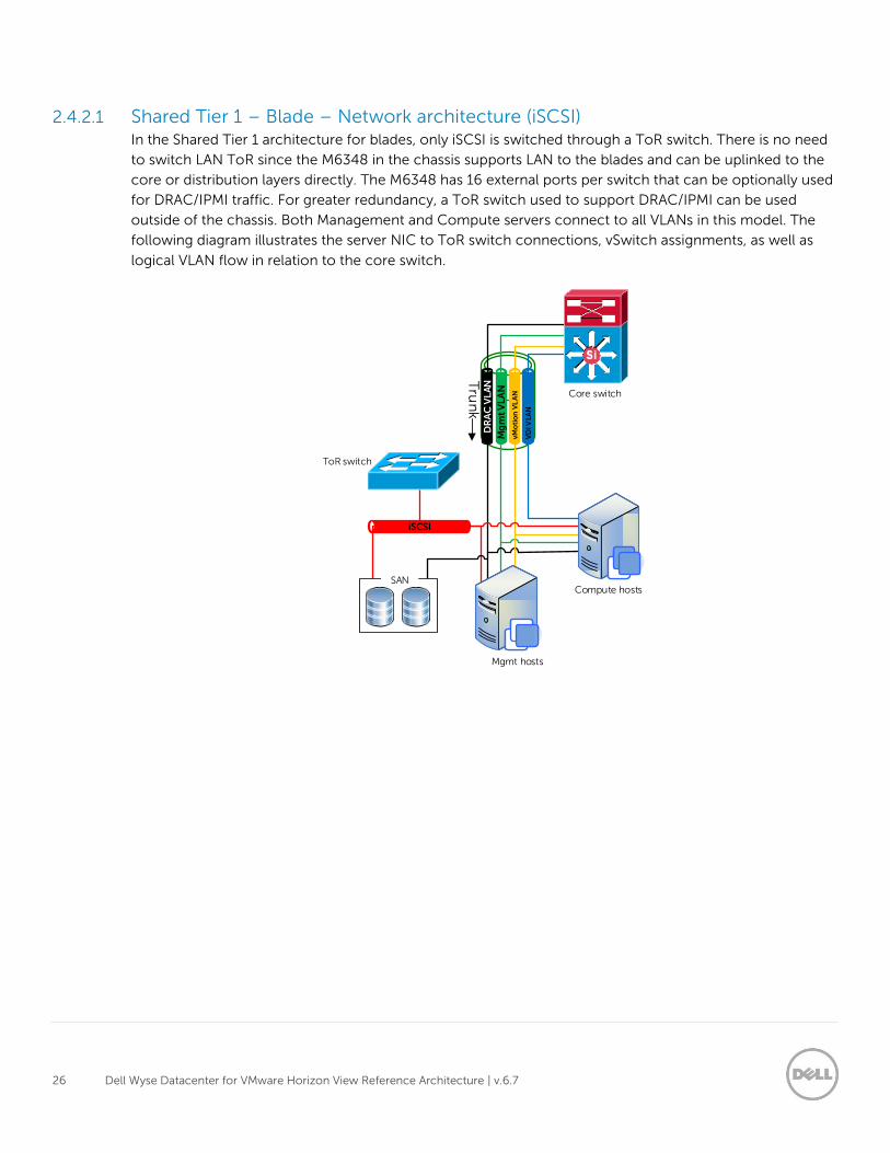
2.4.2.1 Shared Tier 1 – Blade – Network architecture (iSCSI) In the Shared Tier 1 architecture for blades, only iSCSI is switched through a ToR switch. There is no need
to switch LAN ToR since the M6348 in the chassis supports LAN to the blades and can be uplinked to the
core or distribution layers directly. The M6348 has 16 external ports per switch that can be optionally used
for DRAC/IPMI traffic. For greater redundancy, a ToR switch used to support DRAC/IPMI can be used
outside of the chassis. Both Management and Compute servers connect to all VLANs in this model. The
following diagram illustrates the server NIC to ToR switch connections, vSwitch assignments, as well as
logical VLAN flow in relation to the core switch.
DR
AC
VL
AN
Mg
mt
VL
AN
iSCSI
Mgmt hosts
Compute hosts
Core switch
ToR switch
Tru
nk
SAN
vMo
tio
n V
LA
N
VD
I VLA
N
27 Dell Wyse Datacenter for VMware Horizon View Reference Architecture | v.6.7
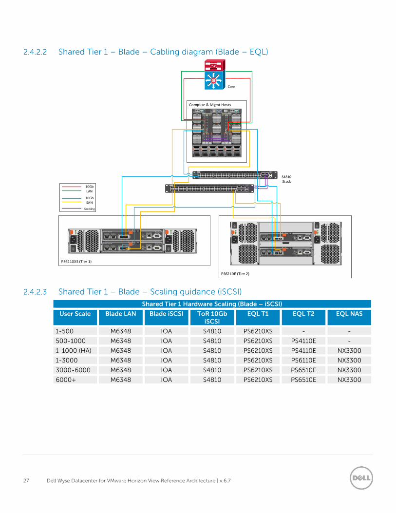
2.4.2.2 Shared Tier 1 – Blade – Cabling diagram (Blade – EQL)
2.4.2.3 Shared Tier 1 – Blade – Scaling guidance (iSCSI)
Shared Tier 1 Hardware Scaling (Blade – iSCSI)
User Scale Blade LAN Blade iSCSI ToR 10Gb iSCSI
EQL T1 EQL T2 EQL NAS
1-500 M6348 IOA S4810 PS6210XS - -
500-1000 M6348 IOA S4810 PS6210XS PS4110E -
1-1000 (HA) M6348 IOA S4810 PS6210XS PS4110E NX3300
1-3000 M6348 IOA S4810 PS6210XS PS6110E NX3300
3000-6000 M6348 IOA S4810 PS6210XS PS6510E NX3300
6000+ M6348 IOA S4810 PS6210XS PS6510E NX3300
S4810 Stack
Core
10Gb SAN
10Gb LAN
Stacking
28 Dell Wyse Datacenter for VMware Horizon View Reference Architecture | v.6.7
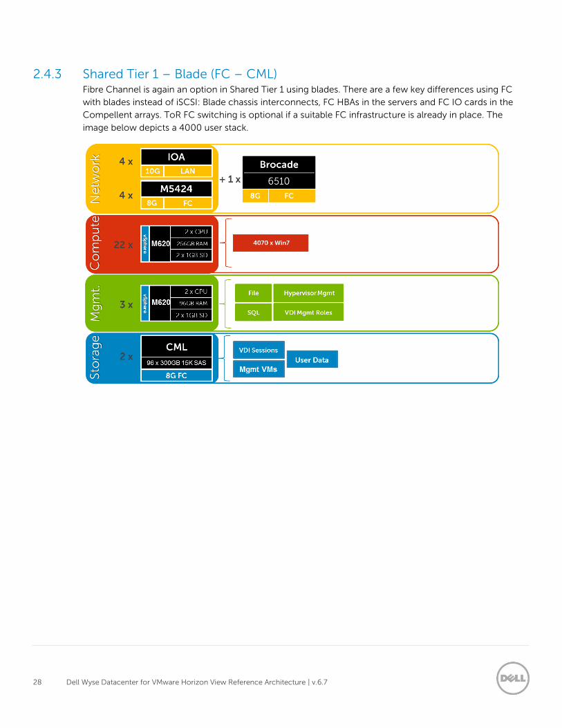
2.4.3 Shared Tier 1 – Blade (FC – CML) Fibre Channel is again an option in Shared Tier 1 using blades. There are a few key differences using FC
with blades instead of iSCSI: Blade chassis interconnects, FC HBAs in the servers and FC IO cards in the
Compellent arrays. ToR FC switching is optional if a suitable FC infrastructure is already in place. The
image below depicts a 4000 user stack.
29 Dell Wyse Datacenter for VMware Horizon View Reference Architecture | v.6.7
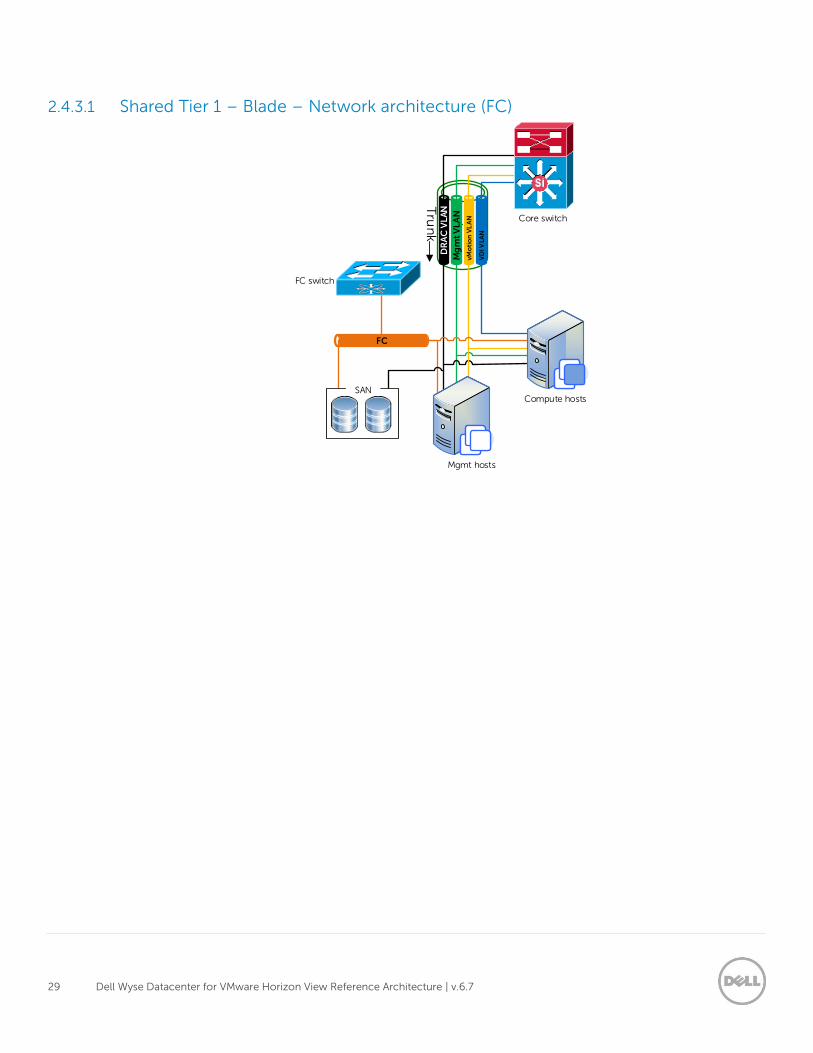
2.4.3.1 Shared Tier 1 – Blade – Network architecture (FC)
DR
AC
VL
AN
Mg
mt
VL
AN
FC
Mgmt hosts
Compute hosts
Core switch
FC switch
Tru
nk
SAN
vM
oti
on
VL
AN
VD
I VL
AN
30 Dell Wyse Datacenter for VMware Horizon View Reference Architecture | v.6.7
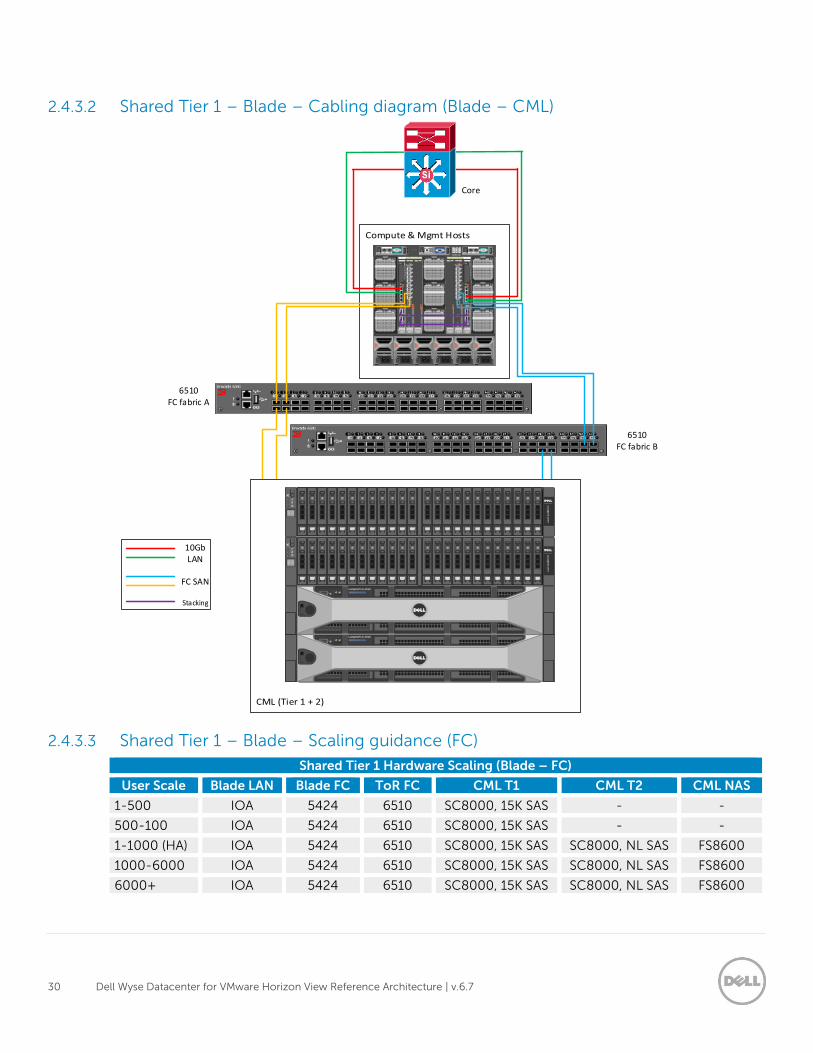
2.4.3.2 Shared Tier 1 – Blade – Cabling diagram (Blade – CML)
2.4.3.3 Shared Tier 1 – Blade – Scaling guidance (FC)
Shared Tier 1 Hardware Scaling (Blade – FC)
User Scale Blade LAN Blade FC ToR FC CML T1 CML T2 CML NAS
1-500 IOA 5424 6510 SC8000, 15K SAS - -
500-100 IOA 5424 6510 SC8000, 15K SAS - -
1-1000 (HA) IOA 5424 6510 SC8000, 15K SAS SC8000, NL SAS FS8600
1000-6000 IOA 5424 6510 SC8000, 15K SAS SC8000, NL SAS FS8600
6000+ IOA 5424 6510 SC8000, 15K SAS SC8000, NL SAS FS8600
6510FC fabric A
Core
6510FC fabric B
FC SAN
10Gb LAN
Stacking
31 Dell Wyse Datacenter for VMware Horizon View Reference Architecture | v.6.7
3 Hardware components
3.1 Networking The following sections contain the core network components for the Dell Wyse Datacenter solutions.
General uplink cabling guidance to consider in all cases is that Twinax is very cost effective for short 10Gb
runs and for longer runs it is best to use fiber with SFPs.
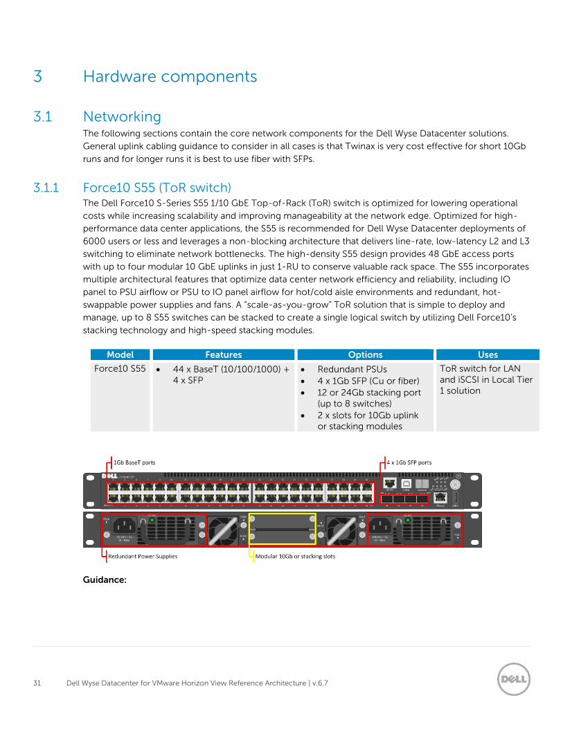
3.1.1 Force10 S55 (ToR switch) The Dell Force10 S-Series S55 1/10 GbE Top-of-Rack (ToR) switch is optimized for lowering operational
costs while increasing scalability and improving manageability at the network edge. Optimized for high-
performance data center applications, the S55 is recommended for Dell Wyse Datacenter deployments of
6000 users or less and leverages a non-blocking architecture that delivers line-rate, low-latency L2 and L3
switching to eliminate network bottlenecks. The high-density S55 design provides 48 GbE access ports
with up to four modular 10 GbE uplinks in just 1-RU to conserve valuable rack space. The S55 incorporates
multiple architectural features that optimize data center network efficiency and reliability, including IO
panel to PSU airflow or PSU to IO panel airflow for hot/cold aisle environments and redundant, hot-
swappable power supplies and fans. A “scale-as-you-grow” ToR solution that is simple to deploy and
manage, up to 8 S55 switches can be stacked to create a single logical switch by utilizing Dell Force10’s
stacking technology and high-speed stacking modules.
Model Features Options Uses
Force10 S55 44 x BaseT (10/100/1000) + 4 x SFP
Redundant PSUs
4 x 1Gb SFP (Cu or fiber)
12 or 24Gb stacking port (up to 8 switches)
2 x slots for 10Gb uplink or stacking modules
ToR switch for LAN and iSCSI in Local Tier 1 solution
Guidance:
32 Dell Wyse Datacenter for VMware Horizon View Reference Architecture | v.6.7
10Gb uplinks to a core or distribution switch are the preferred design choice using the rear 10Gb
uplink modules. If 10Gb to a core or distribution switch is unavailable the front 4 x 1Gb SFP ports
can be used.
The front 4 SFP ports can support copper cabling and can be upgraded to optical if a longer run is
needed.
For more information on the S55 switch and Dell Force10 networking, please visit:
http://www.dell.com/us/enterprise/p/force10-s55/pd
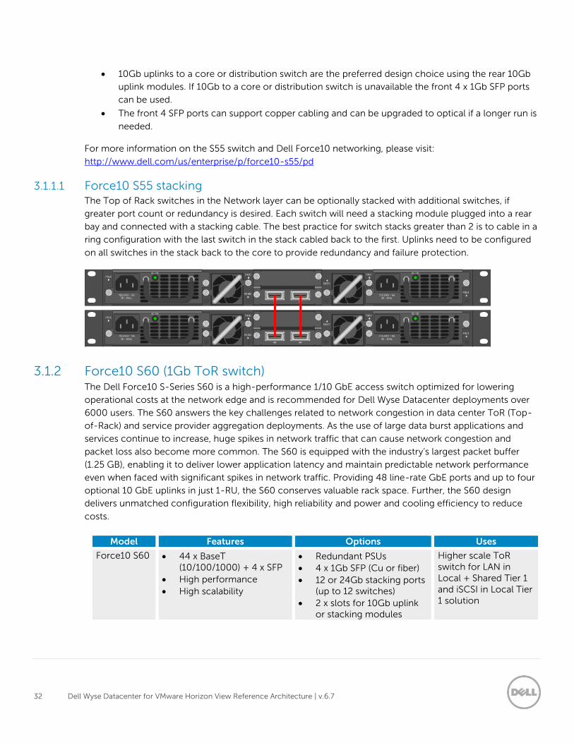
3.1.1.1 Force10 S55 stacking The Top of Rack switches in the Network layer can be optionally stacked with additional switches, if
greater port count or redundancy is desired. Each switch will need a stacking module plugged into a rear
bay and connected with a stacking cable. The best practice for switch stacks greater than 2 is to cable in a
ring configuration with the last switch in the stack cabled back to the first. Uplinks need to be configured
on all switches in the stack back to the core to provide redundancy and failure protection.
3.1.2 Force10 S60 (1Gb ToR switch) The Dell Force10 S-Series S60 is a high-performance 1/10 GbE access switch optimized for lowering
operational costs at the network edge and is recommended for Dell Wyse Datacenter deployments over
6000 users. The S60 answers the key challenges related to network congestion in data center ToR (Top-
of-Rack) and service provider aggregation deployments. As the use of large data burst applications and
services continue to increase, huge spikes in network traffic that can cause network congestion and
packet loss also become more common. The S60 is equipped with the industry’s largest packet buffer
(1.25 GB), enabling it to deliver lower application latency and maintain predictable network performance
even when faced with significant spikes in network traffic. Providing 48 line-rate GbE ports and up to four
optional 10 GbE uplinks in just 1-RU, the S60 conserves valuable rack space. Further, the S60 design
delivers unmatched configuration flexibility, high reliability and power and cooling efficiency to reduce
costs.
Model Features Options Uses
Force10 S60 44 x BaseT (10/100/1000) + 4 x SFP
High performance
High scalability
Redundant PSUs
4 x 1Gb SFP (Cu or fiber)
12 or 24Gb stacking ports (up to 12 switches)
2 x slots for 10Gb uplink or stacking modules
Higher scale ToR switch for LAN in Local + Shared Tier 1 and iSCSI in Local Tier 1 solution
33 Dell Wyse Datacenter for VMware Horizon View Reference Architecture | v.6.7
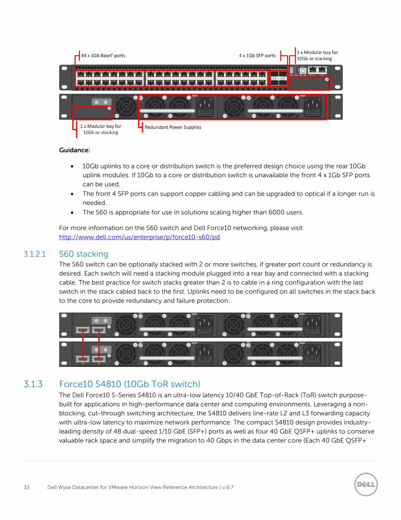
Guidance:
10Gb uplinks to a core or distribution switch is the preferred design choice using the rear 10Gb
uplink modules. If 10Gb to a core or distribution switch is unavailable the front 4 x 1Gb SFP ports
can be used.
The front 4 SFP ports can support copper cabling and can be upgraded to optical if a longer run is
needed.
The S60 is appropriate for use in solutions scaling higher than 6000 users.
For more information on the S60 switch and Dell Force10 networking, please visit:
http://www.dell.com/us/enterprise/p/force10-s60/pd
3.1.2.1 S60 stacking The S60 switch can be optionally stacked with 2 or more switches, if greater port count or redundancy is
desired. Each switch will need a stacking module plugged into a rear bay and connected with a stacking
cable. The best practice for switch stacks greater than 2 is to cable in a ring configuration with the last
switch in the stack cabled back to the first. Uplinks need to be configured on all switches in the stack back
to the core to provide redundancy and failure protection.
3.1.3 Force10 S4810 (10Gb ToR switch) The Dell Force10 S-Series S4810 is an ultra-low latency 10/40 GbE Top-of-Rack (ToR) switch purpose-
built for applications in high-performance data center and computing environments. Leveraging a non-
blocking, cut-through switching architecture, the S4810 delivers line-rate L2 and L3 forwarding capacity
with ultra-low latency to maximize network performance. The compact S4810 design provides industry-
leading density of 48 dual-speed 1/10 GbE (SFP+) ports as well as four 40 GbE QSFP+ uplinks to conserve
valuable rack space and simplify the migration to 40 Gbps in the data center core (Each 40 GbE QSFP+
34 Dell Wyse Datacenter for VMware Horizon View Reference Architecture | v.6.7
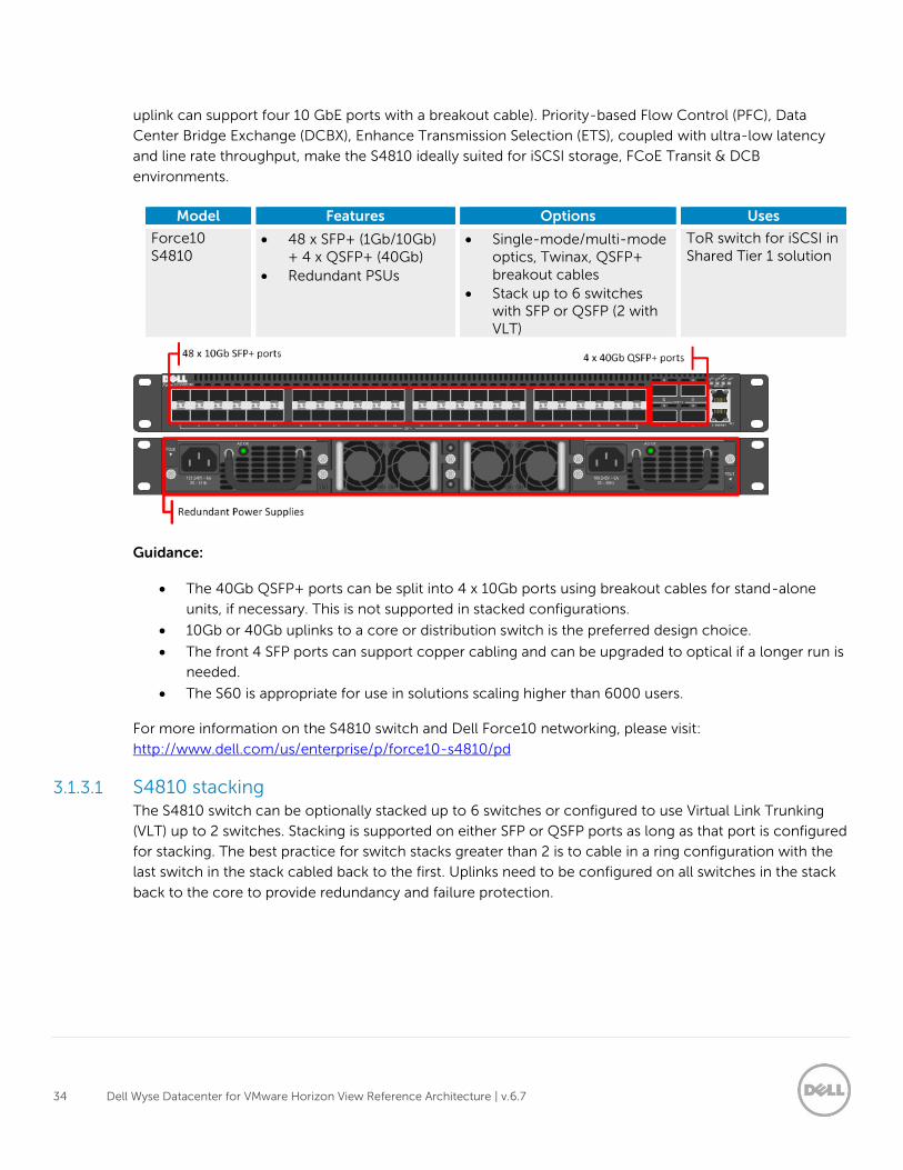
uplink can support four 10 GbE ports with a breakout cable). Priority-based Flow Control (PFC), Data
Center Bridge Exchange (DCBX), Enhance Transmission Selection (ETS), coupled with ultra-low latency
and line rate throughput, make the S4810 ideally suited for iSCSI storage, FCoE Transit & DCB
environments.
Model Features Options Uses
Force10 S4810
48 x SFP+ (1Gb/10Gb) + 4 x QSFP+ (40Gb)
Redundant PSUs
Single-mode/multi-mode optics, Twinax, QSFP+ breakout cables
Stack up to 6 switches with SFP or QSFP (2 with VLT)
ToR switch for iSCSI in Shared Tier 1 solution
Guidance:
The 40Gb QSFP+ ports can be split into 4 x 10Gb ports using breakout cables for stand-alone
units, if necessary. This is not supported in stacked configurations.
10Gb or 40Gb uplinks to a core or distribution switch is the preferred design choice.
The front 4 SFP ports can support copper cabling and can be upgraded to optical if a longer run is
needed.
The S60 is appropriate for use in solutions scaling higher than 6000 users.
For more information on the S4810 switch and Dell Force10 networking, please visit:
http://www.dell.com/us/enterprise/p/force10-s4810/pd
3.1.3.1 S4810 stacking The S4810 switch can be optionally stacked up to 6 switches or configured to use Virtual Link Trunking
(VLT) up to 2 switches. Stacking is supported on either SFP or QSFP ports as long as that port is configured
for stacking. The best practice for switch stacks greater than 2 is to cable in a ring configuration with the
last switch in the stack cabled back to the first. Uplinks need to be configured on all switches in the stack
back to the core to provide redundancy and failure protection.
35 Dell Wyse Datacenter for VMware Horizon View Reference Architecture | v.6.7
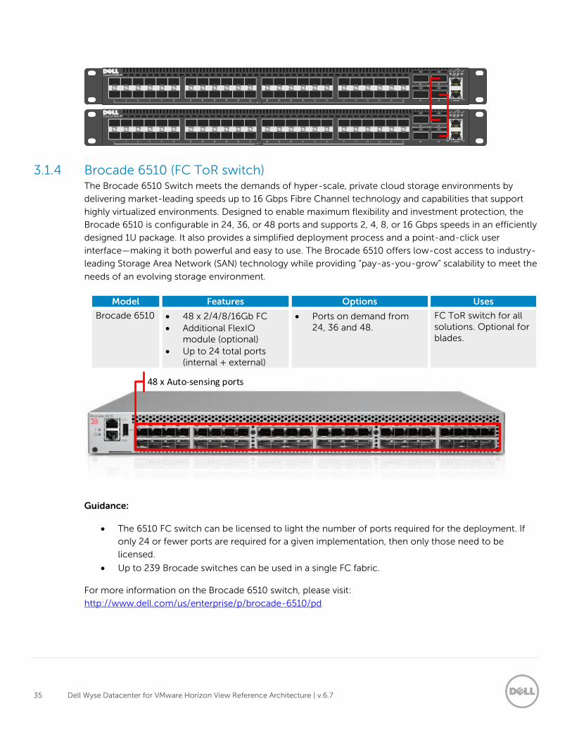
3.1.4 Brocade 6510 (FC ToR switch) The Brocade 6510 Switch meets the demands of hyper-scale, private cloud storage environments by
delivering market-leading speeds up to 16 Gbps Fibre Channel technology and capabilities that support
highly virtualized environments. Designed to enable maximum flexibility and investment protection, the
Brocade 6510 is configurable in 24, 36, or 48 ports and supports 2, 4, 8, or 16 Gbps speeds in an efficiently
designed 1U package. It also provides a simplified deployment process and a point-and-click user
interface—making it both powerful and easy to use. The Brocade 6510 offers low-cost access to industry-
leading Storage Area Network (SAN) technology while providing “pay-as-you-grow” scalability to meet the
needs of an evolving storage environment.
Model Features Options Uses
Brocade 6510 48 x 2/4/8/16Gb FC
Additional FlexIO module (optional)
Up to 24 total ports (internal + external)
Ports on demand from 24, 36 and 48.
FC ToR switch for all solutions. Optional for blades.
Guidance:
The 6510 FC switch can be licensed to light the number of ports required for the deployment. If
only 24 or fewer ports are required for a given implementation, then only those need to be
licensed.
Up to 239 Brocade switches can be used in a single FC fabric.
For more information on the Brocade 6510 switch, please visit:
http://www.dell.com/us/enterprise/p/brocade-6510/pd
48 x Auto-sensing ports
36 Dell Wyse Datacenter for VMware Horizon View Reference Architecture | v.6.7
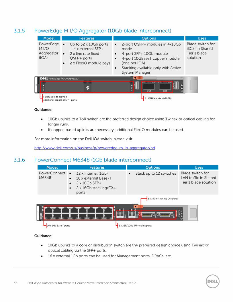
3.1.5 PowerEdge M I/O Aggregator (10Gb blade interconnect)
Model Features Options Uses
PowerEdge M I/O Aggregator (IOA)
Up to 32 x 10Gb ports + 4 x external SFP+
2 x line rate fixed QSFP+ ports
2 x FlexIO module bays
2-port QSFP+ modules in 4x10Gb mode
4-port SFP+ 10Gb module
4-port 10GBaseT copper module (one per IOA)
Stacking available only with Active System Manager
Blade switch for iSCSI in Shared Tier 1 blade solution
Guidance:
10Gb uplinks to a ToR switch are the preferred design choice using Twinax or optical cabling for
longer runs.
If copper-based uplinks are necessary, additional FlexIO modules can be used.
For more information on the Dell IOA switch, please visit:
http://www.dell.com/us/business/p/poweredge-m-io-aggregator/pd
3.1.6 PowerConnect M6348 (1Gb blade interconnect)
Model Features Options Uses
PowerConnect M6348
32 x internal (1Gb)
16 x external Base-T
2 x 10Gb SFP+
2 x 16Gb stacking/CX4 ports
Stack up to 12 switches Blade switch for LAN traffic in Shared Tier 1 blade solution
Guidance:
10Gb uplinks to a core or distribution switch are the preferred design choice using Twinax or
optical cabling via the SFP+ ports.
16 x external 1Gb ports can be used for Management ports, DRACs, etc.
FlexIO slots to provide additional copper or SFP+ ports
2 x QSFP+ ports (4x10Gb)
XG
2
XG
1
XG
3
CO
NS
OL
E
33
34
LK
M6
34
8
47
48
Ac
t
LK
Ac
t
LK
Ac
t
XG
4
2 x 1Gb/10Gb SFP+ uplink ports16 x 1Gb Base-T ports
2 x 16Gb Stacking/ CX4 ports
37 Dell Wyse Datacenter for VMware Horizon View Reference Architecture | v.6.7
Stack up to 12 switches using stacking ports.
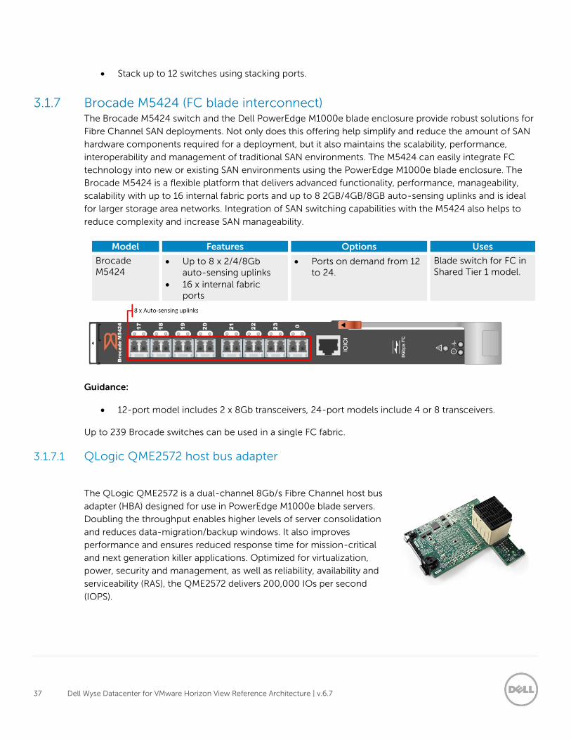
3.1.7 Brocade M5424 (FC blade interconnect) The Brocade M5424 switch and the Dell PowerEdge M1000e blade enclosure provide robust solutions for
Fibre Channel SAN deployments. Not only does this offering help simplify and reduce the amount of SAN
hardware components required for a deployment, but it also maintains the scalability, performance,
interoperability and management of traditional SAN environments. The M5424 can easily integrate FC
technology into new or existing SAN environments using the PowerEdge M1000e blade enclosure. The
Brocade M5424 is a flexible platform that delivers advanced functionality, performance, manageability,
scalability with up to 16 internal fabric ports and up to 8 2GB/4GB/8GB auto-sensing uplinks and is ideal
for larger storage area networks. Integration of SAN switching capabilities with the M5424 also helps to
reduce complexity and increase SAN manageability.
Model Features Options Uses
Brocade M5424
Up to 8 x 2/4/8Gb auto-sensing uplinks
16 x internal fabric ports
Ports on demand from 12 to 24.
Blade switch for FC in Shared Tier 1 model.
Guidance:
12-port model includes 2 x 8Gb transceivers, 24-port models include 4 or 8 transceivers.
Up to 239 Brocade switches can be used in a single FC fabric.
3.1.7.1 QLogic QME2572 host bus adapter
The QLogic QME2572 is a dual-channel 8Gb/s Fibre Channel host bus
adapter (HBA) designed for use in PowerEdge M1000e blade servers.
Doubling the throughput enables higher levels of server consolidation
and reduces data-migration/backup windows. It also improves
performance and ensures reduced response time for mission-critical
and next generation killer applications. Optimized for virtualization,
power, security and management, as well as reliability, availability and
serviceability (RAS), the QME2572 delivers 200,000 IOs per second
(IOPS).
38 Dell Wyse Datacenter for VMware Horizon View Reference Architecture | v.6.7
3.1.7.2 QLogic QLE2562 HBA The QLE2562 is a PCI Express, dual port, Fibre Channel HBA. The QLE2562 is
part of the QLE2500 HBA product family that offers next generation 8 Gb FC
technology, meeting the business requirements of the enterprise data center.
Features of this HBA includes throughput of 3200 MBps (full-duplex), 200,000
initiator and target I/Os per second (IOPS) per port and StarPower technology-
based dynamic and adaptive power management. Benefits include optimizations
for virtualization, power, reliability, availability and serviceability (RAS) and
security.
3.2 Servers
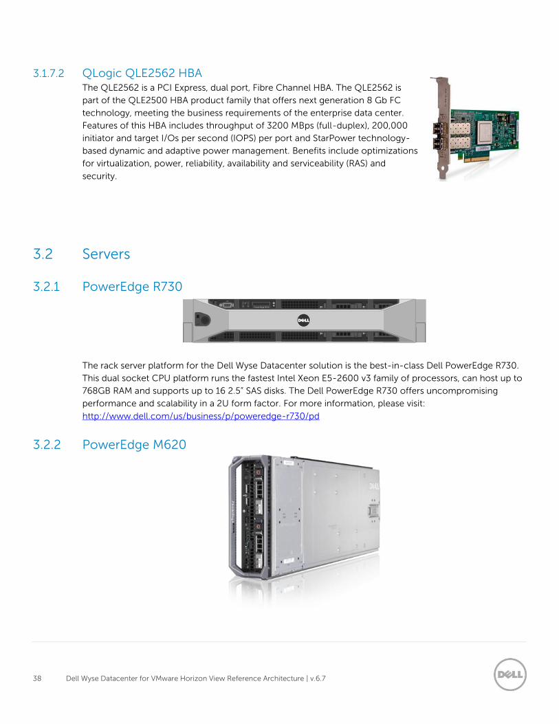
3.2.1 PowerEdge R730
Pow erEdge R720
The rack server platform for the Dell Wyse Datacenter solution is the best-in-class Dell PowerEdge R730.
This dual socket CPU platform runs the fastest Intel Xeon E5-2600 v3 family of processors, can host up to
768GB RAM and supports up to 16 2.5” SAS disks. The Dell PowerEdge R730 offers uncompromising
performance and scalability in a 2U form factor. For more information, please visit:
http://www.dell.com/us/business/p/poweredge-r730/pd
3.2.2 PowerEdge M620
39 Dell Wyse Datacenter for VMware Horizon View Reference Architecture | v.6.7
The blade server platform for the Dell Wyse Datacenter solution is the PowerEdge M620. This half-height
blade server is a feature-rich, dual-processor platform that offers a blend of density, performance,
efficiency and scalability. The M620 offers remarkable computational density, scaling up to 24 cores, 2
socket Intel Xeon processors and 24 DIMMs (768GB RAM) of DDR3 memory in an extremely compact
half-height blade form factor. This server platform is currently offered in both the PowerEdge M1000e
blade enclosure and VRTX shared infrastructure platform. For more information, please visit:
http://www.dell.com/us/business/p/poweredge-m620/pd
3.3 Storage
3.3.1 EqualLogic Tier 1 storage (iSCSI)
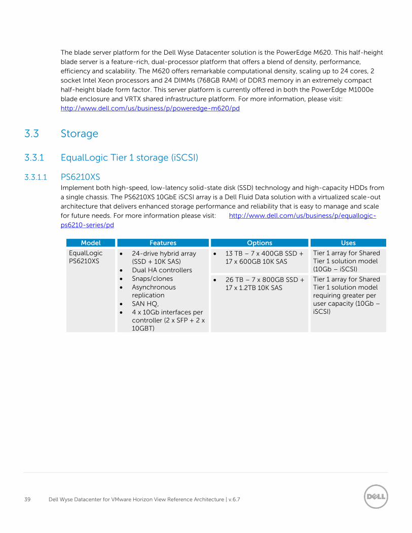
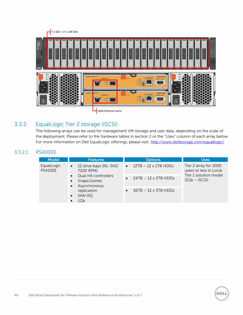
3.3.1.1 PS6210XS Implement both high-speed, low-latency solid-state disk (SSD) technology and high-capacity HDDs from
a single chassis. The PS6210XS 10GbE iSCSI array is a Dell Fluid Data solution with a virtualized scale-out
architecture that delivers enhanced storage performance and reliability that is easy to manage and scale
for future needs. For more information please visit: http://www.dell.com/us/business/p/equallogic-
ps6210-series/pd
Model Features Options Uses
EqualLogic PS6210XS
24-drive hybrid array (SSD + 10K SAS)
Dual HA controllers
Snaps/clones
Asynchronous replication
SAN HQ,
4 x 10Gb interfaces per controller (2 x SFP + 2 x 10GBT)
13 TB – 7 x 400GB SSD + 17 x 600GB 10K SAS
Tier 1 array for Shared Tier 1 solution model (10Gb – iSCSI)
26 TB – 7 x 800GB SSD + 17 x 1.2TB 10K SAS
Tier 1 array for Shared Tier 1 solution model requiring greater per user capacity (10Gb – iSCSI)
40 Dell Wyse Datacenter for VMware Horizon View Reference Architecture | v.6.7
3.3.2 EqualLogic Tier 2 storage (iSCSI) The following arrays can be used for management VM storage and user data, depending on the scale of
the deployment. Please refer to the hardware tables in section 2 or the “Uses” column of each array below.
For more information on Dell EqualLogic offerings, please visit: http://www.dellstorage.com/equallogic/
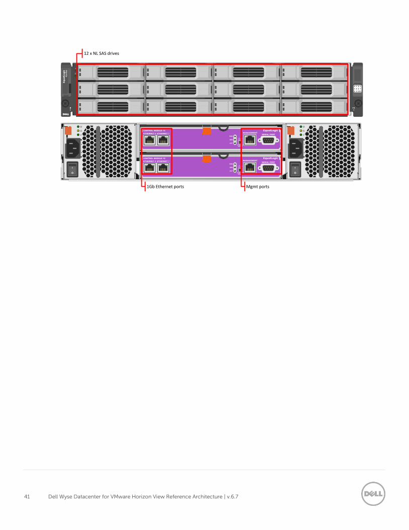
3.3.2.1 PS4100E
Model Features Options Uses
EqualLogic PS4100E
12 drive bays (NL-SAS/ 7200 RPM)
Dual HA controllers
Snaps/clones
Asynchronous replication
SAN HQ
1Gb
12TB – 12 x 1TB HDDs Tier 2 array for 1000 users or less in Local Tier 1 solution model (1Gb – iSCSI) 24TB – 12 x 2TB HDDs
36TB – 12 x 3TB HDDs
7 x SSD + 17 x 10K SAS
10Gb Ethernet ports
41 Dell Wyse Datacenter for VMware Horizon View Reference Architecture | v.6.7
MANAGEMENT
SERIAL PORT
SERIAL PORT
MANAGEMENT
STANDBY
ON/OFF
ACT
ERR
PWR
ACT
ERR
PWR
STANDBY
ON/OFF
ETHERNET 1
ETHERNET 1
ETHERNET 0
CONTROL MODULE 12
ETHERNET 0
CONTROL MODULE 12
0
4
8
1
5
9
2
6
10
3
7
11
Hard Drives
1Gb Ethernet ports Mgmt ports
12 x NL SAS drives
42 Dell Wyse Datacenter for VMware Horizon View Reference Architecture | v.6.7
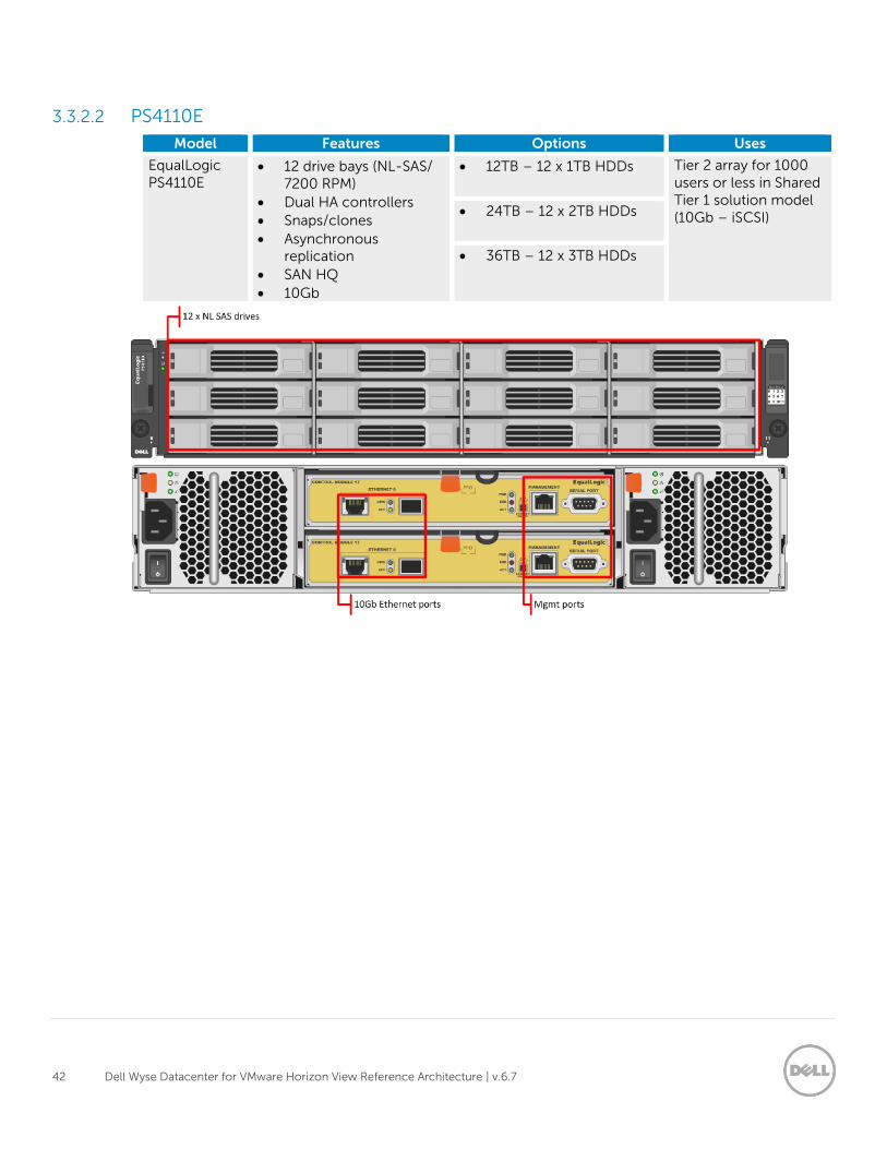
3.3.2.2 PS4110E
Model Features Options Uses
EqualLogic PS4110E
12 drive bays (NL-SAS/ 7200 RPM)
Dual HA controllers
Snaps/clones
Asynchronous replication
SAN HQ
10Gb
12TB – 12 x 1TB HDDs Tier 2 array for 1000 users or less in Shared Tier 1 solution model (10Gb – iSCSI) 24TB – 12 x 2TB HDDs
36TB – 12 x 3TB HDDs
43 Dell Wyse Datacenter for VMware Horizon View Reference Architecture | v.6.7
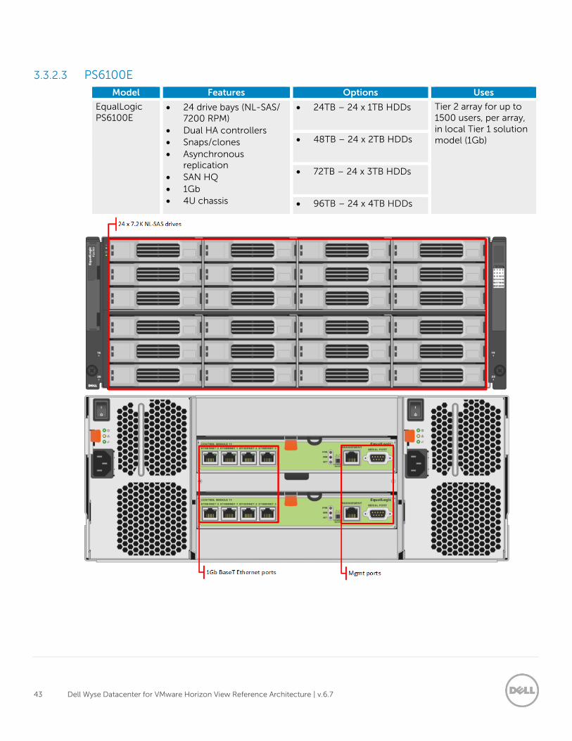
3.3.2.3 PS6100E
Model Features Options Uses
EqualLogic PS6100E
24 drive bays (NL-SAS/ 7200 RPM)
Dual HA controllers
Snaps/clones
Asynchronous replication
SAN HQ
1Gb
4U chassis
24TB – 24 x 1TB HDDs Tier 2 array for up to 1500 users, per array, in local Tier 1 solution model (1Gb) 48TB – 24 x 2TB HDDs
72TB – 24 x 3TB HDDs
96TB – 24 x 4TB HDDs
44 Dell Wyse Datacenter for VMware Horizon View Reference Architecture | v.6.7
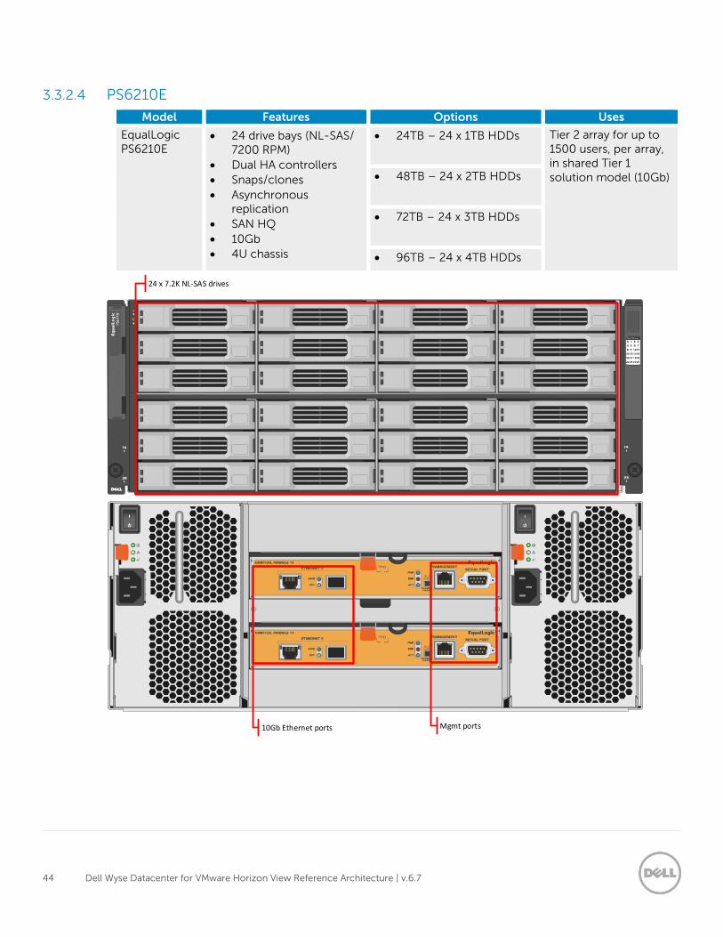
3.3.2.4 PS6210E
Model Features Options Uses
EqualLogic PS6210E
24 drive bays (NL-SAS/ 7200 RPM)
Dual HA controllers
Snaps/clones
Asynchronous replication
SAN HQ
10Gb
4U chassis
24TB – 24 x 1TB HDDs Tier 2 array for up to 1500 users, per array, in shared Tier 1 solution model (10Gb) 48TB – 24 x 2TB HDDs
72TB – 24 x 3TB HDDs
96TB – 24 x 4TB HDDs
24 x 7.2K NL-SAS drives
10Gb Ethernet ports Mgmt ports
45 Dell Wyse Datacenter for VMware Horizon View Reference Architecture | v.6.7
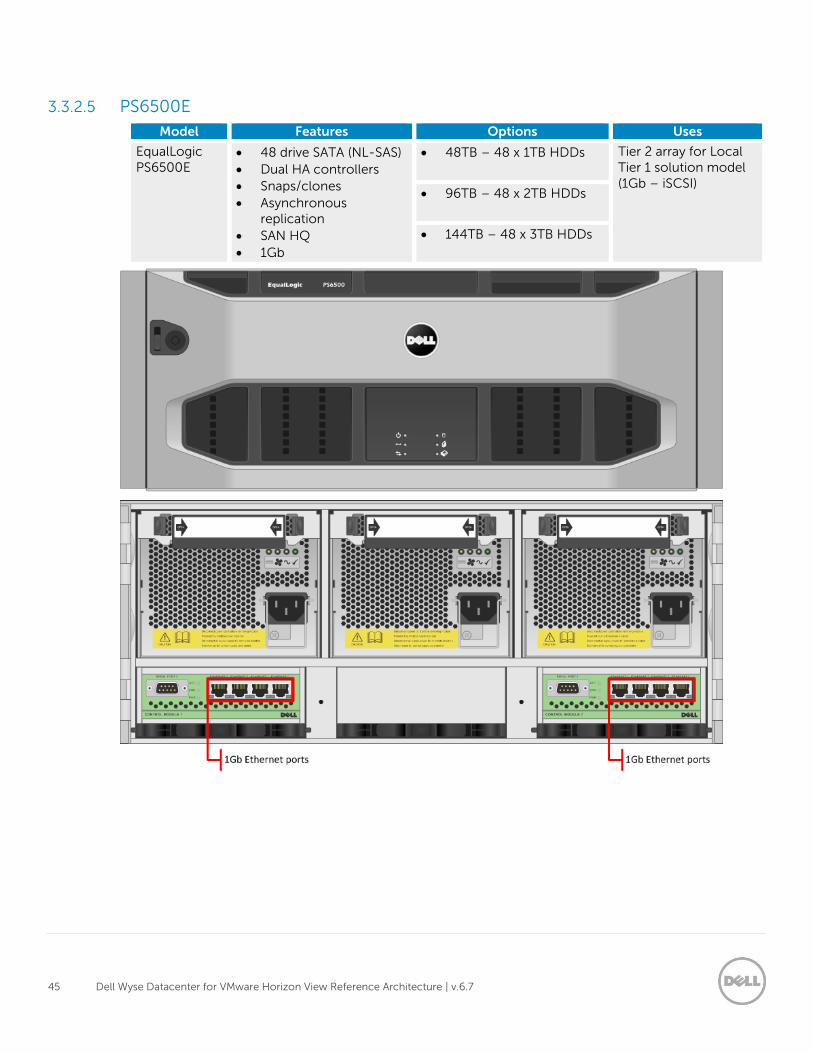
3.3.2.5 PS6500E
Model Features Options Uses
EqualLogic PS6500E
48 drive SATA (NL-SAS)
Dual HA controllers
Snaps/clones
Asynchronous replication
SAN HQ
1Gb
48TB – 48 x 1TB HDDs Tier 2 array for Local Tier 1 solution model (1Gb – iSCSI)
96TB – 48 x 2TB HDDs
144TB – 48 x 3TB HDDs
46 Dell Wyse Datacenter for VMware Horizon View Reference Architecture | v.6.7
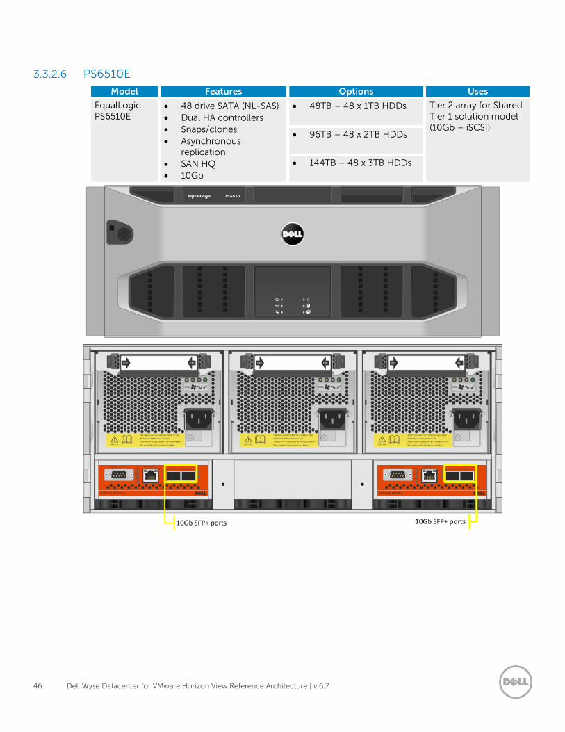
3.3.2.6 PS6510E
Model Features Options Uses
EqualLogic PS6510E
48 drive SATA (NL-SAS)
Dual HA controllers
Snaps/clones
Asynchronous replication
SAN HQ
10Gb
48TB – 48 x 1TB HDDs Tier 2 array for Shared Tier 1 solution model (10Gb – iSCSI)
96TB – 48 x 2TB HDDs
144TB – 48 x 3TB HDDs
47 Dell Wyse Datacenter for VMware Horizon View Reference Architecture | v.6.7
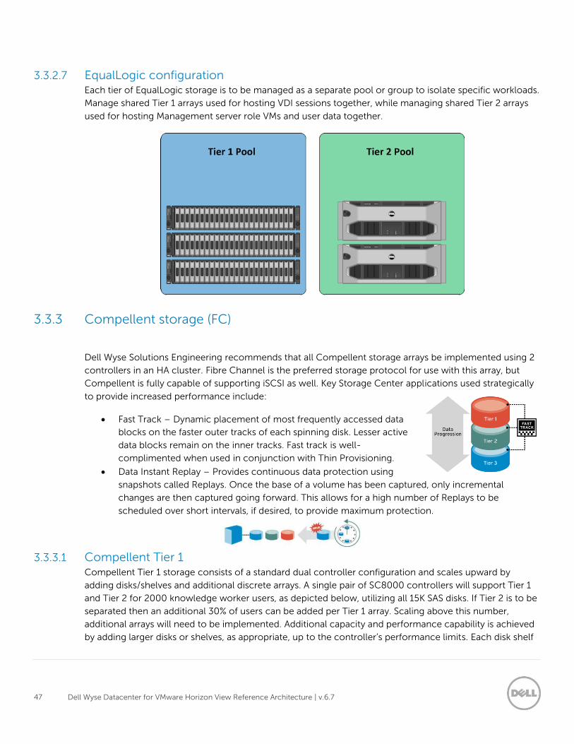
3.3.2.7 EqualLogic configuration Each tier of EqualLogic storage is to be managed as a separate pool or group to isolate specific workloads.
Manage shared Tier 1 arrays used for hosting VDI sessions together, while managing shared Tier 2 arrays
used for hosting Management server role VMs and user data together.
3.3.3 Compellent storage (FC)
Dell Wyse Solutions Engineering recommends that all Compellent storage arrays be implemented using 2
controllers in an HA cluster. Fibre Channel is the preferred storage protocol for use with this array, but
Compellent is fully capable of supporting iSCSI as well. Key Storage Center applications used strategically
to provide increased performance include:
Fast Track – Dynamic placement of most frequently accessed data
blocks on the faster outer tracks of each spinning disk. Lesser active
data blocks remain on the inner tracks. Fast track is well-
complimented when used in conjunction with Thin Provisioning.
Data Instant Replay – Provides continuous data protection using
snapshots called Replays. Once the base of a volume has been captured, only incremental
changes are then captured going forward. This allows for a high number of Replays to be
scheduled over short intervals, if desired, to provide maximum protection.
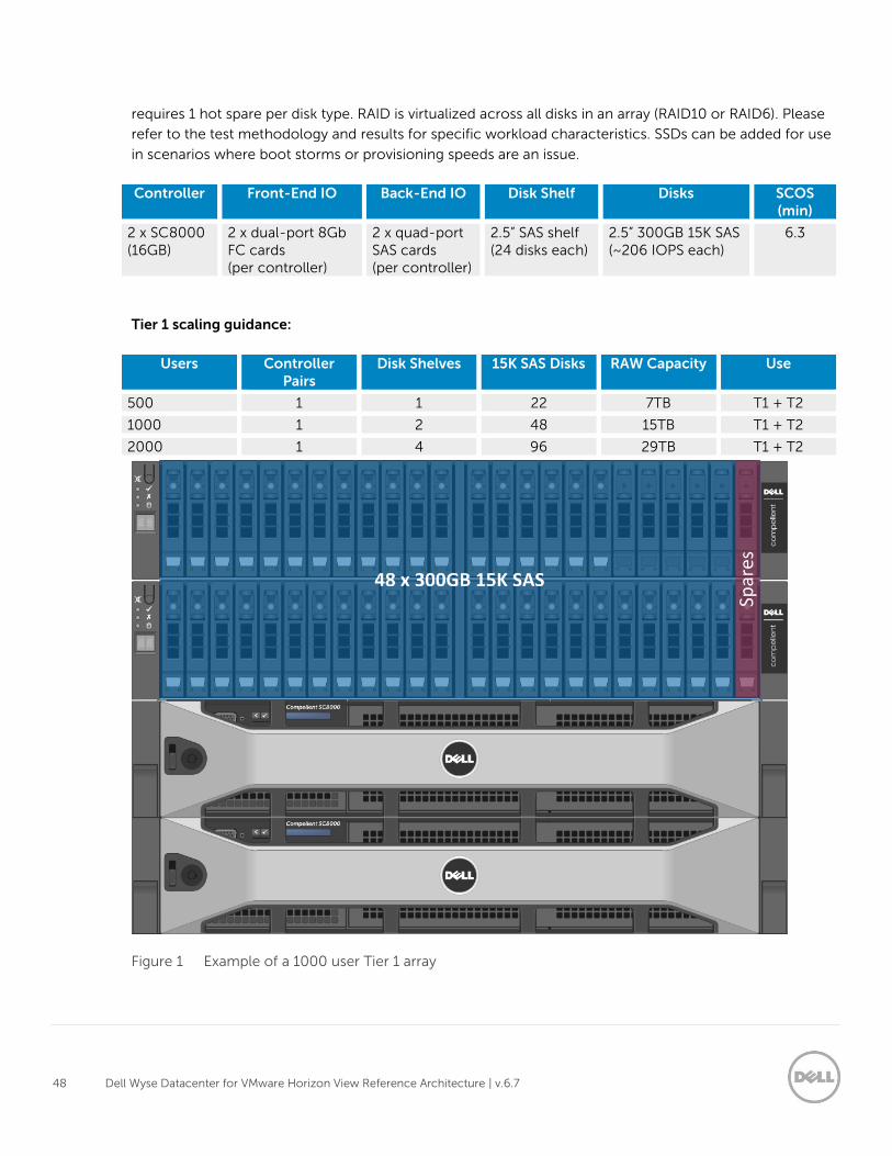
3.3.3.1 Compellent Tier 1 Compellent Tier 1 storage consists of a standard dual controller configuration and scales upward by
adding disks/shelves and additional discrete arrays. A single pair of SC8000 controllers will support Tier 1
and Tier 2 for 2000 knowledge worker users, as depicted below, utilizing all 15K SAS disks. If Tier 2 is to be
separated then an additional 30% of users can be added per Tier 1 array. Scaling above this number,
additional arrays will need to be implemented. Additional capacity and performance capability is achieved
by adding larger disks or shelves, as appropriate, up to the controller’s performance limits. Each disk shelf
48 Dell Wyse Datacenter for VMware Horizon View Reference Architecture | v.6.7
requires 1 hot spare per disk type. RAID is virtualized across all disks in an array (RAID10 or RAID6). Please
refer to the test methodology and results for specific workload characteristics. SSDs can be added for use
in scenarios where boot storms or provisioning speeds are an issue.
Controller Front-End IO Back-End IO Disk Shelf Disks SCOS (min)
2 x SC8000 (16GB)
2 x dual-port 8Gb FC cards (per controller)
2 x quad-port SAS cards (per controller)
2.5” SAS shelf (24 disks each)
2.5” 300GB 15K SAS (~206 IOPS each)
6.3
Tier 1 scaling guidance:
Users Controller Pairs
Disk Shelves 15K SAS Disks RAW Capacity Use
500 1 1 22 7TB T1 + T2
1000 1 2 48 15TB T1 + T2
2000 1 4 96 29TB T1 + T2
Figure 1 Example of a 1000 user Tier 1 array
49 Dell Wyse Datacenter for VMware Horizon View Reference Architecture | v.6.7
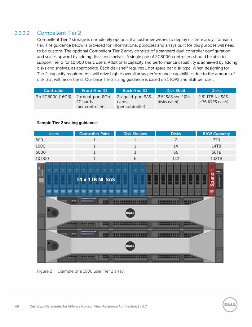
3.3.3.2 Compellent Tier 2 Compellent Tier 2 storage is completely optional if a customer wishes to deploy discrete arrays for each
tier. The guidance below is provided for informational purposes and arrays built for this purpose will need
to be custom. The optional Compellent Tier 2 array consists of a standard dual controller configuration
and scales upward by adding disks and shelves. A single pair of SC8000 controllers should be able to
support Tier 2 for 10,000 basic users. Additional capacity and performance capability is achieved by adding
disks and shelves, as appropriate. Each disk shelf requires 1 hot spare per disk type. When designing for
Tier 2, capacity requirements will drive higher overall array performance capabilities due to the amount of
disk that will be on hand. Our base Tier 2 sizing guidance is based on 1 IOPS and 5GB per user.
Controller Front-End IO Back-End IO Disk Shelf Disks
2 x SC8000 (16GB) 2 x dual-port 8Gb FC cards (per controller)
2 x quad-port SAS cards (per controller)
2.5” SAS shelf (24 disks each)
2.5” 1TB NL SAS (~76 IOPS each)
Sample Tier 2 scaling guidance:
Users Controller Pairs Disk Shelves Disks RAW Capacity
500 1 1 7 7TB
1000 1 1 14 14TB
5000 1 3 66 66TB
10,000 1 6 132 132TB
Figure 2 Example of a 1000 user Tier 2 array.
50 Dell Wyse Datacenter for VMware Horizon View Reference Architecture | v.6.7
3.3.4 NAS
3.3.4.1 FS7600
Model Features Scaling Uses
EqualLogic FS7600
Dual active-active controllers
24GB cache per controller (cache mirroring)
SMB & NFS support
AD-integration
Up to 2 FS7600 systems in a NAS cluster (4 controllers)
1Gb iSCSI via 16 x Ethernet ports
Each controller can support 1500 concurrent users
Up to 6000 total users in a 2 system NAS cluster
Scale out NAS for Local Tier 1 to provide file share HA
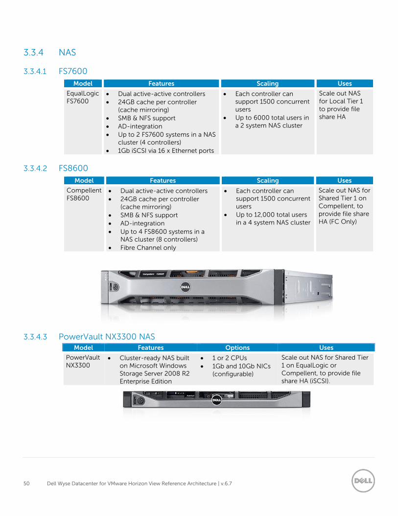
3.3.4.2 FS8600
Model Features Scaling Uses
Compellent FS8600
Dual active-active controllers
24GB cache per controller (cache mirroring)
SMB & NFS support
AD-integration
Up to 4 FS8600 systems in a NAS cluster (8 controllers)
Fibre Channel only
Each controller can support 1500 concurrent users
Up to 12,000 total users in a 4 system NAS cluster
Scale out NAS for Shared Tier 1 on Compellent, to provide file share HA (FC Only)
3.3.4.3 PowerVault NX3300 NAS Model Features Options Uses
PowerVault NX3300
Cluster-ready NAS built on Microsoft Windows Storage Server 2008 R2 Enterprise Edition
1 or 2 CPUs
1Gb and 10Gb NICs (configurable)
Scale out NAS for Shared Tier 1 on EqualLogic or Compellent, to provide file share HA (iSCSI).
51 Dell Wyse Datacenter for VMware Horizon View Reference Architecture | v.6.7
3.4 Wyse Cloud Clients The following Wyse Cloud Clients are the recommended choices for this solution.
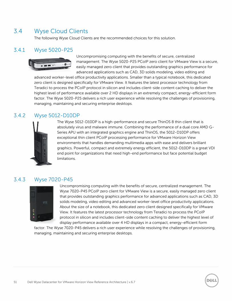
3.4.1 Wyse 5020-P25 Uncompromising computing with the benefits of secure, centralized
management. The Wyse 5020-P25 PCoIP zero client for VMware View is a secure,
easily managed zero client that provides outstanding graphics performance for
advanced applications such as CAD, 3D solids modeling, video editing and
advanced worker-level office productivity applications. Smaller than a typical notebook, this dedicated
zero client is designed specifically for VMware View. It features the latest processor technology from
Teradici to process the PCoIP protocol in silicon and includes client-side content caching to deliver the
highest level of performance available over 2 HD displays in an extremely compact, energy-efficient form
factor. The Wyse 5020-P25 delivers a rich user experience while resolving the challenges of provisioning,
managing, maintaining and securing enterprise desktops.
3.4.2 Wyse 5012-D10DP The Wyse 5012-D10DP is a high-performance and secure ThinOS 8 thin client that is
absolutely virus and malware immune. Combining the performance of a dual core AMD G-
Series APU with an integrated graphics engine and ThinOS, the 5012-D10DP offers
exceptional thin client PCoIP processing performance for VMware Horizon View
environments that handles demanding multimedia apps with ease and delivers brilliant
graphics. Powerful, compact and extremely energy efficient, the 5012-D10DP is a great VDI
end point for organizations that need high-end performance but face potential budget
limitations.
3.4.3 Wyse 7020-P45 Uncompromising computing with the benefits of secure, centralized management. The
Wyse 7020-P45 PCoIP zero client for VMware View is a secure, easily managed zero client
that provides outstanding graphics performance for advanced applications such as CAD, 3D
solids modeling, video editing and advanced worker-level office productivity applications.
About the size of a notebook, this dedicated zero client designed specifically for VMware
View. It features the latest processor technology from Teradici to process the PCoIP
protocol in silicon and includes client-side content caching to deliver the highest level of
display performance available over 4 HD displays in a compact, energy-efficient form
factor. The Wyse 7020-P45 delivers a rich user experience while resolving the challenges of provisioning,
managing, maintaining and securing enterprise desktops.
52 Dell Wyse Datacenter for VMware Horizon View Reference Architecture | v.6.7
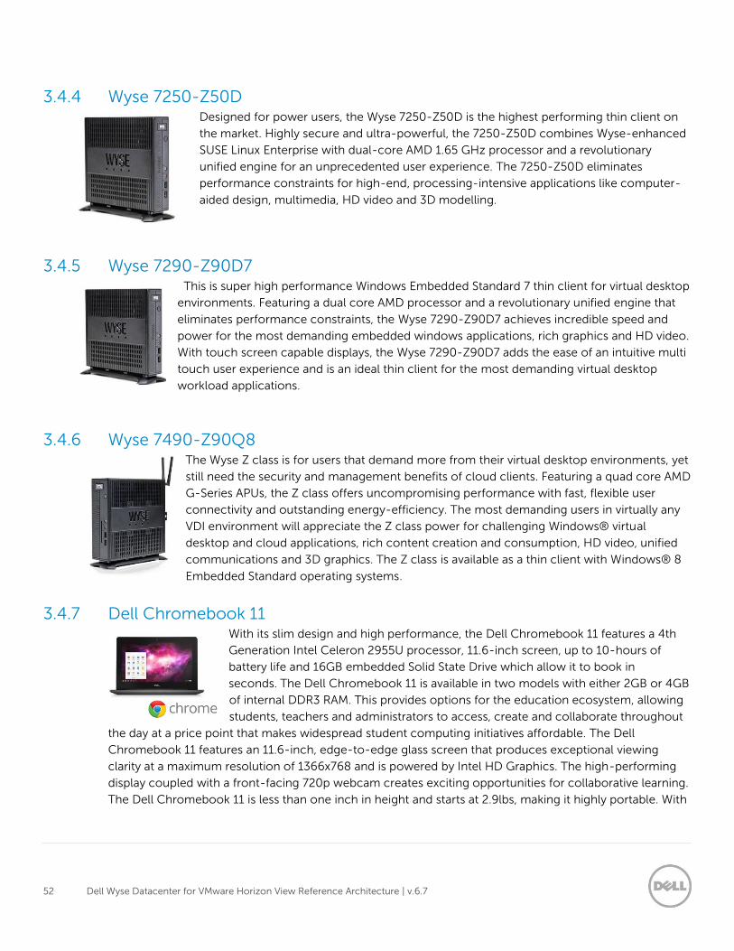
3.4.4 Wyse 7250-Z50D Designed for power users, the Wyse 7250-Z50D is the highest performing thin client on
the market. Highly secure and ultra-powerful, the 7250-Z50D combines Wyse-enhanced
SUSE Linux Enterprise with dual-core AMD 1.65 GHz processor and a revolutionary
unified engine for an unprecedented user experience. The 7250-Z50D eliminates
performance constraints for high-end, processing-intensive applications like computer-
aided design, multimedia, HD video and 3D modelling.
3.4.5 Wyse 7290-Z90D7 This is super high performance Windows Embedded Standard 7 thin client for virtual desktop
environments. Featuring a dual core AMD processor and a revolutionary unified engine that
eliminates performance constraints, the Wyse 7290-Z90D7 achieves incredible speed and
power for the most demanding embedded windows applications, rich graphics and HD video.
With touch screen capable displays, the Wyse 7290-Z90D7 adds the ease of an intuitive multi
touch user experience and is an ideal thin client for the most demanding virtual desktop
workload applications.
3.4.6 Wyse 7490-Z90Q8 The Wyse Z class is for users that demand more from their virtual desktop environments, yet
still need the security and management benefits of cloud clients. Featuring a quad core AMD
G-Series APUs, the Z class offers uncompromising performance with fast, flexible user
connectivity and outstanding energy-efficiency. The most demanding users in virtually any
VDI environment will appreciate the Z class power for challenging Windows® virtual
desktop and cloud applications, rich content creation and consumption, HD video, unified
communications and 3D graphics. The Z class is available as a thin client with Windows® 8
Embedded Standard operating systems.
3.4.7 Dell Chromebook 11 With its slim design and high performance, the Dell Chromebook 11 features a 4th
Generation Intel Celeron 2955U processor, 11.6-inch screen, up to 10-hours of
battery life and 16GB embedded Solid State Drive which allow it to book in
seconds. The Dell Chromebook 11 is available in two models with either 2GB or 4GB
of internal DDR3 RAM. This provides options for the education ecosystem, allowing
students, teachers and administrators to access, create and collaborate throughout
the day at a price point that makes widespread student computing initiatives affordable. The Dell
Chromebook 11 features an 11.6-inch, edge-to-edge glass screen that produces exceptional viewing
clarity at a maximum resolution of 1366x768 and is powered by Intel HD Graphics. The high-performing
display coupled with a front-facing 720p webcam creates exciting opportunities for collaborative learning.
The Dell Chromebook 11 is less than one inch in height and starts at 2.9lbs, making it highly portable. With
53 Dell Wyse Datacenter for VMware Horizon View Reference Architecture | v.6.7
two USB 3.0 ports, Bluetooth 4.0 and an HDMI port, end users have endless possibilities for collaborating,
creating, consuming and displaying content. With battery life of up to 10-hours, the Chromebook is
capable of powering end users throughout the day.
Finally with a fully compliant HTML5 browser, the Dell Chromebook11 is an excellent choice as an
endpoint to a HTML5/BLAST connect Horizon View VDI desktop.
54 Dell Wyse Datacenter for VMware Horizon View Reference Architecture | v.6.7
4 Software components
4.1 What's new in this release of Horizon View 6.0? This new release of VMware Horizon View delivers following important new features and enhancements:
RemoteApp – RemoteApp enables administrators to make programs that are accessed remotely through
a Remote Desktop Session (RDS) server appear as if they are running on the client computer versus a
remote desktop.
Virtual SAN – Horizon 6 with VMware Virtual SAN™ is a new storage technology that automates storage
provisioning and pools together with server-attached flash drives and hard disks and virtualizes them into
reliable storage. Built into the vSphere platform, the technology offers greater performance while
simplifying storage management. Virtual SAN eliminates the need to overprovision storage to ensure that
end users have enough IOPS per desktop.
Cloud pod architecture – The cloud pod architecture allows organizations to dynamically move and
locate View pods across multiple data centers for efficient management of end users across distributed
locations.
vDGA and vSGA 3D graphics enhancements – 3D graphics capabilities are enhanced to augment a
graphically rich user experience. Using Virtual Dedicated Graphics Acceleration (vDGA), a single virtual
machine is mapped to one physical graphics processing unit (GPU) in the ESXi host, providing high-end,
hardware-accelerated workstation graphics. Using Virtual Shared Graphics Acceleration (vSGA), multiple
virtual machines leverage physical GPUs that are installed locally in ESXi hosts, providing hardware
accelerated 3D graphics to multiple virtual desktops.
Unity Touch enhancements – Enhancements to VMware Unity Touch technology make it easier to
connect to View Connection Server or a View security server, log in to remote desktops in the data center,
and edit the list of connected servers. Unity Touch for VMware Horizon Client makes it easier to run
Windows apps on iPhone, iPad, and Android devices.
Additional OS support – View Connection Server, security server, and View Composer are supported on
Windows Server 2012 R2 operating systems.
Horizon View logs – Ability to send Horizon View logs to a Syslog server such as VMware vCenter Log
Insight.
Horizon View Agent – The Remote Experience Agent is now integrated with View Agent. Previously, you
had to install View Agent and the Remote Experience Agent to use features such as HTML Access, Unity
Touch, Real-Time Audio-Video, and Windows 7 Multimedia Redirection. In this release these features are
available by installing just the View Agent.
55 Dell Wyse Datacenter for VMware Horizon View Reference Architecture | v.6.7
4.2 VMware Horizon View The solution is based on VMware Horizon View which provides a complete end-to-end solution delivering
Microsoft Windows virtual desktops to users on a wide variety of endpoint devices. Virtual desktops are
dynamically assembled on demand, providing users with pristine, yet personalized, desktops each time
they log on.
VMware Horizon View provides a complete virtual desktop delivery system by integrating several
distributed components with advanced configuration tools that simplify the creation and real-time
management of the virtual desktop infrastructure. For the complete set of details, please see the Horizon
View resources page at http://www.vmware.com/products/horizon-view/resources.html
The core Horizon View components include:
View Connection Server (VCS) – Installed on servers in the data center and brokers client connections,
The VCS authenticates users, entitles users by mapping them to desktops and/or pools, establishes secure
connections from clients to desktops, support single sign-on, sets and applies policies, acts as a DMZ
security server for outside corporate firewall connections and more.
View Client – Installed on endpoints. Is software for creating connections to View desktops that can be
run from tablets, Windows, Linux, or Mac PCs or laptops, thin clients and other devices.
View Portal – A web portal to access links for downloading full View clients. With HTML Access Feature
enabled enablement for running a View desktop inside a supported browser is enabled.
View Agent – Installed on all VMs, physical machines and Terminal Service servers that are used as a
source for View desktops. On VMs the agent is used to communicate with the View client to provide
services such as USB redirection, printer support and more.
View Administrator – A web portal that provides admin functions such as deploy and management of
View desktops and pools, set and control user authentication and more.
View Composer – This software service can be installed standalone or on the vCenter server and provides
enablement to deploy and create linked clone desktop pools (also called non-persistent desktops).
vCenter Server – This is a server that provides centralized management and configuration to entire virtual
desktop and host infrastructure. It facilitates configuration, provision, management services. It is installed
on a Windows Server 2008 host (can be a VM).
View Transfer Server – Manages data transfers between the data center and the View desktops that are
checked out on the end users’ desktops in offline mode. This Server is required to support desktops that
run the View client with Local Mode options. Replications and syncing are the functions it will perform
with offline images.
56 Dell Wyse Datacenter for VMware Horizon View Reference Architecture | v.6.7
4.3 VDI hypervisor platform
4.3.1 VMware vSphere 5 VMware vSphere 5 (currently vSphere 5.5 U2) is a virtualization platform used for building VDI and cloud
infrastructures. vSphere 5 represents a migration from the ESX architecture to the ESXi architecture.
VMware vSphere 5 includes three major layers: Virtualization, Management and Interface. The
Virtualization layer includes infrastructure and application services. The Management layer is central for
configuring, provisioning and managing virtualized environments. The Interface layer includes the vSphere
client and the vSphere web client.
Throughout the Dell Wyse Datacenter solution, all VMware best practices and prerequisites are adhered to
(NTP, DNS, Active Directory, etc.). The vCenter 5 VM used in the solution will be a single Windows Server
2012 R2 VM (Check for current Windows Server OS compatibility at:
http://www.vmware.com/resources/compatibility ), residing on a host in the management tier. SQL server
is a core component of vCenter and will be hosted on another VM also residing in the management tier.
All additional Horizon View components need to be installed in a distributed architecture, 1 role per VM.
For more information on VMware vSphere, visit http://www.vmware.com/products/vsphere
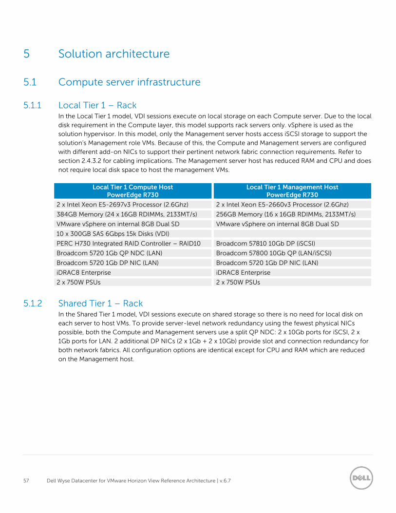
57 Dell Wyse Datacenter for VMware Horizon View Reference Architecture | v.6.7
5 Solution architecture
5.1 Compute server infrastructure
5.1.1 Local Tier 1 – Rack In the Local Tier 1 model, VDI sessions execute on local storage on each Compute server. Due to the local
disk requirement in the Compute layer, this model supports rack servers only. vSphere is used as the
solution hypervisor. In this model, only the Management server hosts access iSCSI storage to support the
solution’s Management role VMs. Because of this, the Compute and Management servers are configured
with different add-on NICs to support their pertinent network fabric connection requirements. Refer to
section 2.4.3.2 for cabling implications. The Management server host has reduced RAM and CPU and does
not require local disk space to host the management VMs.
Local Tier 1 Compute Host PowerEdge R730
Local Tier 1 Management Host PowerEdge R730
2 x Intel Xeon E5-2697v3 Processor (2.6Ghz) 2 x Intel Xeon E5-2660v3 Processor (2.6Ghz)
384GB Memory (24 x 16GB RDIMMs, 2133MT/s) 256GB Memory (16 x 16GB RDIMMs, 2133MT/s)
VMware vSphere on internal 8GB Dual SD VMware vSphere on internal 8GB Dual SD
10 x 300GB SAS 6Gbps 15k Disks (VDI)
PERC H730 Integrated RAID Controller – RAID10 Broadcom 57810 10Gb DP (iSCSI)
Broadcom 5720 1Gb QP NDC (LAN) Broadcom 57800 10Gb QP (LAN/iSCSI)
Broadcom 5720 1Gb DP NIC (LAN) Broadcom 5720 1Gb DP NIC (LAN)
iDRAC8 Enterprise iDRAC8 Enterprise
2 x 750W PSUs 2 x 750W PSUs
5.1.2 Shared Tier 1 – Rack In the Shared Tier 1 model, VDI sessions execute on shared storage so there is no need for local disk on
each server to host VMs. To provide server-level network redundancy using the fewest physical NICs
possible, both the Compute and Management servers use a split QP NDC: 2 x 10Gb ports for iSCSI, 2 x
1Gb ports for LAN. 2 additional DP NICs (2 x 1Gb + 2 x 10Gb) provide slot and connection redundancy for
both network fabrics. All configuration options are identical except for CPU and RAM which are reduced
on the Management host.
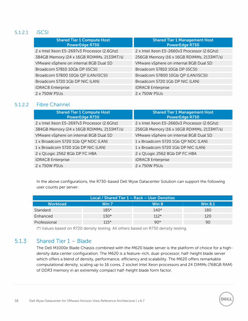
58 Dell Wyse Datacenter for VMware Horizon View Reference Architecture | v.6.7
5.1.2.1 iSCSI
Shared Tier 1 Compute Host PowerEdge R730
Shared Tier 1 Management Host PowerEdge R730
2 x Intel Xeon E5-2697v3 Processor (2.6Ghz) 2 x Intel Xeon E5-2660v3 Processor (2.6Ghz)
384GB Memory (24 x 16GB RDIMMs, 2133MT/s) 256GB Memory (16 x 16GB RDIMMs, 2133MT/s)
VMware vSphere on internal 8GB Dual SD VMware vSphere on internal 8GB Dual SD
Broadcom 57810 10Gb DP (iSCSI) Broadcom 57810 10Gb DP (iSCSI)
Broadcom 57800 10Gb QP (LAN/iSCSI) Broadcom 57800 10Gb QP (LAN/iSCSI)
Broadcom 5720 1Gb DP NIC (LAN) Broadcom 5720 1Gb DP NIC (LAN)
iDRAC8 Enterprise iDRAC8 Enterprise
2 x 750W PSUs 2 x 750W PSUs
5.1.2.2 Fibre Channel
Shared Tier 1 Compute Host PowerEdge R730
Shared Tier 1 Management Host PowerEdge R730
2 x Intel Xeon E5-2697v3 Processor (2.6Ghz) 2 x Intel Xeon E5-2660v3 Processor (2.6Ghz)
384GB Memory (24 x 16GB RDIMMs, 2133MT/s) 256GB Memory (16 x 16GB RDIMMs, 2133MT/s)
VMware vSphere on internal 8GB Dual SD VMware vSphere on internal 8GB Dual SD
1 x Broadcom 5720 1Gb QP NDC (LAN) 1 x Broadcom 5720 1Gb QP NDC (LAN)
1 x Broadcom 5720 1Gb DP NIC (LAN) 1 x Broadcom 5720 1Gb DP NIC (LAN)
2 x QLogic 2562 8Gb DP FC HBA 2 x QLogic 2562 8Gb DP FC HBA
iDRAC8 Enterprise iDRAC8 Enterprise
2 x 750W PSUs 2 x 750W PSUs
In the above configurations, the R730-based Dell Wyse Datacenter Solution can support the following
user counts per server:
Local / Shared Tier 1 – Rack – User Densities
Workload Win 7 Win 8 Win 8.1
Standard 185* 140* 180
Enhanced 130* 112* 120
Professional 115* 90* 90
(*) Values based on R720 density testing. All others based on R730 density testing.
5.1.3 Shared Tier 1 – Blade The Dell M1000e Blade Chassis combined with the M620 blade server is the platform of choice for a high-
density data center configuration. The M620 is a feature-rich, dual-processor, half-height blade server
which offers a blend of density, performance, efficiency and scalability. The M620 offers remarkable
computational density, scaling up to 16 cores, 2 socket Intel Xeon processors and 24 DIMMs (768GB RAM)
of DDR3 memory in an extremely compact half-height blade form factor.
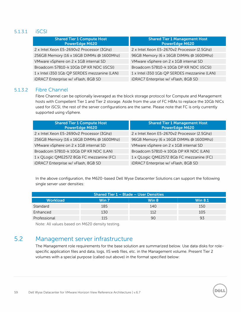
59 Dell Wyse Datacenter for VMware Horizon View Reference Architecture | v.6.7
5.1.3.1 iSCSI
Shared Tier 1 Compute Host PowerEdge M620
Shared Tier 1 Management Host PowerEdge M620
2 x Intel Xeon E5-2690v2 Processor (3Ghz) 2 x Intel Xeon E5-2670v2 Processor (2.5Ghz)
256GB Memory (16 x 16GB DIMMs @ 1600Mhz) 96GB Memory (6 x 16GB DIMMs @ 1600Mhz)
VMware vSphere on 2 x 1GB internal SD VMware vSphere on 2 x 1GB internal SD
Broadcom 57810-k 10Gb DP KR NDC (iSCSI) Broadcom 57810-k 10Gb DP KR NDC (iSCSI)
1 x Intel i350 1Gb QP SERDES mezzanine (LAN) 1 x Intel i350 1Gb QP SERDES mezzanine (LAN)
iDRAC7 Enterprise w/ vFlash, 8GB SD iDRAC7 Enterprise w/ vFlash, 8GB SD
5.1.3.2 Fibre Channel Fibre Channel can be optionally leveraged as the block storage protocol for Compute and Management
hosts with Compellent Tier 1 and Tier 2 storage. Aside from the use of FC HBAs to replace the 10Gb NICs
used for iSCSI, the rest of the server configurations are the same. Please note that FC is only currently
supported using vSphere.
Shared Tier 1 Compute Host PowerEdge M620
Shared Tier 1 Management Host PowerEdge M620
2 x Intel Xeon E5-2690v2 Processor (3Ghz) 2 x Intel Xeon E5-2670v2 Processor (2.5Ghz)
256GB Memory (16 x 16GB DIMMs @ 1600Mhz) 96GB Memory (6 x 16GB DIMMs @ 1600Mhz)
VMware vSphere on 2 x 1GB internal SD VMware vSphere on 2 x 1GB internal SD
Broadcom 57810-k 10Gb DP KR NDC (LAN) Broadcom 57810-k 10Gb DP KR NDC (LAN)
1 x QLogic QME2572 8Gb FC mezzanine (FC) 1 x QLogic QME2572 8Gb FC mezzanine (FC)
iDRAC7 Enterprise w/ vFlash, 8GB SD iDRAC7 Enterprise w/ vFlash, 8GB SD
In the above configuration, the M620-based Dell Wyse Datacenter Solutions can support the following
single server user densities:
Shared Tier 1 – Blade – User Densities
Workload Win 7 Win 8 Win 8.1
Standard 185 140 150
Enhanced 130 112 105
Professional 115 90 93
Note: All values based on M620 density testing.
5.2 Management server infrastructure The Management role requirements for the base solution are summarized below. Use data disks for role-
specific application files and data, logs, IIS web files, etc. in the Management volume. Present Tier 2
volumes with a special purpose (called out above) in the format specified below:
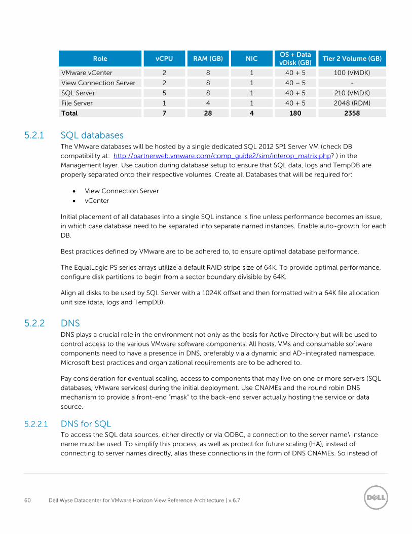
60 Dell Wyse Datacenter for VMware Horizon View Reference Architecture | v.6.7
Role vCPU RAM (GB) NIC OS + Data vDisk (GB)
Tier 2 Volume (GB)
VMware vCenter 2 8 1 40 + 5 100 (VMDK)
View Connection Server 2 8 1 40 – 5 -
SQL Server 5 8 1 40 + 5 210 (VMDK)
File Server 1 4 1 40 + 5 2048 (RDM)
Total 7 28 4 180 2358
5.2.1 SQL databases The VMware databases will be hosted by a single dedicated SQL 2012 SP1 Server VM (check DB
compatibility at: http://partnerweb.vmware.com/comp_guide2/sim/interop_matrix.php? ) in the
Management layer. Use caution during database setup to ensure that SQL data, logs and TempDB are
properly separated onto their respective volumes. Create all Databases that will be required for:
View Connection Server
vCenter
Initial placement of all databases into a single SQL instance is fine unless performance becomes an issue,
in which case database need to be separated into separate named instances. Enable auto-growth for each
DB.
Best practices defined by VMware are to be adhered to, to ensure optimal database performance.
The EqualLogic PS series arrays utilize a default RAID stripe size of 64K. To provide optimal performance,
configure disk partitions to begin from a sector boundary divisible by 64K.
Align all disks to be used by SQL Server with a 1024K offset and then formatted with a 64K file allocation
unit size (data, logs and TempDB).
5.2.2 DNS DNS plays a crucial role in the environment not only as the basis for Active Directory but will be used to
control access to the various VMware software components. All hosts, VMs and consumable software
components need to have a presence in DNS, preferably via a dynamic and AD-integrated namespace.
Microsoft best practices and organizational requirements are to be adhered to.
Pay consideration for eventual scaling, access to components that may live on one or more servers (SQL
databases, VMware services) during the initial deployment. Use CNAMEs and the round robin DNS
mechanism to provide a front-end “mask” to the back-end server actually hosting the service or data
source.
5.2.2.1 DNS for SQL To access the SQL data sources, either directly or via ODBC, a connection to the server name\ instance
name must be used. To simplify this process, as well as protect for future scaling (HA), instead of
connecting to server names directly, alias these connections in the form of DNS CNAMEs. So instead of
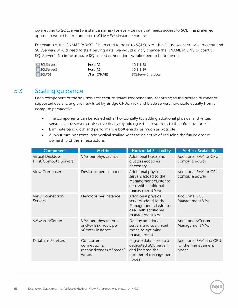
61 Dell Wyse Datacenter for VMware Horizon View Reference Architecture | v.6.7
connecting to SQLServer1\<instance name> for every device that needs access to SQL, the preferred
approach would be to connect to <CNAME>\<instance name>.
For example, the CNAME “VDISQL” is created to point to SQLServer1. If a failure scenario was to occur and
SQLServer2 would need to start serving data, we would simply change the CNAME in DNS to point to
SQLServer2. No infrastructure SQL client connections would need to be touched.
5.3 Scaling guidance Each component of the solution architecture scales independently according to the desired number of
supported users. Using the new Intel Ivy Bridge CPUs, rack and blade servers now scale equally from a
compute perspective.
The components can be scaled either horizontally (by adding additional physical and virtual
servers to the server pools) or vertically (by adding virtual resources to the infrastructure)
Eliminate bandwidth and performance bottlenecks as much as possible
Allow future horizontal and vertical scaling with the objective of reducing the future cost of
ownership of the infrastructure.
Component Metric Horizontal Scalability Vertical Scalability
Virtual Desktop Host/Compute Servers
VMs per physical host Additional hosts and clusters added as necessary
Additional RAM or CPU compute power
View Composer Desktops per instance Additional physical servers added to the Management cluster to deal with additional management VMs.
Additional RAM or CPU compute power
View Connection Servers
Desktops per instance Additional physical servers added to the Management cluster to deal with additional management VMs.
Additional VCS Management VMs.
VMware vCenter VMs per physical host and/or ESX hosts per vCenter instance
Deploy additional servers and use linked mode to optimize management
Additional vCenter Management VMs.
Database Services Concurrent connections, responsiveness of reads/ writes
Migrate databases to a dedicated SQL server and increase the number of management nodes
Additional RAM and CPU for the management nodes
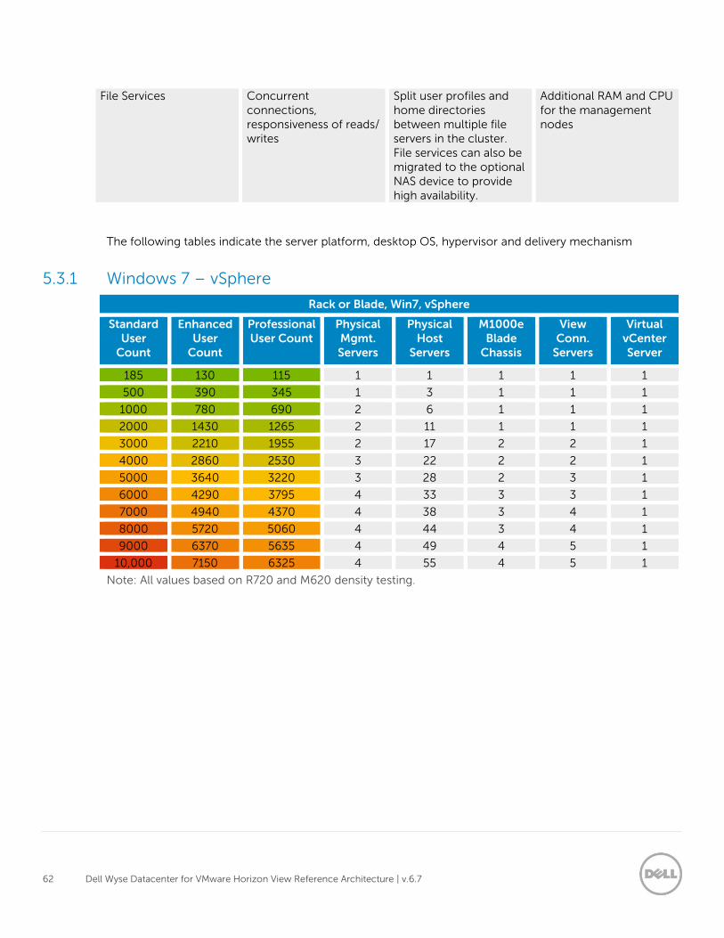
62 Dell Wyse Datacenter for VMware Horizon View Reference Architecture | v.6.7
File Services Concurrent connections, responsiveness of reads/ writes
Split user profiles and home directories between multiple file servers in the cluster. File services can also be migrated to the optional NAS device to provide high availability.
Additional RAM and CPU for the management nodes
The following tables indicate the server platform, desktop OS, hypervisor and delivery mechanism
5.3.1 Windows 7 – vSphere
Rack or Blade, Win7, vSphere
Standard User
Count
Enhanced User
Count
Professional User Count
Physical Mgmt. Servers
Physical Host
Servers
M1000e Blade
Chassis
View Conn.
Servers
Virtual vCenter Server
185 130 115 1 1 1 1 1
500 390 345 1 3 1 1 1
1000 780 690 2 6 1 1 1
2000 1430 1265 2 11 1 1 1
3000 2210 1955 2 17 2 2 1
4000 2860 2530 3 22 2 2 1
5000 3640 3220 3 28 2 3 1
6000 4290 3795 4 33 3 3 1
7000 4940 4370 4 38 3 4 1
8000 5720 5060 4 44 3 4 1
9000 6370 5635 4 49 4 5 1
10,000 7150 6325 4 55 4 5 1
Note: All values based on R720 and M620 density testing.
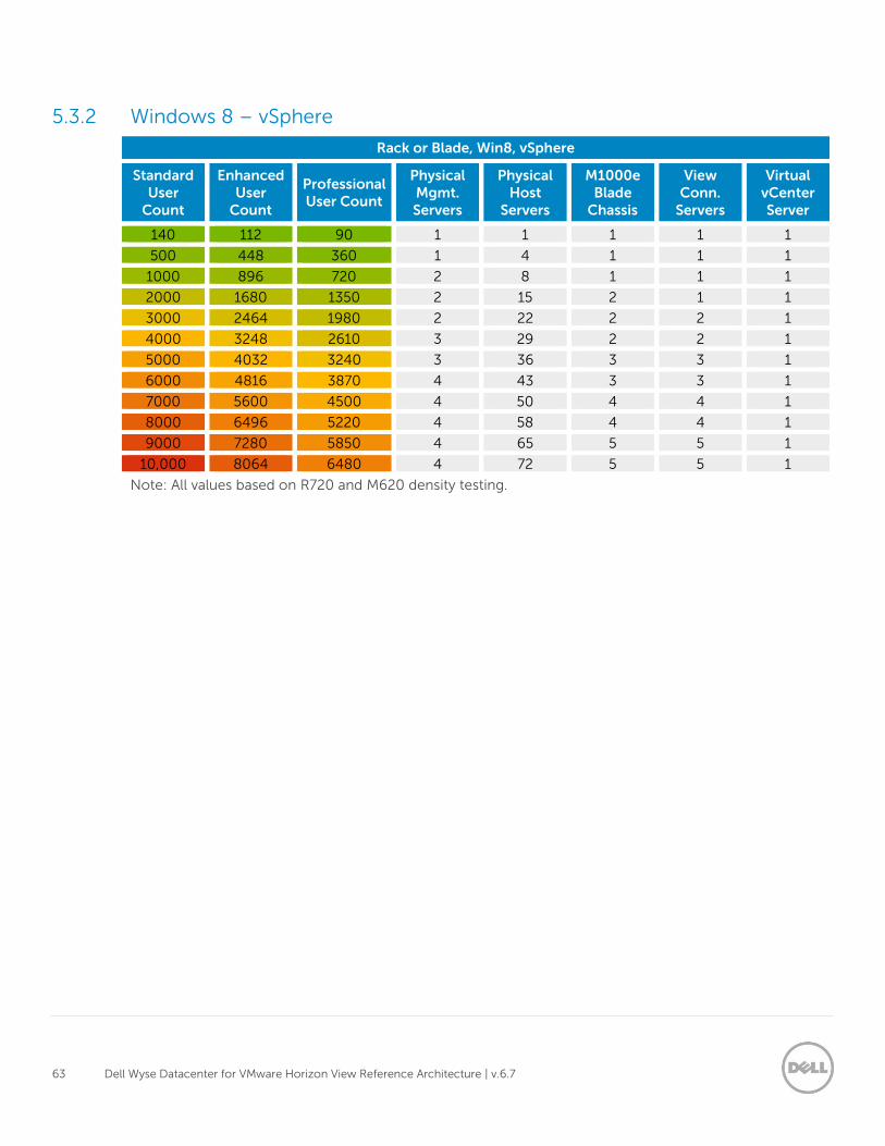
63 Dell Wyse Datacenter for VMware Horizon View Reference Architecture | v.6.7
5.3.2 Windows 8 – vSphere
Rack or Blade, Win8, vSphere
Standard User
Count
Enhanced User
Count
Professional User Count
Physical Mgmt. Servers
Physical Host
Servers
M1000e Blade
Chassis
View Conn.
Servers
Virtual vCenter Server
140 112 90 1 1 1 1 1
500 448 360 1 4 1 1 1
1000 896 720 2 8 1 1 1
2000 1680 1350 2 15 2 1 1
3000 2464 1980 2 22 2 2 1
4000 3248 2610 3 29 2 2 1
5000 4032 3240 3 36 3 3 1
6000 4816 3870 4 43 3 3 1
7000 5600 4500 4 50 4 4 1
8000 6496 5220 4 58 4 4 1
9000 7280 5850 4 65 5 5 1
10,000 8064 6480 4 72 5 5 1
Note: All values based on R720 and M620 density testing.
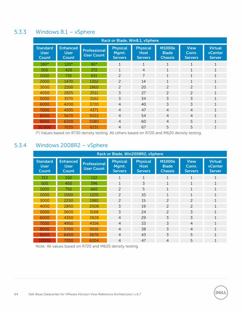
64 Dell Wyse Datacenter for VMware Horizon View Reference Architecture | v.6.7
5.3.3 Windows 8.1 – vSphere
Rack or Blade, Win8.1, vSphere
Standard User
Count
Enhanced User
Count
Professional User Count
Physical Mgmt. Servers
Physical Host
Servers
M1000e Blade
Chassis
View Conn.
Servers
Virtual vCenter Server
180* 120* 90* 1 1 1 1 1
500 420 372 1 4 1 1 1
1000 735 651 2 7 1 1 1
2000 1470 1302 2 14 1 1 1
3000 2100 1860 2 20 2 2 1
4000 2835 2511 3 27 2 2 1
5000 3570 3162 3 34 3 3 1
6000 4200 3720 4 40 3 3 1
7000 4935 4371 4 47 4 4 1
8000 5670 5022 4 54 4 4 1
9000 6300 5580 4 60 4 5 1
10,000 7035 6231 4 67 5 5 1
(*) Values based on R730 density testing. All others based on R720 and M620 density testing.
5.3.4 Windows 2008R2 – vSphere
Rack or Blade, Win2008R2, vSphere
Standard User
Count
Enhanced User
Count
Professional User Count
Physical Mgmt. Servers
Physical Host
Servers
M1000e Blade
Chassis
View Conn.
Servers
Virtual vCenter Server
213 150 132 1 1 1 1 1
500 450 396 1 3 1 1 1
1000 750 660 2 5 1 1 1
2000 1500 1320 2 10 1 1 1
3000 2250 1980 2 15 2 2 1
4000 2850 2508 3 19 2 2 1
5000 3600 3168 3 24 2 3 1
6000 4350 3828 4 29 3 3 1
7000 4950 4356 4 33 3 4 1
8000 5700 5016 4 38 3 4 1
9000 6450 5676 4 43 3 5 1
10000 7050 6204 4 47 4 5 1
Note: All values based on R720 and M620 density testing.
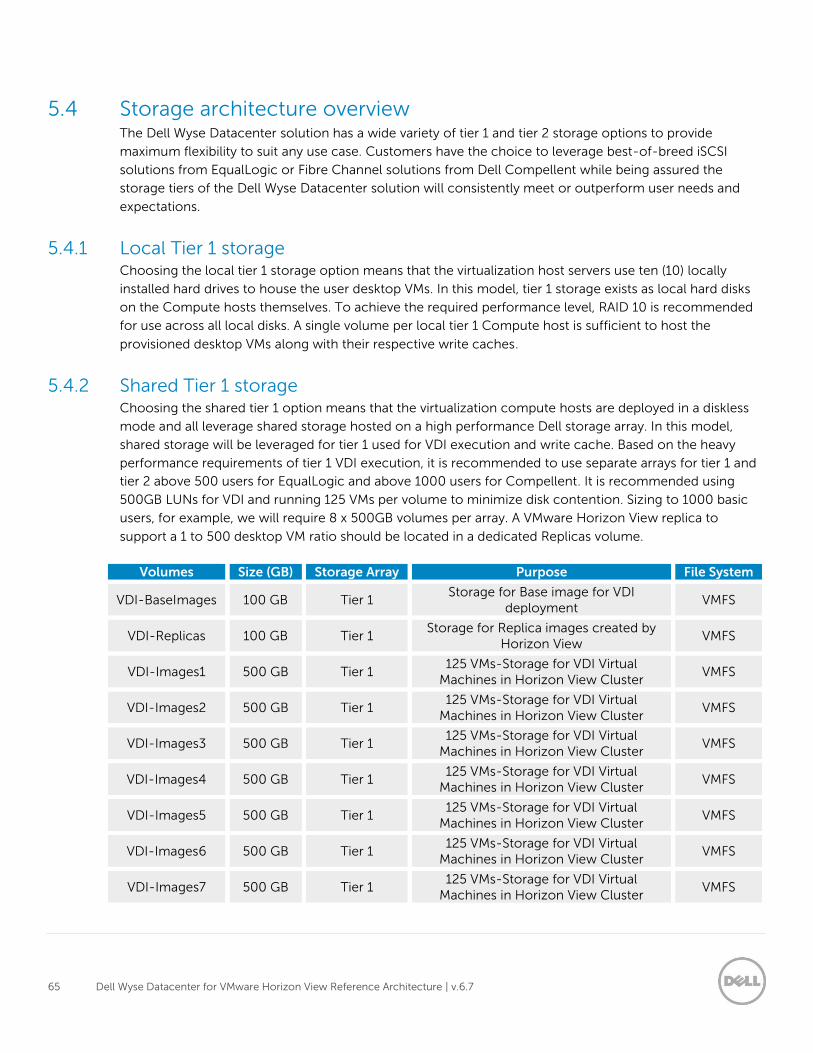
65 Dell Wyse Datacenter for VMware Horizon View Reference Architecture | v.6.7
5.4 Storage architecture overview The Dell Wyse Datacenter solution has a wide variety of tier 1 and tier 2 storage options to provide
maximum flexibility to suit any use case. Customers have the choice to leverage best-of-breed iSCSI
solutions from EqualLogic or Fibre Channel solutions from Dell Compellent while being assured the
storage tiers of the Dell Wyse Datacenter solution will consistently meet or outperform user needs and
expectations.
5.4.1 Local Tier 1 storage Choosing the local tier 1 storage option means that the virtualization host servers use ten (10) locally
installed hard drives to house the user desktop VMs. In this model, tier 1 storage exists as local hard disks
on the Compute hosts themselves. To achieve the required performance level, RAID 10 is recommended
for use across all local disks. A single volume per local tier 1 Compute host is sufficient to host the
provisioned desktop VMs along with their respective write caches.
5.4.2 Shared Tier 1 storage Choosing the shared tier 1 option means that the virtualization compute hosts are deployed in a diskless
mode and all leverage shared storage hosted on a high performance Dell storage array. In this model,
shared storage will be leveraged for tier 1 used for VDI execution and write cache. Based on the heavy
performance requirements of tier 1 VDI execution, it is recommended to use separate arrays for tier 1 and
tier 2 above 500 users for EqualLogic and above 1000 users for Compellent. It is recommended using
500GB LUNs for VDI and running 125 VMs per volume to minimize disk contention. Sizing to 1000 basic
users, for example, we will require 8 x 500GB volumes per array. A VMware Horizon View replica to
support a 1 to 500 desktop VM ratio should be located in a dedicated Replicas volume.
Volumes Size (GB) Storage Array Purpose File System
VDI-BaseImages 100 GB Tier 1 Storage for Base image for VDI
deployment VMFS
VDI-Replicas 100 GB Tier 1 Storage for Replica images created by
Horizon View VMFS
VDI-Images1 500 GB Tier 1 125 VMs-Storage for VDI Virtual
Machines in Horizon View Cluster VMFS
VDI-Images2 500 GB Tier 1 125 VMs-Storage for VDI Virtual
Machines in Horizon View Cluster VMFS
VDI-Images3 500 GB Tier 1 125 VMs-Storage for VDI Virtual
Machines in Horizon View Cluster VMFS
VDI-Images4 500 GB Tier 1 125 VMs-Storage for VDI Virtual
Machines in Horizon View Cluster VMFS
VDI-Images5 500 GB Tier 1 125 VMs-Storage for VDI Virtual
Machines in Horizon View Cluster VMFS
VDI-Images6 500 GB Tier 1 125 VMs-Storage for VDI Virtual
Machines in Horizon View Cluster VMFS
VDI-Images7 500 GB Tier 1 125 VMs-Storage for VDI Virtual
Machines in Horizon View Cluster VMFS
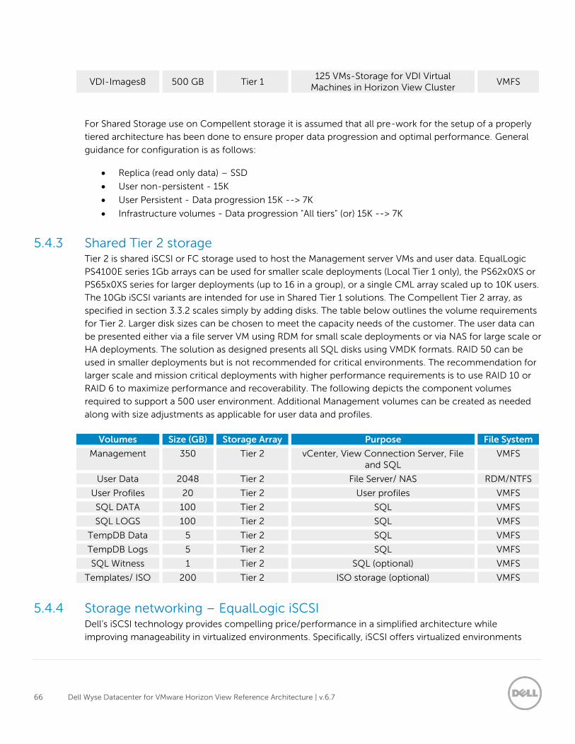
66 Dell Wyse Datacenter for VMware Horizon View Reference Architecture | v.6.7
VDI-Images8 500 GB Tier 1 125 VMs-Storage for VDI Virtual
Machines in Horizon View Cluster VMFS
For Shared Storage use on Compellent storage it is assumed that all pre-work for the setup of a properly
tiered architecture has been done to ensure proper data progression and optimal performance. General
guidance for configuration is as follows:
Replica (read only data) – SSD
User non-persistent - 15K
User Persistent - Data progression 15K --> 7K
Infrastructure volumes - Data progression "All tiers" (or) 15K --> 7K
5.4.3 Shared Tier 2 storage Tier 2 is shared iSCSI or FC storage used to host the Management server VMs and user data. EqualLogic
PS4100E series 1Gb arrays can be used for smaller scale deployments (Local Tier 1 only), the PS62x0XS or
PS65x0XS series for larger deployments (up to 16 in a group), or a single CML array scaled up to 10K users.
The 10Gb iSCSI variants are intended for use in Shared Tier 1 solutions. The Compellent Tier 2 array, as
specified in section 3.3.2 scales simply by adding disks. The table below outlines the volume requirements
for Tier 2. Larger disk sizes can be chosen to meet the capacity needs of the customer. The user data can
be presented either via a file server VM using RDM for small scale deployments or via NAS for large scale or
HA deployments. The solution as designed presents all SQL disks using VMDK formats. RAID 50 can be
used in smaller deployments but is not recommended for critical environments. The recommendation for
larger scale and mission critical deployments with higher performance requirements is to use RAID 10 or
RAID 6 to maximize performance and recoverability. The following depicts the component volumes
required to support a 500 user environment. Additional Management volumes can be created as needed
along with size adjustments as applicable for user data and profiles.
Volumes Size (GB) Storage Array Purpose File System
Management 350 Tier 2 vCenter, View Connection Server, File and SQL
VMFS
User Data 2048 Tier 2 File Server/ NAS RDM/NTFS
User Profiles 20 Tier 2 User profiles VMFS
SQL DATA 100 Tier 2 SQL VMFS
SQL LOGS 100 Tier 2 SQL VMFS
TempDB Data 5 Tier 2 SQL VMFS
TempDB Logs 5 Tier 2 SQL VMFS
SQL Witness 1 Tier 2 SQL (optional) VMFS
Templates/ ISO 200 Tier 2 ISO storage (optional) VMFS
5.4.4 Storage networking – EqualLogic iSCSI Dell’s iSCSI technology provides compelling price/performance in a simplified architecture while
improving manageability in virtualized environments. Specifically, iSCSI offers virtualized environments
67 Dell Wyse Datacenter for VMware Horizon View Reference Architecture | v.6.7
simplified deployment, comprehensive storage management and data protection functionality and
seamless VM mobility. Dell iSCSI solutions give customers the “Storage Direct” advantage – the ability to
seamlessly integrate virtualization into an overall, optimized storage environment.
If iSCSI is the selected block storage protocol, then the Dell EqualLogic MPIO plugin is installed on all
hosts that connect to iSCSI storage. This module is added via a command line using a Virtual Management
Appliance (vMA) from VMware. This plugin allows for easy configuration of iSCSI on each host. The MPIO
plugin allows the creation of new or access to existing data stores and handle IO load balancing. The
plugin will also configure the optimal multi-path settings for the data stores as well. Some key settings to
be used as part of the configuration:
Specify 2 IP Addresses for iSCSI on each host
Specify NICs
Specify Jumbo Frames at 9000 MTU
Initialize iSCSI initiator
Specify IP for the EqualLogic Storage group
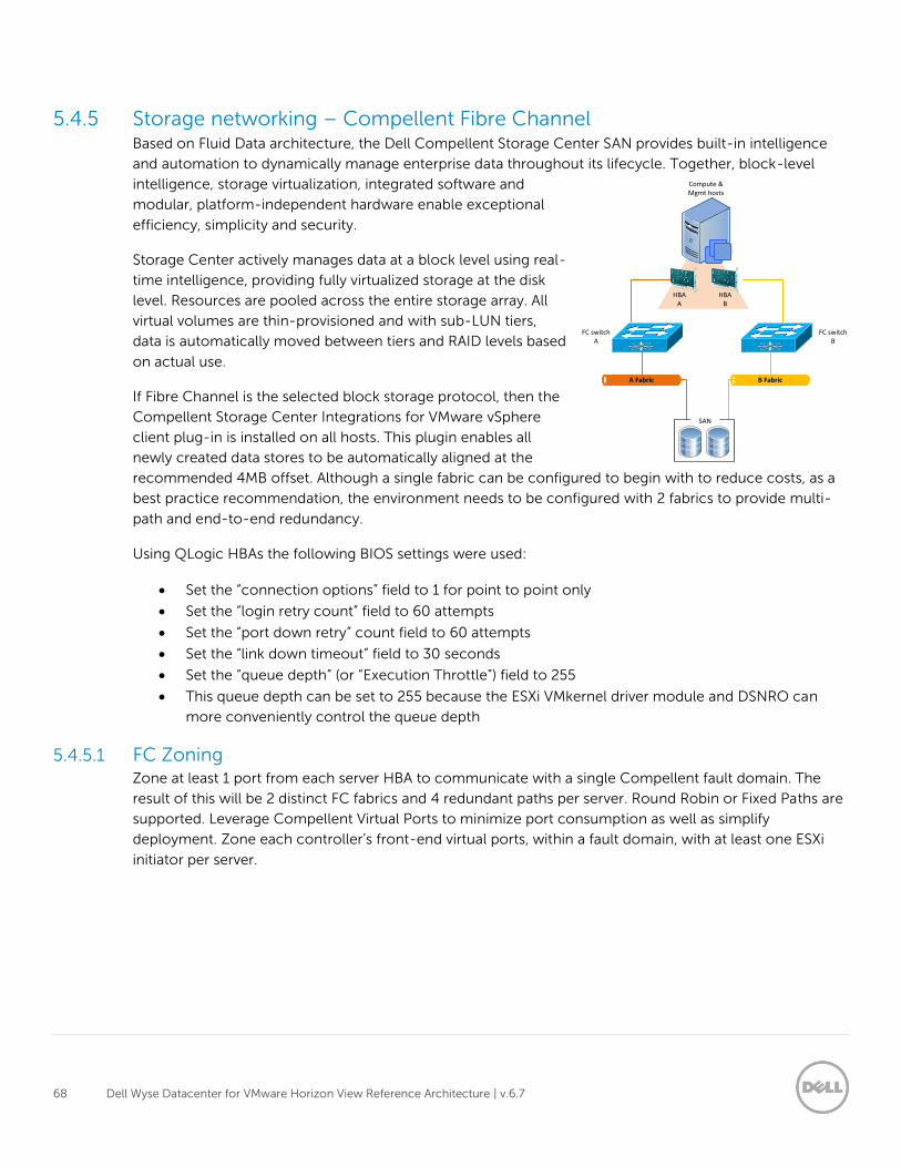
68 Dell Wyse Datacenter for VMware Horizon View Reference Architecture | v.6.7
5.4.5 Storage networking – Compellent Fibre Channel Based on Fluid Data architecture, the Dell Compellent Storage Center SAN provides built-in intelligence
and automation to dynamically manage enterprise data throughout its lifecycle. Together, block-level
intelligence, storage virtualization, integrated software and
modular, platform-independent hardware enable exceptional
efficiency, simplicity and security.
Storage Center actively manages data at a block level using real-
time intelligence, providing fully virtualized storage at the disk
level. Resources are pooled across the entire storage array. All
virtual volumes are thin-provisioned and with sub-LUN tiers,
data is automatically moved between tiers and RAID levels based
on actual use.
If Fibre Channel is the selected block storage protocol, then the
Compellent Storage Center Integrations for VMware vSphere
client plug-in is installed on all hosts. This plugin enables all
newly created data stores to be automatically aligned at the
recommended 4MB offset. Although a single fabric can be configured to begin with to reduce costs, as a
best practice recommendation, the environment needs to be configured with 2 fabrics to provide multi-
path and end-to-end redundancy.
Using QLogic HBAs the following BIOS settings were used:
Set the “connection options” field to 1 for point to point only
Set the “login retry count” field to 60 attempts
Set the “port down retry” count field to 60 attempts
Set the “link down timeout” field to 30 seconds
Set the “queue depth” (or “Execution Throttle”) field to 255
This queue depth can be set to 255 because the ESXi VMkernel driver module and DSNRO can
more conveniently control the queue depth
5.4.5.1 FC Zoning Zone at least 1 port from each server HBA to communicate with a single Compellent fault domain. The
result of this will be 2 distinct FC fabrics and 4 redundant paths per server. Round Robin or Fixed Paths are
supported. Leverage Compellent Virtual Ports to minimize port consumption as well as simplify
deployment. Zone each controller’s front-end virtual ports, within a fault domain, with at least one ESXi
initiator per server.
A Fabric
Compute & Mgmt hosts
FC switchA
B Fabric
SAN
FC switchB
HBAA
HBAB
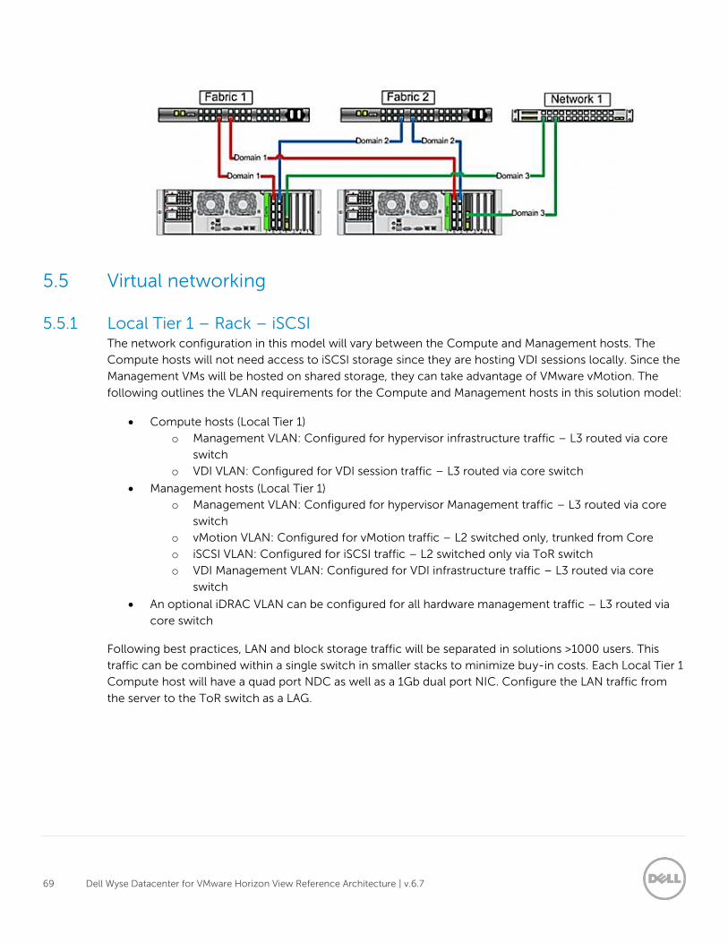
69 Dell Wyse Datacenter for VMware Horizon View Reference Architecture | v.6.7
5.5 Virtual networking
5.5.1 Local Tier 1 – Rack – iSCSI The network configuration in this model will vary between the Compute and Management hosts. The
Compute hosts will not need access to iSCSI storage since they are hosting VDI sessions locally. Since the
Management VMs will be hosted on shared storage, they can take advantage of VMware vMotion. The
following outlines the VLAN requirements for the Compute and Management hosts in this solution model:
Compute hosts (Local Tier 1)
o Management VLAN: Configured for hypervisor infrastructure traffic – L3 routed via core
switch
o VDI VLAN: Configured for VDI session traffic – L3 routed via core switch
Management hosts (Local Tier 1)
o Management VLAN: Configured for hypervisor Management traffic – L3 routed via core
switch
o vMotion VLAN: Configured for vMotion traffic – L2 switched only, trunked from Core
o iSCSI VLAN: Configured for iSCSI traffic – L2 switched only via ToR switch
o VDI Management VLAN: Configured for VDI infrastructure traffic – L3 routed via core
switch
An optional iDRAC VLAN can be configured for all hardware management traffic – L3 routed via
core switch
Following best practices, LAN and block storage traffic will be separated in solutions >1000 users. This
traffic can be combined within a single switch in smaller stacks to minimize buy-in costs. Each Local Tier 1
Compute host will have a quad port NDC as well as a 1Gb dual port NIC. Configure the LAN traffic from
the server to the ToR switch as a LAG.
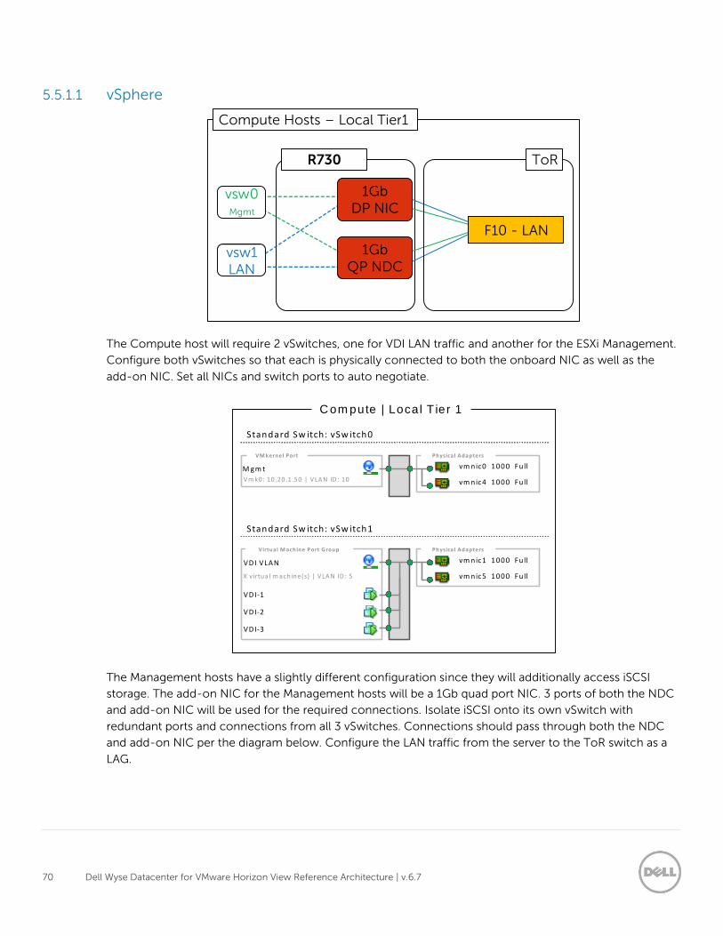
70 Dell Wyse Datacenter for VMware Horizon View Reference Architecture | v.6.7
5.5.1.1 vSphere
The Compute host will require 2 vSwitches, one for VDI LAN traffic and another for the ESXi Management.
Configure both vSwitches so that each is physically connected to both the onboard NIC as well as the
add-on NIC. Set all NICs and switch ports to auto negotiate.
The Management hosts have a slightly different configuration since they will additionally access iSCSI
storage. The add-on NIC for the Management hosts will be a 1Gb quad port NIC. 3 ports of both the NDC
and add-on NIC will be used for the required connections. Isolate iSCSI onto its own vSwitch with
redundant ports and connections from all 3 vSwitches. Connections should pass through both the NDC
and add-on NIC per the diagram below. Configure the LAN traffic from the server to the ToR switch as a
LAG.
vm nic0 1000 Fu ll
vm nic4 1000 Fu ll
Physica l A dapters
M gm t
VM kernel Port
Standard Sw itch: vSw itch0
V m k0: 10 .20 .1.50 | V LA N ID : 10
vm nic1 1000 Fu ll
vm nic5 1000 Fu ll
Physica l A dapters
VD I VLAN
Virtual M achine Port G roup
Standard Sw itch: vSw itch1
X v irtua l m achine(s) | V LA N ID : 5
C om pute | Loca l T ier 1
VD I-1
VD I-2
VD I-3
vsw 1
LAN
vsw 0
Mgmt
1 Gb QP NDC
R 730
1 Gb DP NIC
Compute Hosts – Local Tier 1
F 10 - LAN
ToR
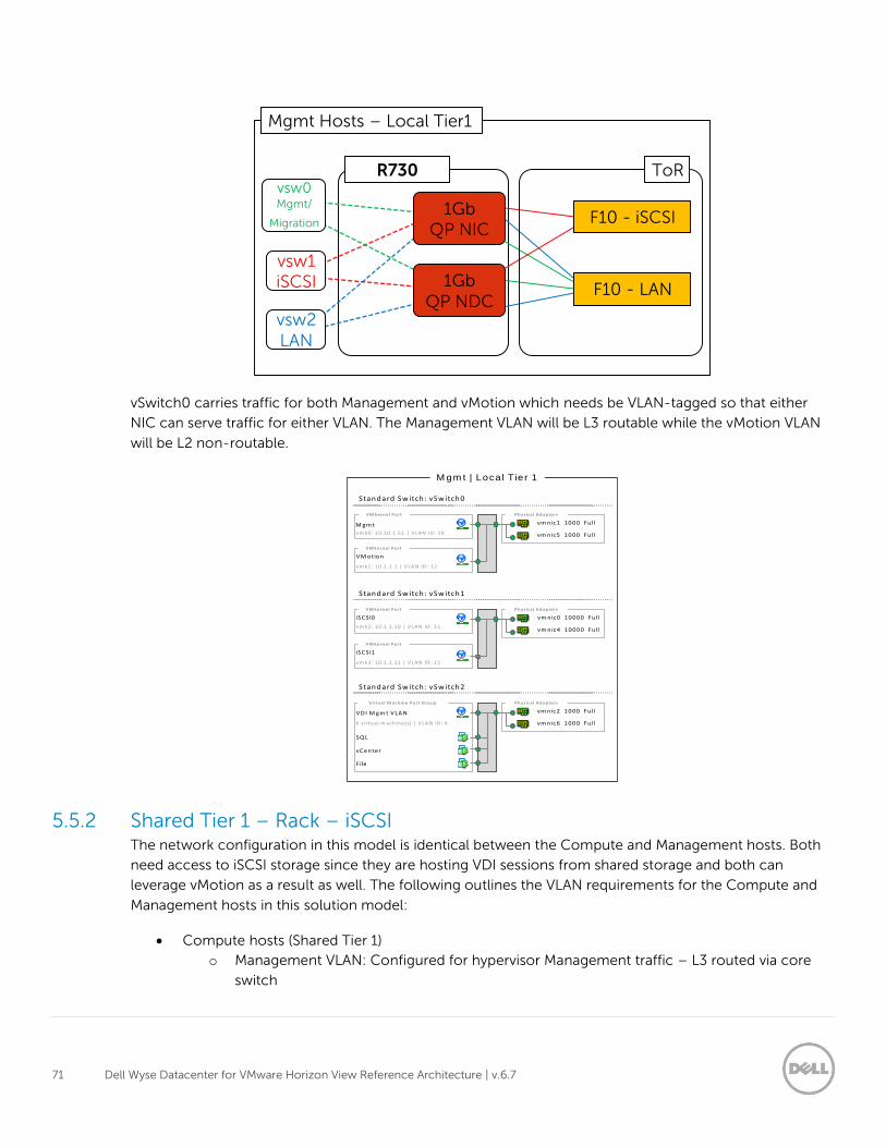
71 Dell Wyse Datacenter for VMware Horizon View Reference Architecture | v.6.7
vSwitch0 carries traffic for both Management and vMotion which needs be VLAN-tagged so that either
NIC can serve traffic for either VLAN. The Management VLAN will be L3 routable while the vMotion VLAN
will be L2 non-routable.
5.5.2 Shared Tier 1 – Rack – iSCSI The network configuration in this model is identical between the Compute and Management hosts. Both
need access to iSCSI storage since they are hosting VDI sessions from shared storage and both can
leverage vMotion as a result as well. The following outlines the VLAN requirements for the Compute and
Management hosts in this solution model:
Compute hosts (Shared Tier 1)
o Management VLAN: Configured for hypervisor Management traffic – L3 routed via core
switch
iSCSI0
VM kernel Port
vm k2: 10 .1.1 .10 | V LA N ID : 11
vm nic2 1000 Fu ll
vm nic6 1000 Fu ll
Physica l A dapters
VD I M gm t VLAN
Virtual M achine Port G roup
Standard Sw itch: vSw itch2
X v irtua l m achine(s) | V LA N ID : 6
M gm t | Loca l T ier 1
iSCSI1
VM kernel Port
vm k3: 10 .1.1 .11 | V LA N ID : 11
SQ L
vCenter
File
vm nic0 10000 Fu ll
vm nic4 10000 Fu ll
Physica l A dapters
Standard Sw itch: vSw itch1
vm nic1 1000 Fu ll
vm nic5 1000 Fu ll
Physica l A dapters
M gm t
VM kernel Port
Standard Sw itch: vSw itch0
vm k0: 10 .20 .1.51 | V LA N ID : 10
VM otion
VM kernel Port
vm k1: 10 .1.1 .1 | V LA N ID : 12
vsw 2
LAN
vsw 1
iSCSI
R 730
Mgmt Hosts – Local Tier 1
vsw 0 Mgmt /
Migration
F 10 - LAN
F 10 - iSCSI 1 Gb QP NIC
1 Gb QP NDC
ToR
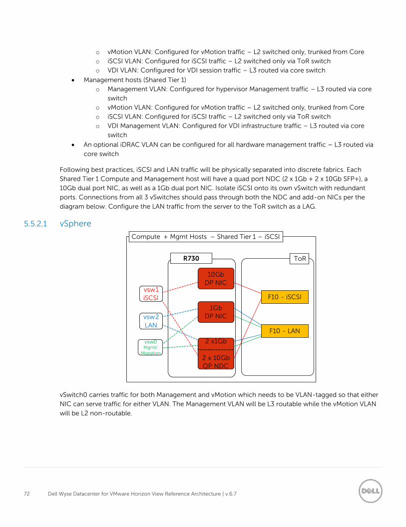
72 Dell Wyse Datacenter for VMware Horizon View Reference Architecture | v.6.7
o vMotion VLAN: Configured for vMotion traffic – L2 switched only, trunked from Core
o iSCSI VLAN: Configured for iSCSI traffic – L2 switched only via ToR switch
o VDI VLAN: Configured for VDI session traffic – L3 routed via core switch
Management hosts (Shared Tier 1)
o Management VLAN: Configured for hypervisor Management traffic – L3 routed via core
switch
o vMotion VLAN: Configured for vMotion traffic – L2 switched only, trunked from Core
o iSCSI VLAN: Configured for iSCSI traffic – L2 switched only via ToR switch
o VDI Management VLAN: Configured for VDI infrastructure traffic – L3 routed via core
switch
An optional iDRAC VLAN can be configured for all hardware management traffic – L3 routed via
core switch
Following best practices, iSCSI and LAN traffic will be physically separated into discrete fabrics. Each
Shared Tier 1 Compute and Management host will have a quad port NDC (2 x 1Gb + 2 x 10Gb SFP+), a
10Gb dual port NIC, as well as a 1Gb dual port NIC. Isolate iSCSI onto its own vSwitch with redundant
ports. Connections from all 3 vSwitches should pass through both the NDC and add-on NICs per the
diagram below. Configure the LAN traffic from the server to the ToR switch as a LAG.
5.5.2.1 vSphere
vSwitch0 carries traffic for both Management and vMotion which needs to be VLAN-tagged so that either
NIC can serve traffic for either VLAN. The Management VLAN will be L3 routable while the vMotion VLAN
will be L2 non-routable.
F 10 - LAN
F 10 - iSCSI vsw 1
iSCSI
10 Gb
DP NIC
vsw 0 Mgmt /
Migration
vsw 2
LAN
R 730
Compute + Mgmt Hosts – Shared Tier 1 – iSCSI
1 Gb DP NIC
2 x 1 Gb
2 x 10 Gb QP NDC
ToR
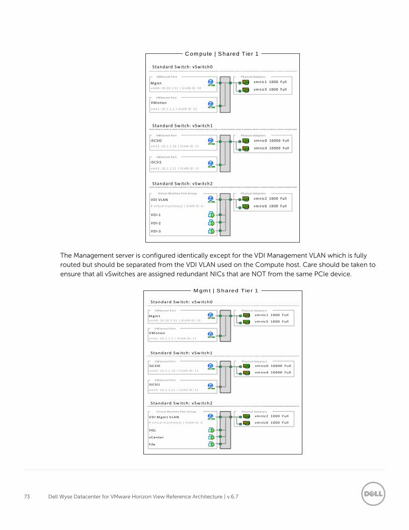
73 Dell Wyse Datacenter for VMware Horizon View Reference Architecture | v.6.7
The Management server is configured identically except for the VDI Management VLAN which is fully
routed but should be separated from the VDI VLAN used on the Compute host. Care should be taken to
ensure that all vSwitches are assigned redundant NICs that are NOT from the same PCIe device.
iSCSI0
VM kernel Port
vm k2: 10 .1.1 .10 | V LA N ID : 11
vm nic2 1000 Fu ll
vm nic6 1000 Fu ll
Physica l A dapters
VD I VLAN
Virtual M achine Port G roup
Standard Sw itch: vSw itch2
X v irtua l m achine(s) | V LA N ID : 6
C om pute | Shared T ier 1
iSCSI1
VM kernel Port
vm k3: 10 .1.1 .11 | V LA N ID : 11
VD I-1
VD I-2
VD I-3
vm nic0 10000 Fu ll
vm nic4 10000 Fu ll
Physica l A dapters
Standard Sw itch: vSw itch1
vm nic1 1000 Fu ll
vm nic5 1000 Fu ll
Physica l A dapters
M gm t
VM kernel Port
Standard Sw itch: vSw itch0
vm k0: 10 .20 .1.51 | V LA N ID : 10
VM otion
VM kernel Port
vm k1: 10 .1.1 .1 | V LA N ID : 12
iSCSI0
VM kernel Port
vm k2: 10 .1.1 .10 | V LA N ID : 11
vm nic2 1000 Fu ll
vm nic6 1000 Fu ll
Physica l A dapters
VD I M gm t VLAN
Virtual M achine Port G roup
Standard Sw itch: vSw itch2
X v irtua l m achine(s) | V LA N ID : 6
M gm t | Shared T ier 1
iSCSI1
VM kernel Port
vm k3: 10 .1.1 .11 | V LA N ID : 11
SQ L
vCenter
File
vm nic0 10000 Fu ll
vm nic4 10000 Fu ll
Physica l A dapters
Standard Sw itch: vSw itch1
vm nic1 1000 Fu ll
vm nic5 1000 Fu ll
Physica l A dapters
M gm t
VM kernel Port
Standard Sw itch: vSw itch0
vm k0: 10 .20 .1.51 | V LA N ID : 10
VM otion
VM kernel Port
vm k1: 10 .1.1 .1 | V LA N ID : 12
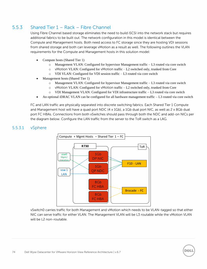
74 Dell Wyse Datacenter for VMware Horizon View Reference Architecture | v.6.7
5.5.3 Shared Tier 1 – Rack – Fibre Channel Using Fibre Channel based storage eliminates the need to build iSCSI into the network stack but requires
additional fabrics to be built out. The network configuration in this model is identical between the
Compute and Management hosts. Both need access to FC storage since they are hosting VDI sessions
from shared storage and both can leverage vMotion as a result as well. The following outlines the VLAN
requirements for the Compute and Management hosts in this solution model:
Compute hosts (Shared Tier 1)
o Management VLAN: Configured for hypervisor Management traffic – L3 routed via core switch
o vMotion VLAN: Configured for vMotion traffic – L2 switched only, trunked from Core
o VDI VLAN: Configured for VDI session traffic – L3 routed via core switch
Management hosts (Shared Tier 1)
o Management VLAN: Configured for hypervisor Management traffic – L3 routed via core switch
o vMotion VLAN: Configured for vMotion traffic – L2 switched only, trunked from Core
o VDI Management VLAN: Configured for VDI infrastructure traffic – L3 routed via core switch
An optional iDRAC VLAN can be configured for all hardware management traffic – L3 routed via core switch
FC and LAN traffic are physically separated into discrete switching fabrics. Each Shared Tier 1 Compute
and Management host will have a quad port NDC (4 x 1Gb), a 1Gb dual port NIC, as well as 2 x 8Gb dual
port FC HBAs. Connections from both vSwitches should pass through both the NDC and add-on NICs per
the diagram below. Configure the LAN traffic from the server to the ToR switch as a LAG.
5.5.3.1 vSphere
vSwitch0 carries traffic for both Management and vMotion which needs to be VLAN-tagged so that either
NIC can serve traffic for either VLAN. The Management VLAN will be L3 routable while the vMotion VLAN
will be L2 non-routable.
Compute + Mgmt Hosts – Shared Tier 1 – FC
F 10 - LAN
ToR
vsw 1
LAN
1 Gb
QP NDC
R 730
1 Gb
DP NIC
8 Gb
FC HBA
8 Gb
FC HBA
Brocade - FC
vsw 0 Mgmt /
migration
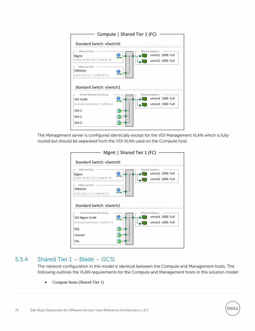
75 Dell Wyse Datacenter for VMware Horizon View Reference Architecture | v.6.7
The Management server is configured identically except for the VDI Management VLAN which is fully
routed but should be separated from the VDI VLAN used on the Compute host.
5.5.4 Shared Tier 1 – Blade – iSCSI The network configuration in this model is identical between the Compute and Management hosts. The
following outlines the VLAN requirements for the Compute and Management hosts in this solution model:
Compute hosts (Shared Tier 1)
vmnic4 1000 Full
vmnic5 1000 Full
Physical Adapters
VDI VLAN
Virtual Machine Port Group
Standard Switch: vSwitch2
X virtual machine(s) | VLAN ID: 6
Compute | Shared Tier 1 (FC)
VDI-1
VDI-2
VDI-3
vmnic2 1000 Full
vmnic3 1000 Full
Physical Adapters
Mgmt
VMkernel Port
Standard Switch: vSwitch0
vmk0: 10.20.1.51 | VLAN ID: 10
VMotionVMkernel Port
vmk1: 10.1.1.1 | VLAN ID: 12
vmnic4 1000 Full
vmnic5 1000 Full
Physical Adapters
VDI Mgmt VLAN
Virtual Machine Port Group
Standard Switch: vSwitch2
X virtual machine(s) | VLAN ID: 6
Mgmt | Shared Tier 1 (FC)
SQL
vCenter
File
vmnic2 1000 Full
vmnic3 1000 Full
Physical Adapters
Mgmt
VMkernel Port
Standard Switch: vSwitch0
vmk0: 10.20.1.51 | VLAN ID: 10
VMotionVMkernel Port
vmk1: 10.1.1.1 | VLAN ID: 12
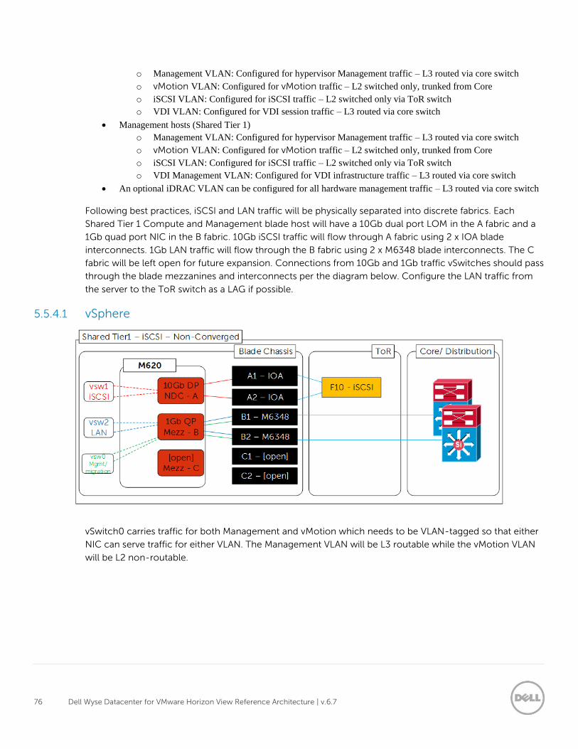
76 Dell Wyse Datacenter for VMware Horizon View Reference Architecture | v.6.7
o Management VLAN: Configured for hypervisor Management traffic – L3 routed via core switch
o vMotion VLAN: Configured for vMotion traffic – L2 switched only, trunked from Core
o iSCSI VLAN: Configured for iSCSI traffic – L2 switched only via ToR switch
o VDI VLAN: Configured for VDI session traffic – L3 routed via core switch
Management hosts (Shared Tier 1)
o Management VLAN: Configured for hypervisor Management traffic – L3 routed via core switch
o vMotion VLAN: Configured for vMotion traffic – L2 switched only, trunked from Core
o iSCSI VLAN: Configured for iSCSI traffic – L2 switched only via ToR switch
o VDI Management VLAN: Configured for VDI infrastructure traffic – L3 routed via core switch
An optional iDRAC VLAN can be configured for all hardware management traffic – L3 routed via core switch
Following best practices, iSCSI and LAN traffic will be physically separated into discrete fabrics. Each
Shared Tier 1 Compute and Management blade host will have a 10Gb dual port LOM in the A fabric and a
1Gb quad port NIC in the B fabric. 10Gb iSCSI traffic will flow through A fabric using 2 x IOA blade
interconnects. 1Gb LAN traffic will flow through the B fabric using 2 x M6348 blade interconnects. The C
fabric will be left open for future expansion. Connections from 10Gb and 1Gb traffic vSwitches should pass
through the blade mezzanines and interconnects per the diagram below. Configure the LAN traffic from
the server to the ToR switch as a LAG if possible.
5.5.4.1 vSphere
vSwitch0 carries traffic for both Management and vMotion which needs to be VLAN-tagged so that either
NIC can serve traffic for either VLAN. The Management VLAN will be L3 routable while the vMotion VLAN
will be L2 non-routable.
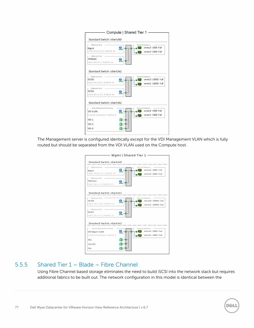
77 Dell Wyse Datacenter for VMware Horizon View Reference Architecture | v.6.7
The Management server is configured identically except for the VDI Management VLAN which is fully
routed but should be separated from the VDI VLAN used on the Compute host.
5.5.5 Shared Tier 1 – Blade – Fibre Channel Using Fibre Channel based storage eliminates the need to build iSCSI into the network stack but requires
additional fabrics to be built out. The network configuration in this model is identical between the
iSCSI0
VM kernel Port
vm k2: 10 .1.1 .10 | V LA N ID : 11
vm nic4 1000 Fu ll
vm nic5 1000 Fu ll
Physica l A dapters
VD I M gm t VLAN
Virtual M achine Port G roup
Standard Sw itch: vSw itch2
X v irtua l m achine(s) | V LA N ID : 6
M gm t | Shared T ier 1
iSCSI1
VM kernel Port
vm k3: 10 .1.1 .11 | V LA N ID : 11
SQ L
vC enter
File
vm nic0 10000 Fu ll
vm nic1 10000 Fu ll
Physica l A dapters
Standard Sw itch: vSw itch1
vm nic2 1000 Fu ll
vm nic3 1000 Fu ll
Physica l A dapters
M gm t
VM kernel Port
Standard Sw itch: vSw itch0
vm k0: 10 .20 .1.51 | V LA N ID : 10
VM otion
VM kernel Port
vm k1: 10 .1.1 .1 | V LA N ID : 12
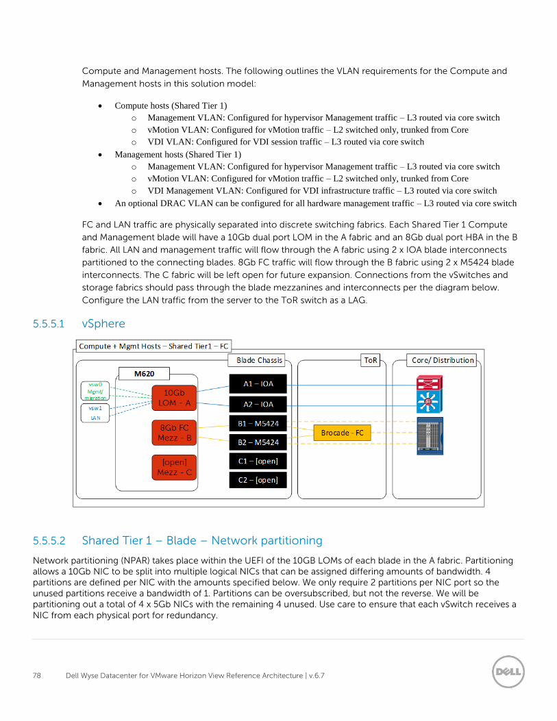
78 Dell Wyse Datacenter for VMware Horizon View Reference Architecture | v.6.7
Compute and Management hosts. The following outlines the VLAN requirements for the Compute and
Management hosts in this solution model:
Compute hosts (Shared Tier 1)
o Management VLAN: Configured for hypervisor Management traffic – L3 routed via core switch
o vMotion VLAN: Configured for vMotion traffic – L2 switched only, trunked from Core
o VDI VLAN: Configured for VDI session traffic – L3 routed via core switch
Management hosts (Shared Tier 1)
o Management VLAN: Configured for hypervisor Management traffic – L3 routed via core switch
o vMotion VLAN: Configured for vMotion traffic – L2 switched only, trunked from Core
o VDI Management VLAN: Configured for VDI infrastructure traffic – L3 routed via core switch
An optional DRAC VLAN can be configured for all hardware management traffic – L3 routed via core switch
FC and LAN traffic are physically separated into discrete switching fabrics. Each Shared Tier 1 Compute
and Management blade will have a 10Gb dual port LOM in the A fabric and an 8Gb dual port HBA in the B
fabric. All LAN and management traffic will flow through the A fabric using 2 x IOA blade interconnects
partitioned to the connecting blades. 8Gb FC traffic will flow through the B fabric using 2 x M5424 blade
interconnects. The C fabric will be left open for future expansion. Connections from the vSwitches and
storage fabrics should pass through the blade mezzanines and interconnects per the diagram below.
Configure the LAN traffic from the server to the ToR switch as a LAG.
5.5.5.1 vSphere
5.5.5.2 Shared Tier 1 – Blade – Network partitioning
Network partitioning (NPAR) takes place within the UEFI of the 10GB LOMs of each blade in the A fabric. Partitioning allows a 10Gb NIC to be split into multiple logical NICs that can be assigned differing amounts of bandwidth. 4 partitions are defined per NIC with the amounts specified below. We only require 2 partitions per NIC port so the unused partitions receive a bandwidth of 1. Partitions can be oversubscribed, but not the reverse. We will be partitioning out a total of 4 x 5Gb NICs with the remaining 4 unused. Use care to ensure that each vSwitch receives a NIC from each physical port for redundancy.
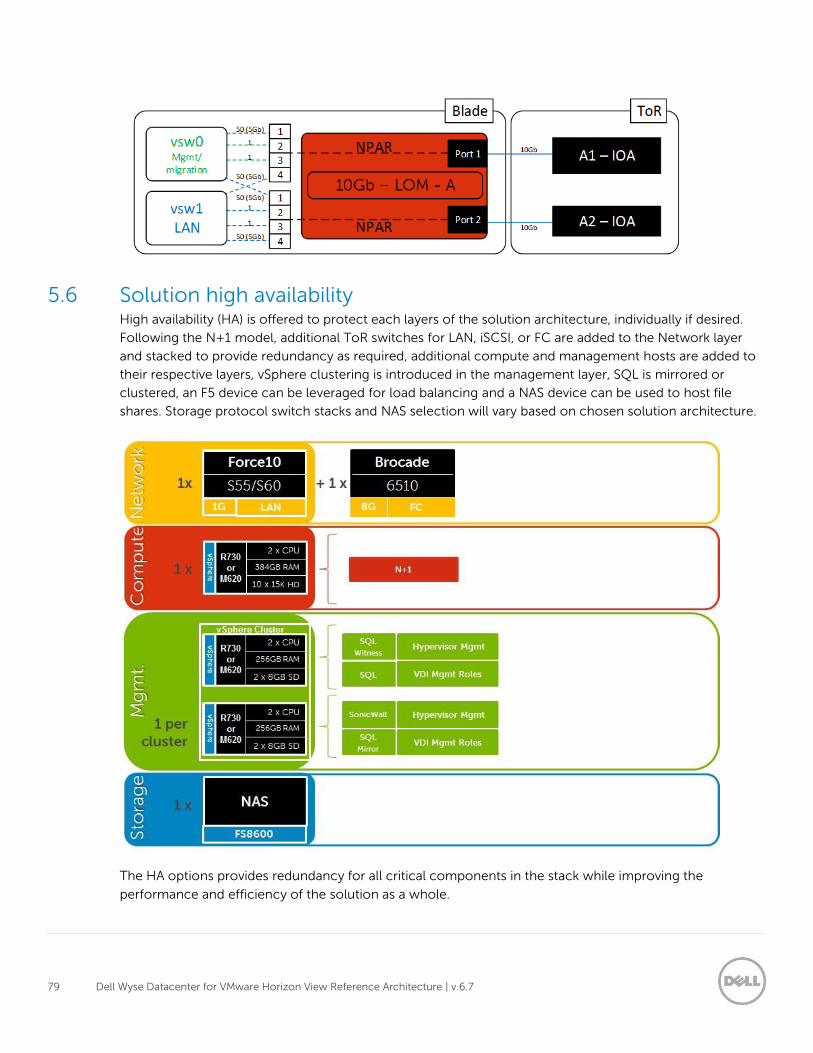
79 Dell Wyse Datacenter for VMware Horizon View Reference Architecture | v.6.7
5.6 Solution high availability High availability (HA) is offered to protect each layers of the solution architecture, individually if desired.
Following the N+1 model, additional ToR switches for LAN, iSCSI, or FC are added to the Network layer
and stacked to provide redundancy as required, additional compute and management hosts are added to
their respective layers, vSphere clustering is introduced in the management layer, SQL is mirrored or
clustered, an F5 device can be leveraged for load balancing and a NAS device can be used to host file
shares. Storage protocol switch stacks and NAS selection will vary based on chosen solution architecture.
The HA options provides redundancy for all critical components in the stack while improving the
performance and efficiency of the solution as a whole.
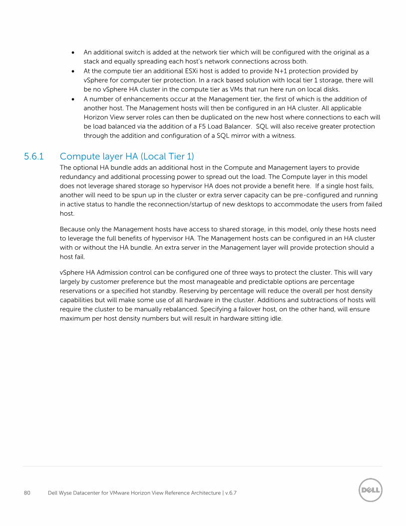
80 Dell Wyse Datacenter for VMware Horizon View Reference Architecture | v.6.7
An additional switch is added at the network tier which will be configured with the original as a
stack and equally spreading each host’s network connections across both.
At the compute tier an additional ESXi host is added to provide N+1 protection provided by
vSphere for computer tier protection. In a rack based solution with local tier 1 storage, there will
be no vSphere HA cluster in the compute tier as VMs that run here run on local disks.
A number of enhancements occur at the Management tier, the first of which is the addition of
another host. The Management hosts will then be configured in an HA cluster. All applicable
Horizon View server roles can then be duplicated on the new host where connections to each will
be load balanced via the addition of a F5 Load Balancer. SQL will also receive greater protection
through the addition and configuration of a SQL mirror with a witness.
5.6.1 Compute layer HA (Local Tier 1) The optional HA bundle adds an additional host in the Compute and Management layers to provide
redundancy and additional processing power to spread out the load. The Compute layer in this model
does not leverage shared storage so hypervisor HA does not provide a benefit here. If a single host fails,
another will need to be spun up in the cluster or extra server capacity can be pre-configured and running
in active status to handle the reconnection/startup of new desktops to accommodate the users from failed
host.
Because only the Management hosts have access to shared storage, in this model, only these hosts need
to leverage the full benefits of hypervisor HA. The Management hosts can be configured in an HA cluster
with or without the HA bundle. An extra server in the Management layer will provide protection should a
host fail.
vSphere HA Admission control can be configured one of three ways to protect the cluster. This will vary
largely by customer preference but the most manageable and predictable options are percentage
reservations or a specified hot standby. Reserving by percentage will reduce the overall per host density
capabilities but will make some use of all hardware in the cluster. Additions and subtractions of hosts will
require the cluster to be manually rebalanced. Specifying a failover host, on the other hand, will ensure
maximum per host density numbers but will result in hardware sitting idle.
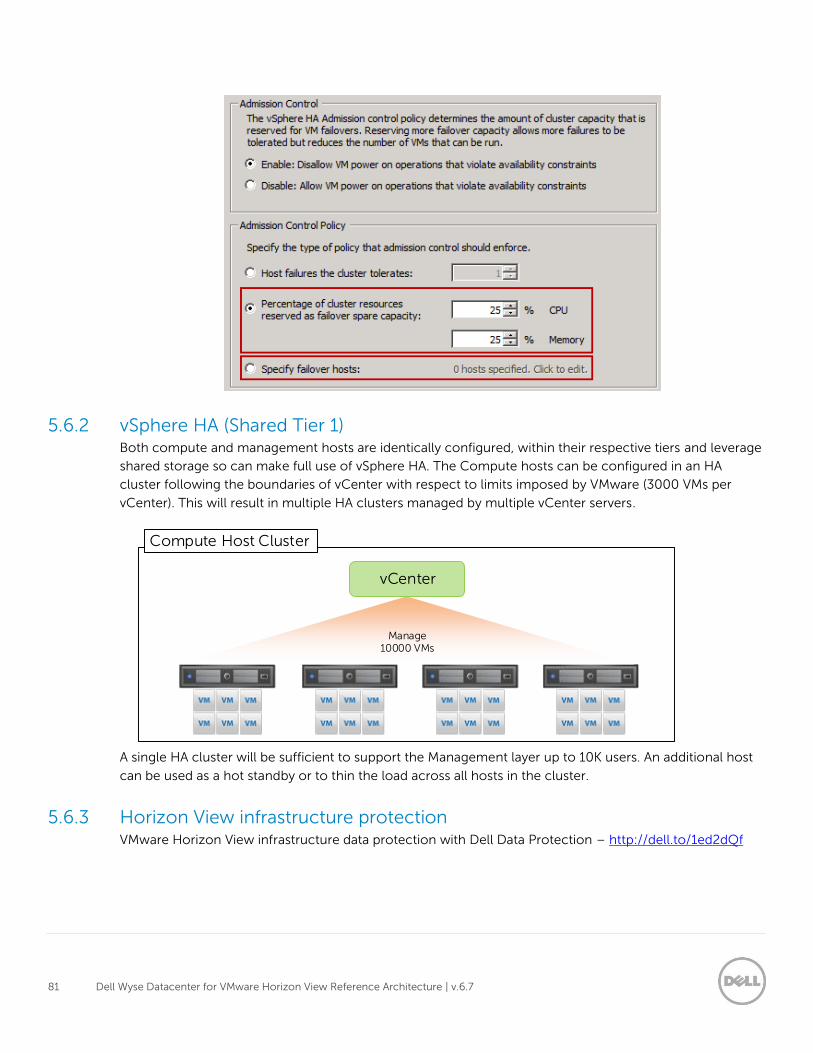
81 Dell Wyse Datacenter for VMware Horizon View Reference Architecture | v.6.7
5.6.2 vSphere HA (Shared Tier 1) Both compute and management hosts are identically configured, within their respective tiers and leverage
shared storage so can make full use of vSphere HA. The Compute hosts can be configured in an HA
cluster following the boundaries of vCenter with respect to limits imposed by VMware (3000 VMs per
vCenter). This will result in multiple HA clusters managed by multiple vCenter servers.
A single HA cluster will be sufficient to support the Management layer up to 10K users. An additional host
can be used as a hot standby or to thin the load across all hosts in the cluster.
5.6.3 Horizon View infrastructure protection VMware Horizon View infrastructure data protection with Dell Data Protection – http://dell.to/1ed2dQf
Compute Host Cluster
Manage 10000 VMs
vCenter
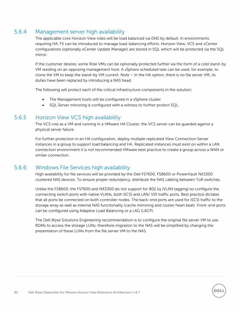
82 Dell Wyse Datacenter for VMware Horizon View Reference Architecture | v.6.7
5.6.4 Management server high availability The applicable core Horizon View roles will be load balanced via DNS by default. In environments
requiring HA, F5 can be introduced to manage load-balancing efforts. Horizon View, VCS and vCenter
configurations (optionally vCenter Update Manager) are stored in SQL which will be protected via the SQL
mirror.
If the customer desires, some Role VMs can be optionally protected further via the form of a cold stand-by
VM residing on an opposing management host. A vSphere scheduled task can be used, for example, to
clone the VM to keep the stand-by VM current. Note – In the HA option, there is no file server VM, its
duties have been replaced by introducing a NAS head.
The following will protect each of the critical infrastructure components in the solution:
The Management hosts will be configured in a vSphere cluster.
SQL Server mirroring is configured with a witness to further protect SQL.
5.6.5 Horizon View VCS high availability The VCS role as a VM and running in a VMware HA Cluster, the VCS server can be guarded against a
physical server failure.
For further protection in an HA configuration, deploy multiple replicated View Connection Server
instances in a group to support load balancing and HA. Replicated instances must exist on within a LAN
connection environment it is not recommended VMware best practice to create a group across a WAN or
similar connection.
5.6.6 Windows File Services high availability High availability for file services will be provided by the Dell FS7600, FS8600 or PowerVault NX3300
clustered NAS devices. To ensure proper redundancy, distribute the NAS cabling between ToR switches.
Unlike the FS8600, the FS7600 and NX3300 do not support for 802.1q (VLAN tagging) so configure the
connecting switch ports with native VLANs, both iSCSI and LAN/ VDI traffic ports. Best practice dictates
that all ports be connected on both controller nodes. The back-end ports are used for iSCSI traffic to the
storage array as well as internal NAS functionality (cache mirroring and cluster heart beat). Front-end ports
can be configured using Adaptive Load Balancing or a LAG (LACP).
The Dell Wyse Solutions Engineering recommendation is to configure the original file server VM to use
RDMs to access the storage LUNs, therefore migration to the NAS will be simplified by changing the
presentation of these LUNs from the file server VM to the NAS.
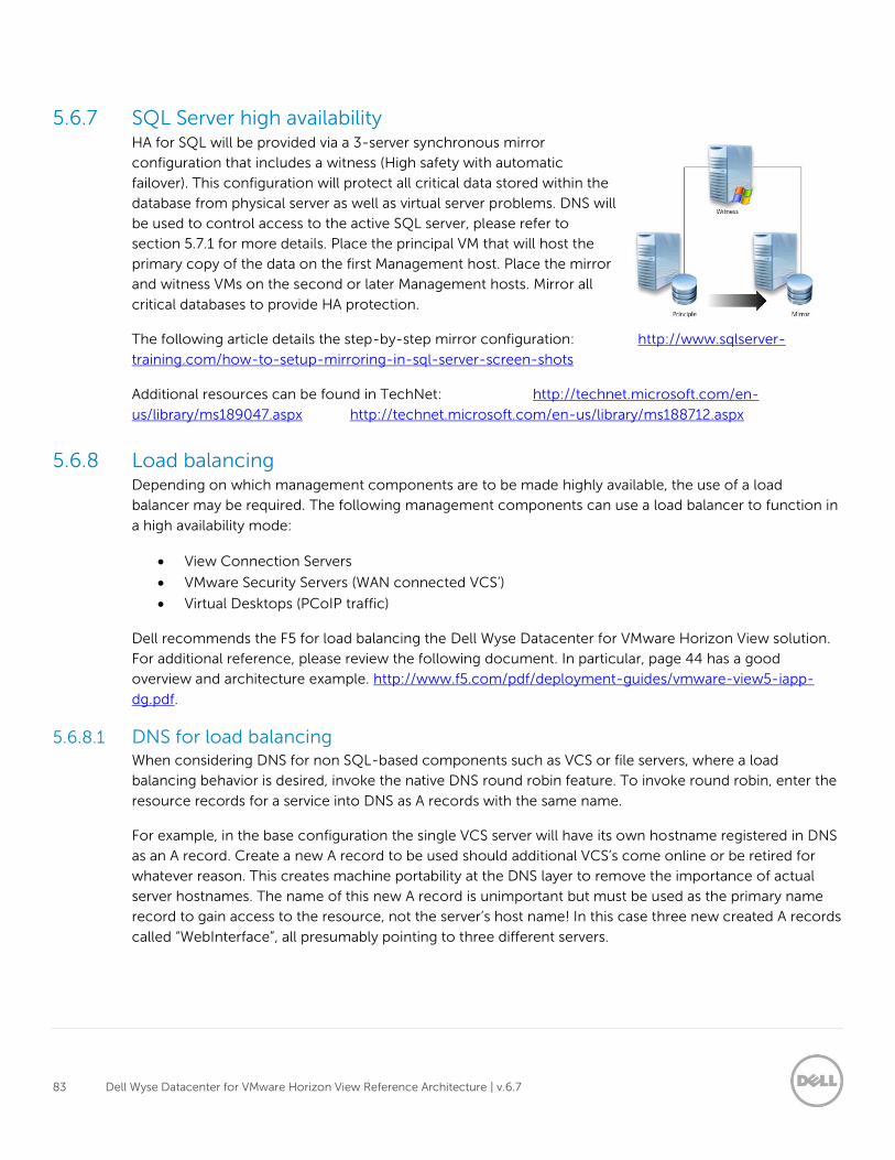
83 Dell Wyse Datacenter for VMware Horizon View Reference Architecture | v.6.7
5.6.7 SQL Server high availability HA for SQL will be provided via a 3-server synchronous mirror
configuration that includes a witness (High safety with automatic
failover). This configuration will protect all critical data stored within the
database from physical server as well as virtual server problems. DNS will
be used to control access to the active SQL server, please refer to
section 5.7.1 for more details. Place the principal VM that will host the
primary copy of the data on the first Management host. Place the mirror
and witness VMs on the second or later Management hosts. Mirror all
critical databases to provide HA protection.
The following article details the step-by-step mirror configuration: http://www.sqlserver-
training.com/how-to-setup-mirroring-in-sql-server-screen-shots
Additional resources can be found in TechNet: http://technet.microsoft.com/en-
us/library/ms189047.aspx http://technet.microsoft.com/en-us/library/ms188712.aspx
5.6.8 Load balancing Depending on which management components are to be made highly available, the use of a load
balancer may be required. The following management components can use a load balancer to function in
a high availability mode:
View Connection Servers
VMware Security Servers (WAN connected VCS’)
Virtual Desktops (PCoIP traffic)
Dell recommends the F5 for load balancing the Dell Wyse Datacenter for VMware Horizon View solution.
For additional reference, please review the following document. In particular, page 44 has a good
overview and architecture example. http://www.f5.com/pdf/deployment-guides/vmware-view5-iapp-
dg.pdf.
5.6.8.1 DNS for load balancing When considering DNS for non SQL-based components such as VCS or file servers, where a load
balancing behavior is desired, invoke the native DNS round robin feature. To invoke round robin, enter the
resource records for a service into DNS as A records with the same name.
For example, in the base configuration the single VCS server will have its own hostname registered in DNS
as an A record. Create a new A record to be used should additional VCS’s come online or be retired for
whatever reason. This creates machine portability at the DNS layer to remove the importance of actual
server hostnames. The name of this new A record is unimportant but must be used as the primary name
record to gain access to the resource, not the server’s host name! In this case three new created A records
called “WebInterface”, all presumably pointing to three different servers.
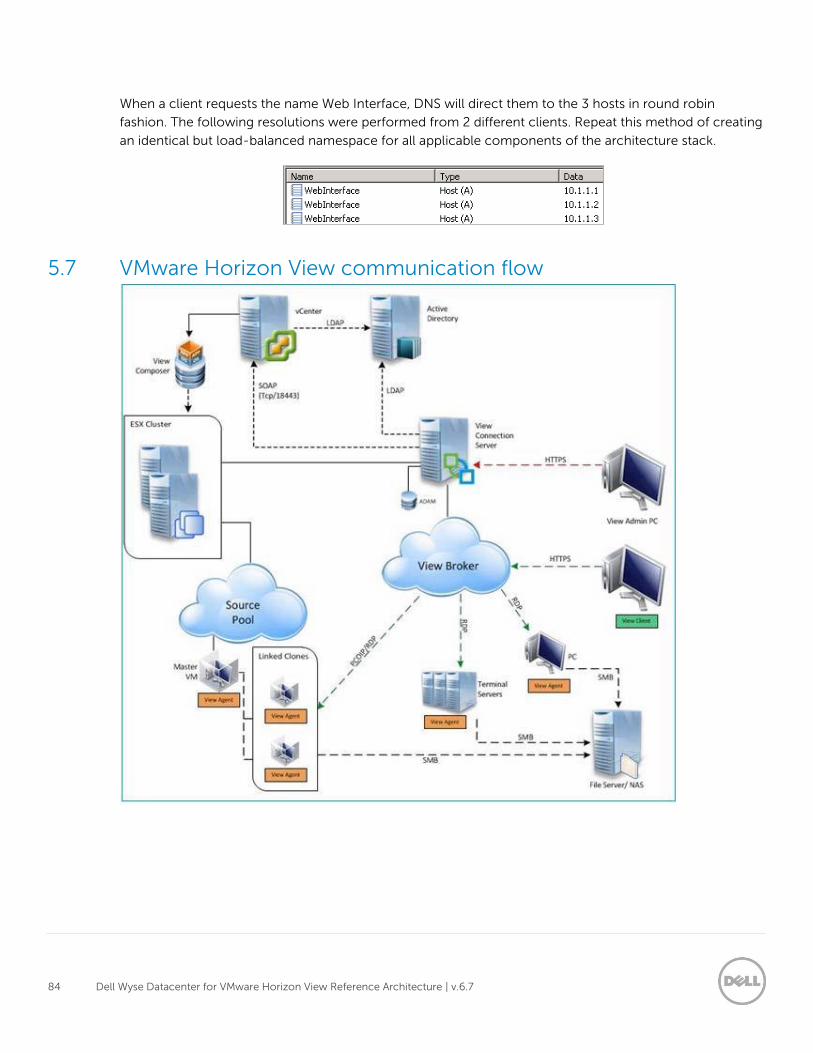
84 Dell Wyse Datacenter for VMware Horizon View Reference Architecture | v.6.7
When a client requests the name Web Interface, DNS will direct them to the 3 hosts in round robin
fashion. The following resolutions were performed from 2 different clients. Repeat this method of creating
an identical but load-balanced namespace for all applicable components of the architecture stack.
5.7 VMware Horizon View communication flow
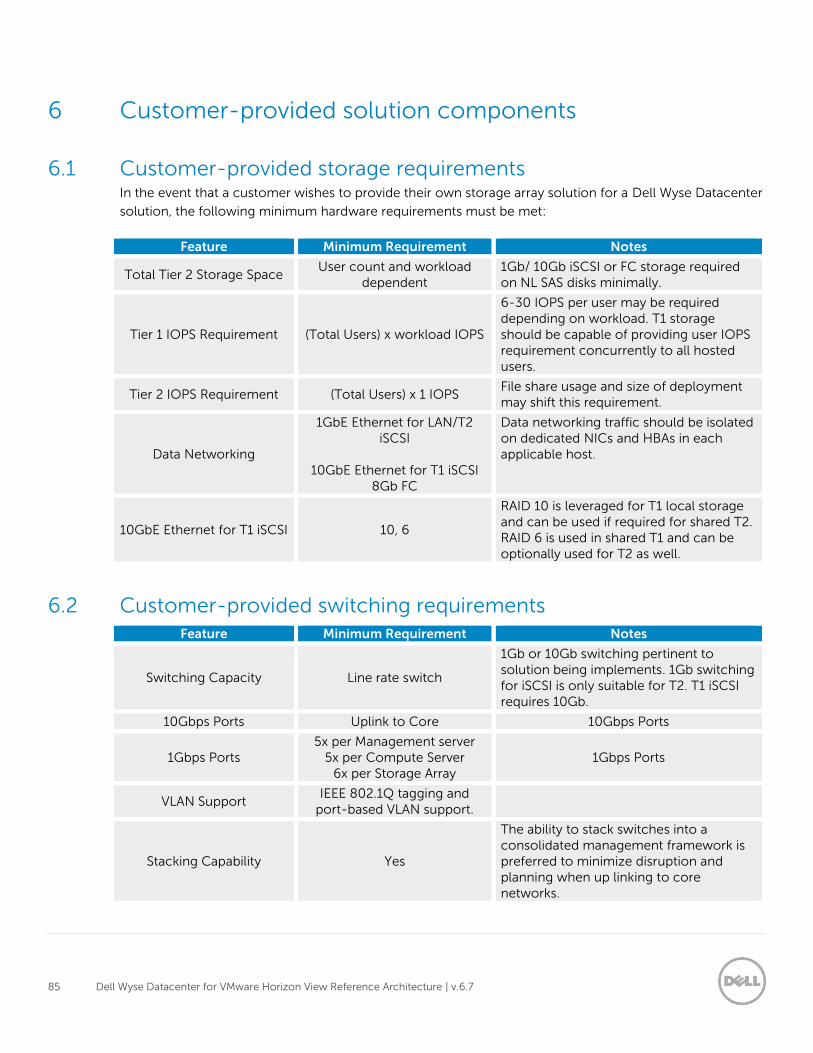
85 Dell Wyse Datacenter for VMware Horizon View Reference Architecture | v.6.7
6 Customer-provided solution components
6.1 Customer-provided storage requirements In the event that a customer wishes to provide their own storage array solution for a Dell Wyse Datacenter
solution, the following minimum hardware requirements must be met:
Feature Minimum Requirement Notes
Total Tier 2 Storage Space User count and workload
dependent 1Gb/ 10Gb iSCSI or FC storage required on NL SAS disks minimally.
Tier 1 IOPS Requirement (Total Users) x workload IOPS
6-30 IOPS per user may be required depending on workload. T1 storage should be capable of providing user IOPS requirement concurrently to all hosted users.
Tier 2 IOPS Requirement (Total Users) x 1 IOPS File share usage and size of deployment may shift this requirement.
Data Networking
1GbE Ethernet for LAN/T2 iSCSI
10GbE Ethernet for T1 iSCSI
8Gb FC
Data networking traffic should be isolated on dedicated NICs and HBAs in each applicable host.
10GbE Ethernet for T1 iSCSI 10, 6
RAID 10 is leveraged for T1 local storage and can be used if required for shared T2. RAID 6 is used in shared T1 and can be optionally used for T2 as well.
6.2 Customer-provided switching requirements Feature Minimum Requirement Notes
Switching Capacity Line rate switch
1Gb or 10Gb switching pertinent to solution being implements. 1Gb switching for iSCSI is only suitable for T2. T1 iSCSI requires 10Gb.
10Gbps Ports Uplink to Core 10Gbps Ports
1Gbps Ports 5x per Management server
5x per Compute Server 6x per Storage Array
1Gbps Ports
VLAN Support IEEE 802.1Q tagging and
port-based VLAN support.
Stacking Capability Yes
The ability to stack switches into a consolidated management framework is preferred to minimize disruption and planning when up linking to core networks.
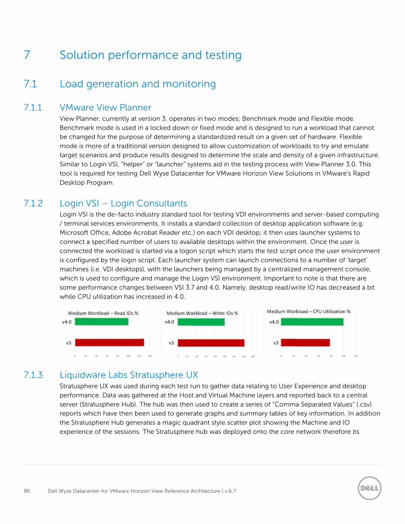
86 Dell Wyse Datacenter for VMware Horizon View Reference Architecture | v.6.7
7 Solution performance and testing
7.1 Load generation and monitoring
7.1.1 VMware View Planner View Planner, currently at version 3, operates in two modes; Benchmark mode and Flexible mode.
Benchmark mode is used in a locked down or fixed mode and is designed to run a workload that cannot
be changed for the purpose of determining a standardized result on a given set of hardware. Flexible
mode is more of a traditional version designed to allow customization of workloads to try and emulate
target scenarios and produce results designed to determine the scale and density of a given infrastructure.
Similar to Login VSI, “helper” or “launcher” systems aid in the testing process with View Planner 3.0. This
tool is required for testing Dell Wyse Datacenter for VMware Horizon View Solutions in VMware’s Rapid
Desktop Program.
7.1.2 Login VSI – Login Consultants Login VSI is the de-facto industry standard tool for testing VDI environments and server-based computing
/ terminal services environments. It installs a standard collection of desktop application software (e.g.
Microsoft Office, Adobe Acrobat Reader etc.) on each VDI desktop; it then uses launcher systems to
connect a specified number of users to available desktops within the environment. Once the user is
connected the workload is started via a logon script which starts the test script once the user environment
is configured by the login script. Each launcher system can launch connections to a number of 'target'
machines (i.e. VDI desktops), with the launchers being managed by a centralized management console,
which is used to configure and manage the Login VSI environment. Important to note is that there are
some performance changes between VSI 3.7 and 4.0. Namely, desktop read/write IO has decreased a bit
while CPU utilization has increased in 4.0.
7.1.3 Liquidware Labs Stratusphere UX Stratusphere UX was used during each test run to gather data relating to User Experience and desktop
performance. Data was gathered at the Host and Virtual Machine layers and reported back to a central
server (Stratusphere Hub). The hub was then used to create a series of “Comma Separated Values” (.csv)
reports which have then been used to generate graphs and summary tables of key information. In addition
the Stratusphere Hub generates a magic quadrant style scatter plot showing the Machine and IO
experience of the sessions. The Stratusphere hub was deployed onto the core network therefore its
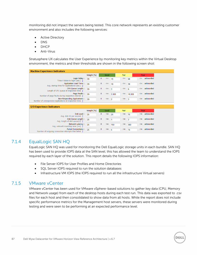
87 Dell Wyse Datacenter for VMware Horizon View Reference Architecture | v.6.7
monitoring did not impact the servers being tested. This core network represents an existing customer
environment and also includes the following services:
Active Directory
DNS
DHCP
Anti-Virus
Stratusphere UX calculates the User Experience by monitoring key metrics within the Virtual Desktop
environment, the metrics and their thresholds are shown in the following screen shot:
7.1.4 EqualLogic SAN HQ EqualLogic SAN HQ was used for monitoring the Dell EqualLogic storage units in each bundle. SAN HQ
has been used to provide IOPS data at the SAN level; this has allowed the team to understand the IOPS
required by each layer of the solution. This report details the following IOPS information:
File Server IOPS for User Profiles and Home Directories
SQL Server IOPS required to run the solution databases
Infrastructure VM IOPS (the IOPS required to run all the infrastructure Virtual servers)
7.1.5 VMware vCenter VMware vCenter has been used for VMware vSphere-based solutions to gather key data (CPU, Memory
and Network usage) from each of the desktop hosts during each test run. This data was exported to .csv
files for each host and then consolidated to show data from all hosts. While the report does not include
specific performance metrics for the Management host servers, these servers were monitored during
testing and were seen to be performing at an expected performance level.
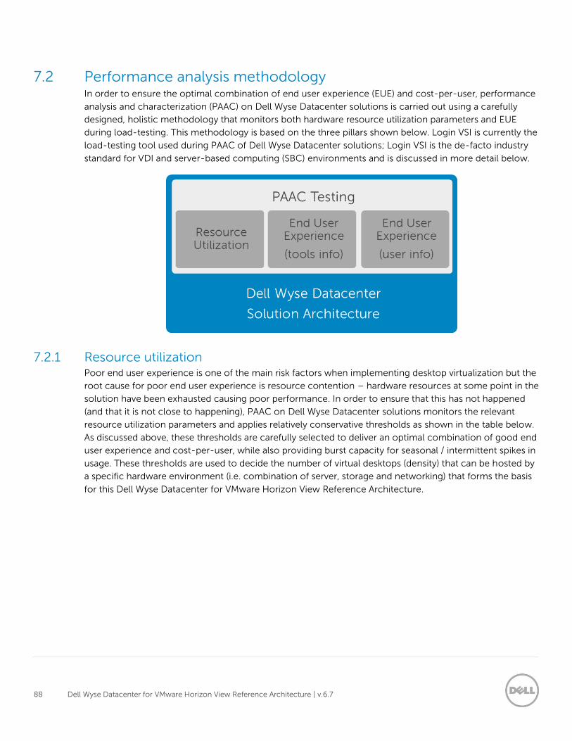
88 Dell Wyse Datacenter for VMware Horizon View Reference Architecture | v.6.7
7.2 Performance analysis methodology In order to ensure the optimal combination of end user experience (EUE) and cost-per-user, performance
analysis and characterization (PAAC) on Dell Wyse Datacenter solutions is carried out using a carefully
designed, holistic methodology that monitors both hardware resource utilization parameters and EUE
during load-testing. This methodology is based on the three pillars shown below. Login VSI is currently the
load-testing tool used during PAAC of Dell Wyse Datacenter solutions; Login VSI is the de-facto industry
standard for VDI and server-based computing (SBC) environments and is discussed in more detail below.
7.2.1 Resource utilization Poor end user experience is one of the main risk factors when implementing desktop virtualization but the
root cause for poor end user experience is resource contention – hardware resources at some point in the
solution have been exhausted causing poor performance. In order to ensure that this has not happened
(and that it is not close to happening), PAAC on Dell Wyse Datacenter solutions monitors the relevant
resource utilization parameters and applies relatively conservative thresholds as shown in the table below.
As discussed above, these thresholds are carefully selected to deliver an optimal combination of good end
user experience and cost-per-user, while also providing burst capacity for seasonal / intermittent spikes in
usage. These thresholds are used to decide the number of virtual desktops (density) that can be hosted by
a specific hardware environment (i.e. combination of server, storage and networking) that forms the basis
for this Dell Wyse Datacenter for VMware Horizon View Reference Architecture.
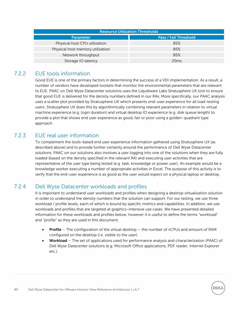
89 Dell Wyse Datacenter for VMware Horizon View Reference Architecture | v.6.7
Resource Utilization Thresholds
Parameter Pass / Fail Threshold
Physical host CPU utilization 85%
Physical host memory utilization 85%
Network throughput 85%
Storage IO latency 20ms
7.2.2 EUE tools information Good EUE is one of the primary factors in determining the success of a VDI implementation. As a result, a
number of vendors have developed toolsets that monitor the environmental parameters that are relevant
to EUE. PAAC on Dell Wyse Datacenter solutions uses the Liquidware Labs Stratusphere UX tool to ensure
that good EUE is delivered for the density numbers defined in our RAs. More specifically, our PAAC analysis
uses a scatter plot provided by Stratusphere UX which presents end-user experience for all load-testing
users. Stratusphere UX does this by algorithmically combining relevant parameters in relation to virtual
machine experience (e.g. login duration) and virtual desktop IO experience (e.g. disk queue length) to
provide a plot that shows end user experience as good, fair or poor using a golden-quadrant type
approach.
7.2.3 EUE real user information To complement the tools-based end user experience information gathered using Stratusphere UX (as
described above) and to provide further certainty around the performance of Dell Wyse Datacenter
solutions, PAAC on our solutions also involves a user logging into one of the solutions when they are fully
loaded (based on the density specified in the relevant RA) and executing user activities that are
representative of the user type being tested (e.g. task, knowledge or power user). An example would be a
knowledge worker executing a number of appropriate activities in Excel. The purpose of this activity is to
verify that the end-user experience is as good as the user would expect on a physical laptop or desktop.
7.2.4 Dell Wyse Datacenter workloads and profiles It is important to understand user workloads and profiles when designing a desktop virtualization solution
in order to understand the density numbers that the solution can support. For our testing, we use three
workload / profile levels, each of which is bound by specific metrics and capabilities. In addition, we use
workloads and profiles that are targeted at graphics-intensive use cases. We have presented detailed
information for these workloads and profiles below, however it is useful to define the terms “workload”
and “profile” as they are used in this document.
Profile – The configuration of the virtual desktop – the number of vCPUs and amount of RAM
configured on the desktop (i.e. visible to the user).
Workload – The set of applications used for performance analysis and characterization (PAAC) of
Dell Wyse Datacenter solutions (e.g. Microsoft Office applications, PDF reader, Internet Explorer
etc.).
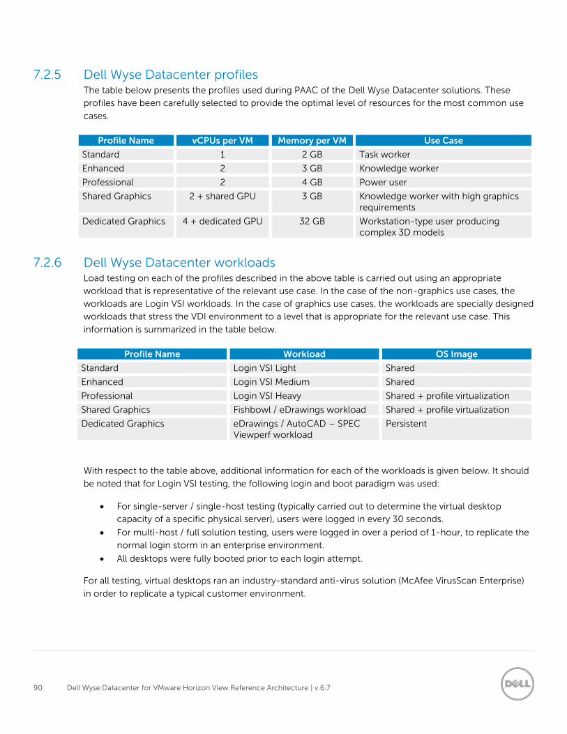
90 Dell Wyse Datacenter for VMware Horizon View Reference Architecture | v.6.7
7.2.5 Dell Wyse Datacenter profiles The table below presents the profiles used during PAAC of the Dell Wyse Datacenter solutions. These
profiles have been carefully selected to provide the optimal level of resources for the most common use
cases.
Profile Name vCPUs per VM Memory per VM Use Case
Standard 1 2 GB Task worker
Enhanced 2 3 GB Knowledge worker
Professional 2 4 GB Power user
Shared Graphics 2 + shared GPU 3 GB Knowledge worker with high graphics requirements
Dedicated Graphics 4 + dedicated GPU 32 GB Workstation-type user producing complex 3D models
7.2.6 Dell Wyse Datacenter workloads Load testing on each of the profiles described in the above table is carried out using an appropriate
workload that is representative of the relevant use case. In the case of the non-graphics use cases, the
workloads are Login VSI workloads. In the case of graphics use cases, the workloads are specially designed
workloads that stress the VDI environment to a level that is appropriate for the relevant use case. This
information is summarized in the table below.
Profile Name Workload OS Image
Standard Login VSI Light Shared
Enhanced Login VSI Medium Shared
Professional Login VSI Heavy Shared + profile virtualization
Shared Graphics Fishbowl / eDrawings workload Shared + profile virtualization
Dedicated Graphics eDrawings / AutoCAD – SPEC Viewperf workload
Persistent
With respect to the table above, additional information for each of the workloads is given below. It should
be noted that for Login VSI testing, the following login and boot paradigm was used:
For single-server / single-host testing (typically carried out to determine the virtual desktop
capacity of a specific physical server), users were logged in every 30 seconds.
For multi-host / full solution testing, users were logged in over a period of 1-hour, to replicate the
normal login storm in an enterprise environment.
All desktops were fully booted prior to each login attempt.
For all testing, virtual desktops ran an industry-standard anti-virus solution (McAfee VirusScan Enterprise)
in order to replicate a typical customer environment.
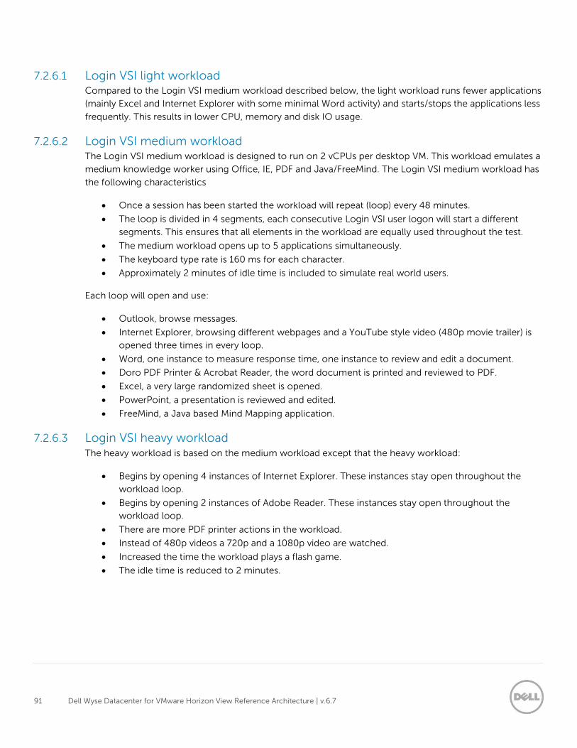
91 Dell Wyse Datacenter for VMware Horizon View Reference Architecture | v.6.7
7.2.6.1 Login VSI light workload Compared to the Login VSI medium workload described below, the light workload runs fewer applications
(mainly Excel and Internet Explorer with some minimal Word activity) and starts/stops the applications less
frequently. This results in lower CPU, memory and disk IO usage.
7.2.6.2 Login VSI medium workload The Login VSI medium workload is designed to run on 2 vCPUs per desktop VM. This workload emulates a
medium knowledge worker using Office, IE, PDF and Java/FreeMind. The Login VSI medium workload has
the following characteristics
Once a session has been started the workload will repeat (loop) every 48 minutes.
The loop is divided in 4 segments, each consecutive Login VSI user logon will start a different
segments. This ensures that all elements in the workload are equally used throughout the test.
The medium workload opens up to 5 applications simultaneously.
The keyboard type rate is 160 ms for each character.
Approximately 2 minutes of idle time is included to simulate real world users.
Each loop will open and use:
Outlook, browse messages.
Internet Explorer, browsing different webpages and a YouTube style video (480p movie trailer) is
opened three times in every loop.
Word, one instance to measure response time, one instance to review and edit a document.
Doro PDF Printer & Acrobat Reader, the word document is printed and reviewed to PDF.
Excel, a very large randomized sheet is opened.
PowerPoint, a presentation is reviewed and edited.
FreeMind, a Java based Mind Mapping application.
7.2.6.3 Login VSI heavy workload The heavy workload is based on the medium workload except that the heavy workload:
Begins by opening 4 instances of Internet Explorer. These instances stay open throughout the
workload loop.
Begins by opening 2 instances of Adobe Reader. These instances stay open throughout the
workload loop.
There are more PDF printer actions in the workload.
Instead of 480p videos a 720p and a 1080p video are watched.
Increased the time the workload plays a flash game.
The idle time is reduced to 2 minutes.
92 Dell Wyse Datacenter for VMware Horizon View Reference Architecture | v.6.7
7.2.7 Workloads running on shared graphics profile Graphics hardware vendors (e.g. NVIDIA) typically market a number of graphics cards that are targeted at
different user segments. Consequently, it is necessary to provide two shared graphics workloads – one for
mid-range cards and the other for high-end cards.
Mid-Range Shared Graphics Workload – The mid-range shared graphics workload is a modified Login VSI
medium workload with 60 seconds of graphics-intensive activity (Microsoft Fishbowl at
http://ie.microsoft.com/testdrive/performance/fishbowl/) added to each loop.
High-End Shared Graphics Workload – The high-end shared graphics workload consists of one desktop
running Heaven Benchmark and n-1 desktops running eDrawings Advanced Animation activity where n =
per-host virtual desktop density being tested at any specific time.
7.2.8 Workloads running on dedicated graphics profile Similarly for pass-through graphics, two workloads have been defined in order to align with graphics cards
of differing capabilities.
Mid-Range Pass-through Graphics Workload – The mid-range pass-through graphics workload consists
of one desktop running Heaven Benchmark and n-1 desktops running eDrawings Advanced Animation
activity where n = per-host virtual desktop density being tested at any specific time.
High-End Pass-through Graphics Workload – One desktop running Viewperf benchmark; n-1 desktops
running AutoCAD auto-rotate activity where n = per host virtual desktop density being tested at any
specific time.
7.3 Testing and validation
7.3.1 Testing process The purpose of the single server testing is to validate the architectural assumptions made around the
server stack. Each user load is tested against 4 runs. A pilot run to validate that the infrastructure is
functioning and valid data can be captured and 3 subsequent runs allowing correlation of data. Summary
of the test results will be listed out in the below mentioned tabular format.
At different stages of the testing the testing team will complete some manual “User Experience” Testing
while the environment is under load. This will involve a team member logging into a session during the run
and completing tasks similar to the User Workload description. While this experience will be subjective, it
will help provide a better understanding of the end user experience of the desktop sessions, particularly
under high load and ensure that the data gathered is reliable.
Login VSI has two modes for launching user’s sessions:
Parallel – Sessions are launched from multiple launcher hosts in a round robin fashion; this mode is
recommended by Login Consultants when running tests against multiple host servers. In parallel mode the
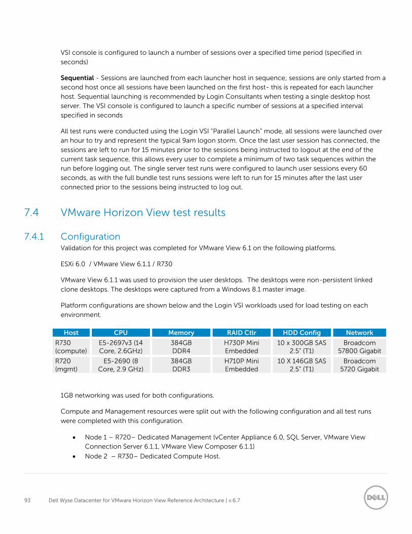
93 Dell Wyse Datacenter for VMware Horizon View Reference Architecture | v.6.7
VSI console is configured to launch a number of sessions over a specified time period (specified in
seconds)
Sequential - Sessions are launched from each launcher host in sequence; sessions are only started from a
second host once all sessions have been launched on the first host- this is repeated for each launcher
host. Sequential launching is recommended by Login Consultants when testing a single desktop host
server. The VSI console is configured to launch a specific number of sessions at a specified interval
specified in seconds
All test runs were conducted using the Login VSI “Parallel Launch” mode, all sessions were launched over
an hour to try and represent the typical 9am logon storm. Once the last user session has connected, the
sessions are left to run for 15 minutes prior to the sessions being instructed to logout at the end of the
current task sequence, this allows every user to complete a minimum of two task sequences within the
run before logging out. The single server test runs were configured to launch user sessions every 60
seconds, as with the full bundle test runs sessions were left to run for 15 minutes after the last user
connected prior to the sessions being instructed to log out.
7.4 VMware Horizon View test results
7.4.1 Configuration Validation for this project was completed for VMware View 6.1 on the following platforms.
ESXi 6.0 / VMware View 6.1.1 / R730
VMware View 6.1.1 was used to provision the user desktops. The desktops were non-persistent linked
clone desktops. The desktops were captured from a Windows 8.1 master image.
Platform configurations are shown below and the Login VSI workloads used for load testing on each
environment.
Host CPU Memory RAID Ctlr HDD Config Network
R730 (compute)
E5-2697v3 (14 Core, 2.6GHz)
384GB DDR4
H730P Mini Embedded
10 x 300GB SAS 2.5” (T1)
Broadcom 57800 Gigabit
R720 (mgmt)
E5-2690 (8 Core, 2.9 GHz)
384GB DDR3
H710P Mini Embedded
10 X 146GB SAS 2.5” (T1)
Broadcom 5720 Gigabit
1GB networking was used for both configurations.
Compute and Management resources were split out with the following configuration and all test runs
were completed with this configuration.
Node 1 – R720– Dedicated Management (vCenter Appliance 6.0, SQL Server, VMware View
Connection Server 6.1.1, VMware View Composer 6.1.1)
Node 2 – R730– Dedicated Compute Host.
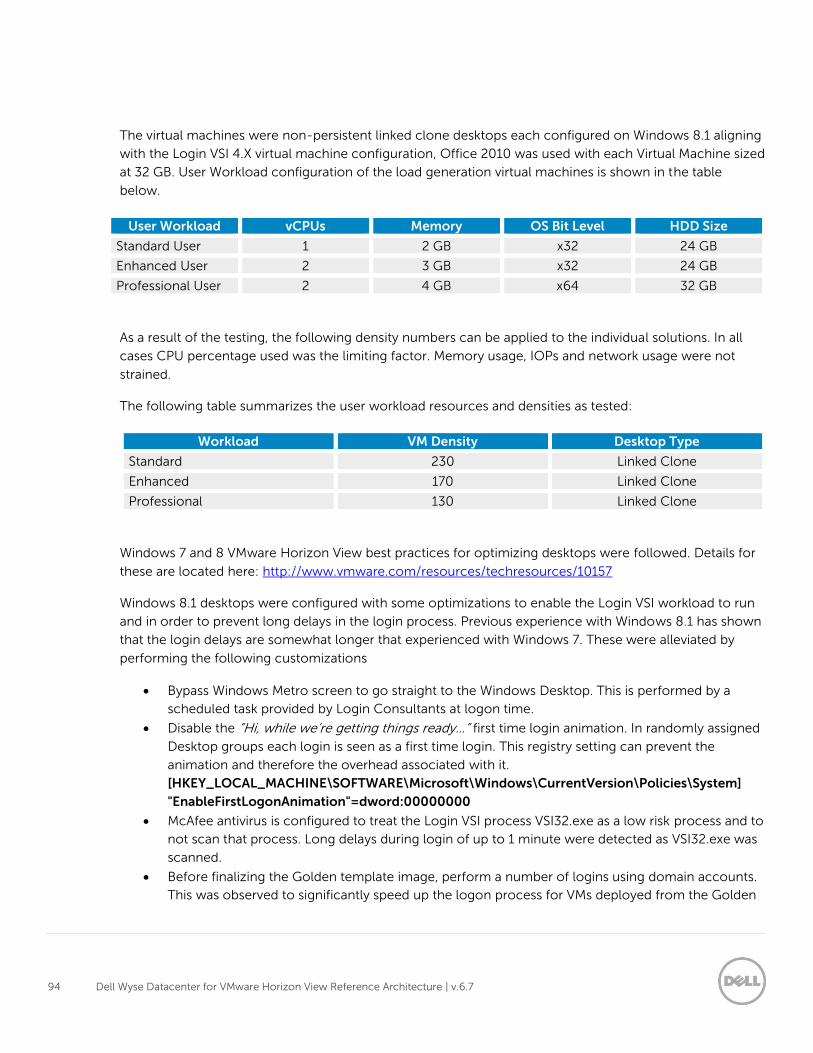
94 Dell Wyse Datacenter for VMware Horizon View Reference Architecture | v.6.7
The virtual machines were non-persistent linked clone desktops each configured on Windows 8.1 aligning
with the Login VSI 4.X virtual machine configuration, Office 2010 was used with each Virtual Machine sized
at 32 GB. User Workload configuration of the load generation virtual machines is shown in the table
below.
User Workload vCPUs Memory OS Bit Level HDD Size
Standard User 1 2 GB x32 24 GB
Enhanced User 2 3 GB x32 24 GB
Professional User 2 4 GB x64 32 GB
As a result of the testing, the following density numbers can be applied to the individual solutions. In all
cases CPU percentage used was the limiting factor. Memory usage, IOPs and network usage were not
strained.
The following table summarizes the user workload resources and densities as tested:
Workload VM Density Desktop Type
Standard 230 Linked Clone
Enhanced 170 Linked Clone
Professional 130 Linked Clone
Windows 7 and 8 VMware Horizon View best practices for optimizing desktops were followed. Details for
these are located here: http://www.vmware.com/resources/techresources/10157
Windows 8.1 desktops were configured with some optimizations to enable the Login VSI workload to run
and in order to prevent long delays in the login process. Previous experience with Windows 8.1 has shown
that the login delays are somewhat longer that experienced with Windows 7. These were alleviated by
performing the following customizations
Bypass Windows Metro screen to go straight to the Windows Desktop. This is performed by a
scheduled task provided by Login Consultants at logon time.
Disable the “Hi, while we’re getting things ready…” first time login animation. In randomly assigned
Desktop groups each login is seen as a first time login. This registry setting can prevent the
animation and therefore the overhead associated with it.
[HKEY_LOCAL_MACHINE\SOFTWARE\Microsoft\Windows\CurrentVersion\Policies\System]
"EnableFirstLogonAnimation"=dword:00000000
McAfee antivirus is configured to treat the Login VSI process VSI32.exe as a low risk process and to
not scan that process. Long delays during login of up to 1 minute were detected as VSI32.exe was
scanned.
Before finalizing the Golden template image, perform a number of logins using domain accounts.
This was observed to significantly speed up the logon process for VMs deployed from the Golden
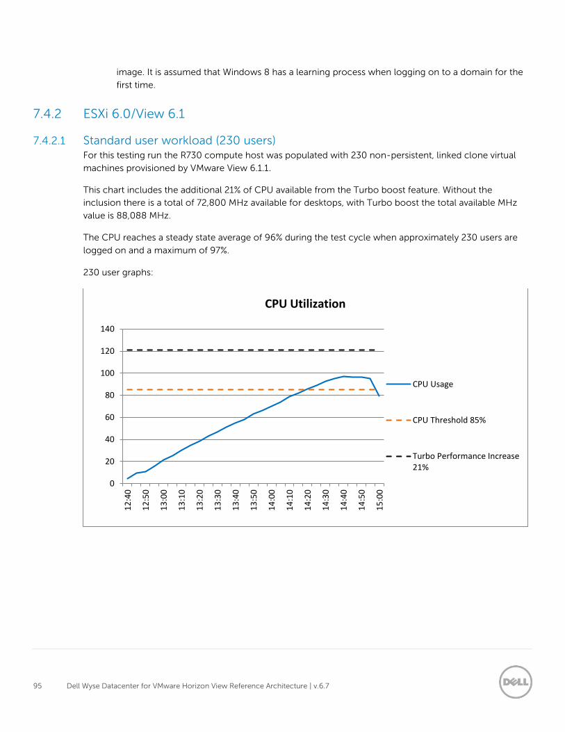
95 Dell Wyse Datacenter for VMware Horizon View Reference Architecture | v.6.7
image. It is assumed that Windows 8 has a learning process when logging on to a domain for the
first time.
7.4.2 ESXi 6.0/View 6.1
7.4.2.1 Standard user workload (230 users) For this testing run the R730 compute host was populated with 230 non-persistent, linked clone virtual
machines provisioned by VMware View 6.1.1.
This chart includes the additional 21% of CPU available from the Turbo boost feature. Without the
inclusion there is a total of 72,800 MHz available for desktops, with Turbo boost the total available MHz
value is 88,088 MHz.
The CPU reaches a steady state average of 96% during the test cycle when approximately 230 users are
logged on and a maximum of 97%.
230 user graphs:
0
20
40
60
80
100
120
140
12
:40
12
:50
13
:00
13
:10
13
:20
13
:30
13
:40
13
:50
14
:00
14
:10
14
:20
14
:30
14
:40
14
:50
15
:00
CPU Utilization
CPU Usage
CPU Threshold 85%
Turbo Performance Increase21%
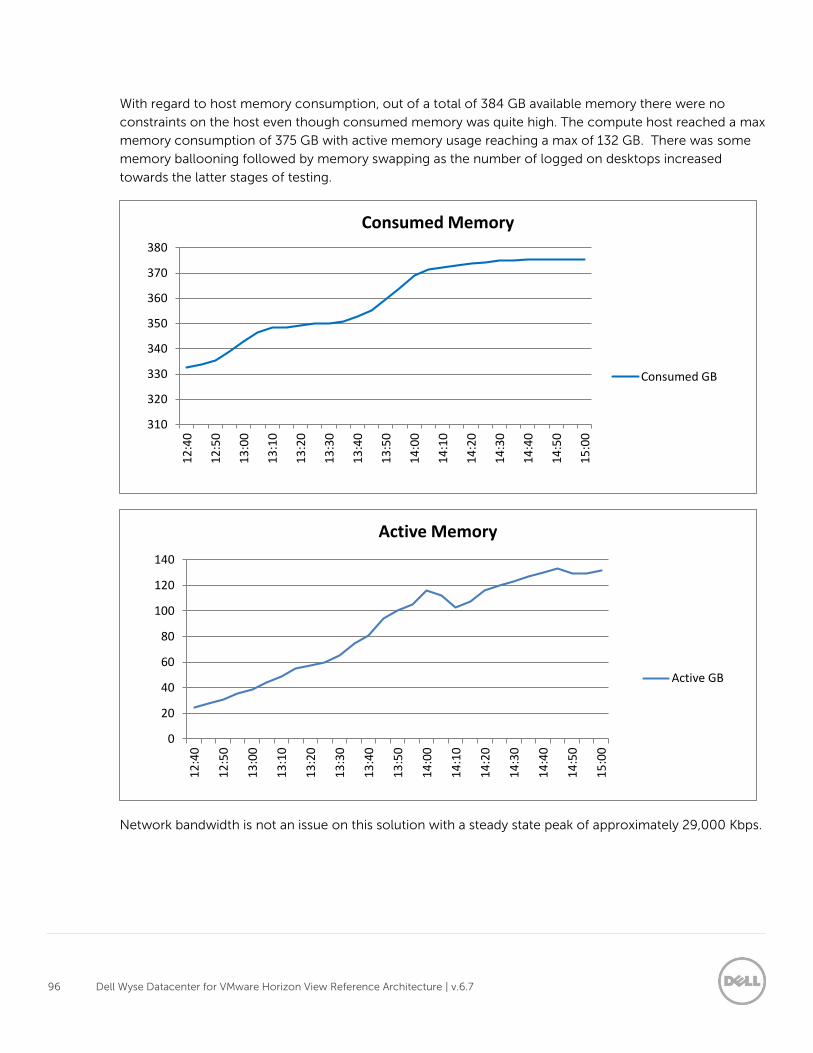
96 Dell Wyse Datacenter for VMware Horizon View Reference Architecture | v.6.7
With regard to host memory consumption, out of a total of 384 GB available memory there were no
constraints on the host even though consumed memory was quite high. The compute host reached a max
memory consumption of 375 GB with active memory usage reaching a max of 132 GB. There was some
memory ballooning followed by memory swapping as the number of logged on desktops increased
towards the latter stages of testing.
Network bandwidth is not an issue on this solution with a steady state peak of approximately 29,000 Kbps.
310
320
330
340
350
360
370
380
12
:40
12
:50
13
:00
13
:10
13
:20
13
:30
13
:40
13
:50
14
:00
14
:10
14
:20
14
:30
14
:40
14
:50
15
:00
Consumed Memory
Consumed GB
0
20
40
60
80
100
120
140
12
:40
12
:50
13
:00
13
:10
13
:20
13
:30
13
:40
13
:50
14
:00
14
:10
14
:20
14
:30
14
:40
14
:50
15
:00
Active Memory
Active GB
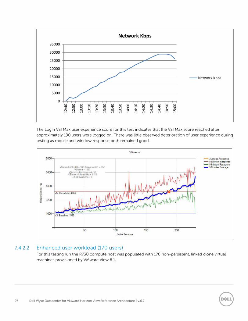
97 Dell Wyse Datacenter for VMware Horizon View Reference Architecture | v.6.7
The Login VSI Max user experience score for this test indicates that the VSI Max score reached after
approximately 190 users were logged on. There was little observed deterioration of user experience during
testing as mouse and window response both remained good.
7.4.2.2 Enhanced user workload (170 users) For this testing run the R730 compute host was populated with 170 non-persistent, linked clone virtual
machines provisioned by VMware View 6.1.
0
5000
10000
15000
20000
25000
30000
35000
12
:40
12
:50
13
:00
13
:10
13
:20
13
:30
13
:40
13
:50
14
:00
14
:10
14
:20
14
:30
14
:40
14
:50
15
:00
Network Kbps
Network Kbps
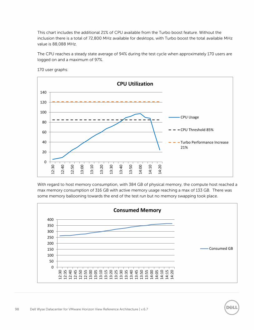
98 Dell Wyse Datacenter for VMware Horizon View Reference Architecture | v.6.7
This chart includes the additional 21% of CPU available from the Turbo boost feature. Without the
inclusion there is a total of 72,800 MHz available for desktops, with Turbo boost the total available MHz
value is 88,088 MHz.
The CPU reaches a steady state average of 94% during the test cycle when approximately 170 users are
logged on and a maximum of 97%.
170 user graphs:
With regard to host memory consumption, with 384 GB of physical memory, the compute host reached a
max memory consumption of 316 GB with active memory usage reaching a max of 133 GB. There was
some memory ballooning towards the end of the test run but no memory swapping took place.
0
20
40
60
80
100
120
140
12
:30
12
:40
12
:50
13
:00
13
:10
13
:20
13
:30
13
:40
13
:50
14
:00
14
:10
14
:20
CPU Utilization
CPU Usage
CPU Threshold 85%
Turbo Performance Increase21%
0
50
100
150
200
250
300
350
400
12
:30
12
:35
12
:40
12
:45
12
:50
12
:55
13
:00
13
:05
13
:10
13
:15
13
:20
13
:25
13
:30
13
:35
13
:40
13
:45
13
:50
13
:55
14
:00
14
:05
14
:10
14
:15
14
:20
Consumed Memory
Consumed GB
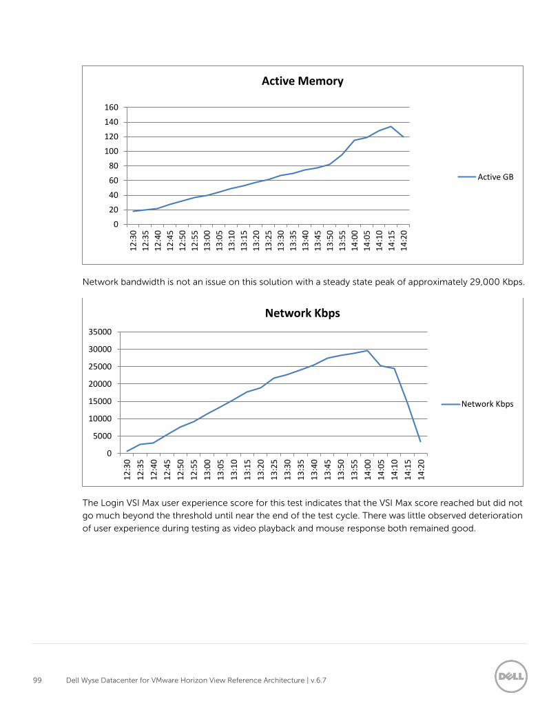
99 Dell Wyse Datacenter for VMware Horizon View Reference Architecture | v.6.7
Network bandwidth is not an issue on this solution with a steady state peak of approximately 29,000 Kbps.
The Login VSI Max user experience score for this test indicates that the VSI Max score reached but did not
go much beyond the threshold until near the end of the test cycle. There was little observed deterioration
of user experience during testing as video playback and mouse response both remained good.
0
20
40
60
80
100
120
140
160
12
:30
12
:35
12
:40
12
:45
12
:50
12
:55
13
:00
13
:05
13
:10
13
:15
13
:20
13
:25
13
:30
13
:35
13
:40
13
:45
13
:50
13
:55
14
:00
14
:05
14
:10
14
:15
14
:20
Active Memory
Active GB
0
5000
10000
15000
20000
25000
30000
35000
12
:30
12
:35
12
:40
12
:45
12
:50
12
:55
13
:00
13
:05
13
:10
13
:15
13
:20
13
:25
13
:30
13
:35
13
:40
13
:45
13
:50
13
:55
14
:00
14
:05
14
:10
14
:15
14
:20
Network Kbps
Network Kbps
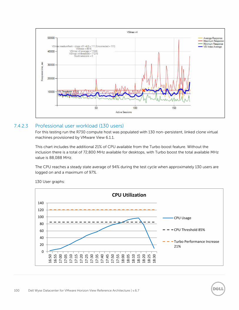
100 Dell Wyse Datacenter for VMware Horizon View Reference Architecture | v.6.7
7.4.2.3 Professional user workload (130 users) For this testing run the R730 compute host was populated with 130 non-persistent, linked clone virtual
machines provisioned by VMware View 6.1.1.
This chart includes the additional 21% of CPU available from the Turbo boost feature. Without the
inclusion there is a total of 72,800 MHz available for desktops, with Turbo boost the total available MHz
value is 88,088 MHz.
The CPU reaches a steady state average of 94% during the test cycle when approximately 130 users are
logged on and a maximum of 97%.
130 User graphs:
0
20
40
60
80
100
120
140
16
:50
16
:55
17
:00
17
:05
17
:10
17
:15
17
:20
17
:25
17
:30
17
:35
17
:40
17
:45
17
:50
17
:55
18
:00
18
:05
18
:10
18
:15
18
:20
18
:25
18
:30
CPU Utilization
CPU Usage
CPU Threshold 85%
Turbo Performance Increase21%
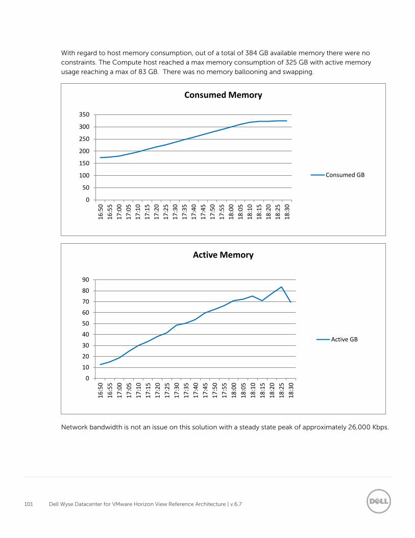
101 Dell Wyse Datacenter for VMware Horizon View Reference Architecture | v.6.7
With regard to host memory consumption, out of a total of 384 GB available memory there were no
constraints. The Compute host reached a max memory consumption of 325 GB with active memory
usage reaching a max of 83 GB. There was no memory ballooning and swapping.
Network bandwidth is not an issue on this solution with a steady state peak of approximately 26,000 Kbps.
0
50
100
150
200
250
300
350
16
:50
16
:55
17
:00
17
:05
17
:10
17
:15
17
:20
17
:25
17
:30
17
:35
17
:40
17
:45
17
:50
17
:55
18
:00
18
:05
18
:10
18
:15
18
:20
18
:25
18
:30
Consumed Memory
Consumed GB
0
10
20
30
40
50
60
70
80
90
16
:50
16
:55
17
:00
17
:05
17
:10
17
:15
17
:20
17
:25
17
:30
17
:35
17
:40
17
:45
17
:50
17
:55
18
:00
18
:05
18
:10
18
:15
18
:20
18
:25
18
:30
Active Memory
Active GB
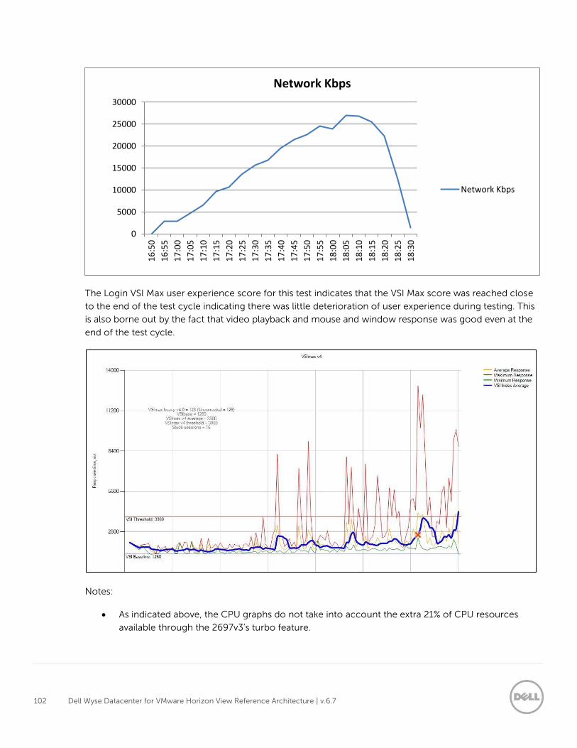
102 Dell Wyse Datacenter for VMware Horizon View Reference Architecture | v.6.7
The Login VSI Max user experience score for this test indicates that the VSI Max score was reached close
to the end of the test cycle indicating there was little deterioration of user experience during testing. This
is also borne out by the fact that video playback and mouse and window response was good even at the
end of the test cycle.
Notes:
As indicated above, the CPU graphs do not take into account the extra 21% of CPU resources
available through the 2697v3’s turbo feature.
0
5000
10000
15000
20000
25000
30000
16
:50
16
:55
17
:00
17
:05
17
:10
17
:15
17
:20
17
:25
17
:30
17
:35
17
:40
17
:45
17
:50
17
:55
18
:00
18
:05
18
:10
18
:15
18
:20
18
:25
18
:30
Network Kbps
Network Kbps
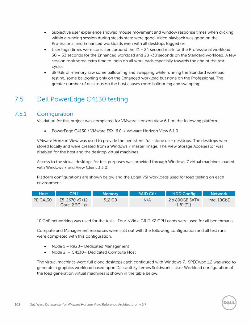
103 Dell Wyse Datacenter for VMware Horizon View Reference Architecture | v.6.7
Subjective user experience showed mouse movement and window response times when clicking
within a running session during steady state were good. Video playback was good on the
Professional and Enhanced workloads even with all desktops logged on.
User login times were consistent around the 21 - 24 second mark for the Professional workload,
30 – 33 seconds for the Enhanced workload and 28 -30 seconds on the Standard workload. A few
session took some extra time to login on all workloads especially towards the end of the test
cycles.
384GB of memory saw some ballooning and swapping while running the Standard workload
testing, some ballooning only on the Enhanced workload but none on the Professional. The
greater number of desktops on the host causes more ballooning and swapping.
7.5 Dell PowerEdge C4130 testing
7.5.1 Configuration Validation for this project was completed for VMware Horizon View 6.1 on the following platform:
PowerEdge C4130 / VMware ESXi 6.0 / VMware Horizon View 6.1.0
VMware Horizon View was used to provide the persistent, full-clone user desktops. The desktops were
stored locally and were created from a Windows 7 master image. The View Storage Accelerator was
disabled for the host and the desktop virtual machines.
Access to the virtual desktops for test purposes was provided through Windows 7 virtual machines loaded
with Windows 7 and View Client 3.3.0.
Platform configurations are shown below and the Login VSI workloads used for load testing on each
environment.
Host CPU Memory RAID Ctlr HDD Config Network
PE C4130 E5-2670 v3 (12 Core, 2.3GHz)
512 GB N/A 2 x 800GB SATA 1.8” (T1)
Intel 10GbE
10 GbE networking was used for the tests. Four NVidia GRID K2 GPU cards were used for all benchmarks.
Compute and Management resources were split out with the following configuration and all test runs
were completed with this configuration.
Node 1 – R920– Dedicated Management
Node 2 – C4130– Dedicated Compute Host
The virtual machines were full clone desktops each configured with Windows 7. SPECwpc 1.2 was used to
generate a graphics workload based upon Dassault Systemes Solidworks. User Workload configuration of
the load generation virtual machines is shown in the table below.
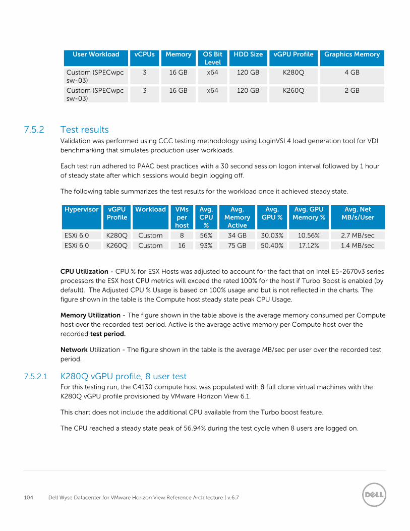
104 Dell Wyse Datacenter for VMware Horizon View Reference Architecture | v.6.7
User Workload vCPUs Memory OS Bit Level
HDD Size vGPU Profile Graphics Memory
Custom (SPECwpc sw-03)
3 16 GB x64 120 GB K280Q 4 GB
Custom (SPECwpc sw-03)
3 16 GB x64 120 GB K260Q 2 GB
7.5.2 Test results Validation was performed using CCC testing methodology using LoginVSI 4 load generation tool for VDI
benchmarking that simulates production user workloads.
Each test run adhered to PAAC best practices with a 30 second session logon interval followed by 1 hour
of steady state after which sessions would begin logging off.
The following table summarizes the test results for the workload once it achieved steady state.
Hypervisor vGPU Profile
Workload VMs per
host
Avg. CPU
%
Avg. Memory
Active
Avg. GPU %
Avg. GPU Memory %
Avg. Net MB/s/User
ESXi 6.0 K280Q Custom 8 56% 34 GB 30.03% 10.56% 2.7 MB/sec
ESXi 6.0 K260Q Custom 16 93% 75 GB 50.40% 17.12% 1.4 MB/sec
CPU Utilization - CPU % for ESX Hosts was adjusted to account for the fact that on Intel E5-2670v3 series
processors the ESX host CPU metrics will exceed the rated 100% for the host if Turbo Boost is enabled (by
default). The Adjusted CPU % Usage is based on 100% usage and but is not reflected in the charts. The
figure shown in the table is the Compute host steady state peak CPU Usage.
Memory Utilization - The figure shown in the table above is the average memory consumed per Compute
host over the recorded test period. Active is the average active memory per Compute host over the
recorded test period.
Network Utilization - The figure shown in the table is the average MB/sec per user over the recorded test
period.
7.5.2.1 K280Q vGPU profile, 8 user test For this testing run, the C4130 compute host was populated with 8 full clone virtual machines with the
K280Q vGPU profile provisioned by VMware Horizon View 6.1.
This chart does not include the additional CPU available from the Turbo boost feature.
The CPU reached a steady state peak of 56.94% during the test cycle when 8 users are logged on.
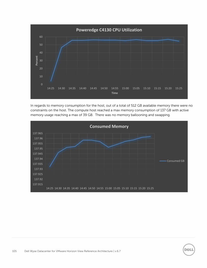
105 Dell Wyse Datacenter for VMware Horizon View Reference Architecture | v.6.7
In regards to memory consumption for the host, out of a total of 512 GB available memory there were no
constraints on the host. The compute host reached a max memory consumption of 137 GB with active
memory usage reaching a max of 39 GB. There was no memory ballooning and swapping.
0
10
20
30
40
50
60
14:25 14:30 14:35 14:40 14:45 14:50 14:55 15:00 15:05 15:10 15:15 15:20 15:25
Pe
rce
nt
Time
Poweredge C4130 CPU Utilization
137.915
137.92
137.925
137.93
137.935
137.94
137.945
137.95
137.955
137.96
137.965
14:25 14:30 14:35 14:40 14:45 14:50 14:55 15:00 15:05 15:10 15:15 15:20 15:25
Consumed Memory
Consumed GB
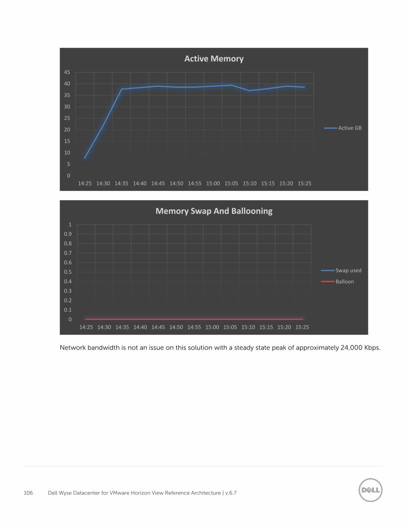
106 Dell Wyse Datacenter for VMware Horizon View Reference Architecture | v.6.7
Network bandwidth is not an issue on this solution with a steady state peak of approximately 24,000 Kbps.
0
5
10
15
20
25
30
35
40
45
14:25 14:30 14:35 14:40 14:45 14:50 14:55 15:00 15:05 15:10 15:15 15:20 15:25
Active Memory
Active GB
0
0.1
0.2
0.3
0.4
0.5
0.6
0.7
0.8
0.9
1
14:25 14:30 14:35 14:40 14:45 14:50 14:55 15:00 15:05 15:10 15:15 15:20 15:25
Memory Swap And Ballooning
Swap used
Balloon
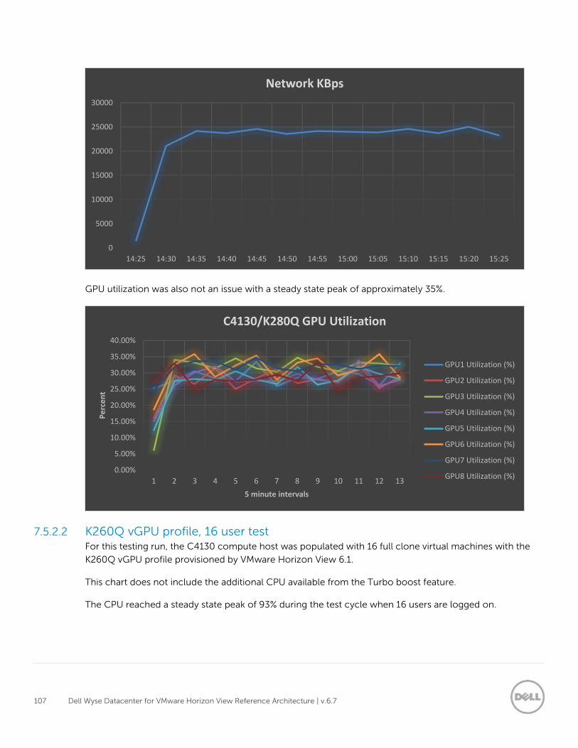
107 Dell Wyse Datacenter for VMware Horizon View Reference Architecture | v.6.7
GPU utilization was also not an issue with a steady state peak of approximately 35%.
7.5.2.2 K260Q vGPU profile, 16 user test For this testing run, the C4130 compute host was populated with 16 full clone virtual machines with the
K260Q vGPU profile provisioned by VMware Horizon View 6.1.
This chart does not include the additional CPU available from the Turbo boost feature.
The CPU reached a steady state peak of 93% during the test cycle when 16 users are logged on.
0
5000
10000
15000
20000
25000
30000
14:25 14:30 14:35 14:40 14:45 14:50 14:55 15:00 15:05 15:10 15:15 15:20 15:25
Network KBps
0.00%
5.00%
10.00%
15.00%
20.00%
25.00%
30.00%
35.00%
40.00%
1 2 3 4 5 6 7 8 9 10 11 12 13
Pe
rce
nt
5 minute intervals
C4130/K280Q GPU Utilization
GPU1 Utilization (%)
GPU2 Utilization (%)
GPU3 Utilization (%)
GPU4 Utilization (%)
GPU5 Utilization (%)
GPU6 Utilization (%)
GPU7 Utilization (%)
GPU8 Utilization (%)
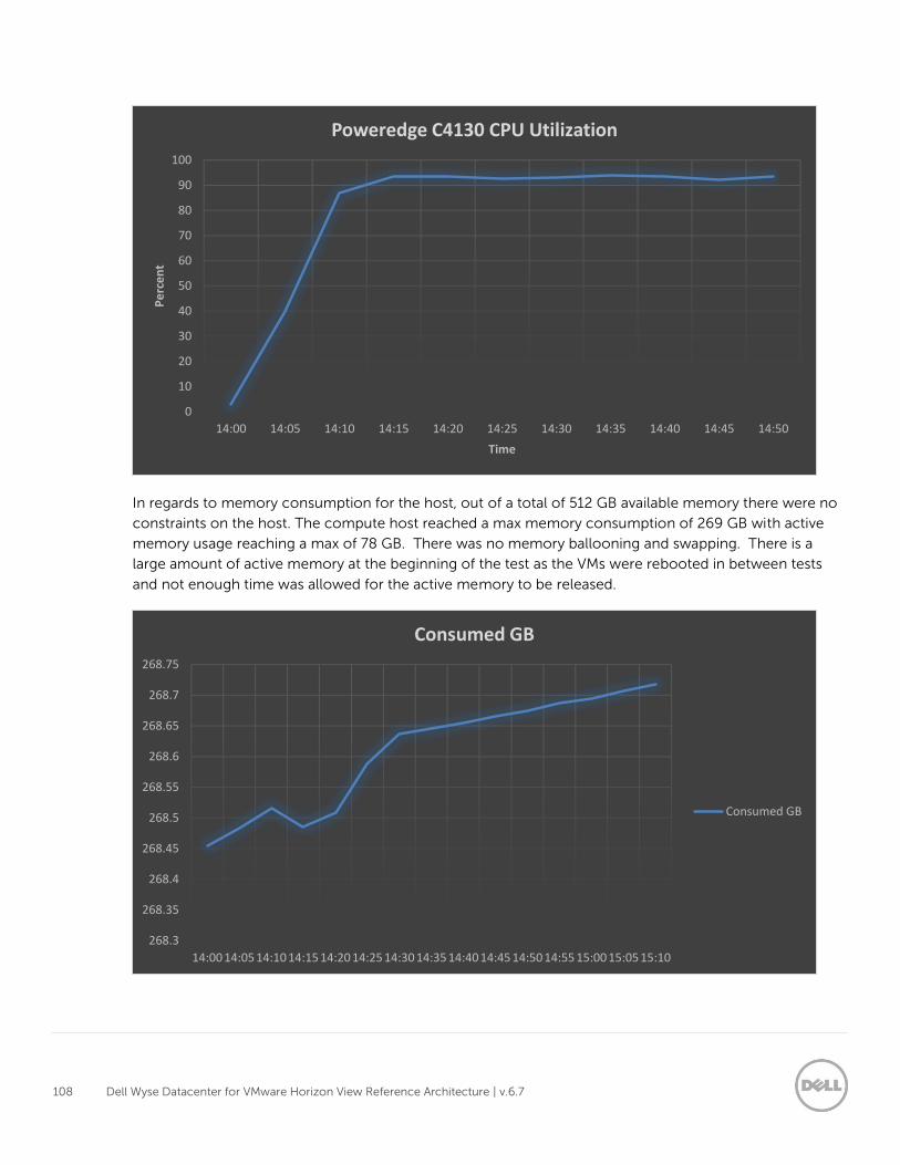
108 Dell Wyse Datacenter for VMware Horizon View Reference Architecture | v.6.7
In regards to memory consumption for the host, out of a total of 512 GB available memory there were no
constraints on the host. The compute host reached a max memory consumption of 269 GB with active
memory usage reaching a max of 78 GB. There was no memory ballooning and swapping. There is a
large amount of active memory at the beginning of the test as the VMs were rebooted in between tests
and not enough time was allowed for the active memory to be released.
0
10
20
30
40
50
60
70
80
90
100
14:00 14:05 14:10 14:15 14:20 14:25 14:30 14:35 14:40 14:45 14:50
Pe
rce
nt
Time
Poweredge C4130 CPU Utilization
268.3
268.35
268.4
268.45
268.5
268.55
268.6
268.65
268.7
268.75
14:00 14:05 14:10 14:15 14:20 14:25 14:30 14:35 14:40 14:45 14:50 14:55 15:00 15:05 15:10
Consumed GB
Consumed GB
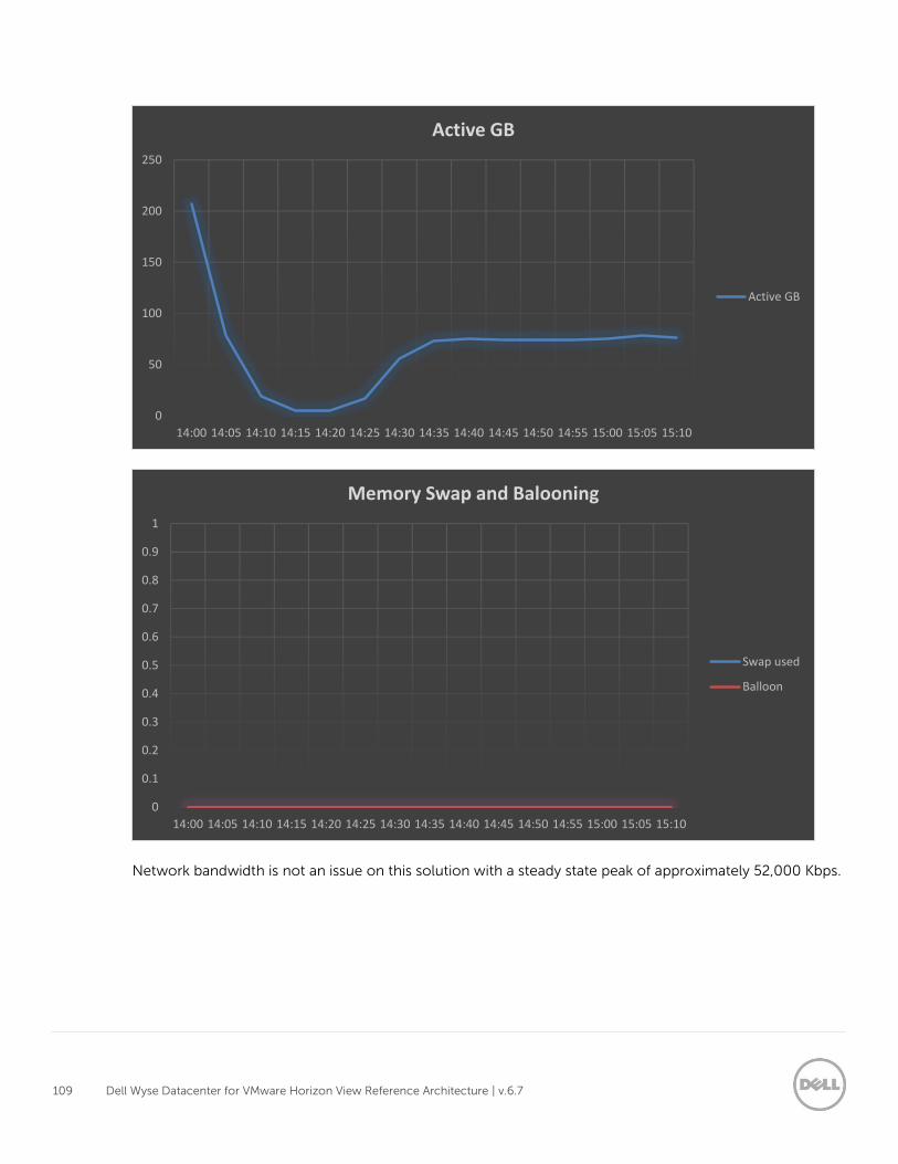
109 Dell Wyse Datacenter for VMware Horizon View Reference Architecture | v.6.7
Network bandwidth is not an issue on this solution with a steady state peak of approximately 52,000 Kbps.
0
50
100
150
200
250
14:00 14:05 14:10 14:15 14:20 14:25 14:30 14:35 14:40 14:45 14:50 14:55 15:00 15:05 15:10
Active GB
Active GB
0
0.1
0.2
0.3
0.4
0.5
0.6
0.7
0.8
0.9
1
14:00 14:05 14:10 14:15 14:20 14:25 14:30 14:35 14:40 14:45 14:50 14:55 15:00 15:05 15:10
Memory Swap and Balooning
Swap used
Balloon
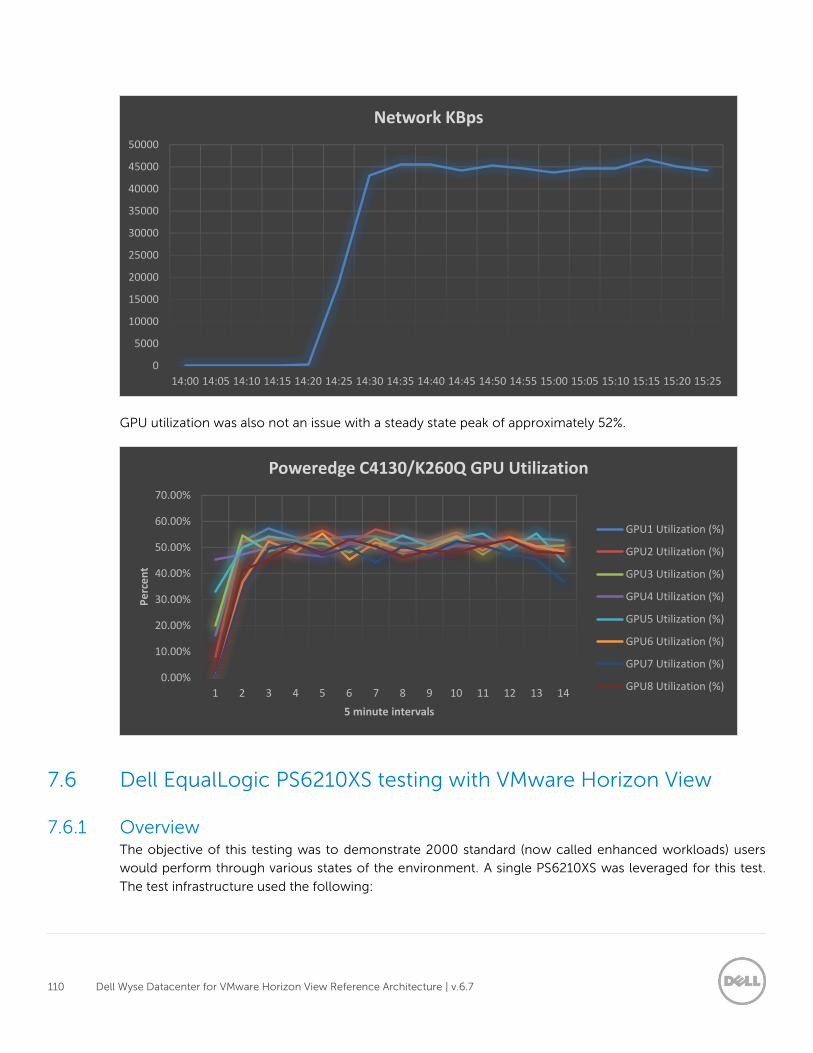
110 Dell Wyse Datacenter for VMware Horizon View Reference Architecture | v.6.7
GPU utilization was also not an issue with a steady state peak of approximately 52%.
7.6 Dell EqualLogic PS6210XS testing with VMware Horizon View
7.6.1 Overview The objective of this testing was to demonstrate 2000 standard (now called enhanced workloads) users
would perform through various states of the environment. A single PS6210XS was leveraged for this test.
The test infrastructure used the following:
0
5000
10000
15000
20000
25000
30000
35000
40000
45000
50000
14:00 14:05 14:10 14:15 14:20 14:25 14:30 14:35 14:40 14:45 14:50 14:55 15:00 15:05 15:10 15:15 15:20 15:25
Network KBps
0.00%
10.00%
20.00%
30.00%
40.00%
50.00%
60.00%
70.00%
1 2 3 4 5 6 7 8 9 10 11 12 13 14
Pe
rce
nt
5 minute intervals
Poweredge C4130/K260Q GPU Utilization
GPU1 Utilization (%)
GPU2 Utilization (%)
GPU3 Utilization (%)
GPU4 Utilization (%)
GPU5 Utilization (%)
GPU6 Utilization (%)
GPU7 Utilization (%)
GPU8 Utilization (%)
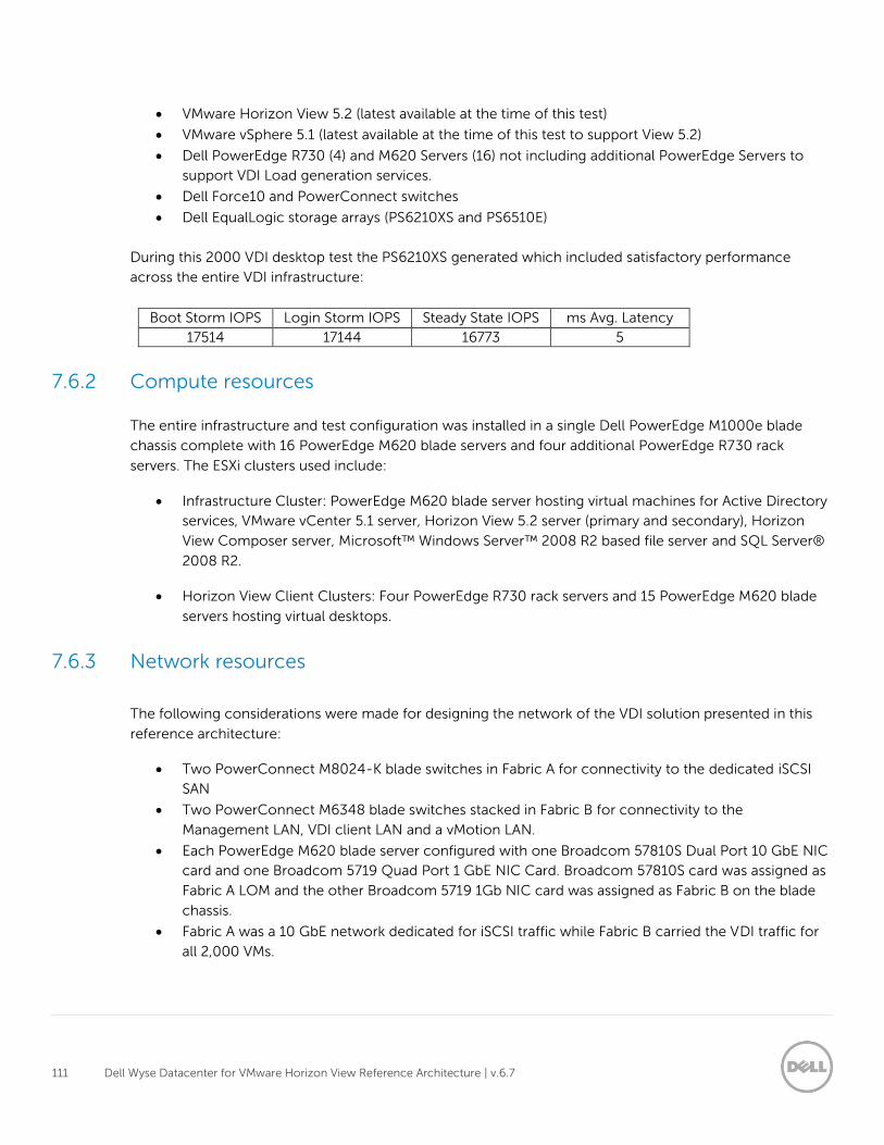
111 Dell Wyse Datacenter for VMware Horizon View Reference Architecture | v.6.7
VMware Horizon View 5.2 (latest available at the time of this test)
VMware vSphere 5.1 (latest available at the time of this test to support View 5.2)
Dell PowerEdge R730 (4) and M620 Servers (16) not including additional PowerEdge Servers to
support VDI Load generation services.
Dell Force10 and PowerConnect switches
Dell EqualLogic storage arrays (PS6210XS and PS6510E)
During this 2000 VDI desktop test the PS6210XS generated which included satisfactory performance
across the entire VDI infrastructure:
Boot Storm IOPS Login Storm IOPS Steady State IOPS ms Avg. Latency
17514 17144 16773 5
7.6.2 Compute resources
The entire infrastructure and test configuration was installed in a single Dell PowerEdge M1000e blade
chassis complete with 16 PowerEdge M620 blade servers and four additional PowerEdge R730 rack
servers. The ESXi clusters used include:
Infrastructure Cluster: PowerEdge M620 blade server hosting virtual machines for Active Directory
services, VMware vCenter 5.1 server, Horizon View 5.2 server (primary and secondary), Horizon
View Composer server, Microsoft™ Windows Server™ 2008 R2 based file server and SQL Server®
2008 R2.
Horizon View Client Clusters: Four PowerEdge R730 rack servers and 15 PowerEdge M620 blade
servers hosting virtual desktops.
7.6.3 Network resources
The following considerations were made for designing the network of the VDI solution presented in this
reference architecture:
Two PowerConnect M8024-K blade switches in Fabric A for connectivity to the dedicated iSCSI
SAN
Two PowerConnect M6348 blade switches stacked in Fabric B for connectivity to the
Management LAN, VDI client LAN and a vMotion LAN.
Each PowerEdge M620 blade server configured with one Broadcom 57810S Dual Port 10 GbE NIC
card and one Broadcom 5719 Quad Port 1 GbE NIC Card. Broadcom 57810S card was assigned as
Fabric A LOM and the other Broadcom 5719 1Gb NIC card was assigned as Fabric B on the blade
chassis.
Fabric A was a 10 GbE network dedicated for iSCSI traffic while Fabric B carried the VDI traffic for
all 2,000 VMs.
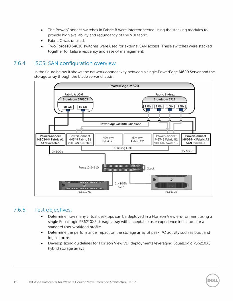
112 Dell Wyse Datacenter for VMware Horizon View Reference Architecture | v.6.7
The PowerConnect switches in Fabric B were interconnected using the stacking modules to
provide high availability and redundancy of the VDI fabric.
Fabric C was unused.
Two Force10 S4810 switches were used for external SAN access. These switches were stacked
together for failure resiliency and ease of management.
7.6.4 iSCSI SAN configuration overview
In the figure below it shows the network connectivity between a single PowerEdge M620 Server and the storage array though the blade server chassis:
7.6.5 Test objectives: Determine how many virtual desktops can be deployed in a Horizon View environment using a
single EqualLogic PS6210XS storage array with acceptable user experience indicators for a
standard user workload profile.
Determine the performance impact on the storage array of peak I/O activity such as boot and
login storms
Develop sizing guidelines for Horizon View VDI deployments leveraging EqualLogic PS6210XS
hybrid storage arrays
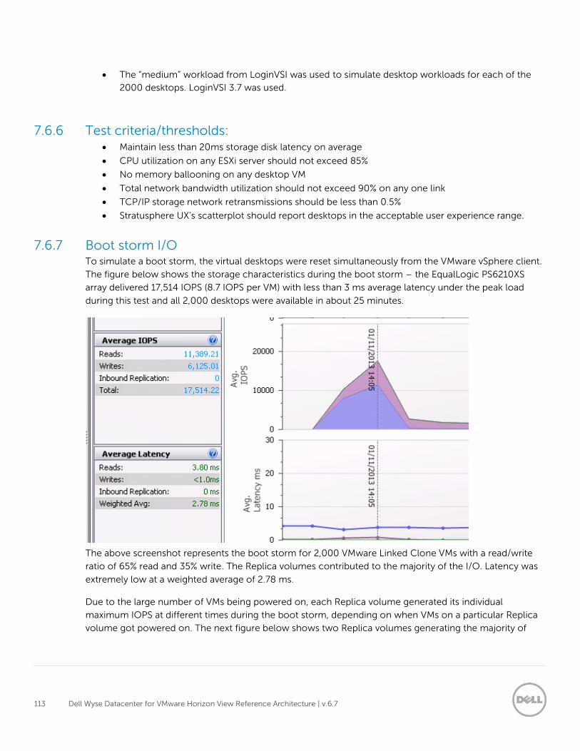
113 Dell Wyse Datacenter for VMware Horizon View Reference Architecture | v.6.7
The “medium” workload from LoginVSI was used to simulate desktop workloads for each of the
2000 desktops. LoginVSI 3.7 was used.
7.6.6 Test criteria/thresholds: Maintain less than 20ms storage disk latency on average
CPU utilization on any ESXi server should not exceed 85%
No memory ballooning on any desktop VM
Total network bandwidth utilization should not exceed 90% on any one link
TCP/IP storage network retransmissions should be less than 0.5%
Stratusphere UX’s scatterplot should report desktops in the acceptable user experience range.
7.6.7 Boot storm I/O To simulate a boot storm, the virtual desktops were reset simultaneously from the VMware vSphere client.
The figure below shows the storage characteristics during the boot storm – the EqualLogic PS6210XS
array delivered 17,514 IOPS (8.7 IOPS per VM) with less than 3 ms average latency under the peak load
during this test and all 2,000 desktops were available in about 25 minutes.
The above screenshot represents the boot storm for 2,000 VMware Linked Clone VMs with a read/write
ratio of 65% read and 35% write. The Replica volumes contributed to the majority of the I/O. Latency was
extremely low at a weighted average of 2.78 ms.
Due to the large number of VMs being powered on, each Replica volume generated its individual
maximum IOPS at different times during the boot storm, depending on when VMs on a particular Replica
volume got powered on. The next figure below shows two Replica volumes generating the majority of
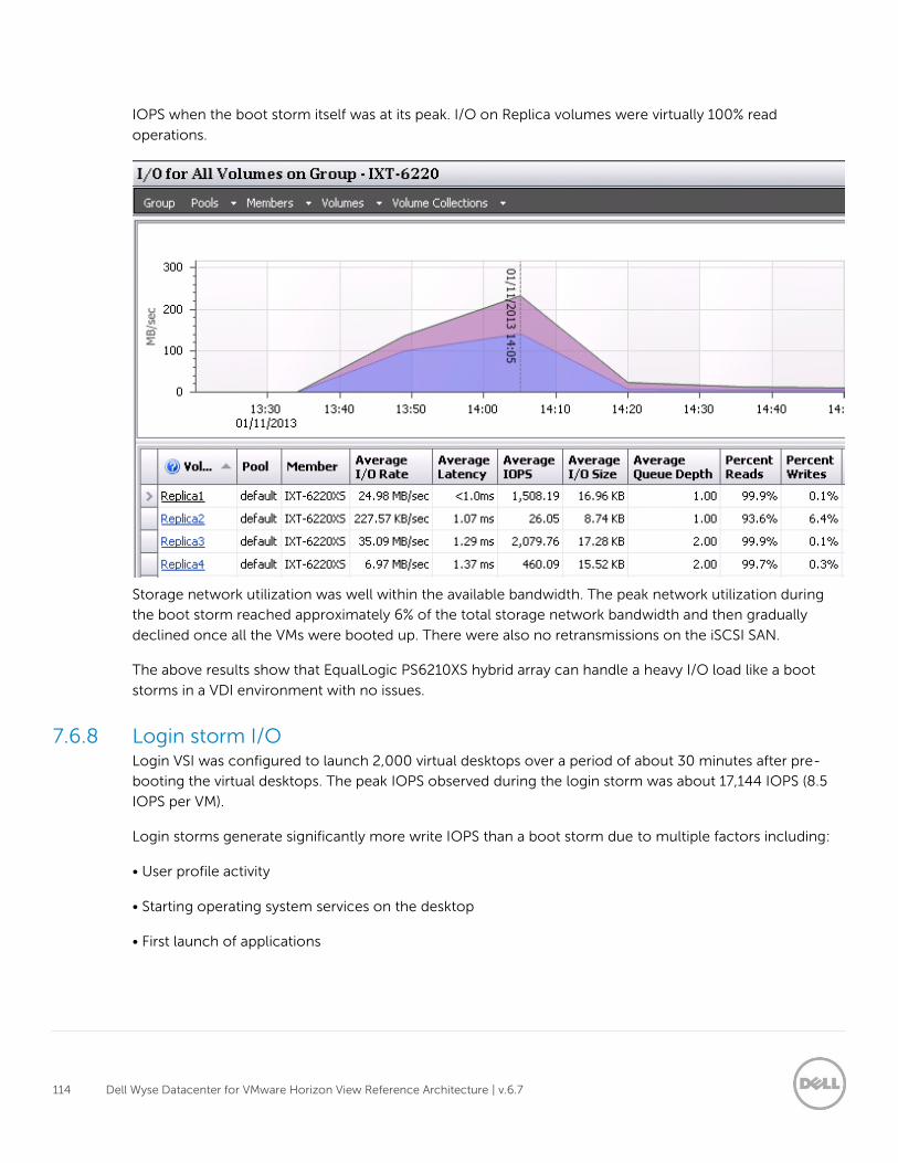
114 Dell Wyse Datacenter for VMware Horizon View Reference Architecture | v.6.7
IOPS when the boot storm itself was at its peak. I/O on Replica volumes were virtually 100% read
operations.
Storage network utilization was well within the available bandwidth. The peak network utilization during
the boot storm reached approximately 6% of the total storage network bandwidth and then gradually
declined once all the VMs were booted up. There were also no retransmissions on the iSCSI SAN.
The above results show that EqualLogic PS6210XS hybrid array can handle a heavy I/O load like a boot
storms in a VDI environment with no issues.
7.6.8 Login storm I/O Login VSI was configured to launch 2,000 virtual desktops over a period of about 30 minutes after pre-
booting the virtual desktops. The peak IOPS observed during the login storm was about 17,144 IOPS (8.5
IOPS per VM).
Login storms generate significantly more write IOPS than a boot storm due to multiple factors including:
• User profile activity
• Starting operating system services on the desktop
• First launch of applications
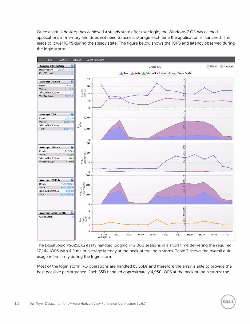
115 Dell Wyse Datacenter for VMware Horizon View Reference Architecture | v.6.7
Once a virtual desktop has achieved a steady state after user login, the Windows 7 OS has cached
applications in memory and does not need to access storage each time the application is launched. This
leads to lower IOPS during the steady state. The figure below shows the IOPS and latency observed during
the login storm.
The EqualLogic PS6210XS easily handled logging in 2,000 sessions in a short time delivering the required
17,144 IOPS with 4.2 ms of average latency at the peak of the login storm. Table 7 shows the overall disk
usage in the array during the login storm.
Most of the login storm I/O operations are handled by SSDs and therefore the array is able to provide the
best possible performance. Each SSD handled approximately 4,950 IOPS at the peak of login storm; the
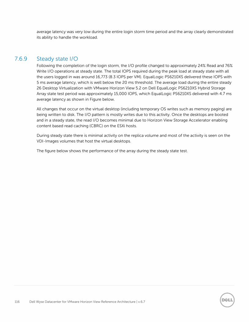
116 Dell Wyse Datacenter for VMware Horizon View Reference Architecture | v.6.7
average latency was very low during the entire login storm time period and the array clearly demonstrated
its ability to handle the workload.
7.6.9 Steady state I/O Following the completion of the login storm, the I/O profile changed to approximately 24% Read and 76%
Write I/O operations at steady state. The total IOPS required during the peak load at steady state with all
the users logged in was around 16,773 (8.3 IOPS per VM). EqualLogic PS6210XS delivered these IOPS with
5 ms average latency, which is well below the 20 ms threshold. The average load during the entire steady
26 Desktop Virtualization with VMware Horizon View 5.2 on Dell EqualLogic PS6210XS Hybrid Storage
Array state test period was approximately 15,000 IOPS, which EqualLogic PS6210XS delivered with 4.7 ms
average latency as shown in Figure below.
All changes that occur on the virtual desktop (including temporary OS writes such as memory paging) are
being written to disk. The I/O pattern is mostly writes due to this activity. Once the desktops are booted
and in a steady state, the read I/O becomes minimal due to Horizon View Storage Accelerator enabling
content based read caching (CBRC) on the ESXi hosts.
During steady state there is minimal activity on the replica volume and most of the activity is seen on the
VDI-Images volumes that host the virtual desktops.
The figure below shows the performance of the array during the steady state test.
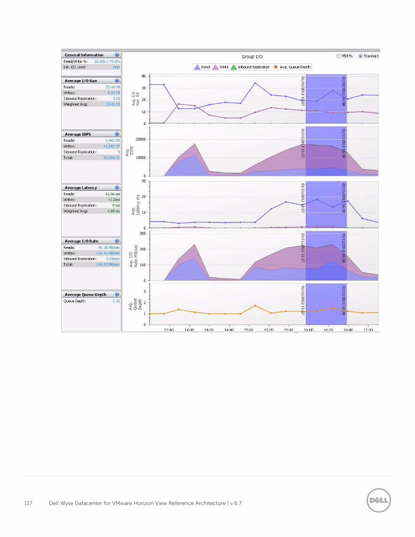
117 Dell Wyse Datacenter for VMware Horizon View Reference Architecture | v.6.7
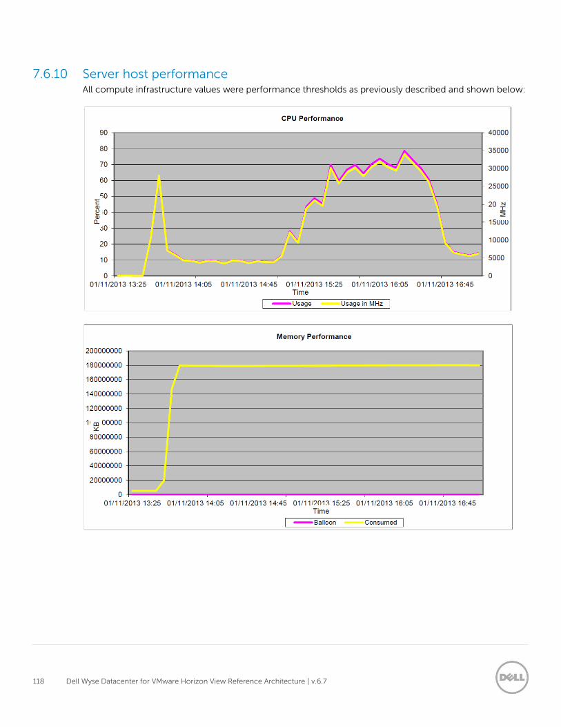
118 Dell Wyse Datacenter for VMware Horizon View Reference Architecture | v.6.7
7.6.10 Server host performance All compute infrastructure values were performance thresholds as previously described and shown below:
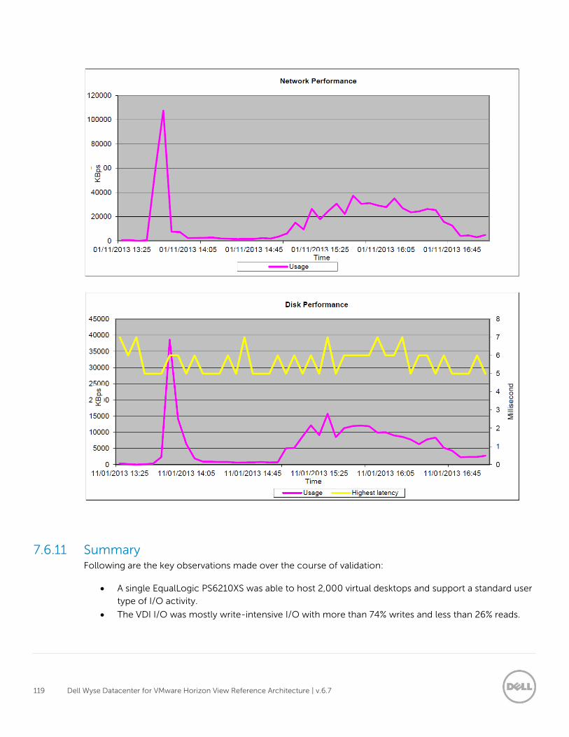
119 Dell Wyse Datacenter for VMware Horizon View Reference Architecture | v.6.7
7.6.11 Summary Following are the key observations made over the course of validation:
A single EqualLogic PS6210XS was able to host 2,000 virtual desktops and support a standard user
type of I/O activity.
The VDI I/O was mostly write-intensive I/O with more than 74% writes and less than 26% reads.
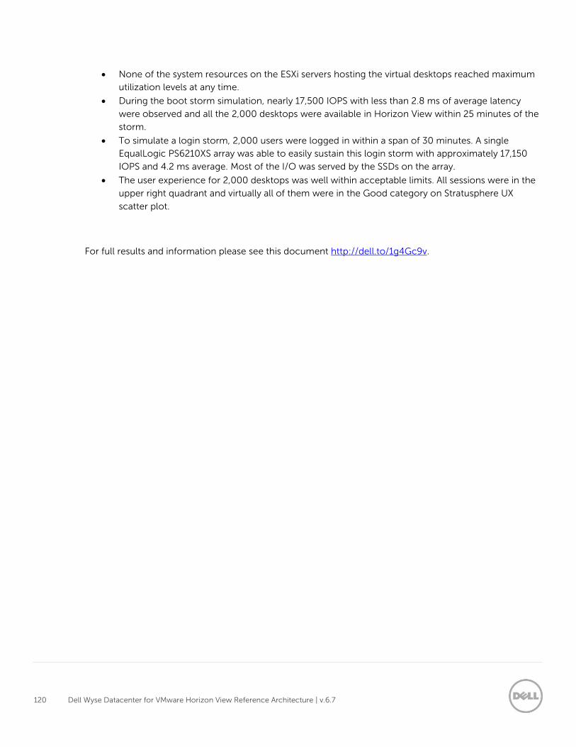
120 Dell Wyse Datacenter for VMware Horizon View Reference Architecture | v.6.7
None of the system resources on the ESXi servers hosting the virtual desktops reached maximum
utilization levels at any time.
During the boot storm simulation, nearly 17,500 IOPS with less than 2.8 ms of average latency
were observed and all the 2,000 desktops were available in Horizon View within 25 minutes of the
storm.
To simulate a login storm, 2,000 users were logged in within a span of 30 minutes. A single
EqualLogic PS6210XS array was able to easily sustain this login storm with approximately 17,150
IOPS and 4.2 ms average. Most of the I/O was served by the SSDs on the array.
The user experience for 2,000 desktops was well within acceptable limits. All sessions were in the
upper right quadrant and virtually all of them were in the Good category on Stratusphere UX
scatter plot.
For full results and information please see this document http://dell.to/1g4Gc9v.
121 Dell Wyse Datacenter for VMware Horizon View Reference Architecture | v.6.7
Acknowledgements
Thanks to the Darin Schmitz and Damon Zaylskie of the Dell Compellent MSV Solutions team for providing
expertise and validation of the Dell Wyse Datacenter Compellent Tier 1 array.
Thanks to Paul Wynne and the Dell Wyse Solutions Ingredients Extended Team for their expertise and
continued support validating VDI architectures and Tier 1 storage.
Thanks to Sujit Somandepalli and Chhandomay Mandal of Storage Engineering and Storage Technical
Marketing respectively for Storage contributions.
Thanks to John Kelly of the Dell Wyse Solutions Engineering team for his expertise and guidance in the
Dell Wyse Datacenter PAAC process.
About the authors
Gus Chavira is the Senior Principal Engineering Architect for VMware Horizon based solutions at Dell. Gus
has extensive experience and expertise on the VMware solutions software stacks as well as in Enterprise
virtualization, storage and enterprise data center design. Gus has worked in capacities of Sys Admin, DBA,
Network and Storage Admin, Virtualization Practice Architect, Enterprise and Solutions Architect. In
addition, Gus carries a B.S. in Computer Science
Peter Fine is the Senior Principal Engineering Architect for VDI-based solutions at Dell. Peter has extensive
experience and expertise on the broader Microsoft, Citrix and VMware solutions software stacks as well as
in enterprise virtualization, storage, networking and enterprise data center design.
Andrew McDaniel is the Solutions Development Manager for VMware solutions at Dell, managing the
development and delivery of enterprise-class desktop virtualization solutions based on Dell Data center
components and core virtualization platforms.
Nicholas Busick is a Senior Solutions Engineer with Dell Wyse Solutions Engineering building, testing,
validating and optimizing enterprise VDI stacks.
Darpan Patel is a Senior Solutions Engineer with Dell Wyse Solutions Engineering with extensive
experience in validating, building and optimizing enterprise class VDI solutions on Microsoft (Hyper-V),
VMware (View) and Citrix (XenDesktop). Darpan has a master’s degree in Information Systems from Pace
University in New York and is VCP5-DCV certified. (VMware Certified Professional 5 – Data Center
Virtualization).
David Hulama is a Senior Technical Marketing Advisor for VMware Horizon View solutions at Dell. David
has a broad technical background in a variety of technical areas and expertise in enterprise-class
virtualization solutions.