Embed Size (px)
Citation preview
A Dell Reference Architecture
Dell VMware vSAN Ready Nodes for Citrix XenDesktop.
A Reference Architecture document for the design, configuration and implementation of a vSAN Ready Node environment with Citrix XenDesktop.
Dell Engineering July 2017
2 Dell VMware vSAN Ready Nodes for Citrix XenDesktop. | July 2017
Revisions
Date Description
July 2017 Initial release
THIS WHITE PAPER IS FOR INFORMATIONAL PURPOSES ONLY, AND MAY CONTAIN TYPOGRAPHICAL ERRORS AND TECHNICAL
INACCURACIES. THE CONTENT IS PROVIDED AS IS, WITHOUT EXPRESS OR IMPLIED WARRANTIES OF ANY KIND.
Copyright © 2016-2017 Dell Inc. All rights reserved. Dell and the Dell logo are trademarks of Dell Inc. in the United States and/or other jurisdictions. All
other marks and names mentioned herein may be trademarks of their respective companies.
3 Dell VMware vSAN Ready Nodes for Citrix XenDesktop. | July 2017
Table of contents Revisions............................................................................................................................................................................. 2
1 Introduction ................................................................................................................................................................... 6
1.1 Purpose .............................................................................................................................................................. 6
1.2 Scope .................................................................................................................................................................. 6
1.3 What’s new ......................................................................................................................................................... 6
2 Solution architecture overview ..................................................................................................................................... 7
2.1 Introduction ......................................................................................................................................................... 7
2.2 What is a vSAN Ready Node (VSRN)? .............................................................................................................. 7
2.3 Physical architecture overview ........................................................................................................................... 8
2.4 Solution layers .................................................................................................................................................... 8
2.4.1 Networking .......................................................................................................................................................... 8
2.4.2 vSAN Ready Node Host ..................................................................................................................................... 9
2.4.3 Storage (vSAN) ................................................................................................................................................. 10
2.5 vSAN Ready Node............................................................................................................................................ 11
2.5.1 vSRN Server Configuration .............................................................................................................................. 12
2.5.2 vSRN– Network Architecture ............................................................................................................................ 13
3 Hardware components ............................................................................................................................................... 14
3.1 Network ............................................................................................................................................................. 14
3.1.1 Dell Networking S3048 (1Gb ToR switch) ........................................................................................................ 14
3.1.2 Dell Networking S4048 (10Gb ToR switch) ...................................................................................................... 15
3.2 Dell EMC VDI Optimized vSAN Ready Nodes ................................................................................................. 16
3.2.1 vSRN R630 ....................................................................................................................................................... 19
3.2.2 vSRN R730 ....................................................................................................................................................... 22
3.2.3 vSRN R730XD .................................................................................................................................................. 27
3.2.4 Summary comparison ....................................................................................................................................... 32
3.3 GPUs ................................................................................................................................................................ 33
3.3.1 NVIDIA Tesla GPUs ......................................................................................................................................... 33
3.4 Dell Wyse Thin Clients ..................................................................................................................................... 35
3.4.1 Wyse 3020 Zero Client for Citrix ....................................................................................................................... 35
3.4.2 Wyse 3030 LT Thin Client (ThinOS, ThinLinux) ............................................................................................... 35
3.4.3 Wyse 3040 Thin Client (ThinOS, ThinLinux) .................................................................................................... 36
3.4.4 Wyse 5040 AIO Thin Client (ThinOS)............................................................................................................... 36
4 Dell VMware vSAN Ready Nodes for Citrix XenDesktop. | July 2017
3.4.5 Wyse 5060 Thin Client (ThinOS, ThinLinux, WES7P, WIE10) ........................................................................ 36
3.4.6 Wyse 7020 Thin Client (WES 7/7P/8, WIE10, ThinLinux) ................................................................................ 37
3.4.7 Wyse 7040 Thin Client (WES7P, WIE10) ........................................................................................................ 37
3.4.8 Latitude 3480 mobile with client (WIE10) ......................................................................................................... 38
4 Software Components ................................................................................................................................................ 39
4.1 VMware ............................................................................................................................................................. 39
4.1.1 VMware vSphere 6 ........................................................................................................................................... 39
4.1.2 vSAN ................................................................................................................................................................. 39
4.2 Citrix .................................................................................................................................................................. 43
4.2.1 Citrix XenDesktop ............................................................................................................................................. 43
4.2.2 Machine Creation Services (MCS) ................................................................................................................... 46
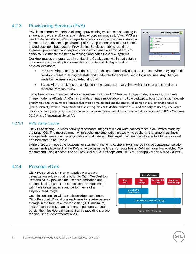
4.2.3 Provisioning Services (PVS) ............................................................................................................................. 47
4.2.4 Personal vDisk .................................................................................................................................................. 47
4.2.5 HDX 3D Pro ...................................................................................................................................................... 48
4.2.6 Citrix Profile Manager ....................................................................................................................................... 48
4.2.7 Citrix XenApp .................................................................................................................................................... 49
4.2.8 Local Host Cache ............................................................................................................................................. 51
4.2.9 Citrix NetScaler ................................................................................................................................................. 53
4.3 NVIDIA GRID vGPU ......................................................................................................................................... 54
4.3.1 vGPU Profiles ................................................................................................................................................... 55
5 Solution architecture for vSRN with XenDesktop ....................................................................................................... 62
5.1 Management server infrastructure .................................................................................................................... 62
5.1.1 SQL databases ................................................................................................................................................. 62
5.1.2 DNS .................................................................................................................................................................. 62
5.2 Storage architecture overview .......................................................................................................................... 63
5.2.1 vSAN local storage ........................................................................................................................................... 63
5.3 Virtual networking ............................................................................................................................................. 64
5.3.1 VSRN network configuration ............................................................................................................................ 64
5.3.2 VMware NSX .................................................................................................................................................... 67
5.4 Scaling Guidance.............................................................................................................................................. 69
5.5 Solution high availability ................................................................................................................................... 71
5.5.1 vSAN HA/ FTT configuration ............................................................................................................................ 71
5.5.2 vSphere HA ...................................................................................................................................................... 72
5 Dell VMware vSAN Ready Nodes for Citrix XenDesktop. | July 2017
5.5.3 SQL Server high availability ............................................................................................................................. 72
5.6 Citrix XenDesktop Communication Flow .......................................................................................................... 73
6 Solution performance and testing............................................................................................................................... 74
6.1 Test and Performance Analysis Methodology .................................................................................................. 74
6.1.1 Testing process ................................................................................................................................................ 74
6.1.2 Resource Monitoring ........................................................................................................................................ 77
6.1.3 Resource Utilization .......................................................................................................................................... 77
6.2 Test Configuration Details ................................................................................................................................ 78
6.2.1 Compute VM configurations ............................................................................................................................. 79
6.3 Test Results and Analysis ................................................................................................................................ 80
6.3.1 vSRN R730-C7 ................................................................................................................................................. 80
Acknowledgements ........................................................................................................................................................... 90
About the Authors ............................................................................................................................................................. 91
6 Dell VMware vSAN Ready Nodes for Citrix XenDesktop. | July 2017
1 Introduction
1.1 Purpose This document addresses the architecture design, configuration and implementation considerations for the
key components of the architecture required to deliver virtual desktops via Citrix XenDesktop on VMware
vSAN Ready Nodes (vSRN) with vSphere 6.0 Update 2 and VMware vSAN 6.2.
1.2 Scope Relative to delivering the virtual desktop environment, the objectives of this document are to:
Define the detailed technical design for the solution.
Define the hardware requirements to support the design.
Define the constraints, which are relevant to the design.
Define relevant risks, issues, assumptions and concessions – referencing existing ones where
possible.
Provide a breakdown of the design into key elements such that the reader receives an incremental or
modular explanation of the design.
Provide scaling component selection guidance.
1.3 What’s new Introduce vSAN Ready Nodes (vSRN)
Introduce Citrix XenDesktop on vSRN
7 Dell VMware vSAN Ready Nodes for Citrix XenDesktop. | July 2017
2 Solution architecture overview
2.1 Introduction Dell Wyse Datacenter solutions provide a number of deployment options to meet your desktop virtualization
requirements. Our solution is able to provide a compelling desktop experience to a range of employees within
your organization from task workers to knowledge workers to power users. The deployment options for Dell
Wyse Datacenter include:
Citrix Machine Creation Services(MCS)- Random/Non-Persistent
Citrix Machine Creation Services(MCS)- Static/ Persistent
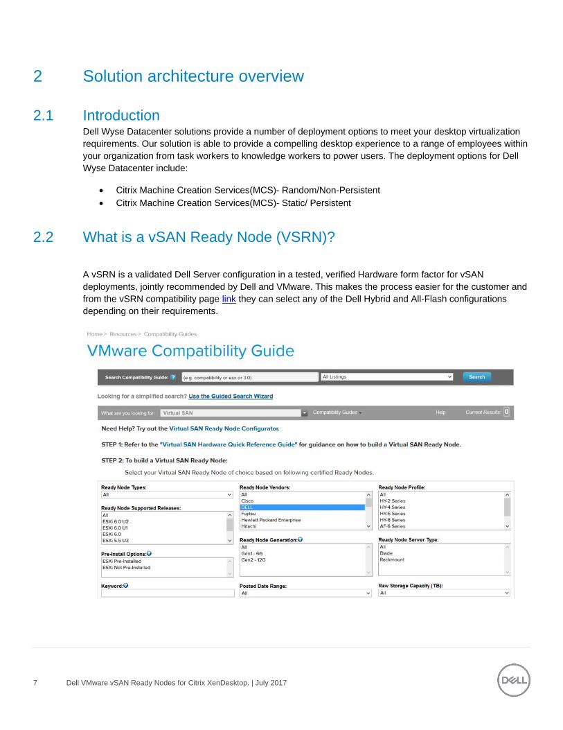
2.2 What is a vSAN Ready Node (VSRN)?
A vSRN is a validated Dell Server configuration in a tested, verified Hardware form factor for vSAN
deployments, jointly recommended by Dell and VMware. This makes the process easier for the customer and
from the vSRN compatibility page link they can select any of the Dell Hybrid and All-Flash configurations
depending on their requirements.

8 Dell VMware vSAN Ready Nodes for Citrix XenDesktop. | July 2017
2.3 Physical architecture overview The core vSRN architecture consists of a software-defined Shared Tier1 model. This consists of a Cache and
a Capacity Tier, the minimum requirements for which are 1 x SSD for the Cache Tier and 1 xHDD or SSD for
the Capacity Tier. The management and compute nodes are configured in the same vSRN Cluster and share
the vSAN datastore. The user data can be hosted via a file server residing within the vSAN file system.
2.4 Solution layers The vSRN Solution leverages a core set of hardware and software components consisting of five primary
layers:
Networking Layer
Compute Server Layer
Management Server Layer
Storage Layer (vSAN)
Thin Client Layer (please refer to section 3.4)
These components have been integrated and tested to provide the optimal balance of high performance and
lowest cost per user. The vSRN stack is designed to be cost effective allowing IT departments to implement
high-performance fully virtualized desktop environments.
Only a single high performance Dell Networking 10Gb 48-port switch is required to get started in the network
layer. This switch hosts all solution traffic consisting of 10Gb LAN sources for smaller stacks. The
management and vSAN traffic are separated out via VLAN across 2 x 10Gb NICs. When deploying larger
cluster configurations it may be optimal to split out the management and vSAN traffic. The Server
configurations are equipped with 4 x 10GB connections to facilitate this. When there is a requirement for 1Gb

9 Dell VMware vSAN Ready Nodes for Citrix XenDesktop. | July 2017
connectivity for DRAC/remote management so we can use an existing 1Gb ToR or add a Dell Networking
1Gb 48-port switch for this function.
The compute, management and storage layers are converged into a single server VSRN Series appliance
cluster, based on VMware vSphere. The recommended boundaries of an individual cluster are based on
number of the nodes supported for vSphere 6 which is currently 64.
Dell recommends that the VDI management infrastructure nodes be physically separated from the compute
resources. In this configuration both management and compute exist in the same vSAN Cluster but the
management node is reserved for management server VMs only and this will be expanded as needed
depending on the size of the cluster.
10 Dell VMware vSAN Ready Nodes for Citrix XenDesktop. | July 2017
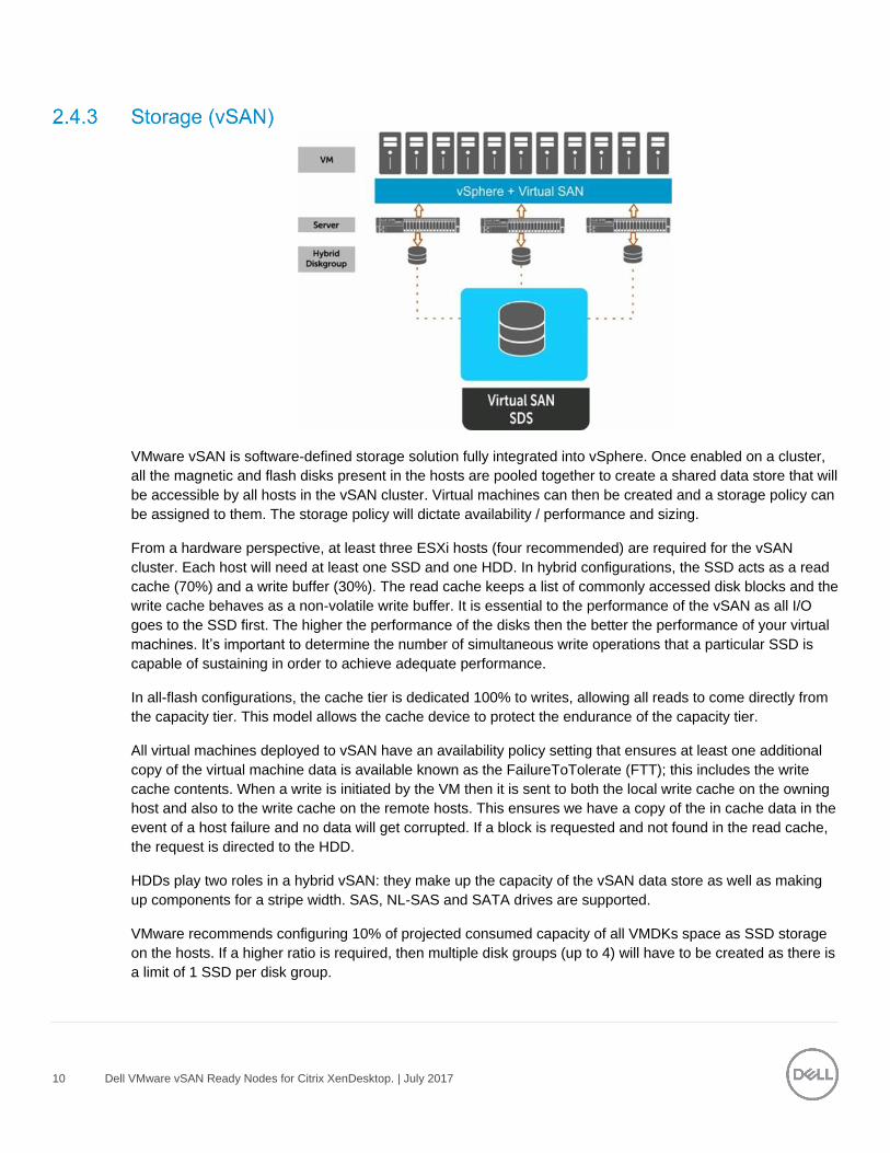
VMware vSAN is software-defined storage solution fully integrated into vSphere. Once enabled on a cluster,
all the magnetic and flash disks present in the hosts are pooled together to create a shared data store that will
be accessible by all hosts in the vSAN cluster. Virtual machines can then be created and a storage policy can
be assigned to them. The storage policy will dictate availability / performance and sizing.
From a hardware perspective, at least three ESXi hosts (four recommended) are required for the vSAN
cluster. Each host will need at least one SSD and one HDD. In hybrid configurations, the SSD acts as a read
cache (70%) and a write buffer (30%). The read cache keeps a list of commonly accessed disk blocks and the
write cache behaves as a non-volatile write buffer. It is essential to the performance of the vSAN as all I/O
goes to the SSD first. The higher the performance of the disks then the better the performance of your virtual
machines. It’s important to determine the number of simultaneous write operations that a particular SSD is
capable of sustaining in order to achieve adequate performance.
In all-flash configurations, the cache tier is dedicated 100% to writes, allowing all reads to come directly from
the capacity tier. This model allows the cache device to protect the endurance of the capacity tier.
All virtual machines deployed to vSAN have an availability policy setting that ensures at least one additional
copy of the virtual machine data is available known as the FailureToTolerate (FTT); this includes the write
cache contents. When a write is initiated by the VM then it is sent to both the local write cache on the owning
host and also to the write cache on the remote hosts. This ensures we have a copy of the in cache data in the
event of a host failure and no data will get corrupted. If a block is requested and not found in the read cache,
the request is directed to the HDD.
HDDs play two roles in a hybrid vSAN: they make up the capacity of the vSAN data store as well as making
up components for a stripe width. SAS, NL-SAS and SATA drives are supported.
VMware recommends configuring 10% of projected consumed capacity of all VMDKs space as SSD storage
on the hosts. If a higher ratio is required, then multiple disk groups (up to 4) will have to be created as there is
a limit of 1 SSD per disk group.
11 Dell VMware vSAN Ready Nodes for Citrix XenDesktop. | July 2017
vSAN implements a distributed RAID concept across all hosts in the cluster, so if a host or a component
within a host (e.g. an HDD or SSD) fails then virtual machines still have a full complement of data objects
available and can continue to run. This availability is defined on a per-VM basis through the use of VM
storage policies.
vSAN 6.2 provides two different configuration options, a hybrid configuration that leverages flash-based
devices for the cache tier and magnetic disks for the capacity tier, and an all-flash configuration. This delivers
enterprise performance and a resilient storage platform. The all-flash configuration uses flash for both the
cache tier and capacity tier.
There are two ways to build a vSAN cluster, build your custom configuration using the HCL link or choose the
Dell VMware Certified Ready Nodes link.
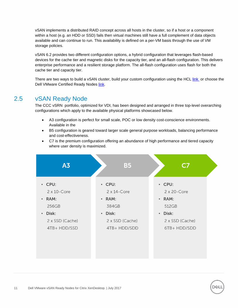
2.5 vSAN Ready Node The CCC vSRN portfolio, optimized for VDI, has been designed and arranged in three top-level overarching
configurations which apply to the available physical platforms showcased below.
A3 configuration is perfect for small scale, POC or low density cost-conscience environments.
Available in the
B5 configuration is geared toward larger scale general purpose workloads, balancing performance
and cost-effectiveness.
C7 is the premium configuration offering an abundance of high performance and tiered capacity
where user density is maximized.

12 Dell VMware vSAN Ready Nodes for Citrix XenDesktop. | July 2017
The Shared Tier 1 vSRN Hybrid configuration model provides a scalable rack-based configuration that hosts
user VDI sessions on local SSD (cache) and spinning disk (capacity) in the compute layer. The All-Flash
configuration uses SSDs for the capacity layer.
The A3 configuration below consists of two disk group, each diskgroup consists of 1 x SSD for cache & 1 x
HDD/SSD for capacity.
The B5 configuration below consists of two disk group And each diskgroup consists of 1 x SSD for cache & 2
x HDD/SSD for capacity.
The C7 configuration below consists of two disk group And each diskgroup consists of 1 x SSD for cache & 3
x HDD/SSD for capacity.
13 Dell VMware vSAN Ready Nodes for Citrix XenDesktop. | July 2017
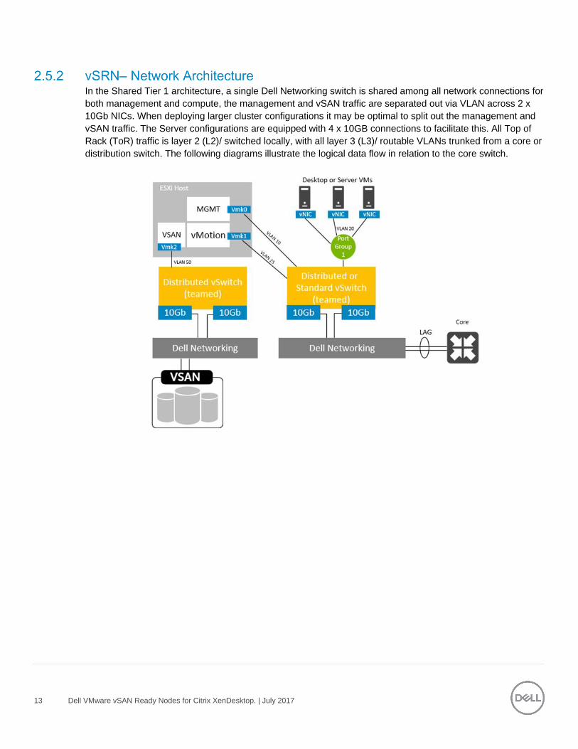
In the Shared Tier 1 architecture, a single Dell Networking switch is shared among all network connections for
both management and compute, the management and vSAN traffic are separated out via VLAN across 2 x
10Gb NICs. When deploying larger cluster configurations it may be optimal to split out the management and
vSAN traffic. The Server configurations are equipped with 4 x 10GB connections to facilitate this. All Top of
Rack (ToR) traffic is layer 2 (L2)/ switched locally, with all layer 3 (L3)/ routable VLANs trunked from a core or
distribution switch. The following diagrams illustrate the logical data flow in relation to the core switch.
14 Dell VMware vSAN Ready Nodes for Citrix XenDesktop. | July 2017
3 Hardware components
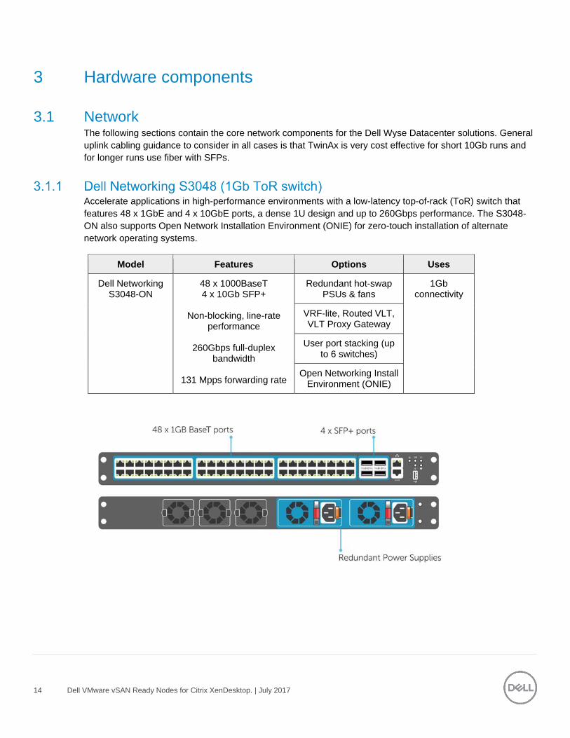
3.1 Network The following sections contain the core network components for the Dell Wyse Datacenter solutions. General
uplink cabling guidance to consider in all cases is that TwinAx is very cost effective for short 10Gb runs and
for longer runs use fiber with SFPs.
Accelerate applications in high-performance environments with a low-latency top-of-rack (ToR) switch that
features 48 x 1GbE and 4 x 10GbE ports, a dense 1U design and up to 260Gbps performance. The S3048-
ON also supports Open Network Installation Environment (ONIE) for zero-touch installation of alternate
network operating systems.
Model Features Options Uses
Dell Networking S3048-ON
48 x 1000BaseT 4 x 10Gb SFP+
Non-blocking, line-rate
performance
260Gbps full-duplex bandwidth
131 Mpps forwarding rate
Redundant hot-swap PSUs & fans
1Gb connectivity
VRF-lite, Routed VLT, VLT Proxy Gateway
User port stacking (up to 6 switches)
Open Networking Install Environment (ONIE)
15 Dell VMware vSAN Ready Nodes for Citrix XenDesktop. | July 2017
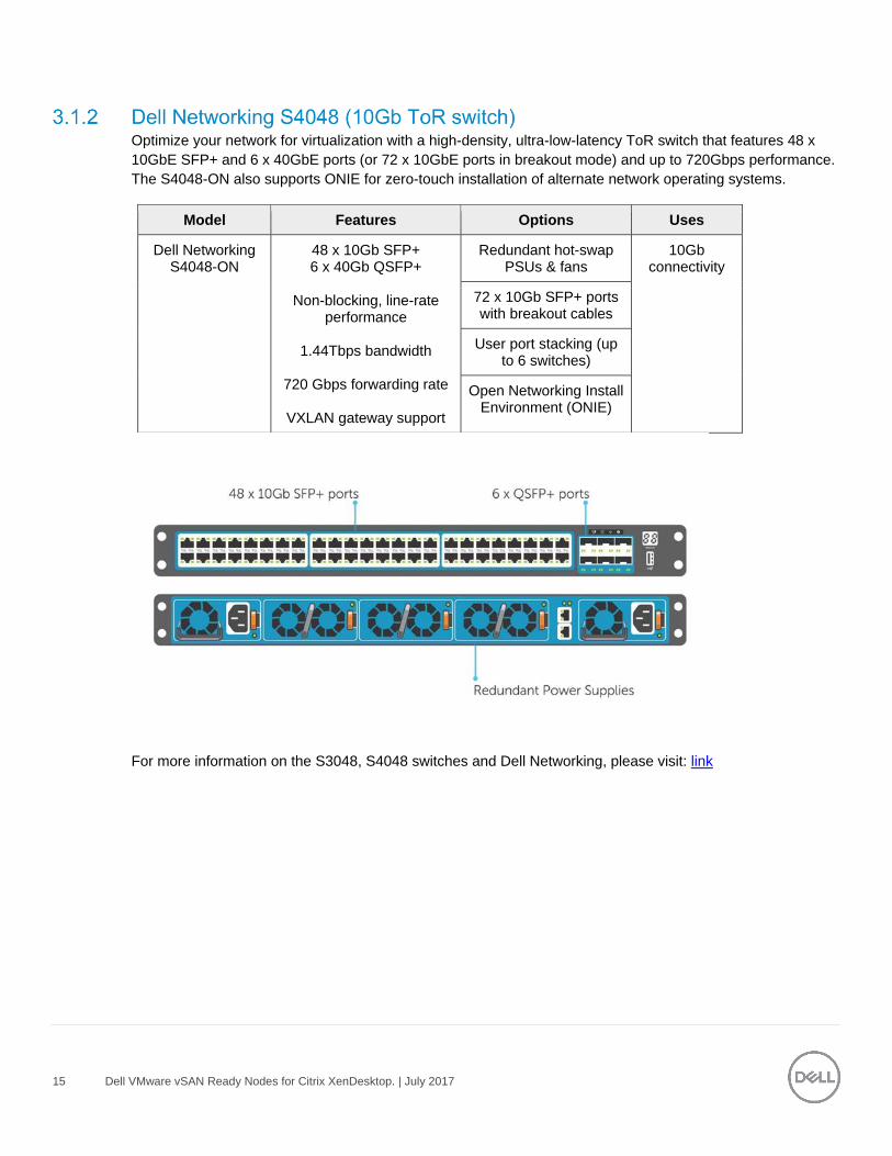
Optimize your network for virtualization with a high-density, ultra-low-latency ToR switch that features 48 x
10GbE SFP+ and 6 x 40GbE ports (or 72 x 10GbE ports in breakout mode) and up to 720Gbps performance.
The S4048-ON also supports ONIE for zero-touch installation of alternate network operating systems.
Model Features Options Uses
Dell Networking S4048-ON
48 x 10Gb SFP+ 6 x 40Gb QSFP+
Non-blocking, line-rate
performance
1.44Tbps bandwidth
720 Gbps forwarding rate
VXLAN gateway support
Redundant hot-swap PSUs & fans
10Gb connectivity
72 x 10Gb SFP+ ports with breakout cables
User port stacking (up to 6 switches)
Open Networking Install Environment (ONIE)
For more information on the S3048, S4048 switches and Dell Networking, please visit: link
16 Dell VMware vSAN Ready Nodes for Citrix XenDesktop. | July 2017
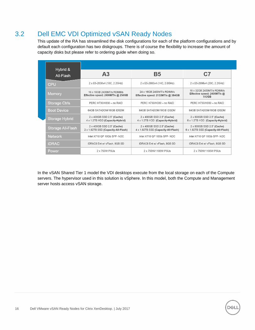
3.2 Dell EMC VDI Optimized vSAN Ready Nodes This update of the RA has streamlined the disk configurations for each of the platform configurations and by
default each configuration has two diskgroups. There is of course the flexibility to increase the amount of
capacity disks but please refer to ordering guide when doing so.
In the vSAN Shared Tier 1 model the VDI desktops execute from the local storage on each of the Compute
servers. The hypervisor used in this solution is vSphere. In this model, both the Compute and Management
server hosts access vSAN storage.
17 Dell VMware vSAN Ready Nodes for Citrix XenDesktop. | July 2017
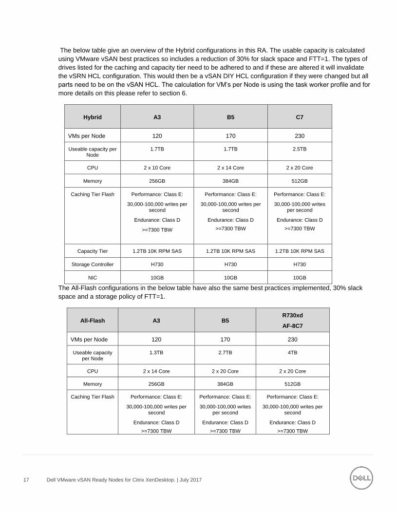
The below table give an overview of the Hybrid configurations in this RA. The usable capacity is calculated
using VMware vSAN best practices so includes a reduction of 30% for slack space and FTT=1. The types of
drives listed for the caching and capacity tier need to be adhered to and if these are altered it will invalidate
the vSRN HCL configuration. This would then be a vSAN DIY HCL configuration if they were changed but all
parts need to be on the vSAN HCL. The calculation for VM’s per Node is using the task worker profile and for
more details on this please refer to section 6.
Hybrid A3 B5 C7
VMs per Node 120 170 230
Useable capacity per Node
1.7TB 1.7TB 2.5TB
CPU 2 x 10 Core 2 x 14 Core 2 x 20 Core
Memory 256GB 384GB 512GB
Caching Tier Flash Performance: Class E:
30,000-100,000 writes per second
Endurance: Class D
>=7300 TBW
Performance: Class E:
30,000-100,000 writes per second
Endurance: Class D
>=7300 TBW
Performance: Class E:
30,000-100,000 writes per second
Endurance: Class D
>=7300 TBW
Capacity Tier 1.2TB 10K RPM SAS 1.2TB 10K RPM SAS 1.2TB 10K RPM SAS
Storage Controller H730 H730 H730
NIC 10GB 10GB 10GB
The All-Flash configurations in the below table have also the same best practices implemented, 30% slack
space and a storage policy of FTT=1.
All-Flash A3 B5 R730xd
AF-8C7
VMs per Node 120 170 230
Useable capacity per Node
1.3TB 2.7TB 4TB
CPU 2 x 14 Core 2 x 20 Core 2 x 20 Core
Memory 256GB 384GB 512GB
Caching Tier Flash Performance: Class E:
30,000-100,000 writes per second
Endurance: Class D
>=7300 TBW
Performance: Class E:
30,000-100,000 writes per second
Endurance: Class D
>=7300 TBW
Performance: Class E:
30,000-100,000 writes per second
Endurance: Class D
>=7300 TBW

18 Dell VMware vSAN Ready Nodes for Citrix XenDesktop. | July 2017
Capacity Tier Performance: Class D:
20,000-30,000 writes per second
Endurance: Class D
>=7300 TBW
Performance: Class E:
30,000-100,000 writes per second
Endurance: Class D
>=7300 TBW
Performance: Class D
20,000-30,000 writes per second
Endurance: Class B
>=1825 TBW
Storage Controller HBA330 HBA330 HBA330
NIC 10GB 10GB 10GB
19 Dell VMware vSAN Ready Nodes for Citrix XenDesktop. | July 2017
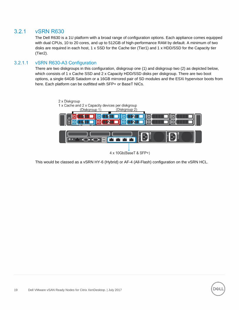
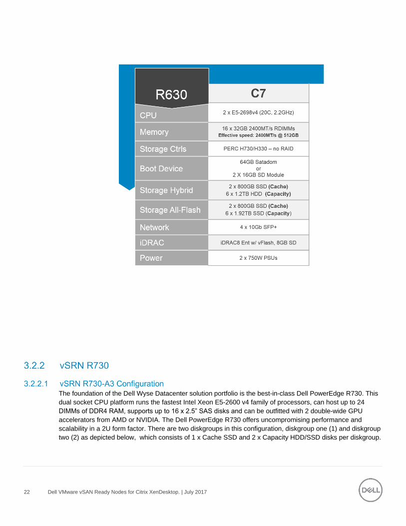
The Dell R630 is a 1U platform with a broad range of configuration options. Each appliance comes equipped
with dual CPUs, 10 to 20 cores, and up to 512GB of high-performance RAM by default. A minimum of two
disks are required in each host, 1 x SSD for the Cache tier (Tier1) and 1 x HDD/SSD for the Capacity tier
(Tier2).
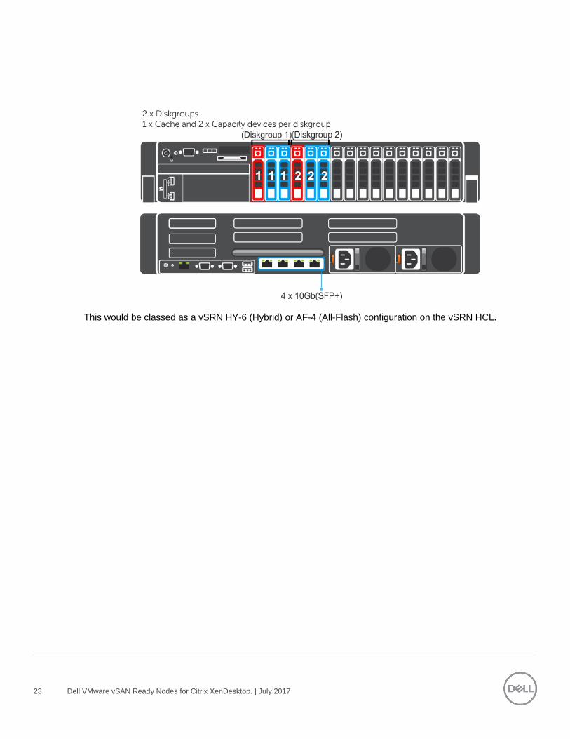
There are two diskgroups in this configuration, diskgroup one (1) and diskgroup two (2) as depicted below,
which consists of 1 x Cache SSD and 2 x Capacity HDD/SSD disks per diskgroup. There are two boot
options, a single 64GB Satadom or a 16GB mirrored pair of SD modules and the ESXi hypervisor boots from
here. Each platform can be outfitted with SFP+ or BaseT NICs.
This would be classed as a vSRN HY-6 (Hybrid) or AF-4 (All-Flash) configuration on the vSRN HCL.
20 Dell VMware vSAN Ready Nodes for Citrix XenDesktop. | July 2017
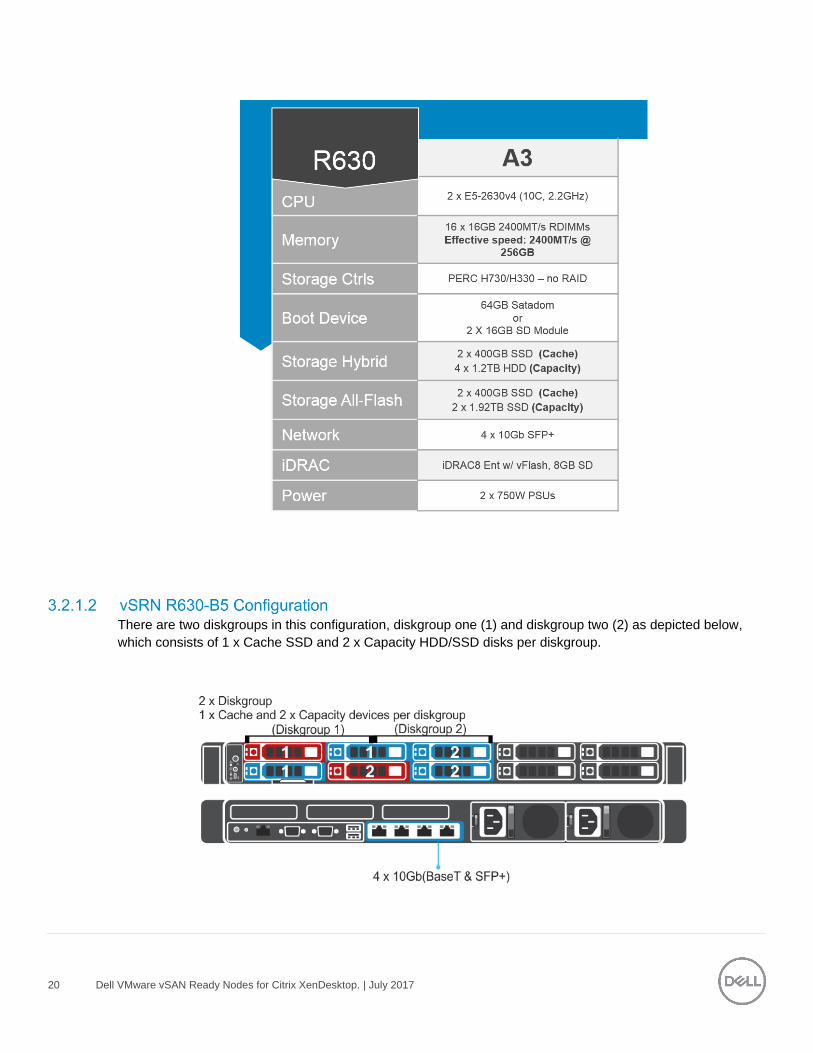
There are two diskgroups in this configuration, diskgroup one (1) and diskgroup two (2) as depicted below,
which consists of 1 x Cache SSD and 2 x Capacity HDD/SSD disks per diskgroup.
21 Dell VMware vSAN Ready Nodes for Citrix XenDesktop. | July 2017
This would be classed as a vSRN HY-6 (Hybrid) or AF-4 (All-Flash) configuration on the vSRN HCL.
There are two diskgroups in this configuration, diskgroup one (1) and diskgroup two (2) as depicted below,
which consists of 1 x Cache SSD and 2 x Capacity HDD/SSD disks per diskgroup.
This would be classed as a vSRN HY-8 (Hybrid) or AF-8 (All-Flash) configuration on the vSRN HCL.
22 Dell VMware vSAN Ready Nodes for Citrix XenDesktop. | July 2017
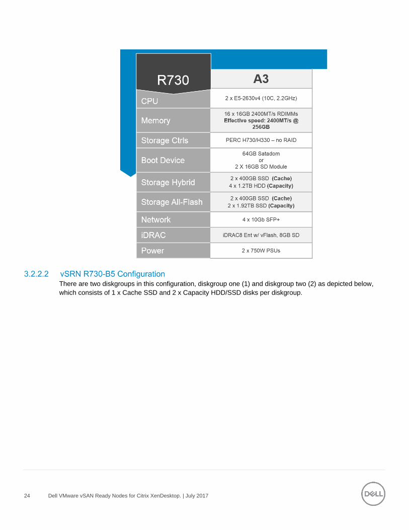
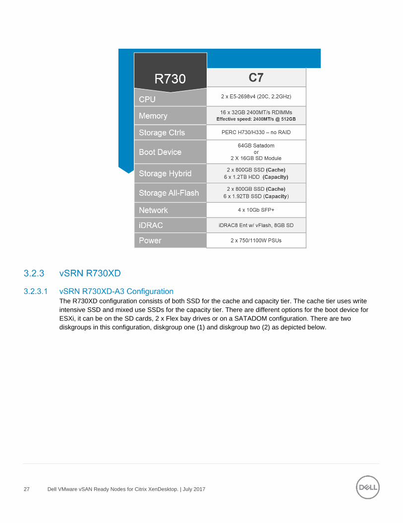
The foundation of the Dell Wyse Datacenter solution portfolio is the best-in-class Dell PowerEdge R730. This
dual socket CPU platform runs the fastest Intel Xeon E5-2600 v4 family of processors, can host up to 24
DIMMs of DDR4 RAM, supports up to 16 x 2.5” SAS disks and can be outfitted with 2 double-wide GPU
accelerators from AMD or NVIDIA. The Dell PowerEdge R730 offers uncompromising performance and
scalability in a 2U form factor. There are two diskgroups in this configuration, diskgroup one (1) and diskgroup
two (2) as depicted below, which consists of 1 x Cache SSD and 2 x Capacity HDD/SSD disks per diskgroup.
23 Dell VMware vSAN Ready Nodes for Citrix XenDesktop. | July 2017
This would be classed as a vSRN HY-6 (Hybrid) or AF-4 (All-Flash) configuration on the vSRN HCL.
24 Dell VMware vSAN Ready Nodes for Citrix XenDesktop. | July 2017
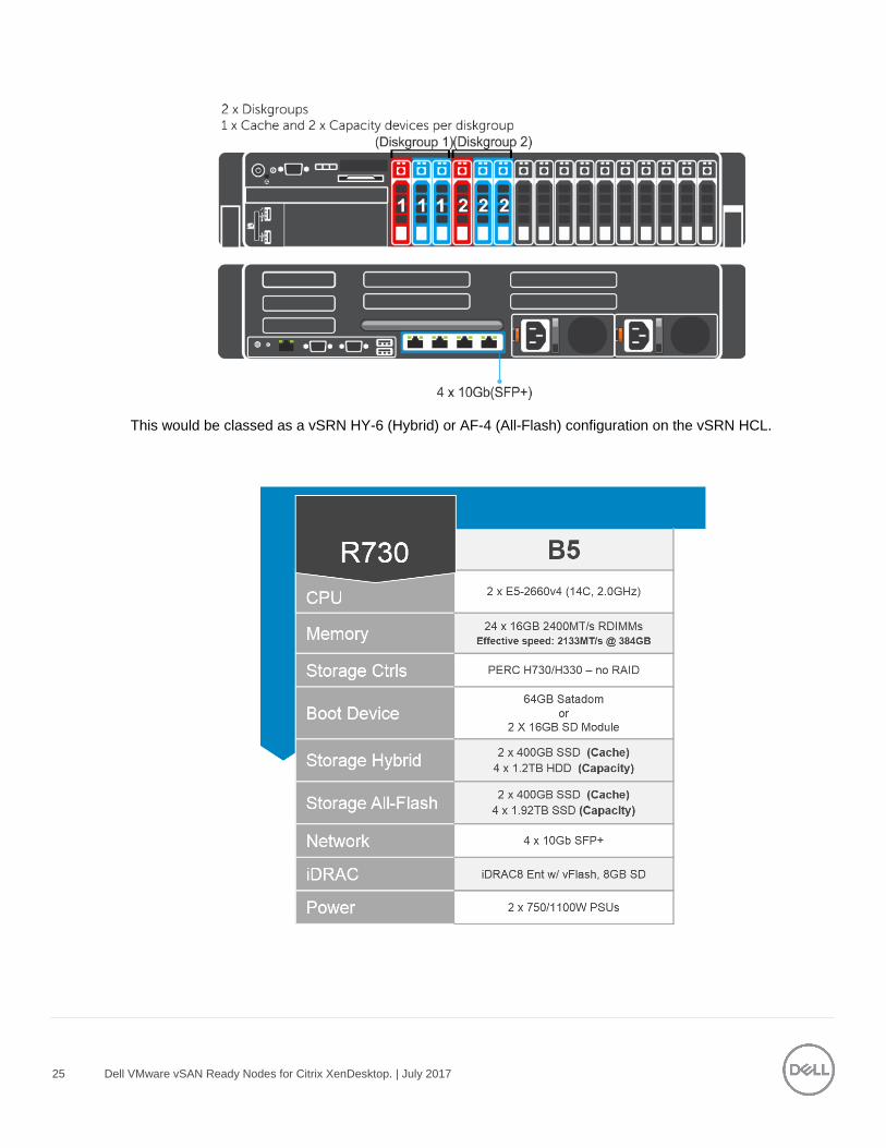
There are two diskgroups in this configuration, diskgroup one (1) and diskgroup two (2) as depicted below,
which consists of 1 x Cache SSD and 2 x Capacity HDD/SSD disks per diskgroup.
25 Dell VMware vSAN Ready Nodes for Citrix XenDesktop. | July 2017
This would be classed as a vSRN HY-6 (Hybrid) or AF-4 (All-Flash) configuration on the vSRN HCL.
26 Dell VMware vSAN Ready Nodes for Citrix XenDesktop. | July 2017
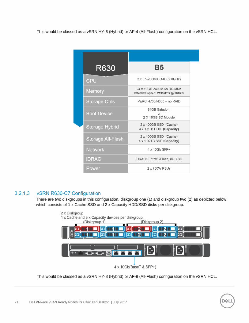
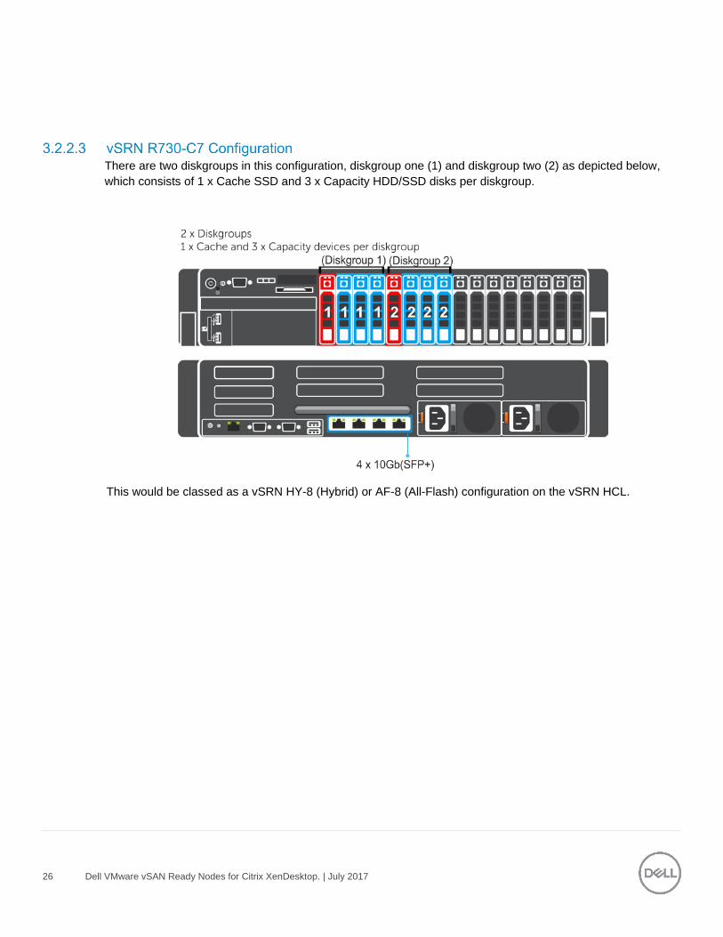
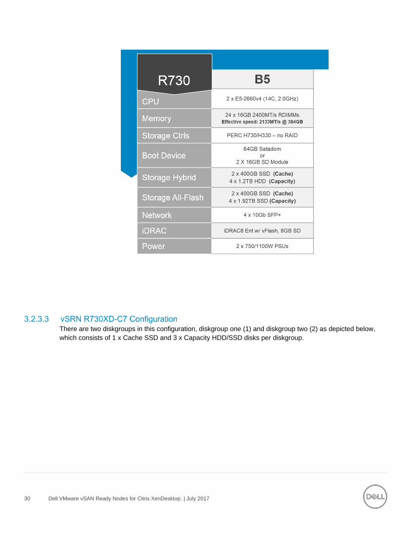
There are two diskgroups in this configuration, diskgroup one (1) and diskgroup two (2) as depicted below,
which consists of 1 x Cache SSD and 3 x Capacity HDD/SSD disks per diskgroup.
This would be classed as a vSRN HY-8 (Hybrid) or AF-8 (All-Flash) configuration on the vSRN HCL.
27 Dell VMware vSAN Ready Nodes for Citrix XenDesktop. | July 2017
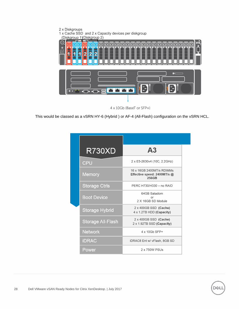
The R730XD configuration consists of both SSD for the cache and capacity tier. The cache tier uses write
intensive SSD and mixed use SSDs for the capacity tier. There are different options for the boot device for
ESXi, it can be on the SD cards, 2 x Flex bay drives or on a SATADOM configuration. There are two
diskgroups in this configuration, diskgroup one (1) and diskgroup two (2) as depicted below.
28 Dell VMware vSAN Ready Nodes for Citrix XenDesktop. | July 2017
This would be classed as a vSRN HY-6 (Hybrid ) or AF-4 (All-Flash) configuration on the vSRN HCL.
29 Dell VMware vSAN Ready Nodes for Citrix XenDesktop. | July 2017
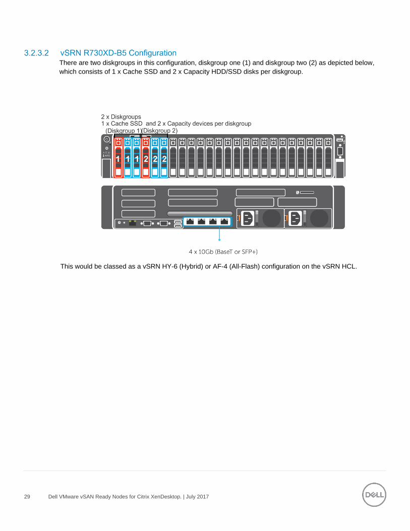
There are two diskgroups in this configuration, diskgroup one (1) and diskgroup two (2) as depicted below,
which consists of 1 x Cache SSD and 2 x Capacity HDD/SSD disks per diskgroup.
This would be classed as a vSRN HY-6 (Hybrid) or AF-4 (All-Flash) configuration on the vSRN HCL.
30 Dell VMware vSAN Ready Nodes for Citrix XenDesktop. | July 2017
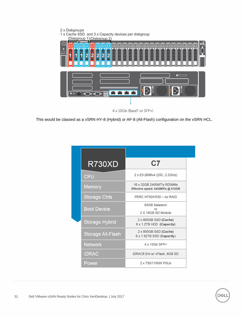
There are two diskgroups in this configuration, diskgroup one (1) and diskgroup two (2) as depicted below,
which consists of 1 x Cache SSD and 3 x Capacity HDD/SSD disks per diskgroup.
31 Dell VMware vSAN Ready Nodes for Citrix XenDesktop. | July 2017
This would be classed as a vSRN HY-8 (Hybrid) or AF-8 (All-Flash) configuration on the vSRN HCL.
32 Dell VMware vSAN Ready Nodes for Citrix XenDesktop. | July 2017
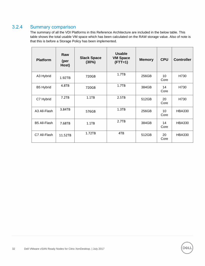
The summary of all the VDI Platforms in this Reference Architecture are included in the below table. This
table shows the total usable VM space which has been calculated on the RAW storage value. Also of note is
that this is before a Storage Policy has been implemented.
Platform
Raw
(per Host)
Slack Space (30%)
Usable
VM Space (FTT=1)
Memory CPU Controller
A3 Hybrid
1.92TB 720GB 1.7TB
256GB 10 Core
H730
B5 Hybrid 4.8TB
720GB 1.7TB
384GB 14 Core
H730
C7 Hybrid 7.2TB
1.1TB
2.5TB
512GB 20 Core
H730
A3 All-Flash 3.84TB
576GB 1.3TB
256GB 10 Core
HBA330
B5 All-Flash 7.68TB 1.1TB 2.7TB
384GB 14 Core
HBA330
C7 All-Flash 11.52TB 1.72TB
4TB
512GB 20 Core
HBA330
33 Dell VMware vSAN Ready Nodes for Citrix XenDesktop. | July 2017
3.3 GPUs
Accelerate your most demanding enterprise data center workloads with NVIDIA® Tesla® GPU accelerators.
Scientists can now crunch through petabytes of data up to 10x faster than with CPUs in applications ranging
from energy exploration to deep learning. In addition, Tesla accelerators deliver the horsepower needed to
run bigger simulations faster than ever before. For enterprises deploying VDI, Tesla accelerators are perfect
for accelerating virtual desktops.
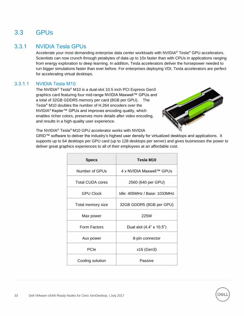
The NVIDIA® Tesla® M10 is a dual-slot 10.5 inch PCI Express Gen3
graphics card featuring four mid-range NVIDIA Maxwell™ GPUs and
a total of 32GB GDDR5 memory per card (8GB per GPU). The
Tesla® M10 doubles the number of H.264 encoders over the
NVIDIA® Kepler™ GPUs and improves encoding quality, which
enables richer colors, preserves more details after video encoding,
and results in a high-quality user experience.
The NVIDIA® Tesla® M10 GPU accelerator works with NVIDIA
GRID™ software to deliver the industry’s highest user density for virtualized desktops and applications. It
supports up to 64 desktops per GPU card (up to 128 desktops per server) and gives businesses the power to
deliver great graphics experiences to all of their employees at an affordable cost.
Specs Tesla M10
Number of GPUs 4 x NVIDIA Maxwell™ GPUs
Total CUDA cores 2560 (640 per GPU)
GPU Clock Idle: 405MHz / Base: 1033MHz
Total memory size 32GB GDDR5 (8GB per GPU)
Max power 225W
Form Factors Dual slot (4.4” x 10.5”)
Aux power 8-pin connector
PCIe x16 (Gen3)
Cooling solution Passive
34 Dell VMware vSAN Ready Nodes for Citrix XenDesktop. | July 2017
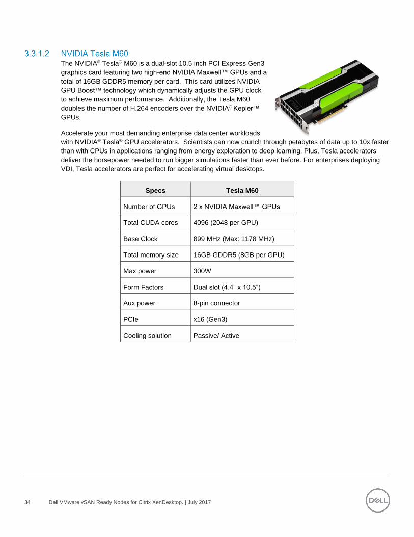
The NVIDIA® Tesla® M60 is a dual-slot 10.5 inch PCI Express Gen3
graphics card featuring two high-end NVIDIA Maxwell™ GPUs and a
total of 16GB GDDR5 memory per card. This card utilizes NVIDIA
GPU Boost™ technology which dynamically adjusts the GPU clock
to achieve maximum performance. Additionally, the Tesla M60
doubles the number of H.264 encoders over the NVIDIA® Kepler™
GPUs.
Accelerate your most demanding enterprise data center workloads
with NVIDIA® Tesla® GPU accelerators. Scientists can now crunch through petabytes of data up to 10x faster
than with CPUs in applications ranging from energy exploration to deep learning. Plus, Tesla accelerators
deliver the horsepower needed to run bigger simulations faster than ever before. For enterprises deploying
VDI, Tesla accelerators are perfect for accelerating virtual desktops.
Specs Tesla M60
Number of GPUs 2 x NVIDIA Maxwell™ GPUs Total CUDA cores 4096 (2048 per GPU)
Base Clock 899 MHz (Max: 1178 MHz)
Total memory size 16GB GDDR5 (8GB per GPU)
Max power 300W
Form Factors Dual slot (4.4” x 10.5”)
Aux power 8-pin connector
PCIe x16 (Gen3)
Cooling solution Passive/ Active
35 Dell VMware vSAN Ready Nodes for Citrix XenDesktop. | July 2017
3.4 Dell Wyse Thin Clients The following Dell Wyse clients will deliver a superior Citrix user experience and are the recommended
choices for this solution.
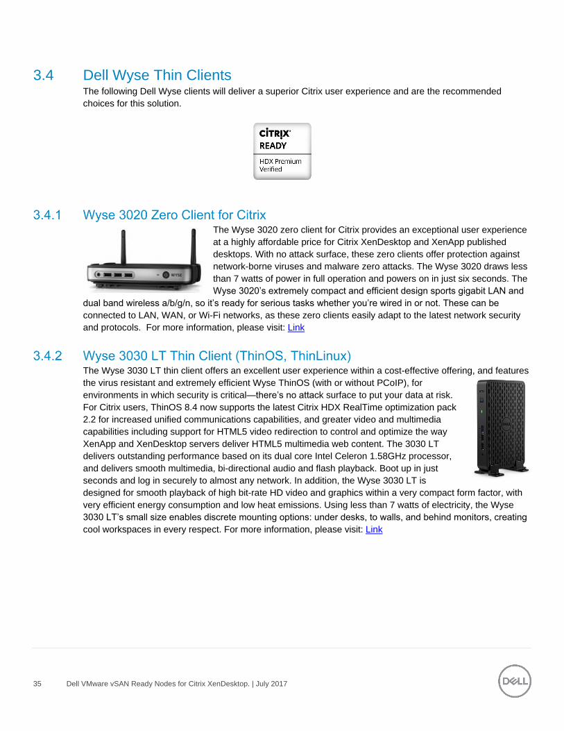
The Wyse 3020 zero client for Citrix provides an exceptional user experience
at a highly affordable price for Citrix XenDesktop and XenApp published
desktops. With no attack surface, these zero clients offer protection against
network-borne viruses and malware zero attacks. The Wyse 3020 draws less
than 7 watts of power in full operation and powers on in just six seconds. The
Wyse 3020’s extremely compact and efficient design sports gigabit LAN and
dual band wireless a/b/g/n, so it’s ready for serious tasks whether you’re wired in or not. These can be
connected to LAN, WAN, or Wi-Fi networks, as these zero clients easily adapt to the latest network security
and protocols. For more information, please visit: Link
The Wyse 3030 LT thin client offers an excellent user experience within a cost-effective offering, and features
the virus resistant and extremely efficient Wyse ThinOS (with or without PCoIP), for
environments in which security is critical—there’s no attack surface to put your data at risk.
For Citrix users, ThinOS 8.4 now supports the latest Citrix HDX RealTime optimization pack
2.2 for increased unified communications capabilities, and greater video and multimedia
capabilities including support for HTML5 video redirection to control and optimize the way
XenApp and XenDesktop servers deliver HTML5 multimedia web content. The 3030 LT
delivers outstanding performance based on its dual core Intel Celeron 1.58GHz processor,
and delivers smooth multimedia, bi-directional audio and flash playback. Boot up in just
seconds and log in securely to almost any network. In addition, the Wyse 3030 LT is
designed for smooth playback of high bit-rate HD video and graphics within a very compact form factor, with
very efficient energy consumption and low heat emissions. Using less than 7 watts of electricity, the Wyse
3030 LT’s small size enables discrete mounting options: under desks, to walls, and behind monitors, creating
cool workspaces in every respect. For more information, please visit: Link
36 Dell VMware vSAN Ready Nodes for Citrix XenDesktop. | July 2017
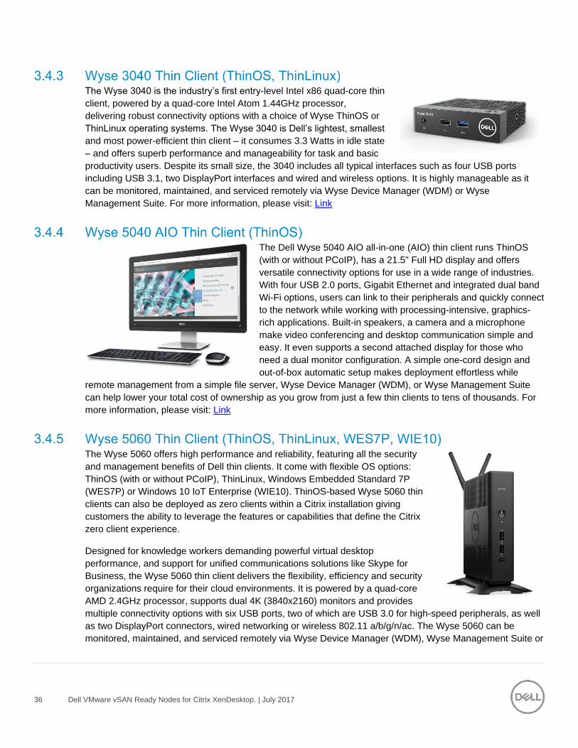
The Wyse 3040 is the industry’s first entry-level Intel x86 quad-core thin
client, powered by a quad-core Intel Atom 1.44GHz processor,
delivering robust connectivity options with a choice of Wyse ThinOS or
ThinLinux operating systems. The Wyse 3040 is Dell’s lightest, smallest
and most power-efficient thin client – it consumes 3.3 Watts in idle state
– and offers superb performance and manageability for task and basic
productivity users. Despite its small size, the 3040 includes all typical interfaces such as four USB ports
including USB 3.1, two DisplayPort interfaces and wired and wireless options. It is highly manageable as it
can be monitored, maintained, and serviced remotely via Wyse Device Manager (WDM) or Wyse
Management Suite. For more information, please visit: Link
The Dell Wyse 5040 AIO all-in-one (AIO) thin client runs ThinOS
(with or without PCoIP), has a 21.5" Full HD display and offers
versatile connectivity options for use in a wide range of industries.
With four USB 2.0 ports, Gigabit Ethernet and integrated dual band
Wi-Fi options, users can link to their peripherals and quickly connect
to the network while working with processing-intensive, graphics-
rich applications. Built-in speakers, a camera and a microphone
make video conferencing and desktop communication simple and
easy. It even supports a second attached display for those who
need a dual monitor configuration. A simple one-cord design and
out-of-box automatic setup makes deployment effortless while
remote management from a simple file server, Wyse Device Manager (WDM), or Wyse Management Suite
can help lower your total cost of ownership as you grow from just a few thin clients to tens of thousands. For
more information, please visit: Link
The Wyse 5060 offers high performance and reliability, featuring all the security
and management benefits of Dell thin clients. It come with flexible OS options:
ThinOS (with or without PCoIP), ThinLinux, Windows Embedded Standard 7P
(WES7P) or Windows 10 IoT Enterprise (WIE10). ThinOS-based Wyse 5060 thin
clients can also be deployed as zero clients within a Citrix installation giving
customers the ability to leverage the features or capabilities that define the Citrix
zero client experience.
Designed for knowledge workers demanding powerful virtual desktop
performance, and support for unified communications solutions like Skype for
Business, the Wyse 5060 thin client delivers the flexibility, efficiency and security
organizations require for their cloud environments. It is powered by a quad-core
AMD 2.4GHz processor, supports dual 4K (3840x2160) monitors and provides
multiple connectivity options with six USB ports, two of which are USB 3.0 for high-speed peripherals, as well
as two DisplayPort connectors, wired networking or wireless 802.11 a/b/g/n/ac. The Wyse 5060 can be
monitored, maintained, and serviced remotely via Wyse Device Manager (WDM), Wyse Management Suite or
37 Dell VMware vSAN Ready Nodes for Citrix XenDesktop. | July 2017
Microsoft SCCM (5060 with Windows versions). Customers choosing WIE10 licenses can save about
$50/device/year as WIE10 qualifies under Microsoft Software Insurance, without the need to have more
expensive VDA licenses to connect to a Windows virtual desktop. For more information, please visit: Link
The versatile Dell Wyse 7020 thin client is a powerful endpoint platform for virtual
desktop environments. It is available with Windows Embedded Standard 7/7P/8
(WES), Windows 10 IoT Enterprise (WIE10) and Wyse ThinLinux operating systems
and it supports a broad range of fast, flexible connectivity options so that users can
connect their favorite peripherals while working with processing-intensive, graphics-
rich applications. This 64-bit thin client delivers a great user experience and support
for local applications while ensuring security with features such as Trusted Platform
Module (TPM), BitLocker Drive Encryption, Secure Boot, and Windows Defender.
Designed to provide a superior user experience, Windows 10 IoT features broad
broker support including Citrix XenDesktop, Microsoft RDS and VMware Horizon, and support for unified
communication platforms including Skype for Business, Lync 2013 and Lync 2010. For additional security,
With a powerful quad core AMD G Series APU in a compact chassis with dual-HD monitor support, the Wyse
7020 thin client delivers stunning performance and display capabilities across 2D, 3D and HD video
applications. Its silent diskless and fan less design helps reduce power usage to just a fraction (it only
consumes about 15 watts) of that used in traditional desktops. Wyse Device Manager (WDM) helps lower the
total cost of ownership for large deployments and offers remote enterprise-wide management that scales from
just a few to tens of thousands of cloud clients. Customers choosing WIE10 licenses can save about
$50/device/year as WIE10 qualifies under Microsoft Software Insurance, without the need to have more
expensive VDA licenses to connect to a Windows virtual desktop. For more information, please visit Link
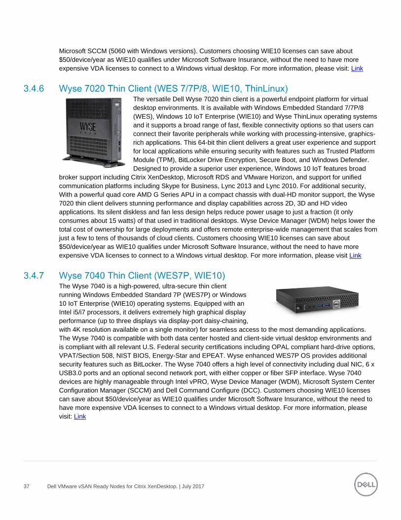
The Wyse 7040 is a high-powered, ultra-secure thin client
running Windows Embedded Standard 7P (WES7P) or Windows
10 IoT Enterprise (WIE10) operating systems. Equipped with an
Intel i5/i7 processors, it delivers extremely high graphical display
performance (up to three displays via display-port daisy-chaining,
with 4K resolution available on a single monitor) for seamless access to the most demanding applications.
The Wyse 7040 is compatible with both data center hosted and client-side virtual desktop environments and
is compliant with all relevant U.S. Federal security certifications including OPAL compliant hard-drive options,
VPAT/Section 508, NIST BIOS, Energy-Star and EPEAT. Wyse enhanced WES7P OS provides additional
security features such as BitLocker. The Wyse 7040 offers a high level of connectivity including dual NIC, 6 x
USB3.0 ports and an optional second network port, with either copper or fiber SFP interface. Wyse 7040
devices are highly manageable through Intel vPRO, Wyse Device Manager (WDM), Microsoft System Center
Configuration Manager (SCCM) and Dell Command Configure (DCC). Customers choosing WIE10 licenses
can save about $50/device/year as WIE10 qualifies under Microsoft Software Insurance, without the need to
have more expensive VDA licenses to connect to a Windows virtual desktop. For more information, please
visit: Link
38 Dell VMware vSAN Ready Nodes for Citrix XenDesktop. | July 2017
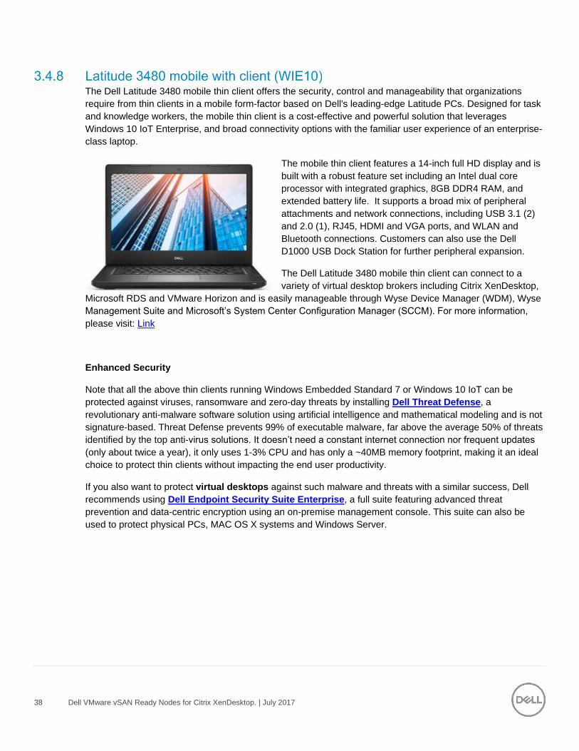
The Dell Latitude 3480 mobile thin client offers the security, control and manageability that organizations
require from thin clients in a mobile form-factor based on Dell's leading-edge Latitude PCs. Designed for task
and knowledge workers, the mobile thin client is a cost-effective and powerful solution that leverages
Windows 10 IoT Enterprise, and broad connectivity options with the familiar user experience of an enterprise-
class laptop.
The mobile thin client features a 14-inch full HD display and is
built with a robust feature set including an Intel dual core
processor with integrated graphics, 8GB DDR4 RAM, and
extended battery life. It supports a broad mix of peripheral
attachments and network connections, including USB 3.1 (2)
and 2.0 (1), RJ45, HDMI and VGA ports, and WLAN and
Bluetooth connections. Customers can also use the Dell
D1000 USB Dock Station for further peripheral expansion.
The Dell Latitude 3480 mobile thin client can connect to a
variety of virtual desktop brokers including Citrix XenDesktop,
Microsoft RDS and VMware Horizon and is easily manageable through Wyse Device Manager (WDM), Wyse
Management Suite and Microsoft’s System Center Configuration Manager (SCCM). For more information,
please visit: Link
Enhanced Security
Note that all the above thin clients running Windows Embedded Standard 7 or Windows 10 IoT can be
protected against viruses, ransomware and zero-day threats by installing Dell Threat Defense, a
revolutionary anti-malware software solution using artificial intelligence and mathematical modeling and is not
signature-based. Threat Defense prevents 99% of executable malware, far above the average 50% of threats
identified by the top anti-virus solutions. It doesn’t need a constant internet connection nor frequent updates
(only about twice a year), it only uses 1-3% CPU and has only a ~40MB memory footprint, making it an ideal
choice to protect thin clients without impacting the end user productivity.
If you also want to protect virtual desktops against such malware and threats with a similar success, Dell
recommends using Dell Endpoint Security Suite Enterprise, a full suite featuring advanced threat
prevention and data-centric encryption using an on-premise management console. This suite can also be
used to protect physical PCs, MAC OS X systems and Windows Server.
39 Dell VMware vSAN Ready Nodes for Citrix XenDesktop. | July 2017
4 Software Components
4.1 VMware The validation undertaken as part of this Reference Architecture was completed with vSphere 6.0 U2/vSAN
6.2 and Citrix XenDesktop 7.12. At the time of release of this document vSAN 6.5 with Citrix XenDekstop 7.12
are the latest supported releases but this document focuses on the validated configuration of vSAN 6.2 and
XD 7.12.
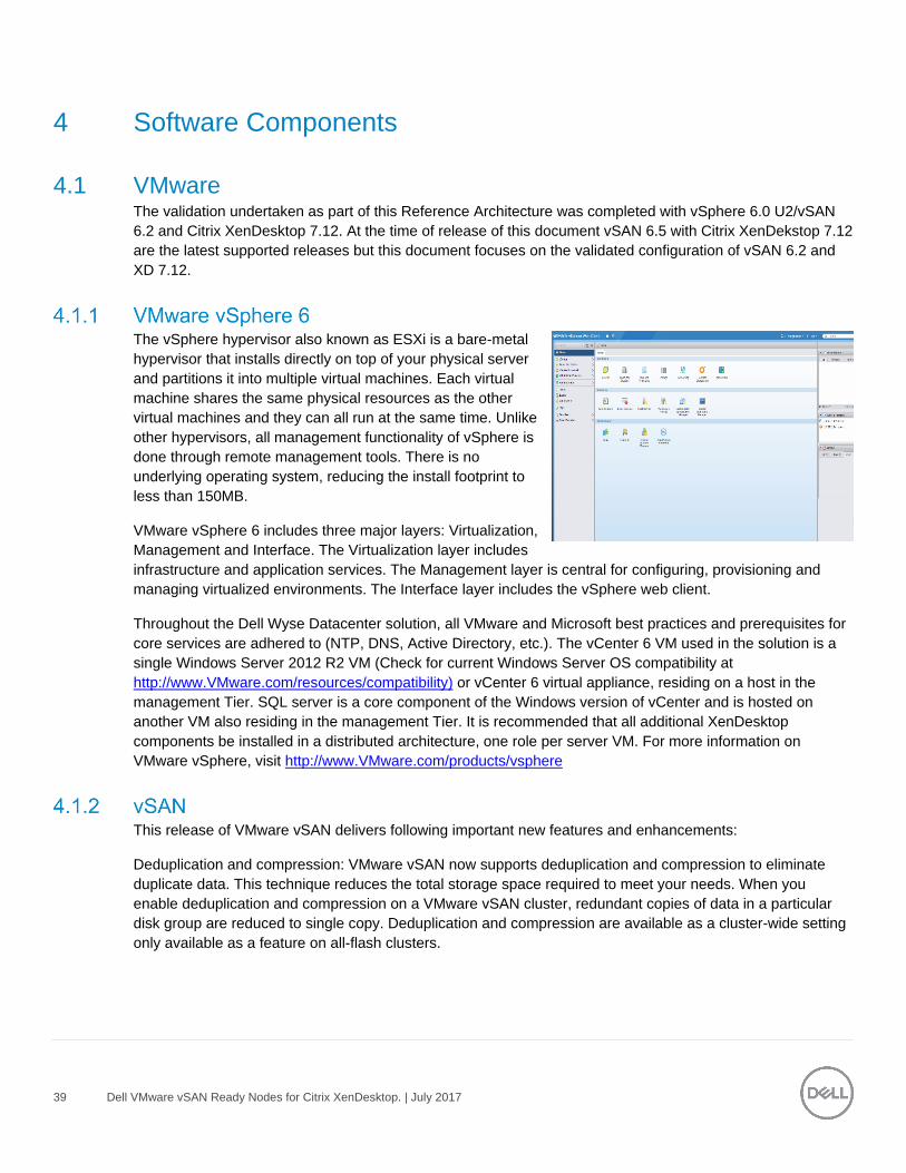
The vSphere hypervisor also known as ESXi is a bare-metal
hypervisor that installs directly on top of your physical server
and partitions it into multiple virtual machines. Each virtual
machine shares the same physical resources as the other
virtual machines and they can all run at the same time. Unlike
other hypervisors, all management functionality of vSphere is
done through remote management tools. There is no
underlying operating system, reducing the install footprint to
less than 150MB.
VMware vSphere 6 includes three major layers: Virtualization,
Management and Interface. The Virtualization layer includes
infrastructure and application services. The Management layer is central for configuring, provisioning and
managing virtualized environments. The Interface layer includes the vSphere web client.
Throughout the Dell Wyse Datacenter solution, all VMware and Microsoft best practices and prerequisites for
core services are adhered to (NTP, DNS, Active Directory, etc.). The vCenter 6 VM used in the solution is a
single Windows Server 2012 R2 VM (Check for current Windows Server OS compatibility at
http://www.VMware.com/resources/compatibility) or vCenter 6 virtual appliance, residing on a host in the
management Tier. SQL server is a core component of the Windows version of vCenter and is hosted on
another VM also residing in the management Tier. It is recommended that all additional XenDesktop
components be installed in a distributed architecture, one role per server VM. For more information on
VMware vSphere, visit http://www.VMware.com/products/vsphere
This release of VMware vSAN delivers following important new features and enhancements:
Deduplication and compression: VMware vSAN now supports deduplication and compression to eliminate
duplicate data. This technique reduces the total storage space required to meet your needs. When you
enable deduplication and compression on a VMware vSAN cluster, redundant copies of data in a particular
disk group are reduced to single copy. Deduplication and compression are available as a cluster-wide setting
only available as a feature on all-flash clusters.
40 Dell VMware vSAN Ready Nodes for Citrix XenDesktop. | July 2017
Enabling deduplication and compression can reduce the amount of storage consumed by as much as 7x.
Actual reduction numbers will vary as this depends primarily on the types of data present, number of duplicate
blocks, how much these data types can be compressed, and distribution of these unique blocks.
RAID 5 and RAID 6 erasure coding: VMware vSAN now supports both RAID 5 and RAID 6 erasure coding to
reduce the storage space required to protect your data. RAID 5 and RAID 6 are available as a policy attribute
for VMs in all-flash clusters.
Quality of Service: With the Quality of Service addition to VMware vSAN IOPS limits are now available.
Quality of service for VMware vSAN is a Storage Policy Based Management (SPBM) rule. Because quality of
service is applied to VMware vSAN objects through a Storage Policy, it can be applied to individual
components or the entire virtual machine without interrupting the operation of the virtual machine.
The term “noisy neighbor” is often used to describe when a workload monopolizes available I/O or other
resources, which negatively affect other workloads on the same platform.
For more information on what’s new in VMware vSAN Link
When determining the amount of capacity required for a VMware vSAN Design we need to pay close
attention to the NumberOfFailuresToTolerate(FTT) policy setting. The default storage policies that are
deployed have FTT=1 and that is the recommended default FTT policy setting. When we have FTT=1 set in
our policy it will mirror each VMDK in the virtual machine configuration, so if you have two VMDKs that are
40Gb & 20Gb respectively the amount of virtual machine space needed for that virtual machine is 120Gb
(40GB x 2 + 20GB x 2).
RAID-5 uses x1.33 the capacity with FTT=1 and requires a minimum of four hosts in the vSAN Cluster. RAID-
6 with FTT=2 uses x1.5 the capacity and requires a minimum of six hosts in the VMware vSAN Cluster.
The general recommendation for sizing flash capacity for VMware vSAN is to use 10% of the anticipated
storage capacity before the number for FTT is considered.
We also need to factor in how much free capacity or “Slack Space” needs to be preserved when designing
the capacity requirement for the VMware vSAN Cluster. The recommendation by VMware is that this should
be 30%. The reasoning for this slack space size that the VMware vSAN will begin automatically rebalancing
when a disk reaches the 80% full threshold and the additional 10% has been added as a buffer. This is not a
hard limit or set via a security policy so the customer can actually use this space but should be made aware of
the performance implications of going over the 80% full threshold. More information can be found on the
design and sizing of VMware vSAN6.2 Cluster here
The most signification new features in this latest version of VMware vSAN are Deduplication & Compression
and erasure coding. These features are only supported in an All-Flash VMware vSAN configuration. The
hesitance of a customer going the all flash route is cost but if you factor in the capacity savings achieved by
these new features is bridges the gap between the Hybrid & All Flash configurations.
The scenario below is using a VM which consumes 50 GB of space. The hybrid configuration has a default
FTT value of 1 and Failure Tolerance Method (FTM) of RAID-1 which has 2x overhead and with FTT=2 that
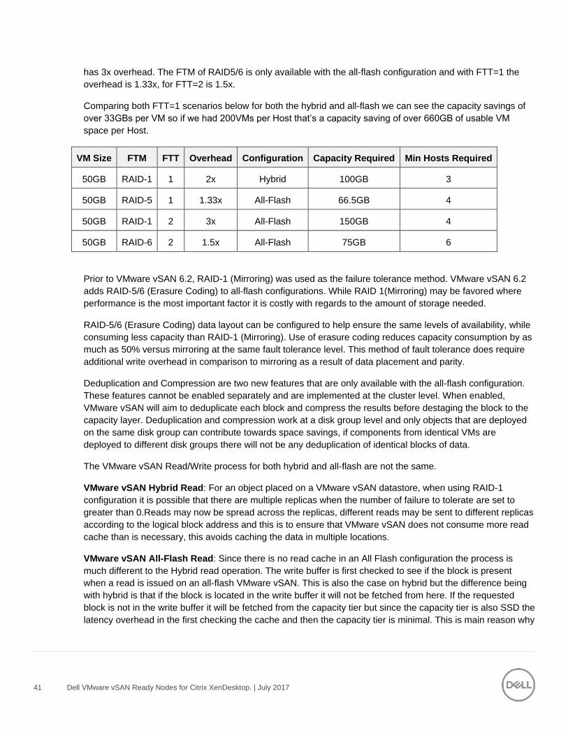
41 Dell VMware vSAN Ready Nodes for Citrix XenDesktop. | July 2017
has 3x overhead. The FTM of RAID5/6 is only available with the all-flash configuration and with FTT=1 the
overhead is 1.33x, for FTT=2 is 1.5x.
Comparing both FTT=1 scenarios below for both the hybrid and all-flash we can see the capacity savings of
over 33GBs per VM so if we had 200VMs per Host that’s a capacity saving of over 660GB of usable VM
space per Host.
VM Size FTM FTT Overhead Configuration Capacity Required Min Hosts Required
50GB RAID-1 1 2x Hybrid 100GB 3
50GB RAID-5 1 1.33x All-Flash 66.5GB 4
50GB RAID-1 2 3x All-Flash 150GB 4
50GB RAID-6 2 1.5x All-Flash 75GB 6
Prior to VMware vSAN 6.2, RAID-1 (Mirroring) was used as the failure tolerance method. VMware vSAN 6.2
adds RAID-5/6 (Erasure Coding) to all-flash configurations. While RAID 1(Mirroring) may be favored where
performance is the most important factor it is costly with regards to the amount of storage needed.
RAID-5/6 (Erasure Coding) data layout can be configured to help ensure the same levels of availability, while
consuming less capacity than RAID-1 (Mirroring). Use of erasure coding reduces capacity consumption by as
much as 50% versus mirroring at the same fault tolerance level. This method of fault tolerance does require
additional write overhead in comparison to mirroring as a result of data placement and parity.
Deduplication and Compression are two new features that are only available with the all-flash configuration.
These features cannot be enabled separately and are implemented at the cluster level. When enabled,
VMware vSAN will aim to deduplicate each block and compress the results before destaging the block to the
capacity layer. Deduplication and compression work at a disk group level and only objects that are deployed
on the same disk group can contribute towards space savings, if components from identical VMs are
deployed to different disk groups there will not be any deduplication of identical blocks of data.
The VMware vSAN Read/Write process for both hybrid and all-flash are not the same.
VMware vSAN Hybrid Read: For an object placed on a VMware vSAN datastore, when using RAID-1
configuration it is possible that there are multiple replicas when the number of failure to tolerate are set to
greater than 0.Reads may now be spread across the replicas, different reads may be sent to different replicas
according to the logical block address and this is to ensure that VMware vSAN does not consume more read
cache than is necessary, this avoids caching the data in multiple locations.
VMware vSAN All-Flash Read: Since there is no read cache in an All Flash configuration the process is
much different to the Hybrid read operation. The write buffer is first checked to see if the block is present
when a read is issued on an all-flash VMware vSAN. This is also the case on hybrid but the difference being
with hybrid is that if the block is located in the write buffer it will not be fetched from here. If the requested
block is not in the write buffer it will be fetched from the capacity tier but since the capacity tier is also SSD the
latency overhead in the first checking the cache and then the capacity tier is minimal. This is main reason why
42 Dell VMware vSAN Ready Nodes for Citrix XenDesktop. | July 2017
there isn’t a read cache with all-flash, the cache tier is a dedicated write buffer which in turns frees up the
cache tier for more writes boosting overall IOPS performance.
VMware vSAN Hybrid Write: When a VM is deployed on a hybrid cluster the components of the VM are
spread across multiple hosts so when an application within that VM issues a write operation, the owner of the
object clones the write operation. This means that the write is sent to the write cache on Host 1 and Host 2 in
parallel.
VMware vSAN All-Flash Write: The write process on all-flash is similar to the write process on hybrid, the
major difference between both is that with all-flash 100% of the cache tier is assigned to the write buffer
whereas with hybrid only 30% is assigned to the write buffer, and the other 70% is assigned to the read
cache.
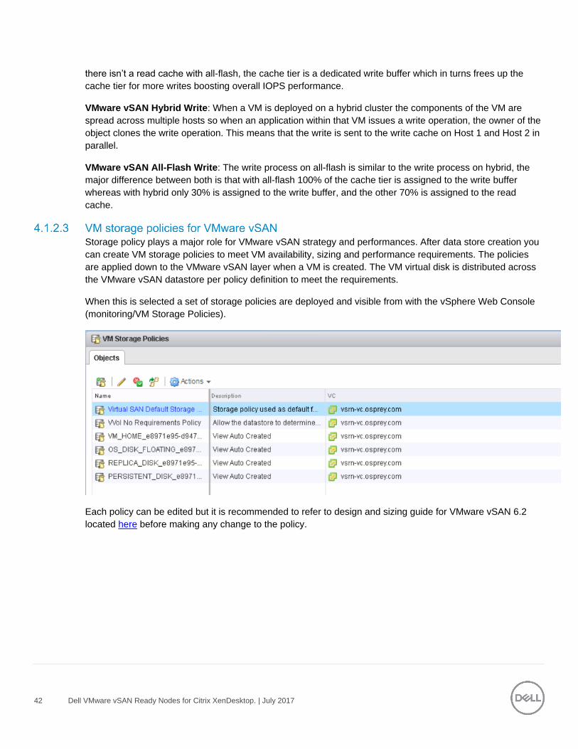
Storage policy plays a major role for VMware vSAN strategy and performances. After data store creation you
can create VM storage policies to meet VM availability, sizing and performance requirements. The policies
are applied down to the VMware vSAN layer when a VM is created. The VM virtual disk is distributed across
the VMware vSAN datastore per policy definition to meet the requirements.
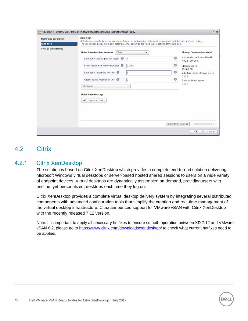
When this is selected a set of storage policies are deployed and visible from with the vSphere Web Console
(monitoring/VM Storage Policies).
Each policy can be edited but it is recommended to refer to design and sizing guide for VMware vSAN 6.2
located here before making any change to the policy.
43 Dell VMware vSAN Ready Nodes for Citrix XenDesktop. | July 2017
4.2 Citrix
The solution is based on Citrix XenDesktop which provides a complete end-to-end solution delivering
Microsoft Windows virtual desktops or server-based hosted shared sessions to users on a wide variety
of endpoint devices. Virtual desktops are dynamically assembled on demand, providing users with
pristine, yet personalized, desktops each time they log on.
Citrix XenDesktop provides a complete virtual desktop delivery system by integrating several distributed
components with advanced configuration tools that simplify the creation and real-time management of
the virtual desktop infrastructure. Citrix announced support for VMware vSAN with Citrix XenDesktop
with the recently released 7.12 version.
Note: It is important to apply all necessary hotfixes to ensure smooth operation between XD 7.12 and VMware
vSAN 6.2, please go to https://www.citrix.com/downloads/xendesktop/ to check what current hotfixes need to
be applied.
44 Dell VMware vSAN Ready Nodes for Citrix XenDesktop. | July 2017
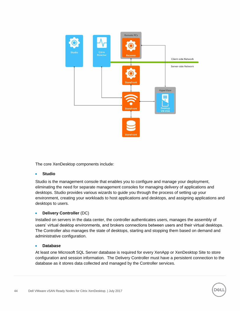
The core XenDesktop components include:
Studio
Studio is the management console that enables you to configure and manage your deployment,
eliminating the need for separate management consoles for managing delivery of applications and
desktops. Studio provides various wizards to guide you through the process of setting up your
environment, creating your workloads to host applications and desktops, and assigning applications and
desktops to users.
Delivery Controller (DC)
Installed on servers in the data center, the controller authenticates users, manages the assembly of
users’ virtual desktop environments, and brokers connections between users and their virtual desktops.
The Controller also manages the state of desktops, starting and stopping them based on demand and
administrative configuration.
Database
At least one Microsoft SQL Server database is required for every XenApp or XenDesktop Site to store
configuration and session information. The Delivery Controller must have a persistent connection to the
database as it stores data collected and managed by the Controller services.

45 Dell VMware vSAN Ready Nodes for Citrix XenDesktop. | July 2017
Director
Director is a web-based tool that enables IT support teams to monitor an environment, troubleshoot
issues before they become system-critical, and perform support tasks for end users. You can also view
and interact with a user's sessions using Microsoft Remote Assistance. Starting in version 7.12, Director
now includes detailed descriptions for connection and machine failures, one month historical data
(Enterprise edition), custom reporting, and notifications via SNMP traps.
Receiver
Installed on user devices, Citrix Receiver provides users with quick, secure, self-service access to
documents, applications, and desktops from any of the user's devices including smartphones, tablets,
and PCs. Receiver provides on-demand access to Windows, Web, and Software as a Service (SaaS)
applications. For devices that cannot install the Receiver software, Citrix Receiver for HTML5 provides
connectivity through a HTML5-compatible web browser.
StoreFront
StoreFront authenticates users to sites hosting resources and manages stores of desktops and applications
that user’s access. StoreFront version 3.8 (released with XenDesktop 7.12) and above includes ability to
create and use multiple IIS websites each having its own domain name.
License Server
The Citrix License Server is an essential component at any Citrix-based solution. Every Citrix product environment must
have at least one shared or dedicated license server. License servers are computers that are either partly or completely
dedicated to storing and managing licenses. Citrix products request licenses from a license server when users
attempt to connect.
Machine Creation Services (MCS)
A collection of services that work together to create virtual servers and desktops from a master image on
demand; optimizing storage utilization and providing a pristine virtual machine to users every time they log on.
Machine Creation Services is fully integrated and administrated in Citrix Studio.
Provisioning Services (PVS)
The Provisioning Services infrastructure is based on software-streaming technology. This technology allows
computers to be provisioned and re-provisioned in real-time from a single shared-disk image.
Virtual Delivery Agent (VDA)
The Virtual Desktop Agent is a transparent plugin that is installed on every virtual desktop or XenApp
host (RDSH) and enables the direct connection between the virtual desktop and users’ endpoint
devices. Windows and Linux VDAs are available.
46 Dell VMware vSAN Ready Nodes for Citrix XenDesktop. | July 2017
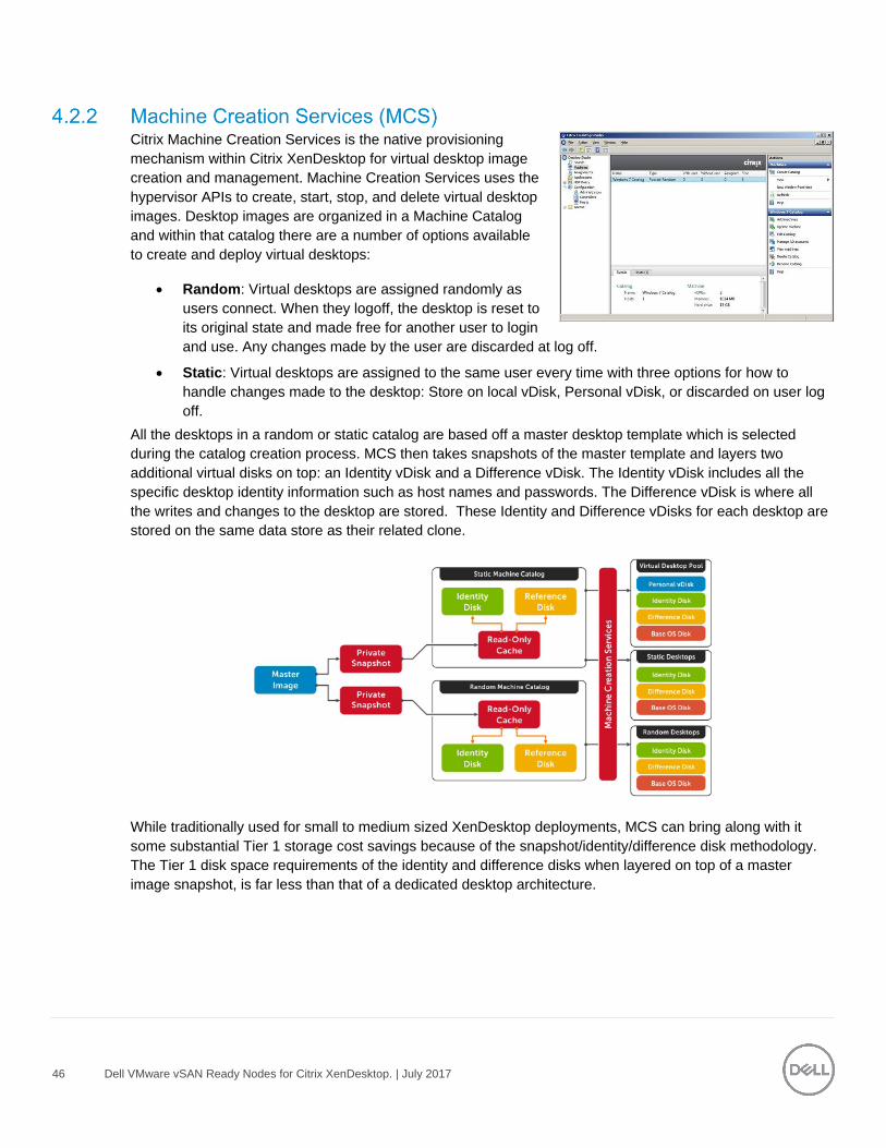
Citrix Machine Creation Services is the native provisioning
mechanism within Citrix XenDesktop for virtual desktop image
creation and management. Machine Creation Services uses the
hypervisor APIs to create, start, stop, and delete virtual desktop
images. Desktop images are organized in a Machine Catalog
and within that catalog there are a number of options available
to create and deploy virtual desktops:
Random: Virtual desktops are assigned randomly as
users connect. When they logoff, the desktop is reset to
its original state and made free for another user to login
and use. Any changes made by the user are discarded at log off.
Static: Virtual desktops are assigned to the same user every time with three options for how to
handle changes made to the desktop: Store on local vDisk, Personal vDisk, or discarded on user log
off.
All the desktops in a random or static catalog are based off a master desktop template which is selected
during the catalog creation process. MCS then takes snapshots of the master template and layers two
additional virtual disks on top: an Identity vDisk and a Difference vDisk. The Identity vDisk includes all the
specific desktop identity information such as host names and passwords. The Difference vDisk is where all
the writes and changes to the desktop are stored. These Identity and Difference vDisks for each desktop are
stored on the same data store as their related clone.
While traditionally used for small to medium sized XenDesktop deployments, MCS can bring along with it
some substantial Tier 1 storage cost savings because of the snapshot/identity/difference disk methodology.
The Tier 1 disk space requirements of the identity and difference disks when layered on top of a master
image snapshot, is far less than that of a dedicated desktop architecture.
47 Dell VMware vSAN Ready Nodes for Citrix XenDesktop. | July 2017
PVS is an alternative method of image provisioning which uses streaming to share a single base vDisk image instead of copying images to VMs. PVS are used to deliver shared vDisk images to physical or virtual machines. Another potential use is the serial provisioning of XenApp to enable scale-out hosted shared desktop infrastructure. Provisioning Services enables real-time streamed provisioning and re-provisioning which enable administrators to completely eliminate the need to manage and patch individual systems.
Desktop images are organized in a Machine Catalog and within that catalog there are a number of options available to create and deploy virtual or physical desktops:
Random: Virtual or physical desktops are assigned randomly as users connect. When they logoff, the
desktop is reset to its original state and made free for another user to login and use. Any changes
made by the user are discarded at log off.
Static: Virtual desktops are assigned to the same user every time with user changes stored on a
separate Personal vDisk.
Using Provisioning Services, vDisk images are configured in Standard Image mode, read-only, or Private
Image mode, read/write. A vDisk in Standard Image mode allows multiple desktops to boot from it simultaneously
greatly reducing the number of images that must be maintained and the amount of storage that is otherwise required
(non-persistent). Private Image mode vDisks are equivalent to dedicated hard disks and can only be used by one target
device at a time (persistent). The Provisioning Server runs on a virtual instance of Windows Server 2012 R2 or Windows
2016 on the Management Server(s).
Citrix Provisioning Services delivery of standard images relies on write-caches to store any writes made by the target OS. The most common write-cache implementation places write-cache on the target machine’s storage. Independent of the physical or virtual nature of the target machine, this storage has to be allocated and formatted to be usable.
While there are 4 possible locations for storage of the write cache in PVS, the Dell Wyse Datacenter solution recommends placement of the PVS write cache in the target compute host’s RAM with overflow enabled. We recommend using a cache size of 512MB for virtual desktops and 21GB for XenApp VMs delivered via PVS.
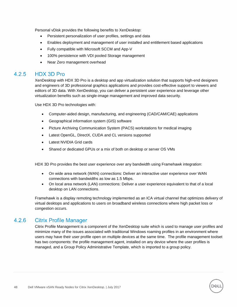
Citrix Personal vDisk is an enterprise workspace virtualization solution that is built into Citrix XenDesktop. Personal vDisk provides the user customization and personalization benefits of a persistent desktop image with the storage savings and performance of a single/shared image.
Used in conjunction with a static desktop experience, Citrix Personal vDisk allows each user to receive personal storage in the form of a layered vDisk (3GB minimum). This personal vDisk enables users to personalize and persist their desktop environment while providing storage for any user or departmental apps.
48 Dell VMware vSAN Ready Nodes for Citrix XenDesktop. | July 2017
Personal vDisk provides the following benefits to XenDesktop:
Persistent personalization of user profiles, settings and data
Enables deployment and management of user installed and entitlement based applications
Fully compatible with Microsoft SCCM and App-V
100% persistence with VDI pooled Storage management
Near Zero management overhead
XenDesktop with HDX 3D Pro is a desktop and app virtualization solution that supports high-end designers
and engineers of 3D professional graphics applications and provides cost-effective support to viewers and
editors of 3D data. With XenDesktop, you can deliver a persistent user experience and leverage other
virtualization benefits such as single-image management and improved data security.
Use HDX 3D Pro technologies with:
Computer-aided design, manufacturing, and engineering (CAD/CAM/CAE) applications
Geographical information system (GIS) software
Picture Archiving Communication System (PACS) workstations for medical imaging
Latest OpenGL, DirectX, CUDA and CL versions supported
Latest NVIDIA Grid cards
Shared or dedicated GPUs or a mix of both on desktop or server OS VMs
HDX 3D Pro provides the best user experience over any bandwidth using Framehawk integration:
On wide area network (WAN) connections: Deliver an interactive user experience over WAN
connections with bandwidths as low as 1.5 Mbps.
On local area network (LAN) connections: Deliver a user experience equivalent to that of a local
desktop on LAN connections.
Framehawk is a display remoting technology implemented as an ICA virtual channel that optimizes delivery of
virtual desktops and applications to users on broadband wireless connections where high packet loss or
congestion occurs.
Citrix Profile Management is a component of the XenDesktop suite which is used to manage user profiles and
minimize many of the issues associated with traditional Windows roaming profiles in an environment where
users may have their user profile open on multiple devices at the same time. The profile management toolset
has two components: the profile management agent, installed on any device where the user profiles is
managed, and a Group Policy Administrative Template, which is imported to a group policy.

49 Dell VMware vSAN Ready Nodes for Citrix XenDesktop. | July 2017
In order to further optimize, the profile management folders within the user profile is redirected the users’
home drive. The folder redirection is managed via group policy objects within Active Directory. The following
folders are redirected:
Contacts
Downloads
Favorites
Links
My Documents
Searches
Start Menu
Windows
My Music
My Pictures
My Videos
Desktop
Citrix XenApp 7.8 includes enhancements in the areas of faster access to virtual apps with higher connection
resiliency, improved graphics rendering, and new app-usage reporting and monitoring tools.
Citrix XenApp delivers Windows apps as secure mobile services. With XenApp, IT can mobilize the business -
increasing user productivity, while reducing costs by centralizing control and security of intellectual property.
XenApp delivers high-performance apps to any PC, Mac, laptop, tablet or smartphone that enable the delivery
of a native experience that is optimized for the type of device, as well as the network. XenApp is built on a 3rd
generation FlexCast Management Architecture (FMA) and is the only hybrid cloud-ready platform that
separates the management plane from the workload to enable IT to securely deliver published apps on-
premises, and manage workers and mobile workspaces either on-premises or in the cloud.
50 Dell VMware vSAN Ready Nodes for Citrix XenDesktop. | July 2017
Benefits of hosted desktop sessions and applications:
Management of applications (single instance)
Management of simple desktop images (no applications installed)
PVS to stream XenApp servers as well as user desktops
Scalability of XenDesktop compute hosts: CPU and IOPS reduction via application offload
Shared storage scalability: less IOPS = more room to grow
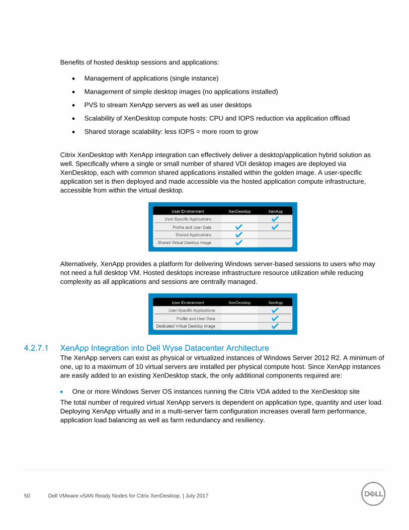
Citrix XenDesktop with XenApp integration can effectively deliver a desktop/application hybrid solution as
well. Specifically where a single or small number of shared VDI desktop images are deployed via
XenDesktop, each with common shared applications installed within the golden image. A user-specific
application set is then deployed and made accessible via the hosted application compute infrastructure,
accessible from within the virtual desktop.
Alternatively, XenApp provides a platform for delivering Windows server-based sessions to users who may
not need a full desktop VM. Hosted desktops increase infrastructure resource utilization while reducing
complexity as all applications and sessions are centrally managed.
The XenApp servers can exist as physical or virtualized instances of Windows Server 2012 R2. A minimum of
one, up to a maximum of 10 virtual servers are installed per physical compute host. Since XenApp instances
are easily added to an existing XenDesktop stack, the only additional components required are:
One or more Windows Server OS instances running the Citrix VDA added to the XenDesktop site
The total number of required virtual XenApp servers is dependent on application type, quantity and user load.
Deploying XenApp virtually and in a multi-server farm configuration increases overall farm performance,
application load balancing as well as farm redundancy and resiliency.

51 Dell VMware vSAN Ready Nodes for Citrix XenDesktop. | July 2017
In a XenDesktop implementation that leverages hosted applications, these execute from a centralized Windows Server and are then accessed via the Citrix Receiver. There are some instances, however, where certain departmental or custom applications cannot run using XenApp. At the same time for organizational policy or certain storage considerations, delivering these applications as a part of a base image is not possible either. In this case, Citrix Personal vDisk technology is the appropriate solution.
With Citrix Personal vDisk, each user of that single shared virtual desktop image also receives a personal layered vDisk, which enables the user to personalize their desktop and receive native application execution within a Windows client OS and not from a server. When leveraging the integration of XenApp within XenDesktop, all profile and user data is seamlessly accessed within both environments.
One of the many benefits of PVS is the ability to quickly scale the XenApp instances within a farm. Bandwidth is a key consideration and PVS bandwidth utilization is mostly a function of the number of target devices and the portion of the image(s) they utilize. Network impact considerations include:
● PVS streaming is delivered via UDP, yet the application has built-in mechanisms to provide flow control,
and retransmission as necessary.
● Data is streamed to each target device only as requested by the OS and applications running on the
target device. In most cases, less than 20% of any application is ever transferred.
● PVS relies on a cast of supporting infrastructure services. DNS and DHCP need to be provided on
dedicated service infrastructure servers, while TFTP and PXE Boot are functions that may be hosted on PVS
servers or elsewhere.
In XenApp and XenDesktop version 7.12 and above, the Local Host Cache (LHC) feature allows connection
brokering operations to continue when connectivity to the Site database has been interrupted. This includes
both failures between the Delivery Controller and Site database in on-premises deployments and when the
WAN link between the Site and Citrix control plane fails in a Citrix Cloud environment. LHC replaces the
connection leasing feature as the recommended XenApp and XenDesktop high availability solution. During
an outage, LHC will support new users and existing users launching new resources, as well as users
accessing pooled resources (shared desktops). Earlier versions of XenApp had a feature named Local Host
Cache but this is an entirely different implementation that is more robust and immune to corruption.
The following diagram shows the communication paths during normal operations. The principal broker on a
delivery controller accepts requests and communicates with the Site database to connect users. A check is
made every two minutes to determine if changes have been made to the principal broker’s configuration and if
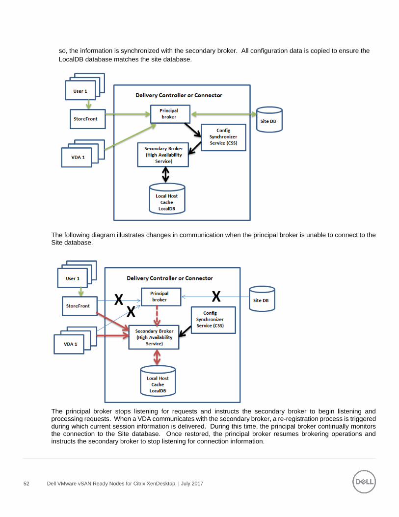
52 Dell VMware vSAN Ready Nodes for Citrix XenDesktop. | July 2017
so, the information is synchronized with the secondary broker. All configuration data is copied to ensure the
LocalDB database matches the site database.
The following diagram illustrates changes in communication when the principal broker is unable to connect to the Site database.
The principal broker stops listening for requests and instructs the secondary broker to begin listening and processing requests. When a VDA communicates with the secondary broker, a re-registration process is triggered during which current session information is delivered. During this time, the principal broker continually monitors the connection to the Site database. Once restored, the principal broker resumes brokering operations and instructs the secondary broker to stop listening for connection information.
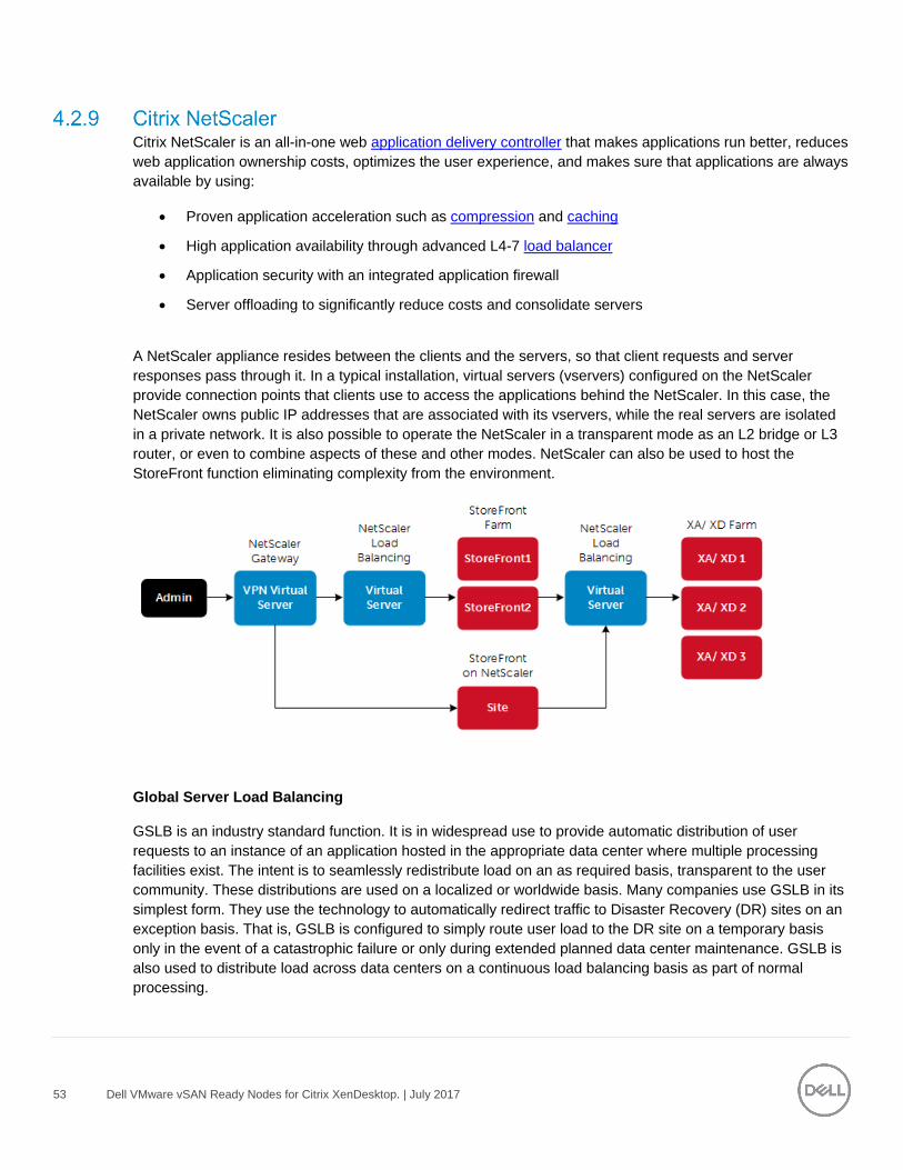
53 Dell VMware vSAN Ready Nodes for Citrix XenDesktop. | July 2017
Citrix NetScaler is an all-in-one web application delivery controller that makes applications run better, reduces
web application ownership costs, optimizes the user experience, and makes sure that applications are always
available by using:
Proven application acceleration such as compression and caching
High application availability through advanced L4-7 load balancer
Application security with an integrated application firewall
Server offloading to significantly reduce costs and consolidate servers
A NetScaler appliance resides between the clients and the servers, so that client requests and server
responses pass through it. In a typical installation, virtual servers (vservers) configured on the NetScaler
provide connection points that clients use to access the applications behind the NetScaler. In this case, the
NetScaler owns public IP addresses that are associated with its vservers, while the real servers are isolated
in a private network. It is also possible to operate the NetScaler in a transparent mode as an L2 bridge or L3
router, or even to combine aspects of these and other modes. NetScaler can also be used to host the
StoreFront function eliminating complexity from the environment.
Global Server Load Balancing
GSLB is an industry standard function. It is in widespread use to provide automatic distribution of user
requests to an instance of an application hosted in the appropriate data center where multiple processing
facilities exist. The intent is to seamlessly redistribute load on an as required basis, transparent to the user
community. These distributions are used on a localized or worldwide basis. Many companies use GSLB in its
simplest form. They use the technology to automatically redirect traffic to Disaster Recovery (DR) sites on an
exception basis. That is, GSLB is configured to simply route user load to the DR site on a temporary basis
only in the event of a catastrophic failure or only during extended planned data center maintenance. GSLB is
also used to distribute load across data centers on a continuous load balancing basis as part of normal
processing.
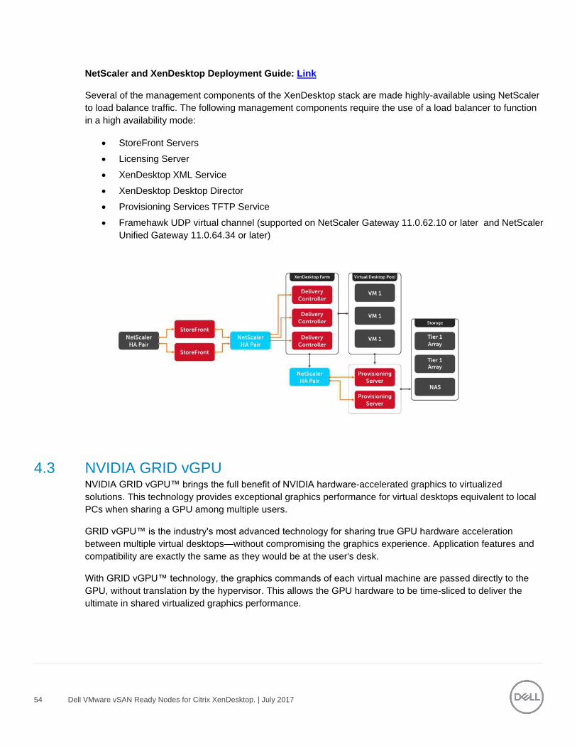
54 Dell VMware vSAN Ready Nodes for Citrix XenDesktop. | July 2017
NetScaler and XenDesktop Deployment Guide: Link
Several of the management components of the XenDesktop stack are made highly-available using NetScaler
to load balance traffic. The following management components require the use of a load balancer to function
in a high availability mode:
StoreFront Servers
Licensing Server
XenDesktop XML Service
XenDesktop Desktop Director
Provisioning Services TFTP Service
Framehawk UDP virtual channel (supported on NetScaler Gateway 11.0.62.10 or later and NetScaler
Unified Gateway 11.0.64.34 or later)
4.3 NVIDIA GRID vGPU NVIDIA GRID vGPU™ brings the full benefit of NVIDIA hardware-accelerated graphics to virtualized
solutions. This technology provides exceptional graphics performance for virtual desktops equivalent to local
PCs when sharing a GPU among multiple users.
GRID vGPU™ is the industry's most advanced technology for sharing true GPU hardware acceleration
between multiple virtual desktops—without compromising the graphics experience. Application features and
compatibility are exactly the same as they would be at the user's desk.
With GRID vGPU™ technology, the graphics commands of each virtual machine are passed directly to the
GPU, without translation by the hypervisor. This allows the GPU hardware to be time-sliced to deliver the
ultimate in shared virtualized graphics performance.
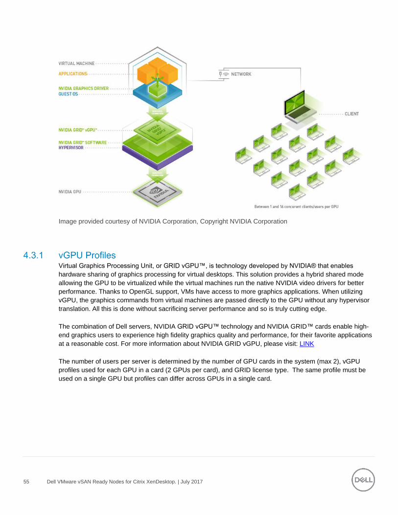
55 Dell VMware vSAN Ready Nodes for Citrix XenDesktop. | July 2017
Image provided courtesy of NVIDIA Corporation, Copyright NVIDIA Corporation
Virtual Graphics Processing Unit, or GRID vGPU™, is technology developed by NVIDIA® that enables
hardware sharing of graphics processing for virtual desktops. This solution provides a hybrid shared mode
allowing the GPU to be virtualized while the virtual machines run the native NVIDIA video drivers for better
performance. Thanks to OpenGL support, VMs have access to more graphics applications. When utilizing
vGPU, the graphics commands from virtual machines are passed directly to the GPU without any hypervisor
translation. All this is done without sacrificing server performance and so is truly cutting edge.
The combination of Dell servers, NVIDIA GRID vGPU™ technology and NVIDIA GRID™ cards enable high-
end graphics users to experience high fidelity graphics quality and performance, for their favorite applications
at a reasonable cost. For more information about NVIDIA GRID vGPU, please visit: LINK
The number of users per server is determined by the number of GPU cards in the system (max 2), vGPU
profiles used for each GPU in a card (2 GPUs per card), and GRID license type. The same profile must be
used on a single GPU but profiles can differ across GPUs in a single card.
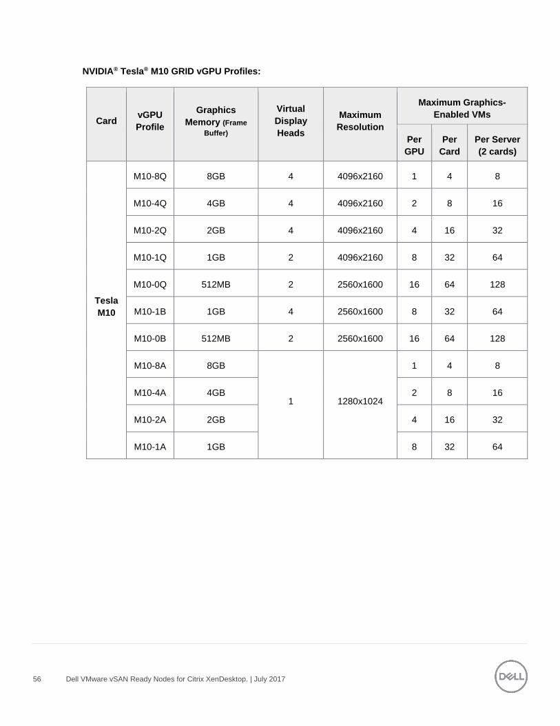
56 Dell VMware vSAN Ready Nodes for Citrix XenDesktop. | July 2017
NVIDIA® Tesla® M10 GRID vGPU Profiles:
Card vGPU
Profile
Graphics
Memory (Frame
Buffer)
Virtual
Display
Heads
Maximum
Resolution
Maximum Graphics-
Enabled VMs
Per
GPU
Per
Card
Per Server
(2 cards)
64bit Linux
Tesla
M10
M10-8Q 8GB 4 4096x2160 1 4 8
∞ M10-4Q 4GB 4 4096x2160 2 8 16
M10-2Q 2GB 4 4096x2160 4 16 32
M10-1Q 1GB 2 4096x2160 8 32 64
M10-0Q 512MB 2 2560x1600 16 64 128
M10-1B 1GB 4 2560x1600 8 32 64
M10-0B 512MB 2 2560x1600 16 64 128
M10-8A 8GB
1 1280x1024
1 4 8
M10-4A 4GB 2 8 16
M10-2A 2GB 4 16 32
M10-1A 1GB 8 32 64
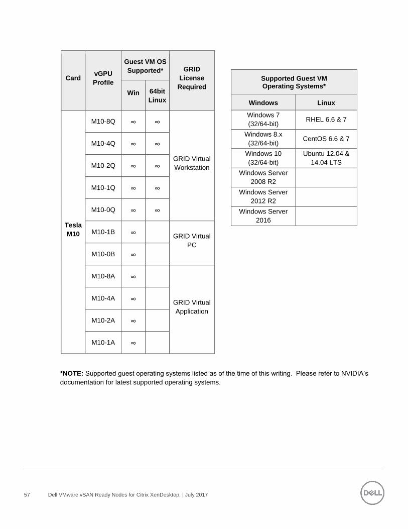
57 Dell VMware vSAN Ready Nodes for Citrix XenDesktop. | July 2017
*NOTE: Supported guest operating systems listed as of the time of this writing. Please refer to NVIDIA’s
documentation for latest supported operating systems.
Card vGPU
Profile
Guest VM OS
Supported* GRID
License
Required Win 64bit
Linux
Tesla
M10
M10-8Q ∞ ∞
GRID Virtual
Workstation
M10-4Q ∞ ∞
M10-2Q ∞ ∞
M10-1Q ∞ ∞
M10-0Q ∞ ∞
M10-1B ∞ GRID Virtual
PC
M10-0B ∞
M10-8A ∞
GRID Virtual
Application
M10-4A ∞
M10-2A ∞
M10-1A ∞
Supported Guest VM Operating Systems*
Windows Linux
Windows 7
(32/64-bit) RHEL 6.6 & 7
Windows 8.x
(32/64-bit) CentOS 6.6 & 7
Windows 10
(32/64-bit)
Ubuntu 12.04 &
14.04 LTS
Windows Server
2008 R2
Windows Server
2012 R2
Windows Server
2016
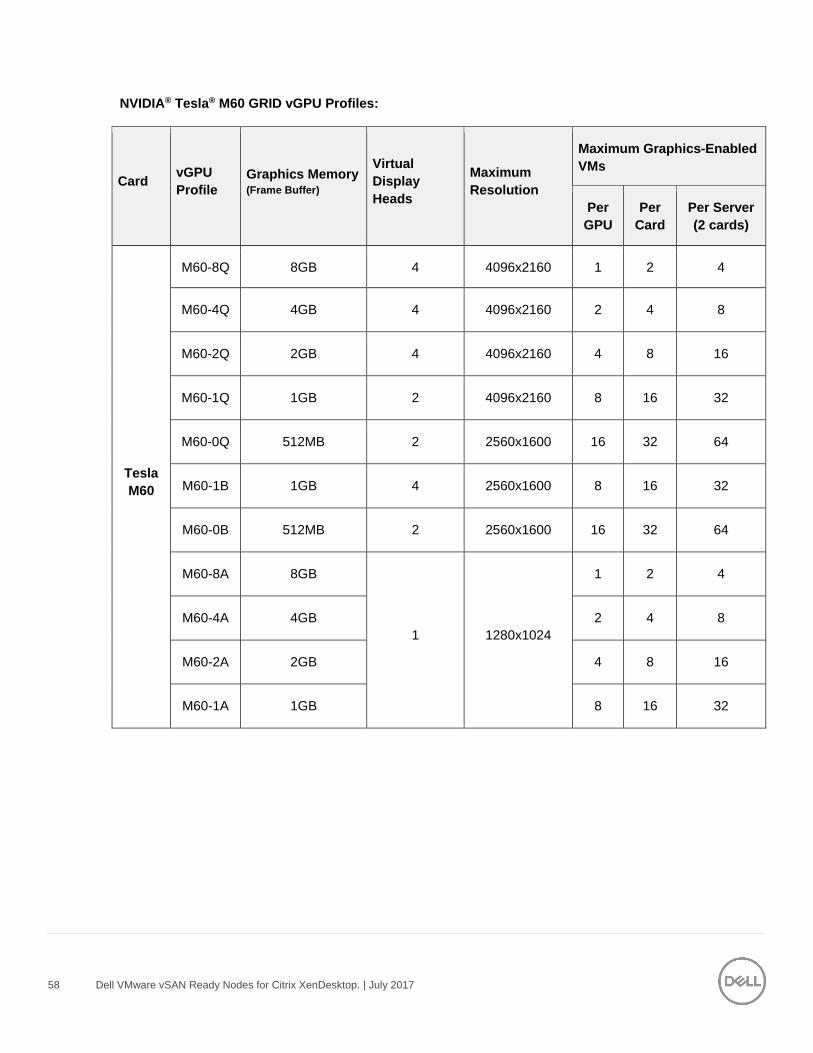
58 Dell VMware vSAN Ready Nodes for Citrix XenDesktop. | July 2017
NVIDIA® Tesla® M60 GRID vGPU Profiles:
Card vGPU
Profile
Graphics Memory (Frame Buffer)
Virtual
Display
Heads
Maximum
Resolution
Maximum Graphics-Enabled
VMs
Per
GPU
Per
Card
Per Server
(2 cards)
64bit Linux
Tesla
M60
M60-8Q 8GB 4 4096x2160 1 2 4
∞ M60-4Q 4GB 4 4096x2160 2 4 8
∞ M60-2Q 2GB 4 4096x2160 4 8 16
∞ M60-1Q 1GB 2 4096x2160 8 16 32
∞ M60-0Q 512MB 2 2560x1600 16 32 64
∞ M60-1B 1GB 4 2560x1600 8 16 32
M60-0B 512MB 2 2560x1600 16 32 64
M60-8A 8GB
1 1280x1024
1 2 4
M60-4A 4GB 2 4 8
M60-2A 2GB 4 8 16
M60-1A 1GB 8 16 32
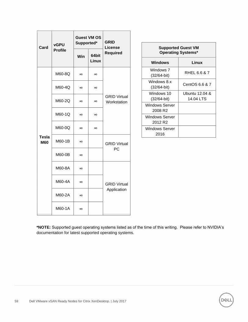
59 Dell VMware vSAN Ready Nodes for Citrix XenDesktop. | July 2017
*NOTE: Supported guest operating systems listed as of the time of this writing. Please refer to NVIDIA’s
documentation for latest supported operating systems.
Card vGPU
Profile
Guest VM OS
Supported* GRID
License
Required Win 64bit
Linux
Tesla
M60
M60-8Q ∞ ∞
GRID Virtual
Workstation
M60-4Q ∞ ∞
M60-2Q ∞ ∞
M60-1Q ∞ ∞
M60-0Q ∞ ∞
M60-1B ∞ GRID Virtual
PC
M60-0B ∞
M60-8A ∞
GRID Virtual
Application
M60-4A ∞
M60-2A ∞
M60-1A ∞
Supported Guest VM Operating Systems*
Windows Linux
Windows 7
(32/64-bit) RHEL 6.6 & 7
Windows 8.x
(32/64-bit) CentOS 6.6 & 7
Windows 10
(32/64-bit)
Ubuntu 12.04 &
14.04 LTS
Windows Server
2008 R2
Windows Server
2012 R2
Windows Server
2016
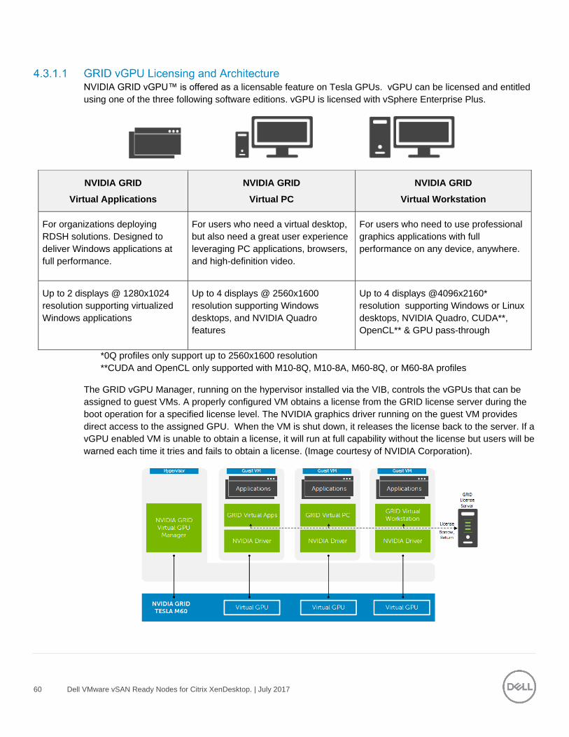
60 Dell VMware vSAN Ready Nodes for Citrix XenDesktop. | July 2017
NVIDIA GRID vGPU™ is offered as a licensable feature on Tesla GPUs. vGPU can be licensed and entitled
using one of the three following software editions. vGPU is licensed with vSphere Enterprise Plus.
NVIDIA GRID
Virtual Applications
NVIDIA GRID
Virtual PC
NVIDIA GRID
Virtual Workstation
For organizations deploying
RDSH solutions. Designed to
deliver Windows applications at
full performance.
For users who need a virtual desktop,
but also need a great user experience
leveraging PC applications, browsers,
and high-definition video.
For users who need to use professional
graphics applications with full
performance on any device, anywhere.
Up to 2 displays @ 1280x1024
resolution supporting virtualized
Windows applications
Up to 4 displays @ 2560x1600
resolution supporting Windows
desktops, and NVIDIA Quadro
features
Up to 4 displays @4096x2160*
resolution supporting Windows or Linux
desktops, NVIDIA Quadro, CUDA**,
OpenCL** & GPU pass-through
*0Q profiles only support up to 2560x1600 resolution
**CUDA and OpenCL only supported with M10-8Q, M10-8A, M60-8Q, or M60-8A profiles
The GRID vGPU Manager, running on the hypervisor installed via the VIB, controls the vGPUs that can be
assigned to guest VMs. A properly configured VM obtains a license from the GRID license server during the
boot operation for a specified license level. The NVIDIA graphics driver running on the guest VM provides
direct access to the assigned GPU. When the VM is shut down, it releases the license back to the server. If a
vGPU enabled VM is unable to obtain a license, it will run at full capability without the license but users will be
warned each time it tries and fails to obtain a license. (Image courtesy of NVIDIA Corporation).

61 Dell VMware vSAN Ready Nodes for Citrix XenDesktop. | July 2017
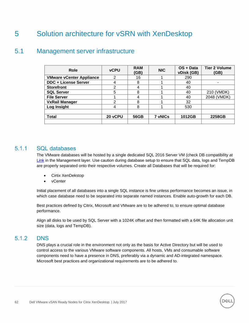
62 Dell VMware vSAN Ready Nodes for Citrix XenDesktop. | July 2017
5 Solution architecture for vSRN with XenDesktop
5.1 Management server infrastructure
Role vCPU RAM (GB)
NIC OS + Data vDisk (GB)
Tier 2 Volume (GB)
VMware vCenter Appliance 2 16 1 290
DDC + License Server 4 8 1 40 -
Storefront 2 4 1 40
SQL Server 5 8 1 40 210 (VMDK)
File Server 1 4 1 40 2048 (VMDK)
VxRail Manager 2 8 1 32
Log Insight 4 8 1 530
Total 20 vCPU 56GB 7 vNICs 1012GB 2258GB
The VMware databases will be hosted by a single dedicated SQL 2016 Server VM (check DB compatibility at
Link in the Management layer. Use caution during database setup to ensure that SQL data, logs and TempDB
are properly separated onto their respective volumes. Create all Databases that will be required for:
Cirtix XenDekstop
vCenter
Initial placement of all databases into a single SQL instance is fine unless performance becomes an issue, in
which case database need to be separated into separate named instances. Enable auto-growth for each DB.
Best practices defined by Citrix, Microsoft and VMware are to be adhered to, to ensure optimal database
performance.
Align all disks to be used by SQL Server with a 1024K offset and then formatted with a 64K file allocation unit
size (data, logs and TempDB).
DNS plays a crucial role in the environment not only as the basis for Active Directory but will be used to
control access to the various VMware software components. All hosts, VMs and consumable software
components need to have a presence in DNS, preferably via a dynamic and AD-integrated namespace.
Microsoft best practices and organizational requirements are to be adhered to.
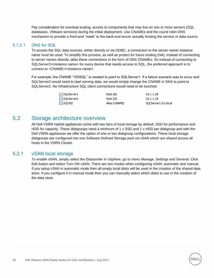
63 Dell VMware vSAN Ready Nodes for Citrix XenDesktop. | July 2017
Pay consideration for eventual scaling, access to components that may live on one or more servers (SQL
databases, VMware services) during the initial deployment. Use CNAMEs and the round robin DNS
mechanism to provide a front-end “mask” to the back-end server actually hosting the service or data source.
To access the SQL data sources, either directly or via ODBC, a connection to the server name\ instance
name must be used. To simplify this process, as well as protect for future scaling (HA), instead of connecting
to server names directly, alias these connections in the form of DNS CNAMEs. So instead of connecting to
SQLServer1\<instance name> for every device that needs access to SQL, the preferred approach is to
connect to <CNAME>\<instance name>.
For example, the CNAME “VDISQL” is created to point to SQLServer1. If a failure scenario was to occur and
SQLServer2 would need to start serving data, we would simply change the CNAME in DNS to point to
SQLServer2. No infrastructure SQL client connections would need to be touched.
5.2 Storage architecture overview All Dell VSRN Hybrid appliances come with two tiers of local storage by default, SSD for performance and
HDD for capacity. These diskgroups need a minimum of 1 x SSD and 1 x HDD per diskgroup and with the
Dell VSRN appliances we offer the option of one or two diskgroup configurations. These local storage
diskgroups are configured into one Software Defined Storage pool via vSAN which are shared across all
hosts in the VSRN Cluster.
To enable vSAN, simply select the Datacenter in vSphere, go to menu Manage, Settings and General. Click
Edit button and select Turn ON vSAN. There are two modes when configuring vSAN: automatic and manual.
If you setup vSAN in automatic mode then all empty local disks will be used in the creation of the shared data
store. If you configure it in manual mode then you can manually select which disks to use in the creation of
the data store.

64 Dell VMware vSAN Ready Nodes for Citrix XenDesktop. | July 2017
5.3 Virtual networking
The network configuration for the Dell vSRN appliances utilizes a 10Gb converged infrastructure model. The
management, vMotion, VDI traffic and vSAN are configured across 2 x 10Gb NICs configured in an
active/active team and the traffics is separated out via VLAN. When deploying larger cluster configurations it
may be optimal to split out the management and vSAN traffic. The Server configurations are equipped with 4
x 10GB connections to facilitate this
The network configuration in this model is the same for the compute and management layer. They both share
the local storage vSAN configuration taking advantage of HA including Live Migrations. The following outlines
the VLAN requirements for the Compute and Management hosts in this solution model:
VSRN VLAN configuration
o Management VLAN: Configured for hypervisor infrastructure traffic – L3 routed via core
switch
o VDI VLAN: Configured for VDI session traffic – L3 routed via core switch
o vSAN VLAN: Configured for vSAN traffic – L2 switched only via ToR switch
o vMotion VLAN: Configured for Live Migration traffic – L2 switched only, trunked from Core
(HA only)
o VDI Management VLAN: Configured for VDI infrastructure traffic – L3 routed via core switch
A VLAN for iDRAC is configured for all hardware management traffic – L3 routed via core switch
This traffic is combined within a single switch in smaller stacks to minimize the initial investment; however,
VLANs are required for each traffic type to enable traffic separation. Each vSAN host will have a quad port
NDC which includes 4 x 10Gb interfaces and the 2 free 10Gb interfaces can be used to separate out the
vSAN traffic for larger clusters, configure the LAN traffic from the server to the ToR switch as a LAG.
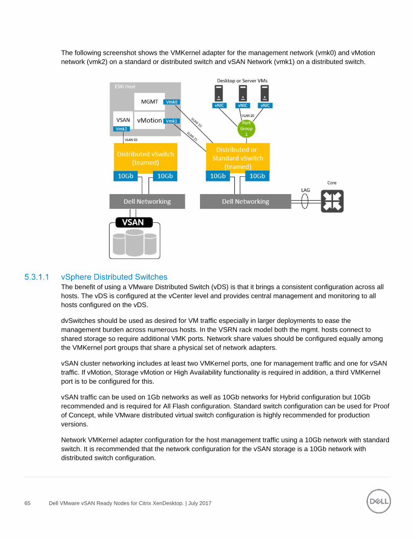
65 Dell VMware vSAN Ready Nodes for Citrix XenDesktop. | July 2017
The following screenshot shows the VMKernel adapter for the management network (vmk0) and vMotion
network (vmk2) on a standard or distributed switch and vSAN Network (vmk1) on a distributed switch.
The benefit of using a VMware Distributed Switch (vDS) is that it brings a consistent configuration across all
hosts. The vDS is configured at the vCenter level and provides central management and monitoring to all
hosts configured on the vDS.
dvSwitches should be used as desired for VM traffic especially in larger deployments to ease the
management burden across numerous hosts. In the VSRN rack model both the mgmt. hosts connect to
shared storage so require additional VMK ports. Network share values should be configured equally among
the VMKernel port groups that share a physical set of network adapters.
vSAN cluster networking includes at least two VMKernel ports, one for management traffic and one for vSAN
traffic. If vMotion, Storage vMotion or High Availability functionality is required in addition, a third VMKernel
port is to be configured for this.
vSAN traffic can be used on 1Gb networks as well as 10Gb networks for Hybrid configuration but 10Gb
recommended and is required for All Flash configuration. Standard switch configuration can be used for Proof
of Concept, while VMware distributed virtual switch configuration is highly recommended for production
versions.
Network VMKernel adapter configuration for the host management traffic using a 10Gb network with standard
switch. It is recommended that the network configuration for the vSAN storage is a 10Gb network with
distributed switch configuration.
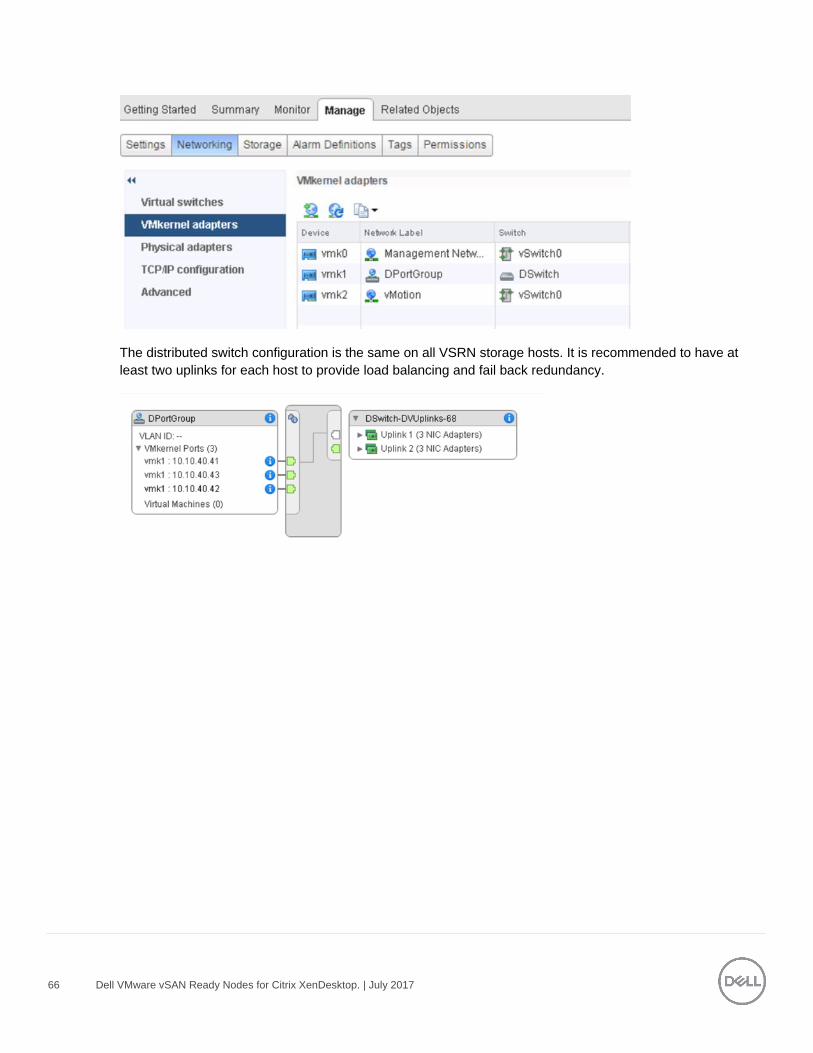
66 Dell VMware vSAN Ready Nodes for Citrix XenDesktop. | July 2017
The distributed switch configuration is the same on all VSRN storage hosts. It is recommended to have at
least two uplinks for each host to provide load balancing and fail back redundancy.
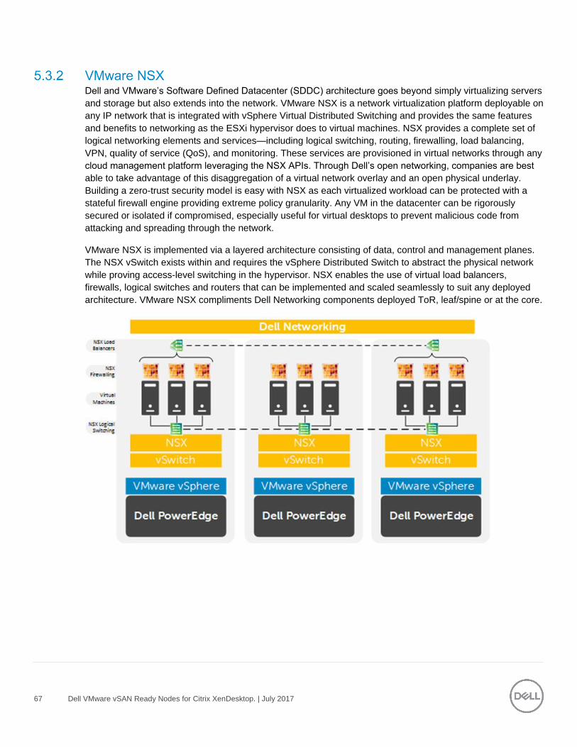
67 Dell VMware vSAN Ready Nodes for Citrix XenDesktop. | July 2017
Dell and VMware’s Software Defined Datacenter (SDDC) architecture goes beyond simply virtualizing servers
and storage but also extends into the network. VMware NSX is a network virtualization platform deployable on
any IP network that is integrated with vSphere Virtual Distributed Switching and provides the same features
and benefits to networking as the ESXi hypervisor does to virtual machines. NSX provides a complete set of
logical networking elements and services—including logical switching, routing, firewalling, load balancing,
VPN, quality of service (QoS), and monitoring. These services are provisioned in virtual networks through any
cloud management platform leveraging the NSX APIs. Through Dell’s open networking, companies are best
able to take advantage of this disaggregation of a virtual network overlay and an open physical underlay.
Building a zero-trust security model is easy with NSX as each virtualized workload can be protected with a
stateful firewall engine providing extreme policy granularity. Any VM in the datacenter can be rigorously
secured or isolated if compromised, especially useful for virtual desktops to prevent malicious code from
attacking and spreading through the network.
VMware NSX is implemented via a layered architecture consisting of data, control and management planes.
The NSX vSwitch exists within and requires the vSphere Distributed Switch to abstract the physical network
while proving access-level switching in the hypervisor. NSX enables the use of virtual load balancers,
firewalls, logical switches and routers that can be implemented and scaled seamlessly to suit any deployed
architecture. VMware NSX compliments Dell Networking components deployed ToR, leaf/spine or at the core.
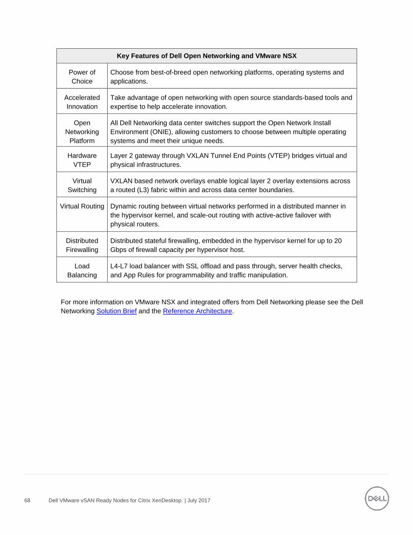
68 Dell VMware vSAN Ready Nodes for Citrix XenDesktop. | July 2017
Key Features of Dell Open Networking and VMware NSX
Power of
Choice Choose from best-of-breed open networking platforms, operating systems and
applications.
Accelerated
Innovation
Take advantage of open networking with open source standards-based tools and
expertise to help accelerate innovation.
Open
Networking
Platform
All Dell Networking data center switches support the Open Network Install
Environment (ONIE), allowing customers to choose between multiple operating
systems and meet their unique needs.
Hardware
VTEP
Gateway
Layer 2 gateway through VXLAN Tunnel End Points (VTEP) bridges virtual and
physical infrastructures.
Virtual
Switching
VXLAN based network overlays enable logical layer 2 overlay extensions across
a routed (L3) fabric within and across data center boundaries.
Virtual Routing Dynamic routing between virtual networks performed in a distributed manner in
the hypervisor kernel, and scale-out routing with active-active failover with
physical routers.
Distributed
Firewalling
Distributed stateful firewalling, embedded in the hypervisor kernel for up to 20
Gbps of firewall capacity per hypervisor host.
Load
Balancing
L4-L7 load balancer with SSL offload and pass through, server health checks,
and App Rules for programmability and traffic manipulation.
For more information on VMware NSX and integrated offers from Dell Networking please see the Dell
Networking Solution Brief and the Reference Architecture.
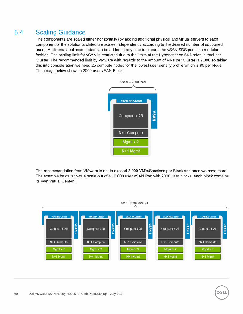
69 Dell VMware vSAN Ready Nodes for Citrix XenDesktop. | July 2017
5.4 Scaling Guidance The components are scaled either horizontally (by adding additional physical and virtual servers to each
component of the solution architecture scales independently according to the desired number of supported
users. Additional appliance nodes can be added at any time to expand the vSAN SDS pool in a modular
fashion. The scaling limit for vSAN is restricted due to the limits of the Hypervisor so 64 Nodes in total per
Cluster. The recommended limit by VMware with regards to the amount of VMs per Cluster is 2,000 so taking
this into consideration we need 25 compute nodes for the lowest user density profile which is 80 per Node.
The image below shows a 2000 user vSAN Block.
The recommendation from VMware is not to exceed 2,000 VM’s/Sessions per Block and once we have more
The example below shows a scale out of a 10,000 user vSAN Pod with 2000 user blocks, each block contains
its own Virtual Center.
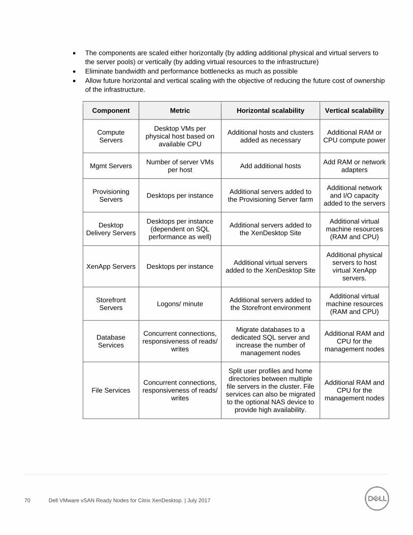
70 Dell VMware vSAN Ready Nodes for Citrix XenDesktop. | July 2017
The components are scaled either horizontally (by adding additional physical and virtual servers to
the server pools) or vertically (by adding virtual resources to the infrastructure)
Eliminate bandwidth and performance bottlenecks as much as possible
Allow future horizontal and vertical scaling with the objective of reducing the future cost of ownership
of the infrastructure.
Component Metric Horizontal scalability Vertical scalability
Compute Servers
Desktop VMs per physical host based on
available CPU
Additional hosts and clusters added as necessary
Additional RAM or CPU compute power
Mgmt Servers Number of server VMs
per host Add additional hosts
Add RAM or network adapters
Provisioning Servers
Desktops per instance Additional servers added to the Provisioning Server farm
Additional network and I/O capacity
added to the servers
Desktop Delivery Servers
Desktops per instance (dependent on SQL performance as well)
Additional servers added to the XenDesktop Site
Additional virtual machine resources
(RAM and CPU)
XenApp Servers Desktops per instance Additional virtual servers
added to the XenDesktop Site
Additional physical servers to host virtual XenApp
servers.
Storefront Servers
Logons/ minute Additional servers added to the Storefront environment
Additional virtual machine resources
(RAM and CPU)
Database Services
Concurrent connections, responsiveness of reads/
writes
Migrate databases to a dedicated SQL server and
increase the number of management nodes
Additional RAM and CPU for the
management nodes
File Services Concurrent connections, responsiveness of reads/
writes
Split user profiles and home directories between multiple file servers in the cluster. File services can also be migrated to the optional NAS device to
provide high availability.
Additional RAM and CPU for the
management nodes
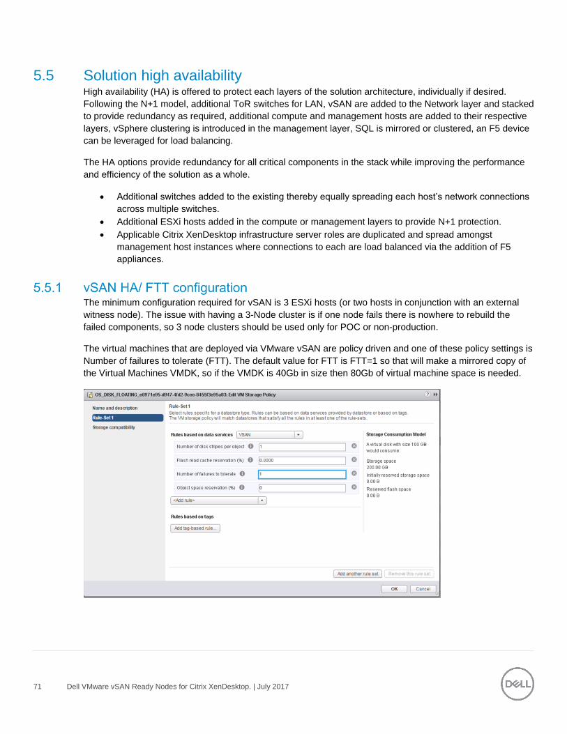
71 Dell VMware vSAN Ready Nodes for Citrix XenDesktop. | July 2017
5.5 Solution high availability High availability (HA) is offered to protect each layers of the solution architecture, individually if desired.
Following the N+1 model, additional ToR switches for LAN, vSAN are added to the Network layer and stacked
to provide redundancy as required, additional compute and management hosts are added to their respective
layers, vSphere clustering is introduced in the management layer, SQL is mirrored or clustered, an F5 device
can be leveraged for load balancing.
The HA options provide redundancy for all critical components in the stack while improving the performance
and efficiency of the solution as a whole.
Additional switches added to the existing thereby equally spreading each host’s network connections
across multiple switches.
Additional ESXi hosts added in the compute or management layers to provide N+1 protection.
Applicable Citrix XenDesktop infrastructure server roles are duplicated and spread amongst
management host instances where connections to each are load balanced via the addition of F5
appliances.
The minimum configuration required for vSAN is 3 ESXi hosts (or two hosts in conjunction with an external
witness node). The issue with having a 3-Node cluster is if one node fails there is nowhere to rebuild the
failed components, so 3 node clusters should be used only for POC or non-production.
The virtual machines that are deployed via VMware vSAN are policy driven and one of these policy settings is
Number of failures to tolerate (FTT). The default value for FTT is FTT=1 so that will make a mirrored copy of
the Virtual Machines VMDK, so if the VMDK is 40Gb in size then 80Gb of virtual machine space is needed.
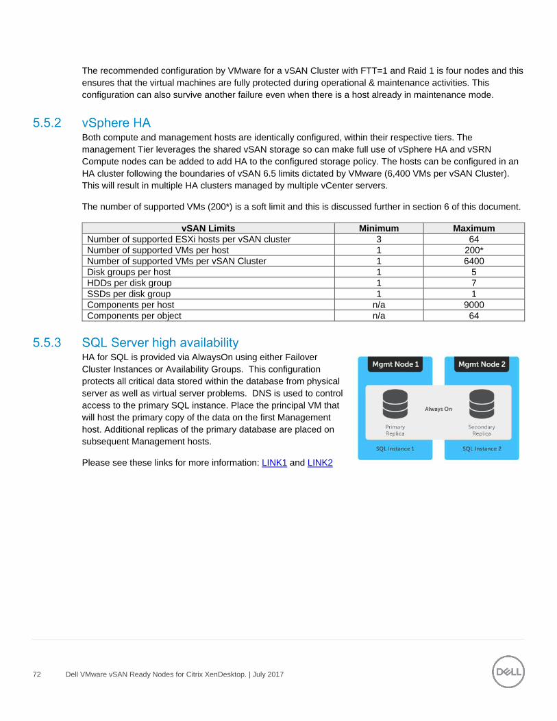
72 Dell VMware vSAN Ready Nodes for Citrix XenDesktop. | July 2017
The recommended configuration by VMware for a vSAN Cluster with FTT=1 and Raid 1 is four nodes and this
ensures that the virtual machines are fully protected during operational & maintenance activities. This
configuration can also survive another failure even when there is a host already in maintenance mode.
Both compute and management hosts are identically configured, within their respective tiers. The
management Tier leverages the shared vSAN storage so can make full use of vSphere HA and vSRN
Compute nodes can be added to add HA to the configured storage policy. The hosts can be configured in an
HA cluster following the boundaries of vSAN 6.5 limits dictated by VMware (6,400 VMs per vSAN Cluster).
This will result in multiple HA clusters managed by multiple vCenter servers.
The number of supported VMs (200*) is a soft limit and this is discussed further in section 6 of this document.
vSAN Limits Minimum Maximum
Number of supported ESXi hosts per vSAN cluster 3 64
Number of supported VMs per host 1 200*
Number of supported VMs per vSAN Cluster 1 6400
Disk groups per host 1 5
HDDs per disk group 1 7
SSDs per disk group 1 1
Components per host n/a 9000
Components per object n/a 64
HA for SQL is provided via AlwaysOn using either Failover
Cluster Instances or Availability Groups. This configuration
protects all critical data stored within the database from physical
server as well as virtual server problems. DNS is used to control
access to the primary SQL instance. Place the principal VM that
will host the primary copy of the data on the first Management
host. Additional replicas of the primary database are placed on
subsequent Management hosts.
Please see these links for more information: LINK1 and LINK2
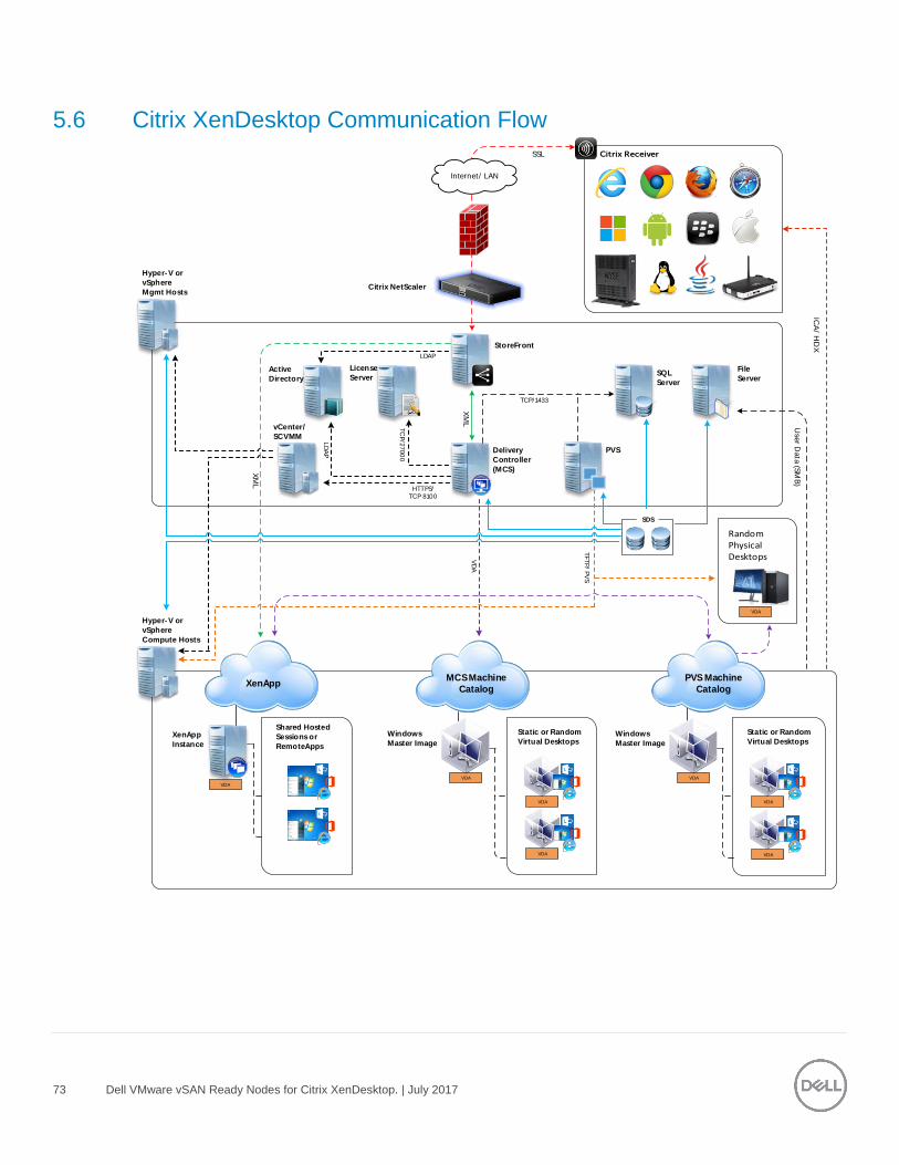
73 Dell VMware vSAN Ready Nodes for Citrix XenDesktop. | July 2017
5.6 Citrix XenDesktop Communication Flow
Hyper-V or
vSphere
Compute Hosts
Windows
Master Image
Delivery
Controller
(MCS)
SSL
File
Server
Citrix NetScaler
License
Server
StoreFront
Internet / LAN
Use
r Data (S
MB
)
LD
AP
MCS Machine
Catalog
XenApp
Instance
XM
L
SQL
Server
Active
Directory
VDA
Shared Hosted
Sessions or
RemoteApps
SDS
PVS
TC
P/2
700
0
TCP/1433
vCenter/
SCVMM
XM
L HTTPS/
TCP 8100
ICA
/ HD
X
VD
A
LDAP
XenApp PVS Machine
Catalog
VDA
VDA
TFTP
/ PV
S
VDA
Static or Random
Virtual Desktops
VDA
VDA
Windows
Master Image
VDA
VDA
Static or Random
Virtual Desktops
Hyper-V or
vSphere
Mgmt Hosts
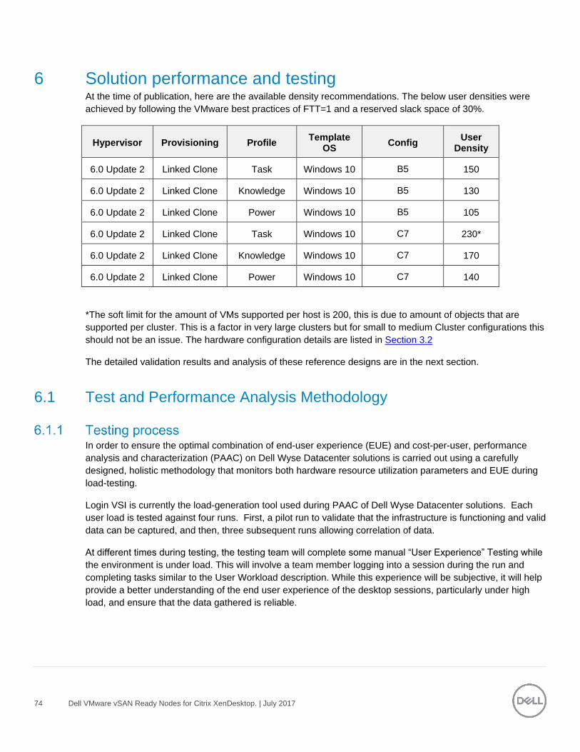
74 Dell VMware vSAN Ready Nodes for Citrix XenDesktop. | July 2017
6 Solution performance and testing At the time of publication, here are the available density recommendations. The below user densities were
achieved by following the VMware best practices of FTT=1 and a reserved slack space of 30%.
Hypervisor Provisioning Profile Template
OS Config
User Density
6.0 Update 2 Linked Clone Task Windows 10 B5 150
6.0 Update 2 Linked Clone Knowledge Windows 10 B5 130
6.0 Update 2 Linked Clone Power Windows 10 B5 105
6.0 Update 2 Linked Clone Task Windows 10 C7 230*
6.0 Update 2 Linked Clone Knowledge Windows 10 C7 170
6.0 Update 2 Linked Clone Power Windows 10 C7 140
*The soft limit for the amount of VMs supported per host is 200, this is due to amount of objects that are
supported per cluster. This is a factor in very large clusters but for small to medium Cluster configurations this
should not be an issue. The hardware configuration details are listed in Section 3.2
The detailed validation results and analysis of these reference designs are in the next section.
6.1 Test and Performance Analysis Methodology
In order to ensure the optimal combination of end-user experience (EUE) and cost-per-user, performance
analysis and characterization (PAAC) on Dell Wyse Datacenter solutions is carried out using a carefully
designed, holistic methodology that monitors both hardware resource utilization parameters and EUE during
load-testing.
Login VSI is currently the load-generation tool used during PAAC of Dell Wyse Datacenter solutions. Each
user load is tested against four runs. First, a pilot run to validate that the infrastructure is functioning and valid
data can be captured, and then, three subsequent runs allowing correlation of data.
At different times during testing, the testing team will complete some manual “User Experience” Testing while
the environment is under load. This will involve a team member logging into a session during the run and
completing tasks similar to the User Workload description. While this experience will be subjective, it will help
provide a better understanding of the end user experience of the desktop sessions, particularly under high
load, and ensure that the data gathered is reliable.
75 Dell VMware vSAN Ready Nodes for Citrix XenDesktop. | July 2017
Login VSI by Login Consultants is the de-facto industry standard tool for testing VDI environments and server-
based computing (RDSH environments). It installs a standard collection of desktop application software (e.g.
Microsoft Office, Adobe Acrobat Reader) on each VDI desktop; it then uses launcher systems to connect a
specified number of users to available desktops within the environment. Once the user is connected, the
workload is started via a logon script which starts the test script once the user environment is configured by
the login script. Each launcher system can launch connections to a number of ‘target’ machines (i.e. VDI
desktops). The launchers and Login VSI environment are configured and managed by a centralized
management console.
Additionally, the following login and boot paradigm is used:
Users are logged in within a login timeframe of 1 hour. Exception to this login timeframe occurs when
testing low density solutions such as GPU/graphics based configurations.
All desktops are pre-booted in advance of logins commencing.
All desktops run an industry-standard anti-virus solution. Windows Defender is used for Windows 10
due to issues implementing McAfee.
It’s important to understand user workloads and profiles when designing a desktop virtualization solution in
order to understand the density numbers that the solution can support. At Dell, we use five workload / profile
levels, each of which is bound by specific metrics and capabilities with two targeted at graphics-intensive use
cases. We will present more detailed information in relation to these workloads and profiles below but first it is
useful to define the terms “profile” and “workload” as they are used in this document.
Profile: This is the configuration of the virtual desktop - number of vCPUs and amount of RAM
configured on the desktop (i.e. available to the user).
Workload: This is the set of applications used by performance analysis and characterization (PAAC)
of Dell Wyse Datacenter solutions (e.g. Microsoft Office applications, PDF Reader, Internet Explorer
etc.)
Load-testing on each profile is carried out using an appropriate workload that is representative of the relevant
use case and summarized in the table below:
Profile to workload mapping
Profile Name Workload
Task Worker Login VSI Task worker
Knowledge Worker Login VSI Knowledge worker
Power Worker Login VSI Power worker
Graphics LVSI Power + ProLibrary Graphics - Login VSI Power worker with ProLibrary
Graphics LVSI Custom Graphics – LVSI Custom
76 Dell VMware vSAN Ready Nodes for Citrix XenDesktop. | July 2017
Login VSI workloads are summarized in the sections below. Further information for each workload can be
found on Login VSI’s website.
Login VSI Task Worker Workload
The Task Worker workload runs fewer applications than the other workloads (mainly Excel and Internet
Explorer with some minimal Word activity, Outlook, Adobe, copy and zip actions) and starts/stops the
applications less frequently. This results in lower CPU, memory and disk IO usage.
Login VSI Knowledge Worker Workload
The Knowledge Worker workload is designed for virtual machines with 2vCPUs. This workload and contains
the following activities:
Outlook, browse messages.
Internet Explorer, browse different webpages and a YouTube style video (480p movie trailer) is
opened three times in every loop.
Word, one instance to measure response time, one instance to review and edit a document.
Doro PDF Printer & Acrobat Reader, the Word document is printed and exported to PDF.
Excel, a very large randomized sheet is opened.
PowerPoint, a presentation is reviewed and edited.
FreeMind, a Java based Mind Mapping application.
Various copy and zip actions.
Login VSI Power Worker Workload
The Power Worker workload is the most intensive of the standard workloads. The following activities are
performed with this workload:
Begins by opening four instances of Internet Explorer which remain open throughout the workload.
Begins by opening two instances of Adobe Reader which remain open throughout the workload.
There are more PDF printer actions in the workload as compared to the other workloads.
Instead of 480p videos a 720p and a 1080p video are watched.
The idle time is reduced to two minutes.
Various copy and zip actions.
Graphics - Login VSI Power Worker with ProLibrary workload
For lower performance graphics testing where lower amounts of graphics memory are allocated to each VM,
the Power worker + Pro Library workload is used. The Login VSI Pro Library is an add-on for the Power
worker workload which contains extra content and data files. The extra videos and web content of the Pro
Library utilizes the GPU capabilities without overwhelming the lower frame buffer assigned to the desktops.
77 Dell VMware vSAN Ready Nodes for Citrix XenDesktop. | July 2017
This type of workload is typically used with high density vGPU and sVGA or other shared graphics
configurations.
Graphics – LVSI Custom workload
This is a custom Login VSI workload specifically for higher performance, intensive graphics testing. For this
workload, SPECwpc benchmark application is installed to the client VMs. During testing, a script is started
that launches SPECwpc which executes the Maya and sw-03 modules for high performance tests and module
sw-03 only for high density tests. The usual activities such as Office application execution are not performed
with this workload. This type of workload is typically used for lower density/high performance pass-through,
vGPU, and other dedicated, multi-user GPU configurations.
The following sections explain respective component monitoring used across all Dell Wyse Datacenter
solutions where applicable.
ESXi hosts
For gathering of GPU related resource usage, a script is executed on the ESXi host before starting the test
run and stopped when the test is completed. The script contains NVIDIA System Management Interface
commands to query each GPU and log GPU utilization and GPU memory utilization into a .csv file.
ESXi 6.5 and above includes the collection of this data in the vSphere Client/Monitor section. GPU processor
utilization, GPU temperature, and GPU memory utilization can be collected the same was as host CPU, host
memory, host Network, etc.
VMware vCenter is used for VMware vSphere-based solutions to gather key data (CPU, Memory, Disk and
Network usage) from each of the compute hosts during each test run. This data is exported to .csv files for
single hosts and then consolidated to show data from all hosts (when multiple are tested). While the report
does not include specific performance metrics for the Management host servers, these servers are monitored
during testing to ensure they are performing at an expected performance level with no bottlenecks.
Poor end-user experience is one of the main risk factors when implementing desktop virtualization but a root
cause for poor end-user experience is resource contention: hardware resources at some point in the solution
have been exhausted, thus causing the poor end-user experience. In order to ensure that this does not
happen, PAAC on Dell Wyse Datacenter solutions monitors the relevant resource utilization parameters and
applies relatively conservative thresholds as shown in the table below. Thresholds are carefully selected to
deliver an optimal combination of good end-user experience and cost-per-user, while also providing burst
capacity for seasonal / intermittent spikes in usage. Utilization within these thresholds is used to determine
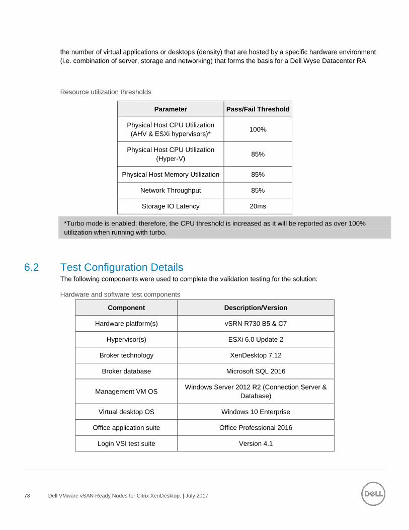
78 Dell VMware vSAN Ready Nodes for Citrix XenDesktop. | July 2017
the number of virtual applications or desktops (density) that are hosted by a specific hardware environment
(i.e. combination of server, storage and networking) that forms the basis for a Dell Wyse Datacenter RA
Resource utilization thresholds
Parameter Pass/Fail Threshold
Physical Host CPU Utilization
(AHV & ESXi hypervisors)* 100%
Physical Host CPU Utilization
(Hyper-V) 85%
Physical Host Memory Utilization 85%
Network Throughput 85%
Storage IO Latency 20ms
*Turbo mode is enabled; therefore, the CPU threshold is increased as it will be reported as over 100%
utilization when running with turbo.
6.2 Test Configuration Details The following components were used to complete the validation testing for the solution:
Hardware and software test components
Component Description/Version
Hardware platform(s) vSRN R730 B5 & C7
Hypervisor(s) ESXi 6.0 Update 2
Broker technology XenDesktop 7.12
Broker database Microsoft SQL 2016
Management VM OS Windows Server 2012 R2 (Connection Server &
Database)
Virtual desktop OS Windows 10 Enterprise
Office application suite Office Professional 2016
Login VSI test suite Version 4.1
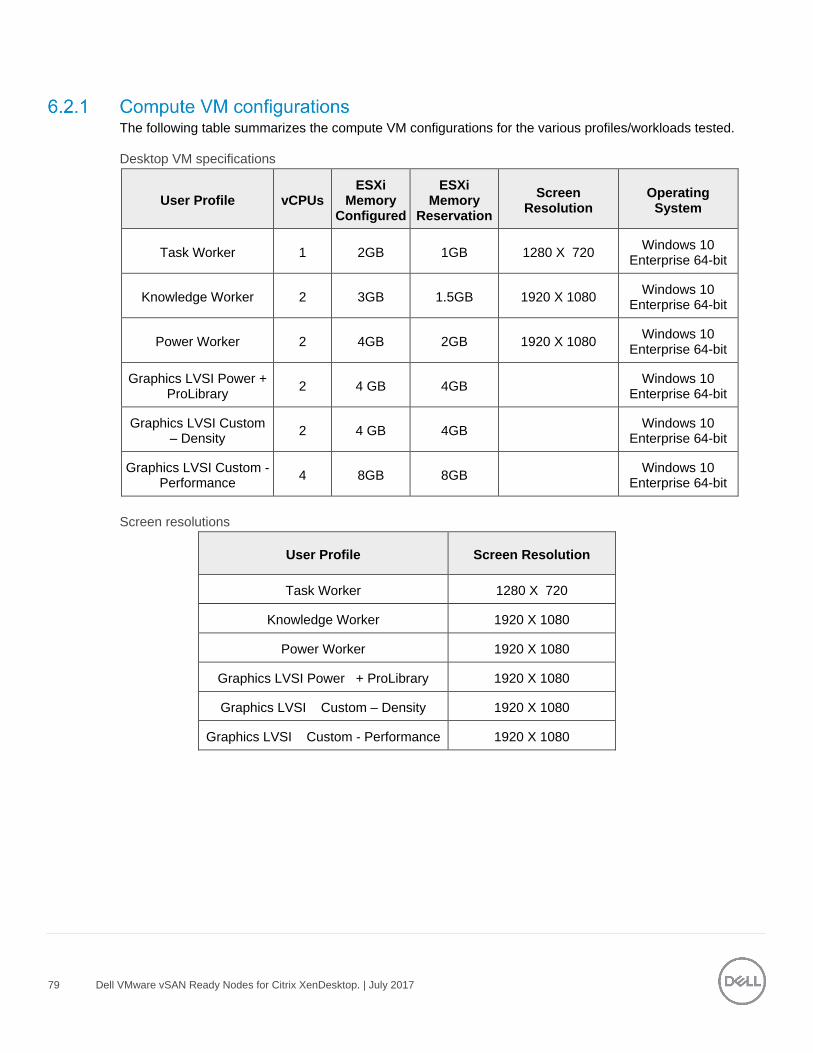
79 Dell VMware vSAN Ready Nodes for Citrix XenDesktop. | July 2017
The following table summarizes the compute VM configurations for the various profiles/workloads tested.
Desktop VM specifications
User Profile vCPUs ESXi
Memory Configured
ESXi Memory
Reservation
Screen Resolution
Operating System
Task Worker 1 2GB 1GB 1280 X 720 Windows 10
Enterprise 64-bit
Knowledge Worker 2 3GB 1.5GB 1920 X 1080 Windows 10
Enterprise 64-bit
Power Worker 2 4GB 2GB 1920 X 1080 Windows 10
Enterprise 64-bit
Graphics LVSI Power + ProLibrary
2 4 GB 4GB Windows 10
Enterprise 64-bit
Graphics LVSI Custom – Density
2 4 GB 4GB Windows 10
Enterprise 64-bit
Graphics LVSI Custom - Performance
4 8GB 8GB Windows 10
Enterprise 64-bit
Screen resolutions
User Profile Screen Resolution
Task Worker 1280 X 720
Knowledge Worker 1920 X 1080
Power Worker 1920 X 1080
Graphics LVSI Power + ProLibrary 1920 X 1080
Graphics LVSI Custom – Density 1920 X 1080
Graphics LVSI Custom - Performance 1920 X 1080
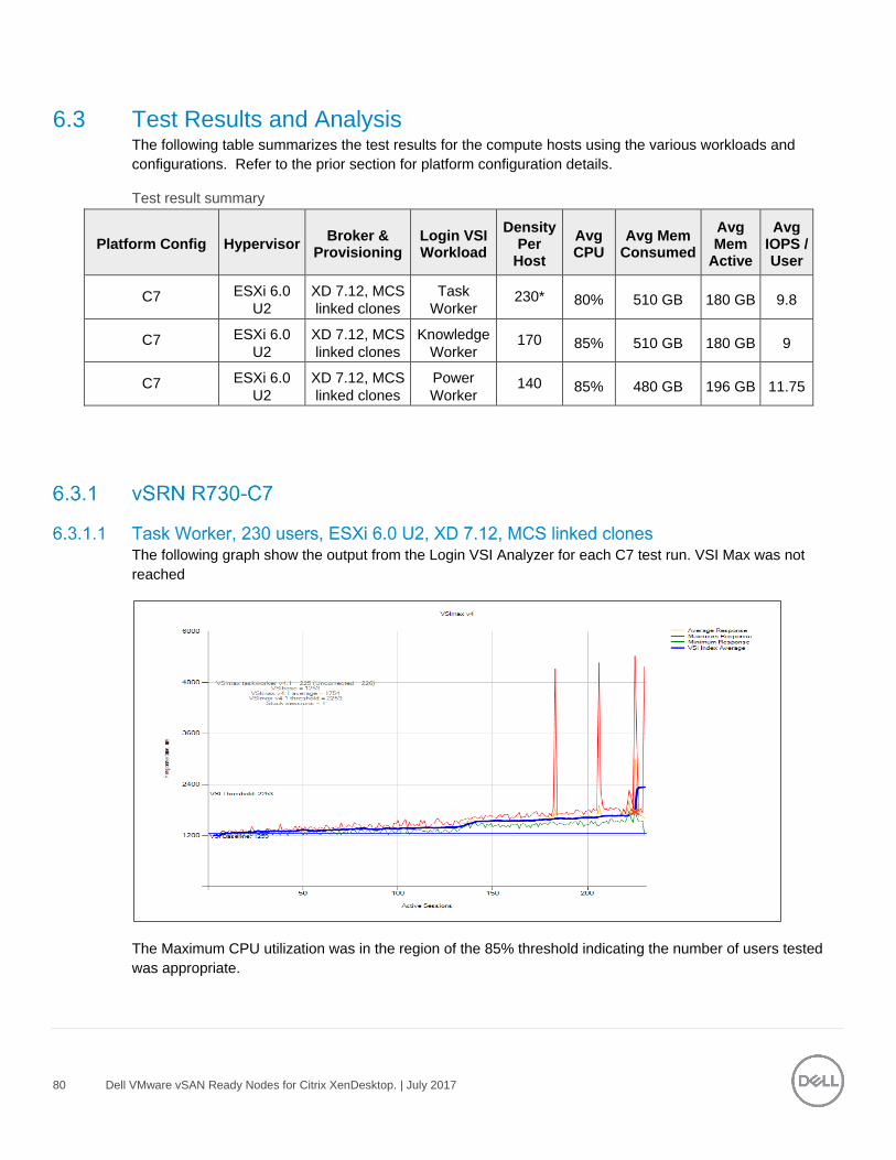
80 Dell VMware vSAN Ready Nodes for Citrix XenDesktop. | July 2017
6.3 Test Results and Analysis The following table summarizes the test results for the compute hosts using the various workloads and
configurations. Refer to the prior section for platform configuration details.
Test result summary
Platform Config Hypervisor Broker &
Provisioning Login VSI Workload
Density Per
Host
Avg CPU
Avg Mem Consumed
Avg Mem
Active
Avg IOPS / User
C7 ESXi 6.0
U2
XD 7.12, MCS
linked clones
Task
Worker 230* 80% 510 GB 180 GB 9.8
C7 ESXi 6.0
U2
XD 7.12, MCS
linked clones
Knowledge
Worker 170 85% 510 GB 180 GB 9
C7 ESXi 6.0
U2
XD 7.12, MCS
linked clones
Power
Worker 140 85% 480 GB 196 GB 11.75
The following graph show the output from the Login VSI Analyzer for each C7 test run. VSI Max was not
reached
The Maximum CPU utilization was in the region of the 85% threshold indicating the number of users tested
was appropriate.

81 Dell VMware vSAN Ready Nodes for Citrix XenDesktop. | July 2017
Latency on the datastore spiked temporarily during the boot phase of the test but quickly settled once all the VMs were booted. For the logon and steady state phase of each test, the latency remained well below the 20ms threshold reaching a max of 2-3 ms during the test run.
The IOPS peaked during the boot phase and for each profile test and then settled thereafter during the login phase and reduced once steady state was reached.
This chart was captured from within vSphere and was a feature released with vSAN6.2 so we do not need to use vSAN Observer as was previously the case with past vSAN validations.
The statistics below are on a per host basis so as vSAN scales linearly; to calculate the total IOPs for a three
node cluster you would multiple by three
Memory usage is monitored on the ESXi host, memory usage metrics monitored are consumed, active,
balloon and swap used, as swap and ballooning usage would indicate host memory reached saturation point
and the VM performance may start to deteriorating. All tests were carried out on hosts with 512 GB of
physical memory installed.
Reboot Logon Steady State Logoff
0
10
20
30
40
50
60
70
80
90
100
15
:05
15
:10
15
:15
15
:20
15
:25
15
:30
15
:35
15
:40
15
:45
15
:50
15
:55
16
:00
16
:05
16
:10
16
:15
16
:20
16
:25
16
:30
16
:35
16
:40
16
:45
16
:50
16
:55
Task Worker 230 - CPU Usage %
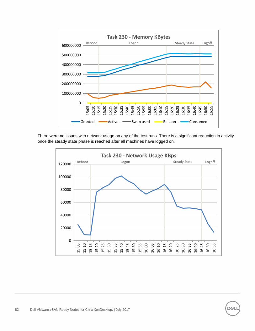
82 Dell VMware vSAN Ready Nodes for Citrix XenDesktop. | July 2017
There were no issues with network usage on any of the test runs. There is a significant reduction in activity
once the steady state phase is reached after all machines have logged on.
Reboot Logon Steady State Logoff
0
100000000
200000000
300000000
400000000
500000000
600000000
15
:05
15
:10
15
:15
15
:20
15
:25
15
:30
15
:35
15
:40
15
:45
15
:50
15
:55
16
:00
16
:05
16
:10
16
:15
16
:20
16
:25
16
:30
16
:35
16
:40
16
:45
16
:50
16
:55
Task 230 - Memory KBytes
Granted Active Swap used Balloon Consumed
Reboot Logon Steady State Logoff
0
20000
40000
60000
80000
100000
120000
15
:05
15
:10
15
:15
15
:20
15
:25
15
:30
15
:35
15
:40
15
:45
15
:50
15
:55
16
:00
16
:05
16
:10
16
:15
16
:20
16
:25
16
:30
16
:35
16
:40
16
:45
16
:50
16
:55
Task 230 - Network Usage KBps
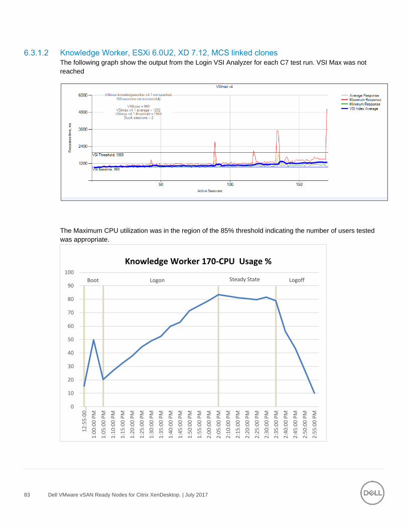
83 Dell VMware vSAN Ready Nodes for Citrix XenDesktop. | July 2017
The following graph show the output from the Login VSI Analyzer for each C7 test run. VSI Max was not
reached
The Maximum CPU utilization was in the region of the 85% threshold indicating the number of users tested
was appropriate.
Boot Logon Steady State Logoff
0
10
20
30
40
50
60
70
80
90
100
12:55:00…
1:0
0:0
0 P
M
1:0
5:0
0 P
M
1:1
0:0
0 P
M
1:1
5:0
0 P
M
1:2
0:0
0 P
M
1:2
5:0
0 P
M
1:3
0:0
0 P
M
1:3
5:0
0 P
M
1:4
0:0
0 P
M
1:4
5:0
0 P
M
1:5
0:0
0 P
M
1:5
5:0
0 P
M
2:0
0:0
0 P
M
2:0
5:0
0 P
M
2:1
0:0
0 P
M
2:1
5:0
0 P
M
2:2
0:0
0 P
M
2:2
5:0
0 P
M
2:3
0:0
0 P
M
2:3
5:0
0 P
M
2:4
0:0
0 P
M
2:4
5:0
0 P
M
2:5
0:0
0 P
M
2:5
5:0
0 P
M
Knowledge Worker 170-CPU Usage %
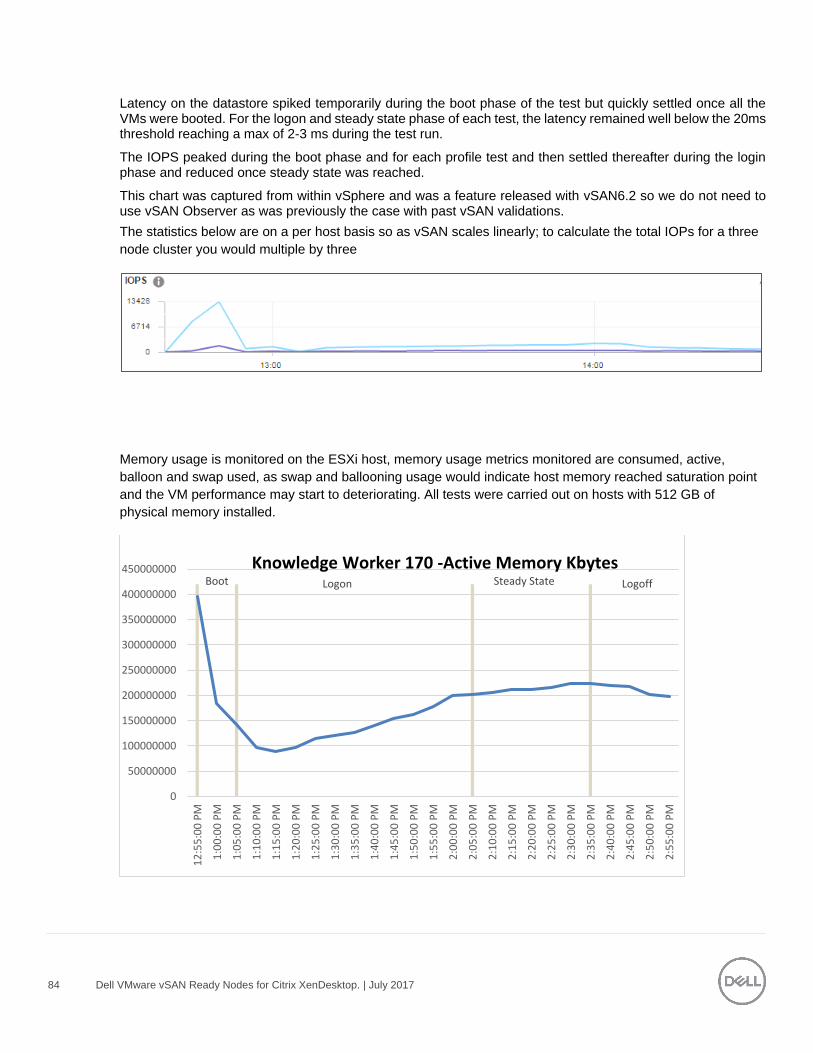
84 Dell VMware vSAN Ready Nodes for Citrix XenDesktop. | July 2017
Latency on the datastore spiked temporarily during the boot phase of the test but quickly settled once all the VMs were booted. For the logon and steady state phase of each test, the latency remained well below the 20ms threshold reaching a max of 2-3 ms during the test run.
The IOPS peaked during the boot phase and for each profile test and then settled thereafter during the login phase and reduced once steady state was reached.
This chart was captured from within vSphere and was a feature released with vSAN6.2 so we do not need to use vSAN Observer as was previously the case with past vSAN validations.
The statistics below are on a per host basis so as vSAN scales linearly; to calculate the total IOPs for a three
node cluster you would multiple by three
Memory usage is monitored on the ESXi host, memory usage metrics monitored are consumed, active,
balloon and swap used, as swap and ballooning usage would indicate host memory reached saturation point
and the VM performance may start to deteriorating. All tests were carried out on hosts with 512 GB of
physical memory installed.
Boot Logon Steady State Logoff
0
50000000
100000000
150000000
200000000
250000000
300000000
350000000
400000000
450000000
12
:55
:00
PM
1:0
0:0
0 P
M
1:0
5:0
0 P
M
1:1
0:0
0 P
M
1:1
5:0
0 P
M
1:2
0:0
0 P
M
1:2
5:0
0 P
M
1:3
0:0
0 P
M
1:3
5:0
0 P
M
1:4
0:0
0 P
M
1:4
5:0
0 P
M
1:5
0:0
0 P
M
1:5
5:0
0 P
M
2:0
0:0
0 P
M
2:0
5:0
0 P
M
2:1
0:0
0 P
M
2:1
5:0
0 P
M
2:2
0:0
0 P
M
2:2
5:0
0 P
M
2:3
0:0
0 P
M
2:3
5:0
0 P
M
2:4
0:0
0 P
M
2:4
5:0
0 P
M
2:5
0:0
0 P
M
2:5
5:0
0 P
M
Knowledge Worker 170 -Active Memory Kbytes

85 Dell VMware vSAN Ready Nodes for Citrix XenDesktop. | July 2017
There were no issues with network usage on any of the test runs. There is a significant reduction in activity
once the steady state phase is reached after all machines have logged on.
Boot Logon Steady State Logoff
0
100000000
200000000
300000000
400000000
500000000
600000000
12
:55
:00
PM
1:0
0:0
0 P
M
1:0
5:0
0 P
M
1:1
0:0
0 P
M
1:1
5:0
0 P
M
1:2
0:0
0 P
M
1:2
5:0
0 P
M
1:3
0:0
0 P
M
1:3
5:0
0 P
M
1:4
0:0
0 P
M
1:4
5:0
0 P
M
1:5
0:0
0 P
M
1:5
5:0
0 P
M
2:0
0:0
0 P
M
2:0
5:0
0 P
M
2:1
0:0
0 P
M
2:1
5:0
0 P
M
2:2
0:0
0 P
M
2:2
5:0
0 P
M
2:3
0:0
0 P
M
2:3
5:0
0 P
M
2:4
0:0
0 P
M
2:4
5:0
0 P
M
2:5
0:0
0 P
M
2:5
5:0
0 P
M
Knowledge Worker 170-Consumed Memory Kbytes
Boot Logon Steady State Logoff
0
50000
100000
150000
200000
250000
12
:55
:00
PM
1:0
0:0
0 P
M
1:0
5:0
0 P
M
1:1
0:0
0 P
M
1:1
5:0
0 P
M
1:2
0:0
0 P
M
1:2
5:0
0 P
M
1:3
0:0
0 P
M
1:3
5:0
0 P
M
1:4
0:0
0 P
M
1:4
5:0
0 P
M
1:5
0:0
0 P
M
1:5
5:0
0 P
M
2:0
0:0
0 P
M
2:0
5:0
0 P
M
2:1
0:0
0 P
M
2:1
5:0
0 P
M
2:2
0:0
0 P
M
2:2
5:0
0 P
M
2:3
0:0
0 P
M
2:3
5:0
0 P
M
2:4
0:0
0 P
M
2:4
5:0
0 P
M
2:5
0:0
0 P
M
2:5
5:0
0 P
M
Knowledge Worker 170 -Network Usage KBps
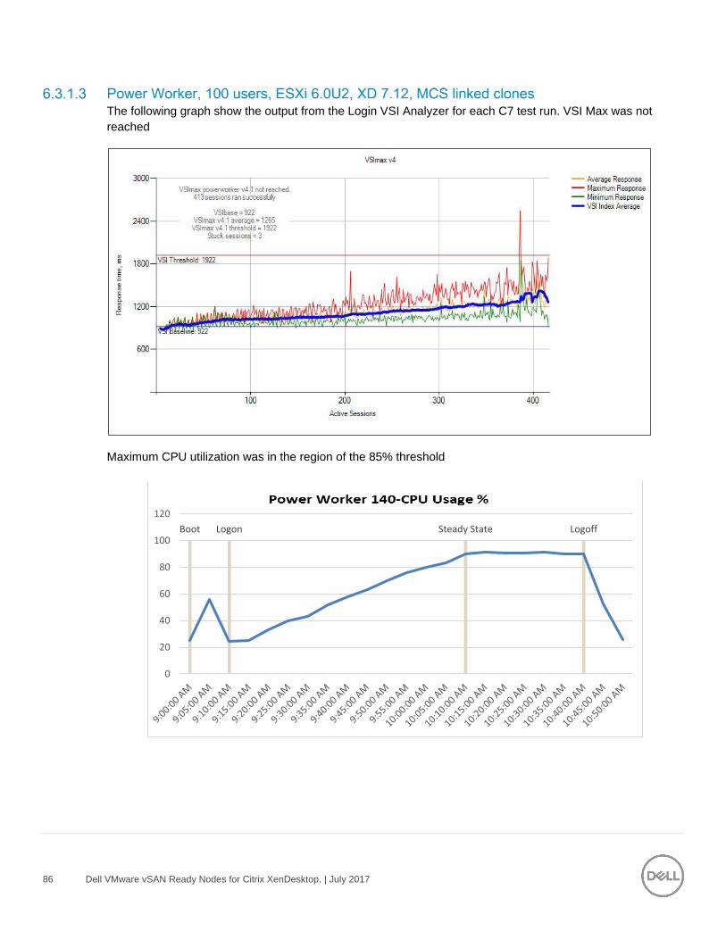
86 Dell VMware vSAN Ready Nodes for Citrix XenDesktop. | July 2017
The following graph show the output from the Login VSI Analyzer for each C7 test run. VSI Max was not
reached
Maximum CPU utilization was in the region of the 85% threshold
Boot Logon Steady State Logoff
0
20
40
60
80
100
120
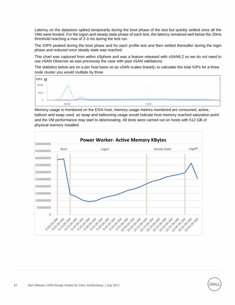
87 Dell VMware vSAN Ready Nodes for Citrix XenDesktop. | July 2017
Latency on the datastore spiked temporarily during the boot phase of the test but quickly settled once all the VMs were booted. For the logon and steady state phase of each test, the latency remained well below the 20ms threshold reaching a max of 2-3 ms during the test run.
The IOPS peaked during the boot phase and for each profile test and then settled thereafter during the login phase and reduced once steady state was reached.
This chart was captured from within vSphere and was a feature released with vSAN6.2 so we do not need to use vSAN Observer as was previously the case with past vSAN validations.
The statistics below are on a per host basis so as vSAN scales linearly; to calculate the total IOPs for a three
node cluster you would multiple by three
Memory usage is monitored on the ESXi host, memory usage metrics monitored are consumed, active,
balloon and swap used, as swap and ballooning usage would indicate host memory reached saturation point
and the VM performance may start to deteriorating. All tests were carried out on hosts with 512 GB of
physical memory installed.
Boot Logon Steady State Logoff
0
50000000
100000000
150000000
200000000
250000000
300000000
350000000
400000000
450000000
500000000Power Worker- Active Memory KBytes
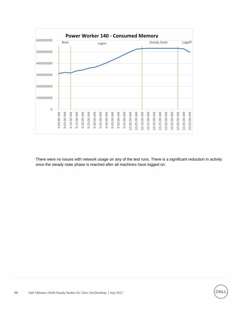
88 Dell VMware vSAN Ready Nodes for Citrix XenDesktop. | July 2017
There were no issues with network usage on any of the test runs. There is a significant reduction in activity
once the steady state phase is reached after all machines have logged on.
Boot Logon Steady State Logoff
0
100000000
200000000
300000000
400000000
500000000
600000000
9:0
0:0
0 A
M
9:0
5:0
0 A
M
9:1
0:0
0 A
M
9:1
5:0
0 A
M
9:2
0:0
0 A
M
9:2
5:0
0 A
M
9:3
0:0
0 A
M
9:3
5:0
0 A
M
9:4
0:0
0 A
M
9:4
5:0
0 A
M
9:5
0:0
0 A
M
9:5
5:0
0 A
M
10
:00
:00
AM
10
:05
:00
AM
10
:10
:00
AM
10
:15
:00
AM
10
:20
:00
AM
10
:25
:00
AM
10
:30
:00
AM
10
:35
:00
AM
10
:40
:00
AM
10
:45
:00
AM
10
:50
:00
AM
Power Worker 140 - Consumed Memory
89 Dell VMware vSAN Ready Nodes for Citrix XenDesktop. | July 2017
Boot Logon Steady State Logoff
0
50000
100000
150000
200000
250000
9:0
0:0
0 A
M
9:0
5:0
0 A
M
9:1
0:0
0 A
M
9:1
5:0
0 A
M
9:2
0:0
0 A
M
9:2
5:0
0 A
M
9:3
0:0
0 A
M
9:3
5:0
0 A
M
9:4
0:0
0 A
M
9:4
5:0
0 A
M
9:5
0:0
0 A
M
9:5
5:0
0 A
M
10
:00
:00
AM
10
:05
:00
AM
10
:10
:00
AM
10
:15
:00
AM
10
:20
:00
AM
10
:25
:00
AM
10
:30
:00
AM
10
:35
:00
AM
10
:40
:00
AM
10
:45
:00
AM
10
:50
:00
AM
Power Worker 140-Network Usage
90 Dell VMware vSAN Ready Nodes for Citrix XenDesktop. | July 2017
Acknowledgements
Thanks to David Hulama of the Wyse Technical Marketing team for his support and assistance with VMware
data center EUC programs at Dell. David is a Senior Technical Marketing Advisor for VMware VDI solutions
at Dell. David has a broad technical background in a variety of technical areas and expertise in enterprise-
class virtualization solutions.
Thanks to Mike Hayes from the Limerick CSC team for his help and support with the Graphics Functionality
Testing that was completed on vSRN. Mike is a Solutions Architect working at the Dell Customer Solution
Center in Limerick, Ireland. Responsible for Client Solutions and VDI engagements at the Center in EMEA,
Mike has a strong background in Desktop and Server Virtualization with over 15 years’ experience working in
Enterprise class IT environments. Highly skilled in Microsoft, VMware and Citrix platforms, Mike primarily
works on design workshop and Proof-Of-Concept activity around VDI and high performance graphics,
including Workstation and VR Technology. Twitter:@MikeJAtDell
Thanks to Kevin Corey from the Limerick CSC team for his help and support with the network setup for this
validation. Kevin is a Network Solution Architect with over 17 years’ experience in working with enterprise
environments. Primarily focusing on data center networking, Kevin has experience working with technology
from all major network vendors.
Thanks to Rick Biedler for his support during this program, Rick is the Engineering Director for Datacenter
Appliances at Dell, managing the development and delivery of enterprise class desktop virtualization solutions
based on Dell Datacenter components and core virtualization platforms.
91 Dell VMware vSAN Ready Nodes for Citrix XenDesktop. | July 2017
About the Authors
Keith Keogh is the Lead Architect for VMware solutions in the Cloud Client Engineering Team at Dell. Keith
has extensive experience with the Design, Implementation and Validation of EUC Enterprise Solutions.
Peter Fine is the Chief Architect and CTO of EUC Enterprise Engineering at Dell. Peter owns the strategy,
architecture and leads the engineering of the datacenter EUC product and solutions portfolio. Peter also has
extensive experience building and managing data centers for Fortune500 and financial services companies.
Follow Peter @ExitTheFastLane or www.ExitTheFastLane.com.
Jerry Van Blaricom is a Lead Architect in the Cloud Client Solutions Engineering Group at Dell. Jerry has
extensive experience with the design and implementation of a broad range of enterprise systems and is
focused on making Dell’s virtualization offerings consistently best in class.