Embed Size (px)
Citation preview
Dell™ Digital Forensics
Solution Guide
Notes, Cautions, and Warnings
NOTE: A NOTE indicates important information that helps you make better use of
your computer.
CAUTION: A CAUTION indicates potential damage to hardware or loss of data if
instructions are not followed.
WARNING: A WARNING indicates a potential for property damage, personal
injury, or death.
____________________
Information in this document is subject to change without notice.© 2011 Dell Inc. All rights reserved.
Reproduction of these materials in any manner whatsoever without the written permission of Dell Inc. is strictly forbidden.
Trademarks used in this text: Dell™ , the DELL™ logo, PowerEdge™, EqualLogic™, and PowerConnect™ are trademarks of Dell Inc. Oracle® is a registered trademark of Oracle Corporation and/or its affiliates. Citrix®is a registered trademark of Citrix Systems, Inc. in the United States and/or other countries.
Other trademarks and trade names may be used in this document to refer to either the entities claiming the marks and names or their products. Dell Inc. disclaims any proprietary interest in trademarks and trade names other than its own.
2011 - 07 Rev. A00
Contents 1
Contents
1 Introduction . . . . . . . . . . . . . . . . . . . . . . . . 7
The Dell Digital Forensics Lifecycle . . . . . . . . . . . 9
Dell’s Solution Eases Industry Pain Points . . . . . . . 11
Solution Components . . . . . . . . . . . . . . . . . . 12
In the Field . . . . . . . . . . . . . . . . . . . . . 12
In the Datacenter . . . . . . . . . . . . . . . . . . 13
About This Document . . . . . . . . . . . . . . . . . . 16
Related Documentation and Resources . . . . . . . . . 16
2 Triage . . . . . . . . . . . . . . . . . . . . . . . . . . . . 17
What is Triage? . . . . . . . . . . . . . . . . . . . . . 17
Dell’s Triage Solution Advantage . . . . . . . . . . . . 17
Collecting Digital Forensics Evidence . . . . . . . . . 19
Standard vs. Live Acquisition . . . . . . . . . . . . . . 20
How to Perform Triage Using the Dell Digital
Forensics Solution . . . . . . . . . . . . . . . . . . . . 20
Turn on Your Dell Ruggedized Laptop . . . . . . . 20
Burn a Boot CD for Standard Acquisition
Procedures . . . . . . . . . . . . . . . . . . . . . 21
Register a Collector or Store Disk . . . . . . . . . 21
Clean a Collector or Store Disk . . . . . . . . . . . 23
2 Contents
Configure a Collector Profile . . . . . . . . . . . . 23
Deploy Triage Tools . . . . . . . . . . . . . . . . . 33
Reviewing Collected Files After Triage . . . . . . . 36
3 Ingest . . . . . . . . . . . . . . . . . . . . . . . . . . . 39
Datacenter-enabled EnCase 6 . . . . . . . . . . . . . . 39
Single-server Solution . . . . . . . . . . . . . . . 40
Multi-server Solution (High Availability) . . . . . . 40
Datacenter-enabled FTK 1.8 . . . . . . . . . . . . . . . 42
Single FTK 1.8 Session Per Desktop . . . . . . . . 42
Multiple FTK 1.8 Sessions Per Desktop . . . . . . . 42
Datacenter-enabled FTK 3 . . . . . . . . . . . . . . . . 43
Single FTK 3 Server Solution . . . . . . . . . . . . 44
Multiserver Solution (No High Availability) . . . . . 44
FTK 3 Lab Edition . . . . . . . . . . . . . . . . . . . . . 46
Multiple Forensics Applications Delivered to
One Desktop . . . . . . . . . . . . . . . . . . . . . . . 47
Network Configuration Recommendations . . . . . . . 48
How to Perform Ingest Using the Dell Digital
Forensics Solution . . . . . . . . . . . . . . . . . . . . 51
Ingest Using SPEKTOR . . . . . . . . . . . . . . . 51
Ingest Using EnCase . . . . . . . . . . . . . . . . 53
Ingest Using FTK 1.8 and 3.0 Datacenter-enabled . 56
Ingest Using FTK 3 Lab Edition . . . . . . . . . . . 59
4 Store . . . . . . . . . . . . . . . . . . . . . . . . . . . 63
Efficiency . . . . . . . . . . . . . . . . . . . . . . . . . 63
Contents 3
Scalability . . . . . . . . . . . . . . . . . . . . . . . . 64
Security . . . . . . . . . . . . . . . . . . . . . . . . . 64
Physical Access Layer . . . . . . . . . . . . . . . 64
Administrative Control Layer and Active Directory 65
Computer-Based Security Layer and
Active Directory . . . . . . . . . . . . . . . . . . 65
Tiered Storage . . . . . . . . . . . . . . . . . . . . . . 66
Matching Evidence Archiving and Retrieval to the
Life of the Case. . . . . . . . . . . . . . . . . . . . . . 67
How to Set Up Storage Security Using the Dell
Digital Forensics Solution and Active Directory . . . . 68
Creating and Populating Groups in Active Directory 68
Applying Security Policies Using Group
Policy Objects . . . . . . . . . . . . . . . . . . . 69
Creating and Editing GPOs . . . . . . . . . . . . . 69
Editing a New GPO (Windows Server 2008) . . . . 70
Active Directory Support for Secure Password
Policies . . . . . . . . . . . . . . . . . . . . . . . 70
Active Directory User Accounts . . . . . . . . . . 71
Create a Non-administrative User Account . . . . 73
Setting Up Security for Individual Case and
Evidence Files . . . . . . . . . . . . . . . . . . . 74
5 Analyze . . . . . . . . . . . . . . . . . . . . . . . . . . 77
Types of Analysis. . . . . . . . . . . . . . . . . . . . . 77
Hash Analysis . . . . . . . . . . . . . . . . . . . . 77
File Signature Analysis . . . . . . . . . . . . . . . 78
What is Distributed Processing? . . . . . . . . . . . . 78
Using Distributed Processing in FTK 3.1 . . . . . . . . 79
4 Contents
Checking the Installation . . . . . . . . . . . . . . 81
Finding Files on the Network . . . . . . . . . . . . . . 81
Analysis Using FTK . . . . . . . . . . . . . . . . . . . . 82
Open an Existing Case . . . . . . . . . . . . . . . 82
Processing Case Evidence . . . . . . . . . . . . . 82
Analysis Using EnCase . . . . . . . . . . . . . . . . . . 82
Open an Existing Case . . . . . . . . . . . . . . . 82
Create an Analysis Job . . . . . . . . . . . . . . . 83
Run an Analysis Job . . . . . . . . . . . . . . . . 83
Performing a Signature Analysis . . . . . . . . . . 84
Viewing Signature Analysis Results . . . . . . . . 84
6 Present . . . . . . . . . . . . . . . . . . . . . . . . . . 85
How to Create Reports Using the Dell Digital
Forensics Solution . . . . . . . . . . . . . . . . . . . . 85
Create and Export Reports Using EnCase 6 . . . . 85
Reports Using FTK. . . . . . . . . . . . . . . . . . 86
7 Archive . . . . . . . . . . . . . . . . . . . . . . . . . . 87
Client One-Click Archive Solution. . . . . . . . . . . . 88
Dell Backup Recommendations . . . . . . . . . . . . . 89
Backup of Evidence and Case files . . . . . . . . . 89
Off-host vs. Network . . . . . . . . . . . . . . . . 90
How to Archive Using the Dell Digital Forensics
Solution. . . . . . . . . . . . . . . . . . . . . . . . . . 93
On-Demand Archiving . . . . . . . . . . . . . . . 93
Requirements . . . . . . . . . . . . . . . . . . . . 93
Installation . . . . . . . . . . . . . . . . . . . . . 93
Contents 5
Archiving Using NTP Software ODDM . . . . . . . 93
8 Troubleshooting . . . . . . . . . . . . . . . . . . . . 95
General Troubleshooting Tips . . . . . . . . . . . . . . 95
Forensics Software-Specific Issues . . . . . . . . . . 95
EnCase: EnCase launches in Acquisition Mode . . 95
FTK Lab: Browser launched by client cannot
display User Interface . . . . . . . . . . . . . . . 96
FTK 1.8: 5000 object limit\trial version message . . 96
FTK 1.8: Cannot Access Temp File error appears
on launch . . . . . . . . . . . . . . . . . . . . . . 96
Citrix Issues . . . . . . . . . . . . . . . . . . . . . . . 96
Citrix: Applications won’t launch . . . . . . . . . . 96
Frozen or Crashed Citrix Sessions . . . . . . . . . 97
Index . . . . . . . . . . . . . . . . . . . . . . . . . . . . . . . 99

6 Contents
Introduction 7
Introduction
In recent years there has been an exponential increase in the volume, velocity, variety, and sophistication of digital activity by criminals and terrorist groups around the world. Today, most crimes have a digital component. Some have called it a digital tsunami. This growth has been augmented by dramatic advances in electronic hardware. The expanding diversity of consumer electronic devices and their increasing memory and storage capacity offer criminals and terrorists a wealth of opportunity to hide harmful information.
It is not uncommon for PCs and laptops to come with hard drives that measure in the hundreds of Gigabytes of storage. The latest hard drives include options for one or four Terabytes. Consider that a single Terabyte can store the content of two hundred DVDs: a vast amount of storage representing a problem that will only continue to grow.
From PCs to laptops, mobile phones to thumb drives and even game consoles, digital forensics professionals are being pushed to the limit to clone, ingest, index, analyze, and store growing amounts of suspect data while preserving the digital chain of custody and continuing to protect citizens.
StoreIngest Store Analyze ArchiveTriage Present
8 Introduction
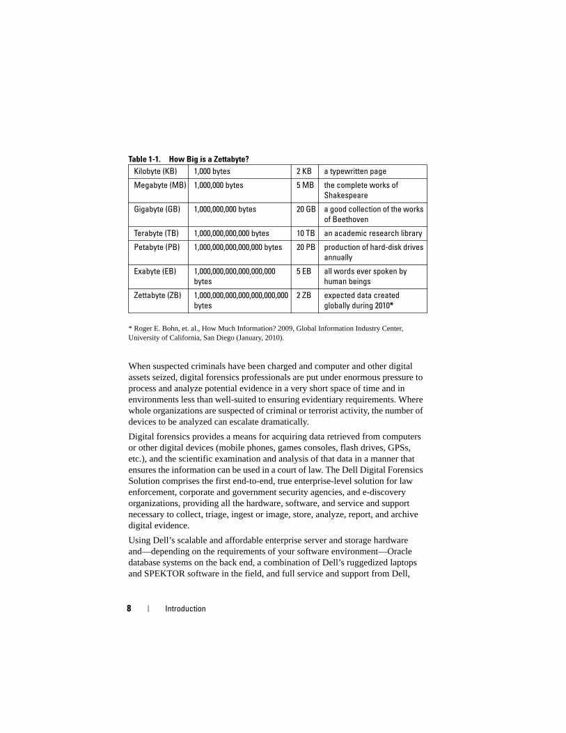
Table 1-1. How Big is a Zettabyte?
* Roger E. Bohn, et. al., How Much Information? 2009, Global Information Industry Center, University of California, San Diego (January, 2010).
When suspected criminals have been charged and computer and other digital assets seized, digital forensics professionals are put under enormous pressure to process and analyze potential evidence in a very short space of time and in environments less than well-suited to ensuring evidentiary requirements. Where whole organizations are suspected of criminal or terrorist activity, the number of devices to be analyzed can escalate dramatically.
Digital forensics provides a means for acquiring data retrieved from computers or other digital devices (mobile phones, games consoles, flash drives, GPSs, etc.), and the scientific examination and analysis of that data in a manner that ensures the information can be used in a court of law. The Dell Digital Forensics Solution comprises the first end-to-end, true enterprise-level solution for law enforcement, corporate and government security agencies, and e-discovery organizations, providing all the hardware, software, and service and support necessary to collect, triage, ingest or image, store, analyze, report, and archive digital evidence.
Using Dell’s scalable and affordable enterprise server and storage hardware and—depending on the requirements of your software environment—Oracle database systems on the back end, a combination of Dell’s ruggedized laptops and SPEKTOR software in the field, and full service and support from Dell,
Kilobyte (KB) 1,000 bytes 2 KB a typewritten page
Megabyte (MB) 1,000,000 bytes 5 MB the complete works of
Shakespeare
Gigabyte (GB) 1,000,000,000 bytes 20 GB a good collection of the works
of Beethoven
Terabyte (TB) 1,000,000,000,000 bytes 10 TB an academic research library
Petabyte (PB) 1,000,000,000,000,000 bytes 20 PB production of hard-disk drives
annually
Exabyte (EB) 1,000,000,000,000,000,000
bytes
5 EB all words ever spoken by
human beings
Zettabyte (ZB) 1,000,000,000,000,000,000,000
bytes
2 ZB expected data created
globally during 2010*
Introduction 9
investigative personnel can conduct digital forensics data triage and collection quickly and simply, ensuring chain-of-custody from the field to the datacenter, and into the courtroom.
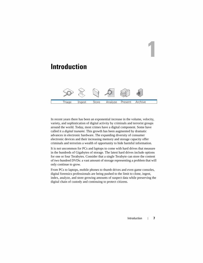
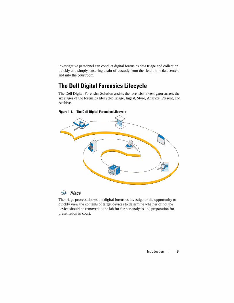
The Dell Digital Forensics LifecycleThe Dell Digital Forensics Solution assists the forensics investigator across the six stages of the forensics lifecycle: Triage, Ingest, Store, Analyze, Present, and Archive.
Figure 1-1. The Dell Digital Forensics Lifecycle
Triage
The triage process allows the digital forensics investigator the opportunity to quickly view the contents of target devices to determine whether or not the device should be removed to the lab for further analysis and preparation for presentation in court.
10 Introduction
Ingest
Ingest is the stage of the digital forensics process in which the target data is imaged (unless it has been imaged in the field as part of the Triage stage), and an exact copy of the suspect storage device is created in such a way that the integrity of the duplicate can be assured by comparing hashes of both the original and duplicate data drives.
In common with existing practices, suspect data is imaged in the Dell Digital Forensics Solution. Instead of imaging data onto a single workstation, however, the imaged data is ingested into a central evidence repository. By ingesting data immediately into the datacenter, data is available to multiple analysts, transfer from one device to another is minimized, and productivity and efficiency is dramatically improved. Ingestion can, however, take place in the field if the target storage capacity is small enough. The Dell Digital Forensics Solution provides onsite ingestion through the use of an optional SPEKTOR Imager module.
Store
The Dell Digital Forensics Solution provides a wide range of possible storage and network access options to suit the individual customer. High-speed storage and retrieval across an enterprise-level network environment allow for a multiuser configuration that increases efficiency and productivity. Analysts will no longer have to allocate their individual computing assets to complete evidence analysis, as all this will happen on the server dedicated for that purpose.
Analyze
The parallel processing capability provided by the Dell Digital Forensics Solution allows the analyst to index and triage data on high-performance servers rather than on far less powerful individual PCs. Additionally, multiple analyst sessions may be run concurrently on single or multiple workstations using the back-end configurations that comprise the Solution. This capability helps protect both system and evidence integrity, helps prevent the need for workstation rebuilds if malicious code is mistakenly executed, helps preserve chain of custody, and obviates the need for analyst workstation rebuilds when moving from one case to the next. In the Digital Forensics environment, Chain
Introduction 11
of Custody may be defined as maintaining the integrity of digital data as evidence from the time it is collected, through the time findings are reported, and until the time it may be presented in a court of law.
Present
Using the Dell Digital Forensics Solution, viewing teams and investigators can access potential case evidence securely and in real time, thus mitigating the need to release evidence on DVDs or to require experts to travel to the lab for file access purposes.
Archive
The Dell Solution offers formalized backup, recovery, and archiving infrastructure to help optimize cooperation between agencies and security divisions and even across borders, free up administrative overhead, provide consistency between labs, and minimize risks to the digital chain of custody.
Additionally, Dell’s Digital Forensics Solution blueprint includes an optional search component that allows for information correlation between ingested data sets.
Dell’s Solution Eases Industry Pain PointsUsing the Dell Digital Forensics Solution can make the process of bringing digital evidence from the crime scene to the courtroom infinitely simpler for investigative professionals by providing:
• State-of-the-art datacenter networking that speeds ingestion, analysis, and sharing of digital information
• Information assurance by further automating the digital forensics process, thereby lowering the risk of error and data compromise
• Additional data integrity assurance, currently through the use of the most secure hash protocols, and soon through the implementation of an auditing feature that will help automate chain-of-custody records
NOTE: Any conclusions or recommendations in this document that may resemble
legal advice should be vetted through legal counsel. Always check with your local
jurisdiction, local prosecutors, and local forensics laboratory regarding their
preferred method(s) of digital evidence collection.
12 Introduction
• An end-to-end solution that significantly lowers the complexity of planning, implementing and managing an enterprise-level digital forensics process
• An affordable and flexible solution that is modular and scalable, expandable and pay-as-you-go
Solution Components
In the Field
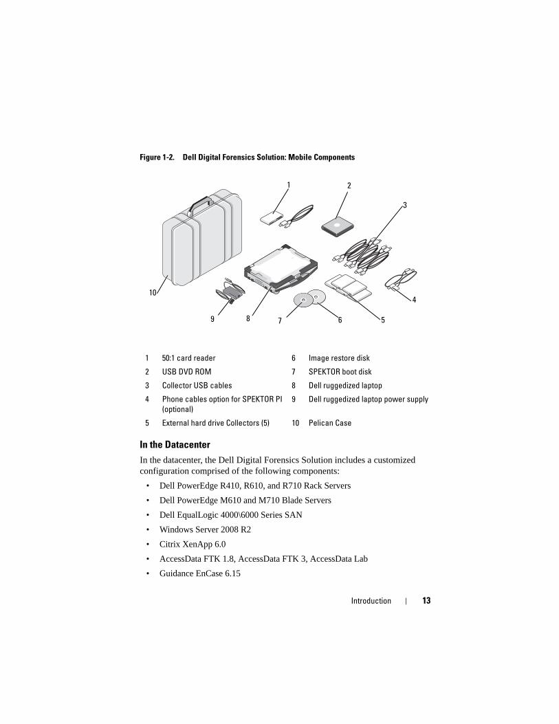
The mobile portion of the solution fits into one hardshell case designed to fit into the overhead bin of an aircraft. The rugged case carries all the tools and software required for onsite triage of suspect storage devices, and it includes a Dell E6400 XFR Ruggedized Laptop with SPEKTOR forensics software pre-installed, Tableau Forensics Write-Blockers with accessories, an optional number of external USB hard drives that are licensed to work with the SPEKTOR software as triage image collectors, a 50:1 card reader, and the adaptors and cables listed in Figure 1-2.
Introduction 13
Figure 1-2. Dell Digital Forensics Solution: Mobile Components
In the Datacenter
In the datacenter, the Dell Digital Forensics Solution includes a customized configuration comprised of the following components:
• Dell PowerEdge R410, R610, and R710 Rack Servers
• Dell PowerEdge M610 and M710 Blade Servers
• Dell EqualLogic 4000\6000 Series SAN
• Windows Server 2008 R2
• Citrix XenApp 6.0
• AccessData FTK 1.8, AccessData FTK 3, AccessData Lab
• Guidance EnCase 6.15
1 50:1 card reader 6 Image restore disk
2 USB DVD ROM 7 SPEKTOR boot disk
3 Collector USB cables 8 Dell ruggedized laptop
4 Phone cables option for SPEKTOR PI
(optional)
9 Dell ruggedized laptop power supply
5 External hard drive Collectors (5) 10 Pelican Case
4
3
589
10
1 2
7 6
14 Introduction
• NTP Software On-Demand Data Management (ODDM)
• Symantec Enterprise Vault
• Symantec Backup Exec 2010
• Dell PowerConnect Switches
• Extreme Networks Switches
The Dell PowerEdge Rack and Blade Servers can fulfill a variety of roles: file server, evidence server, archive server, database server, EnCase and FTK license servers, backup server, or domain controller. They support Microsoft Active Directory and all the security and forensics software that make up the Dell Digital Forensics Solution.
Introduction 15
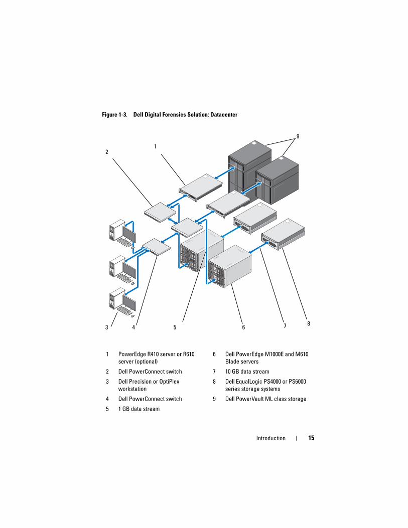
Figure 1-3. Dell Digital Forensics Solution: Datacenter
1 PowerEdge R410 server or R610
server (optional)
6 Dell PowerEdge M1000E and M610
Blade servers
2 Dell PowerConnect switch 7 10 GB data stream
3 Dell Precision or OptiPlex
workstation
8 Dell EqualLogic PS4000 or PS6000
series storage systems
4 Dell PowerConnect switch 9 Dell PowerVault ML class storage
5 1 GB data stream
311
412
513
614
715
816
19
210
EST
2
4
0
3
5
1
311
412
513
614
715
816
19
210
EST
2
4
0
3
5
1
3 54
2
7 8
1
9
6
16 Introduction
About This DocumentThis document covers each stage of the digital forensics process in its own chapter, with additional chapters on troubleshooting, hardware and software supported by the Solution. Each of the process chapters begins with a discussion of best practices and specific issues that you may encounter as you implement and manage the Solution, and then moves to a walk-through of the various tools and components relevant to that stage of the Solution.
Related Documentation and ResourcesYou can access additional information at support.dell.com/manuals.
Triage 17
Triage
What is Triage?Triage allows the digital forensics investigator to browse the data contained on suspect devices and to make decisions as to which devices are actually evidentiary and worth seizing for immediate imaging on site (if the data comprises a small volume) or for later imaging in the datacenter. This ability to preview and seize only select target devices can substantially reduce the delays that affect investigators’ ability to present evidence in a timely fashion. Triage can curtail the backlog of storage devices awaiting imaging back at the forensics lab, using fewer resources, avoiding adding to an already overloaded ingestion queue, and dramatically reducing operating costs.
Dell’s Triage Solution Advantage
Mobile
Dell’s Digital Forensics Solution can be at the crime scene with the investigator; all components have been thoroughly pre-tested to work together, and they cover a broad range of target device ports and connectors that you might expect to find in the field.
Fast
Existing forensic triage solutions can be slow and may even miss data because they perform tasks, such as keyword searches or hash matching during data collection. Dell’s Digital Forensics Solution overcomes this obstacle by using the computing power of the Dell ruggedized laptop rather than the target PC to perform analysis on the collected data. In some cases, you may be able to bypass imaging and indexing processes in the forensics lab altogether.
StoreIngest Store Analyze ArchivePresent
18 Triage
Easy to Use
The Triage components of the Solution are ready to use right out of the hardshell case. The pre installed software offers an intuitive touch screen interface. User defined, reusable collection profiles for different scenarios may be created for standard deployment.
Forensically Acceptable
Triage software enforces an efficient and forensically acceptable process, ensuring any potential evidence is captured, reviewed, and stored without compromise.
Flexible
The Triage components can be used to examine the most common digital storage devices and platforms, including devices running under both Windows and Apple’s Mac OS X operating systems, as well as a wide array of digital storage device types, such as MP3 players, external hard drives, memory cards, mobile and satellite phones, GPS units, iPads and iPhones, and flash drives. Furthermore, triage results using the Dell Digital Forensics Solution are exportable to other programs.
Powerful
The Dell ruggedized laptop controls the entire process from performing an automated analysis of targeted data to delivering detailed results in easy-to-use report format within a few minutes of data capture. Using the Dell Solution, the investigator will be able to run multiple triage scans in parallel with a single license key.
Triage 19
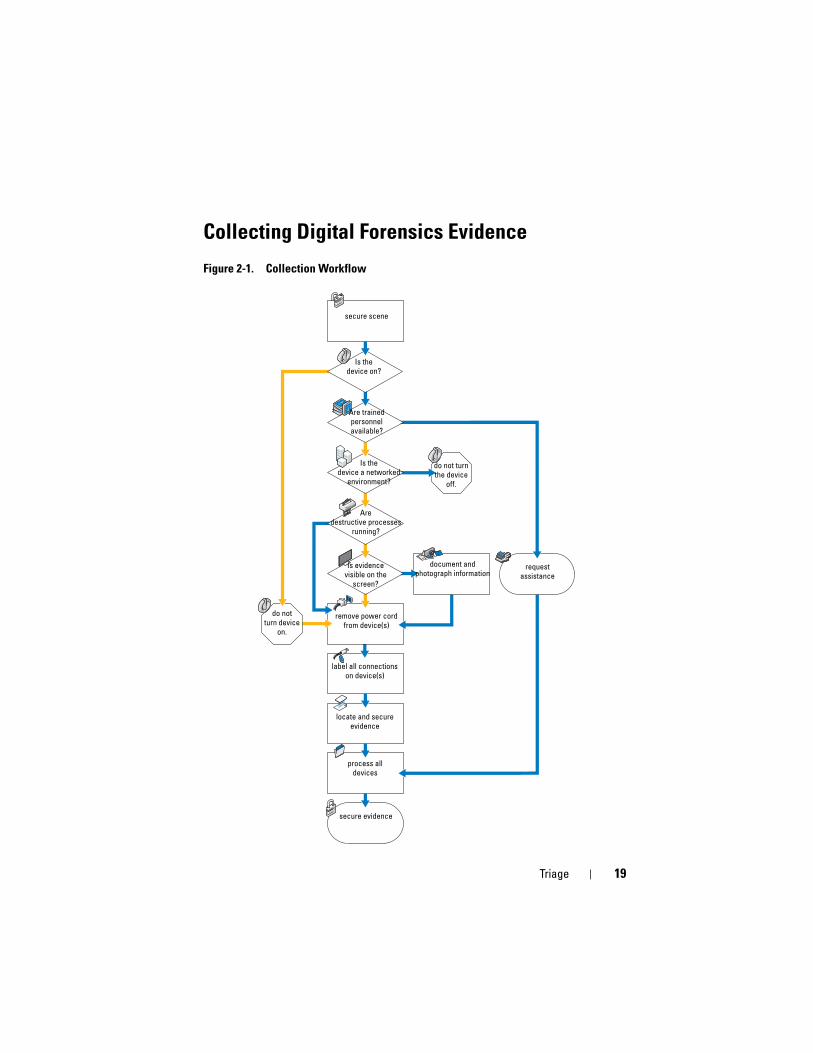
Collecting Digital Forensics Evidence
Figure 2-1. Collection Workflow
secure scene
Are trained personnel available?
do not turn the device
off.
document and photograph information
requestassistance
remove power cord from device(s)
label all connections on device(s)
locate and secure evidence
process all devices
secure evidence
Is the device on?
Is thedevice a networked
environment?
Aredestructive processes
running?
Is evidencevisible on the
screen?
do notturn device
on.
20 Triage
Standard vs. Live AcquisitionThe Dell Digital Forensics Solution offers two types of acquisition: Standard and Live. During a standard acquisition procedure, the Dell ruggedized laptop uses the SPEKTOR boot disk to capture triage data from an already powered-down target storage device. A live acquisition triage procedure, on the other hand, aims to capture triage data from a still powered-up target storage device, obtaining evidence not otherwise available.
Previously, industry standards required that the investigator unplug and seize a digital device for transport and examination back at the lab. This practice meant the loss of potentially valuable evidence in the form of stored volatile data: any data stored on the clipboard, currently open files, the contents of RAM, and cached passwords, etc. Additionally, encrypted data may be lost should the computer be shut down prior to imaging the disk. Furthermore, many computers have BIOS and hard drive passwords that are user-determined, and removing power from a live system with a BIOS password can cause loss of access to the entire content of the device.
Industry best practices require the investigator to approach a suspect data storage device with the following guidelines in mind:
• If the device is powered on, keep it on where possible until a thorough investigation can be performed.
• If the device is powered off, leave it off.
The reason for these guidelines is that the investigator must be careful to preserve the storage device as he finds it at the scene, and to introduce as little change as possible to the device and its contents.
How to Perform Triage Using the Dell Digital Forensics Solution
Turn on Your Dell Ruggedized Laptop
1 Press the power button to log on to the Dell ruggedized laptop. The laptop automatically loads the SPEKTOR software.
2 Tap or click Accept EULA. The Home screen opens.
Triage 21
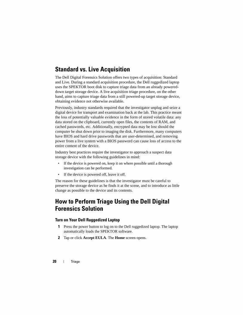
Figure 2-2. Home Screen
Burn a Boot CD for Standard Acquisition Procedures
1 At the Home screen, tap or click Admin. Then tap or click Burn Boot CD.
Figure 2-3. Burn Boot CD Button on the Home Screen
2 Follow the instructions on the screen, and then click Finish.
Register a Collector or Store Disk
NOTE: Collectors must be licensed and configured by SPEKTOR before they can be
used with your Dell Digital Forensics Solution. Contact your systems administrator if
you need additional Collectors or licenses.
1 Plug in a new Collector or store disk to one of the USB ports on the left hand side of the Dell ruggedized laptop. The device appears on the screen as an unrecognized device.
22 Triage
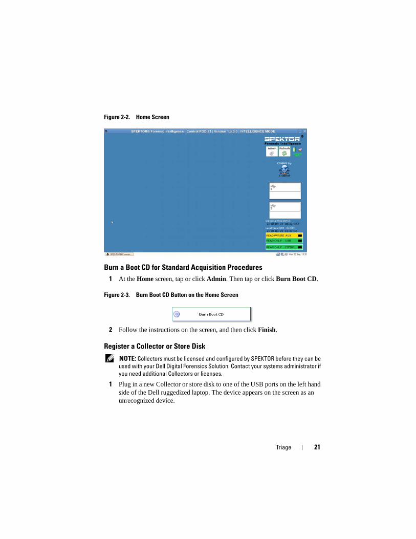
Figure 2-4. Unknown Collector or Store Disk Status Indicator
2 Tap or click the Status Indicator icon that corresponds to the Collector or store disk you plugged into the Dell ruggedized laptop. The icon for the device that has been registered will turn green (for a Collector) or orange (for a store disk).
3 The Unknown Device Menu will display.
Figure 2-5. Unknown Device Menu
4 Tap or click Register this device as a Collector or Register this device as a Store Disk.
5 Tap or click Yes.
The status indicator will show the new Collector or store disk number, and its status will change to Dirty.
Triage 23
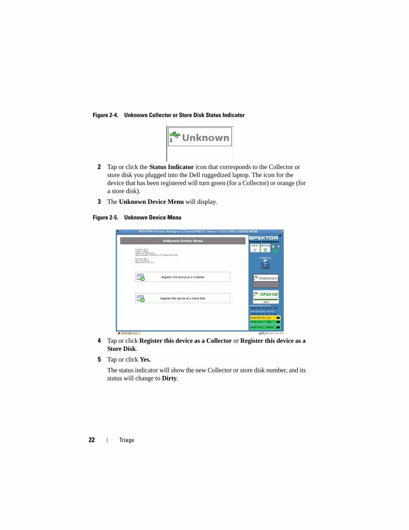
Figure 2-6. Dirty Collector and Store Disk Icons.
NOTE: Collectors and store disks, whether newly registered or previously used on
other data collections, must be cleaned before they can be deployed against a
target.
6 For a store disk only, enter the serial number of the store disk.
Clean a Collector or Store Disk
NOTE: Allow approximately two hours per 100 GB of Collector volume.
1 Select the Status Indicator representing the Collector you want to clean.
2 On the Collector Menu, tap or click Clean Collector.
3 Tap or click Yes to confirm your selection. Cleaning begins, and the Status Indicator will confirm the cleaning progress.
When cleaning has completed, the software will run a verification program to confirm that the only characters on the Collector drive are zeros.
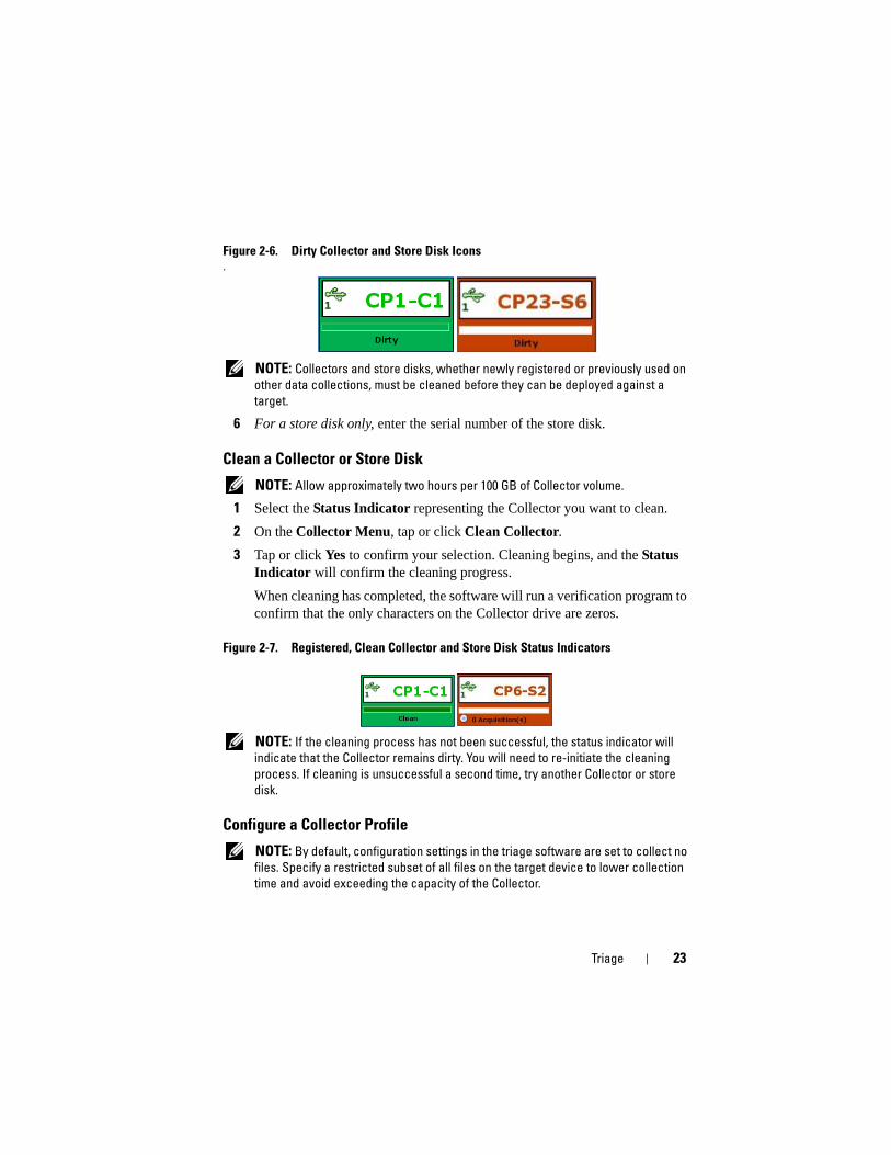
Figure 2-7. Registered, Clean Collector and Store Disk Status Indicators
NOTE: If the cleaning process has not been successful, the status indicator will
indicate that the Collector remains dirty. You will need to re-initiate the cleaning
process. If cleaning is unsuccessful a second time, try another Collector or store
disk.
Configure a Collector Profile
NOTE: By default, configuration settings in the triage software are set to collect no
files. Specify a restricted subset of all files on the target device to lower collection
time and avoid exceeding the capacity of the Collector.
24 Triage
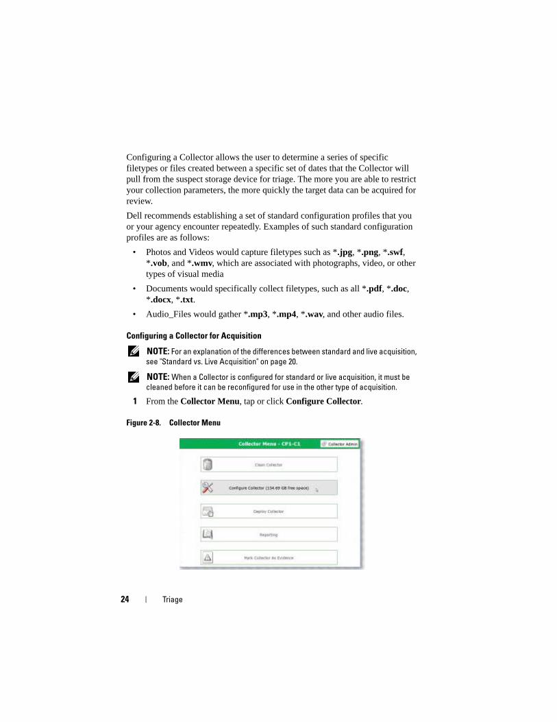
Configuring a Collector allows the user to determine a series of specific filetypes or files created between a specific set of dates that the Collector will pull from the suspect storage device for triage. The more you are able to restrict your collection parameters, the more quickly the target data can be acquired for review.
Dell recommends establishing a set of standard configuration profiles that you or your agency encounter repeatedly. Examples of such standard configuration profiles are as follows:
• Photos and Videos would capture filetypes such as *.jpg, *.png, *.swf, *.vob, and *.wmv, which are associated with photographs, video, or other types of visual media
• Documents would specifically collect filetypes, such as all *.pdf, *.doc, *.docx, *.txt.
• Audio_Files would gather *.mp3, *.mp4, *.wav, and other audio files.
Configuring a Collector for Acquisition
NOTE: For an explanation of the differences between standard and live acquisition,
see "Standard vs. Live Acquisition" on page 20.
NOTE: When a Collector is configured for standard or live acquisition, it must be
cleaned before it can be reconfigured for use in the other type of acquisition.
1 From the Collector Menu, tap or click Configure Collector.
Figure 2-8. Collector Menu
Triage 25
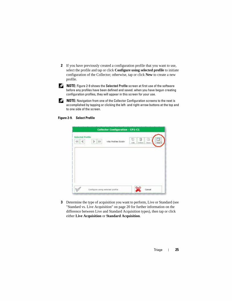
2 If you have previously created a configuration profile that you want to use, select the profile and tap or click Configure using selected profile to initiate configuration of the Collector; otherwise, tap or click New to create a new profile.
NOTE: Figure 2-9 shows the Selected Profile screen at first use of the software
before any profiles have been defined and saved. when you have begun creating
configuration profiles, they will appear in this screen for your use.
NOTE: Navigation from one of the Collector Configuration screens to the next is
accomplished by tapping or clicking the left- and right-arrow buttons at the top and
to one side of the screen.
Figure 2-9. Select Profile
3 Determine the type of acquisition you want to perform, Live or Standard (see "Standard vs. Live Acquisition" on page 20 for further information on the difference between Live and Standard Acquisition types), then tap or click either Live Acquisition or Standard Acquisition.
26 Triage
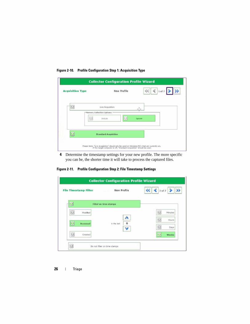
Figure 2-10. Profile Configuration Step 1: Acquisition Type
4 Determine the timestamp settings for your new profile. The more specific you can be, the shorter time it will take to process the captured files.
Figure 2-11. Profile Configuration Step 2: File Timestamp Settings
Triage 27
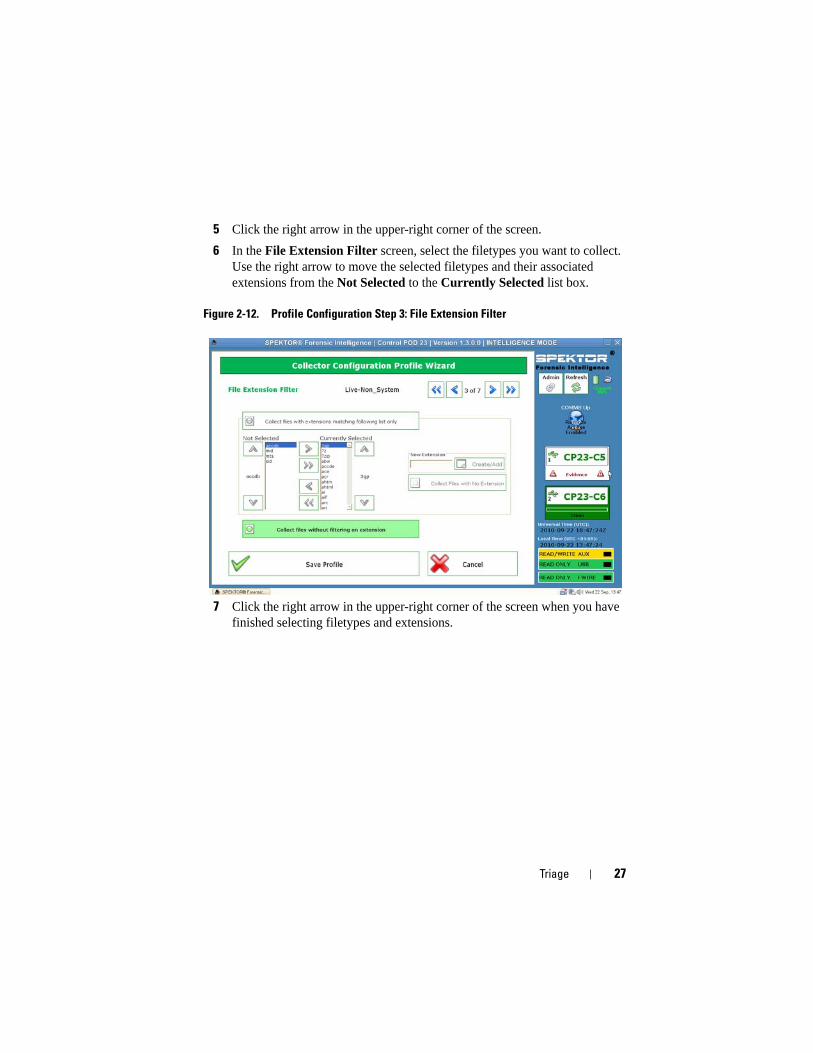
5 Click the right arrow in the upper-right corner of the screen.
6 In the File Extension Filter screen, select the filetypes you want to collect. Use the right arrow to move the selected filetypes and their associated extensions from the Not Selected to the Currently Selected list box.
Figure 2-12. Profile Configuration Step 3: File Extension Filter
7 Click the right arrow in the upper-right corner of the screen when you have finished selecting filetypes and extensions.
28 Triage
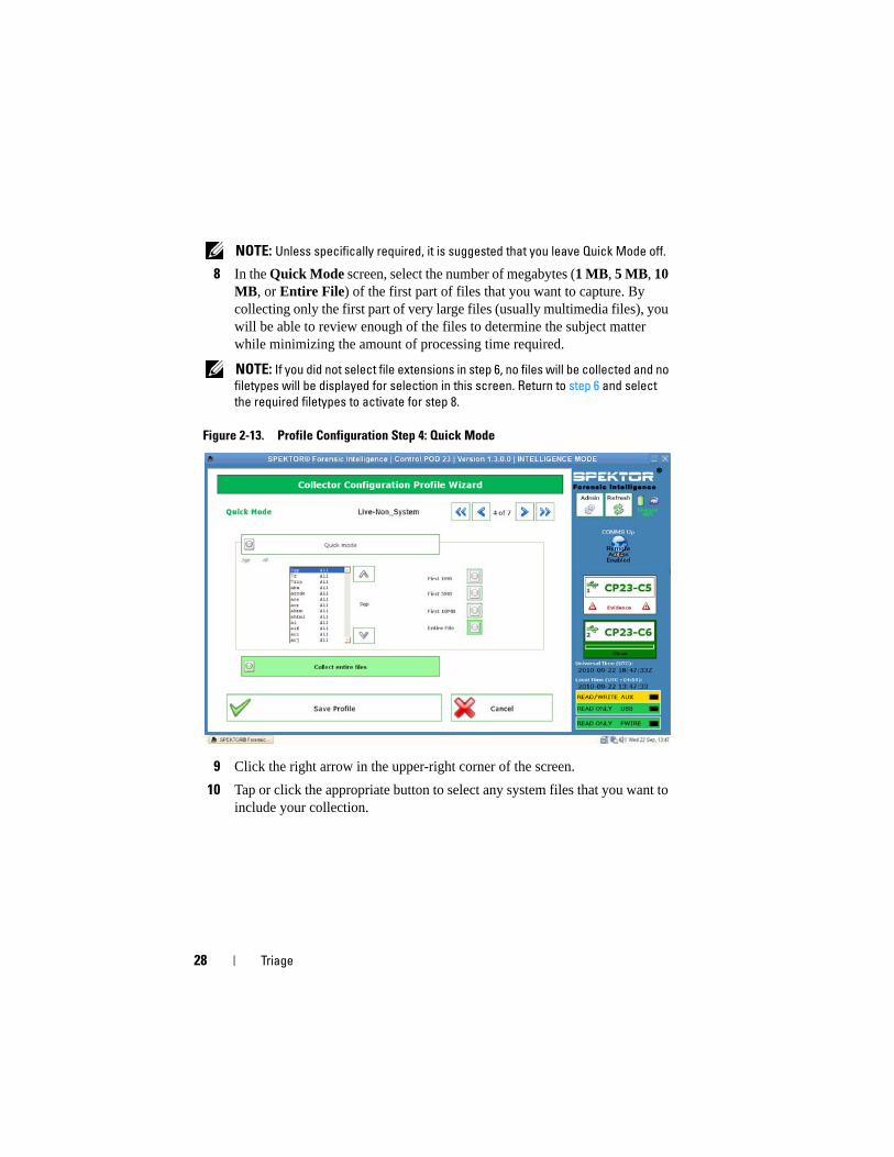
NOTE: Unless specifically required, it is suggested that you leave Quick Mode off.
8 In the Quick Mode screen, select the number of megabytes (1 MB, 5 MB, 10 MB, or Entire File) of the first part of files that you want to capture. By collecting only the first part of very large files (usually multimedia files), you will be able to review enough of the files to determine the subject matter while minimizing the amount of processing time required.
NOTE: If you did not select file extensions in step 6, no files will be collected and no
filetypes will be displayed for selection in this screen. Return to step 6 and select
the required filetypes to activate for step 8.
Figure 2-13. Profile Configuration Step 4: Quick Mode
9 Click the right arrow in the upper-right corner of the screen.
10 Tap or click the appropriate button to select any system files that you want to include your collection.
Triage 29
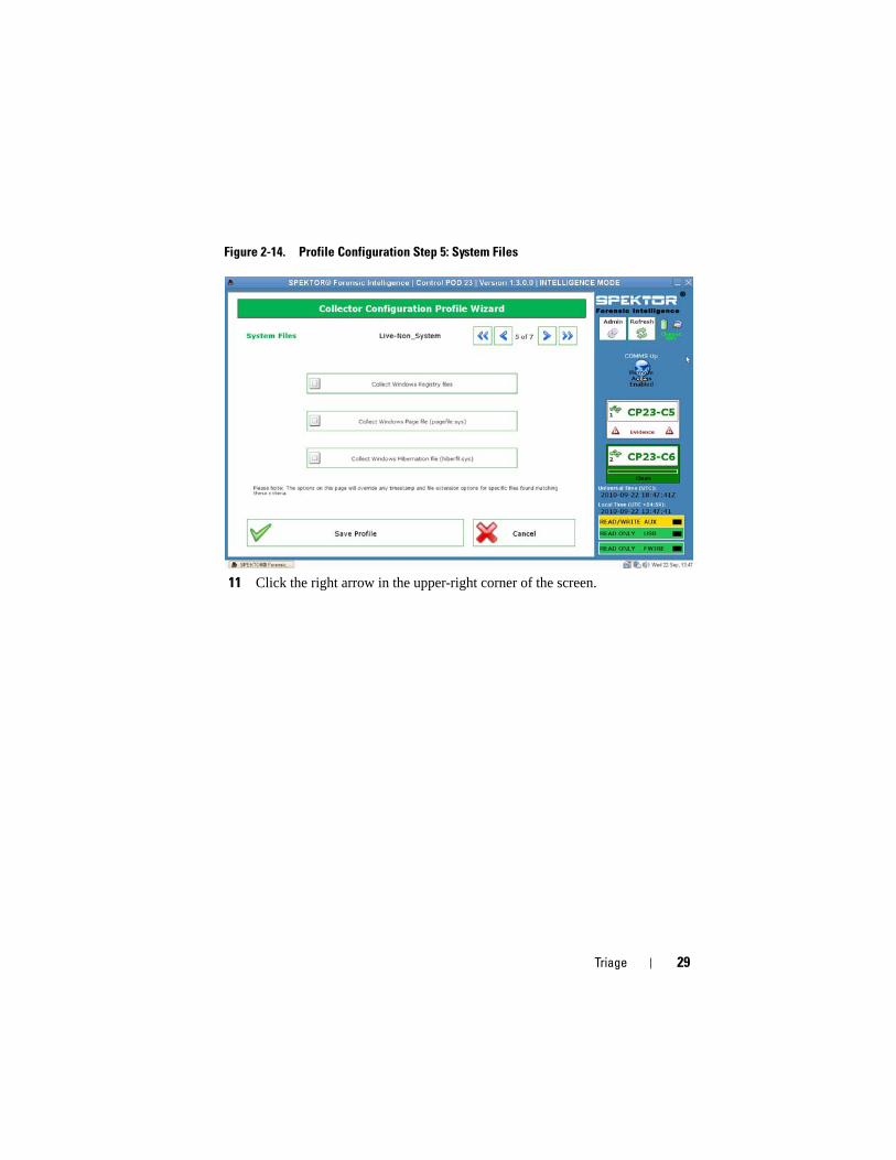
Figure 2-14. Profile Configuration Step 5: System Files
11 Click the right arrow in the upper-right corner of the screen.
30 Triage
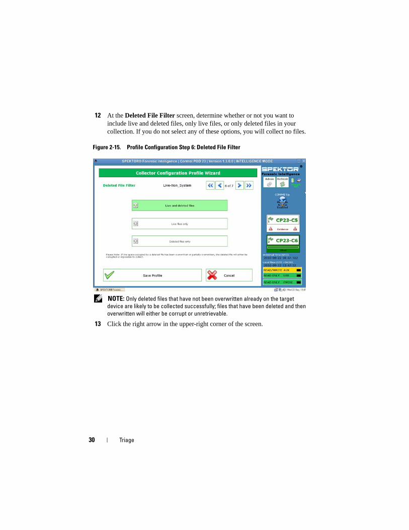
12 At the Deleted File Filter screen, determine whether or not you want to include live and deleted files, only live files, or only deleted files in your collection. If you do not select any of these options, you will collect no files.
Figure 2-15. Profile Configuration Step 6: Deleted File Filter
NOTE: Only deleted files that have not been overwritten already on the target
device are likely to be collected successfully; files that have been deleted and then
overwritten will either be corrupt or unretrievable.
13 Click the right arrow in the upper-right corner of the screen.
Triage 31
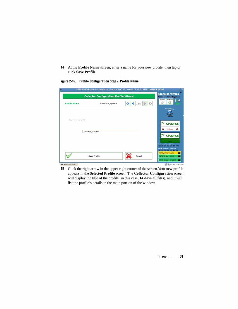
14 At the Profile Name screen, enter a name for your new profile, then tap or click Save Profile.
Figure 2-16. Profile Configuration Step 7: Profile Name
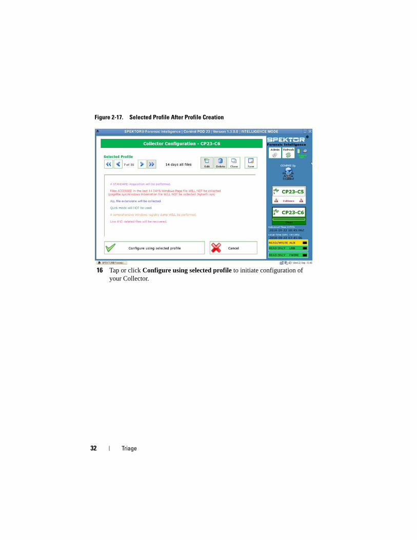
15 Click the right arrow in the upper-right corner of the screen.Your new profile appears in the Selected Profile screen. The Collector Configuration screen will display the title of the profile (in this case, 14 days all files), and it will list the profile’s details in the main portion of the window.
32 Triage
Figure 2-17. Selected Profile After Profile Creation
16 Tap or click Configure using selected profile to initiate configuration of your Collector.
Triage 33
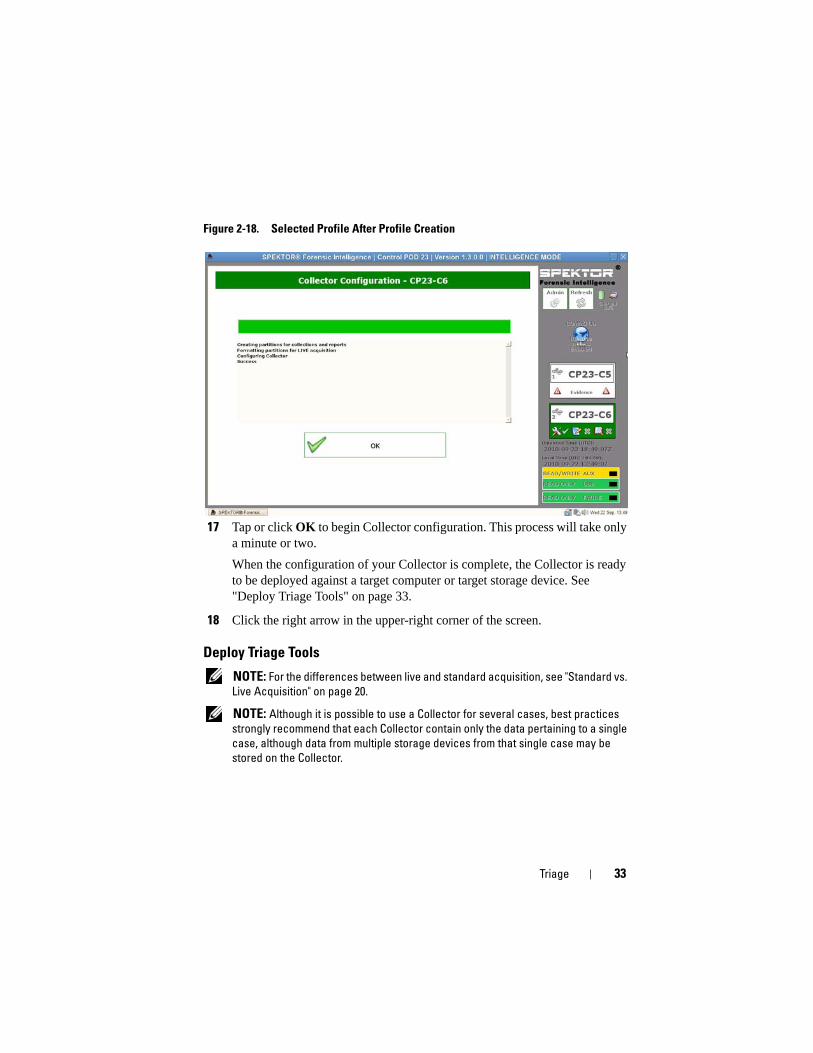
Figure 2-18. Selected Profile After Profile Creation
17 Tap or click OK to begin Collector configuration. This process will take only a minute or two.
When the configuration of your Collector is complete, the Collector is ready to be deployed against a target computer or target storage device. See "Deploy Triage Tools" on page 33.
18 Click the right arrow in the upper-right corner of the screen.
Deploy Triage Tools
NOTE: For the differences between live and standard acquisition, see "Standard vs.
Live Acquisition" on page 20.
NOTE: Although it is possible to use a Collector for several cases, best practices
strongly recommend that each Collector contain only the data pertaining to a single
case, although data from multiple storage devices from that single case may be
stored on the Collector.
34 Triage
Deploy a Collector for Standard Acquisition Against a Target Computer
WARNING: You must change the system boot order from within the target
computer’s system BIOS before attempting a standard acquisition. If the target
computer is set to boot from its hard drive instead of from the optical drive with the
SPEKTOR boot disk in place, the target computer’s drive contents will be altered.
Ensure that you know how to access the target computer system BIOS before
powering up the target computer.
WARNING: Before powering up the target computer, ensure that you have
placed the SPEKTOR boot disk in the optical drive to which the target computer is
set to boot. Failure to boot up the target computer without the boot disk in place
will result in the alteration of the target computer’s drive contents.
NOTE: You must have a SPEKTOR boot disk to accomplish a standard acquisition
deployment against a target computer. See "Burn a Boot CD for Standard
Acquisition Procedures" on page 21 for further information on creating a boot disk.
1 On the Dell ruggedized laptop, tap or click Deploy Collector.
2 Select Target Computer.
3 Click OK, then unplug the Collector from the Dell ruggedized laptop.
4 Plug in the Collector to an available USB port on the target computer.
NOTE: Dell recommends that you always use the target computer’s internal optical
drive with the boot disk. If this is not possible, use an external optical drive with a
USB connector.
5 Place the SPEKTOR boot disk in the optical drive.
6 Access the target computer’s system BIOS program and change the boot order so that the target computer will boot from the optical drive.
The SPEKTOR boot disk will load, and the boot drive interface will display.
7 Enter the information requested on the screen, pressing <Enter> or the arrow keys to move between fields, then move to the COLLECT field and press <Enter> to begin data collection.
CAUTION: Do not remove the SPEKTOR boot disk from the optical drive until the
target computer has shut down completely.
8 When the collection process is complete, press <Enter> to shut down the target computer.
Triage 35
9 Remove the SPEKTOR boot disk from the optical drive, unplug the Collector from the target computer’s USB port, and plug it into an available USB port on the Dell ruggedized laptop.
Deploy a Collector for Standard Acquisition Against a Target Storage Device
1 Plug the target storage device into either the read-only USB port or the firewire port of the Dell ruggedized laptop.
2 Tap or click Deploy Collector.
3 Tap or click Target Storage Device, enter the required information, then tap or click Collect from Device.
4 When the collection has completed, unplug the target storage device from the USB port and tap or click OK.
Deploy a Collector for Live Acquisition
NOTE: Ensure that you keep accurate and detailed notes during this procedure as
part of chain-of-custody best practices.
NOTE: You do not need the SPEKTOR Boot Disk to accomplish a live acquisition
deployment.
1 Click Deploy Collector→ Target Computer.
2 On the target device, navigate to My Computer (or Computer on those computers operating under Windows Vista or Windows 7).
3 Double-click Collector icon appears when it appears to view the contents of the Collector.
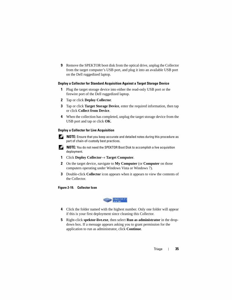
Figure 2-19. Collector Icon
4 Click the folder named with the highest number. Only one folder will appear if this is your first deployment since cleaning this Collector.
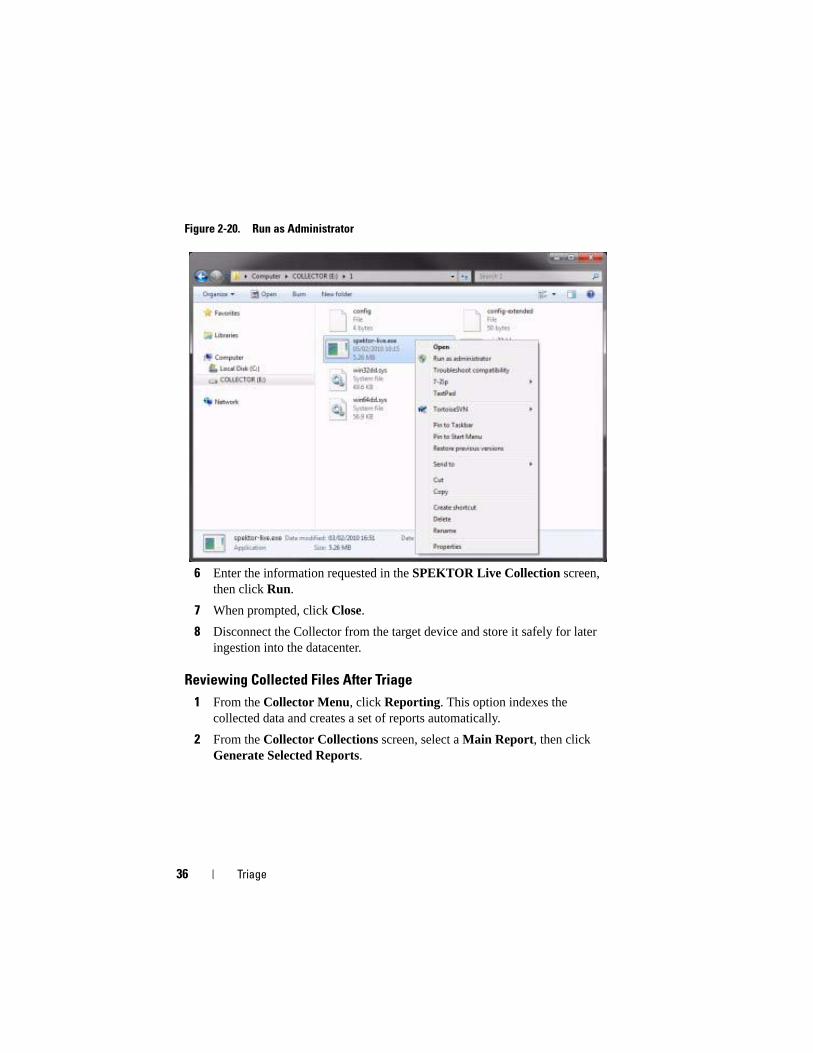
5 Right-click spektor-live.exe, then select Run as administrator in the drop-down box. If a message appears asking you to grant permission for the application to run as administrator, click Continue.
36 Triage
Figure 2-20. Run as Administrator
6 Enter the information requested in the SPEKTOR Live Collection screen, then click Run.
7 When prompted, click Close.
8 Disconnect the Collector from the target device and store it safely for later ingestion into the datacenter.
Reviewing Collected Files After Triage
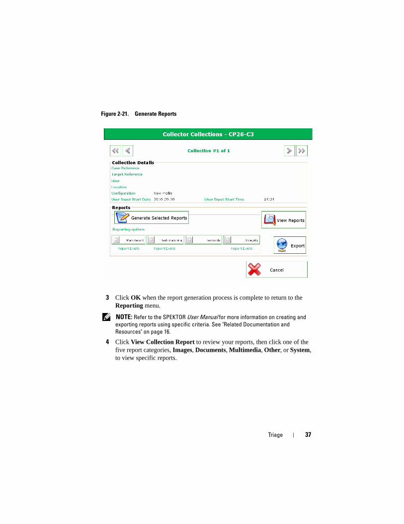
1 From the Collector Menu, click Reporting. This option indexes the collected data and creates a set of reports automatically.
2 From the Collector Collections screen, select a Main Report, then click Generate Selected Reports.
Triage 37
Figure 2-21. Generate Reports
3 Click OK when the report generation process is complete to return to the Reporting menu.
NOTE: Refer to the SPEKTOR User Manual for more information on creating and
exporting reports using specific criteria. See "Related Documentation and
Resources" on page 16.
4 Click View Collection Report to review your reports, then click one of the five report categories, Images, Documents, Multimedia, Other, or System, to view specific reports.

38 Triage
Ingest 39
Ingest
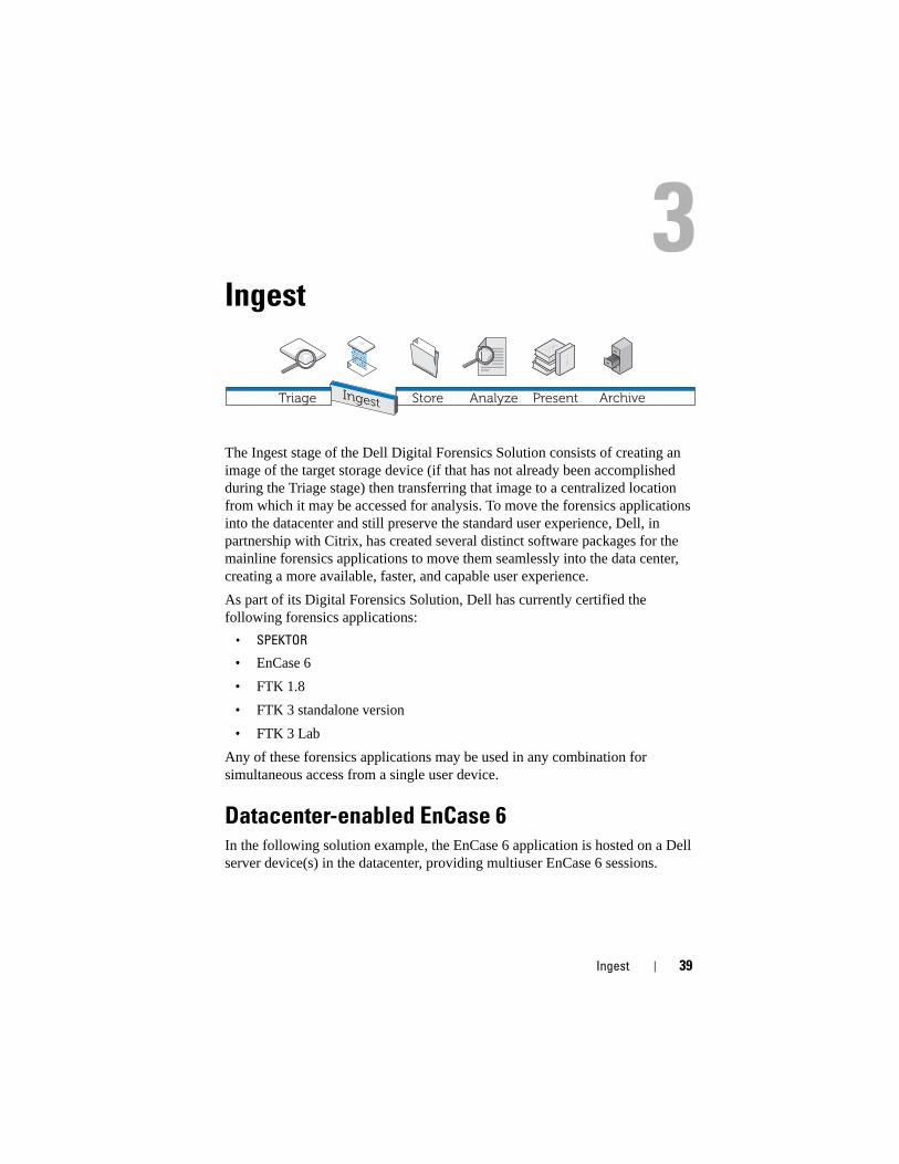
The Ingest stage of the Dell Digital Forensics Solution consists of creating an image of the target storage device (if that has not already been accomplished during the Triage stage) then transferring that image to a centralized location from which it may be accessed for analysis. To move the forensics applications into the datacenter and still preserve the standard user experience, Dell, in partnership with Citrix, has created several distinct software packages for the mainline forensics applications to move them seamlessly into the data center, creating a more available, faster, and capable user experience.
As part of its Digital Forensics Solution, Dell has currently certified the following forensics applications:
• SPEKTOR
• EnCase 6
• FTK 1.8
• FTK 3 standalone version
• FTK 3 Lab
Any of these forensics applications may be used in any combination for simultaneous access from a single user device.
Datacenter-enabled EnCase 6In the following solution example, the EnCase 6 application is hosted on a Dell server device(s) in the datacenter, providing multiuser EnCase 6 sessions.
Store Analyze ArchiveTriage Present
40 Ingest
Single-server Solution
In the single EnCase 6 server solution, multiple clients can connect to one server. All clients are pointed to this server and cannot connect to any other EnCase 6 server. In the event of a server failure, all client connections will be lost.
Multi-server Solution (High Availability)
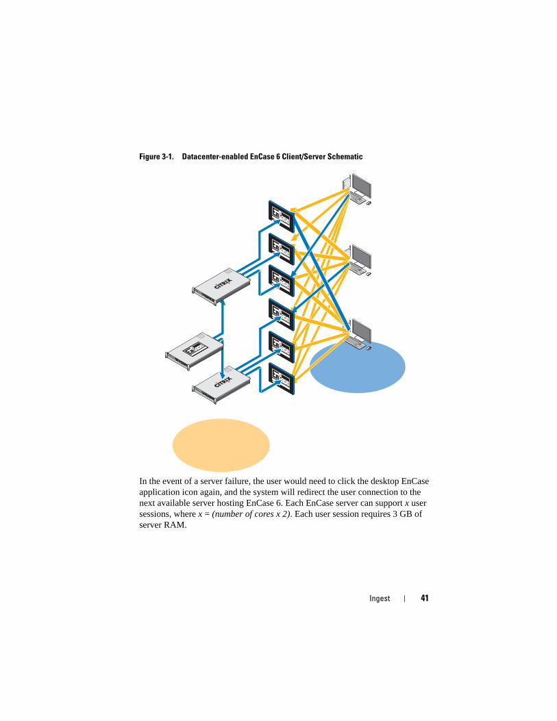
In the multiserver solution, a user will connect to the EnCase 6 application on the Citrix farm and will be directed seamlessly to the EnCase 6 server currently working with the lightest load. In the event that the user is running multiple instantiations of the EnCase 6 software, each instantiation could be created by a different server. The user experience would be preserved because the user would be totally unaware of the way multiple instances are created, and all sessions would appear to be running from the same server with the same look and feel.
Ingest 41
Figure 3-1. Datacenter-enabled EnCase 6 Client/Server Schematic
In the event of a server failure, the user would need to click the desktop EnCase application icon again, and the system will redirect the user connection to the next available server hosting EnCase 6. Each EnCase server can support x user sessions, where x = (number of cores x 2). Each user session requires 3 GB of server RAM.
EST
2
4
0
3
5
1
EST
2
4
0
3
5
1
EST
2
4
0
3
5
1
42 Ingest
Datacenter-enabled FTK 1.8In the Datacenter-enabled FTK 1.8 solution, the FTK 1.8 application is hosted on a Dell server device(s) in the datacenter, providing multiuser FTK 1.8 sessions (one unique user session per server).
Single FTK 1.8 Session Per Desktop
In the single server FTK 1.8 solution, multiple clients can connect to a single server. All clients are pointed to this server and cannot connect to any other FTK 1.8 server. In the event of a server failure, all client connections will be lost. The user can run only one session of FTK 1.8 per each Windows user account.
Multiple FTK 1.8 Sessions Per Desktop
In the multiserver FTK 1.8 solution, a user will connect to the FTK 1.8 servers by using multiple desktop icons FTK Server1, FTK Server2, etc. Each link is associated with a specific server. For illustration purposes, Figure 3-2 shows the border of the running FTK 1.8 server session as color-coded to the server running the session of FTK 1.8 (server1 = blue, server2 = red). Two sessions of the FTK 1.8 application cannot be run from the same server using the same user account. The server-based FTK 1.8 application user experience is the same across clients.
Ingest 43
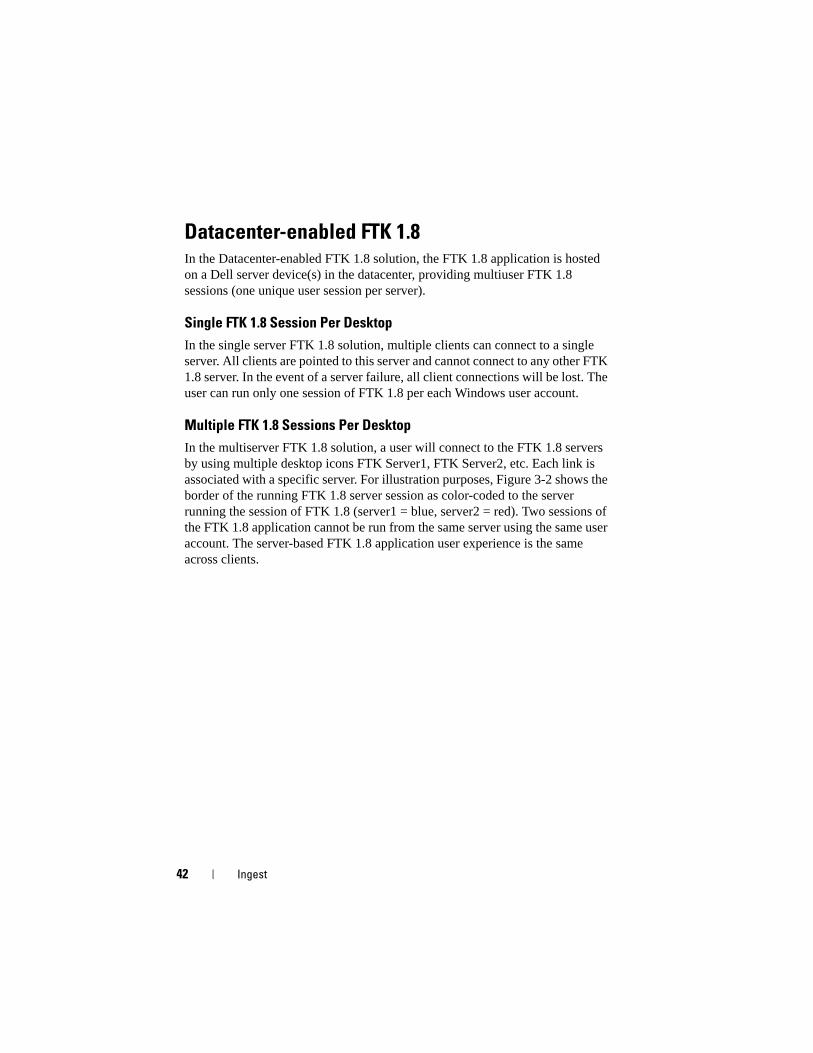
Figure 3-2. Multiple FTK 1.8 Client and Server Schematic
In the event of a server failure, the user would lose access to the corresponding server session of FTK 1.8. In this case, the user would need to continue to function using the other FTK servers. All case and evidence information (assuming the user has NAS access privileges) is available from all server sessions of FTK 1.8 through the shared NAS/SAN.
Each FTK 1.8 server can support x user sessions, where x = (number of cores x 2). Each user session requires 3 GB of server RAM and 1000 I/O per second of datacenter disk performance.
Datacenter-enabled FTK 3In the datacenter-enabled FTK 3 solution, the application is hosted on a Dell server device(s) in the datacenter, providing a single FTK 3 application session per server.
EST
2
4
0
3
5
1
EST
2
4
0
3
5
1
EST
2
4
0
3
5
1
44 Ingest
Single FTK 3 Server Solution
In the single FTK 3 server solution, a single FTK 3 client can connect to a single server. The client is pointed to this server and cannot connect to any other FTK 3 server. In the event of a server failure, the client connection will be lost. The FTK 3 server will also be running the local FTK embedded Oracle database because this version of the database does not support collaboration between other FTK Oracle databases or other FTK users.
Multiserver Solution (No High Availability)
In the multiserver solution, each client will connect to their home FTK 3 server and cannot connect to any to other FTK 3 server. When a server has a session of FTK 3 running, it is no longer available to accept any new FTK 3 client session: the software setup in the Dell forensic framework makes it impossible for a server to run more than one session of the FTK 3 application simultaneously. By allowing only one session to run per server, the multithreaded FTK 3 application is able to devote all available server resources to processing a case, thus improving performance.
Ingest 45
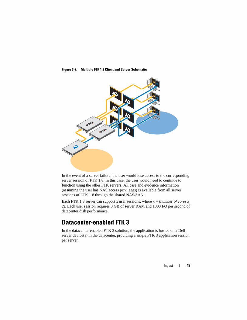
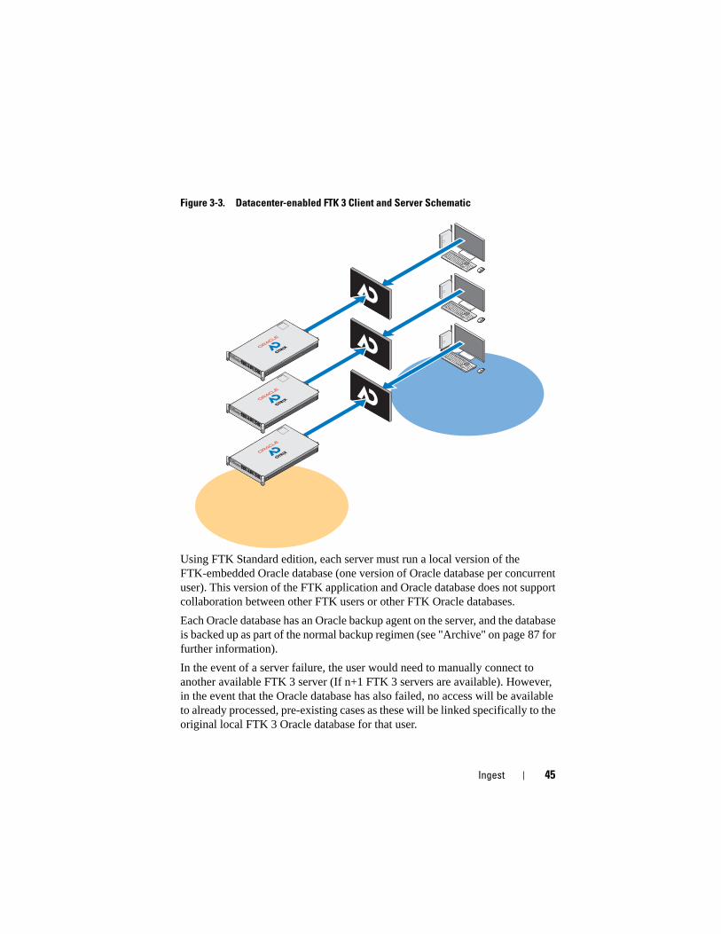
Figure 3-3. Datacenter-enabled FTK 3 Client and Server Schematic
Using FTK Standard edition, each server must run a local version of the FTK-embedded Oracle database (one version of Oracle database per concurrent user). This version of the FTK application and Oracle database does not support collaboration between other FTK users or other FTK Oracle databases.
Each Oracle database has an Oracle backup agent on the server, and the database is backed up as part of the normal backup regimen (see "Archive" on page 87 for further information).
In the event of a server failure, the user would need to manually connect to another available FTK 3 server (If n+1 FTK 3 servers are available). However, in the event that the Oracle database has also failed, no access will be available to already processed, pre-existing cases as these will be linked specifically to the original local FTK 3 Oracle database for that user.
EST
2
4
0
3
5
1
EST
2
4
0
3
5
1
EST
2
4
0
3
5
1
46 Ingest
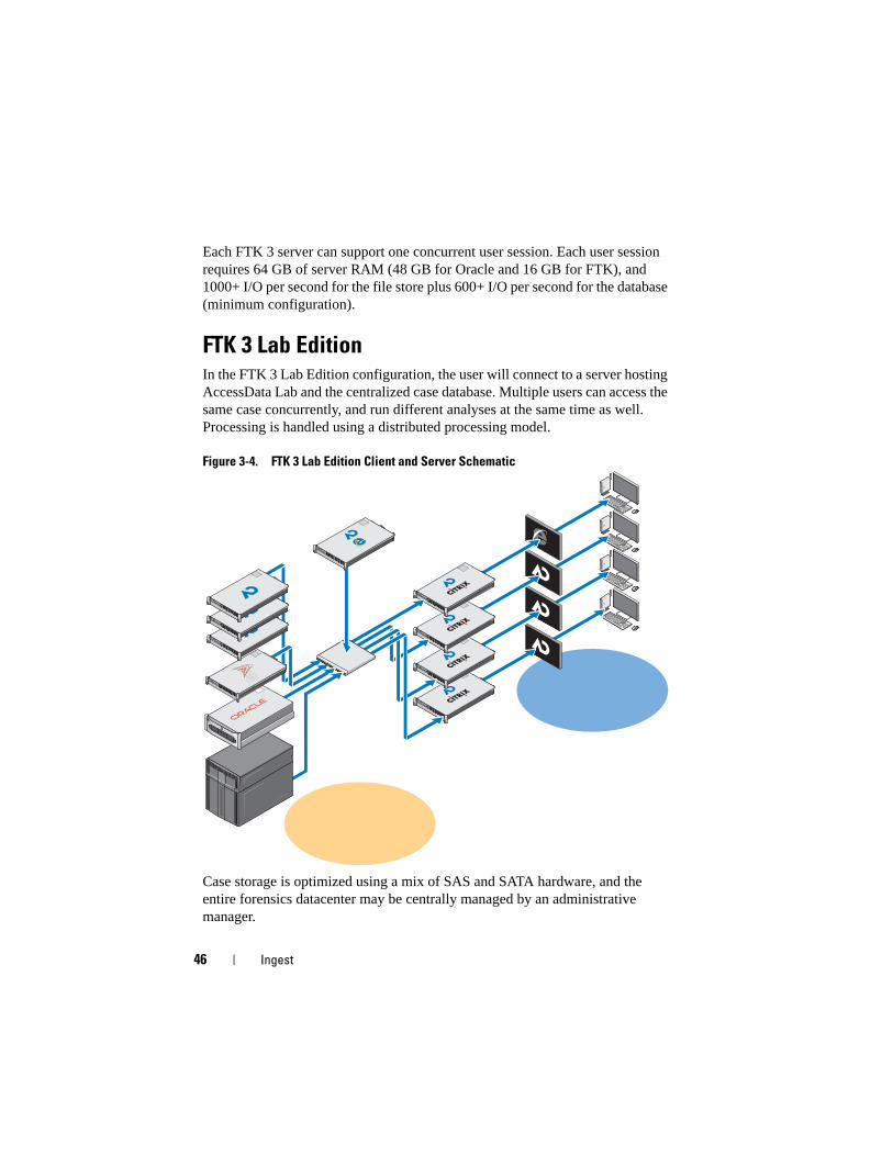
Each FTK 3 server can support one concurrent user session. Each user session requires 64 GB of server RAM (48 GB for Oracle and 16 GB for FTK), and 1000+ I/O per second for the file store plus 600+ I/O per second for the database (minimum configuration).
FTK 3 Lab EditionIn the FTK 3 Lab Edition configuration, the user will connect to a server hosting AccessData Lab and the centralized case database. Multiple users can access the same case concurrently, and run different analyses at the same time as well. Processing is handled using a distributed processing model.
Figure 3-4. FTK 3 Lab Edition Client and Server Schematic
Case storage is optimized using a mix of SAS and SATA hardware, and the entire forensics datacenter may be centrally managed by an administrative manager.
EST
2
4
0
3
5
1
EST
2
4
0
3
5
1
EST
2
4
0
3
5
1
EST
2
4
0
3
5
1
EST
2
4
0
3
5
1
EST
2
4
0
3
5
1
EST
2
4
0
3
5
1
EST
2
4
0
3
5
1
EST
2
4
0
3
5
1
Ingest 47
Multiple Forensics Applications Delivered to One DesktopIn the multivendor and multiapplication solution, all of the individual application solutions described previously are combined to provide the forensics analyst with access to all forensics applications (EnCase 6, FTK 1.8 and FTK 3, or FTK 3 Lab edition) from a single desktop, a single pane of glass. All applications can be delivered in a high availability mode so that in the event of a failure, the user still has access to that specific application; and in the case of FTK 1.8, the user has access by using one of the other FTK 1.8 icons on the desktop.
48 Ingest
Network Configuration Recommendations
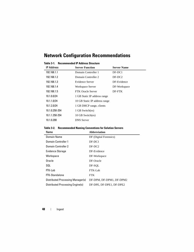
Table 3-1. Recommended IP Address Structure
Table 3-2. Recommended Naming Conventions for Solution Servers
IP Address Server Function Server Name
192.168.1.1 Domain Controller 1 DF-DC1
192.168.1.2 Domain Controller 2 DF-DC2
192.168.1.3 Evidence Server DF-Evidence
192.168.1.4 Workspace Server DF-Workspace
192.168.1.5 FTK Oracle Server DF-FTK
10.1.0.0/24 1 GB Static IP address range
10.1.1.0/24 10 GB Static IP address range
10.1.2.0/24 1 GB DHCP range, clients
10.1.0.250-254 1 GB Switch(es)
10.1.1.250-254 10 GB Switch(es)
10.1.0.200 DNS Server
Name Abbreviation
Domain Name DF (Digital Forensics)
Domain Controller 1 DF-DC1
Domain Controller 2 DF-DC2
Evidence Storage DF-Evidence
Workspace DF-Workspace
Oracle DF-Oracle
SQL DF-SQL
FTK-Lab FTK-Lab
FTK-Standalone FTK
Distributed Processing Manager(s) DF-DPM, DF-DPM1, DF-DPM2
Distributed Processing Engine(s) DF-DPE, DF-DPE1, DF-DPE2
Ingest 49
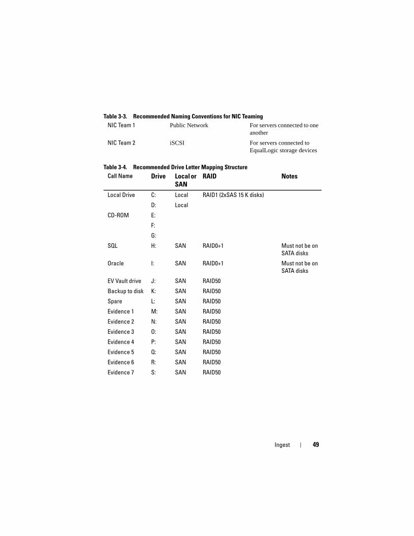
Table 3-3. Recommended Naming Conventions for NIC Teaming
Table 3-4. Recommended Drive Letter Mapping Structure
NIC Team 1 Public Network For servers connected to one another
NIC Team 2 iSCSI For servers connected to EqualLogic storage devices
Call Name Drive Local or
SAN
RAID Notes
Local Drive C: Local RAID1 (2xSAS 15 K disks)
D: Local
CD-ROM E:
F:
G:
SQL H: SAN RAID0+1 Must not be on
SATA disks
Oracle I: SAN RAID0+1 Must not be on
SATA disks
EV Vault drive J: SAN RAID50
Backup to disk K: SAN RAID50
Spare L: SAN RAID50
Evidence 1 M: SAN RAID50
Evidence 2 N: SAN RAID50
Evidence 3 O: SAN RAID50
Evidence 4 P: SAN RAID50
Evidence 5 Q: SAN RAID50
Evidence 6 R: SAN RAID50
Evidence 7 S: SAN RAID50
50 Ingest
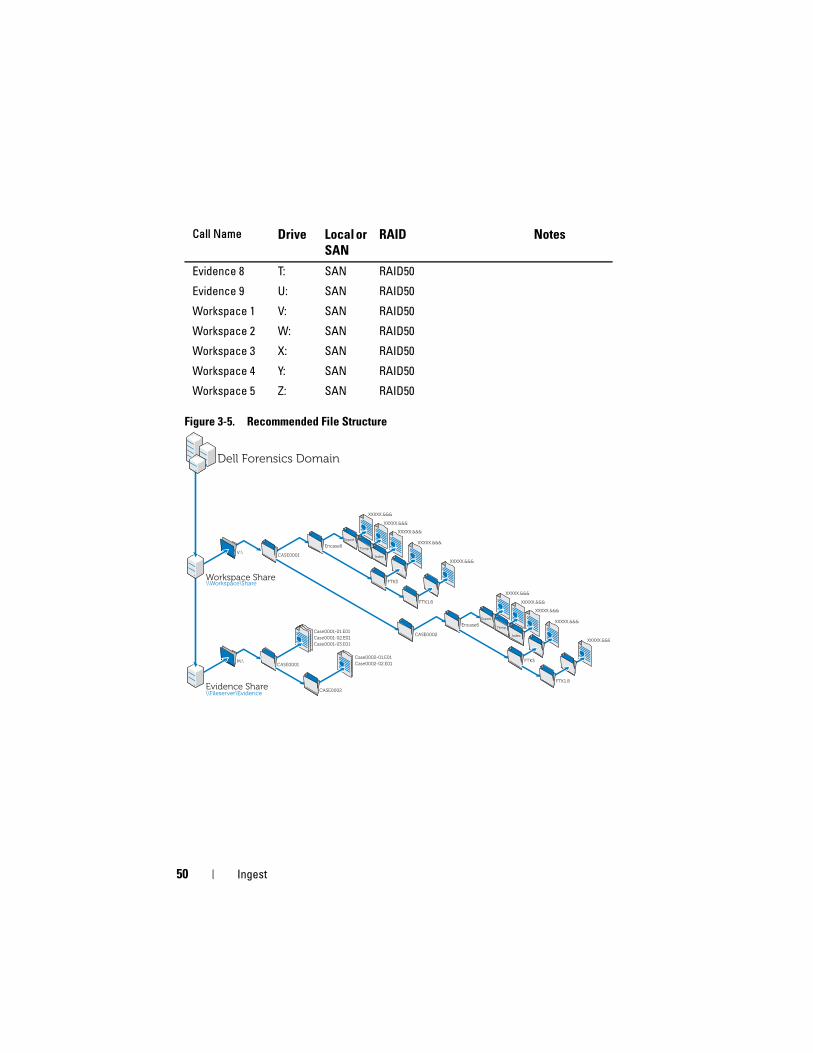
Figure 3-5. Recommended File Structure
Evidence 8 T: SAN RAID50
Evidence 9 U: SAN RAID50
Workspace 1 V: SAN RAID50
Workspace 2 W: SAN RAID50
Workspace 3 X: SAN RAID50
Workspace 4 Y: SAN RAID50
Workspace 5 Z: SAN RAID50
Call Name Drive Local or
SAN
RAID Notes
Evidence Share\\Fileserver\Evidence
CASE0001
CASE0002
Case0001-01.E01
Case0001-02.E01
Case0001-03.E01
Case0002-01.E01
Case0002-02.E01
Dell Forensics Domain
Workspace Share\\Workspace\Share
CASE0001
CASE0002
Encase6
FTK3
FTK1.8
Encase6
FTK3
FTK1.8
V:\
M:\
Export
Temp
Index
Export
Temp
Index
XXXXX.&&&
XXXXX.&&&
XXXXX.&&&
XXXXX.&&&
XXXXX.&&&
XXXXX.&&&
XXXXX.&&&
XXXXX.&&&
XXXXX.&&&
XXXXX.&&&
Ingest 51
How to Perform Ingest Using the Dell Digital Forensics Solution
Ingest Using SPEKTOR
Register and Clean an External USB Device as a Store Disk
1 Plug the unregistered external USB device in a Collector port on the ruggedized laptop.
2 Click or tap the device icon when it appears; then click or tap Register the Device as a Store Disk→ Yes. Then enter the requested information.
3 From the right-hand menu, select the registered device; then tap or click Clean/Reformat→ Clean.
4 Click OK when the process completes.
Deploy the Store Disk
1 Plug in the store disk to the ruggedized laptop; then tap or click the store disk device to display the Store Disk Menu.
2 In the Store Disk Menu, tap or click Deploy.
If you are deploying against a target computer:
a Tap or click Target Computer.
b Remove the storage disk from the ruggedized laptop, and plug it into a spare USB port on the target computer.
c Follow the same deployment instructions as for capturing a triage image in "Deploy Triage Tools" on page 33.
d When the boot CD is loaded, the SPEKTOR Imaging Wizard will walk you through the remainder of the imaging process. Step-by-step instructions may be found in the SPEKTOR User Manual. See "Related Documentation and Resources" on page 16 for more information.
e Shut down the target computer, unplug the store disk, and then return the store disk to the datacenter for storage.
If you are deploying against a target storage device locally:
a Tap or click Target Storage Device.
52 Ingest
b Plug the target storage device into either the Read Only USB port or the FireWire port on the right-hand side of the ruggedized laptop.
c Select the drive or partitions you want to image, and then click the right arrow in the upper-right corner of the screen.
d Enter the case information requested, and then tap or click Image Now.
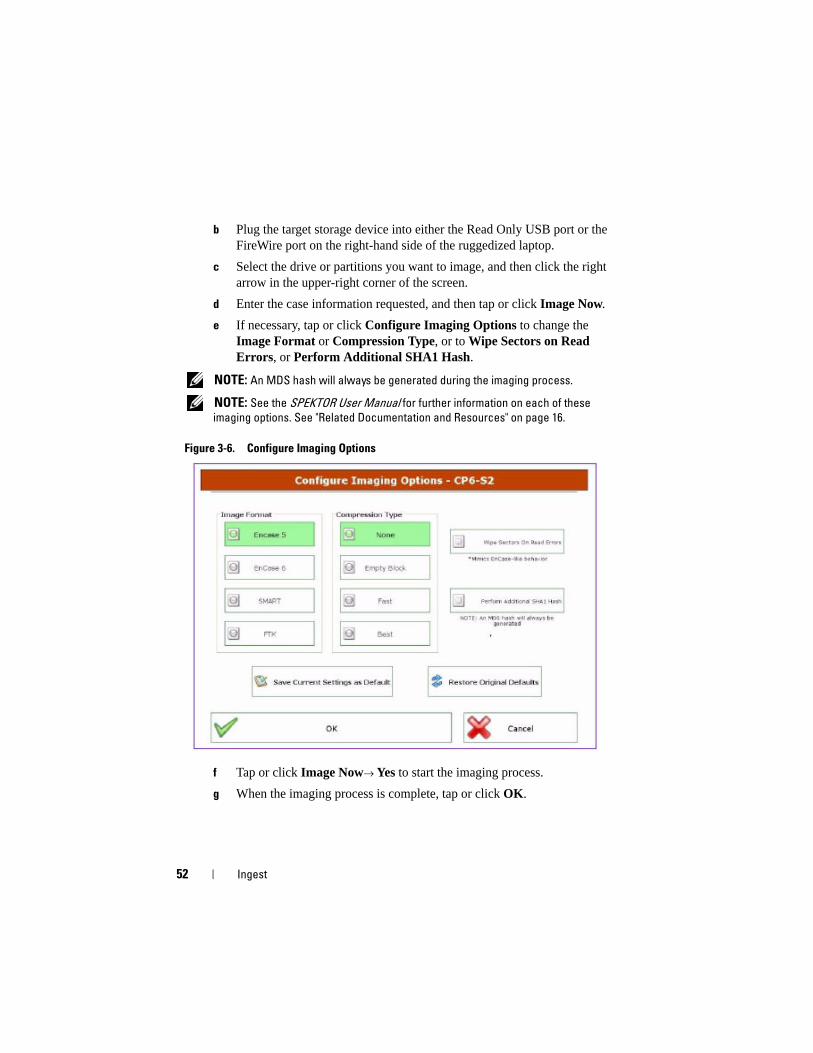
e If necessary, tap or click Configure Imaging Options to change the Image Format or Compression Type, or to Wipe Sectors on Read Errors, or Perform Additional SHA1 Hash.
NOTE: An MDS hash will always be generated during the imaging process.
NOTE: See the SPEKTOR User Manual for further information on each of these
imaging options. See "Related Documentation and Resources" on page 16.
Figure 3-6. Configure Imaging Options
f Tap or click Image Now→ Yes to start the imaging process.
g When the imaging process is complete, tap or click OK.
Ingest 53
h Unplug the target storage device and the store disk from the ruggedized laptop; then return the store disk to the datacenter for storage and analysis.
NOTE: Transferring an image may take a long time; six hours for a typical 60 GB
hard drive transfer is not unusual.
Ingest Using EnCase
In the Dell Digital Forensics Solution, licensing for EnCase is accomplished using a network licensing system. Typically, an instance of EnCase SAFE is installed on one of the datacenter servers, and a dongle containing multiple user licenses is connected to that server. EnCase clients are configured to look to that server for licensing, and no local dongles are required. See the Dell Digital Forensics Installation and Configuration Guide for further information. See "Related Documentation and Resources" on page 16. Also, see your network systems administrator for information specific to your agency’s Solution installation.
1 Attach the target storage device to the appropriate ingest workstation in the datacenter.
a If you are imaging a SATA drive, see "Connecting the Tableau Write-Blocker to a SATA Hard Drive" on page 55 for further information.
b If you are imaging an IDE drive, see "Connecting the Tableau Write-Blocker to an IDE Hard Drive" on page 55 for further information.
2 Create a new case.
NOTE: The following instructions refer to the network and folder structure outlined
as Dell’s suggested best practice for its Digital Forensics Solution; see Figure 3-5 for
further information.
a Click New, and then enter the information requested.
b On the W:\ drive (work area), create folders using the following structure:
• W:\[CaseName]\EnCase6\Export
• W:\[CaseName]\EnCase6\Temp
• W:\[CaseName]\EnCase6\Index
c Click Finish.
d Click Yes for each request to create the folder.
54 Ingest
e In the EnCase Acquisition screen, click the Add Device menu option.
f Ensure that the Sessions checkbox is checked.
g In the right-hand pane, select your case.
h Click Add Evidence Files; then navigate to the E01 repository (using the best practice configuration outlined in Figure 3-5, this repository should be stored on drive X:\).
i Click Next→ Next→ Finish. A stopwatch icon appears in the lower-right portion of the EnCase Acquisition screen, and EnCase will verify the E01 file. Depending on the file size, the verification may take some time.
3 Within the EnCase software, add the target storage device using the Add Device wizard.
4 Acquire your device content.
a From within the EnCase software, click Cases→ Entries→ Home; then right-click the device you want to acquire.
b Select Acquire from the drop-down menu.
c In the After Acquisition dialogue box, select the appropriate New Image File type:
• Do not add the options that exclude the newly-acquired image from the case currently open.
• Add to Case adds the newly-acquired image in the case file associated with the device where the image was taken.
• Replace a source device adds the newly-acquired image to the case and removes the previewed device where the acquisition was made.
d Click Finish. When the imaging process is complete, the Acquisition Results dialog box will be displayed.
Working with Tableau Write-Blockers
CAUTION: Do not remove a hard drive from a forensic bridge while the power is
on.
CAUTION: Do not use USB cable extenders with any forensic bridge.

Ingest 55
Connecting the Tableau Write-Blocker to a SATA Hard Drive
1 Ensure the T35es Forensic SATA/IDE bridge's DC IN B is in the B On position.
2 Connect the TP2 or TP3 power source to the left side of the T35es SATA bridge using the 5-pin Mini-DIN connector.
3 Connect the power cable to the TP2 power source and also into an electrical socket.
4 Turn the power on to verify that the write block LED is on; then turn off the power to the bridge prior to connecting to the target storage device.
5 Connect the female Molex connector of the TC5-8 SATA-Style power cable to the DC OUT position located on the right side of the T35es SATA/IDE bridge.
6 Connect the SATA power connector of the TC5-8 SATA-Style power cable to the target hard drive’s SATA power connector.
CAUTION: Using both Molex and SATA power connections when connecting to a
target storage device will overload the target device.
7 Connect the TC3-8 SATA signal cable to the T35es SATA/IDE bridge.
8 Connect the other end of the TC3-8 SATA Signal Cable to the target storage device.
9 Plug one end of the data cable (USB 2.0, two Fire Wire 800 connections, or Orion 4-pin FireWire 400) to one of the ports on the left side of the T35es SATA/IDE bridge.
10 Plug the other end of the data cable to a port on the Dell ruggedized laptop or on the Dell OptiPlex workstation.
11 Flip the switch on the top of the T35es SATA/IDE bridge to the A ON position. The Dell ruggedized laptop or Dell OptiPlex workstation should now register the presence of the target storage device.
Connecting the Tableau Write-Blocker to an IDE Hard Drive
1 Ensure the T35es Forensic SATA/IDE bridge's DC IN B is in the B On position.
2 Connect the TP2 or TP3 power source to the left side of the T35es SATA/IDE bridge via the 5-pin Mini-DIN connector.
56 Ingest
NOTE: The 7-Pin DIN plug on the TP3 Power Supply will not work with the Tableau
bridges. You must use the included 7-pin DIN to 5-pin DIN TCA-P7-P5 adapter cable
to connect the TP3 power supply to the Tableau bridges.
3 Connect the power cable to the TP2 power source and also into an electrical socket.
4 Turn the power on to verify that the write block LED is ON; then turn the power to the bridge OFF before connecting to the target hard drive.
5 Connect one female Molex connector of the TC2-8 Molex-style Power cable to the DC OUT located on the right side of the T35es SATA/IDE bridge.
6 Connect the other female Molex connector of the TC2-8 Molex-style power cable to the suspect hard drive's Molex connector.
7 Connect the blue end of the TC6-8 IDE Signal Cable (so as to align pin 1) to the T35es SATA/IDE bridge.
8 Connect the black end of the TC6-8 IDE Signal Cable to the target storage device.
9 Plug one end of the data cable (USB 2.0, two FireWire 800 connections, Orion 4-pin FireWire 400 connection) to one of the ports on the left side of the T35es SATA bridge.
10 Plug the other end of the data cable to a port on the Dell ruggedized laptop or Dell OptiPlex workstation.
11 Flip the switch on the top of the T35es SATA/IDE bridge to the A On position. The Dell ruggedized laptop or Dell OptiPlex workstation should recognize the presence of the target storage device.
Ingest Using FTK 1.8 and 3.0 Datacenter-enabled
In the Dell Digital Forensics Solution, licensing for FTK is accomplished using a network licensing system. Typically, the FTK Network Licensing Server is installed on one of the datacenter servers, and an FTK dongle containing multiple user licenses is plugged into that server. The FTK clients are configured to look to that server for licensing, and no local dongles are required. See the Dell Digital Forensics Installation and Configuration Guide for further information. See "Related Documentation and Resources" on page 16. Also, see your network systems administrator for information specific to your agency’s Solution installation.

Ingest 57
Create an Image of the Target Storage Device
1 Within the AccessData FTK Imager application, click File→ Create Disk Image . . .
2 In the Select Source pop-up, select the type of evidence you want to image: Physical Drive, Logical Drive, Image File, Contents of a Folder, or Fernico Device, and click Next.
NOTE: The following uses the Imaging a Physical Drive option to demonstrate the image creation process.The other file options are covered in the FTK User’s Guide. See "Related Documentation and Resources" on page 16.
3 Using the drop-down box, select the physical drive you want to image from the available drives, then click Finish.
4 In the Create Image pop-up, click Add . . . and select the type of image you want to create (Raw, SMART, E01, or AFF). Then click Next.
5 Enter the requested information in the Evidence Item Information window (Case Number, Evidence Number, Unique Description, Examiner, and Notes). Then click Next.
6 In the Select Image Destination window, browse to the storage area allocated for evidence images (see Figure 3-5 for Dell’s recommended file and server nomenclature), enter an image filename, and then click →
7 Click Start. The Creating Image . . . pop-up appears and provides a progress bar of the operation.
NOTE: The image creation process can take hours depending on the volume of data being added.
8 If you opted earlier to view a summary of the image results, the Drive/Image Verify Results window will appear when the image creation process completes. Review the results, and then click Close.
9 Click Close again to close the Creating Image . . . window.
Create a Case
1 Click File→ New Case. Enter the following: Investigator Name, Case Number, Case Name, Case Path, and Case Folder.
2 In the Forensic Examiner Information window, enter the following: Agency/Company, Examiner’s Name, Address, Phone, Fax, E-Mail, and Comments. Then click Next.
58 Ingest
3 In the Case Log Options window, select the set of options you want to change:
• Case and evidence events
• Error messages
• Bookmarking events
• Searching events
• Data carving/Internet searches
• Other events
4 In the Processes to Perform window, select the processes you want to conduct. Select the Processes from the following options:
• MD5 Hash
• SHA1 Hash
• KFF Lookup
• Entropy Test
• Full Text Index
• Store Thumbnails
• Decrypt EFS Files
• File Listing Database
• HTML File Listing
• Data Carve
• Registry Reports
5 Click Next.
6 From the Refine Case window include or exclude different types of data from your case. Pre-configured options include five common requirements:
• Include All Items
• Optimal Settings
• Email Emphasis
• Text Emphasis
• Graphics Emphasis
7 Click Next
Ingest 59
8 From the Refine Index window, include and exclude different types of data from the indexing process.
9 Click Next.
Add Evidence
1 Click Add Evidence. The Add Evidence to Case pop-up appears.
2 Select the type of evidence to add to your case: Acquired Image of Drive, Local Drive, Contents of a Folder, or Individual File by selecting the radio button. Then click Continue.
3 Navigate to the image, drive, folder, or file; select the file and click Open.
If you selected Acquired Image of Drive as your evidence type, an Evidence Information pop-up will appear. Enter the requested information and click OK.
If you selected Local Drive as your evidence type,
a The Select Local Drive pop-up appears. Select the local drive you want to add; then select either Logical Analysis or Physical Analysis. Click OK.
b In the Evidence Information window, enter the required information; then click OK.
If you selected Contents of a Folder or Individual File, select the folder or file you want to add to your case; then click Open.
4 Click Next.
5 In the New Case Setup is Now Complete window, review your selections. Then click Finish.
Ingest Using FTK 3 Lab Edition
Create an Image of the Target Storage Device
See "Create an Image of the Target Storage Device" on page 57.
Create a Case
1 Click Case→ New. The New Case Options window appears.
2 Enter your case name and any reference or description information required by your agency.
60 Ingest
3 Browse to your Case Folder Directory, and select your Processing Manager from the drop-down box.
NOTE: If you do not know where your Case Folder Directory and Processing
Manager are, see your systems administrator.
4 Click Detailed Options to refine the data you want to include in your case See the AccessData FTK 3 User’s Guide for further information on restricting case data. See "Related Documentation and Resources" on page 16.
5 Click OK. The Manage Evidence window opens.
Add Evidence to a Case
1 In the Manage Evidence window, click Add. Then click the radio button beside the type of evidence you want to add: Acquired Image(s), All Images in Directory, Contents of a Directory, Individual File(s), Physical Drive, or Logical Drive. Then click OK.
2 Navigate to the Evidence directory and select your evidence file. Then click Open.
3 Choose a time zone (required).
4 Click OK. The Data Processing Status window opens.
5 When the Process State changes to Finished, click Close. The evidence now appears in the case within the software interface.

Ingest 61

62 Ingest
Store 63
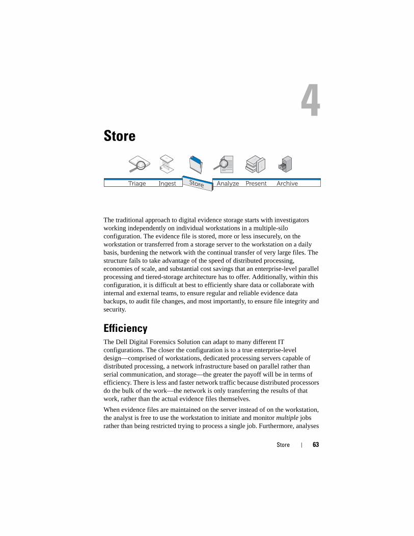
Store
The traditional approach to digital evidence storage starts with investigators working independently on individual workstations in a multiple-silo configuration. The evidence file is stored, more or less insecurely, on the workstation or transferred from a storage server to the workstation on a daily basis, burdening the network with the continual transfer of very large files. The structure fails to take advantage of the speed of distributed processing, economies of scale, and substantial cost savings that an enterprise-level parallel processing and tiered-storage architecture has to offer. Additionally, within this configuration, it is difficult at best to efficiently share data or collaborate with internal and external teams, to ensure regular and reliable evidence data backups, to audit file changes, and most importantly, to ensure file integrity and security.
EfficiencyThe Dell Digital Forensics Solution can adapt to many different IT configurations. The closer the configuration is to a true enterprise-level design—comprised of workstations, dedicated processing servers capable of distributed processing, a network infrastructure based on parallel rather than serial communication, and storage—the greater the payoff will be in terms of efficiency. There is less and faster network traffic because distributed processors do the bulk of the work—the network is only transferring the results of that work, rather than the actual evidence files themselves.
When evidence files are maintained on the server instead of on the workstation, the analyst is free to use the workstation to initiate and monitor multiple jobs rather than being restricted trying to process a single job. Furthermore, analyses
Analyze ArchiveTriage Ingest Present
64 Store
can be completed even more quickly because several analysts and consulting specialists, such as foreign language experts, can work on the same *.E01 file simultaneously from different workstations.
Work can be triaged according to difficulty and assigned to analysts with differing levels of experience; a junior analyst can take charge of the more time-consuming task of pulling graphic files from an *.E01 file, while the more experienced senior analyst can better spend her time doing more complicated review and analysis of those graphic files.
ScalabilityOn the back end, Solution datacenter components are modular; and they are designed with scalability in mind. Because the datacenter is handling the workload, workstations do not have to be loaded with memory or computing power. In fact, very inexpensive, lightweight terminals can be used to access the required evidence files and even the analytical software stored within the datacenter.
SecurityThe escalating trend toward information aggregation makes our data storage systems increasingly vulnerable. At the same time, access to evidence storage should be the most rigorously controlled area of a digital forensics system. Best practice calls for implementation of a three-tiered strategy:
• Strictly regulated physical access that limits access to the hardware on which your evidence data resides
• An administrative control layer that includes the use of group policies
• Computer-based security, such as secure password-creation policies
To this end, when the issue of designing the volume and structure adequate to your needs is addressed (see "Ingest" on page 39), security is an agency’s primary consideration where storage is concerned.
Physical Access Layer
Your digital forensics evidence server files should be housed more securely than any other files in your organization, including Human Resources files.
Store 65
Consider the following suggestions:
• Place the examination servers and data storage inside a dedicated examination laboratory space. In this way, all servers, data warehouses, physical cabling, switches, and routers are physically protected by the same security measures that restrict laboratory access.
• Use entry control protocols, such as fingerprint or retinal scans, or smart card access.
• Route all examination traffic through network switches dedicated to and connected physically to only examination servers and workstations.
Administrative Control Layer and Active Directory
Your solution configuration will run on a Windows operating system, and thus the remainder of this chapter discusses Windows and its Active Directory Group and User security features. Active Directory is built on group security and its related features. A group is a collection of users or computers within a domain. The two basic types of groups are distribution groups (used for E-mail distribution) and security groups. Establishing security groups allows you to create and apply security-related policies, including:
• Access to shared resources and the level of that access
• User rights including password requirements
• Account lockout policies
• Software restriction policies
• Distribution of security patches to notebooks, desktops, and servers
For example, you can create a group containing administrative workstations and a second group containing administrative users. Then, you can use Group Policy Objects (GPOs) to limit access to those workstations and members of the administrative users group. (See "Applying Security Policies Using Group Policy Objects" on page 69 for information on working with group policy objects.)
Computer-Based Security Layer and Active Directory
Active Directory also provides Kerberos, a network authentication security protocol that allows nodes communicating over non-secure networks to prove their identity to one another in a secure manner. See "Active Directory User
66 Store
Accounts" on page 71 for information on working with user accounts, and see also "Active Directory Support for Secure Password Policies" on page 70 for information on password creation.
Additional Information on Security and Digital Forensics
SP 800-41 Rev. 1 Sept. 2009 Guidelines on Firewalls and Firewall Policy
SP 800-46 Rev. 1 Jun. 2009 Guide to Enterprise Telework and Remote Access Security
SP 800-55 Rev. 1 Jul 2008 Performance Measurement Guide for Information Security
Tiered StorageDell’s Digital Forensics Solution uses tiered storage strategies to accommodate rapid data growth while at the same time controlling costs. A mix of SATA and SAS drives of varying capacities and performance levels can be tailored to match data profiles, and this mix can be re-evaluated periodically to maintain optimization over time. Typically, mission-critical data, such as case data for cases currently in the analysis stage, is stored on high-performance, high-cost drives, while less urgent data, such as case files for cases just beginning the appeals process or those cases that are closed, is moved to low-cost, high-capacity drives.
Store 67
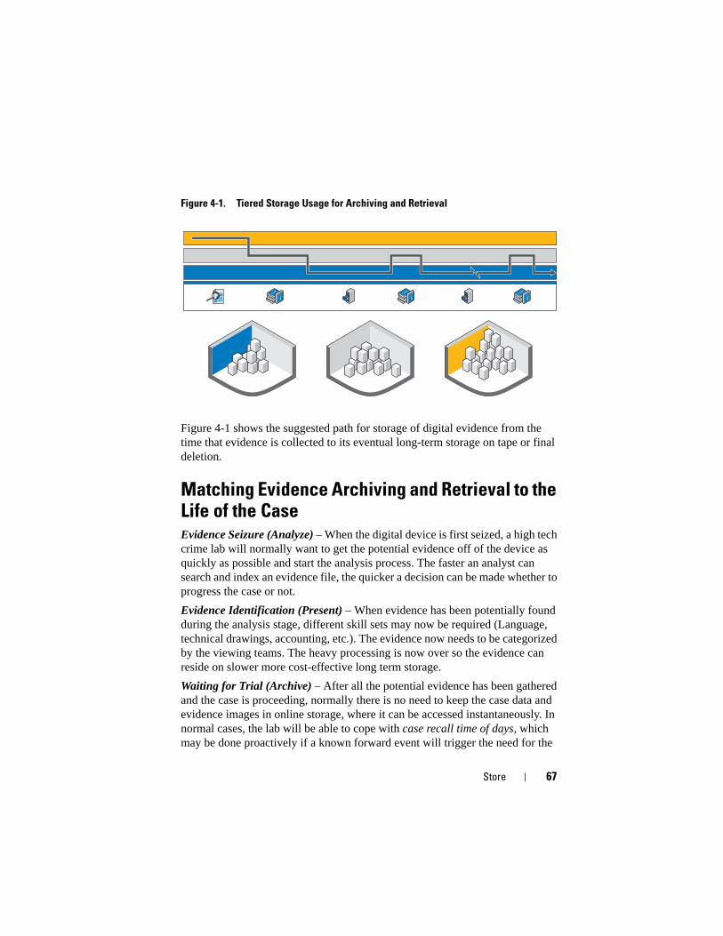
Figure 4-1. Tiered Storage Usage for Archiving and Retrieval
Figure 4-1 shows the suggested path for storage of digital evidence from the time that evidence is collected to its eventual long-term storage on tape or final deletion.
Matching Evidence Archiving and Retrieval to the Life of the CaseEvidence Seizure (Analyze) – When the digital device is first seized, a high tech crime lab will normally want to get the potential evidence off of the device as quickly as possible and start the analysis process. The faster an analyst can search and index an evidence file, the quicker a decision can be made whether to progress the case or not.
Evidence Identification (Present) – When evidence has been potentially found during the analysis stage, different skill sets may now be required (Language, technical drawings, accounting, etc.). The evidence now needs to be categorized by the viewing teams. The heavy processing is now over so the evidence can reside on slower more cost-effective long term storage.
Waiting for Trial (Archive) – After all the potential evidence has been gathered and the case is proceeding, normally there is no need to keep the case data and evidence images in online storage, where it can be accessed instantaneously. In normal cases, the lab will be able to cope with case recall time of days, which may be done proactively if a known forward event will trigger the need for the
68 Store
case data. This approach reduces the cost of storage in the forensics lab because all data does not need to be kept in the lab, no matter what the current relevance, it can be moved seamlessly to slower storage.
Trial (Present) – In the event of the case making it to trial, the forensics lab will want to have quick access to the evidence and case data to respond to any questions during the court case.
Custodial Sentence (Archive) – In the event of a custodial sentence, most countries require the Police or justice department to keep the evidence and case files for a minimum period or the length of the custodial sentence plus a reasonable time for appeal or 99 years. The goal here is to put the data onto a long term inexpensive storage medium that protects the integrity and confidentially of the data.
Appeal (Present) – In the event of appeal, the case data and evidence may need to be recalled for further analysis or scrutiny. This recall needs to happen in a very timely manner, but the data is very rarely required instantaneously.
Delete – In most countries around the globe, public sector bodies are not allowed to hold data indefinitely once the data has reached the legal limit of retention. A simple process needs to be available to delete that data. This process may be required also in the case where a not guilty verdict has been returned, and the data also needs to be deleted.
How to Set Up Storage Security Using the Dell Digital Forensics Solution and Active Directory
Creating and Populating Groups in Active Directory
Groups are established through Active Directory Domain Services (Windows Server 2008).
Creating a New Group (Windows Server 2008)
1 Click Start→ Administrative Tools→ Active Directory Administrative Center.
2 In the navigation pane, right-click the node to which you want to add a new group, click New. Then click Group.
3 Enter the name of the new group.
Store 69
4 Select the appropriate option in Group Scope.
5 Select the Group Type.
6 Select Protect from accidental deletion.
7 Modify the Managed By, Member Of, and Members sections, and then click OK.
Adding Members to A Group (Windows Server 2008)
1 Click Start→ Administrative Tools→ Active Directory Administrative Center.
2 In the navigation pane, click the folder in which the group resides.
3 Right-click the group, and then click Properties.
4 Select Add on the Members tab.
5 Enter the name of the user, computer, or group that you are adding, and then click OK.
Applying Security Policies Using Group Policy Objects
Once you have created a group, you can collectively apply security settings and other attributes to the members of that group by creating and configuring a Group Policy Object (GPO). Doing so makes it easy to maintain security for users and resources as your digital forensics organization changes.
Creating and Editing GPOs
Creating a New GPO (Windows Server 2008)
In Windows Server 2008, GPOs are managed using the Group Policy Management Console (GPMC).
1 To open the GPMC, click Start→ Administrative Tools→ Group Policy Management.
2 Navigate to the forest and domain in which you will create the new object, and then click Group Policy Objects.
3 Click New.
4 Enter the name of the new GPO, and then click OK.
70 Store
Editing a New GPO (Windows Server 2008)
In Windows Server 2008, GPOs are managed using the GPMC.
1 To open the GPMC, click Start→ Administrative Tools→ Group Policy Management.
2 Navigate to the forest and domain in which the GPO resides, and then click Group Policy Objects.
3 Right-click the GPO.
4 Make the necessary changes to the settings and save them.
Active Directory Support for Secure Password Policies
Active Directory supports a variety of authentication policies, including smart cards, strong password, and account lockout settings.
Passwords and other authentication policies are created using GPOs. See "Applying Security Policies Using Group Policy Objects" on page 69 for information on creating and editing a GPO.
Suggested Strong Password Settings
The following values are suggested when configuring password settings:
• Enforce password history - The number of unique passwords that must be used before a password can be reused. Set to 24.
• Maximum password age - Passwords must be changed every x days. Set to 90.
• Minimum password age - The number of days a password must be in effect before it can be changed. Set to 1 or 2.
• Minimum password length - Set to 8 or 12 characters.
• Password must meet complexity requirements - Set to Enabled. The following policies are applied:
– Passwords must be at least 6 characters in length
– Passwords must include characters from at least three of these four categories:
• Uppercase characters
• Lowercase characters
• Numerals (0 through 9)
Store 71
• Symbols
– Passwords must not contain three or more consecutive characters from the account’s name or user’s name
Fine-Grained Password Policies
In Windows Server 2008, Active Directory Domain Services supports Password Setting Objects (PSOs) that apply to particular global security groups or users within a domain. A PSO can specify password length in characters, password complexity, minimum and maximum password age, and other attributes.
Consequently, you can create multiple PSOs that correspond to the organizational structure of your digital forensics facility. For example, you can use PSOs to implement longer passwords that expire monthly for administrative users and shorter passwords that expire every three months for analysts.
Active Directory User Accounts
Establishing User Accounts for Forensics Analysts
1 Open Active Directory Users and Computers:
a Click Start→ Control Panel
b Double-click Administrative Tools, and then double-click Active Directory Users and Computers.
2 In the console tree, right-click the folder in which you want to add a user account.
Where?
Active Directory Users and Computers/domain node/folder
3 Point to New, and then click User.
4 In First name, type the user's first name.
5 In Initials, type the user's initials.
6 In Last name, type the user's last name.
7 Modify Full name to add initials or reverse order of first and last names.
8 In User logon name, type the user logon name, click the UPN suffix in the drop-down list, and then click Next.
72 Store
If the user will use a different name to log on to computers running Windows 95, Windows 98, or Windows NT, then you can change the user logon name as it appears in User logon name (pre-Windows 2000) to the different name.
9 In Password and Confirm password, type the user's password, and then select the appropriate password options.
NOTE: To perform this procedure, you must be a member of the Account Operators
group, Domain Admins group, or the Enterprise Admins group in Active Directory; or
you must have been delegated the appropriate authority. As a security best
practice, consider using Run as to perform this procedure. For more information,
see Default local groups, Default groups, and Using Run as.
Establish an FTK Service Manager Account
NOTE: During the course of FTK installation, you will be asked for the name of the
user account that you plan to use for managing the Distributed Processing feature.
Do not use.
If you are using the distributed processing feature of FTK as one of your digital forensics tools, you must create an FTK Service Manager account in Active Directory to handle automatic updating of passwords. During the FTK installation process, you will be asked to provide the name of the user that will be used to monitor and manage the distributed processing function. This account must be created as a service in Active Directory, and it must have administrator privileges (but should not be the Administrator account) to provide the continual handshake between FTK and the evidence server that the distributed processing feature requires.
1 In Active Directory, open Administrative Tools, and then click Active Directory Users and Computers.
2 In the console tree, double-click the Domain node.
3 In the Details pane, right-click the organizational unit where you want to add the service account. Select New, and then click User.
4 In First name, type FTKServMgr for the service account; leave Last name blank.
5 Modify Full name as desired.

Store 73
6 In User logon name, type FTKServMgr. The service account will log on with the name you entered. From the drop-down list, click the UPN suffix that must be appended to the service account logon name (following the @ symbol). Click Next.
7 In Password and Confirm password, type a password for the service account.
8 Select the appropriate password options, and then click Next.
9 Click Finish to complete creating a service account.
Create a Non-administrative User Account
1 Log on to a computer running Windows Vista with an administrative user account.
2 Open the Start menu. Right-click Computer, and then click Manage.
3 Click the arrow next to Local Users and Groups.
4 Right-click Users, and then click New User.
5 Type the name of the user for whom you are creating an account. For example, if you want to name the user webuser1, then you would type webuser1 in the Username field and also in the Full name field.
6 Type a password that you will remember in the Password and Confirm Password fields.
NOTE: Passwords are case sensitive. The password you type in the Password and Confirm Password fields must match to be able to add the user account.
7 Uncheck the User must change password at next logon check box.
8 Check the Password never expires and User cannot change password check boxes.
9 Click Create, and then click Close.
10 Click File, and then click Exit.
74 Store
Setting Up Security for Individual Case and Evidence Files
1 In Windows Explorer, navigate to the file for which you will establish file permissions. Right-click the file, and then select Properties.
2 Click the Security tab.
3 Uncheck the check box beside Everyone, if necessary.
4 Add only the users who will be requiring access to the file as determined by the policy of your workplace.
a Click Add.
b In the Enter the object names to select field, enter the names of the appropriate users. Then click OK.
c Modify the Permissions for each user as determined by the policy of your workplace.

Store 75

76 Store
Analyze 77
Analyze
There are several different types of analyses the investigator needs to be able to conduct on evidence data, including file signature and hash analysis, and extensive indexing and keyword searches. All of these analyses require considerable processing power as evidence files for a single case can reach sizes approaching the terabyte range, and processing these files can take tens of hours--even days--using datacenter architectures commonly set in place today. Investigators attempting this analysis on a single workstation must take this issue into account when scheduling case processing because the analysis and indexing of a single case may use up the investigator’s hardware assets. Dell’s Digital Forensics Solution provides the significant advantages of distributed processing, and that can change the picture entirely. We’ll take a look at distributed processing shortly, but first let’s examine some of the types of analysis that the digital forensics investigator typically encounters.
Types of Analysis
Hash Analysis
A hash function uses cryptographic algorithms to create a digital fingerprint from data. The hash can be used to compare a hash of the original data to one of the analyzed forensic data, which may be accepted in court as proof that the two groups of data are identical. Hash analysis compares case file hash values with known, stored hash values.
ArchiveTriage Ingest Store Present
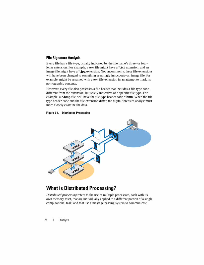
78 Analyze
File Signature Analysis
Every file has a file type, usually indicated by the file name’s three- or four-letter extension. For example, a text file might have a *.txt extension, and an image file might have a *.jpg extension. Not uncommonly, these file extensions will have been changed to something seemingly innocuous--an image file, for example, might be renamed with a text file extension in an attempt to mask its pornographic contents.
However, every file also possesses a file header that includes a file type code different from the extension, but solely indicative of a specific file type. For example, a *.bmp file, will have the file type header code *.bm8. When the file type header code and the file extension differ, the digital forensics analyst must more closely examine the data.
Figure 5-1. Distributed Processing
What is Distributed Processing?Distributed processing refers to the use of multiple processors, each with its own memory asset, that are individually applied to a different portion of a single computational task, and that use a message passing system to communicate
EST
2
4
0
3
5
1
EST
2
4
0
3
5
1
EST
2
4
0
3
5
1
Analyze 79
between one another within the group. Distributed processing is not the same as parallel processing, which refers to the use of multiple processors that share a single memory asset.
Consider the following, which will give you a rough idea of the advantages of the Dell Solution using a distributed processing installation, using distributed processing, completing an analysis of five 200 GB files may take only 3.5 hours while processing a single 200 GB file on a standalone workstation might take roughly 7-8 hours to accomplish.
Moving evidence data processing from the analyst’s workstation to the server isn’t the end; the Dell Solution also offers the option of running analytical software itself, such as FTK and EnCase on the server, allowing the workstation to become an integrated interface that is able to run multiple instances of different forensics software packages under concurrently-viewed operating systems with no client performance degradation.
Using Distributed Processing in FTK 3.1Distributed Processing allows you to apply the additional resources of up to three additional computers at a time to the processing of your cases. Once you have installed and configured the Distributed Processing Engine, you can reduce your case processing time exponentially.
NOTE: As a rule of thumb, using Distributed Processing does not reduce
processing times unless the number of objects to be processed exceeds 1,000 times
the number of cores that exist within the system. For example, on a system with
eight cores, the additional distributed processing engine machines may not lower
processing time unless the evidence contains more than 8,000 items.
NOTE: For information on installing and configuring the Distributed Processing
module as part of your Solution, refer to the appropriate section of the FTK User
Guide.
1 Make sure the case folder is shared before trying to add and process evidence. If you are following Dell’s recommended filenaming conventions, the case folder should be located on your workspace drive, W:/. If you are unsure where your case folder is located, contact your systems administrator.
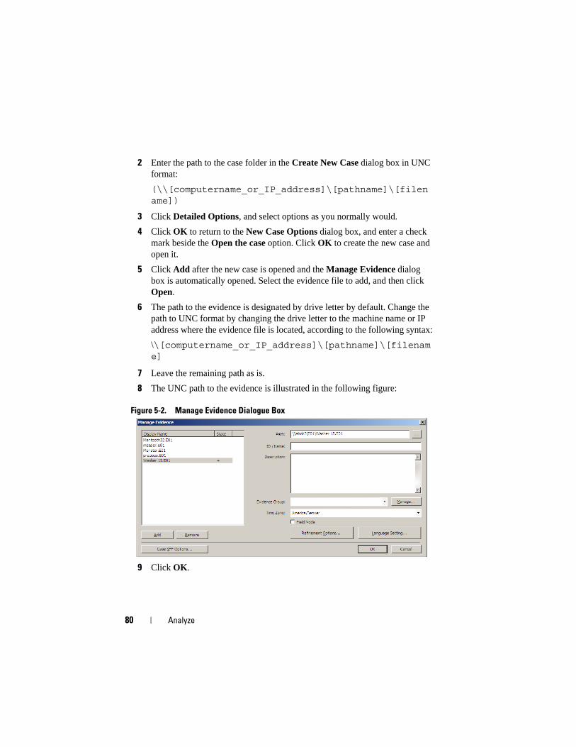
80 Analyze
2 Enter the path to the case folder in the Create New Case dialog box in UNC format:
(\\[computername_or_IP_address]\[pathname]\[filename])
3 Click Detailed Options, and select options as you normally would.
4 Click OK to return to the New Case Options dialog box, and enter a check mark beside the Open the case option. Click OK to create the new case and open it.
5 Click Add after the new case is opened and the Manage Evidence dialog box is automatically opened. Select the evidence file to add, and then click Open.
6 The path to the evidence is designated by drive letter by default. Change the path to UNC format by changing the drive letter to the machine name or IP address where the evidence file is located, according to the following syntax:
\\[computername_or_IP_address]\[pathname]\[filename]
7 Leave the remaining path as is.
8 The UNC path to the evidence is illustrated in the following figure:
Figure 5-2. Manage Evidence Dialogue Box
9 Click OK.
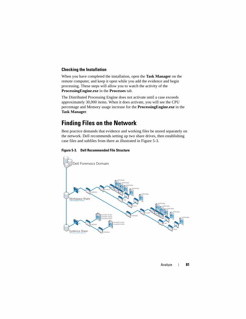
Analyze 81
Checking the Installation
When you have completed the installation, open the Task Manager on the remote computer, and keep it open while you add the evidence and begin processing. These steps will allow you to watch the activity of the ProcessingEngine.exe in the Processes tab.
The Distributed Processing Engine does not activate until a case exceeds approximately 30,000 items. When it does activate, you will see the CPU percentage and Memory usage increase for the ProcessingEngine.exe in the Task Manager.
Finding Files on the NetworkBest practice demands that evidence and working files be stored separately on the network. Dell recommends setting up two share drives, then establishing case files and subfiles from there as illustrated in Figure 5-3.
Figure 5-3. Dell Recommended File Structure
Evidence Share\\Fileserver\Evidence
CASE0001
CASE0002
Case0001-01.E01
Case0001-02.E01
Case0001-03.E01
Case0002-01.E01
Case0002-02.E01
Dell Forensics Domain
Workspace Share\\Workspace\Share
CASE0001
CASE0002
Encase6
FTK3
FTK1.8
Encase6
FTK3
FTK1.8
V:\
M:\
Export
Temp
Index
Export
Temp
Index
XXXXX.&&&
XXXXX.&&&
XXXXX.&&&
XXXXX.&&&
XXXXX.&&&
XXXXX.&&&
XXXXX.&&&
XXXXX.&&&
XXXXX.&&&
XXXXX.&&&
82 Analyze
Analysis Using FTK
Open an Existing Case
Using the File Menu
1 From within FTK, select File, and then select Open Case.
2 Highlight the case you want to open and click it to launch the case.
NOTE: All case files are named case.ftk. The case.ftk file for each case is stored in
the applicable case folder.
From the Command Line
At the command line type:
path_to_ftk_program_file\ftk.exe /OpenCase target_case_directory
Processing Case Evidence
FTK processes evidence as a case is created or as evidence is later added to the case. For instructions on creating a new case, see "Create a Case" on page 59 or refer to the FTK User’s Guide. For instructions on adding evidence to an existing case, see "Add Evidence to a Case" on page 60 or refer to the FTK User’s Guide. See "Related Documentation and Resources" on page 16 for more information.
Analysis Using EnCase
Open an Existing Case
1 From the file menu, select File→ Open.
2 Browse to the case and click Open.
Analyze 83
Create an Analysis Job
1 Click the Analysis Jobs tab in the main Source Processor dialog.
2 Click New. The Create Analysis Job/Job Name dialog displays.
The default job name is Job__[yyyy_mm_dd__hh_mm_ss], for example: Job___2009_06_24__03_42_42_PM.
A job name cannot contain spaces at the beginning or end of the name, or any of the following characters: \ / : * ? " < > |
3 Enter a job name and click Next. The Create Analysis Job/Module Selection dialog displays.
This dialog shows module folders in the left pane and single modules within those folders in the right pane.
If a module is included in an analysis job, but there is no data for that module when that job is run against a collection, that module is ignored. This feature allows you to create generic analyses jobs for a variety of collected data sets.
4 Enter a check the module's check box.
You may select more than one module.
Analyses modules do not have user configurable settings.
To select all the modules in a group, enter a check beside that group's folder name in the left pane.
5 Click Finish.
NOTE: Analyses jobs may list available modules not listed in collection jobs. These
modules are identified as legacy modules so you can analyze data that was
collected in previous versions of Source Processor using modules that no longer
exist.
Run an Analysis Job
1 From the Collected Data tab, select the evidence that you want to analyze by first selecting the job name in the left pane. Then, select the actual evidence files in the table on the right.
2 Click Run Analysis. The Select Analysis to Run dialog opens.

84 Analyze
3 Select the analysis job, and then click Run. Source Processor runs the analysis on the selected evidence. When the analysis is complete, the data browser displays.
Performing a Signature Analysis
1 Click Search.
2 Check the Verify file signatures box in the Additional Options area in the lower right, and then click Start. The signature analysis routine runs in the background. On completion, a search complete dialog displays. The dialog presents search status, times, and file data.
You can view these same data in the console.
Viewing Signature Analysis Results
1 Click Set-Include in the Tree pane to display all files in the case.
At this level, Set Include selects everything in the evidence file.
2 Organize the columns in the Table pane so that the Name, File Ext, and Signature columns are next to each other.
3 Sort columns with Signature at the first level, File Ext at the second level and Name at the third level.
Scroll up or down to see all the signatures.
4 Click Set-Include in the Entries selection in the Tree pane.
A list of case files with their associated file signatures and other data displays in the Table pane.
5 Sort the data as desired.
Present 85
Present
Reporting the results of your analysis is an integral part of the Dell Digital forensics Solution, and is handled primarily through the forensics software you are using as part of the Solution.
How to Create Reports Using the Dell Digital Forensics Solution
Create and Export Reports Using EnCase 6
1 Select the items to report on, whether they are files, bookmarks, search hits, or other data.
2 Select the type of report you want using the tabs in the Tree pane.
3 From the Table tab in the Table pane, enable the items you want to show in the report.
4 From the Table tab, switch to the Report tab.
5 Modify the report as needed.
6 Export the report to a format viewable outside EnCase.
a Right-click in the report and click Export from the drop-down menu. The Export Report dialog opens.
b Click the appropriate radio button to select the output format you want to use (TEXT, RTF, or HTML).
c Enter or navigate to the output path.
ArchiveTriage Ingest Store Analyze
86 Present
d If desired, select Burn to Disc to enable the Destination Folder box, then right-click Archive Files to create a new folder and save an .iso file to disc.
e Click OK
Reports Using FTK
1 Click File→ Report to launch the Report Wizard.
2 Enter the basic case information requested by the wizard.
3 Select the properties for bookmarks.
4 Determine whether and how you want to display case graphics in your report.
5 Determine whether or not you want to include a section in your report that lists the file paths and file properties of files in selected categories.
6 Add the Registry Viewer sections if desired.
View the report outside of FTK
1 Browse to the report file.
2 Click the report file, then:
• Click index.htm to open an HTML document in a web browser.
• Click [report].pdf to open the report in a PDF viewer.
Archive 87
Archive
No digital forensics solution is complete without a scalable, secure, and comprehensive archive and retrieval component. Your Dell Digital Forensics Solution offers that and more. In the Dell Solution framework, we have tried to create a simple interface that works with all forensics applications to control the life cycle of the evidence and case files. Due to the fact that it is difficult to predict when data might be needed in the future or how long an investigation may last, we have created a flexible solution that requires the individual forensics analyst to determine the files he will recall and archive. This solution uses a tiered approach to storage tailored to your needs--a mix of SATA and SAS hardware--and user-driven archiving using NTP’s On-Demand Archiving software.
Dell’s Solution consists of modular components that provide a scalable environment that can be expanded to meet growing demands for processing and storage requirements. The Solution’s formalized backup, recovery, and archiving (BURA) infrastructure helps optimize cooperation between agencies and forces, and across borders. It frees up administrative burdens by automating much of the task of backing up data, provides consistency between interagency labs, and minimizes risks to the digital chain of custody.
Triage Ingest Store Analyze Present
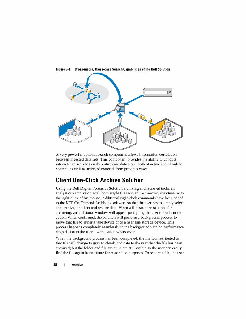
88 Archive
Figure 7-1. Cross-media, Cross-case Search Capabilities of the Dell Solution
A very powerful optional search component allows information correlation between ingested data sets. This component provides the ability to conduct internet-like searches on the entire case data store, both of active and of online content, as well as archived material from previous cases.
Client One-Click Archive SolutionUsing the Dell Digital Forensics Solution archiving and retrieval tools, an analyst can archive or recall both single files and entire directory structures with the right-click of his mouse. Additional right-click commands have been added to the NTP On-Demand Archiving software so that the user has to simply select and archive, or select and restore data. When a file has been selected for archiving, an additional window will appear prompting the user to confirm the action. When confirmed, the solution will perform a background process to move that file to either a tape device or to a near line storage device. This process happens completely seamlessly in the background with no performance degradation to the user’s workstation whatsoever.
When the background process has been completed, the file icon attributed to that file will change to grey to clearly indicate to the user that the file has been archived; but the folder and file structure are still visible so the user can easily find the file again in the future for restoration purposes. To restore a file, the user
Archive 89
merely needs to navigate through the original folder structure, locate the folder or file she wants to restore, right-click the file or folder, and then select the restore option.
Dell recommends that all evidence and case files be located on a central scalable NAS device that allows for a central expandable point of storage, allowing for easy collaboration between analysts. This recommendation also allows a single point of audit for chain-of-custody purposes. When a file has been selected for archive, it is moved into the next available system processing window from the primary storage to a secondary option (tape or near line).
Archive and recall times will vary greatly depending on the current traffic to and from the centralized NAS storage, the current files being archived, and the type of media that comprises the secondary storage option. For example, near line SATA will deliver much quicker completion rates than tape. All files can be encrypted onto tape for additional security when they reach the long-term archive phase of the Solution, which may require additional licensing.
Dell Backup Recommendations
Backup of Evidence and Case files
A forensics lab has three core file types:
• Image files – These are the forensically-sound images of the suspect device. Once ingested, they never change and only need to be backed up once (possible extensions: E01, DD, etc.). Evidence files tend to be found low in quantity but very large in size.
• Case files – These are the data files and indexes that are the result of analyses; they may need to be exported out of the forensics application. The files change frequently if the case is currently live, and they can contain multiple extension types, requiring them to be backed up on a daily basis. Case files tend to be numerous in quantity but usually very small in size.
• Database – This file type is used only in FTK 3 (at the moment), but it holds all of the links between the case files and the evidence files, as well as all of the investigation bookmarks and notes. Database file types must be backed up daily.
Figure 7-2 shows the suggested best practice for backing up a digital forensics lab. Due to the fact that many forensics labs have 50 TB plus of storage, it may not be possible to complete a full backup in a standard weekend backup window.
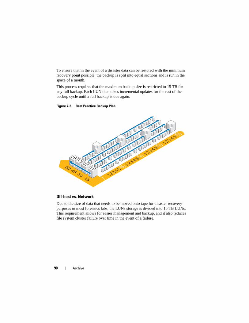
90 Archive
To ensure that in the event of a disaster data can be restored with the minimum recovery point possible, the backup is split into equal sections and is run in the space of a month.
This process requires that the maximum backup size is restricted to 15 TB for any full backup. Each LUN then takes incremental updates for the rest of the backup cycle until a full backup is due again.
Figure 7-2. Best Practice Backup Plan
Off-host vs. Network
Due to the size of data that needs to be moved onto tape for disaster recovery purposes in most forensics labs, the LUNs storage is divided into 15 TB LUNs. This requirement allows for easier management and backup, and it also reduces file system cluster failure over time in the event of a failure.

Archive 91
Two types of backup can be performed, either over the network or as an off-host backup.
• In an over-the-network configuration, all backup data is transmitted over the network to the backup server using a backup agent that is resident on the server.
• In an off-host backup solution, some of the servers with the larger file stores do not back up their data over the network. Instead the storage array takes a snapshot of the LUN and then mounts this copy directly to the backup server. This process increases overall backup speed as no backup files are transmitted over the normal network to cause additional network contention issues.
In many forensics labs today, backups are conducted over 10 GB networks.
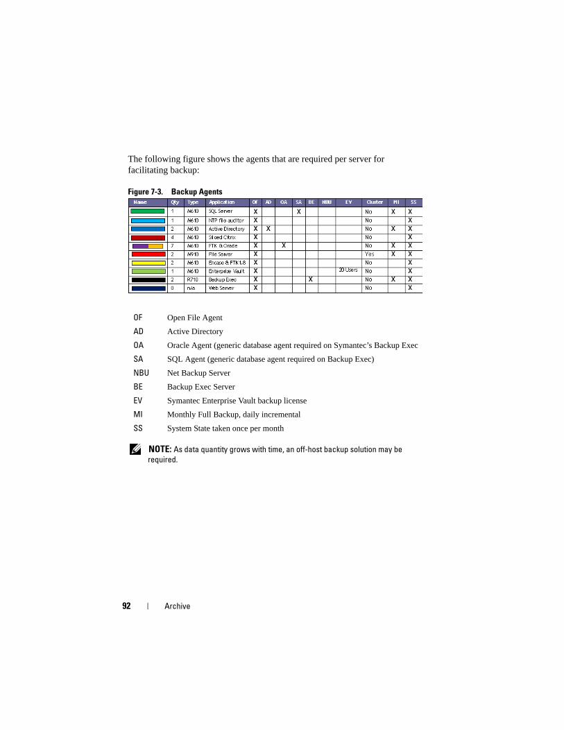
92 Archive
The following figure shows the agents that are required per server for facilitating backup:
Figure 7-3. Backup Agents
NOTE: As data quantity grows with time, an off-host backup solution may be
required.
OF Open File Agent
AD Active Directory
OA Oracle Agent (generic database agent required on Symantec’s Backup Exec
SA SQL Agent (generic database agent required on Backup Exec)
NBU Net Backup Server
BE Backup Exec Server
EV Symantec Enterprise Vault backup license
MI Monthly Full Backup, daily incremental
SS System State taken once per month
Archive 93
How to Archive Using the Dell Digital Forensics Solution
On-Demand Archiving
NTP Software ODDM and NTP Software Right-Click Data Movement (RCDM) work in conjunction with Enterprise Vault to mitigate the need for scans of the entire file system, as in the case of conventional archiving, by implementing on-demand archiving. Storage costs are reduced and the quality of archiving is improved.
Depending on the stage of the data life cycle, as described in "Matching Evidence Archiving and Retrieval to the Life of the Case" on page 67, the analyst may choose to archive data in longer-term storage, or retain the data for immediate access and processing.
In addition, NTP Software ODDM can be used to automatically archive data that must be stored for legal purposes.
Requirements
NTP Software ODDM requires Microsoft IIS, Microsoft .NET Framework, SQL, and Enterprise Vault. NTP Software ODDM and Enterprise Vault must be installed on the same server. Larger installations can maintain the SQL database on a dedicated server.
Installation
For detailed installation instructions for NTP Software ODDM and NTP Software RCDM, see the Dell Digital Forensics Installation and Configuration Guide. See "Related Documentation and Resources" on page 16 for more information.
Archiving Using NTP Software ODDM
User-Driven Archiving
1 When the analyst stores data files, NTP Software QFS will alert the user that the files may need to be archived.
94 Archive
2 The analyst selects the files to be archived using the NTP Software Storage Investigator, and then clicks Archive. However, if the NTP RCDM add-on is installed, he right-clicks the files.
When the files are selected, the NTP Software Storage Investigator notifies NTP Software ODDM, which in turn activates Enterprise Vault.
The archive request is added to the archiving queue.
Troubleshooting 95
Troubleshooting
General Troubleshooting Tips• Make sure all clients and servers can see each other—that they are able to
ping one another by both the NetBIOS name as well as by the IP address.
• Make sure firewalls allow traffic.
• Reboot servers and clients to make sure that all installation and configuration changes have been recognized by the systems.
Forensics Software-Specific Issues
EnCase: EnCase launches in Acquisition Mode
This issue indicates that EnCase has no license.
1 Within EnCase select Tools→ Options and make sure the User Key Path, Server Key Path, and Server Address are filled out (these fields should point to the locations of the license keys).
2 Check the firewall on the client and EnCase license server to make sure port 4445 is open.
3 Make sure the client can ping the EnCase license server.
StoreIngest Store Analyze ArchiveTriage Present
96 Troubleshooting
FTK Lab: Browser launched by client cannot display User Interface
1 Make sure the client has MS Silverlight installed.
2 Make sure Oracle services have started on the server hosting the Oracle database.
FTK 1.8: 5000 object limit\trial version message
If you receive this message, FTK has no license. Ensure that the network license server is working and has the FTK 1.8 licenses in place:
1 Open a browser window on the server hosting the network license service, and enter http://localhost:5555 into the address bar.
2 Observe whether or not the licenses are in place. If they are not, you must install the licenses.
FTK 1.8: Cannot Access Temp File error appears on launch
Allow the user launching the application (or their Citrix session) to have access to the server hard drive OR run the application as an administrator.
Citrix Issues
Citrix: Applications won’t launch
1 Make sure all the services (particularly MFCOM and IMA) have started on the servers hosting XenApp.
2 Make sure the client can see and ping the XenApp servers.
3 Check the firewall on clients and XenApp servers to make sure XenApp ports are open.
4 Check the Citrix license server to make sure the network licensing service has a license it can issue. The Citrix Licensing Server is typically installed on one of the Citrix XenApp servers, accessible via Start→ Programs→ Citrix→ Management Consoles→ Citrix Licensing.
5 Open the Citrix Management Console (Start→ Programs→ Citrix→ Management Consoles→ Citrix Delivery services console). Then run a discovery to ensure that all the XenApp servers are present in the farm.
6 Ensure that the application has been published to a valid XenApp server (that is included in the farm).
Troubleshooting 97
7 Look in the Citrix Delivery Services Console to make sure that the user launching the application is in a Group allowed to launch the application.
8 For streamed applications, make sure that User Account Control (UAC) is turned off on the server.
Frozen or Crashed Citrix Sessions
When users do not log off from their Citrix sessions properly, the orphaned sessions begin to slow and may eventually cause the server to freeze or crash. Therefore, it is extremely important that users follow best practices to formally and properly log off each session (Start→ Logoff→ Ok) and not to simply click the boxed x in the upper right hand corner of the session window.
However, you may still encounter this issue, and here are two ways to resolve it:
1 Manually log off the user.
a Open a session as the Citrix Administrator.
b Review the list of open sessions and manually close each session.
2 Reboot the server.

98 Troubleshooting
Index 99
Index
A
Analyze, 9-10, 67, 77EnCase, 82types of analysis, 77
Archive, 9, 11, 67-68, 93and recall times, 89client one-click, 88using NTP Software ODDM, 93
B
Backup, 89agents, 92best practices, 89network, 91off-host, 91off-host vs. network, 90
C
Collectorcleaning, 23deploying, 34Register, 21
Collector Profileconfiguring, 23
D
Distributed Processingcompared to parallel
processing, 78definition, 78using FTK 3.1, 79
E
EnCaseanalysis, 82create and export reports, 85datacenter-enabled, 39how to create an analysis job, 83how to open an existing case, 82how to perform a signature
analysis, 84how to run an analysis job, 83troubleshooting, 95
F
File Signature Analysis, 78
FTK1.8 and 3.0 datacenter-enabled,
ingest, 561.8, datacenter-enabled, 423, datacenter-enabled, 433, Lab Edition, 463.0 Lab Edition, ingest, 59
Index 100
viewing reports, 86
H
Hash Analysis, 77
I
Ingest, 9, 39, 51definition, 10using EnCase, 53using FTK, 56using SPEKTOR, 51
L
live acquisitionvs. standard acquisition, 20
N
Network Configuration, 48drive letter mapping, 49file structure, 50IP address structure, 48NIC teaming naming
conventions, 49server naming conventions, 48
NTP Software ODDM, 93
NTP Software RCDM, 93
O
On-Demand Archiving, 93installation, 93ODDM, 93RCDM, 93requirements, 93
P
Present, 9, 11, 67-68, 85
R
Ruggedized laptophow to turn on, 20
S
Solution Components, 12in the datacenter, 13in the field, 12
SPEKTORclean a collector or store disk, 23configure a collector for
acquisition, 24deploying against targets, 33ingest, 51optional imager module, 10register a collector or store disk, 21review reports, 36
standard acquisitionvs. live acquisition, 20
Store, 9-10, 63

Index 101
Store Diskcleaning, 23register, 21
T
Tableau Write-Blocker, 54connecting to IDE HD, 55connecting to SATA HD, 55
Tiered Storage, 66
Triage, 9, 17, 87definition, 17how to perform, 20reviewing collected files, 36
Troubleshooting, 95Citrix, 96EnCase, 95forensics software, 95FTK 1.8, 96FTK Lab, 96general tips, 95

102 Index