Embed Size (px)
Citation preview
w w w . d e l l . c o m | s u p p o r t . d e l l . c o m
Dell™ OpenManage™ Baseboard
Management Controller Utilities
User’s Guide

Notes and Notices NOTE: A NOTE indicates important information that helps you make better use of
your computer.
NOTICE: A NOTICE indicates either potential damage to hardware or loss of data and tells you how to avoid the problem.
____________________
Information in this document is subject to change without notice.© 2007 Dell Inc. All rights reserved.
Reproduction in any manner whatsoever without the written permission of Dell Inc. is strictly forbidden.
Trademarks used in this text: Dell, the DELL logo, OpenManage, PowerVault, PowerConnect, and PowerEdge are trademarks of Dell Inc.; Microsoft, Windows, Windows Server and M-DOS are either trademarks or registered trademarks of Microsoft Corporation in the United States and/or other countries; Red Hat and Red Hat Enterprise Linux are registered trademarks of Red Hat Corporation; SUSE is a registered trademark of Novell, Inc.; Intel is a registered trademark of Intel Corporation.
Other trademarks and trade names may be used in this document to refer to either the entities claiming the marks and names or their products. Dell Inc. disclaims any proprietary interest in trademarks and trade names other than its own.
August 2007
Contents 3
Contents
1 Introduction . . . . . . . . . . . . . . . . . . . . . . . . 9
What’s New in BMC Management Utility 3.0 . . . 10
Supported Systems . . . . . . . . . . . . . . . . . . . 10
BMC Configuration and Management Tasks . . . . . . 12
Configuring the BMC . . . . . . . . . . . . . . . . 12
Managing the System Using BMC . . . . . . . . . 12
BMC Action on Event . . . . . . . . . . . . . . . 14
Basic BMC Alerting Over a LAN . . . . . . . . . . 14
IPMI Shell Over a LAN . . . . . . . . . . . . . . . 15
IPMI Shell Over the Serial Cable . . . . . . . . . . 17
SOL Proxy Over a LAN . . . . . . . . . . . . . . . 19
BMC Configuration and Management Tools . . . . . . 21
Using the Remote Access Configuration Utility . . . . . . . . . . . . . . . . . . . . . . . . 21
Using Deployment Toolkit . . . . . . . . . . . . . 21
Using the BMC Management Utility . . . . . . . . 21
Using Server Administrator . . . . . . . . . . . . 22
Other Dell Documents You May Need . . . . . . . . . 22
Obtaining Technical Assistance . . . . . . . . . . . . 23
4 Contents
2 Configuring Your Managed System . . . . . 25
BIOS Configuration . . . . . . . . . . . . . . . . . . . 25
Configuring System BIOS in Dell PowerEdge™ x8xx/x9xx Systems . . . . . . . 26
Configuring System BIOS in Dell PowerEdge™ x9xx and xx0x Systems . . . . . 27
Using BIOS Console Redirection With SOL Proxy . . . . . . . . . . . . . . . . . . . . . . 29
Baseboard Management Controller Configuration . . . 29
Entering the Remote Access Configuration Utility . . . . . . . . . . . . . . . . . . . . . . . . 30
Remote Access Configuration Utility Options . . . . . . . . . . . . . . . . . . . . . . . 30
Configuring Your BMC Using the Deployment Toolkit Utility . . . . . . . . . . . . . . . . 36
Installation and Setup for Microsoft Windows PE Operating Systems . . . . 37
Creating a Bootable Windows PE 2005 ISO Image . . . . . . . . . . . . 38
Creating a Bootable Windows PE 2.0 ISO Image . . . . . . . . . . . . 40
Installation and Setup for Linux Operating Systems . . . . . . . . . . . . . . 41
Basic configuration . . . . . . . . . . . . . . . . 42
Configuring Your BMC Using Server Administrator . . . . . . . . . . . . . . . . . . 45
Using Dell Remote Access Controller 5 . . . . . . 47
3 Using the BMC Management Utility . . . . 49
Installing the BMC Management Utility . . . . . . . . 50
Installation Prerequisites . . . . . . . . . . . . . . 50
Supported Operating Systems . . . . . . . . . . . 51
Contents 5
Installation Procedures . . . . . . . . . . . . . . . . . 52
Installing on Systems Running Supported Windows Operating Systems . . . . . . . . . . . 52
Uninstalling on Systems Running Supported Windows Operating Systems . . . . . . . . . . . 53
Installing on Systems Running Supported Linux Enterprise Operating Systems . . . . . . . . 54
Uninstalling on Systems Running Supported Linux Enterprise Operating Systems . . . . . . . . 55
IPMI Shell . . . . . . . . . . . . . . . . . . . . . . . . 55
Using IPMI Shell . . . . . . . . . . . . . . . . . . 57
IPMI Shell Command Syntax . . . . . . . . . . . . 57
IPMI Shell Global Options . . . . . . . . . . . . . 58
IPMI Shell Commands . . . . . . . . . . . . . . . 64
SOL Proxy . . . . . . . . . . . . . . . . . . . . . . . . 76
Using SOL Proxy . . . . . . . . . . . . . . . . . . 78
Using SOL proxy in command mode . . . . . . . . 88
Configuring the SOL Proxy Configuration File . . . . . 90
IPMItool . . . . . . . . . . . . . . . . . . . . . . . . . 93
IPMItool Command for Dynamic Entry on the DNS Server When DRAC is Not Present . . . . . . 96
4 Known Issues and Frequently Asked Questions . . . . . . . . . 103
Known Issues . . . . . . . . . . . . . . . . . . . . . . 103
General Issues . . . . . . . . . . . . . . . . . . . 103
SOL Proxy Issues . . . . . . . . . . . . . . . . . . 103
IPMI Shell Issues . . . . . . . . . . . . . . . . . 104
Frequently Asked Questions . . . . . . . . . . . . . . 104

6 Contents
A BMC Management Utility Error Codes . . . . . . . . . . . . . . . . . . . . . . 107
B Terminal Mode Commands . . . . . . . . . . 111
Configuring Terminal Mode . . . . . . . . . . . . 111
Using Terminal Mode . . . . . . . . . . . . . . . . 112
Security Information . . . . . . . . . . . . . . . . . . . 112
Syntax . . . . . . . . . . . . . . . . . . . . . . . . . . 113
Command Length . . . . . . . . . . . . . . . . . . 113
Character Support . . . . . . . . . . . . . . . . . 113
Hex-ASCII Command Format . . . . . . . . . . . . . . 114
Text Command Format . . . . . . . . . . . . . . . . . . 114
Examples . . . . . . . . . . . . . . . . . . . . . . 115
C Escape Key Sequences . . . . . . . . . . . . . 123
Contents 7
D Serial Port Console Redirection . . . . . . 125
Serial Communication . . . . . . . . . . . . . . . . . 125
Console Redirection Via COM1 . . . . . . . . . . 125
Console Redirection Via COM2 . . . . . . . . . . 125
Serial Terminal Communication to BMC or DRAC . . . . . . . . . . . . . . . . . . . 126
SPCR Table . . . . . . . . . . . . . . . . . . . . . . . 126
Serial Console redirection With SOL Proxy . . . . . . 127
Configuring Linux for Serial Redirection During Boot . . . . . . . . . . . . . . . . . . . . . 127
Enabling Login to the Console After Boot . . . . . 129
Glossary . . . . . . . . . . . . . . . . . . . . . . . . . . . . 133
Index . . . . . . . . . . . . . . . . . . . . . . . . . . . . . . 153

8 Contents
Introduction 9
Introduction The Dell™ systems’ baseboard management controller (BMC) monitors the
system for critical events by communicating with various sensors on the
system board and sends alerts and logs events when certain parameters exceed
their preset thresholds. The BMC supports the industry-standard Intelligent
Platform Management Interface (IPMI) specification, enabling you to
configure, monitor, and recover systems remotely. The BMC provides the
following features:
• Access through the system’s serial port and integrated NIC
• Fault logging and SNMP alerting
• Access to the system event log (SEL) and sensor status
• Control of system functions including power on and power off
• Support that is independent of the system’s power or operating state
• Text console redirection for system setup, text-based utilities, and
operating system consoles
• Access to Linux Enterprise server serial console interfaces by using Serial
over LAN (SOL).
Dell provides several distinct utilities and programs for accessing the BMC to
perform management activities. The following BMC interfaces allow you to
configure and manage your system through the BMC:
• The BMC Management Utility allows remote, out-of-band LAN and/or
serial port power control, event log access, and console redirection.
• The Remote Access Configuration Utility enables configuring BMC in a
pre-operating system environment.
• The Dell OpenManage™ Deployment Toolkit SYSCFG utility provides a
powerful command line configuration tool.
• Dell OpenManage Server Administrator allows remote, in-band access to
event logs, power control, and sensor status information and provides the
ability to configure the BMC.
• Command Line Interface (CLI) tools provide a command line tool for sensor
status information, System Event Log (SEL) access, and power control.
10 Introduction
Additionally, the BMC can be accessed by standard, off-the-shelf terminal or
terminal emulator utilities that allow access to sensor status information and
power control.
What’s New in BMC Management Utility 3.0
The BMC Management Utility (BMU) 3.0 has the following new features:
• IPMItool command line interface available for Dell x8xx, x9xx, and xx0x
systems running supported Microsoft®
Windows®
and Linux systems.
• New commands to manage the LCD display in x9xx and xx0x systems.
• New commands to monitor your system’s power.
• Added support for Windows Server®
2008 (includes Standard, Enterprise,
and Web editions.)
NOTE: Microsoft Windows Server 2008 is scheduled to be available in the first half of 2008. For latest information, see http://www.microsoft.com/windowsserver2008/default.mspx.
Supported SystemsThe BMC management features documented in this guide are supported on
the following Dell systems:
• 800
• 830
• 840
• 850
• 860
• SC1425
• SC1435
• 1800
• 1850
• 1855
• 1900
• 1950

Introduction 11
• 1955
• 2800
• 2850
• 2900
• 2950
• 2970
• 6800
• 6850
• 6950
• T105
• R900
• Dell PowerVault™ NX1950
• PowerVault 100
• PowerVault 500
• PowerVault 600
NOTE: All references in this document to x9xx systems also apply to the PowerVault NX1950, PowerVault 500, and PowerVault 600 systems. All references to the PowerEdge 840 system also apply to the PowerVault 100 system.
12 Introduction
BMC Configuration and Management TasksThe following sections document the basic tasks needed to set up and
configure the BMC on a managed system in preparation for using the BMC
Management Utility. These basic tasks are:
• Configuring the BMC
• Managing the BMC
Configuring the BMC
To configure the BMC on a managed system in a pre-boot environment, you
can use:
• Dell Deployment Toolkit (DTK)
• Remote Access Configuration Utility
• Dell Remote Access Controller (DRAC) 5 graphical user interface (GUI)
• command line interface (CLI)
from a management station depending on the scope of your required
configuration tasks. Alternately, you can configure the BMC on a managed
system with a running operating system using the Server Administrator home
page GUI or CLI. See "Baseboard Management Controller Configuration" for
more information.
Managing the System Using BMC
To manage the BMC in a pre-boot environment, or to access the BMC of a
system, you can use the BMC Management Utility. See "Using the BMC
Management Utility." To configure the BMC on a system with a running
operating system or to perform everyday BMC management tasks, you can
use the GUI on the Server Administrator home page. See the Server
Administrator User’s Guide for more information about using Server
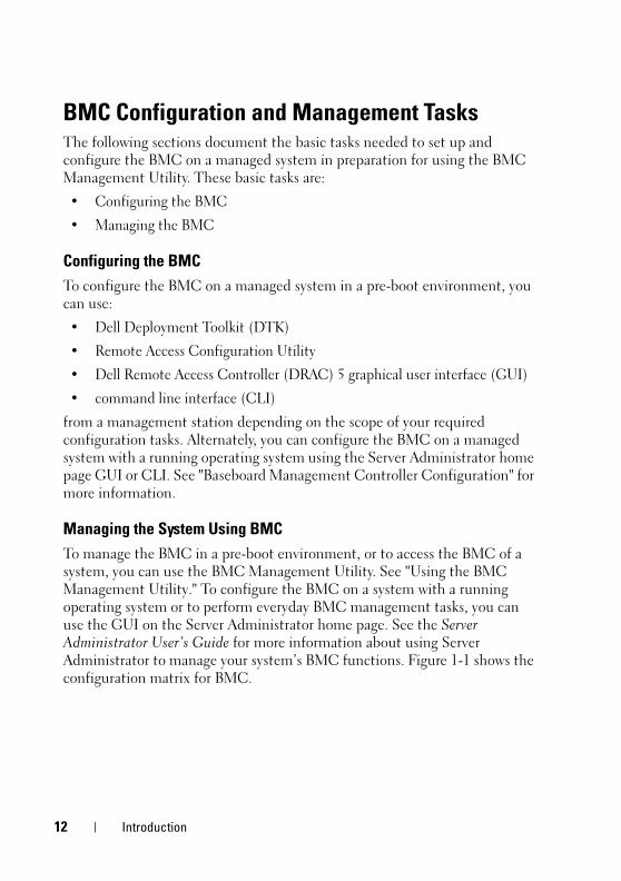
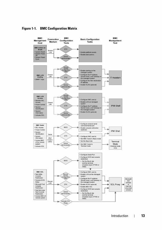
Administrator to manage your system’s BMC functions. Figure 1-1 shows the
configuration matrix for BMC.
Introduction 13
Figure 1-1. BMC Configuration Matrix
14 Introduction
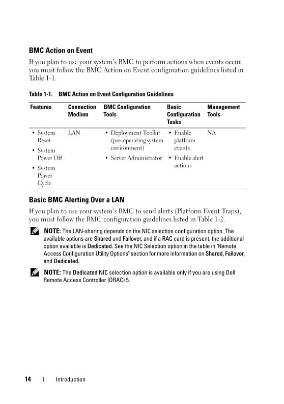
BMC Action on Event
If you plan to use your system’s BMC to perform actions when events occur,
you must follow the BMC Action on Event configuration guidelines listed in
Table 1-1.
Basic BMC Alerting Over a LAN
If you plan to use your system’s BMC to send alerts (Platform Event Traps),
you must follow the BMC configuration guidelines listed in Table 1-2.
NOTE: The LAN-sharing depends on the NIC selection configuration option. The available options are Shared and Failover, and if a RAC card is present, the additional option available is Dedicated. See the NIC Selection option in the table in "Remote Access Configuration Utility Options" section for more information on Shared, Failover, and Dedicated.
NOTE: The Dedicated NIC selection option is available only if you are using Dell Remote Access Controller (DRAC) 5.
Table 1-1. BMC Action on Event Configuration Guidelines
Features Connection Medium
BMC Configuration Tools
Basic Configuration Tasks
Management Tools
• System
Reset
• System
Power Off
• System
Power
Cycle
LAN • Deployment Toolkit
(pre-operating system
environment)
• Server Administrator
• Enable
platform
events
• Enable alert
actions
NA
Introduction 15
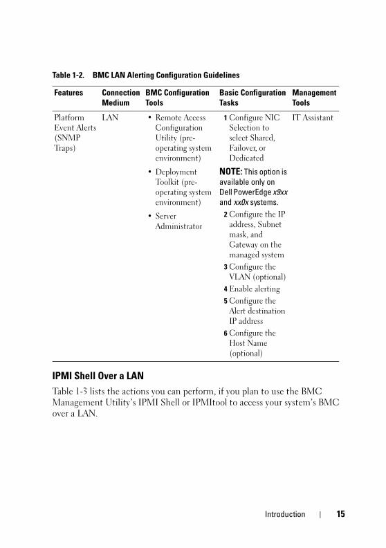
IPMI Shell Over a LAN
Table 1-3 lists the actions you can perform, if you plan to use the BMC
Management Utility’s IPMI Shell or IPMItool to access your system’s BMC
over a LAN.
Table 1-2. BMC LAN Alerting Configuration Guidelines
Features Connection Medium
BMC Configuration Tools
Basic Configuration Tasks
Management Tools
Platform
Event Alerts
(SNMP
Traps)
LAN • Remote Access
Configuration
Utility (pre-
operating system
environment)
• Deployment
Toolkit (pre-
operating system
environment)
• Server
Administrator
1 Configure NIC
Selection to
select Shared,
Failover, or
Dedicated
NOTE: This option is available only on Dell PowerEdge x9xx and xx0x systems.
2 Configure the IP
address, Subnet
mask, and
Gateway on the
managed system
3 Configure the
VLAN (optional)
4 Enable alerting
5 Configure the
Alert destination
IP address
6 Configure the
Host Name
(optional)
IT Assistant
16 Introduction
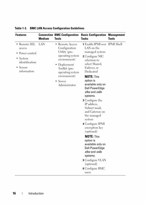
Table 1-3. BMC LAN Access Configuration Guidelines
Features Connection Medium
BMC Configuration Tools
Basic Configuration Tasks
Management Tools
• Remote SEL
access
• Power control
• System
identification
• Sensor
information
LAN • Remote Access
Configuration
Utility (pre-
operating system
environment)
• Deployment
Toolkit (pre-
operating system
environment)
• Server
Administrator
1 Enable IPMI over
LAN on the
managed system
2 Configure NIC
selection to
select Shared,
Failover, or
Dedicated
NOTE: This option is available only on Dell PowerEdge x9xx and xx0x systems.
3 Configure the
IP address,
Subnet mask,
and Gateway on
the managed
system
4 Configure IPMI
encryption key
(optional)
NOTE: This option is available only on Dell PowerEdge x9xx and xx0x systems.
5 Configure VLAN
(optional)
6 Configure BMC
users
IPMI Shell
Introduction 17
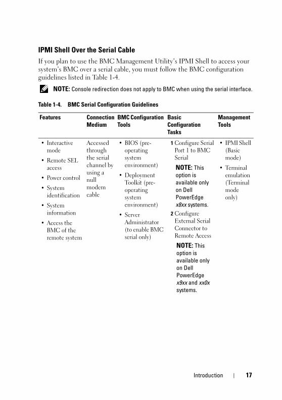
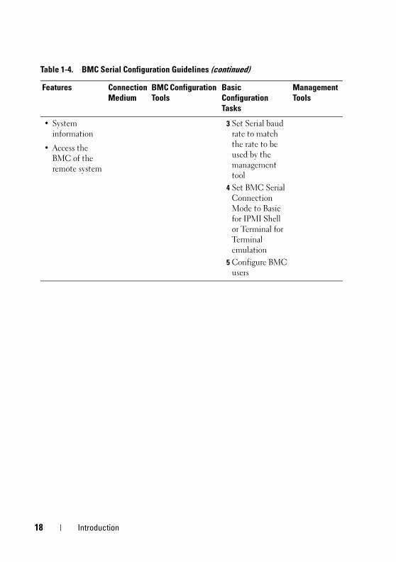
IPMI Shell Over the Serial Cable
If you plan to use the BMC Management Utility’s IPMI Shell to access your
system’s BMC over a serial cable, you must follow the BMC configuration
guidelines listed in Table 1-4.
NOTE: Console redirection does not apply to BMC when using the serial interface.
Table 1-4. BMC Serial Configuration Guidelines
Features Connection Medium
BMC Configuration Tools
Basic Configuration Tasks
Management Tools
• Interactive
mode
• Remote SEL
access
• Power control
• System
identification
• System
information
• Access the
BMC of the
remote system
Accessed
through
the serial
channel by
using a
null
modem
cable
• BIOS (pre-
operating
system
environment)
• Deployment
Toolkit (pre-
operating
system
environment)
• Server
Administrator
(to enable BMC
serial only)
1 Configure Serial
Port 1 to BMC
Serial
NOTE: This option is available only on Dell PowerEdge x8xx systems.
2 Configure
External Serial
Connector to
Remote Access
NOTE: This option is available only on Dell PowerEdge x9xx and xx0x systems.
• IPMI Shell
(Basic
mode)
• Terminal
emulation
(Terminal
mode
only)
18 Introduction
• System
information
• Access the
BMC of the
remote system
3 Set Serial baud
rate to match
the rate to be
used by the
management
tool
4 Set BMC Serial
Connection
Mode to Basic
for IPMI Shell
or Terminal for
Terminal
emulation
5 Configure BMC
users
Table 1-4. BMC Serial Configuration Guidelines (continued)
Features Connection Medium
BMC Configuration Tools
Basic Configuration Tasks
Management Tools

Introduction 19
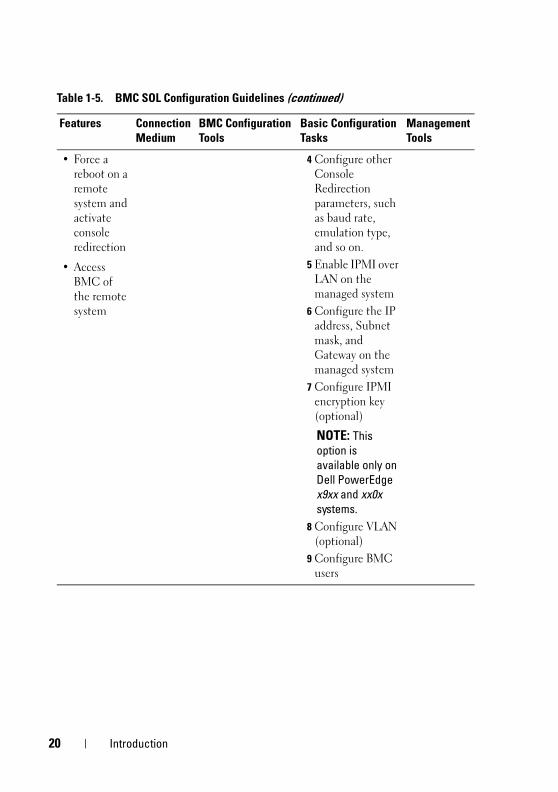
SOL Proxy Over a LAN
If you plan to use the BMC Management Utility’s SOL Proxy to access your
system’s console over a LAN, you must follow the BMC configuration
guidelines listed in Table 1-5.
Table 1-5. BMC SOL Configuration Guidelines
Features Connection Medium
BMC Configuration Tools
Basic Configuration Tasks
Management Tools
• Text Utility
console
redirection
• Remote
BIOS setup
• Microsoft
text
console
redirection
• Linux text
console
redirection
LAN • BIOS (pre-
operating system
environment)
• Remote Access
Configuration
Utility (pre-
operating system
environment)
• Deployment
Toolkit (pre-
operating system
environment)
• Server
Administrator
1 Configure Serial
Port 1 to BMC
NIC
NOTE: This option is available only on Dell PowerEdge x8xx systems.
2 Configure BIOS
console
redirection to
Serial Port 1.
NOTE: This option is available only on Dell PowerEdge x9xx systems.
3 Configure
Console
Redirection to
On with Console
Redirection via
COM2
NOTE: This option is available only on Dell PowerEdge x9xx and xx0x systems.
• SOL
Proxy
• IPMI
Shell
20 Introduction
• Force a
reboot on a
remote
system and
activate
console
redirection
• Access
BMC of
the remote
system
4 Configure other
Console
Redirection
parameters, such
as baud rate,
emulation type,
and so on.
5 Enable IPMI over
LAN on the
managed system
6 Configure the IP
address, Subnet
mask, and
Gateway on the
managed system
7 Configure IPMI
encryption key
(optional)
NOTE: This option is available only on Dell PowerEdge x9xx and xx0x systems.
8 Configure VLAN
(optional)
9 Configure BMC
users
Table 1-5. BMC SOL Configuration Guidelines (continued)
Features Connection Medium
BMC Configuration Tools
Basic Configuration Tasks
Management Tools
Introduction 21
BMC Configuration and Management Tools
Using the Remote Access Configuration Utility
The Remote Access Configuration Utility provides basic BMC setup and
configuration functions that can be accessed during system boot. Use the
Remote Access Configuration Utility for initial BMC setup and configuration
only. For advanced configuration tasks, you must use the Deployment Toolkit
SYSCFG utility or Server Administrator Version 2.0 or later.
NOTE: The Remote Access Configuration Utility is called the BMC Setup Module in the Dell PowerEdge x8xx systems.
Using Deployment Toolkit
The Deployment Toolkit (DTK) SYSCFG utility provides a powerful
Microsoft Windows Preinstallation Environment (PE) and Linux
command-line interface for locally configuring your system’s BMC as part of
an initial deployment. Use the DTK SYSCFG utility to set all supported
BMC features. Additionally, you can use the Deployment Toolkit utilities to
capture and replicate system settings on similar systems. See "Configuring
Your BMC Using the Deployment Toolkit Utility" on page 36 for more
information on how to install and set up the DTK SYSCFG utility.
Using the BMC Management Utility
The BMC Management Utility provides a command-line interface to your
remote management station to manage BMC-supported functions. Use the
BMC Management Utility to manage your BMC from a remote management
station and as your managed system’s emergency management console. The
utility gives you the option of using either a command line interface (IPMI
Shell) or a SOL Proxy to access and manage the BMC. To use the BMC
Management Utility, you must perform the following tasks:
• Configure BMC using the Remote Access Configuration Utility, the DTK
SYSCFG utility, or Server Administrator.
• Install the BMC Management Utility on a management station.
See "Configuring Your Managed System" for instructions on configuring the
BMC on a managed system in preparation for using the BMC Management
Utility.

22 Introduction
Using Server Administrator
The Server Administrator provides a convenient and easy-to-use GUI for
remotely configuring or managing your system’s BMC on a system running a
supported operating system. You can use the Server Administrator to
configure the most relevant BMC features, such as Platform Event Filter
(PEF) parameters and alert destinations. Additionally, Server Administrator
can be used as a command line interface. Server Administrator requires that
the system has an operating system installed and functioning. As a result,
Server Administrator is best suited for everyday BMC management tasks, and
is not an option for performing pre-boot setup or accessing the BMC as an
emergency management console. To use Server Administrator, you must
perform the following tasks:
• Install Server Administrator on the managed system.
• Access the Server Administrator home page remotely or locally from a
supported browser on a management station.
• Configure BMC remotely or locally on the managed system.
See the Dell OpenManage™ Server Administrator User’s Guide and Command
line Interface User’s Guide on the Dell Support website at support.dell.com,
the Dell Systems Documentation CD, or the Dell Systems Management Tools
and Documentation DVD for more information about using Server
Administrator to configure and manage your system BMC.
Other Dell Documents You May NeedIn addition to this User's Guide, you can find the following guides either on
the Dell Support website at support.dell.com or on the Dell Systems
Documentation CD and the Dell Systems Management Tools and
Documentation DVD:
• The Dell OpenManage Quick Installation Guide provides additional
information about installing the BMC Management Utility on a
management station.
• The Dell OpenManage Server Administrator User’s Guide provides
additional information about using Server Administrator to manage your
system’s BMC.
• The Dell OpenManage Deployment Toolkit User’s Guide provides
additional information about installing and using the DTK utilities.
Introduction 23
• The Dell OpenManage Deployment Toolkit Command Line Interface
Reference Guide provides a complete list of all valid BMC-related
command-line options, suboptions, and arguments.
• The Dell OpenManage IT Assistant User’s Guide provides information
about how to monitor and manage a large number of client and server
systems on a local area network (LAN) or wide area network (WAN).
• The Dell system User’s Guide provides supplemental information about
configuring your BIOS settings with the System Setup Program, as well as
instructions for configuring your system to use console redirection.
Additionally, the Dell OpenManage readme.txt file provides the latest
available information for the installation and operation of the programs and
utilities used to manage your system through the BMC. The readme is
available on the Dell Systems Console and Agent CD, the Dell Systems
Management Tools and Documentation DVD, and on the Dell Support
website at support.dell.com.
Obtaining Technical AssistanceIf at any time you do not understand a procedure described in this guide or if
your product does not perform as expected, help tools are available to assist
you. For more information about these help tools, see "Getting Help" in your
system's Installation and Troubleshooting Guide or the Hardware Owner’s
Manual.
Additionally, Dell Enterprise Training and Certification is available; see
www.dell.com/training for more information. This service may not be offered
in all locations.

24 Introduction
Configuring Your Managed System 25
Configuring Your Managed SystemBefore using the BMC Management Utility, configure certain items, such as
the necessary system BIOS, network, Intelligent Platform Management
Interface (IPMI) encryption key, and serial connection settings, depending on
the functionality to be performed, to enable access to the BMC.
NOTE: The IPMI encryption key is a public key that is used to generate an encryption key for use between the firmware and the application.
In addition, to utilize the BMC Management Utility IPMI serial functions,
you must have a working connection between the management station and
the correct serial I/O port of the target BMC, using a null modem cable.
This section describes the basic procedures you must perform to prepare your
BMC to be accessed and managed using the BMC Management Utility.
The following procedures are described:
• BIOS Configuration
• Baseboard Management Controller Configuration
• Configuring your BMC with the Dell™ OpenManage™ Deployment
ToolKit (DTK) SYSCFG utility
• Configuring your BMC with Dell OpenManage Server Administrator
BIOS ConfigurationFor most configurations, you must configure the serial port settings and the
console redirection settings in your system BIOS before you can use the BMC
Management Utility. To configure the necessary system BIOS setting, your
must enter the System Setup Program. The BIOS settings can also be
configured using the Deployment Toolkit or the Server Administrator.
NOTE: For more information about configuring BIOS settings, see your system User’s Guide.

26 Configuring Your Managed System
Configuring System BIOS in Dell PowerEdge™ x8xx/x9xx Systems
1 Turn on or restart your system.
2 Press <F2> immediately after you see the following message:
<F2> = Setup
The System Setup screen appears.
NOTE: If your operating system begins to load before you press <F2>, allow the system to finish booting, and then restart your system and try again.
3 Use the up- and down-arrow keys to navigate to the Integrated Devices
field and press <Enter>.
4 Use the up- and down-arrow keys to navigate to the Serial Port 1 field and
press <Enter>.
5 Use the space bar to select the serial port option.
The options are COM1, COM3, BMC Serial, BMC NIC, Off, and RAC
(if an optional RAC is installed in the system).
To use BMC, serial port 1 uses the COM1 address and communication
can be through the serial port or the integrated shared NIC. RAC control
uses only the COM1 address. Off and COM3 are not available options
when Console Redirection is set to use serial port 1.
a Select BMC Serial if you are planning to access the BMC through the
serial cable connection.
b Select BMC NIC if you are using SOL proxy and are planning to
access the BMC over a shared LAN.
6 Press <Enter> to return to the System Setup screen.
7 Use the up- and down-arrow keys to navigate to the Console Redirection
field and press <Enter>.
8 Use the up- and down-arrow keys to navigate to the Console Redirection
option and then use the space bar to set the console redirection feature to
Serial Port 1. Optionally, you can also enable Redirection after Boot.
9 Use the up- and down- arrow keys to navigate to the Failsafe Baud Rate
option and then use the space bar to set the console failsafe baud rate,
if applicable.

Configuring Your Managed System 27
10 Use the up- and down-arrow keys to navigate to the Remote Terminal
Type option and then use the space bar to select either VT 100/VT 200 or
ANSI, if applicable.
11 Press <Enter> to return to the System Setup screen.
12 Press <Esc> to exit the System Setup program. The Exit screen displays
the following options:
• Save Changes and Exit
• Discard Changes and Exit
• Return to Setup
13 Choose the appropriate option and exit the system setup.
Configuring System BIOS in Dell PowerEdge™ x9xx and xx0x Systems
1 Turn on and restart your system.
2 Press <F2> immediately after you see the following message:
<F2> = Setup
The System Setup screen appears.
NOTE: If your operating system begins to load before you press <F2>, allow the system to finish booting, and then restart your system and try again.
3 Use the up- and down-arrow keys to navigate to the Serial
Communication field and press <Enter>.
4 Use the spacebar to select the appropriate serial communication option.
5 Press <Enter> to select the appropriate option for Console Redirection.
The following options are available:
On without Console Redirection: COM1 and COM2 are enabled and
available for use by the operating system or applications. Console
redirection is disabled. This is the default option.
On with Console Redirection via COM1: When BIOS console
redirection is enabled through COM1, the COM1 port is not available to
applications through the operating system.
On with Console Redirection via COM2: When BIOS console
redirection is enabled through COM2, the COM2 port is not available to
applications through the operating system.

28 Configuring Your Managed System
Off: COM1 and COM2 are both disabled and not available for use by the
operating system or applications. BIOS Console redirection is disabled.
NOTE: Select On with Console Redirection via COM2 to use Console Redirection with SOL.
6 Use the up- and down-arrow keys to navigate to the External Serial
Communication field and press <Enter>.
7 Use the spacebar to select the appropriate external serial communication
option.
The available options are COM1, COM2, and Remote Access.
The default option is COM1.
NOTE: Select Remote Access to access the BMC through the serial cable connection. This option can be set to any value for using SOL and accessing the BMC over LAN.
8 Press <Enter> to select.
9 If required, use the spacebar to navigate to and change the settings for
Redirection after Boot.
10 Use the up- and down-arrow keys to navigate to the Failsafe Baud Rate
option and then use the space bar to set the console failsafe baud rate,
if applicable.
11 Use the up- and down-arrow keys navigate to the Remote Terminal Type
option and then use the space bar to select either VT 100/VT 200 or ANSI,
if applicable.
12 Press <Enter> to return to the System Setup screen.
13 Press <Esc> to exit the System Setup program. The Exit screen displays
the following options:
• Save Changes and Exit
• Discard Changes and Exit
• Return to Setup
NOTE: For most options, any changes that you make are recorded but do not take effect until you restart the system.
NOTE: Press <F1> to display the help file for the System Setup program.
Configuring Your Managed System 29
Using BIOS Console Redirection With SOL Proxy
Console redirection allows maintenance of a system from a remote location
by redirecting keyboard input and output through the serial port. Any
console-based feature or operating system can then be used to access the
server. DR-DOS, Linux (init 3) and Windows®
Special Administrative
Console (SAC) are examples of operating systems and consoles that can be
used to access the server.
By default, some operating systems, such as Windows Server™ 2003, are
automatically configured to send text console output to the BIOS. Manual
configuration of the Redirection after Boot feature through the system BIOS
may not be visible to the operating system. This results in both, the operating
system feature and the BIOS redirection feature, being enabled. Depending
on the operating system and its setup, the results may vary. Dell recommends
the following steps as good practice:
DR-DOS: Do not configure DR-DOS for serial console output. Enable
console redirection after reboot in system BIOS.
Windows Special Administrative Console (SAC): Do not configure
Windows SAC for serial console redirection. Enable console redirection after
reboot in system BIOS.
Linux: Do not configure console redirection after rebooting the system BIOS.
Do the tasks listed in the "Installation and Setup for Linux Operating
Systems" section, to configure Linux for console redirection.
NOTE: See" Escape Key Sequences" for a list of keystrokes to be used for BIOS Setup operations from a serial terminal.
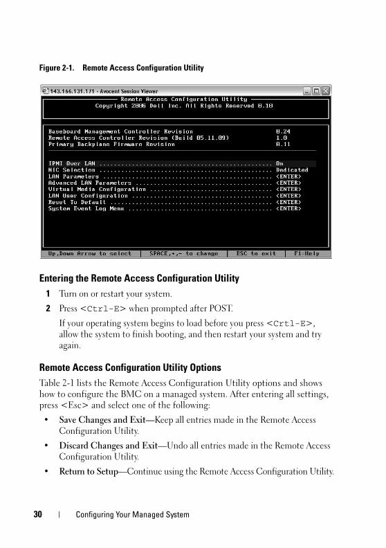
Baseboard Management Controller ConfigurationYou can perform basic BMC configuration using the Remote Access
Configuration Utility during system startup. See Figure 2-1. For more
advanced configuration options, see the instructions for the DTK SYSCFG
utility in the Deployment Toolkit User’s Guide.
30 Configuring Your Managed System
Figure 2-1. Remote Access Configuration Utility
Entering the Remote Access Configuration Utility
1 Turn on or restart your system.
2 Press <Ctrl-E> when prompted after POST.
If your operating system begins to load before you press <Crtl-E>,
allow the system to finish booting, and then restart your system and try
again.
Remote Access Configuration Utility Options
Table 2-1 lists the Remote Access Configuration Utility options and shows
how to configure the BMC on a managed system. After entering all settings,
press <Esc> and select one of the following:
• Save Changes and Exit—Keep all entries made in the Remote Access
Configuration Utility.
• Discard Changes and Exit—Undo all entries made in the Remote Access
Configuration Utility.
• Return to Setup—Continue using the Remote Access Configuration Utility.
Configuring Your Managed System 31
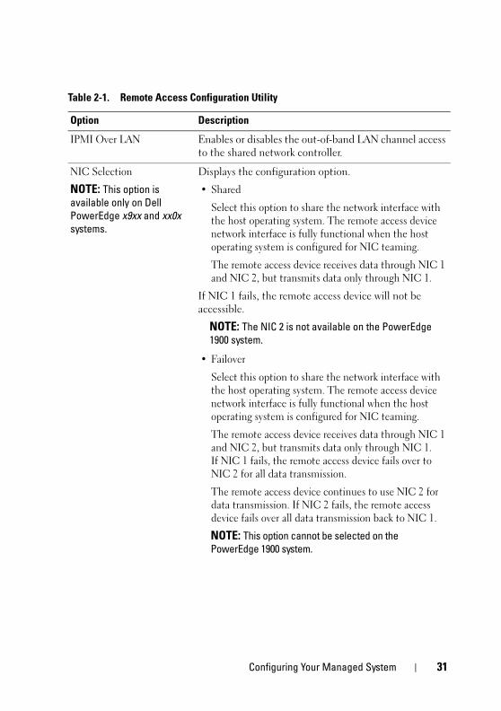
Table 2-1. Remote Access Configuration Utility
Option Description
IPMI Over LAN Enables or disables the out-of-band LAN channel access
to the shared network controller.
NIC Selection
NOTE: This option is available only on Dell PowerEdge x9xx and xx0x systems.
Displays the configuration option.
• Shared
Select this option to share the network interface with
the host operating system. The remote access device
network interface is fully functional when the host
operating system is configured for NIC teaming.
The remote access device receives data through NIC 1
and NIC 2, but transmits data only through NIC 1.
If NIC 1 fails, the remote access device will not be
accessible.
NOTE: The NIC 2 is not available on the PowerEdge 1900 system.
• Failover
Select this option to share the network interface with
the host operating system. The remote access device
network interface is fully functional when the host
operating system is configured for NIC teaming.
The remote access device receives data through NIC 1
and NIC 2, but transmits data only through NIC 1.
If NIC 1 fails, the remote access device fails over to
NIC 2 for all data transmission.
The remote access device continues to use NIC 2 for
data transmission. If NIC 2 fails, the remote access
device fails over all data transmission back to NIC 1.
NOTE: This option cannot be selected on the PowerEdge 1900 system.
32 Configuring Your Managed System
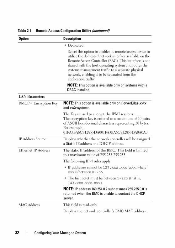
• Dedicated
Select this option to enable the remote access device to
utilize the dedicated network interface available on the
Remote Access Controller (RAC). This interface is not
shared with the host operating system and routes the
systems management traffic to a separate physical
network, enabling it to be separated from the
application traffic.
NOTE: This option is available only on systems with a DRAC installed.
LAN Parameters
RMCP+ Encryption Key NOTE: This option is available only on PowerEdge x9xx and xx0x systems.
The Key is used to encrypt the IPMI sessions.
The encryption key is entered as a maximum of 20 pairs
of ASCII hexadecimal characters representing 20 bytes.
For example,
01FA3BA6C812855DA001FA3BA6C812855DA0A0A0.
IP Address Source Displays whether the network controller will be assigned
a Static IP address or a DHCP address.
Ethernet IP Address The static IP address of the BMC. This field is limited
to a maximum value of 255.255.255.255.
The following IPv4 rules apply:
• IP addresses cannot be 127.xxx.xxx.xxx, where
xxx is between 0-255.
• The first octet must be between 1-223 (that is,
143.xxx.xxx.xxx)
NOTE: IP address 169.254.0.2 subnet mask 255.255.0.0 is returned when the BMC is unable to contact the DHCP server.
MAC Address This field is read-only.
Displays the network controller’s BMC MAC address.
Table 2-1. Remote Access Configuration Utility (continued)
Option Description
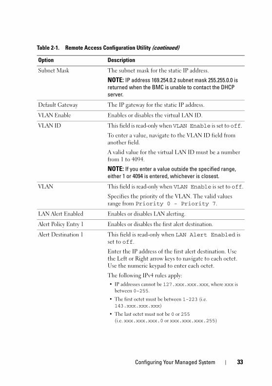
Configuring Your Managed System 33
Subnet Mask The subnet mask for the static IP address.
NOTE: IP address 169.254.0.2 subnet mask 255.255.0.0 is returned when the BMC is unable to contact the DHCP server.
Default Gateway The IP gateway for the static IP address.
VLAN Enable Enables or disables the virtual LAN ID.
VLAN ID This field is read-only when VLAN Enable is set to off.
To enter a value, navigate to the VLAN ID field from
another field.
A valid value for the virtual LAN ID must be a number
from 1 to 4094.
NOTE: If you enter a value outside the specified range, either 1 or 4094 is entered, whichever is closest.
VLAN This field is read-only when VLAN Enable is set to off.
Specifies the priority of the VLAN. The valid values
range from Priority 0 - Priority 7.
LAN Alert Enabled Enables or disables LAN alerting.
Alert Policy Entry 1 Enables or disables the first alert destination.
Alert Destination 1 This field is read-only when LAN Alert Enabled is
set to off.
Enter the IP address of the first alert destination. Use
the Left or Right arrow keys to navigate to each octet.
Use the numeric keypad to enter each octet.
The following IPv4 rules apply:
• IP addresses cannot be 127.xxx.xxx.xxx, where xxx is
between 0-255.
• The first octet must be between 1-223 (i.e.
143.xxx.xxx.xxx)
• The last octet must not be 0 or 255
(i.e. xxx.xxx.xxx.0 or xxx.xxx.xxx.255)
Table 2-1. Remote Access Configuration Utility (continued)
Option Description
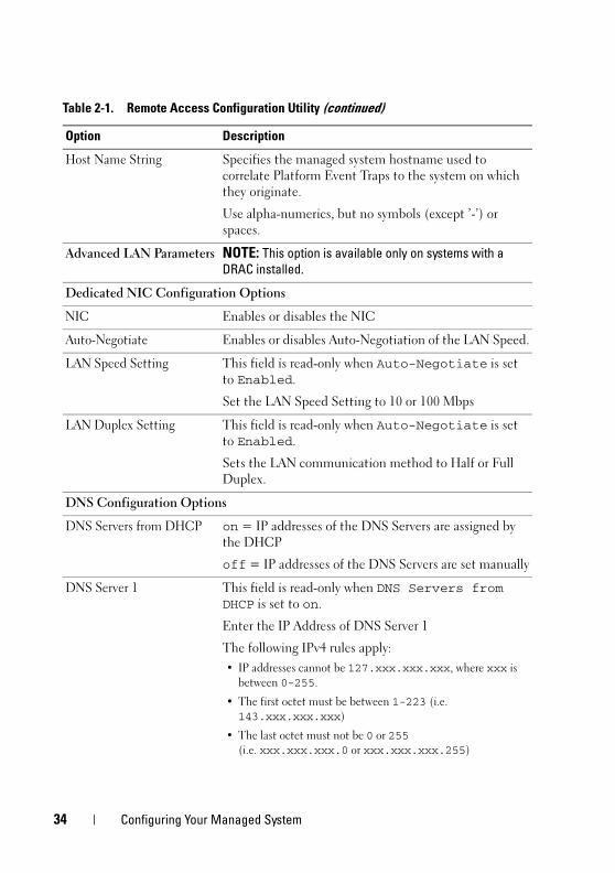
34 Configuring Your Managed System
Host Name String Specifies the managed system hostname used to
correlate Platform Event Traps to the system on which
they originate.
Use alpha-numerics, but no symbols (except ’-’) or
spaces.
Advanced LAN Parameters NOTE: This option is available only on systems with a DRAC installed.
Dedicated NIC Configuration Options
NIC Enables or disables the NIC
Auto-Negotiate Enables or disables Auto-Negotiation of the LAN Speed.
LAN Speed Setting This field is read-only when Auto-Negotiate is set
to Enabled.
Set the LAN Speed Setting to 10 or 100 Mbps
LAN Duplex Setting This field is read-only when Auto-Negotiate is set
to Enabled.
Sets the LAN communication method to Half or Full
Duplex.
DNS Configuration Options
DNS Servers from DHCP on = IP addresses of the DNS Servers are assigned by
the DHCP
off = IP addresses of the DNS Servers are set manually
DNS Server 1 This field is read-only when DNS Servers from DHCP is set to on.
Enter the IP Address of DNS Server 1
The following IPv4 rules apply:
• IP addresses cannot be 127.xxx.xxx.xxx, where xxx is
between 0-255.
• The first octet must be between 1-223 (i.e.
143.xxx.xxx.xxx)
• The last octet must not be 0 or 255
(i.e. xxx.xxx.xxx.0 or xxx.xxx.xxx.255)
Table 2-1. Remote Access Configuration Utility (continued)
Option Description
Configuring Your Managed System 35
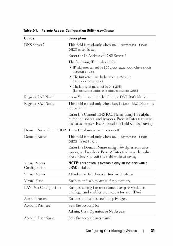
DNS Server 2 This field is read-only when DNS Servers from DHCP is set to on.
Enter the IP Address of DNS Server 2
The following IPv4 rules apply:
• IP addresses cannot be 127.xxx.xxx.xxx, where xxx is
between 0-255.
• The first octet must be between 1-223 (i.e.
143.xxx.xxx.xxx)
• The last octet must not be 0 or 255
(i.e. xxx.xxx.xxx.0 or xxx.xxx.xxx.255)
Register RAC Name on = You may enter the Current DNS RAC Name.
Register RAC Name This field is read-only when Register RAC Name is
set to off.
Enter the Current DNS RAC Name using 1-32 alpha-
numerics, spaces, and symbols. Press <Enter> to save
the value. Press <Esc> to exit the field without saving.
Domain Name from DHCP Turns the domain name on or off.
Domain Name This field is read-only when DNS Servers from DHCP is set to on.
Enter the Domain Name using 1-64 alpha-numerics,
spaces, and symbols. Press <Enter> to save the value.
Press <Esc> to exit the field without saving.
Virtual Media
Configuration
NOTE: This option is available only on systems with a DRAC installed.
Virtual Media Attaches or detaches a virtual media drive.
Virtual Flash Enables or disables virtual flash memory.
LAN User Configuration Enables setting the user name, user password, user
privilege, and enables user access for user ID=2.
Account Access Enables or disables account privileges.
Account Privilege Sets the account to:
Admin, User, Operator, or No Access
Account User Name Sets the account user name.
Table 2-1. Remote Access Configuration Utility (continued)
Option Description
36 Configuring Your Managed System
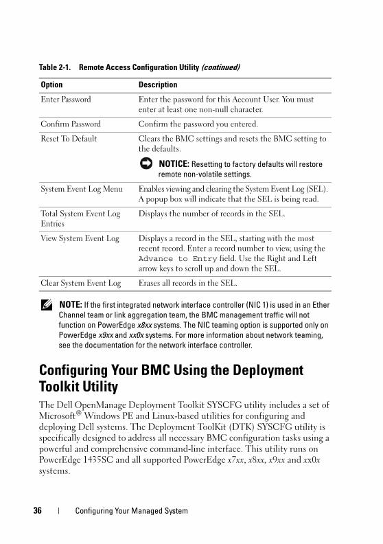
NOTE: If the first integrated network interface controller (NIC 1) is used in an Ether Channel team or link aggregation team, the BMC management traffic will not function on PowerEdge x8xx systems. The NIC teaming option is supported only on PowerEdge x9xx and xx0x systems. For more information about network teaming, see the documentation for the network interface controller.
Configuring Your BMC Using the Deployment Toolkit UtilityThe Dell OpenManage Deployment Toolkit SYSCFG utility includes a set of
Microsoft®
Windows PE and Linux-based utilities for configuring and
deploying Dell systems. The Deployment ToolKit (DTK) SYSCFG utility is
specifically designed to address all necessary BMC configuration tasks using a
powerful and comprehensive command-line interface. This utility runs on
PowerEdge 1435SC and all supported PowerEdge x7xx, x8xx, x9xx and xx0x
systems.
Enter Password Enter the password for this Account User. You must
enter at least one non-null character.
Confirm Password Confirm the password you entered.
Reset To Default Clears the BMC settings and resets the BMC setting to
the defaults.
NOTICE: Resetting to factory defaults will restore remote non-volatile settings.
System Event Log Menu Enables viewing and clearing the System Event Log (SEL).
A popup box will indicate that the SEL is being read.
Total System Event Log
Entries
Displays the number of records in the SEL.
View System Event Log Displays a record in the SEL, starting with the most
recent record. Enter a record number to view, using the
Advance to Entry field. Use the Right and Left
arrow keys to scroll up and down the SEL.
Clear System Event Log Erases all records in the SEL.
Table 2-1. Remote Access Configuration Utility (continued)
Option Description
Configuring Your Managed System 37
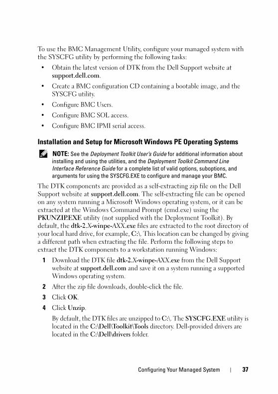
To use the BMC Management Utility, configure your managed system with
the SYSCFG utility by performing the following tasks:
• Obtain the latest version of DTK from the Dell Support website at
support.dell.com.
• Create a BMC configuration CD containing a bootable image, and the
SYSCFG utility.
• Configure BMC Users.
• Configure BMC SOL access.
• Configure BMC IPMI serial access.
Installation and Setup for Microsoft Windows PE Operating Systems
NOTE: See the Deployment Toolkit User’s Guide for additional information about installing and using the utilities, and the Deployment Toolkit Command Line Interface Reference Guide for a complete list of valid options, suboptions, and arguments for using the SYSCFG.EXE to configure and manage your BMC.
The DTK components are provided as a self-extracting zip file on the Dell
Support website at support.dell.com. The self-extracting file can be opened
on any system running a Microsoft Windows operating system, or it can be
extracted at the Windows Command Prompt (cmd.exe) using the
PKUNZIP.EXE utility (not supplied with the Deployment Toolkit). By
default, the dtk-2.X-winpe-AXX.exe files are extracted to the root directory of
your local hard drive, for example, C:\. This location can be changed by giving
a different path when extracting the file. Perform the following steps to
extract the DTK components to a workstation running Windows:
1 Download the DTK file dtk-2.X-winpe-AXX.exe from the Dell Support
website at support.dell.com and save it on a system running a supported
Windows operating system.
2 After the zip file downloads, double-click the file.
3 Click OK.
4 Click Unzip.
By default, the DTK files are unzipped to C:\. The SYSCFG.EXE utility is
located in the C:\Dell\Toolkit\Tools directory. Dell-provided drivers are
located in the C:\Dell\drivers folder.

38 Configuring Your Managed System
Creating a Bootable Windows PE 2005 ISO Image
NOTE: See "Creating a Bootable Windows PE 2.0 ISO Image" on page 40 for information on creating a bootable CD for Windows PE 2.0.
Integration of DTK Directory Structure in the Windows PE Build
This task involves a five-step process:
1 Integrating DTK tools and scripts: Copy the folder \Dell that you
unzipped from the Dell-supplied zip file to DellWinPEBuild, or extract
the Dell-supplied file directly into the Windows PE build.
2 Installing necessary drivers into Windows PE: Execute
\Dell\Drivers\DRIVERINST.BAT with two required arguments:
• Path to DellWinPEBuild
• Path where the Dell-provided drivers are located. These drivers can be
found in the DTK zip file under the \Dell\drivers folder.
3 Adding support for mass storage drivers into Windows PE:
NOTE: You must implement this step to ensure mass storage drivers are installed into Windows PE.
In the winpeoem.sif file (available under I386\SYSTEM32 in your
Windows PE directory), edit the following text to remove the semicolons
from the Oem Driver Params section and append the directory
names for the Dell-mass storage drivers:
OemDriverRoot=""OemDriverDirs=MRAID, PERC4IM, PERC5, SAS5
NOTE: For your reference, a sample winpeoem.sif file is available under \Dell\Toolkit\template\Configs.
4 Starting required services: The mr2kserv service should be installed and
started for RAID to function; the racsvc service should be installed and
started for RACADM to function. For details on how to start the required
services, see the sample winbom.ini file under
\Dell\Toolkit\template\Configs.
NOTE: When booting the target system, ensure that the RAC and the mr2kserv services are running.
Configuring Your Managed System 39
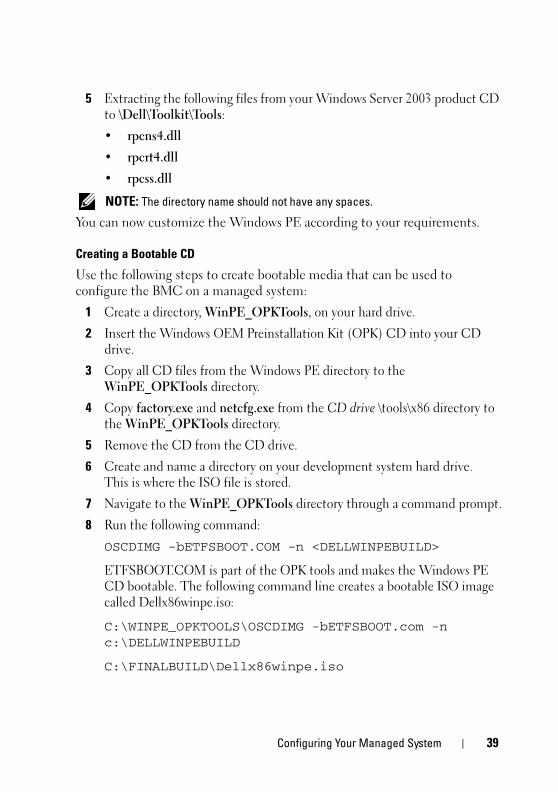
5 Extracting the following files from your Windows Server 2003 product CD
to \Dell\Toolkit\Tools:
• rpcns4.dll
• rpcrt4.dll
• rpcss.dll
NOTE: The directory name should not have any spaces.
You can now customize the Windows PE according to your requirements.
Creating a Bootable CD
Use the following steps to create bootable media that can be used to
configure the BMC on a managed system:
1 Create a directory, WinPE_OPKTools, on your hard drive.
2 Insert the Windows OEM Preinstallation Kit (OPK) CD into your CD
drive.
3 Copy all CD files from the Windows PE directory to the
WinPE_OPKTools directory.
4 Copy factory.exe and netcfg.exe from the CD drive \tools\x86 directory to
the WinPE_OPKTools directory.
5 Remove the CD from the CD drive.
6 Create and name a directory on your development system hard drive.
This is where the ISO file is stored.
7 Navigate to the WinPE_OPKTools directory through a command prompt.
8 Run the following command:
OSCDIMG -bETFSBOOT.COM -n <DELLWINPEBUILD>
ETFSBOOT.COM is part of the OPK tools and makes the Windows PE
CD bootable. The following command line creates a bootable ISO image
called Dellx86winpe.iso:
C:\WINPE_OPKTOOLS\OSCDIMG -bETFSBOOT.com -n c:\DELLWINPEBUILD
C:\FINALBUILD\Dellx86winpe.iso
40 Configuring Your Managed System
9 Copy the SYSCFG.EXE utility to the root of the directory.
10 After you create an ISO image, you can use any CD-burning software to
burn the image onto a CD.
You are now ready to use your bootable CD to configure the BMC on a
managed system. See the Deployment Toolkit User’s Guide for additional
information.
Creating a Bootable Windows PE 2.0 ISO Image
If you are using Windows PE 2.0, download Windows Administrative
Installation Kit (WAIK) from the Microsoft website. By default, WAIK is copied
to the C:\Program Files\Windows AIK directory.
Integration of DTK Directory Structure in Windows PE Build
DTK provides a script, VPE_driverinst.bat, to pre-install the Dell drivers into
a base Windows PE 2.0 image offline. Use the following steps to execute
this script:
1 Open a command prompt on your system and change the directory to the
location of VPE_driverinst.bat. For example:
cd C:\Dell\Drivers\winpe2.x
2 Execute VPE_driverinst.bat with two required arguments
<WINPEPATH> and <DTKPATH>. For example:
VPE_driverinst.bat <WINPEPATH> <DTKPATH>
Where <WINPEPATH> is the destination path to create the directory
structure for Windows PE 2.0 and <DTKPATH> is the path to Dell
drivers in the extracted DTK toolkit. For example:
VPE_driverinst.bat C:\vistaPE_x86 C:\DELL\DRIVERS
NOTE: <WINPEPATH> is passed as the destination to the WAIK command copype.cmd. The destination folder C:\vistaPE_x86 is created as part of the process, and should not already exist.
Configuring Your Managed System 41
Creating a Bootable CD
Use the following steps to create bootable media:
1 Click Start, navigate to All Programs! Microsoft Windows AIK.
2 Click Windows PE Tools Command Prompt to open a command prompt
window.
3 Run the following command:
oscdimg -n -bc:\vistaPE_x86\etfsboot.com c:\vistaPE_x86\ISO c:\vistaPE_x86\WinPE2.0.iso
This command creates a CD bootable ISO image called WinPE2.0.iso.
4 You can use any CD burning software to burn the image onto a CD.
You are now ready to use your bootable CD to configure the BMC on a
managed system. See the Deployment Toolkit User’s Guide for additional
information.
Installation and Setup for Linux Operating Systems
NOTE: See the Deployment Toolkit User’s Guide for additional information about installing and using the utilities, and the Deployment Toolkit Command Line Interface Reference Guide for a complete list of all valid options, suboptions, and arguments for using the SYSCFG utility to configure and manage your BMC.
1 Obtain the ISO image of embedded Linux available on the Dell Support
website at support.dell.com.
2 Burn the ISO image using any commonly available CD burning software.
NOTE: When you create a bootable CD, this image is supplied to the CD burning software along with the complete deployment directory structure, which includes all necessary supporting files to perform the deployment.
3 The CD burning software creates an image of the self-bootable ISO image
and the deployment files on the CD.
4 Extract the contents of the ISO image to a folder on your hard drive.
5 Copy your custom scripts into the folder you created in step 4.
NOTE: Your scripts should also take care of copying miscellaneous items to unlock the CD, so that the CD can be mounted and ejected as required by the operating system’s installation process.
42 Configuring Your Managed System
6 In /mnt/cdrom/isolinux.cfg, the cd install section points to your
customized start-up script.
NOTE: The scripts that you copy into the CD will be copied to and run from the RAM disk. This task is done to ensure the CD is not locked. Ensure that your sample scripts have valid path names.
7 Copy the directory structure created in your work station, into the root
folder that you created in "step 4".
8 This folder contains the DTK CD files necessary for operating system
installation, and files required for replication.
9 Use the isolinux utility to burn the contents of the folder you created in
"step 7" to a CD and make it bootable.
10 Your ISO image is ready for booting.
Basic configuration
Before you can use the BMC Management Utility to remotely manage the
BMC on a managed system, you must perform some basic configuration
tasks. The Deployment Toolkit SYSCFG utility provides a powerful
command-line interface for performing the following configuration tasks:
• Configuring BMC users for the managed system
• Configuring the BMC IP address for IPMI LAN access and SOL access for
the managed system
• Configuring the BMC serial channel for IPMI serial access for the
managed system
NOTE: See the Deployment Toolkit User’s Guide for additional information about installing and using the Deployment Toolkit utilities, and the Command Line Interface Reference Guide for a complete list of valid options, suboptions, and arguments for using the SYSCFG utility to configure and manage your BMC.
Configuring Your Managed System 43
Configuring New BMC Users
The BMC is configured by default with user ID 2 set to username: root and password: calvin. It is highly recommended that you change the user name
and password when deploying your system.
1 Insert the bootable BMC configuration diskette or CD into the
appropriate drive of the system to be deployed and reboot the system.
2 To create a new user, at the command prompt, type:
syscfg username --userid=X --name=name
where X is a number between 2–10 and name is an ASCII string of 16 or
fewer characters.
Press <Enter> to execute the command line options.
3 To enable the new user ID, at the command prompt, type:
syscfg useraction --userid=X --action=enable
Press <Enter> to execute the command line options.
4 To set the password for a BMC user, at the command prompt, type:
syscfg passwordaction --action=setpassword --userid=X --password=password
where password is an ASCII string of 16 or fewer characters for both
PowerEdge x8xx and x9xx systems.
NOTICE: A password must be set for each BMC user. The BMC firmware does not allow access to users with null user names or passwords.
Press <Enter> to execute the command-line options.
5 To configure BMC user privilege, at the command prompt, type:
syscfg lanuseraccess --usrprivlmt=bmcuserprivilege where bmcuserprivilege=user, operator, administrator, noaccess
Press <Enter> to execute the command-line options.
44 Configuring Your Managed System
Configuring the BMC IP Address
1 Insert the Deployment Toolkit CD into the appropriate drive of the
system to be deployed and reboot the system.
2 To configure the BMC IP address source for the LAN channel to DHCP, at
the command prompt, type:
syscfg lcp --ipaddrsrc=dhcp
Press <Enter> to execute the command line options.
For a complete list of valid options, suboptions, and arguments for
configuring the BMC LAN channel see the Deployment Toolkit Command
Line Interface Reference Guide.
3 To configure the BMC IP address source for the LAN channel to a static
IP address, at the command prompt, type:
syscfg lcp --ipaddrsrc=static --ipaddress=XXX.XXX.XXX.XX --subnetmask=XXX.XXX.XXX.X --gateway=XXX.XXX.XXX.X
Press <Enter> to execute the command line options.
For a complete list of valid options, suboptions, and arguments for
configuring the BMC LAN channel see the Deployment Toolkit Command
Line Interface Reference Guide.
Configuring Your Managed System 45
Configuring the BMC Serial Channel Access
1 Insert the bootable diskette or CD into the appropriate drive of the system
to be deployed, and reboot the system.
2 To configure the serial port for BMC, at the command prompt, type:
syscfg scp --connectionmode=basic --msgcommbitrate=XXXXX
where XXXXX is the baud rate in bps.
Press <Enter> to execute the command line options.
3 To configure the terminal mode for BMC, at the command prompt, type:
syscfg scp --connectionmode=terminal --msgcommbitrate=XXXXX
where XXXXX is the baud rate in bps.
Press <Enter> to execute the command line options.
For a complete list of valid options, suboptions, and arguments for
configuring the BMC serial channel, see the Deployment Toolkit Command
Line Interface Reference Guide.
Configuring Your BMC Using Server AdministratorYou can also configure the BMC options using Server Administrator Version 5.3,
which is a one-to-one systems management software program that must be
installed on the managed system. Once installed, you can remotely access
Server Administrator from a management station with a supported browser to
perform BMC configuration tasks. See the Server Administrator User’s Guide
for more information about installing and using Server Administrator.
You can configure the BMC settings from either the Server Administrator
home page or from its command line interface. Users must have
Administrator privileges to access the BMC settings. Users logged in with
User or Power User group privileges can view the BMC information but
cannot change the settings.
See the Dell OpenManage Server Administrator Command Line Interface
User's Guide for information about configuring the BMC from the command line.

46 Configuring Your Managed System
When using Server Administrator, you can click Help on the global
navigation bar for more detailed information about the specific window you
are viewing. Server Administrator help is available for all windows accessible
to the user based on user privilege level and the specific hardware and
software groups that Server Administrator discovers on the managed system.
The Server Administrator Instrumentation Service allows you to manage
BMC features, such as, general BMC information, configuration of the LAN
and serial port, BMC users, and BIOS setup. To use Server Administrator to
configure the BMC on a managed system, perform the following steps:
NOTE: You must be logged in with Admin privileges to configure the BMC settings.
1 Log in to the Server Administrator home page for the target system.
2 Click the System object.
3 Click the Main System Chassis object.
4 Click the Remote Access object.
5 The BMC Information window is displayed.
6 Click the Configuration tab.
Under the Configuration tab, you can configure LAN, Serial Port, and
Serial Over LAN.
7 Click the Users tab.
Under the Users tab, you can modify the BMC user configuration.
NOTICE: A password must be set for each BMC user. The BMC firmware does not allow access to users with null user names or passwords.
Configuring BIOS in Server Administrator
To configure BIOS in Server Administrator, complete the following steps:
1 Click the System object.
2 Click the Main System Chassis object.
3 Click the BIOS object.
4 Click the Setup tab.
In the Setup tab, you can configure Console Redirection and Serial Port
communication parameters.
Configuring Your Managed System 47
Using Dell Remote Access Controller 5
The Dell Remote Access Controller (DRAC) 5 provides a Web-based
interface and RACADM (a command-line interface) that enables you to
configure the DRAC 5 properties and users, perform remote management
tasks, and troubleshoot a remote (managed) system for problems.
Configuring the Network and IPMI LAN Settings
NOTE: You must have Configure DRAC 5 permission to do the following steps.
NOTE: Most DHCP servers require a server to store a client identifier token in its reservations table. The client (DRAC 5, for example) must provide this token during DHCP negotiation. For RACs, the DRAC 5 supplies the client identifier option using a one-byte interface number (0) followed by a six-byte MAC address.
NOTE: If your managed system DRAC is configured in Shared or Shared with Failover mode and the DRAC is connected to a switch with Spanning Tree Protocol (STP) enabled, network clients will experience a 20- to 30-second delay in connectivity when the management station’s LOM link state changes during the STP convergence.
1 Access the DRAC 5 Web-based interface. See the Dell Remote Access
Controller 5 User’s Guide for more information.
2 Click Remote Access in the System tree.
3 Click the Configuration tab and then click Network.
4 Configure the DRAC 5 NIC settings in the Network Configuration page.
Table 2-1 describes the Network Settings and IPMI Settings on the
Network Configuration page.
5 Click Apply Changes when completed.
6 Click the appropriate Network Configuration page button to continue.
48 Configuring Your Managed System
Adding and Configuring DRAC 5 Users
Create unique users with specific administrative permissions (or role-based
authority) to manage your system with the DRAC 5 and maintain system
security. For additional security, you can also configure alerts that are e-mailed
to specific users when a specific system event occurs.
NOTE: You must have Configure DRAC 5 permission to do the following steps.
1 Expand the System tree and click Remote Access.
2 Click the Configuration tab and then click Users. The Users page appears,
which includes each user’s State, RAC Privilege, IPMI LAN Privilege, and
IPMI Serial Privilege.
3 Click a user ID number in the User ID column.
4 Configure the user’s properties and privileges in the User Configuration
page.
5 Click Apply Changes when completed.
6 Click the appropriate User Configuration page button to continue.
See the Dell Remote Access Controller 5 User’s Guide for more information on
the IPMI user privileges, DRAC group permissions, and the DRAC user
privilege settings.
Using the BMC Management Utility 49
Using the BMC Management UtilityThe BMC Management Utility is a collection of software applications that
enable remote management and configuration of Dell™ systems equipped
with a BMC. The BMC Management Utility includes the following
components:
• Command Line Interface (IPMI Shell and IPMItool)
Both IPMI Shell and IPMItool are scriptable console application programs
used for the control and management of remote systems using the IPMI
version 1.5 and later protocol. IPMI Shell and IPMItool support both serial
access and LAN access to the BMC.
The IPMI Shell can be used either in the generic CLI mode or the
interactive mode. The interactive mode allows for a dedicated connection
to a server and availability of all commands from the operating system
CLI. Using the IPMI Shell in this mode improves usability and reduces
time and traffic required for connecting and authenticating. The IPMItool
can only be used in the CLI mode.
Both IPMI Shell and IPMItool allow administration of one or more
managed systems from a command line shell, rather than a graphical user
interface (GUI). Use the IPMI Shell or IPMItool to perform the
following tasks:
– System power management
– System identifier control
– Access to the event log
– Access to the system sensors
– Enable Serial-over-LAN for a remote managed system
50 Using the BMC Management Utility
• Serial-Over-LAN Proxy (SOL Proxy)
The SOL Proxy is a telnet daemon that allows LAN-based administration
of remote systems using the Serial Over LAN (SOL) and IPMI protocols.
Any standard telnet client application, such as HyperTerminal on
Microsoft®
Windows®
or telnet on Linux, can be used to access the
daemon's features. SOL can be used either in the menu mode or
command mode. The SOL protocol coupled with the remote system's
BIOS console redirection allows administrators to remotely view and
change a managed system’s BIOS settings over a LAN. The Linux serial
console and Microsoft's EMS/SAC interfaces can also be accessed over a
LAN using SOL.
NOTICE: All versions of the Microsoft Windows operating system include Hilgraeve's HyperTerminal terminal emulation software. However, the included version does not provide many functions required during console redirection. Instead, you can use any terminal emulation software that supports VT100 or ANSI emulation mode. One example of a full VT100 or ANSI terminal emulator that supports console redirection on your system is Hilgraeve's HyperTerminal Private Edition 6.1 or later.
NOTE: See your system’s User’s Guide for more information about console redirection, including hardware and software requirements and instructions for configuring host and client systems to use console redirection.
NOTE: HyperTerminal and telnet settings must be consistent with the settings on the managed system. For example, the baud rates and terminal modes should match.
NOTE: The Windows "telnet" command that is run from a MS-DOS® prompt supports ANSI terminal emulation, and the BIOS needs to be set for ANSI emulation to display all the screens correctly.
Installing the BMC Management UtilityThe BMC Management Utility is installed on a management station to
remotely connect to the managed system’s BMC. See Figure 3-1.
Installation Prerequisites
Before using the BMC Management Utility, you must perform at least the
basic BIOS and BMC configuration tasks described in "Configuring Your
Managed System."
Using the BMC Management Utility 51
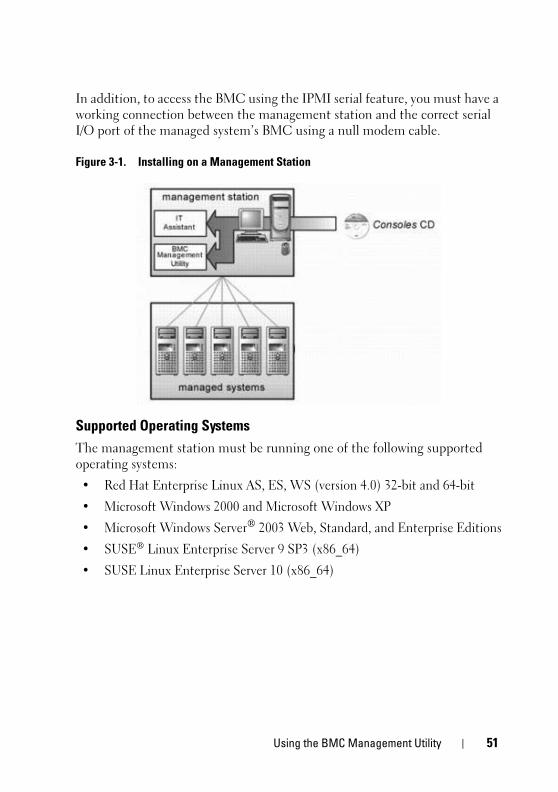
In addition, to access the BMC using the IPMI serial feature, you must have a
working connection between the management station and the correct serial
I/O port of the managed system’s BMC using a null modem cable.
Figure 3-1. Installing on a Management Station
Supported Operating Systems
The management station must be running one of the following supported
operating systems:
• Red Hat Enterprise Linux AS, ES, WS (version 4.0) 32-bit and 64-bit
• Microsoft Windows 2000 and Microsoft Windows XP
• Microsoft Windows Server®
2003 Web, Standard, and Enterprise Editions
• SUSE®
Linux Enterprise Server 9 SP3 (x86_64)
• SUSE Linux Enterprise Server 10 (x86_64)

52 Using the BMC Management Utility
Installation ProceduresThe following installation procedures provide step-by-step instructions for
installing and uninstalling the BMC Management Utility for each supported
operating system:
• Installing/uninstalling on systems running supported Windows operating
systems
• Installing/uninstalling on systems running supported Linux operating
systems
Installing on Systems Running Supported Windows Operating Systems
To install the BMC Management Utility on a management station running
the Windows operating system, perform the following steps:
1 Log in with administrator privileges to the system where you want to
install the systems management software components.
2 Exit any open application programs and disable any virus-scanning software.
3 Insert the Dell Systems Console and Agent CD or the Dell Systems
Management Tools and Documentation DVD into your system's CD or
DVD drive.
If the CD does not automatically start the setup program, click the Start
button, click Run, and then type x:\windows\setup.exe (where x is the
drive letter of your CD drive).
The Dell OpenManage Management Station Installation screen appears.
4 Click Install, Modify, Repair or Remove Management Station.
The Welcome to Install Wizard for Dell OpenManage Management
Station screen appears.
5 Click Next.
A software license agreement appears.
6 Select I accept the terms in the license agreement, if you agree.
The Setup Type screen appears.
7 Select Custom Setup and click Next.
The Custom Setup screen appears.
Using the BMC Management Utility 53
8 From the drop-down menu, which appears on the left side of BMC
Console, select This feature, and all subfeatures will be installed on the
local hard drive.
To accept the default directory path, click Next. Otherwise, click Browse
and navigate to the directory where you want to install your software, and
then click Next.
The Ready to Install the Program screen appears.
9 Ensure that all information is correct and click Install.
The Installing Dell OpenManage Management Station screen appears
and displays the status of the installation.
10 When installation is complete, the Install Wizard Completed screen
appears. Click Finish.
NOTE: Enable the virus scanning software after installation.
See the Dell OpenManage Installation and Security User’s Guide for
additional information about installing the BMC Management Utility on a
management station.
By default, the installation program copies the files to the following directory:
C:\Program Files\Dell\SysMgt\bmc.
The SOL Proxy service does not auto-start after installation. To start the SOL
Proxy service after installation, you can reboot the system (SOL Proxy
automatically starts on a reboot). To restart the SOL Proxy service on
Windows systems, complete the following steps:
1 Right-click My Computer and click Manage. The Computer
Management window is displayed.
2 Click Services and Applications and then click Services. Available services
are displayed to the right.
3 Locate DSM_BMU_SOLProxy in the list of services and right-click to
start the service.
Uninstalling on Systems Running Supported Windows Operating Systems
To uninstall the BMC Management Utility, use the Add/Remove Programs
utility in the Control Panel.
54 Using the BMC Management Utility
Installing on Systems Running Supported Linux Enterprise Operating Systems
To install the BMC Management Utility on a management station running
the Linux operating system:
1 Log in as root to the system where you want to install the management
station components.
2 If required, mount the Dell Systems Console and Agent CD using the
command:
mount /mnt/cdrom
3 Install the BMC Management Utility with the following command for
SUSE Linux Enterprise server:
rpm -ivh /linux/bmc/osabmcutil9g-SUSE*.rpm
or for Red Hat Enterprise Linux, use the following command:
rpm -ivh /linux/bmc/osabmcutil9g-RHEL*.rpm
By default, the installation program copies the files to the following
locations:
/etc/init.d/SOLPROXY.cfg
/etc/SOLPROXY.cfg
/usr/sbin/dsm_bmu_solproxy32d
/usr/sbin/solconfig
/usr/sbin/ipmish
The SOL Proxy will start automatically during system startup.
Alternatively, you can go to directory /etc/init.d and use the following
commands to manage the SOL Proxy service:
solproxy status
dsm_bmu_solproxy32d start
dsm_bmu_solproxy32d stop
solproxy restart
Using the BMC Management Utility 55
Uninstalling on Systems Running Supported Linux Enterprise Operating Systems
To uninstall the BMC Management Utility, perform the following steps:
1 Log in as root.
2 Enter either of the following commands to remove all the installed
packages from SUSE Linux Enterprise Server or Red Hat®
Enterprise
Linux®
.
rpm -e osabmcutil9g-SUSE*
rpm -e osabmcutil9g-RHEL*
If the BMC Management Utility has been uninstalled, you will receive a
success message.
IPMI ShellIPMI Shell is a CLI console application and has no GUI. Its commands and
options are specified using command line arguments only.
IPMI Shell supports out-of-band (OOB) access (over a LAN or through the
serial port) to a single system at a time, however, multiple IPMI Shell sessions
can run simultaneously on the same managed system. See Figure 3-2.
IPMI Shell allows a user with user-level BMC privileges to:
• Display the current power status.
• Display the 16-byte system GUID of the managed system.
• Display information from the system’s field replaceable unit (FRU).
• Display the BMC firmware information.
• Display summary information about the event log.
• Display logged events.
• Display current status of platform sensors.
• Enable or disable SOL.

56 Using the BMC Management Utility
In addition to the operations that can be performed by a user with user-level
BMC user privileges, IPMI Shell allows a user with operator-level and
administrator-level BMC user privileges to:
• Power on, reset, or power cycle a managed system.
• Simulate a hard power off on a managed system (forcing the system to
turn off without shutting down the operating system).
• Clear the system event log (SEL).
• Turn the blinking system identification LED on or off.
To facilitate command scripting, upon successful execution, IPMI Shell
terminates with an exit code of zero, and will output the execution results in a
parsable format. If an error is encountered, the program exits with a non-zero
error code and outputs the error in a parsable format. See "BMC
Management Utility Error Codes" for a complete list of possible BMC
Management Utility error codes.
Figure 3-2. IPMI Shell Diagram
Using the BMC Management Utility 57
Using IPMI Shell
To use IPMI Shell, perform the following steps:
On systems running a supported Microsoft Windows operating system:
1 Start a Command Prompt window.
2 Locate the ipmish.exe file. By default, ipmish.exe is located in the
directory: C:\Program Files\Dell\SysMgt\bmc.
3 Enter IPMI Shell commands (see "IPMI Shell Command Syntax") to
manage the remote system. See "IPMI Shell Commands" for a complete
list of valid options, commands, subcommands, and arguments.
On systems running a supported Linux operating system:
1 Start an operating system (OS) shell.
2 Enter IPMI Shell commands (see "IPMI Shell Command Syntax") to
manage the remote system. See "IPMI Shell Commands" for a complete
list of valid options, commands, subcommands, and arguments.
NOTE: The IPMI Shell will be located in /usr/sbin.
IPMI Shell Command Syntax
The general syntax of IPMI Shell CLI commands is as follows:
ipmish [global-options] … command [; command] …
The general usage for a command is:
command [subcommand] [command option and argument] …
Both global options and command-specific options are always in the following
form:
-option argument
For example:
-help
-max 20
-u John
58 Using the BMC Management Utility
Arguments with embedded tabs or spaces must be enclosed in matching
double quotation marks ("). For example:
-user "John Smith"
Every command has one default action. The default action is typically, but
not always, the equivalent of reading and displaying the current setting or
status for the command.
IPMI Shell Global Options
IPMI Shell has the following global options:
Running IPMISH over LAN Option -ip
Synopsis ipmish -ip bmc_ip_address | bmc_hostname -u username -p password
[-k KG value] <command>
Description
This option is used to establish a connection to a remote managed system
using the LAN channel. The IP port specified in installation (default value is 623)
is used unless another port has been configured.
NOTE: This global option cannot be used independently to connect to the BMC. One or more IPMISH commands must follow the option.
Options
-ip bmc_ip_address | bmc_hostname
Specifies the IP address or hostname of the remote managed system.
-u username
Specifies the BMC username.
-p password
Specifies the BMC user password.
-k KG value
Using the BMC Management Utility 59
Specifies the KG value in Hex format. The IPMI encryption key is a public
key used to generate an encryption key for use between firmware and
application. It is differentiated from a password, which is not public and is
used to access the firmware. The maximum value is 20 ASCII hex pairs with
no spaces between the pairs.
NOTE: Even number of hexadecimal characters is valid and odd number of hexadecimal characters is invalid. For example, 123456AB67 is valid, and 123 is invalid. Enter 00, 0000, etc. to disable encryption.
NOTE: The IPMI encryption key is available only on Dell x9xx and xx0x systems.
Running IPMISH over Serial - Option -com
Synopsis
ipmish -com serial_port -baud baud_rate -flow flow_control -u username -p password
The following attributes should be configured for IPMISH over serial to
function correctly.
NOTE: These options can be configured in BIOS Setup, as well as using Dell OpenManage tools. Log on to Server Administrator and navigate to BIOS Setup.
• "External Serial Connector" must be configured and set to "Remote
Access" for PowerEdge x9xx and xx0x systems. This option is available in
the "Serial Communication" submenu in BIOS setup.
• Disable the "RAC serial Console" if you have a DRAC 5 card installed. Log
on to the DRAC GUI, navigate to Serial and deselect the "Enable Serial
console" checkbox.
• Set "Serial port 1" to "BMC Serial" for PowerEdge x8xx systems. This
option is available under the Integrated Devices menu in BIOS Setup.
The Serial communication connection mode for the BMC must be set to "Direct
Connect Basic Mode" for all systems. This can be configured using Server
Administrator. Log on to Server Administrator and navigate to Serial Port.
Description
This option establishes a connection to a remote managed system using the
serial channel.
NOTE: This global option cannot be used independently to connect to the BMC. One or more IPMISH commands must follow the option.
60 Using the BMC Management Utility
Options
-com serial_port
Specifies the serial port used when establishing an IPMI session to the
managed system. For a system running Windows, the management station
port can be 1, 2, 3, and so on. For systems running Linux, the management
station port can be ttyS0, ttyS1, ttyS2, and so on.
-baud baud_rate
Specifies the communication baud rate over the serial channel.
The maximum reliably supported baud rates are:
• 19200 for PowerEdge x8xx systems
• 57600 for PowerEdge x9xx and xx0x systems without Dell Remote Access
Controller 5 (DRAC 5)
• 115200 for PowerEdge x9xx and xx0x systems with DRAC 5
NOTE: The baud rate for serial channel should match the baud rate set in the managed system.
-flow flow_control
Specifies the data flow control method. There are two flow control options:
cts (hardware flow control) and none (no flow control).
-u username
Specifies the BMC username.
-p password
Specifies the BMC user password.
IPMI Help Option -help
Synopsis
ipmish -help [command]
Description
This option displays the following information:
• A summary page for all commands
• A summary of all subcommands for a single command
• A detailed description of a command-subcommand combination
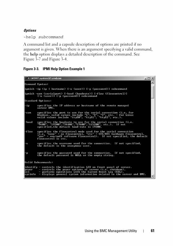
Using the BMC Management Utility 61
Options
-help subcommand
A command list and a capsule description of options are printed if no
argument is given. When there is an argument specifying a valid command,
the help option displays a detailed description of the command. See
Figure 3-7 and Figure 3-4.
Figure 3-3. IPMI Help Option Example 1
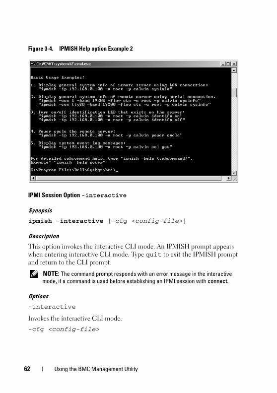
62 Using the BMC Management Utility
Figure 3-4. IPMISH Help option Example 2
IPMI Session Option -interactive
Synopsis
ipmish -interactive [-cfg <config-file>]
Description
This option invokes the interactive CLI mode. An IPMISH prompt appears
when entering interactive CLI mode. Type quit to exit the IPMISH prompt
and return to the CLI prompt.
NOTE: The command prompt responds with an error message in the interactive mode, if a command is used before establishing an IPMI session with connect.
Options
-interactive
Invokes the interactive CLI mode.
-cfg <config-file>
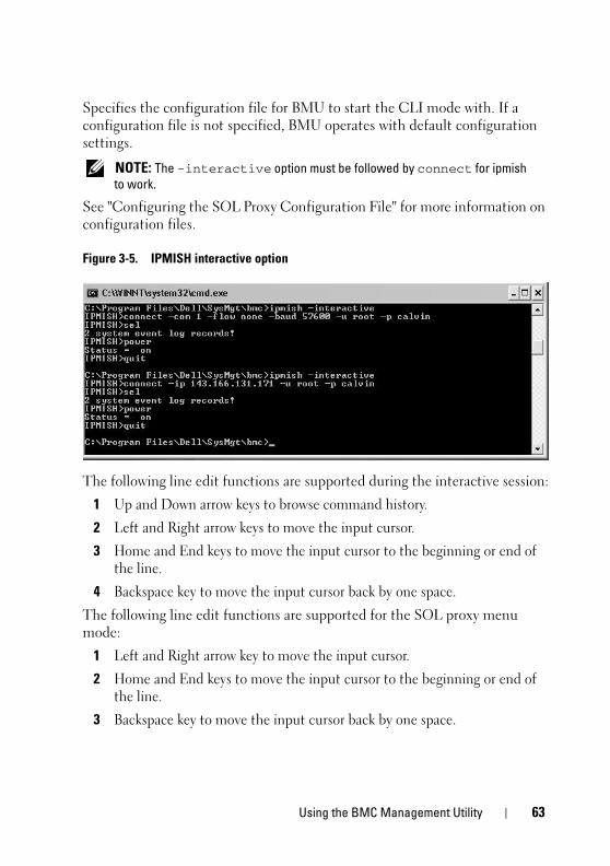
Using the BMC Management Utility 63
Specifies the configuration file for BMU to start the CLI mode with. If a
configuration file is not specified, BMU operates with default configuration
settings.
NOTE: The -interactive option must be followed by connect for ipmish to work.
See "Configuring the SOL Proxy Configuration File" for more information on
configuration files.
Figure 3-5. IPMISH interactive option
The following line edit functions are supported during the interactive session:
1 Up and Down arrow keys to browse command history.
2 Left and Right arrow keys to move the input cursor.
3 Home and End keys to move the input cursor to the beginning or end of
the line.
4 Backspace key to move the input cursor back by one space.
The following line edit functions are supported for the SOL proxy menu
mode:
1 Left and Right arrow key to move the input cursor.
2 Home and End keys to move the input cursor to the beginning or end of
the line.
3 Backspace key to move the input cursor back by one space.
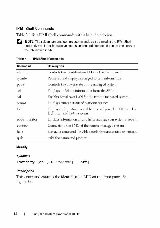
64 Using the BMC Management Utility
IPMI Shell Commands
Table 3-1 lists IPMI Shell commands with a brief description.
NOTE: The sol, sensor, and connect commands can be used in the IPMI Shell interactive and non-interactive modes and the quit command can be used only in the interactive mode.
identify
Synopsis
identify [on [-t seconds] | off]
Description
This command controls the identification LED on the front panel. See
Figure 3-6.
Table 3-1. IPMI Shell Commands
Command Description
identify Controls the identification LED on the front panel.
sysinfo Retrieves and displays managed system information.
power Controls the power state of the managed system.
sel Displays or deletes information from the SEL.
sol Enables Serial-over-LAN for the remote managed system.
sensor Displays current status of platform sensors.
lcd Displays information on and helps configure the LCD panel in
Dell x9xx and xx0x systems.
powermonitor Displays information on and helps manage your system’s power.
connect Connects to the BMC of the remote managed system.
help displays a command list with descriptions and syntax of options.
quit exits the command prompt.
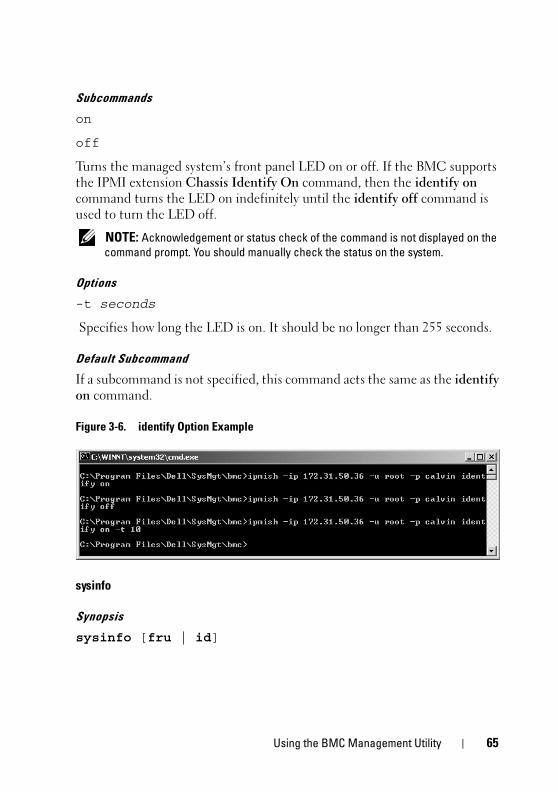
Using the BMC Management Utility 65
Subcommands
on
off
Turns the managed system’s front panel LED on or off. If the BMC supports
the IPMI extension Chassis Identify On command, then the identify on
command turns the LED on indefinitely until the identify off command is
used to turn the LED off.
NOTE: Acknowledgement or status check of the command is not displayed on the command prompt. You should manually check the status on the system.
Options
-t seconds
Specifies how long the LED is on. It should be no longer than 255 seconds.
Default Subcommand
If a subcommand is not specified, this command acts the same as the identify
on command.
Figure 3-6. identify Option Example
sysinfo
Synopsis
sysinfo [fru | id]
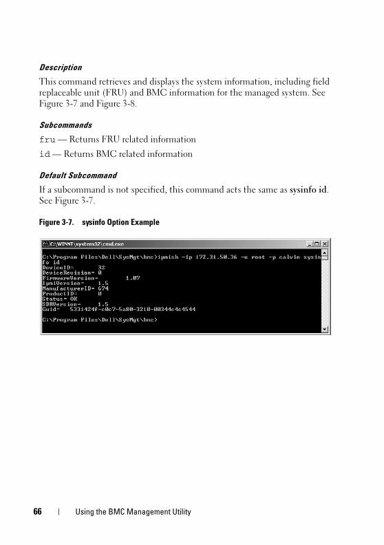
66 Using the BMC Management Utility
Description
This command retrieves and displays the system information, including field
replaceable unit (FRU) and BMC information for the managed system. See
Figure 3-7 and Figure 3-8.
Subcommands
fru — Returns FRU related information
id — Returns BMC related information
Default Subcommand
If a subcommand is not specified, this command acts the same as sysinfo id.
See Figure 3-7.
Figure 3-7. sysinfo Option Example
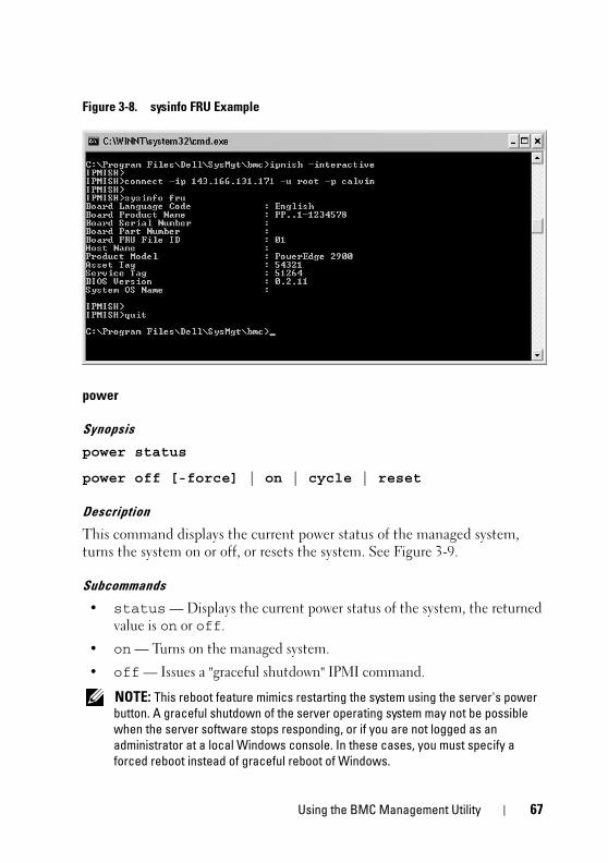
Using the BMC Management Utility 67
Figure 3-8. sysinfo FRU Example
power
Synopsis
power status
power off [-force] | on | cycle | reset
Description
This command displays the current power status of the managed system,
turns the system on or off, or resets the system. See Figure 3-9.
Subcommands
• status — Displays the current power status of the system, the returned
value is on or off.
• on — Turns on the managed system.
• off — Issues a "graceful shutdown" IPMI command.
NOTE: This reboot feature mimics restarting the system using the server's power button. A graceful shutdown of the server operating system may not be possible when the server software stops responding, or if you are not logged as an administrator at a local Windows console. In these cases, you must specify a forced reboot instead of graceful reboot of Windows.

68 Using the BMC Management Utility
• cycle — Turns off the system, pauses, then turns the system back on.
• reset — Pulses the system reset signal, regardless of the power state.
Options
-force
This option simulates pressing and holding the power button for four or more
seconds.
Default Subcommand
If a subcommand is not specified, this command functions the same as
power status.
Figure 3-9. power Option Example
sel
Synopsis
sel status
sel get [ [-begin index1 ] [-end index2 | -max count] ] | [-last n] [-format <oemlist|legacy>]

Using the BMC Management Utility 69
sel clear
Description
This command displays the system event log information, displays the contents
of the event log, and deletes all the event log records. See Figure 3-10.
Subcommands
• status — Displays the total number of system event log records.
• get — Prints all or part of the event log.
• clear — Deletes all the records in the event log.
Options
-begin index1
Specifies the first record to display.
-end index2
Specifies the last record to display.
-max count
Specifies the maximum number of records to display.
If the value of the argument count is bigger than the total number of the
records, the last record displayed will be the last one in the event log.
-last n
Specifies the number of records to be displayed, starting from the last record
and counting backwards.
Default Subcommand
If a subcommand is not specified, this command acts the same as sel status.
Display Format
System event log records are displayed using either a tabular format (legacy)
or a vertical format (oemlist) consistent with the SEL log output found in
other Dell OpenManage products. The default is the oemlist format. The
column headers for the legacy format are: Ordinal Number, Date, Time,
Sensor Number, Sensor Type, and Brief Description. See Figure 3-10 for an
example of oemlist and legacy formatted SEL display.
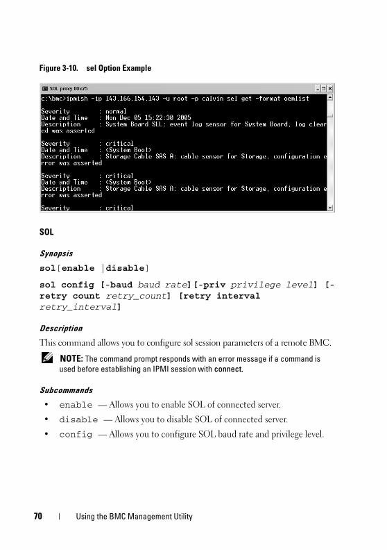
70 Using the BMC Management Utility
Figure 3-10. sel Option Example
SOL
Synopsis
sol[enable |disable]
sol config [-baud baud rate][-priv privilege level] [-retry count retry_count] [retry interval retry_interval]
Description
This command allows you to configure sol session parameters of a remote BMC.
NOTE: The command prompt responds with an error message if a command is used before establishing an IPMI session with connect.
Subcommands
• enable — Allows you to enable SOL of connected server.
• disable — Allows you to disable SOL of connected server.
• config — Allows you to configure SOL baud rate and privilege level.
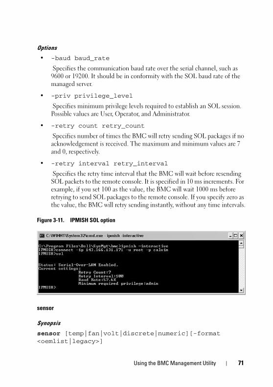
Using the BMC Management Utility 71
Options
• -baud baud_rate
Specifies the communication baud rate over the serial channel, such as
9600 or 19200. It should be in conformity with the SOL baud rate of the
managed server.
• -priv privilege_level
Specifies minimum privilege levels required to establish an SOL session.
Possible values are User, Operator, and Administrator.
• -retry count retry_count
Specifies number of times the BMC will retry sending SOL packages if no
acknowledgement is received. The maximum and minimum values are 7
and 0, respectively.
• -retry interval retry_interval
Specifies the retry time interval that the BMC will wait before resending
SOL packets to the remote console. It is specified in 10 ms increments. For
example, if you set 100 as the value, the BMC will wait 1000 ms before
retrying to send SOL packages to the remote console. If you specify zero as
the value, the BMC will retry sending instantly, without any time intervals.
Figure 3-11. IPMISH SOL option
sensor
Synopsis
sensor [temp|fan|volt|discrete|numeric][-format <oemlist|legacy>]
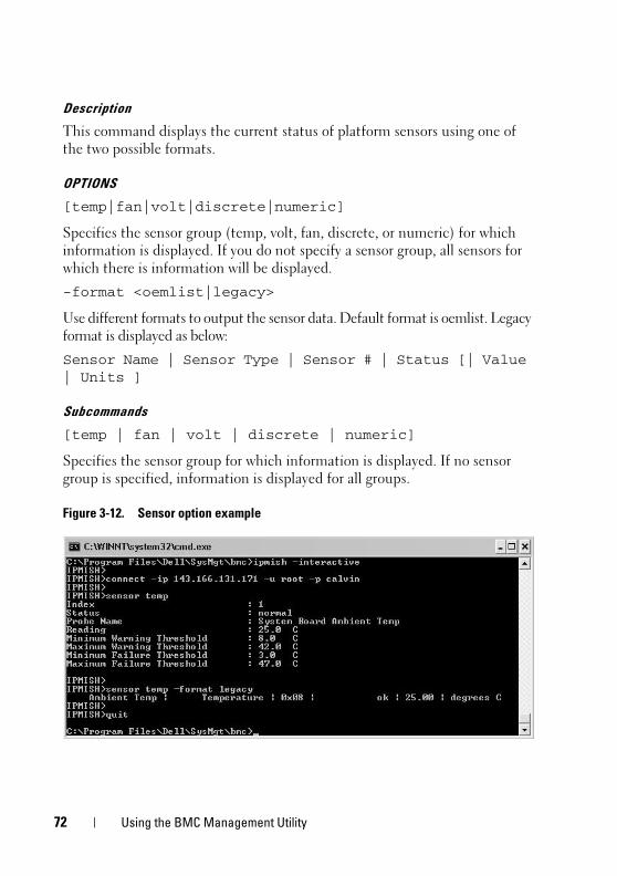
72 Using the BMC Management Utility
Description
This command displays the current status of platform sensors using one of
the two possible formats.
OPTIONS
[temp|fan|volt|discrete|numeric]
Specifies the sensor group (temp, volt, fan, discrete, or numeric) for which
information is displayed. If you do not specify a sensor group, all sensors for
which there is information will be displayed.
-format <oemlist|legacy>
Use different formats to output the sensor data. Default format is oemlist. Legacy
format is displayed as below:
Sensor Name | Sensor Type | Sensor # | Status [| Value | Units ]
Subcommands
[temp | fan | volt | discrete | numeric]
Specifies the sensor group for which information is displayed. If no sensor
group is specified, information is displayed for all groups.
Figure 3-12. Sensor option example
Using the BMC Management Utility 73
connect
Synopsis
connect -ip bmc-ip-address | bmc-host-name [-u username] [-p password] [-k IPMI encryption key value]
connect -com bmc_ip_address | bmc_hostname -u username -p password
[-k KG value] <command>
Description
This command establishes an IPMI connection with the remote server in the
interactive mode to enable the user to perform server management activities.
The command remains active until the user quits the command prompt or
uses the command again to connect to a different server.
Options
-ip bmc-ip-address|bmc_hostname
Specifies the out-of-band IP address or hostname of the remote managed
system.
-u username
Specifies the username to connect to the remote system.
-p password
Specifies the password to be used to connect to the remote managed system.
-k IPMI encryption key value
Specifies the KG value in Hex format. The IPMI encryption key is a public
key used to generate an encryption key for use between firmware and
application. It is differentiated from a password, which is not public and is
used to access the firmware. The maximum value is 20 ASCII hex pairs with
no spaces between the pairs.
NOTE: Even number of hexadecimal characters is valid and odd number of hexadecimal characters is invalid. For example, 123456AB67 is valid, and 123 is invalid. Enter 00, 0000, etc. to disable encryption.
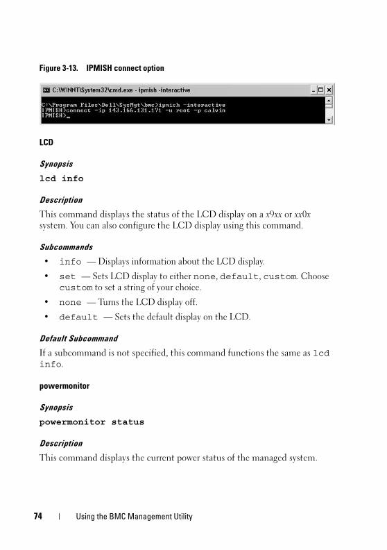
74 Using the BMC Management Utility
Figure 3-13. IPMISH connect option
LCD
Synopsis
lcd info
Description
This command displays the status of the LCD display on a x9xx or xx0x
system. You can also configure the LCD display using this command.
Subcommands
• info — Displays information about the LCD display.
• set — Sets LCD display to either none, default, custom. Choose
custom to set a string of your choice.
• none — Turns the LCD display off.
• default — Sets the default display on the LCD.
Default Subcommand
If a subcommand is not specified, this command functions the same as lcd info.
powermonitor
Synopsis
powermonitor status
Description
This command displays the current power status of the managed system.

Using the BMC Management Utility 75
Subcommands
• status — Displays the current power status of the system.
The returned values denote energy consumption, peak power (in Watts),
and peak amperage.
• clear peakpower — Deletes the peak power value.
• clear cumulativepower — Deletes the cumulative power values.
Default Subcommand
If a subcommand is not specified, this command functions the same as power
status.
quit
Synopsis
quit
Description
This command exits the IPMI Shell interactive mode and returns to the
command mode.
help
Synopsis
help [command]
Description
This command lists commands and capsule descriptions with syntax for each
command.
Argument
command
Specifies the command for which detailed description is required.
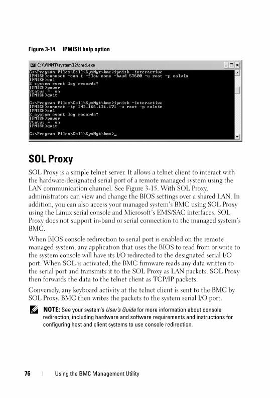
76 Using the BMC Management Utility
Figure 3-14. IPMISH help option
SOL ProxySOL Proxy is a simple telnet server. It allows a telnet client to interact with
the hardware-designated serial port of a remote managed system using the
LAN communication channel. See Figure 3-15. With SOL Proxy,
administrators can view and change the BIOS settings over a shared LAN. In
addition, you can also access your managed system’s BMC using SOL Proxy
using the Linux serial console and Microsoft’s EMS/SAC interfaces. SOL
Proxy does not support in-band or serial connection to the managed system’s
BMC.
When BIOS console redirection to serial port is enabled on the remote
managed system, any application that uses the BIOS to read from or write to
the system console will have its I/O redirected to the designated serial I/O
port. When SOL is activated, the BMC firmware reads any data written to
the serial port and transmits it to the SOL Proxy as LAN packets. SOL Proxy
then forwards the data to the telnet client as TCP/IP packets.
Conversely, any keyboard activity at the telnet client is sent to the BMC by
SOL Proxy. BMC then writes the packets to the system serial I/O port.
NOTE: See your system’s User’s Guide for more information about console redirection, including hardware and software requirements and instructions for configuring host and client systems to use console redirection.
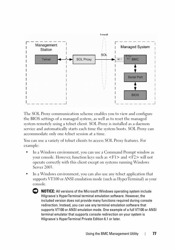
Using the BMC Management Utility 77
The SOL Proxy communication scheme enables you to view and configure
the BIOS settings of a managed system, as well as to reset the managed
system remotely using a telnet client. SOL Proxy is installed as a daemon
service and automatically starts each time the system boots. SOL Proxy can
accommodate only one telnet session at a time.
You can use a variety of telnet clients to access SOL Proxy features. For
example:
• In a Windows environment, you can use a Command Prompt window as
your console. However, function keys such as <F1> and <F2> will not
operate correctly with this client except on systems running Windows
Server 2003.
• In a Windows environment, you can also use any telnet application that
supports VT100 or ANSI emulation mode (such as HyperTerminal) as your
console.
NOTICE: All versions of the Microsoft Windows operating system include Hilgraeve's HyperTerminal terminal emulation software. However, the included version does not provide many functions required during console redirection. Instead, you can use any terminal emulation software that supports VT100 or ANSI emulation mode. One example of a full VT100 or ANSI terminal emulator that supports console redirection on your system is Hilgraeve's HyperTerminal Private Edition 6.1 or later.
78 Using the BMC Management Utility
NOTE: When using HyperTerminal, you must deselect the Wrap lines that exceed terminal width check box to avoid console redirected data that may appear to be corrupted or garbled. To deselect this feature, click File! Properties! Settings! ASCII Setup…! Wrap lines that exceed terminal width.
NOTE: See your system’s User’s Guide for more information about console redirection, including hardware and software requirements and instructions for configuring host and client systems to use console redirection.
• In a Linux environment, you can use a shell such as csh or ksh as your
console, or you can use any telnet application supporting VT100 or ANSI
emulation mode.
NOTE: Telnet settings must be consistent with the settings on the managed system. For example, the baud rates and terminal modes should match.
You can also send the terminal break function while in console redirection.
The use of this functionality requires that the specific terminal program in
use has the ability to send the break function. For example, you can send the
break signal through the Linux telnet modules by typing:
Ctrl+]send brk<Enter>
The Linux SysRq function is one example of an advanced debugging feature
that is enabled by use of the break function. See the "BIOS Configuration"
section on how to use this feature. See the "Serial Console redirection With
SOL Proxy" section for more information on the SysRq feature.
To enable BIOS console redirection for use with SOLProxy:
• Configure the Console redirection attribute to On with Console
Redirection via COM2 for Dell x9xx and xx0x systems. This option is
available under the Serial Communication submenu in BIOS setup.
• Configure the Console Redirection attribute to Serial Port1 for
PowerEdge x8xx systems. This option is available under the Console
Redirection menu in BIOS Setup. Set Serial Port 1 to BMC NIC. This
option is available under the Integrated Devices menu in BIOS Setup.
Using SOL Proxy
Depending on the console you use, there are different steps for accessing SOL
Proxy. Throughout this section, the management station where the SOL
Proxy is running is referred to as the SOL Proxy Server.

Using the BMC Management Utility 79
Initiating the SOL Proxy session using the Windows Command Prompt:
To connect and use SOL Proxy:
1 Open a Command Prompt window on your management station.
2 Enter the telnet command in the command-line and provide the
IP address of the SOL Proxy server and the port number that you specified
in the SOL Proxy installation (the default value is 623). For example:
telnet 192.168.1.24 623
NOTE: The IP address and port number you provide should conform to the ones defined in the SOL Proxy configuration file. For more details, see “Configuring the SOL Proxy Configuration File.”
3 If you are prompted for a username, provide the operating system login
credentials of the system running the service: DSM_BMU_SOL_Proxy.
4 Provide a password when prompted. SOL Proxy will use this combination
of operating system username and password to authenticate you on the
SOL Proxy Server. The specific authentication scheme will depend on the
operating system configuration for the SOL Proxy Server. However, if
localhost or an IP address of 127.0.0.1 is used, it is assumed that the user
has login privileges to the current host, and is not prompted for a
username and password.
5 After authentication, a login successful message and the SOL Proxy main
menu prompt appear. You are ready to use SOL Proxy. By default, you will
be logged in the menu mode. See "SOL Proxy Main Menu" for further
instructions.
The following line edit functions are supported during the SOLProxy session:
1 Up- and down-arrow keys to browse command history.
2 Left- and right-arrow keys to move the input cursor.
80 Using the BMC Management Utility
Using a Linux Shell
To connect and use SOL Proxy:
1 Open a Linux shell on your management station.
2 Enter the telnet command and provide the IP address of the SOL Proxy
Server and the port number you specified in SOL Proxy installation. For
example:
telnet 192.168.1.24 623
NOTE: The IP address and port number you provide should conform to the ones defined in the SOL Proxy configuration file. For more details, see “Configuring the SOL Proxy Configuration File.”
3 If you are prompted for a username, provide the operating system login
credentials of SOL Proxy Server.
4 Provide a password when prompted. SOL Proxy will use this combination
of operating system username and password to authenticate you on the
SOL Proxy Server. The specific authentication scheme will depend on the
operating system configuration for the SOL Proxy Server. However, if
localhost or an IP address of 127.0.0.1 is used, it is assumed that the user
has login privileges to the current host, and is not prompted for a
username and password.
5 After authentication, a login successful message and the SOL Proxy main
menu prompt appear. You are ready to use SOL Proxy. See "SOL Proxy
Main Menu" for further instructions.
SOL Proxy Main Menu
After the telnet connection with SOL Proxy is successfully established, you
are presented with the following choices. See Figure 3-15.
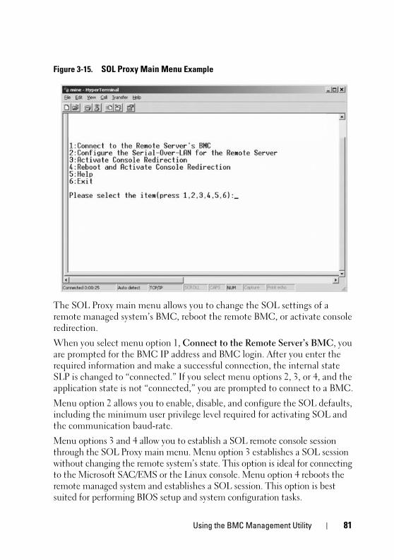
Using the BMC Management Utility 81
Figure 3-15. SOL Proxy Main Menu Example
The SOL Proxy main menu allows you to change the SOL settings of a
remote managed system’s BMC, reboot the remote BMC, or activate console
redirection.
When you select menu option 1, Connect to the Remote Server’s BMC, you
are prompted for the BMC IP address and BMC login. After you enter the
required information and make a successful connection, the internal state
SLP is changed to “connected.” If you select menu options 2, 3, or 4, and the
application state is not “connected,” you are prompted to connect to a BMC.
Menu option 2 allows you to enable, disable, and configure the SOL defaults,
including the minimum user privilege level required for activating SOL and
the communication baud-rate.
Menu options 3 and 4 allow you to establish a SOL remote console session
through the SOL Proxy main menu. Menu option 3 establishes a SOL session
without changing the remote system’s state. This option is ideal for connecting
to the Microsoft SAC/EMS or the Linux console. Menu option 4 reboots the
remote managed system and establishes a SOL session. This option is best
suited for performing BIOS setup and system configuration tasks.
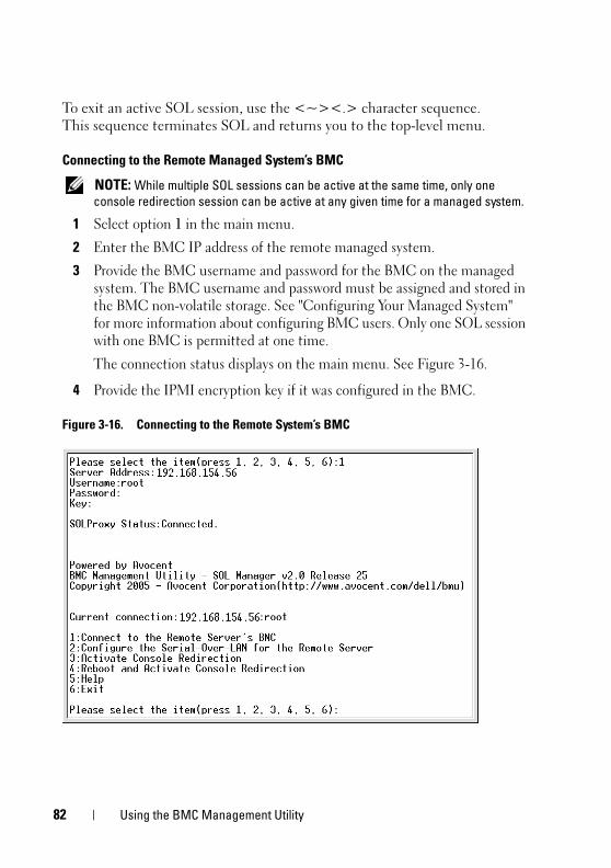
82 Using the BMC Management Utility
To exit an active SOL session, use the <~><.> character sequence.
This sequence terminates SOL and returns you to the top-level menu.
Connecting to the Remote Managed System’s BMC
NOTE: While multiple SOL sessions can be active at the same time, only one console redirection session can be active at any given time for a managed system.
1 Select option 1 in the main menu.
2 Enter the BMC IP address of the remote managed system.
3 Provide the BMC username and password for the BMC on the managed
system. The BMC username and password must be assigned and stored in
the BMC non-volatile storage. See "Configuring Your Managed System"
for more information about configuring BMC users. Only one SOL session
with one BMC is permitted at one time.
The connection status displays on the main menu. See Figure 3-16.
4 Provide the IPMI encryption key if it was configured in the BMC.
Figure 3-16. Connecting to the Remote System’s BMC

Using the BMC Management Utility 83
Configuring the SOL for the Remote Managed System
Select option 2 in the main menu.
NOTE: You must be connected to the managed system’s BMC before you can configure the SOL features. If SOL Proxy is not yet connected to the managed system’s BMC, you are prompted for an IP address, a username/password combination, and an IPMI encryption key. The IPMI encryption key value will be ignored if no key was set at the BMC on the target server. See "Connecting to the Remote Managed System’s BMC" for more information.
The SOL configuration menu appears. According to the current SOL status,
the content of the SOL configuration menu varies:
• If SOL is already enabled, the current settings are displayed and you are
presented with three choices. See Figure 3-17.
Figure 3-17. Configuring the Serial-Over-LAN for the Remote System, Example 1
• If SOL is currently disabled, the options shown in Figure 3-18 are
displayed. Type Y to enable SOL or N to keep SOL disabled. See
Figure 3-18.
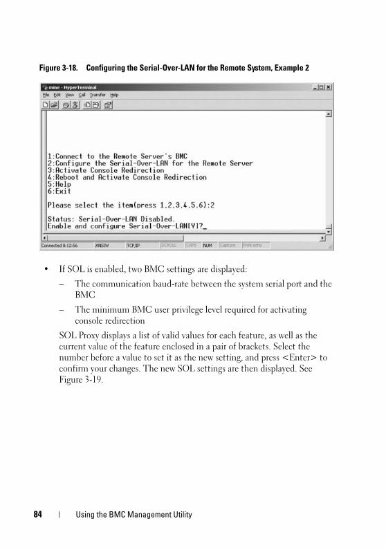
84 Using the BMC Management Utility
Figure 3-18. Configuring the Serial-Over-LAN for the Remote System, Example 2
• If SOL is enabled, two BMC settings are displayed:
– The communication baud-rate between the system serial port and the
BMC
– The minimum BMC user privilege level required for activating
console redirection
SOL Proxy displays a list of valid values for each feature, as well as the
current value of the feature enclosed in a pair of brackets. Select the
number before a value to set it as the new setting, and press <Enter> to
confirm your changes. The new SOL settings are then displayed. See
Figure 3-19.
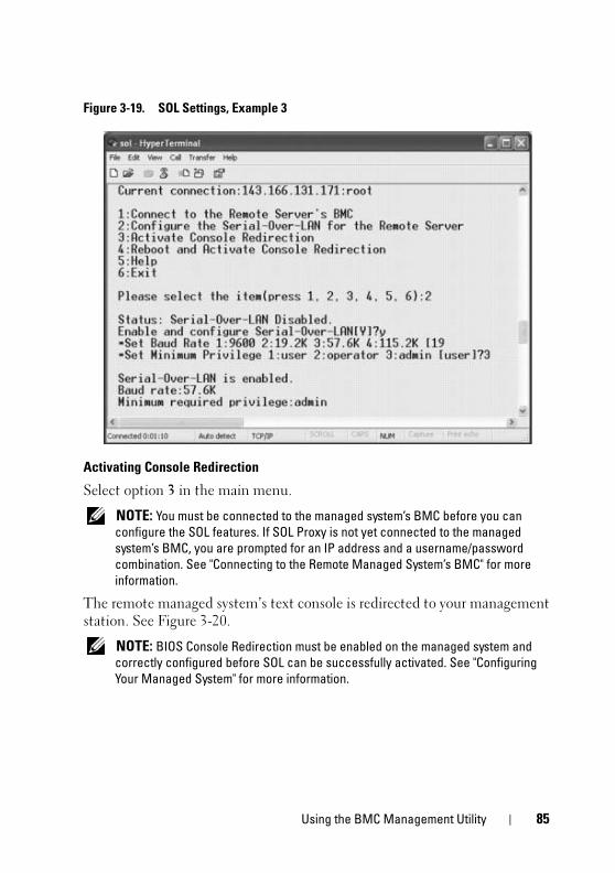
Using the BMC Management Utility 85
Figure 3-19. SOL Settings, Example 3
Activating Console Redirection
Select option 3 in the main menu.
NOTE: You must be connected to the managed system’s BMC before you can configure the SOL features. If SOL Proxy is not yet connected to the managed system’s BMC, you are prompted for an IP address and a username/password combination. See "Connecting to the Remote Managed System’s BMC" for more information.
The remote managed system’s text console is redirected to your management
station. See Figure 3-20.
NOTE: BIOS Console Redirection must be enabled on the managed system and correctly configured before SOL can be successfully activated. See "Configuring Your Managed System" for more information.
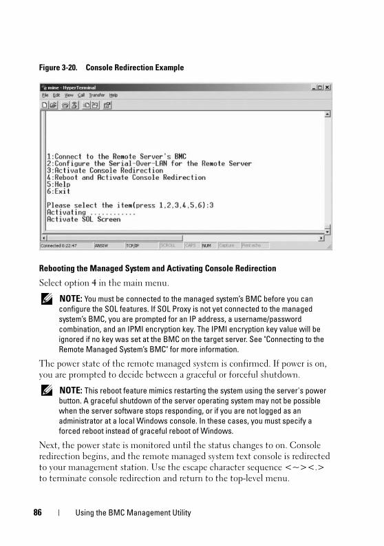
86 Using the BMC Management Utility
Figure 3-20. Console Redirection Example
Rebooting the Managed System and Activating Console Redirection
Select option 4 in the main menu.
NOTE: You must be connected to the managed system’s BMC before you can configure the SOL features. If SOL Proxy is not yet connected to the managed system’s BMC, you are prompted for an IP address, a username/password combination, and an IPMI encryption key. The IPMI encryption key value will be ignored if no key was set at the BMC on the target server. See "Connecting to the Remote Managed System’s BMC" for more information.
The power state of the remote managed system is confirmed. If power is on,
you are prompted to decide between a graceful or forceful shutdown.
NOTE: This reboot feature mimics restarting the system using the server's power button. A graceful shutdown of the server operating system may not be possible when the server software stops responding, or if you are not logged as an administrator at a local Windows console. In these cases, you must specify a forced reboot instead of graceful reboot of Windows.
Next, the power state is monitored until the status changes to on. Console
redirection begins, and the remote managed system text console is redirected
to your management station. Use the escape character sequence <~><.>
to terminate console redirection and return to the top-level menu.
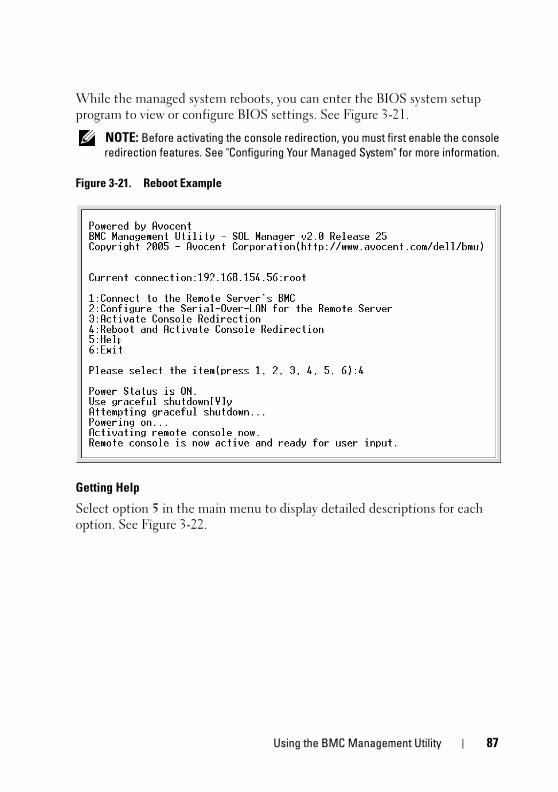
Using the BMC Management Utility 87
While the managed system reboots, you can enter the BIOS system setup
program to view or configure BIOS settings. See Figure 3-21.
NOTE: Before activating the console redirection, you must first enable the console redirection features. See "Configuring Your Managed System" for more information.
Figure 3-21. Reboot Example
Getting Help
Select option 5 in the main menu to display detailed descriptions for each
option. See Figure 3-22.
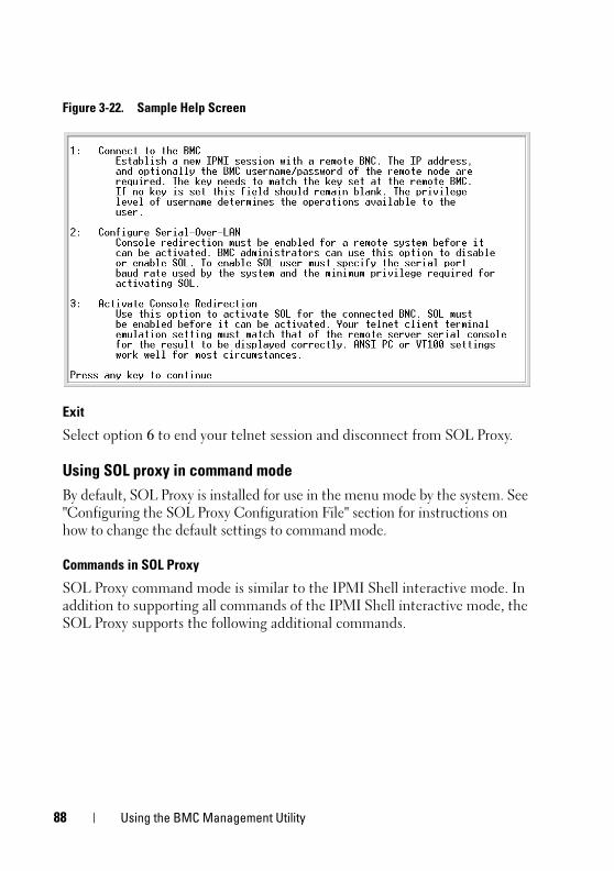
88 Using the BMC Management Utility
Figure 3-22. Sample Help Screen
Exit
Select option 6 to end your telnet session and disconnect from SOL Proxy.
Using SOL proxy in command mode
By default, SOL Proxy is installed for use in the menu mode by the system. See
"Configuring the SOL Proxy Configuration File" section for instructions on
how to change the default settings to command mode.
Commands in SOL Proxy
SOL Proxy command mode is similar to the IPMI Shell interactive mode. In
addition to supporting all commands of the IPMI Shell interactive mode, the
SOL Proxy supports the following additional commands.
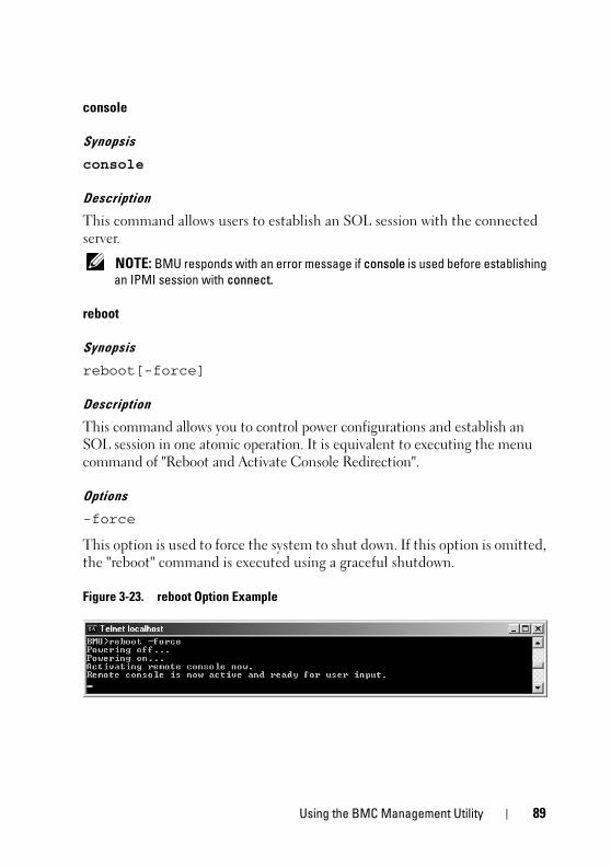
Using the BMC Management Utility 89
console
Synopsis
console
Description
This command allows users to establish an SOL session with the connected
server.
NOTE: BMU responds with an error message if console is used before establishing an IPMI session with connect.
reboot
Synopsis
reboot[-force]
Description
This command allows you to control power configurations and establish an
SOL session in one atomic operation. It is equivalent to executing the menu
command of "Reboot and Activate Console Redirection".
Options
-force
This option is used to force the system to shut down. If this option is omitted,
the "reboot" command is executed using a graceful shutdown.
Figure 3-23. reboot Option Example

90 Using the BMC Management Utility
Configuring the SOL Proxy Configuration FileCertain parameters, for IPMI Shell and SOL Proxy, must be correctly
configured in the SOL Proxy Configuration file, - SOLProxy.cfg, which is
located in the default installation BMC directory.
The parameters and their descriptions are as follows:
Comments
Any line starting with a “#” is treated as a comment. For example:
#The file is an example.
IP Address
Specifies the specific IP address used to connect to SOL Proxy. This item
defines what kind of connection can be accepted to establish a SOL Proxy
telnet session. There are three possible values:
• INADDR_ANY — SOL proxy listens for input on any interface on the server.
• 127.0.0.1 — SOL proxy listens for input on the localhost only.
• IP address — SOL proxy listens for input on this IP address only.
For example:
ip=INADDR_ANY
Port Binding
Specifies the port at which the SOL Proxy listens for incoming connections.
By default, the port is set to 623 and can be modified by the user.
This item defines the port when you telnet SOL Proxy. If this item is absent,
623 is set as the default port. For example:
port=623
Session Timeout
Specifies the time in minutes before the SOL Proxy session times out.
If there is no keyboard activity for the specified timeout period, the telnet
session and the SOL session will be closed. The timeout value is specified in
minutes and can be changed during SOL Proxy installation. For example:
session_timeout=30
Using the BMC Management Utility 91
Power-off Timeout
Specifies the time in seconds before the SOL Proxy gives up polling for the
managed system's power status. If the SOL Proxy issues the power off
command and the system does not power off within the specified interval, the
SOL Proxy returns with a message, indicating that the SOL Proxy was unable
to power off the system due to the timeout interval.
NOTE: When Reboot and Activate Console Redirection is selected and power for the remote managed system is on, a power off IPMI command is issued. The power status is then continually monitored until the power status reports “off.” If power status remains “on” longer than this timeout period, Reboot and Activate Console Redirection reports an error and returns to the top-level menu. This timeout value is specified in seconds and can be changed during SOL Proxy installation.
For example:
power_off_timeout=60
Retry Interval
Specifies the period of time in seconds that the BMC waits before it tries to
resend a packet. The retry_interval unit is half a second. Therefore, a value of
2 means that the software waits one second for the BMC to respond before it
tries to resend the packet, a value of 4 means that it waits two seconds, and so
on. For example:
retry_interval=2
Retry Count
Specifies the maximum number of times that the software tries to resend a
packet if it does not receive a response from the BMC. Before each retry, the
software waits for the interval specified by the retry_interval parameter. For
example:
retry_count=10
User Interface
Specifies the default settings for SOL Proxy startup. The user can edit and set
this comment in the command or menu mode. For example:
user_interface=menu
92 Using the BMC Management Utility
Sol Loss Silent
Specifies system behavior when one or more SOL packets are lost. The
possible values are 0 and 1. If it is set to 0 or is absent, the system will print an
error message on the screen each time an SOL packet is lost. If it is set to 1,
the system will not print error messages for loss of SOL packets. For example:
sol_loss_silent=0 or 1
Sol Loss Threshold
Specifies number of SOL packets that can be lost before SOL deactivation.
The default value is 0, which means that the system will deactivate SOL, if
any SOL packets are lost. For example,
sol_loss_silent_threshold=0
Sdr Cache
Specifies whether the system probe information is saved. This information
enhances speed of providing sensor and System Event Log (SEL) data. The
possible values are on and off. Default value is on. For example,
sdr_cache=on
Sdrcache Path
Specifies path where the system probe information is saved. Default location
is the installed BMC directory on your hard drive. For example,
sdrcache_path=<specified path directory>
Max Session
Specifies the maximum number of concurrent SOL sessions possible.
This default value is 1; any value less than 1 will be ignored or treated as 1.
You cannot set more than 20 sessions. For example,
max_session=2
Logpath
Specifies the path for storing the log files. Two log files, solproxy.log and
solproxyipmi.log, are created at the specified path. For example,
logpath=<specified location for log file>
Using the BMC Management Utility 93
debug
Specifies if the debug data will be logged. The default is off.
debug=off
IPMItoolIPMItool is a CLI utility that helps in configuring and managing devices using the
IPMI version 1.5 and later protocol. IPMItool supports out-of-band (OOB) access
(over a LAN or through the serial port) to a single system at a time. However,
multiple IPMItool sessions can run simultaneously on the same managed system.
IPMItool allows a user with user-level BMC privileges to:
• Display the current power status.
• Display the 16-byte system GUID of the managed system.
• Display information from the system’s FRU.
• Display the BMC firmware information.
• Display summary information about the system event log.
• Display logged events.
• Display current status of platform sensors.
• Enable or disable SOL.
NOTE: See the IPMItool man page available on the World Wide Web for a comprehensive list of features.
NOTE: While running ipmitool inband on Linux, if the OpenIPMI driver is not running by default, it may cause commands to fail. To start the OpenIPMI drivers, use the command service ipmi start. To set the system to start the driver automatically during boot, use chkconfig ipmi on.
In addition to the operations that can be performed by a user with user-level
BMC user privileges, IPMItool allows a user with operator-level and
administrator-level BMC user privileges to:
• Power on, reset, or power cycle a managed system.
• Simulate a hard power off on a managed system (forcing the system to
turn off without shutting down the operating system).
• Clear the system event log (SEL).
• Turn the blinking system identification LED on or off.
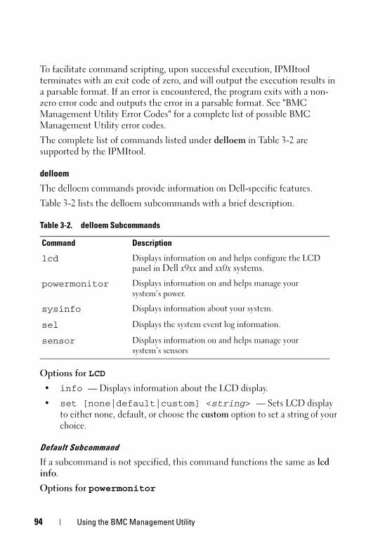
94 Using the BMC Management Utility
To facilitate command scripting, upon successful execution, IPMItool
terminates with an exit code of zero, and will output the execution results in
a parsable format. If an error is encountered, the program exits with a non-
zero error code and outputs the error in a parsable format. See "BMC
Management Utility Error Codes" for a complete list of possible BMC
Management Utility error codes.
The complete list of commands listed under delloem in Table 3-2 are
supported by the IPMItool.
delloem
The delloem commands provide information on Dell-specific features.
Table 3-2 lists the delloem subcommands with a brief description.
Options for LCD
• info — Displays information about the LCD display.
• set [none|default|custom] <string> — Sets LCD display
to either none, default, or choose the custom option to set a string of your
choice.
Default Subcommand
If a subcommand is not specified, this command functions the same as lcd
info.
Options for powermonitor
Table 3-2. delloem Subcommands
Command Description
lcd Displays information on and helps configure the LCD
panel in Dell x9xx and xx0x systems.
powermonitor Displays information on and helps manage your
system’s power.
sysinfo Displays information about your system.
sel Displays the system event log information.
sensor Displays information on and helps manage your
system’s sensors
Using the BMC Management Utility 95
status—Displays the current power status of the system. The returned
values denote energy consumption, peak power (in Watts), and peak
amperage.
clear peakpower—Resets the peak power value.
clear cumulativepower—Resets the cumulative power values.
Default Subcommand
If a subcommand is not specified, this command functions the same as
powermonitor status.
Options for sysinfo
This command returns both FRU and BMC related information for your
system.
Options for sel
• info — Displays information about and the contents of the system
event log.
• clear — Deletes all records in the event log.
• list — Displays all contents of the event log.
• <count>|first <count> — Displays the first <count> (oldest)
entries in the SEL. If the count is zero, all entries are displayed.
• last <count> — Displays the last <count> (most recent) entries in
the SEL. If the count is zero, all entries are displayed.
• time — Displays the most recent entries in the SEL. If the count is zero,
all entries are displayed. You can use the get command to display the
system event log’s current time. The set <time string> option
allows you to set the system event log’s time. Future event log entries will
use the time set by this command. <time string> is in the form
<MM/DD/YYYY HH:MM:SS>.
NOTE: Hours are in 24-hour form. It is recommended that the event log be cleared before setting the time.
NOTE: Time values between delloem sel time and sel time differ but the delloem sel time command returns the correct value for Dell systems.
96 Using the BMC Management Utility
Default Subcommand
If a subcommand is not specified, this command functions the same as sel
info.
Options for sensor
• list — Displays the complete list of sensors and thresholds in a wide
table format.
• get <id> ... [<id>] — Displays information for sensors specified
by ID number.
• thresh <id> <threshold> <setting> — Allows you to set a
particular sensor threshold value. The sensor is specified by name. Valid
thresholds are:
• unr — Upper Non-Recoverable
• ucr — Upper Critical
• unc — Upper Non-Critical
• lnc — Lower Non-Critical
• lcr — Lower Critical
• lnr — Lower Non-Recoverable
Default Subcommand
If a subcommand is not specified, this command acts the same as sensor list.
IPMItool Command for Dynamic Entry on the DNS Server When DRAC is Not Present
To create a dynamic entry on the DNS server when DRAC is not present, use
the following command:
ipmitool raw 0x18 0x58 0xe4 0x15
NOTE: You must enter a 21-byte hexadecimal number (a 8-byte input for the PowerEdge 1435SC) for the DHCP name. If the DHCP name is less than 21 bytes (8 bytes for PowerEdge SC1435), pad the end with zeroes.
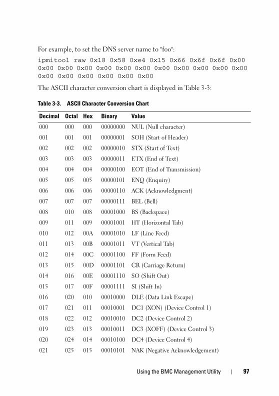
Using the BMC Management Utility 97
For example, to set the DNS server name to "foo":
ipmitool raw 0x18 0x58 0xe4 0x15 0x66 0x6f 0x6f 0x00 0x00 0x00 0x00 0x00 0x00 0x00 0x00 0x00 0x00 0x00 0x00 0x00 0x00 0x00 0x00 0x00 0x00
The ASCII character conversion chart is displayed in Table 3-3:
Table 3-3. ASCII Character Conversion Chart
Decimal Octal Hex Binary Value
000 000 000 00000000 NUL (Null character)
001 001 001 00000001 SOH (Start of Header)
002 002 002 00000010 STX (Start of Text)
003 003 003 00000011 ETX (End of Text)
004 004 004 00000100 EOT (End of Transmission)
005 005 005 00000101 ENQ (Enquiry)
006 006 006 00000110 ACK (Acknowledgment)
007 007 007 00000111 BEL (Bell)
008 010 008 00001000 BS (Backspace)
009 011 009 00001001 HT (Horizontal Tab)
010 012 00A 00001010 LF (Line Feed)
011 013 00B 00001011 VT (Vertical Tab)
012 014 00C 00001100 FF (Form Feed)
013 015 00D 00001101 CR (Carriage Return)
014 016 00E 00001110 SO (Shift Out)
015 017 00F 00001111 SI (Shift In)
016 020 010 00010000 DLE (Data Link Escape)
017 021 011 00010001 DC1 (XON) (Device Control 1)
018 022 012 00010010 DC2 (Device Control 2)
019 023 013 00010011 DC3 (XOFF) (Device Control 3)
020 024 014 00010100 DC4 (Device Control 4)
021 025 015 00010101 NAK (Negative Acknowledgement)

98 Using the BMC Management Utility
022 026 016 00010110 SYN (Synchronous Idle)
023 027 017 00010111 ETB (End of Transmission Block)
024 030 018 00011000 CAN (Cancel)
025 031 019 00011001 EM (End of Medium)
026 032 01A 00011010 SUB (Substitute)
027 033 01B 00011011 ESC (Escape)
028 034 01C 00011100 FS (File Separator)
029 035 01D 00011101 GS (Group Separator)
030 036 01E 00011110 RS (Request to Send) (Record Separator)
031 037 01F 00011111 US (Unit Separator)
032 040 020 00100000 SP (Space)
033 041 021 00100001 ! (Exclamation Mark)
034 042 022 00100010 " (Double Quote)
035 043 023 00100011 # (Number Sign)
036 044 024 00100100 $ (Dollar Sign)
037 045 025 00100101 % (Percent)
038 046 026 00100110 & (Ampersand)
039 047 027 00100111 ' (Single Quote)
040 050 028 00101000 ( (Left/Opening Parenthesis)
041 051 029 00101001 ) (Right/Closing Parenthesis)
042 052 02A 00101010 * (Asterisk)
043 053 02B 00101011 + (Plus)
044 054 02C 00101100 , (Comma)
045 055 02D 00101101 - (Minus or Dash)
046 056 02E 00101110 . (Dot)
047 057 02F 00101111 / (Forward Slash)
048 060 030 00110000 0
Table 3-3. ASCII Character Conversion Chart (continued)
Decimal Octal Hex Binary Value
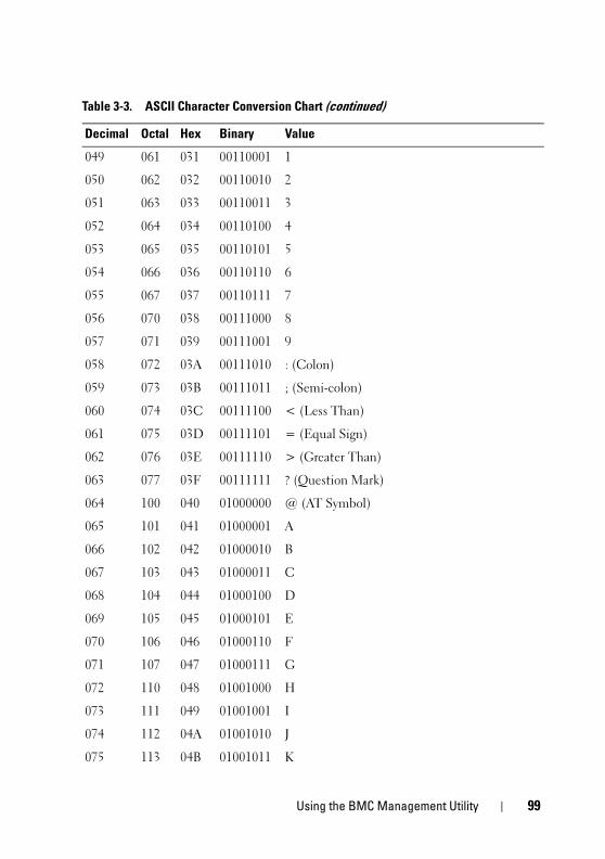
Using the BMC Management Utility 99
049 061 031 00110001 1
050 062 032 00110010 2
051 063 033 00110011 3
052 064 034 00110100 4
053 065 035 00110101 5
054 066 036 00110110 6
055 067 037 00110111 7
056 070 038 00111000 8
057 071 039 00111001 9
058 072 03A 00111010 : (Colon)
059 073 03B 00111011 ; (Semi-colon)
060 074 03C 00111100 < (Less Than)
061 075 03D 00111101 = (Equal Sign)
062 076 03E 00111110 > (Greater Than)
063 077 03F 00111111 ? (Question Mark)
064 100 040 01000000 @ (AT Symbol)
065 101 041 01000001 A
066 102 042 01000010 B
067 103 043 01000011 C
068 104 044 01000100 D
069 105 045 01000101 E
070 106 046 01000110 F
071 107 047 01000111 G
072 110 048 01001000 H
073 111 049 01001001 I
074 112 04A 01001010 J
075 113 04B 01001011 K
Table 3-3. ASCII Character Conversion Chart (continued)
Decimal Octal Hex Binary Value

100 Using the BMC Management Utility
076 114 04C 01001100 L
077 115 04D 01001101 M
078 116 04E 01001110 N
079 117 04F 01001111 O
080 120 050 01010000 P
081 121 051 01010001 Q
082 122 052 01010010 R
083 123 053 01010011 S
084 124 054 01010100 T
085 125 055 01010101 U
086 126 056 01010110 V
087 127 057 01010111 W
088 130 058 01011000 X
089 131 059 01011001 Y
090 132 05A 01011010 Z
091 133 05B 01011011 [ (Left/Opening Bracket)
092 134 05C 01011100 \ (Back Slash)
093 135 05D 01011101 ] (Right/Closing Bracket)
094 136 05E 01011110 ^ (Caret/Circumflex)
095 137 05F 01011111 _ (Underscore)
096 140 060 01100000 `
097 141 061 01100001 a
098 142 062 01100010 b
099 143 063 01100011 c
100 144 064 01100100 d
101 145 065 01100101 e
102 146 066 01100110 f
Table 3-3. ASCII Character Conversion Chart (continued)
Decimal Octal Hex Binary Value
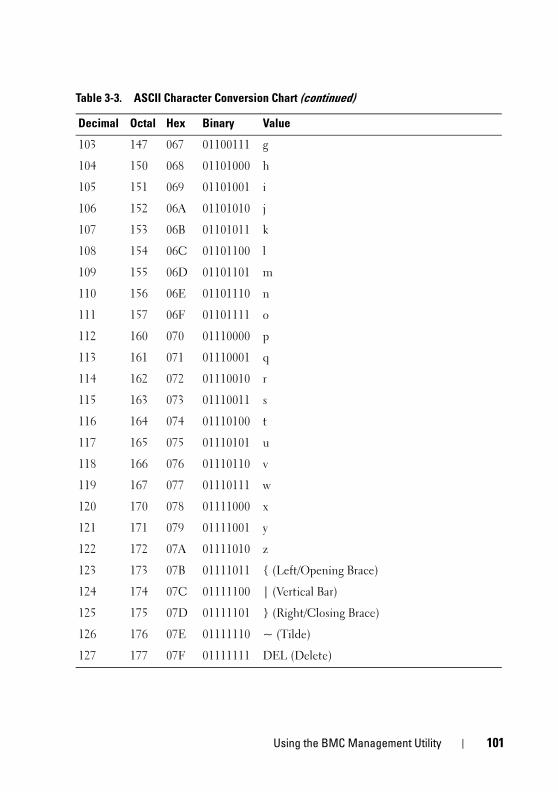
Using the BMC Management Utility 101
103 147 067 01100111 g
104 150 068 01101000 h
105 151 069 01101001 i
106 152 06A 01101010 j
107 153 06B 01101011 k
108 154 06C 01101100 l
109 155 06D 01101101 m
110 156 06E 01101110 n
111 157 06F 01101111 o
112 160 070 01110000 p
113 161 071 01110001 q
114 162 072 01110010 r
115 163 073 01110011 s
116 164 074 01110100 t
117 165 075 01110101 u
118 166 076 01110110 v
119 167 077 01110111 w
120 170 078 01111000 x
121 171 079 01111001 y
122 172 07A 01111010 z
123 173 07B 01111011 { (Left/Opening Brace)
124 174 07C 01111100 | (Vertical Bar)
125 175 07D 01111101 } (Right/Closing Brace)
126 176 07E 01111110 ~ (Tilde)
127 177 07F 01111111 DEL (Delete)
Table 3-3. ASCII Character Conversion Chart (continued)
Decimal Octal Hex Binary Value

102 Using the BMC Management Utility
Known Issues and Frequently Asked Questions 103
Known Issues and Frequently Asked QuestionsThis section discusses known issues with using the BMC Management Utility,
along with frequently asked questions.
Known Issues
General Issues
• You must assign a valid BMC user name and password before you can
connect to your system's BMC using the BMC Management Utility. If you
do not explicitly provide a valid BMC user name and password when using
the BMC Management Utility to log in to your system's BMC, the
BMC firmware will use a null user name and null password as defaults,
resulting in a "Login Not Authorized" error.
SOL Proxy Issues
• SOL Proxy on IP port 623 allows connections from a Web browser.
However, if you connect from a Web browser, SOL Proxy displays only
jumbled and unusable data. You must close the Web session and connect
through a telnet connection to run the application.
• Microsoft®
SAC does not implement hardware control flow. Therefore,
when console redirection is enabled with EMS SAC, you will see corrupted
data. As SAC does not implement hardware flow control, you are unable to
effectively use SOL Proxy to activate console redirection to EMS SAC.
This can result in corrupted screen output caused by missed characters.
Slower baud rates correct this situation and still provide good user
experience.

104 Known Issues and Frequently Asked Questions
IPMI Shell Issues
• If you type ipmish from any directory other than the directory where the
BMU is installed, you will receive a "command not found" error from
MS-DOS®
. This is because the BMU install directory is not included in
the system search path. You can execute IPMISH directly by specifying a
fully-qualified path or by first navigating to the BMC directory and then
executing the command. You may also manually add the BMU install
directory to the execution search path.
Frequently Asked QuestionsQ: Do IPMI Shell commands correspond one-to-one to IPMI commands?
A: IPMI Shell provides only the most useful IPMI commands. It includes a
definitive set of commands that can accomplish the most common
management tasks. Therefore, IPMI Shell commands may not correspond
one-to-one to IPMI commands.
Q: Can I manage a system by accessing multiple IPMI instances
simultaneously?
A: Yes, you can manage a system by accessing multiple IPMI instances at the
same time as long as your system’s BMC supports more than one concurrent
connection.
Q: Can my SOL Proxy server handle multiple connections at a time?
A: Yes, each SOL Proxy server can handle a maximum of 20 SOL Proxy
connections simultaneously. However, by default only one session is
permitted. Edit solproxy.cfg, remove the comment tag and increase the
value of max_session.
Q: How do I unlock an SOL session occupied by another user?
A: Your system’s BMC only supports one SOL session at a time. You must
wait for the current user’s session to time out before you can access a new
SOL proxy session. See "Session Timeout" for more information about
configuring the session timeout parameters.

Known Issues and Frequently Asked Questions 105
Q: Why can’t I connect to a console using the terminal emulation software
included with my Microsoft Windows®
operating system?
A: The version of HyperTerminal included with Windows does not provide
many functions required during console redirection. Either upgrade to
HyperTerminal Private Edition 6.1 or later, or select any other terminal
emulation software that supports full configuration of VT100 or ANSI
emulation mode.
Q. What is the Spanning Tree feature?
A. Most quality routers use the Rapid Spanning Tree Protocol (RSTP) to
optimize performance and remove loops. This can cause delays up to 30 seconds
or more whenever a NIC is reset. Resets are known to happen during BIOS
POST, driver initialization, and some network software installation and
configuration. The delay can cause errors when running IPMISH commands.
It can also cause a SOL proxy session to become inactivated. You can
configure your router to reduce or eliminate the delay by enabling the router
option edge-port (Dell™ PowerConnect™) or port fast (Cisco). This will
allow the link to remain constant and handle the optimization in real time.
Q: I performed a Reboot and Activate Console Redirection command using
SOL Proxy, but the option to press <F2> to enter the BIOS setup never
appeared.
A: When the network switch has spanning-tree enabled, it takes as much as
30 to 40 seconds for the spanning-tree check to make sure there are no loops
in the network. During this time, packet forwarding by the switch is blocked.
Therefore, the software cannot communicate with the BMC until the
spanning tree check is complete. When the spanning tree feature is enabled
on a edge-port or port fast router, the network link can be broken for periods
of time in excess of 30 seconds while the router analyzes the network. This
situation can be identified partially when the link light is off. IPMISH
commands can timeout during this process. Disable spanning-tree on the
port fast router or enable the Spanning Tree Fast option and try performing a
Reboot and Activate Console Redirection command using SOL Proxy again.
You should now be able to enter BIOS setup by pressing <F2>.

106 Known Issues and Frequently Asked Questions
Q: Why do I see a connection time-out error message when I perform the
Power Reset command using the IPMISH command line tool?
A: The spanning-tree feature described in the previous Q&A can cause
problems during power management as well. Use the solution above to help
assure that power reset and other power management commands can
function without network timeouts.
Q: Why do some key and key combinations, such as <F10> and
<Ctrl><Alt><Del>, not work during console redirection?
A: Console redirection uses ANSI or VT 100/220 terminal emulation, which is
limited to basic ASCII characters. Function keys, arrow keys, and control keys
are not available in the ASCII character set, and most utilities require
function keys and control keys for ordinary operations. See "Escape Key
Sequences" for more information on the same.
Q: Can you use terminal mode simultaneously with BIOS console
redirection?
A: Yes. BMC terminal mode can function simultaneously with BIOS console
redirection. You can escape between the BMC’s terminal mode and the BIOS
console redirection using the following Escape sequences:
Press <Esc><q> to switch the system serial port to the BIOS console
redirection text stream.
Press <Esc><(> to switch the system serial port to the BMC terminal mode
text stream.
NOTE: Because you are switching back and forth between two independently active text streams, data may be lost.
See your system User’s Guide for more information about configuring and
using BIOS console redirection and see "Terminal Mode Commands" for
more information about using Terminal Mode commands.
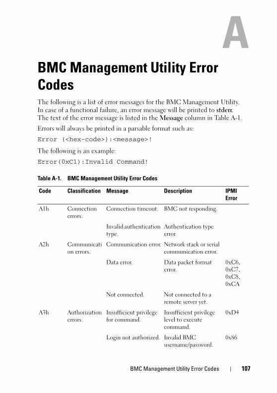
BMC Management Utility Error Codes 107
BMC Management Utility Error CodesThe following is a list of error messages for the BMC Management Utility.
In case of a functional failure, an error message will be printed to stderr.
The text of the error message is listed in the Message column in Table A-1.
Errors will always be printed in a parsable format such as:
Error (<hex-code>):<message>!
The following is an example:
Error(0xC1):Invalid Command!
Table A-1. BMC Management Utility Error Codes
Code Classification Message Description IPMI Error
A1h Connection
errors.
Connection timeout. BMC not responding.
Invalid authentication
type.
Authentication type
error.
A2h Communicati
on errors.
Communication error. Network stack or serial
communication error.
Data error. Data packet format
error.
0xC6,
0xC7,
0xC8,
0xCA
Not connected. Not connected to a
remote server yet.
A3h Authorization
errors.
Insufficient privilege
for command.
Insufficient privilege
level to execute
command.
0xD4
Login not authorized. Invalid BMC
username/password.
0x86
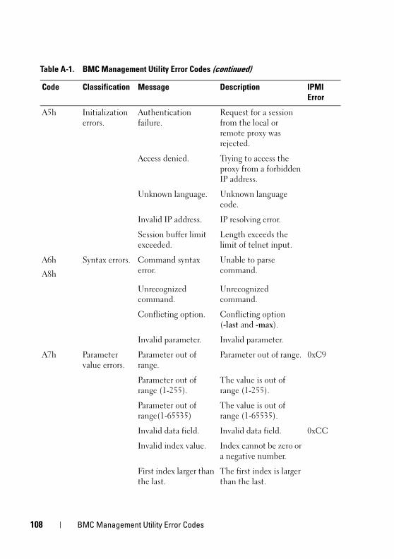
108 BMC Management Utility Error Codes
A5h Initialization
errors.
Authentication
failure.
Request for a session
from the local or
remote proxy was
rejected.
Access denied. Trying to access the
proxy from a forbidden
IP address.
Unknown language. Unknown language
code.
Invalid IP address. IP resolving error.
Session buffer limit
exceeded.
Length exceeds the
limit of telnet input.
A6h
A8h
Syntax errors. Command syntax
error.
Unable to parse
command.
Unrecognized
command.
Unrecognized
command.
Conflicting option. Conflicting option
(-last and -max).
Invalid parameter. Invalid parameter.
A7h Parameter
value errors.
Parameter out of
range.
Parameter out of range. 0xC9
Parameter out of
range (1-255).
The value is out of
range (1-255).
Parameter out of
range(1-65535)
The value is out of
range (1-65535).
Invalid data field. Invalid data field. 0xCC
Invalid index value. Index cannot be zero or
a negative number.
First index larger than
the last.
The first index is larger
than the last.
Table A-1. BMC Management Utility Error Codes (continued)
Code Classification Message Description IPMI Error
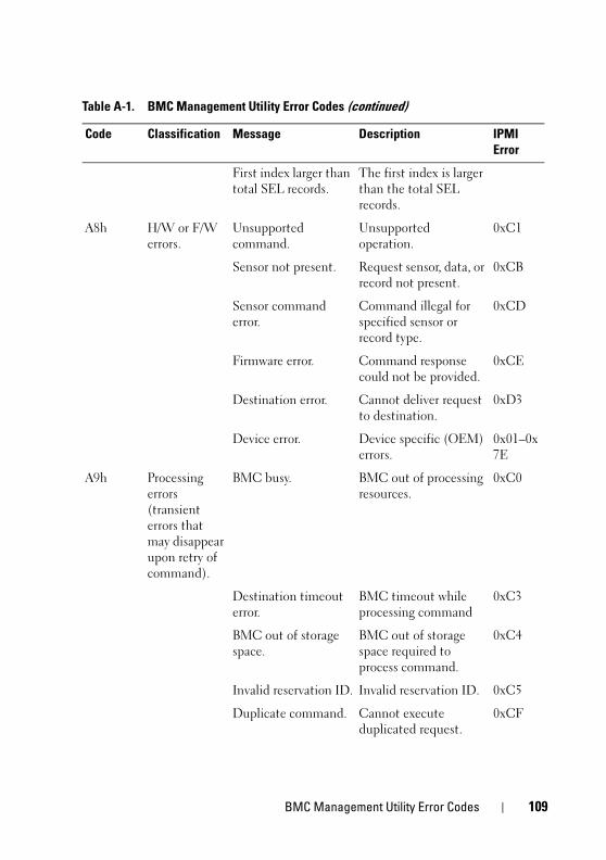
BMC Management Utility Error Codes 109
First index larger than
total SEL records.
The first index is larger
than the total SEL
records.
A8h H/W or F/W
errors.
Unsupported
command.
Unsupported
operation.
0xC1
Sensor not present. Request sensor, data, or
record not present.
0xCB
Sensor command
error.
Command illegal for
specified sensor or
record type.
0xCD
Firmware error. Command response
could not be provided.
0xCE
Destination error. Cannot deliver request
to destination.
0xD3
Device error. Device specific (OEM)
errors.
0x01–0x
7E
A9h Processing
errors
(transient
errors that
may disappear
upon retry of
command).
BMC busy. BMC out of processing
resources.
0xC0
Destination timeout
error.
BMC timeout while
processing command
0xC3
BMC out of storage
space.
BMC out of storage
space required to
process command.
0xC4
Invalid reservation ID. Invalid reservation ID. 0xC5
Duplicate command. Cannot execute
duplicated request.
0xCF
Table A-1. BMC Management Utility Error Codes (continued)
Code Classification Message Description IPMI Error
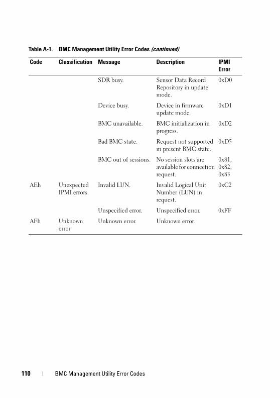
110 BMC Management Utility Error Codes
SDR busy. Sensor Data Record
Repository in update
mode.
0xD0
Device busy. Device in firmware
update mode.
0xD1
BMC unavailable. BMC initialization in
progress.
0xD2
Bad BMC state. Request not supported
in present BMC state.
0xD5
BMC out of sessions. No session slots are
available for connection
request.
0x81,
0x82,
0x83
AEh Unexpected
IPMI errors.
Invalid LUN. Invalid Logical Unit
Number (LUN) in
request.
0xC2
Unspecified error. Unspecified error. 0xFF
AFh Unknown
error
Unknown error. Unknown error.
Table A-1. BMC Management Utility Error Codes (continued)
Code Classification Message Description IPMI Error
Terminal Mode Commands 111
Terminal Mode CommandsThis appendix provides information about terminal mode commands.
Terminal mode allows you to directly connect to the system's Baseboard
Management Controller (BMC) using a serial port connection and execute
text-based commands. Two types of text commands are supported:
• A limited selection of text commands
• Standard binary Intelligent Platform Management Interface (IPMI)
hex-ASCII commands
Configuring Terminal Mode
NOTE: Terminal Mode can be configured through Server Administrator and the Deployment Toolkit (DTK).
To configure Terminal Mode through Server Administrator, complete the
following steps:
1 Log in to the Server Administrator home page for the target system.
2 Click the System object.
3 Click the Main System Chassis object.
4 Click the Remote Access object.
5 The BMC Information window is displayed.
6 Click the Configuration tab.
In the Configuration tab, click Serial Port.
7 Click the Terminal Mode Settings button.
You can configure the Connection Mode Setting, Baud Rate, Flow Control,
and Channel Privilege Level Limit attributes on this screen.
• The Serial communication connection mode for the BMC must be set to
Direct Connect terminal Mode for Dell™ PowerEdge™ x8xx, x9xx, and
xx0x systems.
• External Serial Connector must be configured and set to Remote Access
for PowerEdge x9xx and xx0x systems. This option is available under the
Serial Communication submenu in the BIOS Setup.
112 Terminal Mode Commands
• Disable the RAC serial Console if you have a DRAC 5 installed. Login to
the DRAC GUI, navigate to Serial from Remote Access, and disable
Enable Serial console.
• Set Serial Port 1 for PowerEdge x8xx systems. This option is available in
the BIOS Setup, in the Integrated Devices menu.
Using Terminal Mode
Use the Terminal Mode feature to perform the following tasks:
• Power the server on or off.
• Reset the server.
• Retrieve the server's health status.
• Configure and retrieve the server management subsystems boot options.
• Configure and retrieve the BMC's terminal mode configuration.
• Execute any platform supported binary command specified in the IPMI
specification using the hex-ASCII format.
NOTE: Many of the Terminal Mode features described in this section require an extensive knowledge of IPMI. It is strongly recommended that Terminal Mode users have an advanced understanding of IPMI before using the commands documented in this section.
Security InformationAccess to the BMC using terminal mode is governed by the proper setup of
user names and password. See "Configuring Your Managed System" for more
information. A session must be established with the BMC prior to accepting
any terminal mode commands. A limited selection of text commands and
binary hex-ASCII commands that are assigned the lowest IPMI privilege level
are available prior to session establishment with the BMC.
Since the terminal mode password is sent using clear text, it is highly
desirable that the terminal mode session takes place in a secure location over
a secure link by using a direct connection.

Terminal Mode Commands 113
SyntaxTerminal mode messages follow the general syntax below:
[<message data>]<newline sequence>
Each terminal mode message must be preceded with the left bracket "start”
character and must be ended with a right bracket “stop” character and the
appropriate input new-line sequence.
No input characters are accepted until the start character has been received.
NOTE: Hex-ASCII commands can either use upper or lower-case letters for ASCII representations of hex digits.
Command Length
Terminal mode messages are limited to a maximum length of 122 characters.
This includes the left- and right-brackets, but not control characters.
Character Support
Terminal mode messages are composed of standard printable ASCII
characters. All other characters are treated as illegal characters.
Special Character Handling — <Esc> character
The <Esc> character deletes an entire message prior to submission to the
BMC for processing. If line editing is enabled, and the <Esc> key is followed
by an input newline sequence, the BMC responds by displaying an output
newline sequence. Otherwise, the BMC looks for the next start character.
Special Character Handling — <Delete> or <Backspace> character
The <Backspace> or <Delete> key deletes the last character entered if the
message has not been submitted to the BMC yet.
Special Character Handling — Line Continuation character
Long IPMI messages can be split across multiple lines by using the line
continuation "\" character followed immediately by an input newline
sequence. Line continuation character usage is supported for both text and
hex-ASCII commands.
Special Character Handling — Illegal characters
Any illegal characters received by the BMC clear the message in progress and
the BMC looks for the next start character.
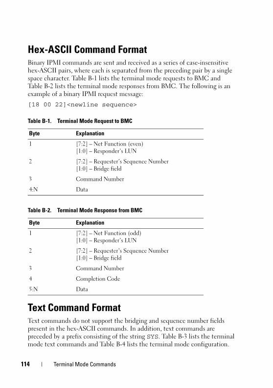
114 Terminal Mode Commands
Hex-ASCII Command FormatBinary IPMI commands are sent and received as a series of case-insensitive
hex-ASCII pairs, where each is separated from the preceding pair by a single
space character. Table B-1 lists the terminal mode requests to BMC and
Table B-2 lists the terminal mode responses from BMC. The following is an
example of a binary IPMI request message:
[18 00 22]<newline sequence>
Text Command FormatText commands do not support the bridging and sequence number fields
present in the hex-ASCII commands. In addition, text commands are
preceded by a prefix consisting of the string SYS. Table B-3 lists the terminal
mode text commands and Table B-4 lists the terminal mode configuration.
Table B-1. Terminal Mode Request to BMC
Byte Explanation
1 [7:2] – Net Function (even)
[1:0] – Responder’s LUN
2 [7:2] – Requester’s Sequence Number
[1:0] – Bridge field
3 Command Number
4:N Data
Table B-2. Terminal Mode Response from BMC
Byte Explanation
1 [7:2] – Net Function (odd)
[1:0] – Responder’s LUN
2 [7:2] – Requester’s Sequence Number
[1:0] – Bridge field
3 Command Number
4 Completion Code
5:N Data
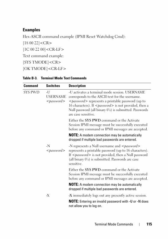
Terminal Mode Commands 115
Examples
Hex-ASCII command example (IPMI Reset Watchdog Cmd):
[18 00 22]<CR>
[1C 00 22 00]<CR-LF>
Text command example:
[SYS TMODE]<CR>
[OK TMODE]<CR-LF>
Table B-3. Terminal Mode Text Commands
Command Switches Description
SYS PWD -U
USERNAME
<password>
-U activates a terminal mode session. USERNAME
corresponds to the ASCII text for the username.
<password> represents a printable password (up to
16 characters). If <password> is not provided, then a
Null password (all binary 0’s) is submitted. Passwords
are case sensitive.
Either the SYS PWD command or the Activate
Session IPMI message must be successfully executed
before any command or IPMI messages are accepted.
NOTE: A modem connection may be automatically dropped if multiple bad passwords are entered.
-N
<password>
-N represents a Null username and <password>
represents a printable password (up to 16 characters).
If <password> is not provided, then a Null password
(all binary 0’s) is submitted. Passwords are case
sensitive.
Either the SYS PWD command or the Activate
Session IPMI message must be successfully executed
before any command or IPMI messages are accepted.
NOTE: A modem connection may be automatically dropped if multiple bad passwords are entered.
-X -X immediately logs out any presently active session.
NOTE: Entering an invalid password with -U or -N does not allow you to log on.
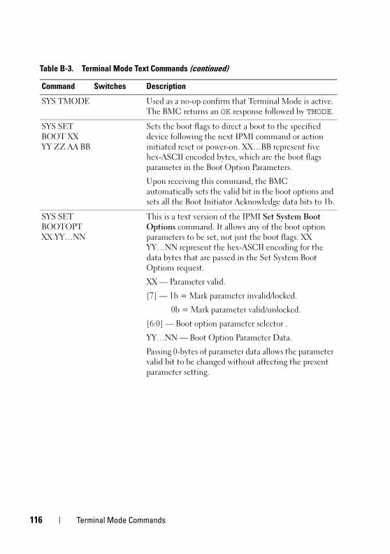
116 Terminal Mode Commands
SYS TMODE Used as a no-op confirm that Terminal Mode is active.
The BMC returns an OK response followed by TMODE.
SYS SET
BOOT XX
YY ZZ AA BB
Sets the boot flags to direct a boot to the specified
device following the next IPMI command or action
initiated reset or power-on. XX…BB represent five
hex-ASCII encoded bytes, which are the boot flags
parameter in the Boot Option Parameters.
Upon receiving this command, the BMC
automatically sets the valid bit in the boot options and
sets all the Boot Initiator Acknowledge data bits to 1b.
SYS SET
BOOTOPT
XX YY…NN
This is a text version of the IPMI Set System Boot
Options command. It allows any of the boot option
parameters to be set, not just the boot flags. XX
YY…NN represent the hex-ASCII encoding for the
data bytes that are passed in the Set System Boot
Options request.
XX — Parameter valid.
[7] — 1b = Mark parameter invalid/locked.
0b = Mark parameter valid/unlocked.
[6:0] — Boot option parameter selector .
YY…NN — Boot Option Parameter Data.
Passing 0-bytes of parameter data allows the parameter
valid bit to be changed without affecting the present
parameter setting.
Table B-3. Terminal Mode Text Commands (continued)
Command Switches Description
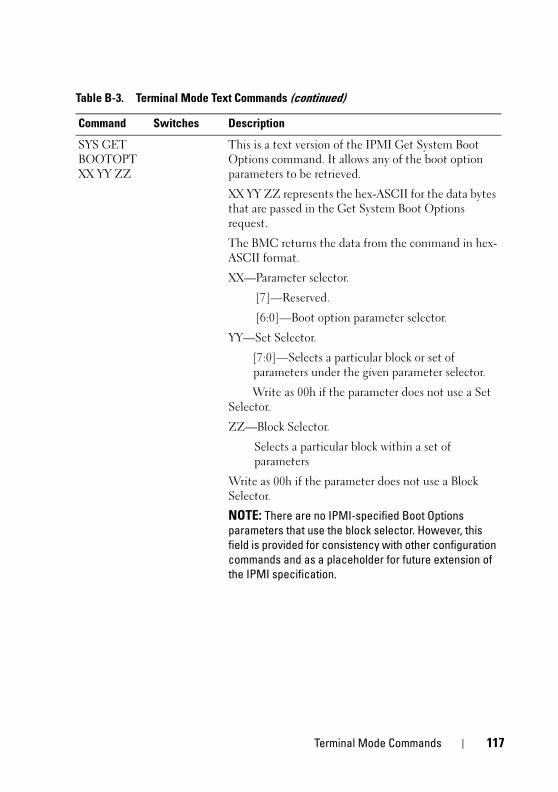
Terminal Mode Commands 117
SYS GET
BOOTOPT
XX YY ZZ
This is a text version of the IPMI Get System Boot
Options command. It allows any of the boot option
parameters to be retrieved.
XX YY ZZ represents the hex-ASCII for the data bytes
that are passed in the Get System Boot Options
request.
The BMC returns the data from the command in hex-
ASCII format.
XX—Parameter selector.
[7]—Reserved.
[6:0]—Boot option parameter selector.
YY—Set Selector.
[7:0]—Selects a particular block or set of
parameters under the given parameter selector.
Write as 00h if the parameter does not use a Set
Selector.
ZZ—Block Selector.
Selects a particular block within a set of
parameters
Write as 00h if the parameter does not use a Block
Selector.
NOTE: There are no IPMI-specified Boot Options parameters that use the block selector. However, this field is provided for consistency with other configuration commands and as a placeholder for future extension of the IPMI specification.
Table B-3. Terminal Mode Text Commands (continued)
Command Switches Description
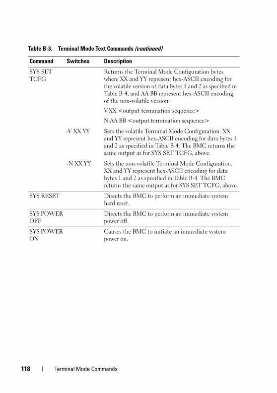
118 Terminal Mode Commands
SYS SET
TCFG
Returns the Terminal Mode Configuration bytes
where XX and YY represent hex-ASCII encoding for
the volatile version of data bytes 1 and 2 as specified in
Table B-4, and AA BB represent hex-ASCII encoding
of the non-volatile version.
V:XX <output termination sequence>
N:AA BB <output termination sequence>
-V XX YY Sets the volatile Terminal Mode Configuration. XX
and YY represent hex-ASCII encoding for data bytes 1
and 2 as specified in Table B-4. The BMC returns the
same output as for SYS SET TCFG, above.
-N XX YY Sets the non-volatile Terminal Mode Configuration.
XX and YY represent hex-ASCII encoding for data
bytes 1 and 2 as specified in Table B-4. The BMC
returns the same output as for SYS SET TCFG, above.
SYS RESET Directs the BMC to perform an immediate system
hard reset.
SYS POWER
OFF
Directs the BMC to perform an immediate system
power off.
SYS POWER
ON
Causes the BMC to initiate an immediate system
power on.
Table B-3. Terminal Mode Text Commands (continued)
Command Switches Description

Terminal Mode Commands 119
SYS
HEALTH
QUERY
Causes the BMC to return a high level version of the
system health status in terse format. The BMC returns
a string with the following format if the command is
accepted.
PWR:zzz H:xx T:xx V:xx PS:xx C:xx D:xx S:xx O:xx
Where:
PWR is system POWER state.
H is overall Health.
T is Temperature.
V is Voltage.
PS is Power Supply subsystem.
C is cooling subsystem (Fans).
D is Hard Drive/RAID Subsystem.
S is physical Security.
O is Other (OEM).
zzz is: ON, OFF (soft-off or mechanical off), SLP
(sleep - used when sleep level cannot be
distinguished), S4, S3, S2, S1, ?? (unknown).
and xx is: ok, nc, cr, nr, uf, or ?? where:
ok = OK (monitored parameters within normal
operating ranges).
nc = non-critical ("warning": hardware outside normal operating range).
cr = critical ("fatal": hardware exceeding specified ratings).
nr = non-recoverable ("potential damage": system hardware in jeopardy or damaged).
uf = unspecified fault (fault detected, but severity
unspecified).
?? = status not available/unknown (typically because
system power is OFF).
Table B-3. Terminal Mode Text Commands (continued)
Command Switches Description
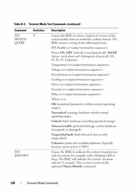
120 Terminal Mode Commands
SYS
HEALTH
QUERY
-V Causes the BMC to return a high level version of the
system health status in multi-line verbose format. The
BMC returns a string of the following format:
SYS Health:xx<output termination sequence>.
Power: ON, OFF (soft-off or mechanical off), SLEEP
(sleep - used when can't distinguish sleep level), S4,
S3, S2, S1, Unknown.
Temperature:xx<output termination sequence>.
Voltage:xx<output termination sequence>.
PowerSystem:xx<output termination sequence>.
Cooling:xx<output termination sequence>.
Drives:xx<output termination sequence>.
Security:xx<output termination sequence>.
Other:xx<output termination sequence>.
Where xx is:
OK (monitored parameters within normal operating
ranges).
Non-critical (warning: hardware outside normal
operating range).
Critical (fatal: hardware exceeding specified ratings).
Non-recoverable (potential damage: system hardware
in jeopardy or damaged).
Unspecified fault (fault detected, but severity
unspecified).
Unknown (status not available/unknown (typically
because system power is OFF).
SYS
IDENTIFY
Causes the BMC to indicate the system’s location in a
rack of systems, for example, with a blinking LED or
beep. The BMC will indicate the system’s location
only for 15 seconds. This is a text version of the
optional Chassis Identify command.
Table B-3. Terminal Mode Text Commands (continued)
Command Switches Description

Terminal Mode Commands 121
SYS
IDENTIFY
-ON<XX> Causes the BMC to indicate the system’s location, for
example, with a blinking LED or beep for a specific
period of time.
XX is an optional hex-ASCII byte representing the
number of seconds the BMC is to cause the system to
identify itself. If XX is not provided, the BMC will
indicate the system’s location only for 15 seconds. This is
a text version of the optional Chassis Identify command.
SYS
IDENTIFY
-OFF Causes the BMC to stop indicating the system’s
location. This has no effect if the system is not
currently identifying itself. This is a text version of the
optional Chassis Identify command.
Table B-4. Terminal Mode Configuration
Byte Explanation
1 [7:6]—Reserved.
[5]—Line Editing.
0b = Disable.
1b = Enable (Factory default).
[4]—Reserved.
[3:2]—Delete control (only applies when line editing is enabled).
00b = BMC outputs a <Delete> character when <Backspace> or
<Delete> is received.
01b = BMC outputs a <Backspace>< SP ><Backspace>
sequence when <Backspace> or
<Delete> is received (Factory default).
[1]—Echo control0b = No echo 1b = Echo (BMC echoes
characters it receives) (Factory default).
[0]—Handshaking—BMC outputs a [SYS]<newline> after
receiving each terminal mode IPMI message and is ready to accept
the next message.
0b = Disable.
1b = Enable (Factory default).
Table B-3. Terminal Mode Text Commands (continued)
Command Switches Description

122 Terminal Mode Commands
2 [7:4]—Output newline sequence (BMC to console). Selects what
characters the BMC uses as the <newline> sequence when the
BMC writes a line to the console in Terminal Mode.
0h = no termination sequence.
1h = <CR-LF> (Factory default)
2h = <NULL>
3h = <CR>
4h = <LF-CR>
5h = <LF>
All other = reserved
[3:0]—Input newline sequence (Console to BMC). Selects what
characters the console uses as the newline sequence when writing
to the BMC in Terminal Mode.
0h = reserved
1h = <CR> (Factory default)
2h = <NULL>
All other = reserved
Table B-4. Terminal Mode Configuration (continued)
Byte Explanation

Escape Key Sequences 123
Escape Key Sequences Console redirection uses ANSI or VT100/220 terminal emulation, which are
limited to basic ASCII characters. There are no function keys, arrow keys, or
control keys in this character set. However, most BIOS software requires the
use of function keys and control keys for ordinary actions. Specific function
keys and escape keys can be emulated by using a special key sequence, called
an escape sequence, to represent a specific key.
Use the Escape sequences, listed in the following table, for keys while setting
console redirection in BIOS through serial port. These keys are also listed
during BIOS POST. Press the spacebar to pause and view the list. Supported
sequences are also listed in the history of the system’s telnet client.
Table C-1. Escape sequences for specific keys
Key Supported sequences
F10 <Esc><0>
F12 <Esc><@>
<Ctrl><M> <Esc><Ctrl><M>
<Ctrl><H> <Esc><Ctrl><H>
<Ctrl><I> <Esc><Ctrl><I>
<Ctrl><J> <Esc><Ctrl><J>
<Alt><X> <Esc><X><X>
<Ctrl><Alt><Del> <Esc><R><Esc><r><Esc><R>

124 Escape Key Sequences

Serial Port Console Redirection 125
Serial Port Console Redirection
Serial CommunicationFor PowerEdge x9xx and xx0x servers, serial console redirection can be
accomplished using COM1 or COM2.
Console Redirection Via COM1
To activate serial console redirection via COM1, you must configure the
following settings:
Set Serial Communication-> Serial Communication to On with Console
Redirection via COM1
Set Serial Communication-> External Serial Connector to COM1
Console Redirection Via COM2
Console Redirection via COM2 can be used to redirect either to the external
connector or to the remote access device, such as a BMC or DRAC 5, for
Serial Over LAN (SOL) communication.
To activate serial console redirection via COM2, you must configure the
following settings:
Set Serial Communication-> Serial Communication to On with Console
Redirection via COM2
Set Serial Communication-> External Serial Connector to COM2
NOTE: If the console redirection is used for SOL then the External Serial Connector setting does not need to be configured.
When using COM2 for console redirection regardless of whether you redirect to
the external connector or for SOL, the BIOS reads the SOL baud rate from the
BMC and uses that setting to activate console redirection. SOL baud rate can
be configured using the Dell Deployment Toolkit, OMSA, DRAC, or the BMU.
126 Serial Port Console Redirection
Serial Terminal Communication to BMC or DRAC
Serial Terminal Mode allows you to directly connect to the BMC or DRAC
using a serial port connection and execute text-based commands. Refer to the
Appendix B for information about configuring your BMC and DRAC for Serial
Terminal Communication as well as available Terminal Mode Commands.
In Terminal Mode, the BMC or the DRAC, if present, support Escape key
sequences that allow switching between the Serial Terminal Connection and
the connection to the system COM2 port. This can be combined with the
Console Redirection via COM2 (see "Console Redirection Via COM2") to
switch between viewing the system console redirection and communicating
to BMC or DRAC to execute the terminal commands such as system reset.
NOTE: For this combined functionality, Serial Communication baud rate and the SOL baud rate must be set to the same value.
When in terminal mode, to switch the connection to the system COM2 port
use:
<Esc> +<Shift> <q>
When connected to the system COM2 port, to go back to the terminal mode
use:
<Esc> +<Shift> <9>
SPCR TableThe Serial Port Console Redirection (SPCR) table provides information about
how the system firmware and service processor use the out-of-band (OOB)
management port. For example, if the OOB Management port is a serial port,
the SPCR table contains information such as serial port number, baud terminal
type, and other settings used for OOB communication. The SPCR table is read
by the Special Administrative Console (SAC) for console redirection and
configures itself automatically during a bootable CD installation.
The SPCR table is automatically enabled if the system service processor
supports Emergency Management Services (EMS) such as console redirection.
If it is not configured automatically, you must configure SPCR to match BMC
settings by adding the following parameters to the unattend.txt file.
NOTE: The unattend.txt file is automatically created after installation.
Serial Port Console Redirection 127
[Data]
EMSPort
EMSBaudrate
Where,
EMSPort = Port used for serial communication. For example, COM1 or COM2.
EMSBaudrate = Configured baud rate for communication. The minimum
supported baud rates for supported Dell™ PowerEdge™ systems is 19200.
Serial Console redirection With SOL Proxy
Configuring Linux for Serial Redirection During Boot
The "SysRq key" is a key sequence that allows basic commands to be passed
directly to the kernel for debugging. Under some circumstances, it can also be
used to reboot remote managed systems. The serial console uses the RS-232
break function as the SysRq key. A "break" is a period of no transmission on
the serial line. To configure the "Sysrq" key in systems running Linux, follow
the instructions given below:
NOTE: The following instructions are specific to the Linux GRand Unified Bootloader (GRUB). Similar changes would be necessary for using a different boot loader.
NOTE: In configuring the client VT100 emulation window, you must set the window or application that is displaying the redirected console to 25 rows x 80 columns to ensure proper text display; otherwise, some text screens may be garbled.
Edit the file /etc/grub.conf, as follows. See the sample file that follows, which
shows the changes described in this procedure.
1 Add the following two new lines in the general settings section of the file:
serial --unit=0 --speed=19200terminal --timeout=10 serial
2 Append two options to the kernel line:
kernel ............. console=ttyS0,19200
3 If the /etc/grub.conf contains a splashimage directive, you must
comment it out.
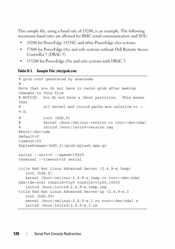
128 Serial Port Console Redirection
This sample file, using a baud rate of 19200, is an example. The following
maximum baud rates are allowed for BMC serial communication and SOL:
• 19200 for PowerEdge 1425SC and other PowerEdge x8xx systems.
• 57600 for PowerEdge x9xx and xx0x systems without Dell Remote Access
Controller 5 (DRAC 5).
• 115200 for PowerEdge x9xx and xx0x systems with DRAC 5.
Table D-1. Sample File: /etc/grub.con
# grub.conf generated by anaconda#Note that you do not have to rerun grub after making changes to this file# NOTICE: You do not have a /boot partition. This means that# all kernel and initrd paths are relative to /, e.g.
# root (hd0,0)# kernel /boot/vmlinuz-version ro root=/dev/sdal# initrd /boot/initrd-version.img#boot=/dev/sdadefault=0timeout=10#splashimage=(hd0,2)/grub/splash.xpm.gz
serial --unit=0 --speed=19200terminal --timeout=10 serial
title Red Hat Linux Advanced Server (2.4.9-e.3smp)root (hd0,0)kernel /boot/vmlinuz-2.4.9-e.3smp ro root=/dev/sda1
hda=ide-scsi console=tty0 console=ttyS0,19200initrd /boot/initrd-2.4.9-e.3smp.img
title Red Hat Linux Advanced Server-up (2.4.9-e.3root (hd0,00)kernel /boot/vmlinuz-2.4.9-e.3 ro root=/dev/sda1 sinitrd /boot/initrd-2.4.9-e.3.im

Serial Port Console Redirection 129
Additional information for editing the grub.conf:
1 You may need to disable GRUB's graphical interface and use the text-based
interface instead; otherwise, the GRUB screen will not be displayed in
BMU console redirection. To do so, comment out the line starting with
splashimage.
2 If you have multiple options in GRUB and you want all of them to start a
console session through the BMU serial connection, add console=ttyS1,19200 to all options. The preceding example shows console=ttyS0,19200 added to only the first option.
Enabling Login to the Console After Boot
Edit the file /etc/inittab, as follows:
Add a new line to configure a getty on the COM1 serial port:
co:2345:respawn:/sbin/agetty -h -L 19200 ttyS0 vt100
See the sample file, which shows the addition of the new line.

130 Serial Port Console Redirection
Table D-2. Sample File: /etc/innitab
#
# inittab This file describes how the INIT process should set up# the system in a certain run-level.
## Author: Miquel van Smoorenburg, <[email protected]# Modified for RHS Linux by Marc Ewing and Donnie Barnes#
# Default runlevel. The runlevels used by RHS are:# 0 - halt (Do NOT set initdefault to this)# 1 - Single user mode# 2 - Multiuser, without NFS (The same as 3, if you do not have# networking)# 3 - Full multiuser mode# 4 - unused# 5 - X11# 6 - reboot (Do NOT set initdefault to this)#id:3:initdefault:
# System initialization.si::sysinit:/etc/rc.d/rc.sysinit
l0:0:wait:/etc/rc.d/rc 0
l1:1:wait:/etc/rc.d/rc 1
l2:2:wait:/etc/rc.d/rc 2
l3:3:wait:/etc/rc.d/rc 3
l4:4:wait:/etc/rc.d/rc 4
l5:5:wait:/etc/rc.d/rc 5
l6:6:wait:/etc/rc.d/rc 6

Serial Port Console Redirection 131
# Things to run in every runlevel.ud::once:/sbin/update
# Trap CTRL-ALT-DELETEca::ctrlaltdel:/sbin/shutdown -t3 -r now
# When our UPS tells us power has failed, assume we have a few# minutes of power left. Schedule a shutdown for 2 minutes from now.# This does, of course, assume you have power installed and your# UPS is connected and working correctly. pf::powerfail:/sbin/shutdown -f -h +2 "Power Failure; System Shutting Down"# If power was restored before the shutdown kicked in, cancel it.pr:12345:powerokwait:/sbin/shutdown -c "Power Restored; Shutdown Cancelled"
# Run gettys in standard runlevelsco:2345:respawn:/sbin/agetty -h -L 19200 ttyS0 vt1001:2345:respawn:/sbin/mingetty tty12:2345:respawn:/sbin/mingetty tty23:2345:respawn:/sbin/mingetty tty34:2345:respawn:/sbin/mingetty tty45:2345:respawn:/sbin/mingetty tty56:2345:respawn:/sbin/mingetty tty6
# Run xdm in runlevel 5# xdm is now a separate servicex:5:respawn:/etc/X11/prefdm -nodaemon
Table D-2. Sample File: /etc/innitab (continued)

132 Serial Port Console Redirection
Edit the file /etc/securetty, as follows:
Add a new line, with the name of the serial tty for COM1:
ttyS0
See the sample file, which shows the addition of the new line.
Table D-3. Sample File: /etc/securetty
vc/1vc/2vc/3vc/4vc/5vc/6vc/7vc/8vc/9vc/10vc/11tty1tty2tty3tty4tty5tty6tty7tty8tty9tty10tty11ttyS0

Glossary 133
Glossary
The following list defines or identifies technical terms, abbreviations, and
acronyms used in your system documents.
adapter cardAn expansion card that plugs into an expansion-card connector on the system's
system board. An adapter card adds some specialized function to the system by
providing an interface between the expansion bus and a peripheral device.
Examples of adapter cards include network cards, sound cards, and SCSI adapters.
ANSIAbbreviation for American National Standards Institute.
APIAbbreviation for application program interface, which is a set of routines,
protocols, and tools for building software applications that act as an interface
between the operating system and application programs.
ArgumentThe value supplied with an option, such as in the following command line
instance:
utilname --option=argument
ARPAcronym for Address Resolution Protocol, which is a method for finding a host’s
Ethernet address from its Internet address.
ASCIIAcronym for American Standard Code for Information Interchange. A text file
containing only characters from the ASCII character set (usually created with a
text editor, such as Notepad in Microsoft®
Windows®
), is called an ASCII file.
asset tag codeAn individual code assigned to a system, usually by a system administrator, for
security or tracking purposes.
134 Glossary
autoexec.bat fileThe autoexec.bat file is executed when you boot your system (after executing any
commands in the config.sys file). This start-up file contains commands that
define the characteristics of each device connected to your system, and it finds
and executes programs stored in locations other than the active directory.
backupA copy of a program or data file. As a precaution, you should back up your system's
hard drive on a regular basis. Before making a change to the configuration of your
system, you should back up important start-up files from your operating system.
baud rateA measurement of data transmission speed. For example, modems are designed
to transmit data at one or more specified baud rate(s) through the COM (serial)
port of a system.
binaryA base-2 numbering system that uses 0 and 1 to represent information. The system
performs operations based on the ordering and calculation of these numbers.
BIOSAcronym for basic input/output system. Your system's BIOS contains programs
stored on a flash memory chip. The BIOS controls the following:
• Communications between the microprocessor and peripheral devices, such as
the keyboard and the video adapter
• Miscellaneous functions, such as system messages
bitThe smallest unit of information interpreted by your system.
BMCAbbreviation for baseboard management controller, which is a controller that
provides the intelligence in the IPMI structure.
boot routineWhen you start your system, it clears all memory, initializes devices, and loads
the operating system. Unless the operating system fails to respond, you can reboot
(also called warm boot) your system by pressing <Ctrl><Alt><Del>;
otherwise, you must perform a cold boot by pressing the reset button or by turning
the system off and then back on.
Glossary 135
bootable disketteYou can start your system from a diskette. To make a bootable diskette on a system
running Windows, insert a diskette in the diskette drive, type sys a: at the
command line prompt, and press <Enter>. Use this bootable diskette if your
system will not boot from the hard drive.
busAn information pathway between the components of a system. Your system
contains an expansion bus that allows the microprocessor to communicate with
controllers for all the various peripheral devices connected to the system. Your
system also contains an address bus and a data bus for communications between
the microprocessor and RAM.
byteEight contiguous bits of information, the basic data unit used by your system.
cacheA fast storage area that keeps a copy of data or instructions for quicker data
retrieval. For example, your system's BIOS may cache ROM code in faster RAM.
Or, a disk-cache utility may reserve RAM in which to store frequently accessed
information from your system's disk drives; when a program makes a request to a
disk drive for data that is in the cache, the disk-cache utility can retrieve the data
from RAM faster than from the disk drive.
CD-ROMAbbreviation for compact disc read-only memory. CD drives use optical
technology to read data from CDs. CDs are read-only storage devices; you cannot
write new data to a CD with standard CD drives.
CHAPAcronym for Challenge-Handshake Authentication Protocol, an authentication
scheme used by PPP servers to validate the identity of the originator of the
connection upon connection or any time later.
CLIAbbreviation for command line interface.

136 Glossary
CommandThe combination of an option and argument or just an option if no argument is
required, such as in the following command line instances:
utilname --option
utilname --option=argument
command line instanceA series of valid commands, options, and arguments typed in the command line.
For example, the Deployment Toolkit utility name and all necessary options and
arguments as they are entered through the OS shell:
A:>utilname --option --option=argument
COMn
The device names for the first through fourth serial ports on your system are
COM1, COM2, COM3, and COM4. The default interrupt for COM1 and COM3
is IRQ4, and the default interrupt for COM2 and COM4 is IRQ3. Therefore, you
must be careful when configuring software that runs a serial device so that you
don't create an interrupt conflict.
config.sys fileThe config.sys file is executed when you boot your system (before running any
commands in the autoexec.bat file). This start-up file contains commands that
specify which devices to install and which drivers to use. This file also contains
commands that determine how the operating system uses memory and controls files.
console redirectionConsole redirection is a function that directs a managed system’s display screen,
mouse functions, and keyboard functions to the corresponding devices on a
management station. You may then use the management station’s system console
to control the managed system.
controllerA chip that controls the transfer of data between the microprocessor and memory
or between the microprocessor and a peripheral device such as a disk drive or the
keyboard.
control panelThe part of the system that contains indicators and controls, such as the power
switch, hard drive access indicator, and power indicator.

Glossary 137
conventional memoryThe first 640 KB of RAM. Conventional memory is found in all systems. Unless
they are specially designed, programs run from the Windows Command Prompt
are limited to running in conventional memory.
CPUAbbreviation for central processing unit. See also microprocessor.
device driverA program that allows the operating system or some other program to interface
correctly with a peripheral device, such as a printer. Some device drivers—such
as network drivers—must be loaded from the config.sys file (with a device=
statement) or as memory-resident programs (usually, from the autoexec.bat file).
Others—such as video drivers—must load when you start the program for which
they were designed.
DHCPAbbreviation for Dynamic Host Configuration Protocol, a protocol that provides
a means to dynamically allocate IP addresses to computers on a LAN.
DIMMAcronym for dual in-line memory module. A small circuit board containing
DRAM chips that connects to the system board.
directoryDirectories help keep related files organized on a disk in a hierarchical, "inverted
tree" structure. Each disk has a "root" directory; for example, a C:\> prompt
normally indicates that you are at the root directory of hard drive C. Additional
directories that branch off of the root directory are called subdirectories.
Subdirectories may contain additional directories branching off of them.
DKSAbbreviation for dynamic kernel support.
DTKAbbreviation for Deployment ToolKit.
DMAAbbreviation for direct memory access. A DMA channel allows certain types of
data transfer between RAM and a device to bypass the microprocessor.

138 Glossary
DRAC IIAcronym for Dell OpenManage™ Remote Assistant Card, version 2.
DRAC IIIAcronym for Dell™ Remote Access Card III.
DRAC III/XTAcronym for Dell Remote Access Card III/XT.
DRAC 4Acronym for Dell Remote Access Card 4.
DRAC MCAcronym for Dell Remote Access Card MC.
DRAMAcronym for dynamic random-access memory. A system's RAM is usually made
up entirely of DRAM chips. Because DRAM chips cannot store an electrical charge
indefinitely, your system continually refreshes each DRAM chip in the system.
EEPROMAcronym for electrically erasable programmable read-only memory.
EIDEAbbreviation for enhanced integrated drive electronics. EIDE devices add one or
more of the following enhancements to the traditional IDE standard:
• Data transfer rates of up to 16 MB/sec
• Support for drives other than just hard drives, such as CD and tape drives
• Support for hard drives with capacities greater than 528 MB
• Support for up to two controllers, each with up to two devices attached
EMSAbbreviation for Expanded Memory Specification.
EPROMAcronym for erasable programmable read-only memory.
ERAAbbreviation for embedded remote access.
Glossary 139
ERA/MCAbbreviation for embedded remote access modular computer. See modular
system.
ERA/OAbbreviation for embedded remote access option.
ESMAbbreviation for embedded systems management, which is a set of instruction
coding in system software and firmware that notifies a user about potential
hardware problems on a system.
expanded memoryA technique for accessing RAM above 1 MB. To enable expanded memory on
your system, you must use an EMM. You should configure your system to support
expanded memory only if you run application programs that can use (or require)
expanded memory.
extended memoryRAM above 1 MB. Most software that can use it, such as the Windows operating
system, requires that extended memory be under the control of an XMM.
external cache memoryA RAM cache using SRAM chips. Because SRAM chips operate at several times
the speed of DRAM chips, the microprocessor can retrieve data and instructions
faster from external cache memory than from RAM.
FEPROMAcronym for flash erasable programmable read-only memory. Flash memory is a
kind of nonvolatile storage device similar to EEPROM, but the erasing is done
only in blocks or the entire chip.
firmwareSoftware (programs or data) that has been written onto read-only memory
(ROM). Firmware can boot and operate a device. Each controller contains
firmware which helps provide the controller's functionality.
flash biosA BIOS that is stored in flash memory rather than in ROM. A flash BIOS chip
can be updated in place, whereas a ROM BIOS must be replaced with a
newer chip.

140 Glossary
flash memoryA type of EEPROM chip that can be reprogrammed from a utility on diskette
while still installed in a system; most EEPROM chips can only be rewritten with
special programming equipment.
formatTo prepare a hard drive or diskette for storing files. An unconditional format deletes
all data stored on the disk.
FRUAbbreviation for field replaceable unit, which identifies a module or component
that will typically be replaced in its entirety as part of a field service repair operation.
function commandsCommands that specify an action to be performed.
GBAbbreviation for gigabyte(s). A gigabyte equals 1024 megabytes or 1,073,741,824
bytes.
graphics modeA video mode that can be defined as x horizontal by y vertical pixels by z colors.
GUIAcronym for graphical user interface.
GUIDAbbreviation for Globally Unique Identifier, which is a random number used in
software applications. Each generated GUID is supposed to be unique.
hAbbreviation for hexadecimal. A base-16 numbering system, often used in
programming to identify addresses in the system's RAM and I/O memory
addresses for devices. The sequence of decimal numbers from 0 through 16, for
example, is expressed in hexadecimal notation as: 0, 1, 2, 3, 4, 5, 6, 7, 8, 9, A, B,
C, D, E, F, 10. In text, hexadecimal numbers are often followed by h.
HBAAbbreviation for host bus adapter. A PCI adapter card that resides in the system
whose only function is to convert data commands from PCI-bus format to storage
interconnect format (examples: SCSI, Fibre Channel) and communicate directly
with hard drives, tape drives, CD drives, or other storage devices.
Glossary 141
HMAAbbreviation for high memory area. The first 64 KB of extended memory above
1 MB. A memory manager that conforms to the XMS can make the HMA a direct
extension of conventional memory. Also see XMM.
host adapterA host adapter implements communication between the system's bus and the
controller for a peripheral device. (hard drive controller subsystems include
integrated host adapter circuitry.) To add a SCSI expansion bus to your system,
you must install or connect the appropriate host adapter.
HTTPAbbreviation for Hypertext Transfer Protocol. HTTP is the client-server TCP/IP
protocol used on the World Wide Web for the exchange of HTML documents.
HTTPSAbbreviation for HyperText Transmission Protocol, Secure. HTTPS is a variant
of HTTP used by Web browsers for handling secure transactions. HTTPS is a
unique protocol that is simply SSL underneath HTTP. You need to use "https://"
for HTTP URLs with SSL, whereas you continue to use "http://" for HTTP URLs
without SSL.
IDAbbreviation for identifier, commonly used when referring to a user identifier
(user ID), object identifier (object ID), or hardware identifier (controller ID).
IDEAbbreviation for Integrated Drive Electronics. IDE is a computer system
interface, used primarily for hard drives and CDs.
I/OAbbreviation for input/output. The keyboard is an input device, and a printer is
an output device. In general, I/O activity can be differentiated from
computational activity. For example, when a program sends a document to the
printer, it is engaging in output activity; when the program sorts a list of terms,
it is engaging in computational activity.
IP addressAbbreviation for Internet Protocol address. See TCP/IP.
142 Glossary
IPMIAbbreviation for Intelligent Platform Management Interface, which is an industry
standard for management of peripherals used in enterprise systems based on
Intel®
architecture. The key characteristic of IPMI is that inventory, monitoring,
logging, and recovery control functions are available independent of the main
processors, BIOS, and operating system.
IRQAbbreviation for interrupt request. A signal that data is about to be sent to or
received by a peripheral device travels by an IRQ line to the microprocessor. Each
peripheral connection must be assigned an IRQ number. For example, the first
serial port in your system (COM1) is assigned to IRQ4 by default. Two devices
can share the same IRQ assignment, but you cannot operate both devices
simultaneously.
KBAbbreviation for kilobyte(s), 1024 bytes.
key combinationA command requiring you to press multiple keys at the same time. For example,
you can reboot your system by pressing the <Ctrl><Alt><Del> key combination.
LANAcronym for local area network. A LAN system is usually confined to the same
building or a few nearby buildings, with all equipment linked by wiring dedicated
specifically to the LAN.
local busOn a system with local-bus expansion capability, certain peripheral devices (such
as the video adapter circuitry) can be designed to run much faster than they would
with a traditional expansion bus. Some local-bus designs allow peripherals to run
at the same speed and with the same width data path as the system's microprocessor.
LPTnThe device names for the first through third parallel printer ports on your system
are LPT1, LPT2, and LPT3.
LRAAbbreviation for local response agent.
Glossary 143
MBAbbreviation for megabyte(s). The term megabyte means 1,048,576 bytes;
however, when referring to hard drive storage, the term is often rounded to mean
1,000,000 bytes.
memoryA system can contain several different forms of memory, such as RAM, ROM,
and video memory. Frequently, the word memory is used as a synonym for RAM;
for example, an unqualified statement such as "a system with 16 MB of memory"
refers to a system with 16 MB of RAM.
memory addressA specific location, usually expressed as a hexadecimal number, in the system's RAM.
memory managerA utility that controls the implementation of memory in addition to conventional
memory, such as extended or expanded memory.
memory moduleA small circuit board containing DRAM chips that connects to the system board.
MHzAbbreviation for megahertz.
microprocessorThe primary computational chip inside the system that controls the interpretation
and execution of arithmetic and logic functions. Software written for one
microprocessor must usually be revised to run on another microprocessor. CPU
is a synonym for microprocessor.
modemA device that allows your system to communicate with other systems over
telephone lines.
modular systemA system that can include multiple server modules. Each server module functions
as an individual system. To function as a system, a server module is inserted into
a chassis which includes power supplies, fans, a system management module, and
at least one network switch module. The power supplies, fans, system
management module, and network switch module are shared resources of the
server modules in the chassis. See server module.

144 Glossary
NICAcronym for network interface controller.
NVRAMAcronym for nonvolatile random-access memory. Memory that does not lose its
contents when you turn off your system. NVRAM is used for maintaining the
date, time, and system configuration information.
option An argument to a command that modifies its function rather than providing data
and is usually set off by a delimiter such as - or /. Some options may or must be
followed by a value, for example:
utilname -option=argument
parameterA value or option that you specify to a program. A parameter is sometimes called
a switch or an argument.
partitionYou can divide a hard drive into multiple physical sections called partitions with
the fdisk command. Each partition can contain multiple logical drives. After
partitioning the hard drive, you must format each logical drive with the format
command.
PCIAbbreviation for Peripheral Component Interconnect. The predominant 32-bit
or 64-bit local-bus standard developed by Intel Corporation.
PCMCIAPersonal Computer Memory Card International Association. An international
trade association that has developed standards for devices, such as modems and
external hard drives, that can be plugged into portable computers.
PERCAcronym for Expandable RAID controller.
peripheral deviceAn internal or external device—such as a printer, a disk drive, or a keyboard—
connected to a system.

Glossary 145
Plug and PlayAn industry-standard specification that makes it easier to add hardware devices
to personal computers. Plug and Play provides automatic installation and
configuration, compatibility with existing hardware, and dynamic support of
mobile computing environments.
POSTAcronym for power-on self-test. Before the operating system loads when you turn
on your system, the POST tests various system components such as RAM, the
disk drives, and the keyboard.
pre-operating system environmentA shell environment, such as DOS, used to configure system hardware before a
major operating system, such as Microsoft Windows or Red Hat®
Enterprise
Linux, is installed.
program diskette setThe set of diskettes from which you can perform a complete installation of an
operating system or application program. When you reconfigure a program, you
often need its program diskette set.
PXEAbbreviation for Pre-boot eXecution Environment.
RACAcronym for remote access controller.
RAIDAcronym for redundant array of independent drives.
RAMAcronym for random-access memory. A system's primary temporary storage area
for program instructions and data. Each location in RAM is identified by a number
called a memory address. Any information stored in RAM is lost when you turn
off your system.
RAM diskA memory-resident program that emulates a hard drive.
146 Glossary
read-only fileA read-only file is one that you are prohibited from editing or deleting. A file can
have read-only status if:
• Its read-only attribute is enabled.
• It resides on a physically write-protected diskette or on a diskette in a write-
protected drive.
• It is located on a network in a directory to which the system administrator has
assigned read-only rights to you.
readme fileA text file included with a software package or hardware product that contains
information supplementing or updating the documentation for the software or
hardware. Typically, readme files provide installation information, describe new
product enhancements or corrections that have not yet been documented, and
list known problems or other things you need to be aware of as you use the software
or hardware.
ROMAcronym for read-only memory. Your system contains some programs essential
to its operation in ROM code. Unlike RAM, a ROM chip retains its contents even
after you turn off your system. Examples of code in ROM include the program
that initiates your system's boot routine and the POST.
RPMAbbreviation for Red Hat Package Manager.
schemaA collection of class definitions that describes managed objects in a particular
environment. A CIM schema is a collection of class definitions used to represent
managed objects that are common to every management environment, which is
why CIM is called the Common Information Model.
SCSIAcronym for small computer system interface. An I/O bus interface with faster
data transmission rates than standard ports. You can connect up to seven devices
(15 for some newer SCSI types) to one SCSI interface.
Glossary 147
server moduleA modular system component that functions as an individual system. To function
as a system, a server module is inserted into a chassis which includes power
supplies, fans, a system management module, and at least one network switch
module. The power supplies, fans, system management module, and network
switch module are shared resources of the server modules in the chassis. See
modular system.
service tag numberA bar code label that identifies each system in the event that you need to call for
customer or technical support.
SMARTAcronym for Self-Monitoring Analysis and Reporting Technology. A technology
that allows hard drives to report errors and failures to the system BIOS, which
then displays an error message on the screen. To take advantage of this technology,
you must have a SMART-compliant hard drive and the proper support in the
system BIOS.
SMBIOSAcronym for system management BIOS.
SNMPAbbreviation for Simple Network Management Protocol. SNMP, a popular
network control and monitoring protocol, is part of the original TCP/IP protocol
suite. SNMP provides the format in which vital information about different
network devices, such as network servers or routers, can be sent to a management
application.
SNMP trapA notification (event) generated by the RAC or ESM that contains information
about state changes on the managed system or about potential
hardware problems.
SOLAbbreviation for Serial Over LAN. SOL enables suitably designed servers to
transparently redirect the serial character stream of a baseboard UART to/from a
remote client over a shared LAN. The architecture requires software running on
the managed system’s BMC and client software running on a management station
and/or a central network proxy.
148 Glossary
SPCR
Abbreviation for Serial Port Console Redirection table. This table provides
information about how the system firmware and service processor use the out-
of-band (OOB) management port. The SPCR table is read by the Special
Administrative Console (SAC) for console redirection and configures itself
automatically during a bootable CD installation.
support commandsCommands that specify how an action should be performed.
syntaxThe rules that dictate how you must type a command or instruction so that the
system understands it. A variable's syntax indicates its data type.
system configuration informationData stored in memory that tells a system what hardware is installed and how the
system should be configured for operation.
system disketteSystem diskette is a synonym for bootable diskette.
system memorySystem memory is a synonym for RAM.
System Setup utilityA BIOS-based utility that allows you to configure your system's hardware and
customize the system's operation by setting such features as password protection
and energy management. Some options in the System Setup utility require that
you reboot the system (or the system may reboot automatically) in order to make
a hardware configuration change.
system.ini fileA start-up file for the Windows operating system. When you start Windows, it
consults the system.ini file to determine a variety of options for the Windows
operating environment. Among other things, the system.ini file records which
video, mouse, and keyboard drivers are installed for Windows.
Running the Control Panel or Windows Setup program may change options in
the system.ini file. On other occasions, you may need to change or add options
to the system.ini file manually with a text editor, such as Notepad.

Glossary 149
TCP/IPAbbreviation for Transmission Control Protocol/Internet Protocol. A system for
transferring information over a computer network containing dissimilar systems,
such as systems running Windows and UNIX.
text editorAn application program for editing text files consisting exclusively of ASCII
characters. Windows Notepad is a text editor, for example. Most word processors
use proprietary file formats containing binary characters, although some can read
and write text files.
text modeA video mode that can be defined as x columns by y rows of characters.
UARTAcronym for universal asynchronous receiver-transmitter. The UART is a system
component that handles asynchronous serial communication by converting
parallel bytes from the processor into serial bits for transmission (and vice versa).
unicodeA fixed width, 16-bit world wide character encoding, developed and maintained by
the Unicode Consortium.
URLAbbreviation for Uniform Resource Locator (formerly Universal Resource
Locator).
USBAbbreviation for Universal Serial Bus. A USB connector provides a single connection
point for multiple USB-compliant devices, such as mice, keyboards, printers, and
computer speakers. USB devices can also be connected and disconnected while the
system is running.
utilityA program used to manage system resources—memory, disk drives, or printers,
for example.
utility partitionA bootable partition on the hard drive that provides utilities and diagnostics for
your hardware and software. When activated, the partition boots and provides an
executable environment for the partition's utilities.
150 Glossary
UUIDAbbreviation for Universal Unique Identification.
variableA component of a managed object. A temperature probe, for example, has a
variable to describe its capabilities, its health or status, and certain indexes that
you can use to help you in locating the right temperature probe.
VESAAcronym for Video Electronics Standards Association.
virtual memoryA method for increasing addressable RAM by using the hard drive. For example,
in a system with 16 MB of RAM and 16 MB of virtual memory set up on the hard
drive, the operating system would manage the system as though it had 32 MB of
physical RAM.
VT-100Abbreviation for Video Terminal 100, which is used by the most common terminal
emulation programs.
WANAbbreviation for wide area network.
Web serverA secure port server that makes Web pages available for viewing by Web browsers
using the HTTP protocol.
WHAbbreviation for watt-hour(s).
win.ini fileA start-up file for the Windows operating system. When you start Windows, it
consults the win.ini file to determine a variety of options for the Windows
operating environment. Among other things, the win.ini file records what
printer(s) and fonts are installed for Windows. The win.ini file also usually
includes sections that contain optional settings for Windows application
programs that are installed on the hard drive. Running the Control Panel or
Windows Setup program may change options in the win.ini file. On other
occasions, you may need to change or add options to the win.ini file manually
with a text editor such as Notepad.

Glossary 151
write-protectedRead-only files are said to be write-protected. You can write-protect a 3.5-inch
diskette by sliding its write-protect tab to the open position or by setting the
write-protect feature in the System Setup program.
XMMAbbreviation for extended memory manager, a utility that allows application
programs and operating systems to use extended memory in accordance with the
XMS.
XMSAbbreviation for eXtended Memory Specification.
X Windows systemThe graphical user interface used in the Red Hat Enterprise Linux environment.

152 Glossary

Index 153
Index
A
ANSI, 50, 77-78, 105
B
baseboard management
controller, 29
Baseboard Management
Controller (BMC)
features, 9
management activities, 9
BMC, 29
BMC management tools
BMC Management Utility, 9
Server Administrator, 9
standard terminal or terminal
emulator utilities, 10
BMC Management Utility, 49,
107
installation prerequisites, 50
installing, 50
IPMI Shell, 49
SOL Proxy, 50
supported operating systems, 51
C
console redirection, 85
D
delloem, 76
deployment overview
network-based, 22
E
error codes
BMC Management Utility, 107
Escape key sequences, 123
F
FAQ, 103
frequently asked questions, 103
H
HyperTerminal, 50, 77
I
installation
BMC Management Utility, 50
installation prerequisites
BMC Management Utility, 50
IPMI Help Option Example 1, 61
154 Index
IPMI Shell, 55
command syntax, 57
commands, 64
diagram, 56
getting help, 60
global options, 58
IPMI help option, 60
management tasks, 55
serial channel session option, 62
using, 57
IPMI Shell diagram, 56
IPMItool, 93
K
known issues, 103
P
planning to use a BMC
BMC LAN access configuration
guidelines, 16
BMC LAN alerting configuration
guidelines, 14-15
BMC serial configuration
guidelines, 17
BMC SOL configuration
guidelines, 19
R
red hat linux, serial
redirection, 29
running a scripted deployment,
Windows PE
integrating DTK directory
structure, 38
S
sensor, 71
serial redirection, red hat
linux, 29
SOL, 70
SOL Proxy, 76
activating console redirection, 85
configuring the SOL for the
remote managed system, 83
connecting to the remote
managed system’s BMC, 82
getting help, 87
Main Menu, 80
rebooting the managed system
and activating console
redirection, 86
using, 78
using a Linux shell, 88
using a Red Hat Enterprise Linux
shell, 80
using the configuration file, 90
using the Windows command
prompt, 79
using Windows HyperTerminal
console, 80
SOL Proxy configuration file, 90
supported operating systems
BMC Management Utility, 51
Index 155
supported terminal emulation
software, 50, 77, 105
supporting documentation
other dell documents you might
need, 22
system setup
entering, 26, 30
T
telnet, 50, 76-77
terminal emulation software
supported, 50, 77
terminal mode
commands, 111
U
using IPMI Shell, 57
using SOL Proxy, 78
V
VT100, 50, 77-78, 105

156 Index


![Micro-BMC development kit user manual R104[1] · Micro-BMC development kit user manual R104[1] ... bmc!!!!! !!](https://img.pdfslide.us/doc/110x75/5e81b1d9bef51d7696139ff7/micro-bmc-development-kit-user-manual-r1041-micro-bmc-development-kit-user-manual.jpg)