Embed Size (px)
Citation preview

P E R F O R M A N C ED E L I V E R I N G
M U D L I N E G A T E V A L V E S
DRILLING PRODUCTS

Baker SPD
7
MUD LINE GATE VALVES INTRODUCTIONBaker SPD Mud Line Gate Valves conform to API Flange dimensions and pressure ratings. They are designed for dependable service in high pressure systems and in pump and standpipe manifold systems. The seats are designed to provide a positive, tight shut off every closing cycle, even after long exposure to abrasion and scor-ing. Twin metal wear inserts, encapsulated in an elastomer, form a cylindrically shaped plug made up of a gate slot and two flowports. Once closed, line pressure forces the gate up against the downstream port seals which are tested up to 7,500 psi. The 4 in. 5000 Working Pressure (WP) thru 5 x 4 in. 7500 WP valve has a transparent stem cover which protects and reveals gate open/close position. Stem packing is self-adjusting on all sizes.
INTRODUCTION
2 in. Screwed End2000 - 5000 WP
5-1/8 in. Flanged End7500 WP
6 x 5-1/8 in. Weld End7500 WP
3 in. Flanged End2000 - 5000 WP
3 in. Weld End2000 - 5000 WP
MU
D LIN
E GA
TE VA
LVES

Baker SPD
9
GENERAL INFORMATIONGENERAL APPLICATIONS• Water, oil, and gas lines• Wellheads• Pipelines and manifolds• Abrasive drilling mud• Sour gas and crude oil• Up to 7,500 psi and temperature range of -40°F to 400°F
STANDARD TRIM INCLUDES• A-487 Steel Body and Bonnet• Stainless Steel (SS) Stem and Gate• Steel Buna-N Seats• 90 Durometer A Buna-N SealsNote: See Material Specification on pages 22 and 25 for optional trims.
SIZES• Full Port - 2 in., 3 in., 4 in., 4-1/16 in., and 5-1/8 in.• Regular Port - 5 x 4 in., 6 x 4 in., and 6 x 5 in.
MATERIAL TRACEABILITY Certification provided upon request at additional charge.
• DNV• Lloyd’s of London Type Approval• PSL 1 and 2
CONNECTIONS• Screwed End• Weld End• Ring Type Joint (RTJ), Flanged End
.
TESTING AND PRESSURE RATINGSAll Mud Gate Valves are hydrostatically tested.
Working Pressure (WP) Shell Test Pressure2000 WP 4,000 psi Test3000 WP 6,000 psi Test5000 WP 10,000 psi Test7500 WP 11,250 psi Test
GENERAL INFORMATIONM
UD L
INE G
ATE V
ALVES


Baker SPD
12
7,500 WP only.
7,500 WP is available in SCHXXH only.
.
BASE MATERIAL NUMBER SIZE GATE/STEM MATERIAL BODY MATERIALtigiD ht9tigiD ht7tigiD ht5stigiD dr3 ot ts1
Full Port - 930 API 6A ID - 932
Regular Port - 934
(2 in. - 1)(3 in. -3) (4 in., 4-1/16 in. - 4)
(5 x 4 in. - 4), (5-1/8 in., 6 x 4 in. - 5) (6 x 5-1/8 in. - 8)
316 SS/316 SS Stem - 3 316 SS with Tungsten Carbide
Coating/316 SS Stem - 4 17-4 PH/316 SS Stem - 5 17-4 PH/410 SS Stem - 6
No Coating - 0Baker 10 - 1Baker 12 - 3
IIIIXXX X X X X X X
III
WORKING PRESSURE END CONNECTION SEAT MATERIALtigiD ht8tigiD ht6tigiD ht4
2000 - 43000 - 55000 - 67500 - 8
Screwed: LP-0, NUE-1, EUE-2, Short/Long Casing Buna-N Viton® 90DPC 92D
Buna-NThread-E Steel B N/A N/A J
Weld: XXH-4 , SCH 160-5 316 SS M N Z N/AFlanged: RTJ-7 410 SS N/A N/A N/A P
Digit Code 10th Digit Digit Code 11th Digit Digit Code 12th DigitDescription Description Description
0 Not Required 0 Not Required 0 Not Required
6 Q.A and Testing to API 6D only(Same requirements as “D” certified)
1 PSL 1 Requirements B I.R.C. - Independent Design ReviewCertificate
2 PSL 2 Requirements
A Statement of ComplianceHydrostatic Test Report
3 PSL 3 Requirements - with Amendment N NACE MR0175 Documentation
4 PSL 2 Requirements - with PSL 1 Test
S I.R.C. and NACE MR0175 DocumentationB Statement of Compliance Mill CertsHydrostatic Test Report
5 PSL 1 Requirements - with M.P.I.
6 PSL 1 Requirements - DYE Penetrant T 3rd Party Inspection
7 Standard Testing - PSL 1 RequirementsMPI and DYE Penetrant
U 3rd Party Inspection and I.R.C.
C Statement of Compliance Mill CertsHydrostatic Test ReportCharpy Impacts-PressureContaining Part
D Standard Testing - DYE Penetrant V 3rd Party Inspection and NACE
M Standard Testing - Magnetic Particle Inspection (MPI)
W 3rd Party Inspection/I.R.C./NACE MR0175Documentation
D Statement of Compliance Mill CertsHydrostatic Test ReportCharpy Impacts-PressureContaining PartHydrostatic Test Chart
P Standard Testing - DYE Penetrant and MPI
R Standard Testing - Radiograph X SpecialT Standard Testing - PSL 2 Requirements
MPI, DYE Penetrant and Hardness
Note: For Non-Standard Assemblies, 7th through 12th digits will be assigned by Baker SPD.
MATERIAL NUMBER SCHEME

Baker SPD
13
Standard/H2S Service Metal Repair Kit Includes:
Standard/H2S Service Rubber Repair Kit Includes:
Major Standard/H2S Service Repair Kit Includes:
Minor Standard/H2S Service Repair Kit Includes:
MATERIAL NUMBER REPAIR KITS
Size2 3 2 x 3
3 44
5 x 4 6 x 4
4 5 x 4 4-1/16 5-1/8
6 x 5-1/8
in. in. in. in. in. in. in. in. in.Working Pressure 2-5000 WP 7500 WP 2-3000 WP 5000 WP 7500 WP 3000 WP 5000 WP 7500 WPMetal Repair Kit, (Standard) 051965410 052090010 051965610 051965310 052092310 051965510 051965310 052092310 052137910
Rubber Repair Kit, (Standard) 051965421 052090021 051965621 051965321 052092321 051965521 052137821 052150621 052137921
Rubber Repair Kit, (H2S) 051965422 052090022 051965622 051965322 052092322 051965522 052137822 052150622 052137922
Major Repair Kit, (Standard) 051965431 052090031 051965631 051965331 052092331 051965531 052136131 052137731 052137931
Major Repair Kit,(H2S) 051965432 052090032 051965632 051965332 052092332 051965532 052136132 052137732 052137932
Minor Repair Kit, (Standard) 051965441 052090041 051965641 052089941 052089941 051965541 052137841 052137841 052137941
Minor Repair Kit, (H2S) 051965442 052090042 051965642 052089942 052089942 051965542 052137842 052137842 052137942
2 in., 2 x 3 in., 3 in., 4 in., and 5 x 4 in.
2-7500 WP
5-1/8 in., and 6 x 5-1/8 in.7500 WP
etaG )1(etaG )1(metS )1(metS )1(
(2) Wear Ring
2 in., 2 x 3 in., and 3 in. 2-7500 WP
4 in., 5 x 4 in. 2-7500 WP, and 6 x 4 in. 5000 WP
5-1/8 in., and 6 x 5-1/8 in. 7500 WP
taeS )1(laeS wercS metS )1(laeS wercS metS )1(laeS taeS )2(laeS yradnoceS )1(laeS yradnoceS )1(
(1) Stem Seal Assembly (1) Stem Seal Assembly (1) Bonnet SealylbmessA laeS metS )1(laeS tennoB )1(laeS tennoB )1(
laeS reniateR gnikcaP )1(taeS )1(taeS )1((2) Bearing (5,000 and 7,500 psi only) (1) Bonnet Cap Seal
(1) Locking Cap Screw Seal
2 in., 2 x 3 in., and 3 in.2-7500 WP
4 in., 5 x 4 in., 6 x 4 in. 2-5000 WP, and 4 in., 5 x 4 in. 7500 WP
5-1/8 in., and 6 x 5-1/8 in. 7500 WP
gniR raeW )2(etaG )1(etaG )1(etaG )1(metS )1(metS )1(metS )1(taeS )1(taeS )1(taeS )1(laeS tennoB )1(laeS tennoB )1(
laeS taeS )2(laeS yradnoceS )1(laeS yradnoceS )1(laeS tennoB )1(laeS wercS metS )1(laeS wercS metS )1(
(1) Stem Seal Assembly (1) Stem Seal Assembly (1) Stem Seal Assembly(2) Bearing (5,000 and 7,500 psi only) (1) Packing Retainer Seal
laeS paC tennoB )1(yeK )1((1) Locking Cap Screw Seal
All Sizes(1) Bonnet Seal(1) Seat(1) Gate
MATERIAL NUMBER REPAIR KITSM
UD L
INE G
ATE V
ALVES

Baker SPD
15
PARTS AND WEIGHTS2 IN. - 2000, 3000, AND 5000 WP
Item No. Description
2 in.2000 WP 3000 WP 5000 WP
1 Lube FittingSteel
WWW00C000(0.1 lb)
2 Hub AssemblySteel
051888000(5 lb)
3 Pin, Lock HandleSteel
WWLC16204(0.1 lb)
4 Lock HandleSteel
051888400(2 lb)
5 CouplingWCB Steel
051888809(10 lb)
6Stem Screw Seal 70 D Buna-N H30 WWB224XXX
(0.5 lb)75 D Viton® V35
7 Screw HousingSteel
051882500(4 lb)
8 Lock ScrewSteel
WWG11B080(0.1 lb)
9 Stem ScrewSteel
051882400(2 lb)
10Secondary Seal 90 D Buna-N H30 WWB210XXX
(0.2 lb)Buna-N 90 D Viton® V40
11 RetainerSteel
051882600(0.5 lb)
12 Stem Seal Assembly(includes bronze bushing)
90 DPC 3 05181580X(0.2 lb)90 D Viton® 6
13
Bonnet (AISI 1029 Steel) 05188892X(8 lb)(8 lb)(8 lb)(8 lb)
Coatings: None 9Baker 10 6Baker 11 7Baker 12 8
14 Stem316 SS
051816008(1.5 lb)
15 Gate316 SS
051815908(2.3 lb)
16
Seat0518204XX
(1.5 lb)(1.5 Ib)(1.5 lb)(1.5 lb)
Steel 70 D Buna-N 21316 SS 70 D Buna-N 81
90 D Viton® 8290 DPC 86
17
Bonnet Seal WWB342XXX(0.1 lb)(0.1 lb)(0.1 lb)
90 D Buna-N H4090 D Viton® V4090 DPC P41
18 Index PinSteel
WWLA1B0S4(0.1 lb)
19
Body Uncoated Steel
Screwed End LP 051884709(27 lb)
EUE 051885809(26 lb)
937788150024788150021788150JTRdnE degnalF(67 lb) (67 lb) (79 lb)
Weld EndSCH 80 1
O/ASCH XXH 2SCH 160 5
A/N08 HCSdnE devoorG***Body Coatings***
-Change last digit to: None 9
Baker 10 6Baker 11 7Baker 12 8
O/A = On Application.
1
3
4
2
6
5
9
10
11
12
8
7
13
14
15
16
18
17
19
PARTS AND WEIGHTSM
UD L
INE G
ATE V
ALVES

Baker SPD
17
PARTS AND WEIGHTS3 IN. AND 4 IN. - 2000 WP
ItemNo. Description
3 in. 4 in.2000WP
1 Lube Fitting Steel
WWW00C000 (0.1 lb)
2 Hub AssemblySteel
051888100(7.5 lb)
051888200(7.5 lb)
3 Pin, Lock HandleSteel
WWLC16204(0.1 lb)
4 Lock HandleSteel
051888500(2 lb)
051888600(2.5 Ib)
6Stem Screw Seal 70 D Buna-N H30 WWB226XXX
(0.1 Ib)WWR227XXX
(0.1 Ib)53V®notiV D 57N-anuB
7 Screw HousingSteel
051884000(5 lb)
051883300(7 lb)
9 Stem ScrewSteel
051883900(3 lb)
051883100(3 lb)
10Secondary Seal WWB212XXX
(0.2 lb)(0.2 lb)
WWB214XXX(0.2 lb)(0.2 lb)
90 D Buna-N H3090 D Viton® H40
11007288150008388150reniateR
)bI 5.0()bI 5.0(leetS
12
Stem Seal Assembly 05181820X 05181950X(includes bronze bushing)
90 DPC 3 (0.5 lb) (0.5 lb)90 D Viton® 6 (0.5 lb) (0.5 lb)
13
X31988150X30988150)leetS 784-A( tennoB)bl 43()bl 82(9enoN:sgnitaoC
Baker 10 6 (28 lb) (34 lb)Baker 11 7 (28 lb) (34 lb)Baker 12 8 (28 lb) (34 lb)
14Stem 051818708
(2 lb)051820708
(2 lb)316 SS
15 Gate316 SS
051818808(5 lb)
051820108(9 lb)
16
Seat 0518206XX 0518205XXSteel 70 D Buna-N 21 (6 lb) (8 lb)316 SS 70 D Buna-N 81 (6 lb) (8 lb)
90 D Viton® 82 (6 lb) (8 lb)90 DPC 86 (6 lb) (8 lb)
17
XXX834BWWXXX134BWWlaeS tennoB90 D Buna-N H40 (0.2 lb) (0.2 lb)90 D Viton® V40 (0.2 lb) (0.2 lb)90 DPC P41 (0.2 lb) (0.2 lb)
19
Body Uncoated SteelScrewed End LP N/A 051884339
N/A (54 lb)NUE N/A 051885139
N/A (54 lb)EUE N/A N/A
Flanged End RTJ 051887239 051887339(80 lb) (91 lb)
Weld End O/A O/ASCH 80 1 O/A O/ASCH XXH 2 N/A N/ASCH 160 5 N/A N/A
Grooved End SCH 80 N/A N/AN/A N/A
***Body Coatings***Change last digit to: None 9
Baker 10 6 - -Baker 11 7Baker 12 8
20Bonnet Stud (2 Required) WWHS1S2S6
(1.5 lb)WWHS1W3H6
(1.5 lb)A-320-L7 Steel Each
21Bonnet Stud Nut (2 Required) WWJA1S10Z
(0.5 Ib)WWJA1W10Z
(0.5 Ib)A-320-L7 Steel Each
22Body Stud (4 Required) WWHS203H6
(2 lb)WWHS204H6
(2 lb)A-320-L7 Steel Each
23Body Stud Nut (4 Required) WWJA1W10Z WWJA2010ZA-320-L7 Steel Each (1 lb) (1 lb)
N/A = Not Available; O/A = On Application.
1
4
2
7
6
3
21
9
10
11
12
20
23
13
14
15
16
17
22
19
PARTS AND WEIGHTSM
UD L
INE G
ATE V
ALVES

Baker SPD
18
1
4
2
7
6
3
21
9
10
11
12
20
23
13
14
15
16
17
22
19
PARTS AND WEIGHTS, 3 IN., 4 IN., AND 4-1/16 IN. - 3000 WPItemNo. Description
3 in. 4 in. 4-1/16 in.3000 WP
1 000C00WWW gnittiF ebuL
Steel (0.1 lb)
2Hub Assembly 051888100 051888200Steel (7.5 lb) (7.5 lb)
340261CLWWeldnaH kcoL ,niP
Steel (0.1 Ib)
4Lock Handle 051888500 051888600Steel (2 lb) (2.5 Ib)
6Stem Screw Seal 70 D Buna-N H30 WWB226XXX WWB227XXX
75 D Viton® V40 (0.1 Ib) (0.1 Ib)
7Screw Housing 051884000 051883300Steel (5 lb) (7 lb)
9001388150009388150wercS metS
)bl 4()bl 3(leetS
10Secondary Seal 90 D Buna-N H30 WWB212XXX WWB214XXX
90 D Viton® H40 (0.2 lb) (0.2 lb)
11007288150008388150reniateR
)bl 5.0()bl 5.0(leetS
12
Stem Seal Assembly 05181820X 05181950X 052113901 (includes bronze bushing) 90 DPC 3 (0.5 lb) (0.5 lb) (0.5 lb)
90 D Viton® 6 (0.5 lb) (0.5 lb) (0.5 lb)Polyseal 01
13
021290250 X33988150X32988150)leetS 784-A( tennoBCoatings: None 9
Baker 10 6 (29 lb) (37 lb) (37 lb)Baker 11 7 (29 lb) (37 lb) (37 lb)Baker 12 8 (29 lb) (37 lb) (37 lb)
14Stem 051818708 051820708 051820702316 SS-08 303SS-02 (2 lb) (2 lb) (2 lb)
15801028150808818150etaG
)bl 9()bl 5(SS 613
16
Seat 0518206XX 0518205XX 0520925XXSteel 70 D Buna-N 21 (6 lb) (8 lb) (8 lb)316 SS 70 D Buna-N 81 (6 lb) (8 lb) (8 lb)
90 D Viton® 82 (6 lb) (8 lb) (8 lb)90 DPC 86 (6 lb) (8 lb) (8 lb)
17
XXX934BWWXXX334BWWlaeS tennoB90 D Buna-N H40 (0.2 lb) (0.2 lb)90 D Viton® V40 (0.2 lb) (0.2 lb)90 DPC P41 (0.2 lb) (0.2 lb)
19
Body Uncoated SteelScrewed End LP 051884539 051884639 N/A
(70 lb) (80 lb) N/ANUE 051885239 051885339 N/A
(70 lb) (80 lb) N/AEUE 051922929 N/A N/A
(70 lb) N/A N/ALong/Short Casing Thread N/A N/A 052092220
N/A N/A (80 lb)Flanged End RTJ O/A O/A N/A
O/A O/A N/AWeld End O/A O/A N/A
SCH 80 1 O/A O/A N/ASCH XXH 2 O/A O/A N/ASCH 160 5 O/A O/A N/A
Grooved End SCH 80 N/A N/A N/AN/A N/A N/A
***Body Coatings***Change last digit to: None 9
Baker 10 6 - - -Baker 11 7Baker 12 8
206H3W1SHWW6S2S1SHWW)deriuqeR 2( dutS tennoB
)bI 5.1()bI 5.1(hcaEleetS 7L-023-A
21Bonnet Stud Nut (2 Required) WWJA1S10Z WWJA1W10ZA-320-L7 Steel Each (0.5 lb) (0.5 lb)
226H482SHWW6H302SHWW)deriuqeR 4( dutS ydoB
)bl 2()bl 2(hcaEleetS 7L-023-A
23Body Stud Nut (4 Required) WWJA2010Z WWJA2810ZA-320-L7 Steel Each (1 lb) (1 lb)
24Bleeder Plug N/A N/A WWS120HFS
N/A N/A (1 lb)N/A = Not Available.; O/A = On Application; Bleeder Plug not shown.Refer to page 16 for product illustration.
PARTS AND WEIGHTS

Baker SPD
19
PARTS AND WEIGHTS3 IN. - 5000 WP
ItemNo. Description
3 in.5000 WP
1 000C00WWW gnittiF ebuL
Steel (0.1 lb)
2Hub Assembly 051888100Steel (7.5 lb)
340261CLWWeldnaH kcoL ,niP
Steel (0.1 Ib)
4Lock Handle 051888500Steel (2 lb)
6XXX622BWWlaeS wercS metS
)bI 1.0(03HN-anuB D 0775 D Viton® V35
7Screw Housing 051884000Steel (5 lb)
9009388150wercS metS
Steel (3 lb)
10Secondary Seal 90 D Buna-N H30 WWB212XXX
90 D Viton® V40 (0.2 lb)
11008388150reniateR
Steel (0.5 lb)
12
Stem Seal Assembly 05181820X(includes bronze bushing) (0.5 lb)
90 DPC 3 (0.5 lb)90 D Viton® 6 (0.5 lb)
13
X36860250)leetS 784-A( tennoB)bl 02(9enoN:sgnitaoC)bl 02(601 rekaB)bl 02(711 rekaB)bl 02(821 rekaB
14Stem 051818708316 SS (2 lb)
15Gate 051818808316 SS (5 lb)
16
Seat 0518206XXSteel 70 D Buna-N 21 (6 lb)316 SS 70 D Buna-N 81 (6 lb)
90 D Viton® 82 (6 lb)90 DPC 86 (6 lb)
17
XXX334BWWlaeS tennoB)bl 2.0(04H N-anuB D 09)bl 2.0(04V®notiV D 09)bl 2.0(14PCPD 09
19
Body Uncoated SteelScrewed End LP 051884839
(74 lb)NUE 051885439
(74 lb)EUE N/A
Flanged End RTJ 051887839(110 lb)
Weld End 0518866X9SCH 80 1 O/ASCH XXH 2 (73 lb)SCH 160 5 (73 lb)
Grooved End SCH 80 N/AN/A
***Body Coatings***Change last digit to: None 9
Baker 10 6 -Baker 11 7Baker 12 8
206S2S1SHWW)deriuqeR 2( dutS tennoB
)bI 5.1(hcaEleetS 7L-023-A
21Bonnet Stud Nut (2 Required) WWJA1S10ZA-320-L7 Steel Each (0.5 lb)
22685D2SHWW)deriuqeR 4( dutS ydoB
)bl 3(hcaEleetS 7L-023-A
23Body Stud Nut (4 Required) WWJA2D10ZA-320-L7 Steel Each (1.5 lb)
N/A = Not Available; O/A = On Application.Refer to page 16 for product illustration.
1
4
2
7
6
3
21
9
10
11
12
20
23
13
14
15
16
17
22
19
PARTS AND WEIGHTSM
UD L
INE G
ATE V
ALVES

Baker SPD
19
PARTS AND WEIGHTS3 IN. - 5000 WP
ItemNo. Description
3 in.5000 WP
1 000C00WWW gnittiF ebuL
Steel (0.1 lb)
2Hub Assembly 051888100Steel (7.5 lb)
340261CLWWeldnaH kcoL ,niP
Steel (0.1 Ib)
4Lock Handle 051888500Steel (2 lb)
6XXX622BWWlaeS wercS metS
)bI 1.0(03HN-anuB D 0775 D Viton® V35
7Screw Housing 051884000Steel (5 lb)
9009388150wercS metS
Steel (3 lb)
10Secondary Seal 90 D Buna-N H30 WWB212XXX
90 D Viton® V40 (0.2 lb)
11008388150reniateR
Steel (0.5 lb)
12
Stem Seal Assembly 05181820X(includes bronze bushing) (0.5 lb)
90 DPC 3 (0.5 lb)90 D Viton® 6 (0.5 lb)
13
X36860250)leetS 784-A( tennoB)bl 02(9enoN:sgnitaoC)bl 02(601 rekaB)bl 02(711 rekaB)bl 02(821 rekaB
14Stem 051818708316 SS (2 lb)
15Gate 051818808316 SS (5 lb)
16
Seat 0518206XXSteel 70 D Buna-N 21 (6 lb)316 SS 70 D Buna-N 81 (6 lb)
90 D Viton® 82 (6 lb)90 DPC 86 (6 lb)
17
XXX334BWWlaeS tennoB)bl 2.0(04H N-anuB D 09)bl 2.0(04V®notiV D 09)bl 2.0(14PCPD 09
19
Body Uncoated SteelScrewed End LP 051884839
(74 lb)NUE 051885439
(74 lb)EUE N/A
Flanged End RTJ 051887839(110 lb)
Weld End 0518866X9SCH 80 1 O/ASCH XXH 2 (73 lb)SCH 160 5 (73 lb)
Grooved End SCH 80 N/AN/A
***Body Coatings***Change last digit to: None 9
Baker 10 6 -Baker 11 7Baker 12 8
206S2S1SHWW)deriuqeR 2( dutS tennoB
)bI 5.1(hcaEleetS 7L-023-A
21Bonnet Stud Nut (2 Required) WWJA1S10ZA-320-L7 Steel Each (0.5 lb)
22685D2SHWW)deriuqeR 4( dutS ydoB
)bl 3(hcaEleetS 7L-023-A
23Body Stud Nut (4 Required) WWJA2D10ZA-320-L7 Steel Each (1.5 lb)
N/A = Not Available; O/A = On Application.Refer to page 16 for product illustration.
1
4
2
7
6
3
21
9
10
11
12
20
23
13
14
15
16
17
22
19
PARTS AND WEIGHTS
MU
D LIN
E GA
TE VA
LVES
Baker SPD
21
PARTS AND WEIGHTS4 IN., 4-1/16 IN., 5 X 4 IN., AND 6 X 4 IN. - 5000 WP
Item No. Description
4 in. 4-1/16 in. 5 x 4 in. 6 x 4 in.5000 WP
1 Lube Fitting Steel
WWW00C000(0.1 lb)
2 Handle AssemblySteel
051888300(11 lb)
3 TubeClear Acrylic
051889600(0.2 lb)
4 Stem CapDuctile Iron
051889700(2.5 Ib)
5 KeySteel
WWW00A000(0.5 lb)
6 Stem ScrewSteel
051883200(5 lb)
7XXX622BWWlaeS wercS metS
)bl 1.0(03HN-anuB D 07leetS)bI 1.0(53V®notiV D 57
8 Screw HousingSteel
051883400(8 lb)
9 Stem316 SS
051820208(3 lb)
10Secondary Seal WWB214XXX
90 D Buna-N H30 (0.2 lb)90 D Viton® V40 (0.2 lb)
11 RetainerSteel
051882800(1 lb)
12
Stem Seal Assembly(includes bronze bushing)
05181950X
90 DPC 3 (0.5 lb)90 D Viton® 6 (0.5 lb)
13 Bearing (2 Required)Teflon®/Phenolic Each
051883000(0.1 lb)
14 Down Stop Ring303SS
051882900(0.5 lb)
16
X27690250935988150X27690250)leetS 784-A( tennoBCoatings: None 9 (61 lb) (61 lb) (61 lb)
Baker 10 6 (63 lb) (63 lb) (63 lb)Baker 11 7 (65 lb) (65 lb) (65 lb)Baker 12 8 (68 lb) (68 lb) (68 lb)
18
Bonnet Seal WWB439XXX90 D Buna-N H40 (0.2 lb)90 D Viton® V40 (0.2 lb)90 DPC P41 (0.2 lb)
19 Gate316 SS
051820108(9 lb)
20
Body Uncoated SteelScrewed End LP 051884939 N/A N/A N/A
(130 lb) - - -NUE 051885539 N/A N/A N/A
(130 lb) - - -Long/Short Casing Thread N/A 052098220 N/A N/A
- (130 lb) - -Flanged End RTJ 051887939
(230 lb)N/A
-051964239
(485 lb)N/A
-Weld End 0520763X9 N/A 0519994X9 0519310X9
SCH XXH 2 (134 lb) - (134 lb) (134 lb)SCH 160 5 (132 lb) - (132 lb) (132 lb)
***Body Coatings***Change last digit to: None 9
Baker 10 6 - - - -Baker 11 7Baker 12 8
21
XX5028150 125290250XX5028150taeS)bl 8()bl 8()bl 8(12N-anuB D 07leetS)bl 8()bl 8()bl 8(18N-anuB D 07SS 613
90 D Viton® 82 (8 lb) (8 lb) (8 lb)90 DPC 86 (8 lb) (8 lb) (8 lb)
23 Bonnet Stud (2 Required)A-320-L7 Steel Each
WWHS1W3H6(1.5 Ib)
24 Bonnet Stud Nut (2 Required)A-320-L7 Steel Each
WWJA1W10Z(0.5 lb)
25 Body Stud (4 Required)A-320-L7 Steel Each
WWHS2S606(4 lb)
26 Body Stud Nut (4 Required)A-320-L7 Steel Each
WWJA2S10Z(2 lb)
27Bleeder Plug N/A WWS120HFS N/A N/A
N/A (1.0 lb) N/A N/AN/A = Not Available; Bleeder Plug not shown.
4
2
8
3
1
13
10
11
12
16
9
13
14
19
21
18
25
20
6
7
24
5
26
23
PARTS AND WEIGHTSM
UD L
INE G
ATE V
ALVES

Baker SPD
22
MATERIAL SPECIFICATIONS
Item2000/3000/5000 WP
2 in., 3 in., 4 in., 4-1/16 in., 5 x 4 in., and 6 x 4 in.
BodyleetS tsaC 784-AdevoorG/dewercSleetS tsaC 784-AdleWleetS tsaC 784-AdegnalF
Bonnet A-487 Cast SteelCoupling A-487 Cast SteelStem 316 Stainless SteelSeat
N-anuB A retemoruD 07remotsalEleetS tsaC 612-AtresnI
Gate 316 Stainless SteelStuds A-320-L7 SteelNuts A-320-L7 Steel
Optional TrimsSeat
Elastomer90 Durometer A Peroxide Cured Buna-N
or90 Durometer A Fluoroelastomer
leetS sselniatS 613tresnIStuds A-193-B7MNuts A-194-2HM SteelCoatings Baker 10, 11, 12
Internally applied plastic coating, 5 to 6 mil thickness for bodies and bonnets; for bonnets only on valves with welded ends.
COATINGS - BAKER 10 AND 12Coating DescriptionBaker 10 Epoxy - modified phenolic coating. Coating thickness - .006 in. Maximum Temperature - 250°F
Baker 12 Epoxy - modified phenolic coating. Coating thickness - .010 in. Maximum Temperature - 250°F
ELASTOMER PROPERTIES AND SELECTION
Properties Base ElastomerBuna-N Fluoroelastomer
Durometer A 70 90PC 90Temperature Range, Fahrenheit
High +225 +225 +400Low -30 0 -20
Hydrogen Sulfide, H2S Hot Poor Fair BestCold Fair Fair Best
Carbon Dioxide, CO2Wet Fair Best FairDry Fair Best Fair
Dilute Acidics Good Good GoodDilute Caustics Fair Fair GoodSour Oil and Gas C/E C/E C/ESalt Water Best Good GoodOil Best Good GoodSweet Gas Good Best GoodC/E - Consult Engineering.PC - Peroxide Cured.
MATERIAL

Baker SPD
23
Note: Values provided for reference only.
Where:
Cv = Flow coefficient, gal/min required to produce a one psi pressure drop through the valve (Refer to tablebelow).
d = Pipe inside diameter (ID), inches.
k = Valve loss coefficient.
TRIM APPLICATIONS
Service Condition
PressureRating
Body and Bonnet
MaterialStem and
Gate Seat Pressure Seals
General Oilfield Water, Oil, or Gas
2,000, 3,000, and 5,000 A-487 Steel 316 SS
Steel and 70 Durometer A
Buna-N
90 Durometer A Buna-N
General Oilfield Plus Slight CO2;
No H2S
2,000, 3,000, and 5,000 A-487 Steel 316 SS
316 SS and 90 Durometer A
Peroxide Cured Buna-N
90 Durometer A Peroxide Cured
Buna-N
General OilfieldPlus Slight CO2
and/or H2S
2,000, 3,000, and 5,000 A-487 Steel 316 SS
316 SS and 90 Durometer A
Fluoroelastomer®
90 Durometer A Fluoroelastomer
®
NACE MR-01-75 - 22 HRc Max - - -
ESTIMATED FLOW COEFFICIENT - CVSize Working Pressurein. 2000 3000 50002 290 220 1703 680 580 4204 1,170 980 790
6 x 4 1,280 1,280 1,2806 x 5-1/8 1,637 1,637 1,457
Cv29.9 d2×
k----------------------=
TRIM APPLICATIONSM
UD L
INE G
ATE V
ALVES

Baker SPD
24
Weld-End Body
D
B
C
A
Weld End Flanged End
D
B
A
C
D
B
C
A
F
DIMENSIONS AND PRESSURE RATING7500 WP
DimPressure Rating 7500 WP and 11250 WP Test
Size 2 x 3 3 4 5 x 4 5-1/8 6 x 5-1/8in. in. in. in. in. in.
AScrewed End N/A N/A N/A N/A N/A N/AWeld End 9 11 13 13 N/A 18Flanged End 18.38 24.38 26.38 N/A 29 N/A
B (Open) 13 18 24-5/8 24-5/8 31-3/4 31-3/4C (Seat Bore) 2 3 4 4 5-1/8 5-1/8D (Handle Diameter) 14 19 23 23 24 24
F
(Flange Diameter) 8-1/2 10-1/2 12-1/4 14-3/4 14-1/16 N/AFlange Bolts (Qty) (8) (12) N/ASize 7/8 1-1/8 1-1/4 1-1/2 1-1/8 N/ARing No. (RTJ) BX-152 BX-154 BX-155 N/A BX-169 N/A
N/A = Not Available.O/A = On Application.
DIMENSIONS AND PRESSURE RATINGS

Baker SPD
25
7500 WP - WEIGHTSREGULAR AND FULL PORTS
Pressure Rating 7500 WP
Size 2 3 4 5 x 4 5-1/8 6 x 5-1/8in. in. in. in. in. in.
WELD END Weld End Valves Furnished for XXH on 7500 WP.Base Part No. 93464 93465 93084 93484 N/A 93488Weight (lb) 210 210 265 265 N/A 535FLANGED END (RTJ) RTJ Flanges Comply with API STD 6A.Base Part No. N/A 93464 93464 N/A 93285 N/AWeight (lb) N/A 330 330 N/A 790 N/AN/A = Not Available.
7500 WP MATERIAL SPECIFICATIONSPressure Rating 7500 WP
Size 2, 3, 4, and 5 x 4 5 and 6 x 5in. in.
Body A-487-4D SteelBonnet A-487-4D SteelStem A-479 316 Stainless Steel 410 Stainless SteelSeat
Elastomer 92 Durometer A Buna-N 92 Durometer A Buna-NInsert Steel (NACE MRO175-97 Compliant) 410 Stainless Steel
Gate316 Stainless Steel with
Tungsten Carbide Coating or 17-4 PH
17-4 PH
Studs A-320-L7 Steel A-320-L7Nuts 7L-491-AleetS 7L-023-ACoatings None N/A
Optional TrimsStuds -leetS M7B-391-ANuts A-194-2HM Steel -
7500 WP WEIGHTS AND MATERIAL SPECIFICATIONSM
UD L
INE G
ATE V
ALVES
Baker SPD
27
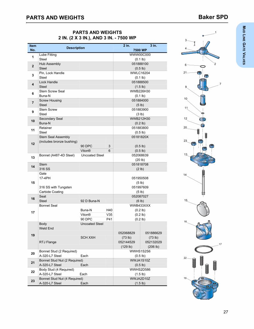
PARTS AND WEIGHTS2 IN. (2 X 3 IN.), AND 3 IN. - 7500 WP
ItemNo. Description 2 in. 3 in.
7500 WP
1 000C00WWW gnittiF ebuL)bl 1.0(leetS
2 Hub Assembly 051888100Steel (0.5 lb)
3 40261CLWWeldnaH kcoL ,niP)bl 1.0(leetS
4 Lock Handle 051888500Steel (1.5 lb)
6 03H622BWWlaeS wercS metS)bl 1.0(N-anuB
7 Screw Housing 051884000Steel (5 lb)
9 009388150wercS metS)bl 3(leetS
10 Secondary Seal WWB212H30Buna-N (0.2 lb)
11 008388150reniateR)bl 5.0(leetS
12
Stem Seal Assembly 05181820X(includes bronze bushing)
90 DPC 3 (0.5 lb)Viton® 6 (0.5 lb)
13 Bonnet (A487-4D Steel) Uncoated Steel 052068639(20 lb)
14 Stem 051818708316 SS (2 lb)
15
Gate805059150HP4-71
(5 lb)906799150netsgnuT htiw SS 613
)bl 5(gnitaoC edibraC
16 Seat 052087027Steel 92 D Buna-N (6 lb)
17
XXX334BWWlaeS tennoBBuna-N H40 (0.2 lb)Viton® V35 (0.2 lb)90 DPC P41 (0.2 lb)
19
Body Uncoated SteelWeld End
052068829 051886629SCH XXH (73 lb) (73 lb)
RTJ Flange 052144529 052132029(129 lb) (206 lb)
20 6S2S1SHWW)deriuqeR 2( dutS tennoB)bI 5.0(hcaE leetS 7L-023-A
21 Bonnet Stud Nut (2 Required) WWJA1S10ZA-320-L7 Steel Each (0.5 lb)
22 685D2SHWW)deriuqeR 4( dutS ydoB)bl 5.1(hcaEleetS 7L-023-A
23 Bonnet Stud Nut (4 Required) WWJA2D10ZA-320-L7 Steel Each (1.5 lb)
1
4
21
3
9
10
11
12
16
15
13
14
19
17
22
6
7
23
2
20
PARTS AND WEIGHTSM
UD L
INE G
ATE V
ALVES

Baker SPD
29
PARTS AND WEIGHTS4 IN. AND 5 X 4 IN. - 7500 WP
Item No. Description
4 in. 5 x 4 in.7500 WP
1000C00WWW gnittiF ebuL
)bl 1.0(leetS
2Handle Assembly 051888300Steel (0.5 lb)
3006988150ebuT
)bl 2.0(cilyrcA raelC
4Stem Cap 051889700Ductile Iron (2.5 lb)
5000A00WWWyeK
)bl 5.0(leetS
6Stem Screw 051883200Steel (5 lb)
703H622BWWlaeS wercS metS
70 D Buna-N H30 (0.1 lb)70 D Viton® V40 (0.1 lb)
8Screw Housing 051883400Steel (8 lb)
9802028150metS
)bl 3(leetS sselniatS 613
10Secondary Seal WWB214H40
90 D Buna-N H40 (0.2 lb)90 D Viton® V40 (0.2 lb)
11008288150reniateR
)bl 1(leetS
12
Stem Seal Assembly 05181950X(includes bronze bushing)
90 DPC 3 (0.5 lb)90 D Viton® 6 (0.5 lb)
13000388150)deriuqeR 2( gniraeB
)bl 1.0(hcaEcilonehP/®nolfeT
14Down Stop Ring 051882900303 Stainless Steel (0.5 lb)
16935988150leetS detaocnU)leetS 784-A( tennoB
(61 lb)
18
Bonnet Seal WWB439XXX90 D Buna-N H40 (0.2 lb)98 D Viton® V40 (0.2 lb)90 DPC P41 (0.2 lb)
19
Gate907799150HP4-71
(9 lb)906670250 netsgnuT htiw leetS sselniatS 613
)bl 9(sgnitaoC edibraC
20Body Uncoated SteelWeld SCH XXH 052076329 051999429
(134 lb) (134 lb)
21725028150taeS
)bl 92(N-anuB D 29leetS
23Bonnet Stud (2 Required) WWHS1W3H6A-320-L7 Steel Each (1.5 Ib)
24Z01W1AJWW)deriuqeR 2( tuN dutS tennoB
)bI 5.1(hcaE leetS 7L-023-A
25Body Stud (4 Required) WWHS2S606A-320-L7 Steel Each (0.5 lb)
26Z01S2AJWW)deriuqeR 4( tuN dutS ydoB
(2 lb)
1
4
24
3
13
10
11
12
21
19
9
14
20
18
25
6
8
16
2
26
23
5
13
7
PARTS AND WEIGHTSM
UD L
INE G
ATE V
ALVES

Baker SPD
31
PARTS AND WEIGHTS5-1/8 IN. AND 6 X 5-1/8 IN. - 7500 WP
Item No. Description
5-1/8 in. 6 x 5-1/8 in.7500 WP
1922411250 ydoB 052114129
degnalFleetS XXH543 280
2Seat 052115300410 Stainless Steel 92 D Buna-N (8 lb)
3001511250gniR raeW
)bl 5(taoC lekciN/leetS yollA
4O-ring Seal WWB435P41Buna-N 90 DPC (0.10 lb)
5Gate 05211529017-4 PH (20 lb)
6Gate Clip 052115700Stainless Steel (0.10 lb)
7Stem 052115400
)bl 7(leetS sselniatS 014
8Bonnet Seal WWB446XXX
90 D Buna-N P41 (0.1 lb)90 D Viton® V40 (0.1 lb)
9920411250)leetS 784-A( tennoB
)bl 311(enoN:sgnitaoC10 Stem Seal Assembly 052116303
Thru 90 DPC 3 (0.25 lb)14 90 D Viton® 6 (0.25 lb)
15XXX812BWWlaeS gnir-O
90 DPC P41 (0.10 lb)90 D Viton® V40 (0.10 lb)
16Body Stud (12 Required) WWHS24506A-320-L7 Steel (1.25 lb)
17Z0442BJWW)deriuqeR 21(tuN dutS ydoB
)bl 55.0( leetS L7-491-A
18Packing Retainer 052115500Steel (7.5 lb)
190175SAEWW)deriuqeR 4(rehsaW tsurhT
Steel (0.5 lb)
20Needle Thrust Bearing (2 Required) WWEAXK751Steel (0.15 lb)
21006511250gnisuoH wercS
Steel (14 lb)
22Socket Hex Head Cap Screw (4 Required) WWG11M1S0
(.20 lb)
2303H433BWWlaeS gnir-O
(.10 lb)
24Lube Fitting WWW00C000Steel (0.1 lb)
25009511250paC tennoB
Steel (11.5 lb)
26Bonnet Hex Head Cap Screw (4 Required) WWG31S508A-194-2H Steel Each (.20 lb)
27000511250wercS gnikcoL leehwdnaH
(.25 lb)
28O-ring Seal WWB111H30
(.10 lb)
290B5411250leehwdnaH
Steel (26 lb)
30Tube 052114900Clear Acrylic (.25 lb)
310B8411250paC metS
)bl 8(leetS nobraCN/A = Not Available.
31
30
29
26
25
23
19
19
22
21
19
17
16
14
13, 12, 11, 10
9
54
3
21
4
3
6
7
8
15
18
20
20
24
242728
PARTS AND WEIGHTSM
UD L
INE G
ATE V
ALVES

Baker SPD
32
2 IN. - 2000 WP, 3000 WP, AND 5000 WP GATE VALVETOOLS REQUIRED FOR ASSEMBLY• Hammer and mandrel or metal bar • Grinder with flapper wheel• •tib 44# dna llirD Pressure test facility and fixtures• •hcnerw epip elbatsujdA 5/16 in. Nut Driver• Torque, impact or socket wrench and socket • Vise Grips• Grease gun and grease, molybdenum disulfide base
a. Slide the threaded end of the Stem (14) throughthe Bonnet Bore (13), from the underside andplace the Stem Seal Assembly (12) over theStem. This assembly consists of the Seal Rings, aflat-backed follower ring and a Bushing, which areplaced over the end of the Stem in that order.Slide the Retainer (11) with an O-ring Seal (10) in-side, over the Stem. Observe that the lips of the O-ring Seal do not get curled back. Seat the StemSeal Assembly into its counterbore in the Bonnet.
b. Engage the Stem Screw (9) in the Screw Housing(7) about half its total travel and place the ScrewHousing on the Bonnet and Stem.
c. Using vice grips, attach to Tee-Head of Stem,then rotate clockwise until Stem is above lugs sothe gate can be attached. Remove vice grips andattach gate to Tee-Head. Rotate the gate to theopening between the lugs. Place the assembly onits side with the lock set screw facing up and usingthe lock set screw as a marker, turn counter clock-wise three times at 360° each.
d. Install lock screw, tighten, and then install the seatonto the gate. Install the Bonnet seal and Item No.pin into the body. Grease the outside of the seatand the inside of the body. Install the Bonnet as-sembly into the body. Install the coupling over theBonnet and tighten onto the body with a pipewrench. Install the handle hub on the Stem Screw
and insert the lock handle retainer lock with thelock handle pin. Do not spread the cotter pin at thistime. Close the gate valve until the hub is restingon the top of the Screw Housing. At this point,mark the gate with a pencil at the bottom of theseat bore. Raise the bottom of the gate by turningthe handle counter clockwise until half open. Mea-sure the mark on the gate to verify the gate is fullydown at 5/16 in. to 7/16 in. If the distance is cor-rect, then fully open the gate valve, spread thecotter and insert the drift bar pin. If correct, go tostep F.
e. If not correct, then remove the handle and cou-pling from Bonnet assembly. Remove Bonnet as-sembly from the body. Remove the lock screwfrom the Stem Screw Housing and adjust the tim-ing by rotating the Stem Screw clockwise to in-crease distances or counter clockwise todecrease distances. Repeat step D.
f. When the Baker Mud Gate Valve is assembled inthe manner described, the Hub is stopped by theScrew Housing at the proper down position of theGate. By this design, overtightening is impossibleand maximum sealing efficiency is assured.
Note: Refer to pages 14 and 15 for numbered illustra-tion.
ASSEMBLY PROCEDURES
REPAIR INSTRUCTIONS

Baker SPD
33
3 IN., 4 IN., AND 4-1/16 IN. - 2000 WP AND 3000 WP AND 3 IN. - 5000 WP GATE VALVETOOLS REQUIRED FOR ASSEMBLY• Hammer and mandrel or metal bar • Pressure test facility and fixtures• dna nug esaerG •tiB llirD 44# htiw llirD grease, molybdenum disulfide base• leehw reppalf htiw rednirG •hcnerw epip elbatsujda IPA• Torque, impact or socket wrench and socket • 5/16 in. Nut Driver• spirG esiV •revirdwercS
a. Slide the threaded end of the Stem (14) throughthe Bonnet Bore (13) from the underside andplace the Stem Seal Assembly (12) over theStem. This assembly consists of the Seal Rings, aflat-backed follower Ring and a Bushing which areplaced over the end of the Stem in that order.Slide the Retainer (11) with O-ring Seal (10) insideover the Stem. Observe that the lips of the Ring donot get curled back. Seat the Stem Seal Assemblyinto its counterbore in the Bonnet. Install BonnetStuds (20).
b. Engage the Stem Screw (9) in the Screw Housing(7) about half [1/2] its total travel and place theScrew Housing on the Bonnet and Stem. ReplaceNuts (21).
c. Rotate the Stem Screw clockwise until it bottomson the Retainer, then back it up approximately 45degrees. Engage the Gate (15) on the Tee-Headof the Stem and turn them together counter clock-wise until the Gate touches the underside of theBonnet Lugs. Align the Gate with the opening be-tween the Lugs and retract it into the Bonnet byturning the Stem Screw counter clockwise. Placethe Hub (2) on the Stem Screw, insert the LockHandle (4), and retain it with the Lock Handle Pin(3).
ASSEMBLY AND TIMING PROCEDURESd. Install the Seat (16) onto the Gate and grease the
outside of the seat. Install Body Studs and BonnetSeal, then grease the inside of the Body. Installthe Bonnet assembly into the Body. Place StudNuts and tighten per appropriate torque. Close thegate fully by turning the handle clockwise. Makesure the Hub Assembly sits flush on the ScrewHousing. Also, make pencil marks on the Gateeven with the bottom of the Seat Bore. Open thegate by turning the handle counter clockwise andmeasure distance from mark to the bottom of theGate. This distance should fall within the followinglimits for each valve size:
If either the distance is not correct, or the Hub isnot flush with the Screw Housing, open the gatefully, loosen the Bonnet Stud Nuts and remove.Turn the handle clockwise while raising the StemScrew Assembly above the Bonnet Studs. Turnthe Stem Screw assembly clockwise or counterclockwise, as appropriate to correct timing. Turnthe handle counter clockwise to lower the StemScrew Assembly back down on the retainer. Re-place the Nuts and hand tighten. Recheck thegate timing. If still not timed, repeat timing pro-cess. If timing is correct, tighten the Bonnet Nutsto appropriate torque.
e. When the Baker Gate Valve is assembled in themanner described, the Hub is stopped by theScrew Housing at the proper down position of theGate. By this design, overtightening is impossibleand maximum sealing efficiency is assured.
Note: Refer to pages 16, 17, 18, and 19 for numbered illustration.
3 in. 4 in.3/8 in. - 1/2 in. 7/16 in. - 9/16 in.
Stud Diameter Torquein. ft-lbf1/2 605/8 893/4 1077/8 1621 244
1-1/8 3221-1/4 4101-3/8 5101-1/2 615
ASSEMBLY PROCEDURES
REPAIR INSTRUCTIONSM
UD L
INE G
ATE V
ALVES

Baker SPD
34
4 IN., 4-1/16 IN., 5 X 4 IN., AND 6 X 4 IN. - 5000 WP GATE VALVETOOLS REQUIRED FOR ASSEMBLY• Hammer and mandrel or metal bar • Pressure test facility and fixtures
a nug esaerG •tiB llirD 44# htiw llirD • nd grease, molybdenum disulfide baseleehw reppalf htiw rednirG •hcnerw epip elbatsujdA •
• Torque, impact or socket wrench and socket • 5/16 in. Nut DriverspirG esiV •revirdwercS •
a. Slide the threaded end of the Stem (9) through theBonnet Bore (16), from the underside and drawthe Stem Head part way up into the Bonnet. Putthe Down Stop Ring (14) over the bottom of theStem Head. Lower the Stem so that the DownStop Ring shoulders on the inside of the Bonnetand slide the Gate (19) onto the Tee-Head of theStem.
b. Place the Stem Seal Assembly (12) over theStem. This assembly consists of three [3] SealRings, a flat backed follower ring and a Bushingwhich are placed over the end of the Stem in thatorder. Carefully work down the Seal and followerover the Stem threads. Observe that the lips of thering do not get curled back. After the Bushing,place the Retainer (11) with O-ring Seal (10) downover the Stem with flat side up.
c. Follow the Retainer with a Bearing (13) and theStem Screw (6). Note that the Bearing must beconcentric with the Stem Screw before further as-sembly. It can be held in place by turning the StemScrew counter clockwise until the Stem Headseats against the Bonnet. Place another Bearingdown over the Stem Screw and follow it with theScrew Housing (8), with O-ring Seal (7) inside,and tighten Nuts (24). Place the Key (5) into itsslot in the Stem Screw and replace the Handle (2),Tube (3), and Stem Cap (4) in that order.
d. Slide the Gate (19) onto the Stem, turn it onequarter of a turn, to line it up with the slot in theBonnet and draw it up all the way into the Bonnetby turning the Handle counter clockwise. Replacethe Bonnet Seal (18) and install Seat and BonnetAssembly in the body. Tighten Nuts (26) pertorque requirement, and repack the Screw Hous-ing (8) with general purpose grease through Fit-ting (1).
Note: Refer to pages 20 and 21 for numbered illustra-tion.
StudDiameter Torque
in. ft-lbf1/2 605/8 893/4 1077/8 1621 244
1-1/8 3221-1/4 4101-3/8 5101-1/2 6151-3/4 830
REPAIR INSTRUCTIONS
ASSEMBLY PROCEDURES

Baker SPD
35
2 IN. (2 X 3 IN.), AND 3 IN. - 7500 WP GATE VALVETOOLS REQUIRED FOR ASSEMBLY• Hammer and mandrel or metal bar • Pressure test facility and fixtures• •tiB llirD 44# htiw llirD Grease gun and grease, molybdenum disulfide base• •hcnerw epip elbatsujda IPA Grinder with flapper wheel• Torque, impact or socket wrench and socket • 5/16 in. Nut Driver• •revirdwercS Vise Grips
ASSEMBLY PROCEDURESa. Slide the threaded end of the Stem (14) through the
Bonnet Bore from the underside and place theStem Seal Assembly (12) over the Stem. This as-sembly consists of the Seal Rings, a flat-backed fol-lower Ring, and a Bushing which are placed overthe end of the Stem in that order. Slide the Retainer(11) with O-ring Seal (10) inside of the Stem. Ob-serve that the lips of the ring do not get curled back.Set the Stem Seal Assembly into its counterbore inthe Bonnet. Install Bonnet Studs (20).
b. Engage the Stem Screw (9) in the Screw Housing(7) about half (1/2) its total travel and place theScrew Housing on the Bonnet and Stem. ReplaceNuts (21).
c. Rotate the Stem Screw clockwise until it bottoms onthe Retainer, then back it up approximately 45 de-grees. Engage the Gate (15) on the Tee-Head ofthe Stem and turn them together counter clockwiseuntil the Gate touches the underside of the BonnetLugs. Align the Gate with the opening between theLugs and retract it into the Bonnet by turning theStem Screw counter clockwise. Place the Hub (2)on the Stem Screw, insert the Lock Handle (4), andretain it with the Lock Handle Pin (3).
ASSEMBLY AND TIMING PROCEDUREd. Install the Seat (16) onto the Gate and grease the
outside of the Seat. Install Body Studs and Bonneton Seat and Valve Body, then lubricate the inside ofthe Body. Note: Use a mixture of 25% Dixon #635 LubricationFlake Graphite and 75% 10 weight oil for lubricationon Seat and Valve Body Bore prior to installing Seatinto Body).
e. Install the bonnet assembly into the Body. ReplaceBody Nut and tighten per appropriate torque. Closethe Gate fully by turning the handle clockwise.Make sure the Hub sits flush on the Screw Housing.Also, make pencil marks on the Gate even with thebottom of the Seat Bore. Open the Gate by turningthe handle counter clockwise and measure dis-tance from mark to the bottom of the Gate. This dis-tance should fall within the following limits: (3/8 in. - 1/2 in.)
f. If either the distance is off, or the Hub is not flushwith the Screw Housing, open the Gate fully, loosenthe Bonnet Nut and remove. Turn the handle clock-wise while raising the Stem Screw Assembly abovethe Bonnet Studs. Turn the Stem Screw Assemblyclockwise or counter clockwise, as appropriate tocorrect timing. Turn the handle counter clockwise tolower the Stem Screw Assembly back down on theRetainer. Replace the Nuts and hand tighten, re-check the gate timing. If still not timed, repeat timingprocess. If timing is correct, tighten the bonnet nutsto appropriate torque and forward to the testingarea.
g. When the Baker Gate Valve is assembled in themanner described, the Hub is stopped by the ScrewHousing at the proper down position of the Gate. Bythis design, overtightening is impossible and maxi-mum sealing efficiency is assured.
Note: Refer to pages 26 and 27 for numbered illustra-tions.
Stud Diameter Torquein. ft-lbf1/2 605/8 893/4 1077/8 1621 244
1-1/8 3221-1/4 4101-3/8 5101-1/2 615
REPAIR INSTRUCTIONSM
UD L
INE G
ATE V
ALVES

Baker SPD
36
4 IN. AND 5 X 4 IN. - 7500 WP GATE VALVETOOLS REQUIRED FOR ASSEMBLY• Hammer and mandrel or metal bar • Grinder with flapper wheel
•tiB llirD 44# htiw llirD • Pressure test facility and fixtures• •hcnerw epip elbatsujdA 5/16 in. Nut Driver• Torque, impact or socket wrench and socket • Vise Grips• Grease gun and grease, molybdenum disulfide base • Screwdriver
ASSEMBLY PROCEDURESa. Slide the threaded end of the Stem (9) through the
Bonnet (16) bore, from the underside of the Bonnet,until the Tee Slot on the Stem is half way into theBonnet Cavity.
b. Slide the Down Stop Ring (14) over the Tee Slot ofthe Stem and then lower the Stem until the DownStop Ring shoulders on the Bonnet.
c. Slide the Gate (19) onto the Tee Slot of the Stem,align with Bonnet slot and raise the Stem/Gate as-sembly into the Bonnet until it tops-out.
d. Place Stem Seal Assembly (12) over the threadedpart of the Stem. The assembly consists of three [3]Seal Rings, a flat-backed follower ring and a bush-ing.Note: Carefully work the seals over the Stemthreads making sure the seals do not tear or curl.
e. After the bushing, place Secondary (O-ring) Seal(10) into the Retainer (11) and slide onto the Stemso that it rests on the bushing.
f. Place a Bearing (13) on top of the retainer.g. Thread Stem Screw (6) onto the Stem until the
Stem Screw bottoms-out on the bearing and theGate is completely topped-out in the Bonnet cavity.
h. Place another bearing (13) over the Stem Screw.i. Place Stem Screw (O-ring) Seal (7) into the Screw
Housing (8). Put Screw Housing over the StemScrew aligning on the Bonnet Studs (23).
j. Tighten Bonnet Stud Nuts (24) on the Bonnet Studsto hold the Screw Housing in place.
k. Place Key (5) into its slot in Stem Screw, put on theHandle Assembly (2), Sight Tube (3), and StemCap (4) in that order.
l. Lower the Gate, by turning handle clockwise, untilthe Stem threads show about one inch in the SightTube.
m. Place Bonnet Seal (18) into Body (20) Groove, andthread the Body Studs (25) into Body.
n. Liberally lubricate Gate. Spread the Seat (21) apartusing the pegs and put the Seat onto the Gate.
o. Slide the Seat onto the Gate until the pegs locateinto the Bonnet holes.
p. Lubricate the outside of the Seat and the inside ofthe Body with mixture of 25% Dixon #635 Lubricat-ing Flake Graphite and 75% 10 Weight Oil.
q. Slide the Seat/Bonnet Assembly into the Bodyabout one to two inches. Raise the Gate until aboutone inch is still in the Seat.
r. Slide the Seat completely into the Body. Make surethat the Seat is going in straight, otherwise the Seatwill tear.
s. Tighten the Body Stud Nuts (26) to the requiredtorque.
t. Lube the Stem with general purpose grease via theLube Fitting (1).
Note: Refer to pages 28 and 29 for numbered illustra-tion.
StudDiameter Torque
in. ft-lbf1/2 605/8 893/4 1077/8 1621 244
1-1/8 3221-1/4 4101-3/8 5101-1/2 6151-3/4 830
REPAIR INSTRUCTIONS
Baker SPD
37
5-1/8 IN., AND 6 X 5-1/8 IN. - 7500 WP GATE VALVETOOLS REQUIRED FOR ASSEMBLY• Impact wrench/torque wrench (capable of 700 ft-lbs) • 5/8 in. Allen Wrench
esaerg htiw nug esaerG •sloot pohs dradnatS •
ASSEMBLY PROCEDURESa. Slide the threaded end of the Stem (7) through the
bore of the Bonnet (9), opposite the stem sealbore.
b. Place the Stem Seal Assembly (10-14) over theStem (7) and install into the stem seal bore (gland)in the Bonnet (9). Install in the following order, withthe chevron side of the seals facing into the stemseal bore:
• Bottom Adapter (10)• Pressure Ring (11)• Seal Ring (12)• Pressure Ring (11)• Top Adapter (13)• Gland Ring (14)
c. Install the O-ring (15) into the Packing Retainer(18) by applying grease to the O-ring groove.Install the Packing Retainer (18) over the Stem (7)and onto the Bonnet (9). Install four [4] SocketHead Cap Screws (22) and fully tighten.
d. Grease two [2] Needle Bearings (20). Place one[1] Thrust Washer (19) onto the Packing Retainer(18) followed by one [1] Needle Bearing (20) andone [1] Thrust Washer (19).
e. Place the Stem Screw Housing (21) onto theThrust Washers (19) and Needle Bearing (20).Insert one [1] Thrust Washer (19) onto the StemScrew Housing (21) followed by one [1] NeedleBearing (20) and one [1] Thrust Washer (19).
f. Install O-ring (23) onto the Stem Screw Housing(21). Install the Bonnet Cap (25) onto the StemScrew Housing (21). Install four [4] Bonnet HexHead Cap Screws (26) through the Bonnet Cap(25), Packing Retainer (18), and into the Bonnet
(9). Fully tighten the Bonnet Hex Head CapScrews (26).
g. Install the Handwheel (29) onto the Stem ScrewHousing (21). Install O-ring (28) onto theHandwheel Locking Screw (27). Install theHandwheel Locking Screw (27) through theHandwheel (29) and into the Stem Screw Housing(21) and fully tighten.
h. Install the Clear Acrylic Tube (30) over the stemthreads. Install the Stem Cap (31) onto the StemScrew Housing (21) and fully tighten.
i. Install the Gate Clip (6) onto the Stem (7). Installthe Gate (5) onto the Stem (7) and bend the tabsof the Gate Clip (6) down and towards the Gate(5).
j. Retract the Stem (7) until it bottoms on the Bonnet(9). Install O-ring (8) onto the Bonnet (9).
k. Install O-ring (4) onto the Wear Ring (3). Repeatfor the second O-ring and wear ring. Install two [2]Wear Rings (3) into the Body (1). Install the Seat(2) into the Wear Rings (3) by collapsing the top ofthe Seat (2), aligning the boss on the Seat (2) withthe bore in the Body (1). Release the Seat (2) andthe Seat (2) will lock into place.
l. Lightly grease the Body Studs (16) and install theBody Studs (16) into the Body (1). Install thebonnet assembly onto the Body (1). Install theBody Stud Nuts (17) onto the Body Studs (16) andtorque to 688 ft-lbs. Torque evenly in a criss-crossfashion.
m. Install the Lube Fittings (24). Apply grease to bothfittings.
Note: Refer to pages 30 and 31 for numbered product illustrations.
REPAIR INSTRUCTIONSM
UD L
INE G
ATE V
ALVES