Embed Size (px)
Citation preview
Document Number: ICT-317669-METIS/D4.1
Project Name: Mobile and wireless communications Enablers for the Twenty-twenty Information Society
(METIS)
Deliverable D4.1
Summary on preliminary trade-off investigations and first set of potential network-level solutions
Date of delivery: 30-09-2013 Revision 1.0 Start date of Project: 01-11-2012 Start date of Project 30-04-2015
Ref. Ares(2014)1067768 - 04/04/2014
METIS Public ii
Deliverable D4.1
Summary on preliminary trade-off investigations and first set of potential network-
level solutions
Project Number: ICT-317669
Project Name: Mobile and wireless communications Enablers for the Twenty-twenty Information Society
Document Number: ICT-317669-METIS/D4.1
Document Title: Summary on preliminary trade-off investigations and first set of potential network-level solutions
Editor(s): Nadia Brahmi (Ericsson AB), Venkatkumar Venkatasubramanian (Nokia Siemens Networks)
Author(s): Osman Aydin, Stefan Valentin (Alcatel-Lucent Bell Labs), Zhe Ren (BMW Group Research and Technology), Tilak Rajesh Lakshmana, Yutao Sui, Tommy Svensson (Chalmers University of Technology), Liang Hu, Emmanuel Ternon, Patrick Agyapong (DOCOMO), Gabor Fodor, Nadia Brahmi (Ericsson AB),Federico Penna, Slawomir Stanczak (Frauenhofer HHI), Ömer Bulakci, Chan Zhou, Josef Eichinger, (Huawei ERC), Panagiotis Spapis, Alex Kaloxylos, Konstantinos Chatzikokolakis, Makis Stamatelatos (National and Kapodistrian University of Athens), Osman Yilmaz (Nokia), Michal Maternia, Venkatkumar Venkatasubramanian, Reza Holakouei, Patrick Marsch (Nokia Siemens Networks), Marcin Rodziewicz, Pawel Sroka (Poznan University of Technology), Jose F. Monserrat, Sonia Giménez (Technical University of Valencia), Luis Cucala Garcia (Telefonica), Ji Lianghai, Nandish Kuruvatti, Andreas Klein (University of Kaiserslautern)
Dissemination Level: PU
Contractual Date of Delivery: 01/10/2013
Status: Public
Version: 1
File Name: METIS_D4.1_v1.docx
METIS Public iii
Abstract:
METIS WP4 covers research activities in network-level aspects of the advancement of wireless network technologies towards the year 2020 and beyond. The aim is to develop novel network-level technology concepts to address the challenges foreseen in future scenarios with regard to interference, traffic and mobility management issues. Moreover, another task of this work package is to propose functional enablers which can support the above potential solutions.
This document provides
a report of the ongoing progress in WP4 regarding the research topics agreed upon in IR 4.1,
a high level description of the proposed concepts and approaches adopted by different partners.
More specifically, the document describes, first set of potential network-level solutions and presents some first research results in order to position them with regards to the state of the art approaches. It also gives an overview of research activities to be considered later in WP4.
Keywords:
Interference estimation, mode selection, power control, phantom cell, trajectory prediction, D2D, Ultra Dense Network, Multi-RAT network, service mapping, context awareness, handover, clustering, moving cells, METIS
Document: FP7-ICT-317669-METIS/D4.1
Date: 04/04/2014 Security: Public
Status: Final Version: 1
METIS Public iv
Executive summary
This document organizes the research work covered in METIS Work Package 4 (WP4) with the aim of providing novel network-level concepts to address the challenges predicted in wireless network for year 2020 and beyond. More precisely, we look into efficient deployment, operation and optimization of the sophisticated multi-layer and multi-RAT networks expected in future systems. The research activities in WP4 are divided into three main tasks: T4.1 dealing with the co-existence between multiple layers and multiple RATs, cluster-based collaboration and interference management, T4.2 for the management of demand, traffic and mobility, and T4.3 for functional network enablers.
For the organization of the research work, based on partners core competencies, we have identified, within each of the main tasks, core research topics and grouped them into sub-tasks (i.e. research activities with the same project high level-scope). Each sub-task is further split into one or several technology components which address a specific problem through one or several approaches at an algorithmic level. The proposed technology components and their technical solutions aim to fulfill the METIS objectives in various deployment scenarios. Based on state-of-the-art analysis, the existing solutions for the technology components were studied and will be used for comparison during the course of the project. The technology components are envisioned as network level building blocks that will help creating an energy efficient and cost conscious system concept that, relative to today, will support
1000 times higher mobile data volume per area,
10 times to 100 times higher number of connected devices,
10 times to 100 times higher typical user data rate,
10 times longer battery life for low power Massive Machine Communication devices,
5 times reduced End-to-End latency.
Some of the Technology Components are designed to enable a further evolution of modern networks towards 5G, while others introduce disruptive solutions for a revolutionary form of future 5G systems. Each technology component is designed to fulfill at least one of the METIS objectives. At this stage of the project, most investigated concepts in WP4 are tailored towards three cross-work package topics of METIS: Device-to-device (D2D), Ultra Dense Networks (UDN) and moving networks (MN).
T4.1 activities are further organized into three sub-tasks: interference identification techniques which provide ways to reliably predict future interference events relevant for the two remaining activities namely, smart and coordinated resource usage and clustering for cooperation
T4.2 is organized into two main sub-tasks: smart device/service to RAT/layer mapping, where a variety of context information collected from the user’s environment, the devices, the services etc., is exploited to optimize the resource mapping in a multi-layer and multi-RAT environment, and smart signaling for mobility, which investigates mobility related signaling and explores the use of context information for enhancing the handovers decision making.
T4.3 aims at providing network enablers for interference, traffic and mobility management solutions proposed in T4.1 and T4.2. Based on METIS needs analysis we intend to identify new management interfaces for efficient information fusion and management of the network. Moreover, solutions for dynamic configuration of the network through automatic-integration (auto-integration) and self-management are investigated to provide the desired capacity increase.
Document: FP7-ICT-317669-METIS/D4.1
Date: 04/04/2014 Security: Public
Status: Final Version: 1
METIS Public v
Contents 1 Introduction ......................................................................................................................... 1 2 Co-existence, collaboration and interference management ................................................ 3
2.1 Interference identification ............................................................................................. 3 2.1.1 State-of-the-art ...................................................................................................... 4 2.1.2 Technology Component 1: New interference estimation techniques .................... 4
a) Adaptive Projected Sub-gradient Method (APSM) ................................................... 4 b) Minimum Mean Square Error (MMSE) Estimation ................................................... 6
2.2 Smart and coordinated resource usage ....................................................................... 7 2.2.1 Smart and coordinated resource usage for D2D .................................................. 7
2.2.1.1 Device discovery ........................................................................................... 8 2.2.1.1.1 Literature review ........................................................................................ 8 2.2.1.1.2 Device discovery research ......................................................................... 8 2.2.1.1.3 Technology Component 2: Unified Solution for Device Discovery ............. 9
2.2.1.2 D2D communications .................................................................................. 10 2.2.1.2.1 Literature review ...................................................................................... 10 2.2.1.2.2 Technology Component 3: Novel mode selection schemes for D2D ....... 11 2.2.1.2.3 Technology Component 4: New methods for D2D Resource Allocation . 13 2.2.1.2.4 Technology Component 5: Methods for Power Control and SINR target Setting for D2D .......................................................................................................... 16 2.2.1.2.5 Results for CSI-based mode selection and power control algorithms ..... 20
2.2.2 Smart and coordinated resource usage in UDN ................................................. 21 2.2.2.1 State-of-the-art ............................................................................................ 22 2.2.2.2 Technology Component 6: Centralized schemes for interference management in UDN ..................................................................................................... 23 2.2.2.3 Initial results on coordinated fast uplink downlink resource allocation in UDN 28 2.2.2.4 Technology Component 7: Decentralized and hybrid Schemes for Interference Management in UDN ................................................................................. 29
2.2.3 Interference management in Moving Networks (MN) ......................................... 32 3 Demand, traffic, and mobility management ....................................................................... 34
3.1 Building context awareness ....................................................................................... 34 3.1.1 State-of-the-art .................................................................................................... 34 3.1.2 Definition and taxonomy of context information .................................................. 35 3.1.3 Technology Component 1: Optimized distribution scheme for context information between the network entities............................................................................................. 35 3.1.4 Prediction methods for context information ........................................................ 36
3.1.4.1 Prediction of user movements based on context and statistics ................... 37 3.1.4.1.1 State-of-the-art ......................................................................................... 37 3.1.4.1.2 Technology Component 2: Context awareness through prediction of next cell 37
3.2 Smart device/service to RAT/layer mapping .............................................................. 39 3.2.1 State of the Art .................................................................................................... 39 3.2.2 Technology Component 3: Smart device/service to layer mapping in the Phantom cell concept ........................................................................................................ 40 3.2.3 Technology Component 4: Efficient Service to layer mapping and connectivity in UDN 41
3.2.3.1 Technology Component 5: Efficient vertical RAT mapping through vertical handover 43
3.3 Smart mobility management ...................................................................................... 46 3.3.1 State-of-the-art .................................................................................................... 46
3.3.1.1 Cell handover optimization .......................................................................... 46 3.3.2 Context-aware handover optimization ................................................................ 47
Document: FP7-ICT-317669-METIS/D4.1
Date: 04/04/2014 Security: Public
Status: Final Version: 1
METIS Public vi
3.3.2.1 Technology Component 6: handover optimization using street-specific context information ........................................................................................................ 47 3.3.2.2 Technology component 7: Context aware mobility handover optimization using Fuzzy Q-Learning ................................................................................................ 48 3.3.2.3 Technology Component 8: D2D handover schemes for mobility management.................................................................................................................. 49
3.3.3 Technology component 9: Smart mobility and resource allocation mapping using context information ............................................................................................................ 50 3.3.4 Technology component 10: Signaling for trajectory prediction ........................... 52
4 Functional Network Enablers ............................................................................................ 53 4.1 New management interfaces ..................................................................................... 53
4.1.1 State of the art analysis for METIS needs .......................................................... 53 4.1.2 Management Interface between Service Providers and Operators .................... 56
4.2 Auto-integration and self-management ...................................................................... 57 4.2.1 Activation and deactivation of nomadic cells ...................................................... 57 4.2.2 Clustering mechanisms ...................................................................................... 58 4.2.3 Clustering toolbox ............................................................................................... 59 4.2.4 Self-management enabled by central database for energy savings in the Phantom Cell Concept (PCC) ........................................................................................... 59
5 Conclusion ........................................................................................................................ 60 6 References ........................................................................................................................ 62 7 Annex – Details of algorithms ........................................................................................... 69
7.1 Mathematical modeling of interference identification ................................................. 69 7.2 Pseudo-codes for Mode Selection, SINR target Setting and Power Control for D2D algorithms ............................................................................................................................. 71 7.3 General cost minimization function for the exchange of context information ............. 75 7.4 Comparison of Prediction Approaches ...................................................................... 76 7.5 UDN Network-assisted connectivity management flowchart ..................................... 78 7.6 Pseudo-code and Mathematical Framework for Fuzzy Q-learning Scheme with results 80
7.6.1 Fuzzy Q learning description .............................................................................. 80 7.6.2 Fuzzy Q learning Results .................................................................................... 81
7.7 Flowchart of D2D-triggered handover ........................................................................ 83 7.8 Description of Smart mobility and resource allocation mapping based on context information (PRA-VDmin) ..................................................................................................... 83 7.9 Experimental validation of clustering mechanisms .................................................... 84
8 Annex 2 - Mapping of Technology Components to METIS goals and Test Cases ........... 86
Document: FP7-ICT-317669-METIS/D4.1
Date: 04/04/2014 Security: Public
Status: Final Version: 1
METIS Public vii
List of Tables
Table 2-1. T4.1 Technology Component 1- Algorithm 1. ........................................................... 5
Table 2-2. T4.1 Technology Component 1- Algorithm 2. ........................................................... 6
Table 2-3. Comparison of D2D Discovery Solutions. ................................................................. 9
Table 2-4. T4.1 Technology Component 2. ................................................................................ 9
Table 2-5. T4.1 Technology Component 3 – Approach 1. ....................................................... 12
Table 2-6. T4.1 Technology Component 3 – Approach 2. ....................................................... 13
Table 2-7. T4.1 Technology Component 4 – Approach 1. ....................................................... 14
Table 2-8. T4.1 Technology Component 4 – Approach 2. ....................................................... 15
Table 2-9. T4.1 Technology Component 4 – Approach 3. ....................................................... 15
Table 2-10. T4.1 Technology Component 4 – Approach 4. ..................................................... 16
Table 2-11. T4.1 Technology Component 5 – Approach 1. ..................................................... 17
Table 2-12. T4.1 Technology Component 5 – Approach 2. ..................................................... 18
Table 2-13. T4.1 Technology Component 5 – Approach 3. ..................................................... 19
Table 2-14. Centralized and decentralized algorithms for interference management. ............. 23
Table 2-15. T4.1 Technology Component 6 – Approach 1. ..................................................... 24
Table 2-16. T4.1 Technology Component 6 – Approach 2. ..................................................... 25
Table 2-17. T4.1 Technology Component 6 – Approach 3. ..................................................... 26
Table 2-18. Technology Component 6 – Approach 4. .............................................................. 27
Table 2-19. T4.1 Technology Component 6 – Approach 5. ..................................................... 27
Table 2-20. T4.1 Technology Component 7 – Approach 1. ..................................................... 30
Table 2-21. T4.1 Technology Component 7 – Approach 2. ..................................................... 31
Table 2-22. T4.1 Technology Component 8. ............................................................................ 33
Table 3-1. T4.2 Technology Component 1. .............................................................................. 36
Table 3-2. T4.2 Technology Component 2. .............................................................................. 38
Table 3-3. T4.2 Technology Component 3. .............................................................................. 40
Table 3-4. T4.2 Technology Component 4 – Approach 1. ....................................................... 42
Table 3-5. T4.2 Technology Component 4 – Approach 2. ....................................................... 42
Table 3-6. T4.2 Technology Component 4 – Approach 3. ....................................................... 43
Table 3-7. T4.2 Technology Component 5 - Approach 1. ........................................................ 44
Table 3-8. T4.2 Technology Component 5 - Approach 2. ........................................................ 45
Table 3-9. T4.2 Technology Component 6. .............................................................................. 47
Table 3-10. T4.2 Technology Component 7. ............................................................................ 48
Table 3-11. T4.2 Technology Component 8 – Approach 1. ..................................................... 49
Table 3-12. T4.2 Technology Component 8 – Approach 2. ..................................................... 49
Table 3-13. T4.2 Technology Component 9. ............................................................................ 50
Document: FP7-ICT-317669-METIS/D4.1
Date: 04/04/2014 Security: Public
Status: Final Version: 1
METIS Public viii
Table 3-14. T4.2 Technology Component 10. .......................................................................... 52
Table 4-1. Summary of Initiatives that have been specifying management interfaces. ........... 54
Table 4-2. New management interface between Service Providers and Operators. ............... 56
Table 4-3. Auto-integration with activation and deactivation of nomadic cells. ........................ 57
Table 4-4. Summary of the clustering toolbox. ......................................................................... 59
Table 4-5. Self-management enabled by central database for energy savings in the Phantom Cell Concept. ............................................................................................................................ 60
Table 7-1. Comparison between clustering mechanisms. ........................................................ 85
Table 7-2. Qualitative analysis of the clustering mechanisms. ................................................. 85
Table 8-1. Mapping between technology components, test cases and METIS Overall goals for T4.1. .................................................................................................................................... 86
Table 8-2. Mapping between technology components, test cases and METIS Overall goals for T4.2. .................................................................................................................................... 87
Document: FP7-ICT-317669-METIS/D4.1
Date: 04/04/2014 Security: Public
Status: Final Version: 1
METIS Public ix
List of Abbreviations, Acronyms, and Definitions
3GPP 3rd Generation Partnership Project
ABS Almost Blank Subframe
ACF Access Control Function
APSM Adaptive Projected Subgradient Method
BS Base Station
CAPEX Capital Expenditure
CDI Connected Device Interfacing
CDMA Code Division Multiple Access
CIMI Cloud Infrastructure Management Interface
CoMP Coordinated Multipoint
CQI Channel Quality Indicator
CSI Channel State Information
CSIR CSI at the Receiver
CUE Cellular User
D2D Device-to-Device communication
DCC Detached Cell Concept
D-ICIC Decentralized ICIC
DIM Distributed Interference Management
DLI Downlink Interference
DMTF Distributed Management Task Force
DR Discovery Resource
eICIC Enhanced Inter-Cell Interference Coordination
EM Element Manager
eNB Evolved Node B
ETSI European Telecommunications Standards Institute
E-UTRAN Evolved-UMTS Terrestrial Radio Access Network
FDD Frequency Division Duplex
FDMA Frequency Division Multiple Access
FFR Fractional Frequency Reuse
GANA Generic Autonomic Network Architecture
GP Gaussian Process
GPR Gaussian Process Regression
GPS Global Positioning System
GRACE Game based Resource Allocation in a Competitive Environment
HAC Hierarchical Agglomerative Clustering
HARQ Hybrid ARQ
HeNB Home evolved Node B
HetNet Heterogeneous Network
HII High Interference Indication
IETF Internet Engineering Task Force
ICIC Inter-Cell Interference Coordination
IMS IP Multimedia Subsystem
IOI Interference Overload Indication
IRC Interference Rejection Combining
IRP Integration Reference Point
IRTF Internet Research Task Force
IS Information Service
ISD Inter site distance
JT Joint Transmission
LLMMSE Linearized Log Minimum Mean Square Error
LTE Long Term Evolution
LTE-A Long Term Evolution Advanced
MBR Minimum Bit Rate
MICS Media Independent Command Service
MIES Media Independent Event Service
MIHF Media Independent Handover Function
MIIS Media Independent Information Service
MIMO Multiple-Input Multiple-Output
MMSE Minimum Mean Square Error
MN Moving Networks
MNO Mobile Network Operator
MRN Moving Relay Nodes
MS Mode Selection
NE Network Element
OFDMA Orthogonal Frequency Division Multiple Access
OPEX Operational Expenditure
PLMN Public Land Mobile Network
PoA Point of Attachment
PoS Point of Service
PPHR Ping-Pong Handover Ratio
PRA Predictive Resource Allocation
PRB Physical Resource Block
QoS Quality of Service
NW Network
RAN Radio Access Network
RAT Radio Access Technology
RB Resource Block
RG Resource Group
RLF Radio Link Failure
RLFR Radio Link Failure Ratio
RNTI Radio Network Temporary Identifier
RNTP Relative Narrowband Transmit Power
RPC Remote Procedure Calls
RRM Radio Resource Management
RSCP Received Signal Code Power
RSRP Reference Signal Received Power
RSSI Received Signal Strength
Indicator
Document: FP7-ICT-317669-METIS/D4.1
Date: 04/04/2014 Security: Public
Status: Final Version: 1
METIS Public x
REST Representational State Transfer
RWP Random Way Point
S3C Service, Capability, Connectivity and Control
SAP Small cell Access Point
SC Small Cell
SCTP Stream Control Transmission Protocol
SFR Soft Frequency Reuse
SIP Session Initiation Protocol
SIR Signal to Interference Ratio
SINR Signal to Interference-and-Noise Ratio
SLA Service Level Agreements
SNR Signal to Noise Ratio
SOA Service Oriented Architecture
SOAP Simple Object Access Protocol
SOCCER Self-Organizing Coalitions for Conflict Evaluation and Resolution
SON Self-Organizing Network
SP Service Providers
TDD Time Division Duplex
TMF TeleManagement Forum
TTT Time to Trigger
UDN Ultra Dense Networks
UDP User Datagram Protocol
UE User Equipment
ULI Uplink Interference
UTRAN Universal Terrestrial Radio Access Network
VCG Vickrey-Clarke-Groves
VD Video Degradation
VHO Vertical Handover
VUE Vehicular User Equipment
VT Vehicular Terminal
VPL Vehicular Penetration Loss
Document: FP7-ICT-317669-METIS/D4.1
Date: 04/04/2014 Security: Public
Status: Final Version: 1
METIS Public 1
1 Introduction
METIS Work Package 4 (WP4) covers research activities in network-level aspects of the advancement of wireless network technologies towards 2020 and beyond. The overall aim is to develop network-level technology concepts which can address the challenges foreseen in future wireless communications. Some of the expected trends are high densification of network nodes requiring interference management, even higher quality of service expectations from users, high mobility of the users, and availability of multiple radio access technologies. This document details the particular research topics that are considered within the broader topics of interference, traffic and mobility management. It gives an overview of initial proposed concepts and network-level solutions to be considered along with first research results illustrating some of the proposed concepts.
In WP4, we have established three main tasks: co-existence, collaboration and interference management (T 4.1), demand, traffic and mobility management (T4.2), and functional network enablers (T4.3). These tasks are split into sub-tasks consisting each of clustered core research topics which are referred to as technology components (TeCs) which will be main drivers of the novel aspects in this work package. A short literature survey of state-of-the-art approaches was done for different respective technology components in order to facilitate a performance comparison of the novel approaches with regards to existing state-of-the-art.
The purpose of this deliverable is to provide
a report of the ongoing progress in WP4 within METIS project
a high level description of proposed concepts and approaches adopted for different technology components in the main section of the document and
details on research algorithms in the appendix
first results on few selected algorithmic approaches
The research activities in this document can be outlined into the following main items:
Task 4.1, coexistence, collaboration and interference management related items, are structured into 2 sub-tasks of interference identification and smart and coordinated resource mapping. In interference identification, we present mathematical modeling of interference identification mechanisms. In smart and coordinated resource mapping sub-task, smart resource allocation schemes are introduced for centralized and distributed interference coordination. These schemes can form a good basis for further trade-off investigation on the degree of centralization which will be conducted in this work package. We note here that in WP4 the term interference management refers to the usage and/or allocation of radio resources on a time-scale of multiple transmission time intervals (TTIs), with special emphasis on network-level key performance indicators (KPIs). Optimization of symbol-level interference management techniques, such as interference alignment or cooperative multi-point is not considered.
Task 4.2 related items on demand, traffic and mobility management, which investigate network-level concepts for a context-aware mapping of devices and services to layers and RATs through 3 sub-tasks: building context-awareness, smart-RAT/layer mapping and smart mobility management. The first sub-task defines the paradigm of context awareness and describes the process of building such awareness in a wireless network. In smart RAT/layer mapping, new concepts such as context based connectivity and Phantom cell layer mapping are presented. For the smart mobility management, concepts such as user initiated vertical handover, smart resource allocation exploiting context information and robust mobility optimization are considered.
Document: FP7-ICT-317669-METIS/D4.1
Date: 04/04/2014 Security: Public
Status: Final Version: 1
METIS Public 2
Task 4.3 related items on functional network enablers. Based on state-of-the-art on proposals for new network management interfaces new interface enablers are discussed for possibilities such as operator to service provider interaction. Then auto-integration and self-management concepts such as nomadic cells and Phantom cell database for energy management are investigated.
The document is structured as follows:
Chapter 2 presents the ongoing research work in T4.1. In section 2.1 interference estimation solutions of adaptive projected sub-gradient and Minimum Mean Square Error (MMSE) estimation, linear log-MMSE estimation for interference estimation are presented. For interference coordination, in section 2.2 an overview of potential representative schemes for a smart and coordinated resource usage for interference management is presented, under a classification based on centralization or distributed functioning. The above mentioned interference coordination schemes are again classified under various horizontal topics such as device-to-device communication, ultra-dense networks and moving networks which can be perceived as technology components for different use cases.
Chapter 3 describes the research activities undergoing in T4.2. In section 3.1 the paradigm of context awareness in a network is introduced, with a proposed framework for exchange of context information. In the same section prediction methods for context information are introduced. In section 3.2, smart device to layer mapping techniques, including better connectivity management in cloud services are also discussed to show the benefit of context awareness. Finally, section 3.3 discusses few techniques to show how the context information can be beneficially exploited for mobility management through new handover optimization algorithms and resource allocation schemes adapted for users in mobility.
Chapter 4 covers T4.3 research activities on enablers and new interfaces to support the solutions proposed in T4.1 and T4.2. We first summarize the state-of-the-art for network management interfaces and identify the METIS needs. In section 4.1 we introduce a novel interface to enhance interaction between operators and service providers. In section 4.2 self-management of nomadic cells and database aided concepts for energy saving are introduced as promising approaches to enable dynamic configuration of the network. Finally, in the same section, potential node clustering mechanisms are summarized.
Document: FP7-ICT-317669-METIS/D4.1
Date: 04/04/2014 Security: Public
Status: Final Version: 1
METIS Public 3
2 Co-existence, collaboration and interference management
This chapter covers research activities conducted in T4.1, co-existence, collaboration and interference management, structured into three main sub-tasks:
Interference identification focuses on efficient schemes for detecting interference, its origin, and a long-term characterisation from a network perspective. That is not only detecting the interference at the physical layer (e.g., received signal power, source location, direction of arrival, etc.), but also mapping the impact of this interference into relevant network KPIs (e.g., radio link failure rate). A reliable prediction of future interference events will be relevant for designing new resource allocation schemes.
Clustering for cooperation deals with the creation of clusters of nodes among which joint interference coordination may take place. The investigated clustering mechanisms are intended to be more general than coordinated multipoint (CoMP) node clustering and include coordination between both devices and network nodes. Research will be conducted on autonomous clustering schemes by focusing on solutions that explicitly consider the trade-off between the gain from the collaboration, the costs for additional infrastructure and feedbacks, such as the degradation due to the feedback loops and the accuracy of channel estimation. Moreover, the self-establishment of hierarchy within such clusters is also studied.
Smart and coordinated resource usage looks into the actual resource allocation among users by exploiting, for example, the information obtained using the mechanisms proposed in the first topic to mitigate the interference and to perform efficient distribution of the network resources.
At this stage of the project, partners have been looking only into interference identification techniques and smart resource allocation schemes. Therefore, no input is provided on clustering and cooperation for interference coordination in this report. The two research topics Interference identification and smart and coordinated resource usage are detailed afterwards through different technology components addressing related challenges.
2.1 Interference identification
Heterogeneous networks were proposed as an alternative/complement to the uniform of densification of the macro-cell layer by deploying additional lower-power nodes (relays, pico- and femto-cells) under the coverage of the macro-cell. These multi-layered networks have gained a significant attention thanks to the improved coverage, capacity, and spectral efficiency they offer compared to traditional macro cellular systems. In order to meet the needs of new scenarios foreseen beyond 2020, the densification of the network with additional low-power network elements of limited capabilities is expected even to increase. In such environments, novel solutions based on interference coordination will play a crucial role in mitigating unexpected strong interference that might occur in specific geographical regions due to the introduction of new communication modes, such as D2D transmissions, or the deployment of low-power nodes that need to coexist with the traditional cellular infrastructure. More precisely, ultra network densification is expected to create complicated and highly non-uniform spatial and temporal interference patterns. Therefore, designing efficient interference coordination schemes that are able to cope with local sources of strong interference will require a reliable knowledge about its spatial distribution provided by novel interference estimation techniques. Furthermore, the prediction of the future interference patterns makes possible the development of proactive network reconfiguration algorithms, which are particularly useful in scenarios with high user mobility.
Document: FP7-ICT-317669-METIS/D4.1
Date: 04/04/2014 Security: Public
Status: Final Version: 1
METIS Public 4
2.1.1 State-of-the-art
Several inter-cell interference management schemes have been proposed in Long Term Evolution Advanced LTE-A under the name of “enhanced inter-cell interference coordination (eICIC)” [LLK+11, WP12, XYY12]. These mechanisms are often targeted towards cell edge users to avoid scheduling the cell-edge terminals of neighboring cells simultaneously. To support such interference coordination, the neighboring eNBs cooperate by exchanging several messages using the X2 interface. These messages provide information about the interference situation and eNB’s scheduling strategies which can be used by the receiving eNBs to enhance the scheduling decisions. For uplink inter-cell interference coordination, a special X2 load indication procedure is used to exchange load information in a proactive or a reactive manner. Two messages are defined: the Interference Overload Indication (IOI), which indicates the uplink interference level experienced on all Resource Blocks (RBs), and the High Interference Indication (HII), which informs about the plans for the uplink transmission. Applied to Radio Resource Management (RRM), this kind of self-organization should allow making a dynamic and automatic optimum coordination of the radio resource utilization among cells in close vicinity sharing the same frequency band, in order to reduce interference and avoid performance loss or service degradation. In the downlink, a bitmap known as Relative Narrowband Transmit Power (RNTP) indicator can be exchanged among eNBs through the X2 interface. This ON-OFF indicator informs the neighbor cells if the eNB intends to transmit on a certain RB with a relative power exceeding a certain threshold value exchanged along with the bitmap. One bit per RB in the frequency domain is sent. The exact value of the upper limit and the periodicity in the reporting are configurable. The RNTP indicator allows eNBs to perform RB scheduling to users according to the interference level introduced by their neighbors. The decision making process followed by eNBs after receiving RNTP indicators is not standardized. An interference management approach based on “cognitive BSs” is suggested in [AKG11]. Other works more closely related to the task of estimation of the interference matrix are presented in [HJC+09], dealing with the estimation of the spatial covariance matrix; and in [EHB08] using a control theory-based approach.
2.1.2 Technology Component 1: New interference estimation techniques
The interference identification methods investigated in T4.1 aim at providing better interference awareness in heterogeneous networks, possibly with underlay D2D communication. They are devised by considering the following challenges:
i) How to identify interfering nodes from the perspective of a single network element (e.g. a D2D capable UE)?
ii) Which measurements are required to reliably estimate the interference structure?
iii) How to incorporate prior information?
In the rest of this section two methods are proposed to estimate the channel gain matrix representing the power gain coefficients from each transmitter to each receiver which describes the downlink interference couplings between all devices.
a) Adaptive Projected Sub-gradient Method (APSM)
This first approach uses an adaptive projection algorithm to estimate/identify long-term interference couplings between Base Stations (BSs) and users. The identified couplings can be utilized while accessing or allocating orthogonal resource blocks to the users. The table below outlines its main foundations.
Document: FP7-ICT-317669-METIS/D4.1
Date: 04/04/2014 Security: Public
Status: Final Version: 1
METIS Public 5
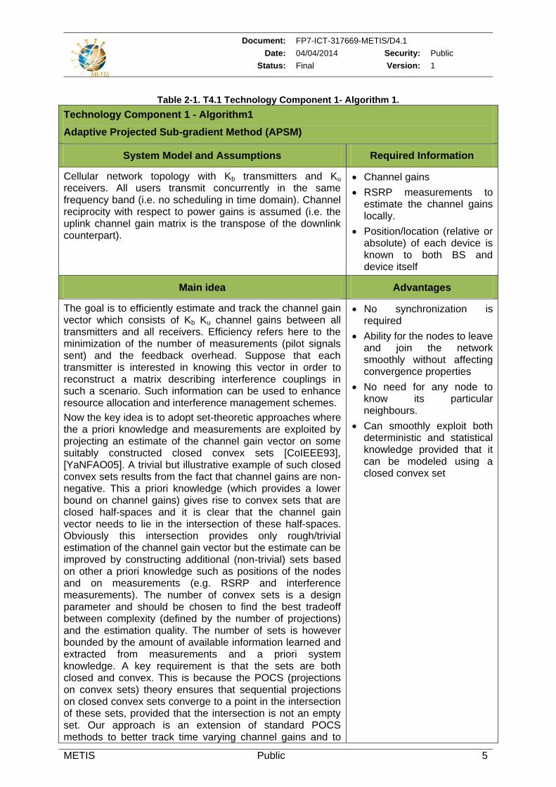
Table 2-1. T4.1 Technology Component 1- Algorithm 1.
Technology Component 1 - Algorithm1
Adaptive Projected Sub-gradient Method (APSM)
System Model and Assumptions Required Information
Cellular network topology with Kb transmitters and Ku receivers. All users transmit concurrently in the same frequency band (i.e. no scheduling in time domain). Channel reciprocity with respect to power gains is assumed (i.e. the uplink channel gain matrix is the transpose of the downlink counterpart).
Channel gains
RSRP measurements to estimate the channel gains locally.
Position/location (relative or absolute) of each device is known to both BS and device itself
Main idea Advantages
The goal is to efficiently estimate and track the channel gain vector which consists of Kb Ku channel gains between all transmitters and all receivers. Efficiency refers here to the minimization of the number of measurements (pilot signals sent) and the feedback overhead. Suppose that each transmitter is interested in knowing this vector in order to reconstruct a matrix describing interference couplings in such a scenario. Such information can be used to enhance resource allocation and interference management schemes.
Now the key idea is to adopt set-theoretic approaches where the a priori knowledge and measurements are exploited by projecting an estimate of the channel gain vector on some suitably constructed closed convex sets [CoIEEE93], [YaNFAO05]. A trivial but illustrative example of such closed convex sets results from the fact that channel gains are non-negative. This a priori knowledge (which provides a lower bound on channel gains) gives rise to convex sets that are closed half-spaces and it is clear that the channel gain vector needs to lie in the intersection of these half-spaces. Obviously this intersection provides only rough/trivial estimation of the channel gain vector but the estimate can be improved by constructing additional (non-trivial) sets based on other a priori knowledge such as positions of the nodes and on measurements (e.g. RSRP and interference measurements). The number of convex sets is a design parameter and should be chosen to find the best tradeoff between complexity (defined by the number of projections) and the estimation quality. The number of sets is however bounded by the amount of available information learned and extracted from measurements and a priori system knowledge. A key requirement is that the sets are both closed and convex. This is because the POCS (projections on convex sets) theory ensures that sequential projections on closed convex sets converge to a point in the intersection of these sets, provided that the intersection is not an empty set. Our approach is an extension of standard POCS methods to better track time varying channel gains and to
No synchronization is required
Ability for the nodes to leave and join the network smoothly without affecting convergence properties
No need for any node to know its particular neighbours.
Can smoothly exploit both deterministic and statistical knowledge provided that it can be modeled using a closed convex set
Document: FP7-ICT-317669-METIS/D4.1
Date: 04/04/2014 Security: Public
Status: Final Version: 1
METIS Public 6
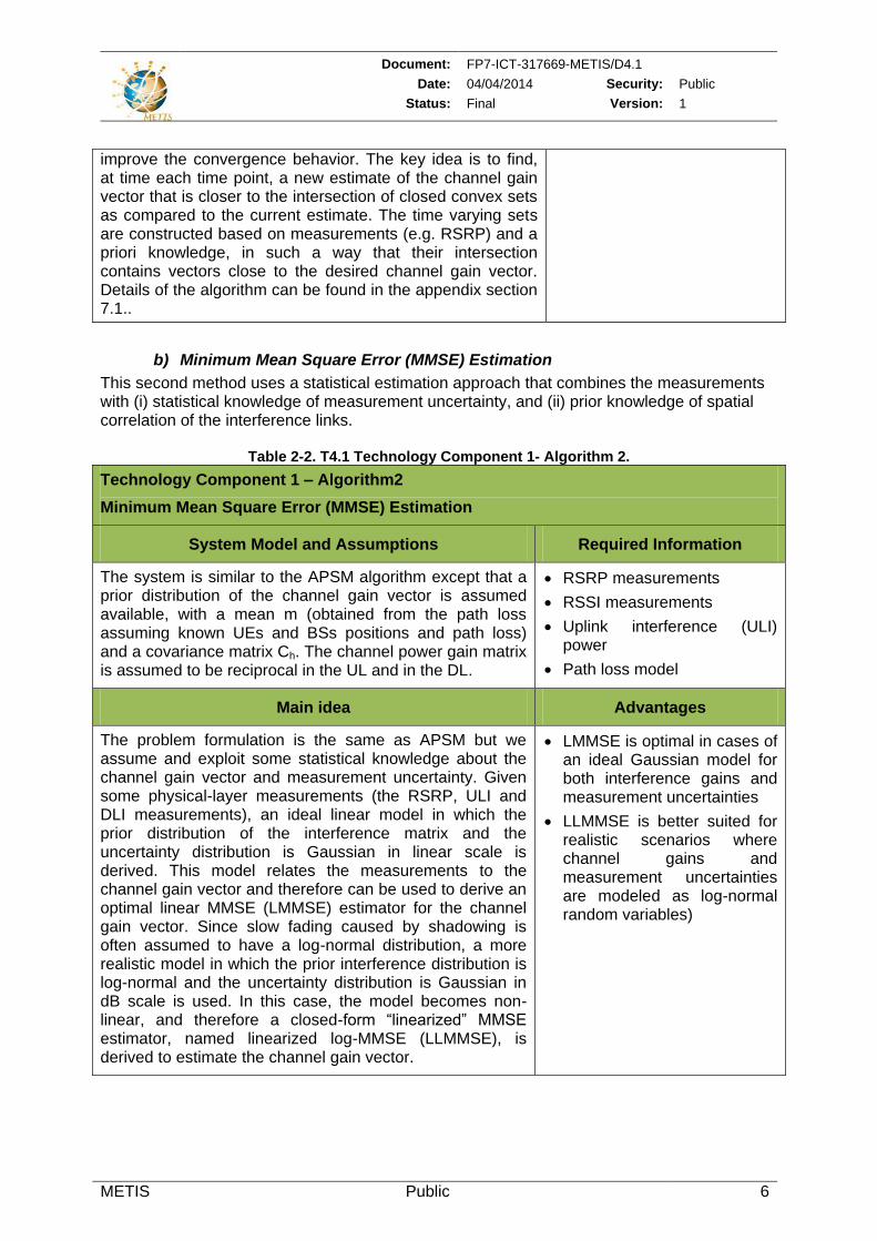
improve the convergence behavior. The key idea is to find, at time each time point, a new estimate of the channel gain vector that is closer to the intersection of closed convex sets as compared to the current estimate. The time varying sets are constructed based on measurements (e.g. RSRP) and a priori knowledge, in such a way that their intersection contains vectors close to the desired channel gain vector. Details of the algorithm can be found in the appendix section 7.1..
b) Minimum Mean Square Error (MMSE) Estimation
This second method uses a statistical estimation approach that combines the measurements with (i) statistical knowledge of measurement uncertainty, and (ii) prior knowledge of spatial correlation of the interference links.
Table 2-2. T4.1 Technology Component 1- Algorithm 2.
Technology Component 1 – Algorithm2
Minimum Mean Square Error (MMSE) Estimation
System Model and Assumptions Required Information
The system is similar to the APSM algorithm except that a prior distribution of the channel gain vector is assumed available, with a mean m (obtained from the path loss assuming known UEs and BSs positions and path loss) and a covariance matrix Ch. The channel power gain matrix is assumed to be reciprocal in the UL and in the DL.
RSRP measurements
RSSI measurements
Uplink interference (ULI) power
Path loss model
Main idea Advantages
The problem formulation is the same as APSM but we assume and exploit some statistical knowledge about the channel gain vector and measurement uncertainty. Given some physical-layer measurements (the RSRP, ULI and DLI measurements), an ideal linear model in which the prior distribution of the interference matrix and the uncertainty distribution is Gaussian in linear scale is derived. This model relates the measurements to the channel gain vector and therefore can be used to derive an optimal linear MMSE (LMMSE) estimator for the channel gain vector. Since slow fading caused by shadowing is often assumed to have a log-normal distribution, a more realistic model in which the prior interference distribution is log-normal and the uncertainty distribution is Gaussian in dB scale is used. In this case, the model becomes non-linear, and therefore a closed-form “linearized” MMSE estimator, named linearized log-MMSE (LLMMSE), is derived to estimate the channel gain vector.
LMMSE is optimal in cases of an ideal Gaussian model for both interference gains and measurement uncertainties
LLMMSE is better suited for realistic scenarios where channel gains and measurement uncertainties are modeled as log-normal random variables)
Document: FP7-ICT-317669-METIS/D4.1
Date: 04/04/2014 Security: Public
Status: Final Version: 1
METIS Public 7
2.2 Smart and coordinated resource usage
The purpose of this research topic is to design new resource allocation schemes to mitigate interference (within the same or between different layers in the network) and offer better resource reuse to maximize the network capacity. This includes assigning the resources (e.g., time, frequency or code) to communication entities, controlling their transmission powers and also selecting the appropriate transmission mode, e.g. cellular or direct D2D mode. This activity will use as inputs the results on interference identification derived within T4.1.
Although, the main focus is on a large time-scale (multiple TTIs or more), radio resource management techniques involving fixed resource usage patterns on a TTI time-scale where the adjustment of the usage patterns happens on a longer time scale could be also investigated. For example, a TTI level power control or scheduling algorithm may receive constraints or input parameters from a coarser time scale resource allocation algorithm.
At this stage, investigated smart and coordinated resource usage concepts are tailored mainly towards 3 METIS cross work packages topics: Device-to-device (D2D), Ultra Dense Network (UDN) and moving networks (MN). The following sections outline the main schemes considered which vary from partially/fully decentralized schemes, where decisions are taken by devices based on local information or context information exchanged with other devices or access nodes, to centralized schemes where the coordination is ensured by a central node (e.g. eNB). Based on a better understanding of the new challenges introduced by future communication systems, the necessary trade-offs in terms of performance vs. the degree of centralization can be investigated.
2.2.1 Smart and coordinated resource usage for D2D
Although the idea of enabling direct communications between devices was proposed by some early works on ad hoc networks, the concept of allowing local D2D communications to (re)use cellular spectrum resources simultaneously with ongoing cellular traffic, under the control of the network, is relatively new. This was mainly driven by three potential gains: proximity gain, reuse gain and hop gain.
1. The proximity between UEs allows for extreme high bit rates, low delays and low power consumption [KA08, DX08].
2. The reuse gain implies that radio resources may be simultaneously used by cellular as well as D2D links thereby tightening the reuse factor even of a reuse-1 system [DRW+09].
3. The hop gain refers to using a single link in the D2D mode rather than using an uplink and a downlink resource when communicating via the access point in the cellular mode.
Additionally, D2D communications may increase the reliability of cellular communications and facilitate new types of wireless peer-to-peer [MSL+11], [FKZ06], [CLL+10] and multicast services. However, enabling D2D communications reusing cellular spectrum poses new challenges for both discovery and communication phases. Firstly, power-efficient and scalable mechanisms are needed to allow discovering devices in the vicinity with low resources utilization. Moreover, when sharing the resources dedicated to the downlink or to the uplink cellular transmissions, the D2D links can disturb the reception at the BS or the UE, respectively. Therefore, one of the main challenges identified in our D2D studies in METIS is the mitigation of the interferences introduced by the D2D communications. A further challenge is to cope with the large SINR variations caused by both intra- and inter-cell interference.
In T4.1 we focus on better D2D resource usage mechanisms to achieve the aforementioned potential gains. In particular, new practical, low complexity algorithms needed for device discovery, mode selection, power control, scheduling, and resource allocation will be introduced.
Document: FP7-ICT-317669-METIS/D4.1
Date: 04/04/2014 Security: Public
Status: Final Version: 1
METIS Public 8
2.2.1.1 Device discovery
Neighbor discovery, sometimes referred to as device or peer discovery, is a fundamental component for enabling direct D2D communications. In particular, the emergence of location-based social network applications and proximity services increased the need for autonomous and power efficient continuous discovery mechanisms. This is typically based on the design of beacon or reference signals that are periodically broadcasted by devices to allow peer devices in their proximity to detect and identify them.
2.2.1.1.1 Literature review
In [VTG+09], neighbor discovery is modeled as the classical coupon collector’s problem. This model turns out to be powerful in terms of deriving analytical results and gaining insights of asymptotic behavior of neighbor discovery. The need for considering energy efficient beacon signaling was highlighted in a more refined radio model by [YSK+09], which explicitly takes into account the inherent trade-off between discovery time and beaconing duty cycle. Energy efficiency is also recognized as a key performance indicator by [DopWVit11] which introduces a novel device beaconing scheme to enable the exchange of small data packets and facilitates the connection setup.
A scalable neighbor discovery method for large wireless networks is developed by [NSW10]. In this work, the peer discovery process is advantageously modeled as a spatial coloring process (the colors corresponding to beacon resources such as frequency channels) and the channel assignment problem as a spatial coloring problem. Based on the insights, an online distributed algorithm for channel (beacon resource) assignment is developed and analyzed. Along another line, a series of works proposes device discovery schemes that rely on the joint (multiple) detection of several devices using the same resource. This line of contributions is represented by [VVM+11] and some references therein. It is shown that when multiple interfering users are jointly decoded on a single physical resource, the efficiency of the discovery process can be dramatically improved by proper MAC design.
Finally, a combined PHY and MAC layer design for device discovery is presented in [BKL+12], in which the inherent trade-offs between energy efficiency, discovery range and the required channel resources are taken into account. In this design, the PHY/MAC architecture is completely flat: there are no centralized entities that control the operation of other devices. In contrast, [FDP+12] describes peer and service discovery techniques that takes advantage of cellular network coverage and assistance of the cellular network. It is argued that such network assistance can improve the efficiency compared to a non-network assisted discovery processes.
2.2.1.1.2 Device discovery research
In METIS resource allocation aspects for D2D discovery are considered for network coverage and partial or out of network coverage scenarios. We assume dedicated resources available for the purpose of device discovery. These resources are further decomposed into time-frequency resources where UEs select the resources for transmitting discovery signals. The key question is how each UE should select/use a particular resource in a way that it avoids selecting resources used by other neighboring devices and hence increasing the probability of discovery (i.e. decreasing the collision risk between beacon signals). One possible approach, referred to as Network-(NW) based, is to control the discovery resource allocation by eNB. Another alternative, referred to as UE- based, could be a more decentralized approach where each UE autonomously selects a certain resource according to a common set of rules. The Table 2-3 below shows a comparison between the two discovery solutions.
Document: FP7-ICT-317669-METIS/D4.1
Date: 04/04/2014 Security: Public
Status: Final Version: 1
METIS Public 9
Table 2-3. Comparison of D2D Discovery Solutions.
Principle Advantages Drawbacks
UE- based discovery
Each UE picks one discovery resource (DR) from all available resources based on local observations.
Scalable, self-organized
Spatial re-use possible
Support both under and out of NW coverage
Collisions risks
Critical for delay- sensitive applications
Local sub-optimal
NW- based discovery
eNB assigns resources to each UE maintaining intra-cell orthogonality.
No collisions
Short discovery delays
Low resource utilization
High RRC signalling overhead
Not applicable for out of NW coverage
2.2.1.1.3 Technology Component 2: Unified Solution for Device Discovery
One of the technology components proposed at this stage of the project is a unified device discovery solution applicable for both network coverage and partial or/out of network coverage scenarios. The main foundations and assumptions of the unified solution are described in the table below.
Table 2-4. T4.1 Technology Component 2.
T4.2 Technology Component 2
Unified Solution for Device Discovery
System Model and Assumptions Required Information
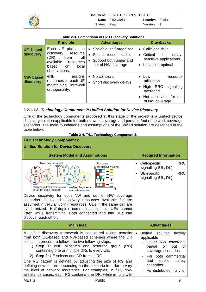
Device discovery for both NW and out of NW coverage scenarios. Dedicated discovery resources available for are assumed in cellular uplink resources. UEs in the same cell are synchronized. Half-duplex communication, i.e., UEs cannot listen while transmitting. Both connected and idle UEs can discover each other.
Cell-specific RRC signalling (UL, DL)
UE-specific RRC signalling (UL, DL)
Main idea Advantages
A unified discovery framework is considered taking benefits from both UE-based and NW-based schemes where the DR allocation procedure follows the two following steps:
1) Step 1: eNB allocates one resource group (RG) containing one or multiple DRs to every UE.
2) Step 2: UE selects one DR from its RG
One RG pattern is defined by adjusting the size of RG and defining new pattern depending on the scenario in order to vary the level of network assistance. For examples, in fully NW-assistance cases, each RG contains one DR, while in fully UE-
Unified solution flexibly applicable - Under NW coverage,
partial or out of coverage scenarios.
- For both commercial and public safety scenarios.
- As distributed, fully or
Document: FP7-ICT-317669-METIS/D4.1
Date: 04/04/2014 Security: Public
Status: Final Version: 1
METIS Public 10
based the RG corresponds to all the DRs available for the discovery. For partial UE-based scheme the available DRs are divided into different RG and each UE is assigned one RG from which it picks autonomously one DR to broadcast its discovery signal. The system operates using one RG pattern at a time and all UEs are assumed to follow the same pattern. Methods for adjusting the RG and grouping UEs (using each RG) to achieve high resource reuse are investigated to increase the discovery efficiency.
partially centralized.
No extra-costs or complexity needed for adding several new modules for both UEs and network nodes.
2.2.1.2 D2D communications
For the D2D communication phase the research works consider D2D communications as an underlay to the cellular network and where the two potential transmission modes are:
Cellular Mode, where the UEs communicate with each other via the BS,
D2D Mode, where one UE will communicate directly with another UE.
The objective is to mitigate interference that D2D communications may cause to the cellular users (CUEs) both considering and excluding the coexistence of D2D and cellular communications sharing the same resources. This optimization can be achieved via four means: mode selection (MS), SINR target setting, power control and resource allocations.
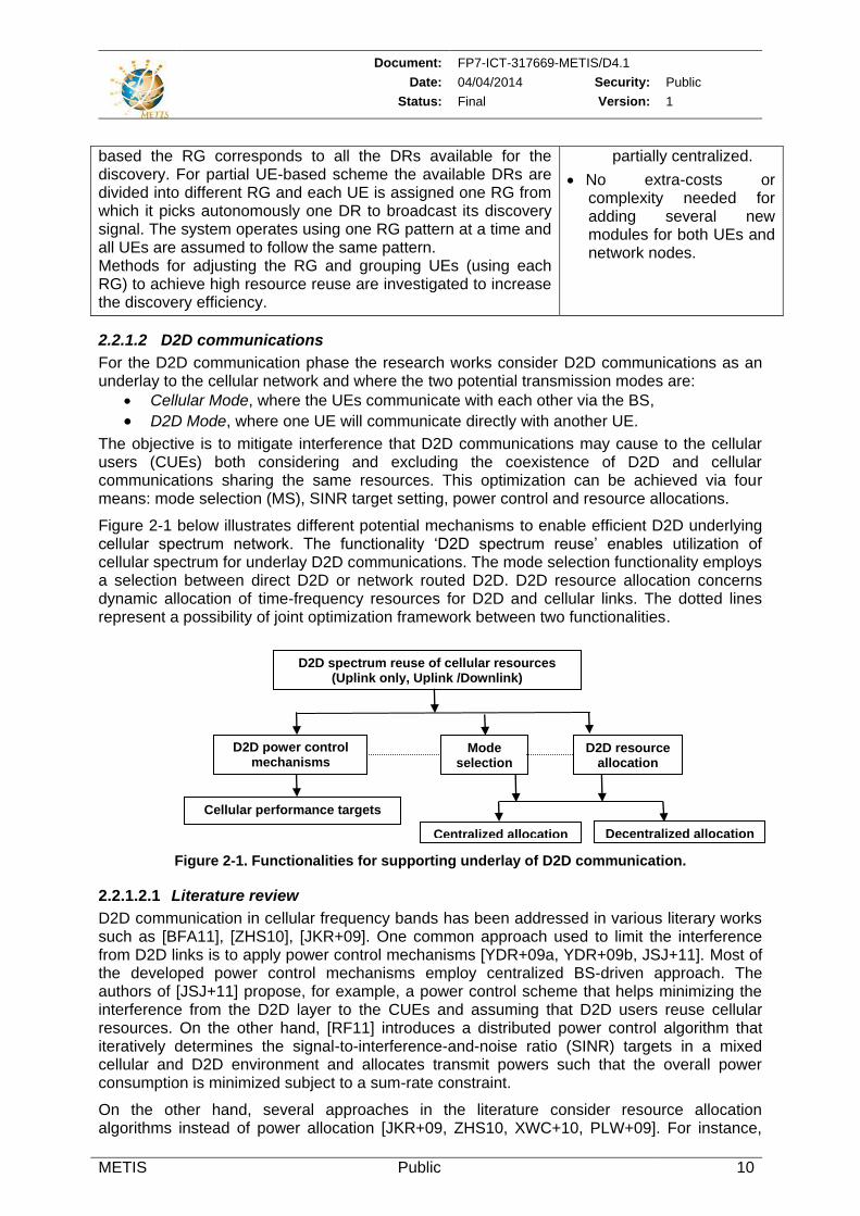
Figure 2-1 below illustrates different potential mechanisms to enable efficient D2D underlying cellular spectrum network. The functionality ‘D2D spectrum reuse’ enables utilization of cellular spectrum for underlay D2D communications. The mode selection functionality employs a selection between direct D2D or network routed D2D. D2D resource allocation concerns dynamic allocation of time-frequency resources for D2D and cellular links. The dotted lines represent a possibility of joint optimization framework between two functionalities.
Figure 2-1. Functionalities for supporting underlay of D2D communication.
2.2.1.2.1 Literature review
D2D communication in cellular frequency bands has been addressed in various literary works such as [BFA11], [ZHS10], [JKR+09]. One common approach used to limit the interference from D2D links is to apply power control mechanisms [YDR+09a, YDR+09b, JSJ+11]. Most of the developed power control mechanisms employ centralized BS-driven approach. The authors of [JSJ+11] propose, for example, a power control scheme that helps minimizing the interference from the D2D layer to the CUEs and assuming that D2D users reuse cellular resources. On the other hand, [RF11] introduces a distributed power control algorithm that iteratively determines the signal-to-interference-and-noise ratio (SINR) targets in a mixed cellular and D2D environment and allocates transmit powers such that the overall power consumption is minimized subject to a sum-rate constraint.
On the other hand, several approaches in the literature consider resource allocation algorithms instead of power allocation [JKR+09, ZHS10, XWC+10, PLW+09]. For instance,
D2D spectrum reuse of cellular resources (Uplink only, Uplink /Downlink)
D2D power control mechanisms
D2D resource allocation
Cellular performance targets
Centralized allocation Decentralized allocation
Mode selection
Document: FP7-ICT-317669-METIS/D4.1
Date: 04/04/2014 Security: Public
Status: Final Version: 1
METIS Public 11
the approach proposed in [JaVTC09] exploits the knowledge of slow-scale parameters, such as path loss or shadowing to perform interference-aware resource allocation. Similarly, in [ZHS10] a greedy heuristic algorithm utilizing cross-channel gain information between D2D and cellular pairs to reduce the interference to cellular receivers is proposed. Both the cellular uplink and downlink frames are utilized, while D2D power control is assumed in uplink frames. The aforementioned work considers resource allocation on a per cell basis, without considering the effect of inter-cell interference. In [PLW+09] two mechanisms are proposed: one is mitigating the interference from cellular transmission to D2D communication by an interference tracing approach, while the other one is aiming to reduce the interference from D2D transmission to cellular communication by a tolerable interference broadcasting approach.
Other existing solutions include interference avoidance mechanisms based on a proper transmission mode selection. Such an approach is considered for example in [DoWCNC10], where the base station is assumed to have all the involved channel state information (CSI) to select the optimal resource sharing mode (i.e. D2D mode reusing cellular resources, D2D mode using orthogonal resources and cellular mode in which the D2D pair communicates through the cellular BS). Some papers consider joint power optimization, resource allocation and mode selection methods. In [XTL11] Xiao et al. proposed a method with the aim to minimize the total downlink transmission power, constrained by users’ QoS demands. Similarly, in [BFA11] joint mode selection, resource allocation, power assignment, joint resource allocation and power control algorithm is considered in [YDR+11].
Since the main motivation and justification of allowing D2D communications in cellular spectrum is ultimately to harvest some capacity, sum-rate or sum-power gain, many papers apply optimization techniques to explore the potential of cellular D2D communications [YDR+11, YDR+09c, YDR+09b]. These works provide important reference cases when the assumption can be made that the BS is aware of CSI not only between transmitter-receiver pairs, but also of the interference links, such as, for example the state of the link between the D2D transmitter and the cellular receiver and/or the cellular transmitter and the D2D receiver.
Typically, existing works give priority to the cellular users, avoids or constraints the interference caused by the D2D users to the cellular layer, see for example [MLP+11, PLW+09]. However, it can be argued that D2D traffic should be treated near equally to the cellular traffic as long as fairness between all cellular spectrum users (i.e. cellular and D2D users) are handled [BFA11] [FDP+12], since they all use cellular spectrum under operator controlled charging conditions.
2.2.1.2.2 Technology Component 3: Novel mode selection schemes for D2D
It is intuitively clear that for a given D2D candidate the benefit of direct communication mode depends on the geometry of the D2D pair and the UEs using the same RBs in the own cell and neighbor cells. The mode selection is a D2D specific function that allows the BS to dynamically adjust the characteristics of the D2D link and to change the communication mode between the pair of devices. It plays a similar role for D2D communications as handover does for traditional cellular communications. Accordingly the appropriate time scale for MS is in the order of several hundreds of millisecond.
The following sub-sections introduce two new mode selection (MS) algorithms that can be applicable in multi-cell cellular systems supporting D2D communications. The first algorithm relies on SNR rather than SINR metrics to avoid dependency on the transmit powers of the interferers (D2D receiver or BS). In the second algorithm the user geographical location information is used by the BS to decide the appropriate transmission mode (direct link or via base station) to be used between two UEs.
Document: FP7-ICT-317669-METIS/D4.1
Date: 04/04/2014 Security: Public
Status: Final Version: 1
METIS Public 12
Table 2-5. T4.1 Technology Component 3 – Approach 1.
Technology Component 3 – Approach 1
Distributed CSI-based mode selection for D2D
System Model and Assumptions Required Information
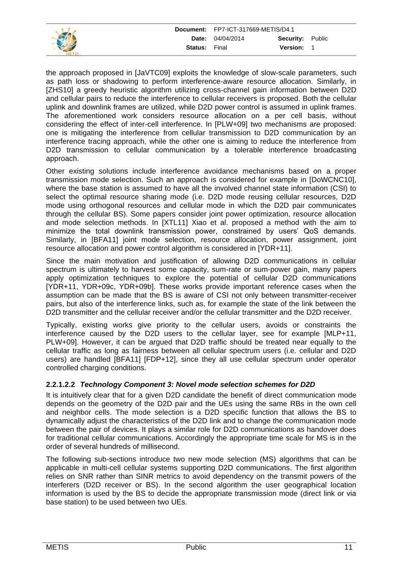
Cellular and a D2D links are multiplexed on the same uplink OFDM Physical Resource Block (PRB). At most one Cellular UE can be allocated on a PRB (without D2D, intra-cell orthogonality is maintained). At most one D2D link is allocated to one PRB used by a cellular UE (i.e. for any one PRB, there are at most two links, one cellular and one D2D).
Single cell information about large scale CQI (distance dependent path loss and shadowing) of the D2D Transmistter-D2D Receiver and D2D Transmitter-eNB links.
Main idea Advantages
The algorithm only depends on the information that is specific to the D2D pair. It requires large scale fading between the D2D transmitter and receiver (g2 in figure above) and between the D2D Transmitter and the base station (g3). It first calculates hypothetical SNR values for each link (see details in Annex 7.2). Then the D2D mode is selected if the hypothetical capacity values corresponding to the useful links are higher than the hypothetical capacity values of the interfering links plus a Δ value, which is a tuneable system parameter measured in bit/s/Hz. The transmit power value p is set to an arbitrary positive value. By increasing Δ, the MS algorithm becomes more conservative and selects D2D mode more cautiously. Selecting a negative Δ implies a more frequent D2D mode selection. After selecting the mode, the inter-cell interference can be addressed by resource allocation (scheduling) and power control to avoid unacceptable complexity in real systems when mode selection decisions need to be coordinated among multiple cells.
Mitigates the complexity of joint power control and mode selection: by relying only on SNR metric, it can be executed independently of the transmit power setting and prior to pairing (i.e. deciding on the UE that uses the same PRB as the D2D pair).
Document: FP7-ICT-317669-METIS/D4.1
Date: 04/04/2014 Security: Public
Status: Final Version: 1
METIS Public 13
Table 2-6. T4.1 Technology Component 3 – Approach 2.
Technology Component 3 – Approach 2
Location-based mode selection for D2D
System Model and Assumptions Required Information
CUEs and D2D pairs sharing either uplink or downlink PRB. Intra-cell orthogonality is maintained between CUEs i.e. CUEs used different PRBs. Many D2D links can be scheduled at the same cellular RB. FDD operation is assumed.
User’s geographical location (D2D and cellular users).
Path loss model
Main idea Advantages
Based on users’ location information the BS estimates the distances between candidate users for D2D pair and between each of the candidate users and the base station. The distances are then mapped to corresponding received signal powers by utilizing appropriate path loss model. Based on the distance and the path loss estimation, the base station decides whether the users can transmit using a direct link or via the base station. Thus, the direct link can be chosen if the distance between the users is smaller than the distance between any of users and the BS and smaller than a predefined
arbitrary limit . The cellular mode is chosen otherwise. When the distance requirements are met the BS searches for resources for to be shared with the D2D link and specifies the lower and upper bounds on D2D pair transmission powers using path loss estimation. The impact of the fading on can be investigated at later stage.
Seamlessness transition between cellular and D2D mode
No channel state information is required from the D2D candidates
2.2.1.2.3 Technology Component 4: New methods for D2D Resource Allocation
Resource allocation consist in the assignment of dedicated resources not being used by CUEs to the D2D link or selecting the best cellular candidate to share resources with the D2D pair while maintaining a tolerable interference level. Below four different alternatives are proposed for achieving efficient resources allocation in mixed cellular and D2D environments. The first method extends the current ICIC schemes to enable using the muted resources (e.g. subframes) of macro cells by D2D links. The second approach considers a joint coordinated resource allocation of D2D and cellular links including both inter-cell interference and mode selection similar to [BFA11]. However in contrast to [BFA11], the focus is on solutions suitable for indoor dense deployments dominated by inter-cell interferences and tailored for network-level KPIs such as time delay. The third method exploits the SIR estimation in order find the best radio resource sharing pattern for D2D users that minimize the interference with the cellular transmissions.
In contrast to three first schemes which focus mainly on static or semi-static (low-mobility) users, the forth method focuses on resources allocation for high-mobility users (devices embedded into vehicles or vehicular user equipment).
Document: FP7-ICT-317669-METIS/D4.1
Date: 04/04/2014 Security: Public
Status: Final Version: 1
METIS Public 14
Table 2-7. T4.1 Technology Component 4 – Approach 1.
Technology Component 4 – Approach 1
Further enhanced ICIC for enabling D2D in heterogeneous networks
System Model and Assumptions Required Information
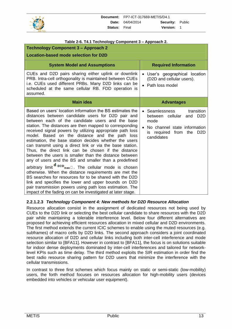
Heterogeneous network where D2D links are using the cellular downlink resources. Macro layer resources partially muted in the time domain (TDM eICIC) or alternatively in the frequency domain.
UE measurements e.g., RSSI from pico-cells
UE data rate requirements
Main idea Advantages
The main idea is to use interference measurements to schedule D2D links in muted macro cell sub-frames according to the following rules:
If no strong small cell (SC) transmission is detected in some muted resources of the macro cell these resources can be used by D2D pairs or clusters that are under the same macro layer, otherwise unmuted resources are used.
If the D2D pair is under different layers (macro and SC layers), the muted resources can only be used if the D2D resource allocation is controlled by the SC or an indication is available at the SC.
Increase network capacity without introducing intolerable interference to the small cells
Document: FP7-ICT-317669-METIS/D4.1
Date: 04/04/2014 Security: Public
Status: Final Version: 1
METIS Public 15
Table 2-8. T4.1 Technology Component 4 – Approach 2.
Technology Component 4 – Approach 2
Multi-cell coordinated and flexible resource allocation for D2D
System Model and Assumptions Required Information
Mixed cellular and D2D communications where the resource allocation is performed by the eNB or a coordinator node. MIMO IRC/MMSE receiver is used at D2D receiver and eNB side. The D2D pair communicates over a bidirectional channel operating in TDD mode.
Fast fading channel knowledge at the coordinator or at the SC or eNB.
Channel information at D2D receivers
Main idea Advantages
The contribution considers D2D and cellular resource management in a holistic way. Combined resource allocation, and mode selection of D2D (Figure 2-1) are especially studied. Potential benefit of interference cancellation will also be investigated as part of resource allocation. We note that D2D mode selection and interference cancellation can be used to extend the range of direct D2D. D2D power control will also be potentially considered for improving system level KPI.
Improved spectrum utilisation and better inter-cell interference coordination for D2D resource allocation.
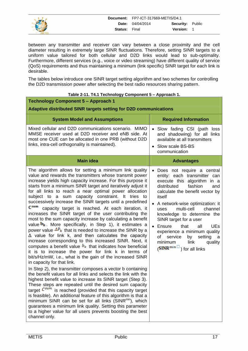
Table 2-9. T4.1 Technology Component 4 – Approach 3.
Technology Component 4 – Approach 3
Location-based D2D resource allocation
System Model and Assumptions Required Information
Cellular users and D2D pairs sharing either uplink or downlink PRBs. Intra-cell orthogonality is maintained between CUEs. Many D2D links can be scheduled in the same cellular RB. FDD operation is assumed.
Users geographical location (D2D users and cellular users)
Path loss model
Main idea Advantages
The BS uses the distances between the users and between the users and the BS to estimate the path losses and the SIR for users sharing the same resources, accordingly. The selection of the best candidate for resource sharing is performed based on the distance maximization. In fact, since the path loss has the biggest impact on interference, increasing the distance from interferers maximizes SIRs. The distance requirements for resource sharing are:
DL resource sharing: the distance between the CUE
Simplicity
No channel state information is required from the D2D users (even though such information can enhance the scheme)
Efficient intra-cell interference mitigation. A central entity has control of D2D links and
Document: FP7-ICT-317669-METIS/D4.1
Date: 04/04/2014 Security: Public
Status: Final Version: 1
METIS Public 16
and BS ( ) should be above the distance between the
D2D receiver and the BS ( ) and the distance
between the D2D pair ( ) should be smaller than the
distance between the CUE and the D2D sender ( ). Among the CUEs that meet these requirements, the user selected for resource sharing is the one
maximizing the distance towards the D2D sender ( ).
UL resource sharing: the distance between the CUE
and BS ( ) should be below the distance between the
D2D receiver and the CUE ( ) as well as the distance
between the BS and the D2D sender ( ). The priority is given to CUE maximizing the distance towards the
D2D receiver ( ).
This scheme allows different D2D pairs to share the same cellular resources. In this case the separation between receivers and transmitters of different D2D pairs has to be greater than the length of the D2D link.
so the interference caused by D2D communications
Increases the capacity of the network by allowing scheduling multiple D2D pairs on same frequency resources
Table 2-10. T4.1 Technology Component 4 – Approach 4.
Technology Component 4 – Approach 4
Context-aware resource allocation scheme for enabling D2D in moving networks
System Model and Assumptions Required Information
Network-assisted D2D in underlay mode where the focus lies on signalling for RRM including power control and mode selection.
Location and trajectory of users/vehicles
Knowledge about the resources available for the whole system
Main idea Advantages
The purpose of this work is to evaluate the required RRM enablers from link level perspective and develop mechanisms to derive and exchange link level context information in order to allow efficient RRM for D2D.
This context data consists of different device characteristics and link-level information such as mobility, service requirements, air interface capabilities, user location and channel quality.
Reduced latency
Reliability
Low signalling overhead
2.2.1.2.4 Technology Component 5: Methods for Power Control and SINR target Setting for D2D
While the mode selection and the resource allocation are usually set for a coarse time scale (e.g. hundreds of milliseconds), a shorter time scale is needed for managing the D2D link more autonomously by the devices forming the D2D pair or group. For example, at each mode selection instant, the eNB can allocate a set of PRBs and a maximum power level to be used by the D2D link, while the D2D pair can exercise adaptive modulation and coding scheme selection, scheduling within the assigned resource pool or power control to combat (fast) fading on the short time scale. Power control mechanisms can be optionally combined with an SINR target setting algorithm that allows minimizing the overall used power subject to a sum rate target. In fact, due to the presence of D2D transmitters and receivers, the distances
Document: FP7-ICT-317669-METIS/D4.1
Date: 04/04/2014 Security: Public
Status: Final Version: 1
METIS Public 17
between any transmitter and receiver can vary between a close proximity and the cell diameter resulting in extremely large SINR fluctuations. Therefore, setting SINR targets to a uniform value tailored for both cellular and D2D links would lead to sub-optimality. Furthermore, different services (e.g., voice or video streaming) have different quality of service (QoS) requirements and thus maintaining a minimum (link specific) SINR target for each link is desirable.
The tables below introduce one SINR target setting algorithm and two schemes for controlling the D2D transmission power after selecting the best radio resources sharing pattern.
Table 2-11. T4.1 Technology Component 5 – Approach 1.
Technology Component 5 – Approach 1
Adaptive distributed SINR targets setting for D2D communications
System Model and Assumptions Required Information
Mixed cellular and D2D communications scenario. MIMO MMSE receiver used at D2D receiver and eNB side. At most one CUE can be allocated in one PRB (without D2D links, intra-cell orthogonality is maintained).
Slow fading CSI (path loss and shadowing) for all links available at all transmitters
Slow scale BS-BS communication
Main idea Advantages
The algorithm allows for setting a minimum link quality value and rewards the transmitters whose transmit power increase yields high capacity increase. For this purpose it starts from a minimum SINR target and iteratively adjust it for all links to reach a near optimal power allocation subject to a sum capacity constraint. It tries to successively increase the SINR targets until a predefined
capacity target is reached. At each iteration, it increases the SINR target of the user contributing the most to the sum capacity increase by calculating a benefit
value . More specifically, in Step 1), it estimates a
power value that is needed to increase the SINR by a Δ value for link k, and then calculates the capacity increase corresponding to this increased SINR. Next, it
computes a benefit value that indicates how beneficial it is to increase the power for link k in terms of bit/s/Hz/mW, i.e., what is the gain of the increased SINR in capacity for that link.
In Step 2), the transmitter composes a vector b containing the benefit values for all links and selects the link with the highest benefit value to increase its SINR target (Step 3). These steps are repeated until the desired sum capacity
target is reached (provided that this capacity target is feasible). An additional feature of this algorithm is that a minimum SINR can be set for all links (SINRmin), which guarantees a minimum link quality. Setting this parameter to a higher value for all users prevents boosting the best channel only.
Does not require a central entity: each transmitter can execute this algorithm in a distributed fashion and calculate the benefit vector by itself
A network-wise optimization: it uses multi-cell channel knowledge to determine the SINR target for a user
Ensure that all UEs experience a minimum quality of service by setting a minimum link quality
( ) for all links
Document: FP7-ICT-317669-METIS/D4.1
Date: 04/04/2014 Security: Public
Status: Final Version: 1
METIS Public 18
Table 2-12. T4.1 Technology Component 5 – Approach 2.
Technology Component 5 – Approach 2
Distributed iterative D2D power control algorithm
System Model and Assumptions Required Information
Mixed cellular and D2D communications. MIMO MMSE receiver used both at the D2D receiver and eNB side. A D2D pair communicates over a bidirectional channel and the D2D link operating in a TDD mode.
Each transmitter-k estimates its channel to its receiver
( )
RSSI type of measurements
Main idea Advantages
The algorithm exploits covariance measurement performed by D2D receivers ((fast) RSSI type of measurements) and fed back in a distributed fashion to their respective transmitters to adjust their transmit powers in a way that predefined SINR targets are reached (The steps are summarized by the pseudo-code of Algorithm 3 in appendix 7.2).
Each Receiver-k estimates the covariance matrix of the
total received interference-plus-noise ( and feeds it back to the transmitter. The transmitter calculates the
reduced covariance matrix ( ) as well as the effective interference and estimate the diagonal power loading
matrix ( ) and the transmit power ( ). The algorithm
iteratively adjusts the power matrix such that the MIMO streams that suffer from higher effective interference are allocated higher transmit power. In fact, with equal power loading, when the “weakest” stream’s SINR is raised to the target, the stronger streams tend to overshoot the SINR target and thereby to waste transmit
power. The transmit power ) is itself determined by the MIMO stream that requires the highest transmit power (proportional to the effective interference and target SINR).
In a practical implementation, the algorithm could be executed on a slower time scale relaxing the requirement on the receiver feedback.
Distributed algorithm executed on a faster time scale to compensate for the large dynamics of the SINR variations of the D2D and cellular links
No extensive reference signal processing and channel quality information reporting are required
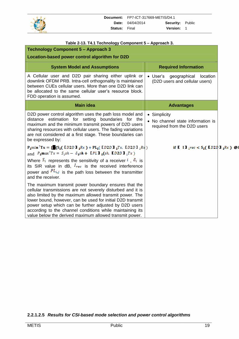
Document: FP7-ICT-317669-METIS/D4.1
Date: 04/04/2014 Security: Public
Status: Final Version: 1
METIS Public 19
Table 2-13. T4.1 Technology Component 5 – Approach 3.
Technology Component 5 – Approach 3
Location-based power control algorithm for D2D
System Model and Assumptions Required Information
A Cellular user and D2D pair sharing either uplink or downlink OFDM PRB. Intra-cell orthogonality is maintained between CUEs cellular users. More than one D2D link can be allocated to the same cellular user’s resource block. FDD operation is assumed.
User’s geographical location (D2D users and cellular users)
Main idea Advantages
D2D power control algorithm uses the path loss model and distance estimation for setting boundaries for the maximum and the minimum transmit powers of D2D users sharing resources with cellular users. The fading variations are not considered at a first stage. These boundaries can be expressed by:
and
Where represents the sensitivity of a receiver , is
its SIR value in dB, is the received interference
power and is the path loss between the transmitter and the receiver.
The maximum transmit power boundary ensures that the cellular transmissions are not severely disturbed and it is also limited by the maximum allowed transmit power. The lower bound, however, can be used for initial D2D transmit power setup which can be further adjusted by D2D users according to the channel conditions while maintaining its value below the derived maximum allowed transmit power.
Simplicity
No channel state information is required from the D2D users
2.2.1.2.5 Results for CSI-based mode selection and power control algorithms
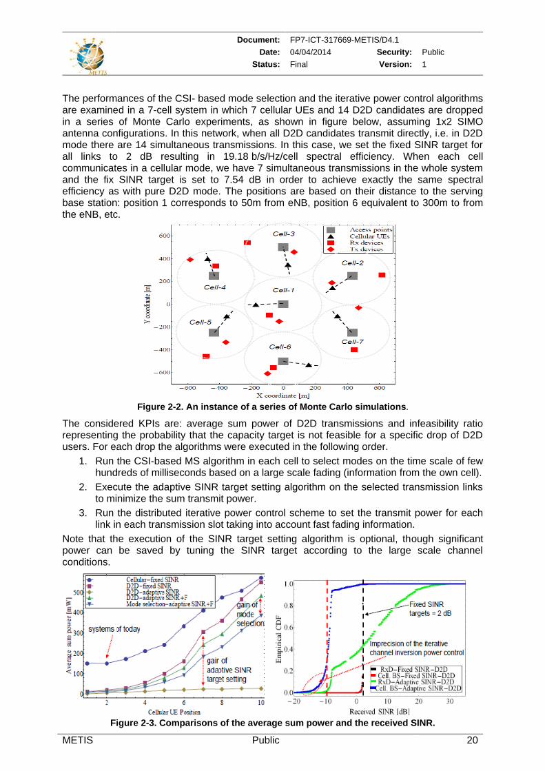
Document: FP7-ICT-317669-METIS/D4.1
Date: 04/04/2014 Security: Public
Status: Final Version: 1
METIS Public 20
The performances of the CSI- based mode selection and the iterative power control algorithms are examined in a 7-cell system in which 7 cellular UEs and 14 D2D candidates are dropped in a series of Monte Carlo experiments, as shown in figure below, assuming 1x2 SIMO antenna configurations. In this network, when all D2D candidates transmit directly, i.e. in D2D mode there are 14 simultaneous transmissions. In this case, we set the fixed SINR target for all links to 2 dB resulting in 19.18 b/s/Hz/cell spectral efficiency. When each cell communicates in a cellular mode, we have 7 simultaneous transmissions in the whole system and the fix SINR target is set to 7.54 dB in order to achieve exactly the same spectral efficiency as with pure D2D mode. The positions are based on their distance to the serving base station: position 1 corresponds to 50m from eNB, position 6 equivalent to 300m to from the eNB, etc.
Figure 2-2. An instance of a series of Monte Carlo simulations.
The considered KPIs are: average sum power of D2D transmissions and infeasibility ratio representing the probability that the capacity target is not feasible for a specific drop of D2D users. For each drop the algorithms were executed in the following order.
1. Run the CSI-based MS algorithm in each cell to select modes on the time scale of few hundreds of milliseconds based on a large scale fading (information from the own cell).
2. Execute the adaptive SINR target setting algorithm on the selected transmission links to minimize the sum transmit power.
3. Run the distributed iterative power control scheme to set the transmit power for each link in each transmission slot taking into account fast fading information.
Note that the execution of the SINR target setting algorithm is optional, though significant power can be saved by tuning the SINR target according to the large scale channel conditions.
Figure 2-3. Comparisons of the average sum power and the received SINR.
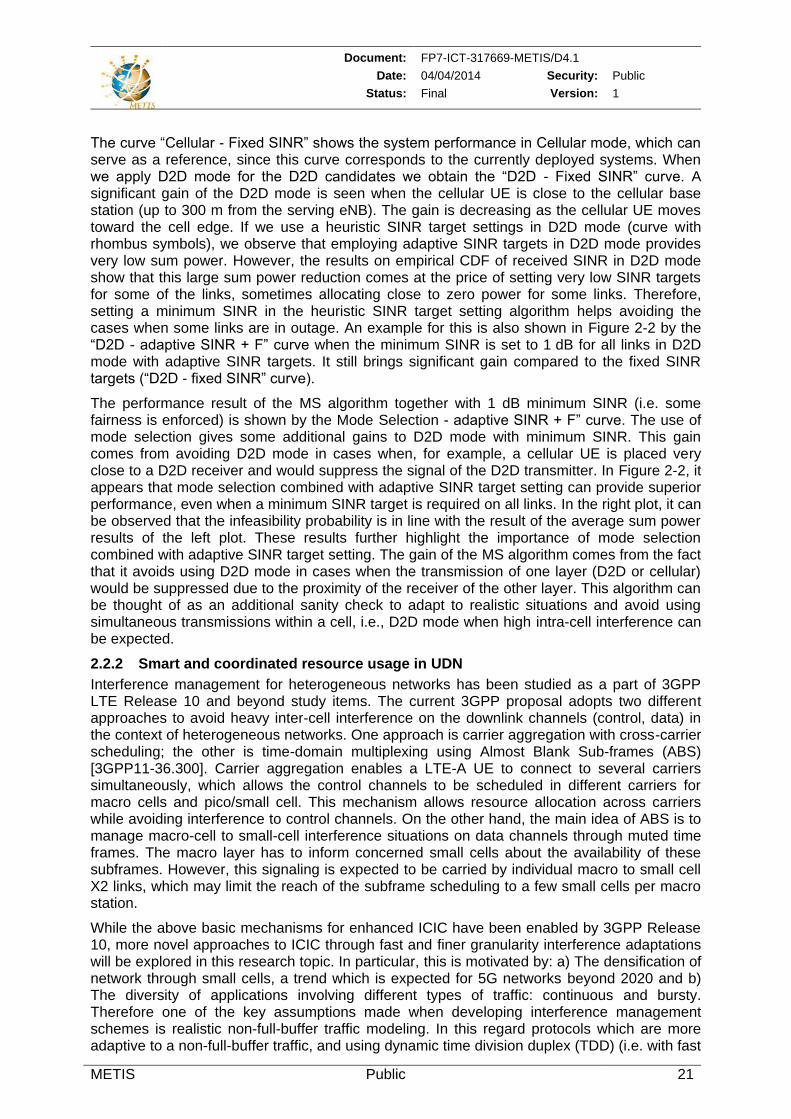
Document: FP7-ICT-317669-METIS/D4.1
Date: 04/04/2014 Security: Public
Status: Final Version: 1
METIS Public 21
The curve “Cellular - Fixed SINR” shows the system performance in Cellular mode, which can serve as a reference, since this curve corresponds to the currently deployed systems. When we apply D2D mode for the D2D candidates we obtain the “D2D - Fixed SINR” curve. A significant gain of the D2D mode is seen when the cellular UE is close to the cellular base station (up to 300 m from the serving eNB). The gain is decreasing as the cellular UE moves toward the cell edge. If we use a heuristic SINR target settings in D2D mode (curve with rhombus symbols), we observe that employing adaptive SINR targets in D2D mode provides very low sum power. However, the results on empirical CDF of received SINR in D2D mode show that this large sum power reduction comes at the price of setting very low SINR targets for some of the links, sometimes allocating close to zero power for some links. Therefore, setting a minimum SINR in the heuristic SINR target setting algorithm helps avoiding the cases when some links are in outage. An example for this is also shown in Figure 2-2 by the “D2D - adaptive SINR + F” curve when the minimum SINR is set to 1 dB for all links in D2D mode with adaptive SINR targets. It still brings significant gain compared to the fixed SINR targets (“D2D - fixed SINR” curve).
The performance result of the MS algorithm together with 1 dB minimum SINR (i.e. some fairness is enforced) is shown by the Mode Selection - adaptive SINR + F” curve. The use of mode selection gives some additional gains to D2D mode with minimum SINR. This gain comes from avoiding D2D mode in cases when, for example, a cellular UE is placed very close to a D2D receiver and would suppress the signal of the D2D transmitter. In Figure 2-2, it appears that mode selection combined with adaptive SINR target setting can provide superior performance, even when a minimum SINR target is required on all links. In the right plot, it can be observed that the infeasibility probability is in line with the result of the average sum power results of the left plot. These results further highlight the importance of mode selection combined with adaptive SINR target setting. The gain of the MS algorithm comes from the fact that it avoids using D2D mode in cases when the transmission of one layer (D2D or cellular) would be suppressed due to the proximity of the receiver of the other layer. This algorithm can be thought of as an additional sanity check to adapt to realistic situations and avoid using simultaneous transmissions within a cell, i.e., D2D mode when high intra-cell interference can be expected.
2.2.2 Smart and coordinated resource usage in UDN
Interference management for heterogeneous networks has been studied as a part of 3GPP LTE Release 10 and beyond study items. The current 3GPP proposal adopts two different approaches to avoid heavy inter-cell interference on the downlink channels (control, data) in the context of heterogeneous networks. One approach is carrier aggregation with cross-carrier scheduling; the other is time-domain multiplexing using Almost Blank Sub-frames (ABS) [3GPP11-36.300]. Carrier aggregation enables a LTE-A UE to connect to several carriers simultaneously, which allows the control channels to be scheduled in different carriers for macro cells and pico/small cell. This mechanism allows resource allocation across carriers while avoiding interference to control channels. On the other hand, the main idea of ABS is to manage macro-cell to small-cell interference situations on data channels through muted time frames. The macro layer has to inform concerned small cells about the availability of these subframes. However, this signaling is expected to be carried by individual macro to small cell X2 links, which may limit the reach of the subframe scheduling to a few small cells per macro station.
While the above basic mechanisms for enhanced ICIC have been enabled by 3GPP Release 10, more novel approaches to ICIC through fast and finer granularity interference adaptations will be explored in this research topic. In particular, this is motivated by: a) The densification of network through small cells, a trend which is expected for 5G networks beyond 2020 and b) The diversity of applications involving different types of traffic: continuous and bursty. Therefore one of the key assumptions made when developing interference management schemes is realistic non-full-buffer traffic modeling. In this regard protocols which are more adaptive to a non-full-buffer traffic, and using dynamic time division duplex (TDD) (i.e. with fast
Document: FP7-ICT-317669-METIS/D4.1
Date: 04/04/2014 Security: Public
Status: Final Version: 1
METIS Public 22
flexible uplink, downlink split based on instantaneous load) have to be designed for future systems.
As part of T4.1 study on UDNs, we investigate algorithms and protocols which encompass the following: a) muting in time and frequency domains, b) user scheduling and radio resource management (resource allocation, power control), and c) interference avoidance approaches through radio resource management.
2.2.2.1 State-of-the-art
The interference management schemes are broadly classified into: centralized and decentralized. The centralized approaches make use of a coordination entity (coordinator) for smart radio resource management and can be further classified into fully centralized or hybrid (partially centralized). Decentralized schemes, on the other hand, are characterized by the absence of such coordinator and the resource allocation decisions are made individually by the SC themselves. They can be further split into implicit and explicit coordination schemes. Under implicit coordination no signaling is required between neighboring SCs in a given area. Examples of implicit coordination schemes are proposed in [EHB08], [CCK+10] which investigate performances of local area networks (small cells). On the contrary, explicit coordination assumes that SCs exchange signaling information to coordinate their radio resource usage and mitigate interferences. The coalition based scheme in [GCC+10] is an example of explicit coordination. Although in decentralized schemes there could be signaling between neighboring SCs, the smart resource decision making is still left to the individual access nodes. In general, the aforementioned interference coordination schemes do not consider a) flexible uplink and downlink resource split in dynamic TDD, and b) the use of context information such as packet deadlines and traffic patterns. In fact, dynamic TDD seems to be an interesting option to adapt resources allocation to the changing traffic demand of uplink and downlink and adjust it to the strong UL/DL traffic asymmetry, observed in today’s networks and expected to grow in future wireless systems, hence improving the efficiency of resource utilization. LTE-Advanced provides configuration support for dynamic TDD through seven different patterns of switching [3GPP13-36211], which effectively capture various TDD time switching ratios. Nevertheless, uncoordinated dynamic TDD switching may lead to significantly worse interference conditions experienced both by user equipment and network access nodes. Thus, using flexible TDD allocation per cell is avoided [KCS+12] and usually the same configuration over the entire system is adopting. The aspects of dynamic TDD have been addressed in several publications [JRK12] [WVS+12]. In [WVS+12] the user throughput based system level evaluation has been carried out using dynamic TDD for macro based hexagonal system layout, accounting for limited number of slot switching schemes available in different sites. Throughput based performance was also investigated in [ZL13] for a more contemporary network layout with remote radio units connected to the central baseband unit in combination with a flexible UL/DL switching. The paper focuses on clustered dynamic TDD where grouped remote radio units keep the same time slot allocation pattern that can be adapted over time based on interference conditions and instantaneous traffic demand. In [YMI+12] a phantom cell concept is plugged into the dynamic TDD scheme and simplified system level analysis is carried out. The concept of a control and user plane split has also recently gained strong interest to facilitate the control of interference in heterogeneous deployments [PDJ+11], [CFG+12], [IKH12], [XHZ+13]. One major benefit resides in high energy efficiency improvement since the SCs do not need to provide complete control plane signaling, and, more importantly, they can be switched on and off quickly according to current traffic demand. Further, this allows alleviating mobility signaling for terminals moving through SCs since no handover is required as long as a terminal stays within the coverage of the same macro cell. Splitting control/user plane functionality can already be achieved with current standards functionality if carrier-aggregation is utilized [3GPP130566]. However, the main downside connected to it is the high bandwidth and latency requirements on the backhaul connection necessary to have a tight
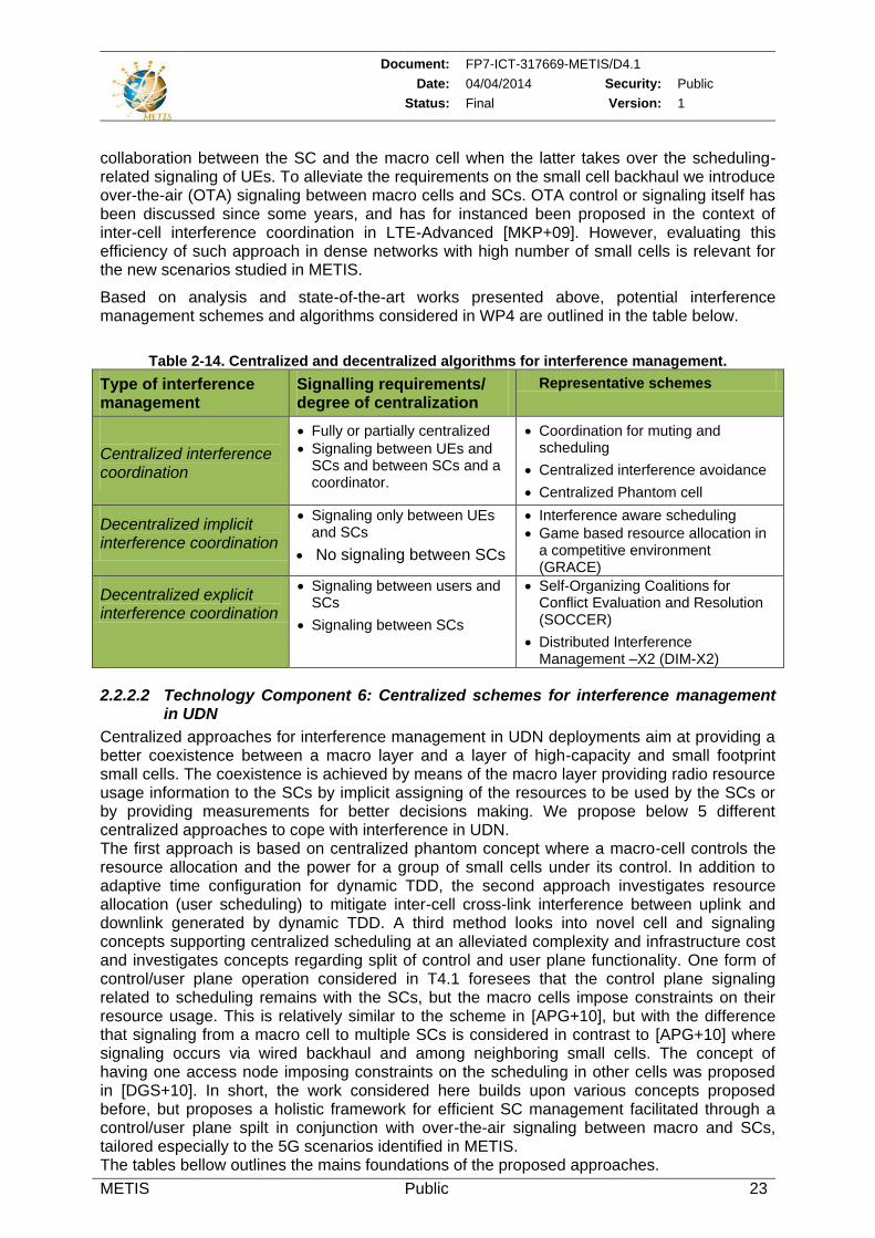
Document: FP7-ICT-317669-METIS/D4.1
Date: 04/04/2014 Security: Public
Status: Final Version: 1
METIS Public 23
collaboration between the SC and the macro cell when the latter takes over the scheduling-related signaling of UEs. To alleviate the requirements on the small cell backhaul we introduce over-the-air (OTA) signaling between macro cells and SCs. OTA control or signaling itself has been discussed since some years, and has for instanced been proposed in the context of inter-cell interference coordination in LTE-Advanced [MKP+09]. However, evaluating this efficiency of such approach in dense networks with high number of small cells is relevant for the new scenarios studied in METIS.
Based on analysis and state-of-the-art works presented above, potential interference management schemes and algorithms considered in WP4 are outlined in the table below.
Table 2-14. Centralized and decentralized algorithms for interference management.
Type of interference management
Signalling requirements/ degree of centralization
Representative schemes
Centralized interference coordination
Fully or partially centralized
Signaling between UEs and SCs and between SCs and a coordinator.
Coordination for muting and scheduling
Centralized interference avoidance
Centralized Phantom cell
Decentralized implicit interference coordination
Signaling only between UEs and SCs
No signaling between SCs
Interference aware scheduling
Game based resource allocation in a competitive environment (GRACE)
Decentralized explicit interference coordination
Signaling between users and SCs
Signaling between SCs
Self-Organizing Coalitions for Conflict Evaluation and Resolution (SOCCER)
Distributed Interference Management –X2 (DIM-X2)
2.2.2.2 Technology Component 6: Centralized schemes for interference management in UDN
Centralized approaches for interference management in UDN deployments aim at providing a better coexistence between a macro layer and a layer of high-capacity and small footprint small cells. The coexistence is achieved by means of the macro layer providing radio resource usage information to the SCs by implicit assigning of the resources to be used by the SCs or by providing measurements for better decisions making. We propose below 5 different centralized approaches to cope with interference in UDN. The first approach is based on centralized phantom concept where a macro-cell controls the resource allocation and the power for a group of small cells under its control. In addition to adaptive time configuration for dynamic TDD, the second approach investigates resource allocation (user scheduling) to mitigate inter-cell cross-link interference between uplink and downlink generated by dynamic TDD. A third method looks into novel cell and signaling concepts supporting centralized scheduling at an alleviated complexity and infrastructure cost and investigates concepts regarding split of control and user plane functionality. One form of control/user plane operation considered in T4.1 foresees that the control plane signaling related to scheduling remains with the SCs, but the macro cells impose constraints on their resource usage. This is relatively similar to the scheme in [APG+10], but with the difference that signaling from a macro cell to multiple SCs is considered in contrast to [APG+10] where signaling occurs via wired backhaul and among neighboring small cells. The concept of having one access node imposing constraints on the scheduling in other cells was proposed in [DGS+10]. In short, the work considered here builds upon various concepts proposed before, but proposes a holistic framework for efficient SC management facilitated through a control/user plane spilt in conjunction with over-the-air signaling between macro and SCs, tailored especially to the 5G scenarios identified in METIS. The tables bellow outlines the mains foundations of the proposed approaches.
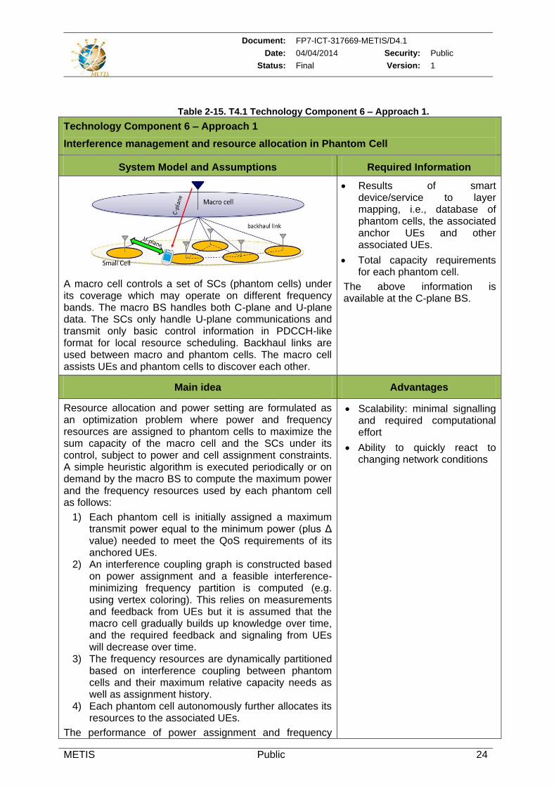
Document: FP7-ICT-317669-METIS/D4.1
Date: 04/04/2014 Security: Public
Status: Final Version: 1
METIS Public 24
Table 2-15. T4.1 Technology Component 6 – Approach 1.
Technology Component 6 – Approach 1
Interference management and resource allocation in Phantom Cell
System Model and Assumptions Required Information
A macro cell controls a set of SCs (phantom cells) under its coverage which may operate on different frequency bands. The macro BS handles both C-plane and U-plane data. The SCs only handle U-plane communications and transmit only basic control information in PDCCH-like format for local resource scheduling. Backhaul links are used between macro and phantom cells. The macro cell assists UEs and phantom cells to discover each other.
Results of smart device/service to layer mapping, i.e., database of phantom cells, the associated anchor UEs and other associated UEs.
Total capacity requirements for each phantom cell.
The above information is available at the C-plane BS.
Main idea Advantages
Resource allocation and power setting are formulated as an optimization problem where power and frequency resources are assigned to phantom cells to maximize the sum capacity of the macro cell and the SCs under its control, subject to power and cell assignment constraints. A simple heuristic algorithm is executed periodically or on demand by the macro BS to compute the maximum power and the frequency resources used by each phantom cell as follows:
1) Each phantom cell is initially assigned a maximum transmit power equal to the minimum power (plus Δ value) needed to meet the QoS requirements of its anchored UEs.
2) An interference coupling graph is constructed based on power assignment and a feasible interference-minimizing frequency partition is computed (e.g. using vertex coloring). This relies on measurements and feedback from UEs but it is assumed that the macro cell gradually builds up knowledge over time, and the required feedback and signaling from UEs will decrease over time.
3) The frequency resources are dynamically partitioned based on interference coupling between phantom cells and their maximum relative capacity needs as well as assignment history.
4) Each phantom cell autonomously further allocates its resources to the associated UEs.
The performance of power assignment and frequency
Scalability: minimal signalling and required computational effort
Ability to quickly react to changing network conditions
Document: FP7-ICT-317669-METIS/D4.1
Date: 04/04/2014 Security: Public
Status: Final Version: 1
METIS Public 25
partition schemes for phantom cells are investigated.
Table 2-16. T4.1 Technology Component 6 – Approach 2.
Technology Component 6 – Approach 2
Coordinated fast uplink downlink resource allocation in UDN
System Model and Assumptions Required Information
Small cells in cellular communication. MIMO MMSE/ (interference rejection combining) IRC receiver both at the UE Rx node and at the eNB. Only interference coordination within small cells is considered.
Fast fading channel information from all transmitters to receivers is available at a coordinator, eNBs and UEs (possibly in TDD transmission)
Additional information such as packet deadline, traffic characteristics
Main idea Advantages
This contribution investigates flexible uplink and downlink resource allocation coordination for individual SCs. The results will be used for trade-off analysis on degree of centralization. Considered schemes include
Fully centralized resource allocation using a coordinator, and
Decentralized implicit and explicit coordination based on signaling between neighboring SCs.
Decentralized schemes exploiting flexible dynamic TDD as well as centralized schemes capturing packet deadline and related context information will be investigated. Additionally the application of dynamic TDD for D2D communication will be studied in a holistic setup comprising of multiple SCs.
Improved spectrum utilisation (DL and UL) per cell based on instantaneous traffic and channel conditions. This increases frequency planning / time slot configuration flexibility between UL and DL.
Lower delay in the downlink without noticeable degradation in the uplink (Initial investigation shows 43% performance gain at 95 percentile).
Table 2-17. T4.1 Technology Component 6 – Approach 3.
Technology Component 6 – Approach 3
Framework for control/user plane design with over-the-air signalling for UDN
System Model and Assumptions Required Information
Heterogeneous deployment with high number of SCs per macro. Macro cells and SCs using a low-frequency (e.g. 900 MHz) and high-frequency band (e.g. 2.6 GHz), respectively. Terminals using either both low and high frequency bands or only high frequency band depending on the algorithm variant used.
All channel and buffer information for interference management gathered in centralized points
Main idea Advantages
The main idea is to establish a framework for control/user Network performance close to
Document: FP7-ICT-317669-METIS/D4.1
Date: 04/04/2014 Security: Public
Status: Final Version: 1
METIS Public 26
plane split based on OTA signaling between macro and SCS. Two variants of control/user plane split are initially considered as illustrated in Figure 2-4 above:
Variant 1: all control plane signaling is handled by macro cells, except the signaling connected to link adaptation, HARQ, feedback for beam-forming. This means that the macro cell takes full control of the scheduling for the SCs which overhear the grants issued by the macro cell to take the right action.
Variant 2: all control plane signaling is handled by the SCs which forward channel information to the macro cell that in return defines constraints on the resources which SCs can use for scheduling.
Variant 1 introduces additional delay in downlink scheduling with grants overheard by the SCs and requires all terminals to have connectivity to the macro cell (and two transceivers), which would be an issue for low-cost and low-power devices such as MTC. Variant 2, on the other hand does not have the above issue but generates additional signaling between SCs and macro cell, and it may not be able to respond as quickly to bursty changes in traffic as variant 1 does. Therefore future work will also consider hybrid forms of variants 1 and 2.
fully centralized interference management (all channel and buffer information are gathered in centralized points in the network, and radio resource management is performed under tight centralized control
Reduced infrastructure cost as low-latency logical backhaul connection is not required among SCs or between SCs and BS.
Table 2-18. Technology Component 6 – Approach 4.
Technology Component 6 – Approach 4
Out-of-band advanced block scheduling in heterogeneous networks
System Model and Assumptions Required Information
Mixed macro and small cell scenario. All cells have TDD capabilities. Macro radio resources are underused, even in the busy hour.
Details about radio resources to be used in the next frames are provided by the scheduler of the macro BS
Main idea Advantages
The main idea is to use TDD for coordinating FDD communications among the small cells and the macro layer and provide a synchronization reference for the small cells. More precisely, the LTE TDD air interface is used to send the subframe scheduling from the macro
Coordinated joint sharing of radio resources between macro and SCs
Efficient use of available resources
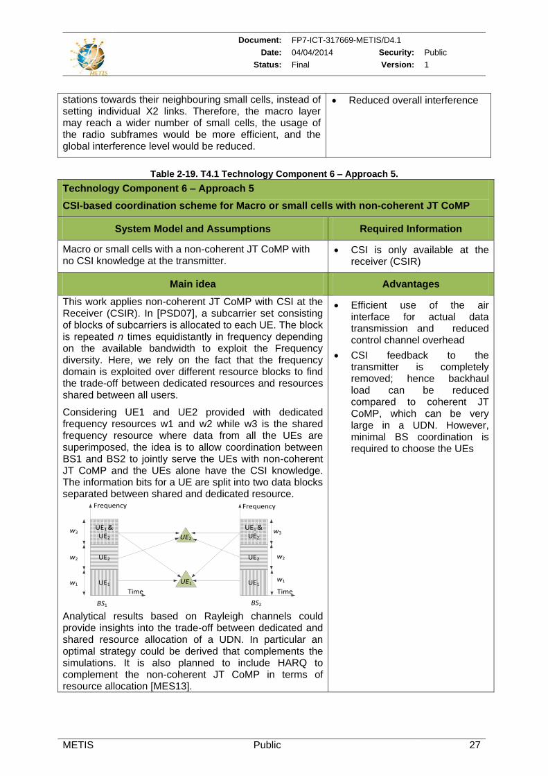
Document: FP7-ICT-317669-METIS/D4.1
Date: 04/04/2014 Security: Public
Status: Final Version: 1
METIS Public 27
stations towards their neighbouring small cells, instead of setting individual X2 links. Therefore, the macro layer may reach a wider number of small cells, the usage of the radio subframes would be more efficient, and the global interference level would be reduced.
Reduced overall interference
Table 2-19. T4.1 Technology Component 6 – Approach 5.
Technology Component 6 – Approach 5
CSI-based coordination scheme for Macro or small cells with non-coherent JT CoMP
System Model and Assumptions Required Information
Macro or small cells with a non-coherent JT CoMP with no CSI knowledge at the transmitter.
CSI is only available at the receiver (CSIR)
Main idea Advantages
This work applies non-coherent JT CoMP with CSI at the Receiver (CSIR). In [PSD07], a subcarrier set consisting of blocks of subcarriers is allocated to each UE. The block is repeated n times equidistantly in frequency depending on the available bandwidth to exploit the Frequency diversity. Here, we rely on the fact that the frequency domain is exploited over different resource blocks to find the trade-off between dedicated resources and resources shared between all users.
Considering UE1 and UE2 provided with dedicated frequency resources w1 and w2 while w3 is the shared frequency resource where data from all the UEs are superimposed, the idea is to allow coordination between BS1 and BS2 to jointly serve the UEs with non-coherent JT CoMP and the UEs alone have the CSI knowledge. The information bits for a UE are split into two data blocks separated between shared and dedicated resource.
Frequency
Time
UE1
UE2
UE1 & UE2
w3
w2
w1
Frequency
Time
UE1
UE2
UE1 & UE2
w3
w2
w1
BS1 BS2
UE2
UE1
Analytical results based on Rayleigh channels could provide insights into the trade-off between dedicated and shared resource allocation of a UDN. In particular an optimal strategy could be derived that complements the simulations. It is also planned to include HARQ to complement the non-coherent JT CoMP in terms of resource allocation [MES13].
Efficient use of the air interface for actual data transmission and reduced control channel overhead
CSI feedback to the transmitter is completely removed; hence backhaul load can be reduced compared to coherent JT CoMP, which can be very large in a UDN. However, minimal BS coordination is required to choose the UEs
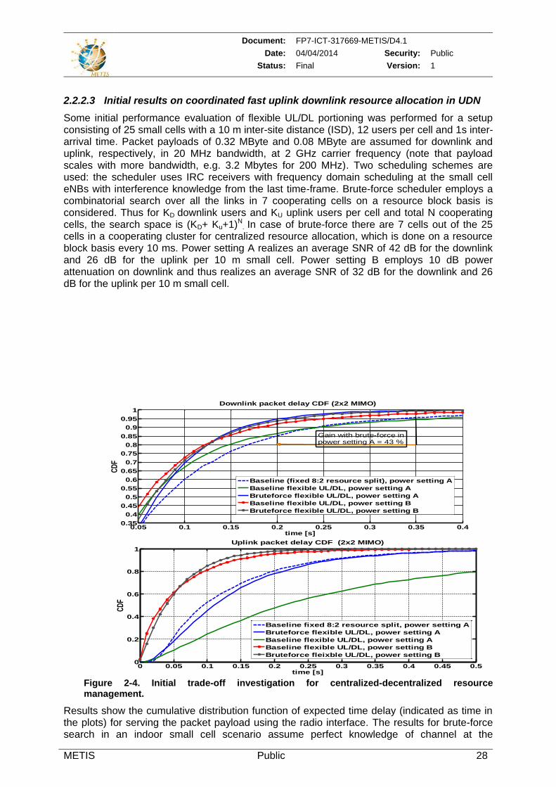
Document: FP7-ICT-317669-METIS/D4.1
Date: 04/04/2014 Security: Public
Status: Final Version: 1
METIS Public 28
2.2.2.3 Initial results on coordinated fast uplink downlink resource allocation in UDN
Some initial performance evaluation of flexible UL/DL portioning was performed for a setup consisting of 25 small cells with a 10 m inter-site distance (ISD), 12 users per cell and 1s inter-arrival time. Packet payloads of 0.32 MByte and 0.08 MByte are assumed for downlink and uplink, respectively, in 20 MHz bandwidth, at 2 GHz carrier frequency (note that payload scales with more bandwidth, e.g. 3.2 Mbytes for 200 MHz). Two scheduling schemes are used: the scheduler uses IRC receivers with frequency domain scheduling at the small cell eNBs with interference knowledge from the last time-frame. Brute-force scheduler employs a combinatorial search over all the links in 7 cooperating cells on a resource block basis is considered. Thus for KD downlink users and KU uplink users per cell and total N cooperating cells, the search space is (KD+ Ku+1)N
. In case of brute-force there are 7 cells out of the 25 cells in a cooperating cluster for centralized resource allocation, which is done on a resource block basis every 10 ms. Power setting A realizes an average SNR of 42 dB for the downlink and 26 dB for the uplink per 10 m small cell. Power setting B employs 10 dB power attenuation on downlink and thus realizes an average SNR of 32 dB for the downlink and 26 dB for the uplink per 10 m small cell.
0.05 0.1 0.15 0.2 0.25 0.3 0.35 0.40.35
0.4
0.45
0.5
0.55
0.6
0.65
0.7
0.75
0.8
0.85
0.9
0.95
1Downlink packet delay CDF (2x2 MIMO)
time [s]
CD
F
Baseline (fixed 8:2 resource split), power setting A
Baseline flexible UL/DL, power setting A
Bruteforce flexible UL/DL, power setting A
Baseline flexible UL/DL, power setting B
Bruteforce flexible UL/DL, power setting B
Gain with brute-force inpower setting A = 43 %
0 0.05 0.1 0.15 0.2 0.25 0.3 0.35 0.4 0.45 0.50
0.2
0.4
0.6
0.8
1Uplink packet delay CDF (2x2 MIMO)
time [s]
CD
F
Baseline fixed 8:2 resource split, power setting A
Bruteforce flexible UL/DL, power setting A
Baseline flexible UL/DL, power setting A
Baseline flexible UL/DL, power setting B
Bruteforce fleixble UL/DL, power setting B
Figure 2-4. Initial trade-off investigation for centralized-decentralized resource management.
Results show the cumulative distribution function of expected time delay (indicated as time in the plots) for serving the packet payload using the radio interface. The results for brute-force search in an indoor small cell scenario assume perfect knowledge of channel at the
Document: FP7-ICT-317669-METIS/D4.1
Date: 04/04/2014 Security: Public
Status: Final Version: 1
METIS Public 29
coordinator, which serves as an upper bound evaluated through simulations. A radio layer delay minimizing scheduler is employed for all the schemes. The baseline scheduler assumes no exchange of channel information between access points or to a coordinator however it makes use of interference knowledge from the last time frame based on feedbacks from each UE to its associated SC. Results are shown in Figure 2-3 (for DL and UL).
In case of power setting A, a downlink delay reduction of 43% in 95 percentile is realized with brute-force scheme using flexible uplink downlink allocation as compared to baseline scheduler (either fixed or flexible split). The uplink does not suffer any noticeable degradation upon using the brute-force scheduler, while the baseline flexible UL/DL undergoes a severe performance loss due to interference conditions. In case of power setting B, with flexible UL/DL allocation, the downlink realizes a delay reduction of 29% using baseline scheduler as compared to a baseline with fixed 8:2 split of resources. For this power setting, uplink realizes a gain of roughly 100% using baseline UL/DL scheduler as compared to fixed split of resources. For this power setting, the brute-force search realizes a downlink delay reduction of 12.5% at 95 percentile in power setting B compared to the baseline scheduler with flexible uplink and downlink split.
2.2.2.4 Technology Component 7: Decentralized and hybrid Schemes for Interference Management in UDN
Several decentralized/distributed interference management schemes were proposed in the literature for heterogeneous deployments [EHB08], [CCK+10], [GCC+10], [AKG11]. Modifications of existing schemes as well as new proposals are considered in T4.1 to address two main motivations: a) densification of small cells and b) better capture the traffic load burstiness in diverse scenarios. The tables bellow introduce two new decentralized approaches to allocate dynamically resources to femto-cells taking into account interference level changes.
Table 2-20. T4.1 Technology Component 7 – Approach 1.
Technology Component 7 – Approach 1
Time-sharing interference mitigation using resource auctioning and regret-matching learning
System Model and Assumptions Required Information
Heterogeneous scenario with femto-cells operating in-band or out-band with macro-cells. At most one cellular UE can be allocated on a PRB per BS (i.e. intra-cell orthogonality maintained). Ideal wireline backhaul is assumed.
Slow fading CSI (path loss and shadowing) for all links available at all transmitters
Information on interference power distribution per user in frequency and space domains for each BS.
Main idea Advantages
This technique tries to mitigate interference using the correlated Equilibrium approach, in which each player considers the behaviours of other users to explore mutual benefits [Aum74]. One of the key points is to define strategies available to all players (BSs) which can be based on different approaches including for examples:
- Sharing of resources in time and frequency using schemes such as fractional frequency reuse (FFR) or soft frequency reuse (SFR);
No central entity is required: each BS executes the algorithm and calculates the time-sharing coefficients by itself.
A network-wise optimization: uses of multi-cell channel knowledge to obtain the time-sharing coefficients for all strategies.
Flexibility: by changing the set of
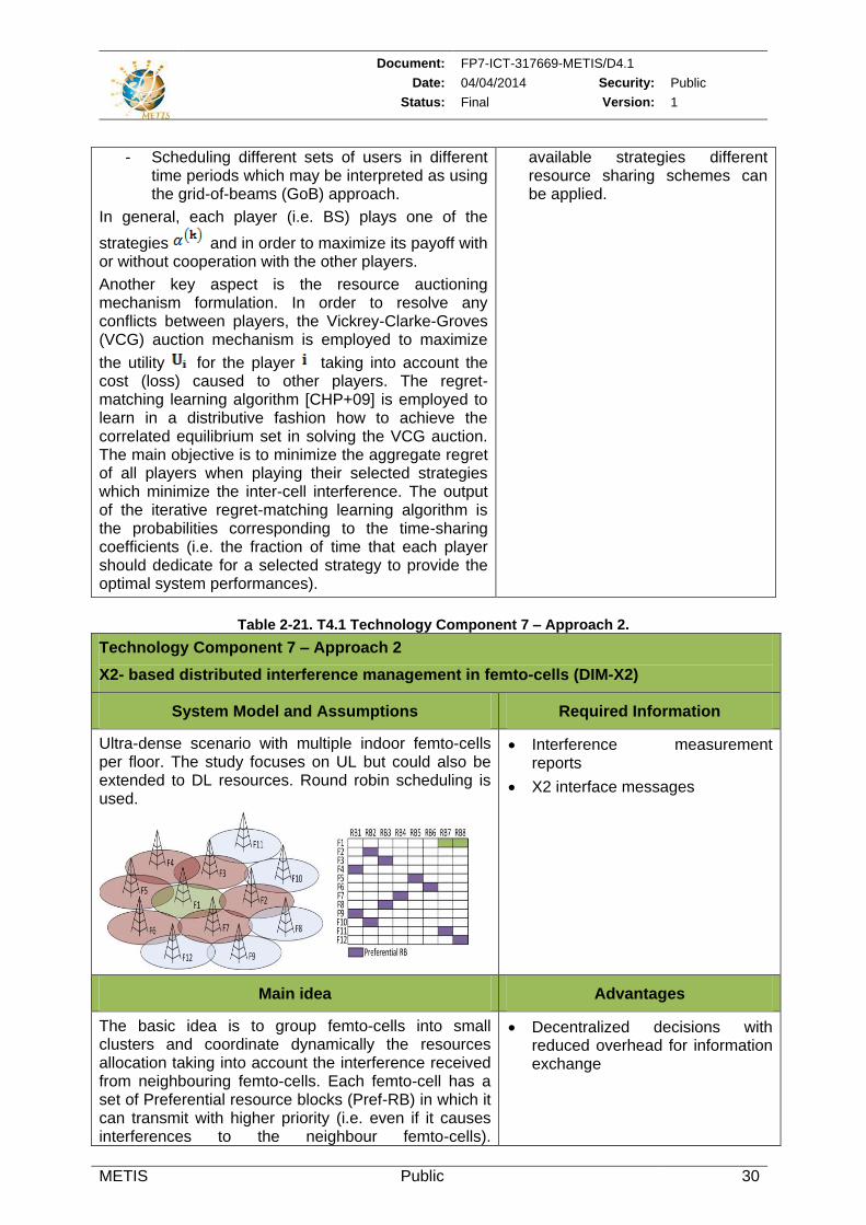
Document: FP7-ICT-317669-METIS/D4.1
Date: 04/04/2014 Security: Public
Status: Final Version: 1
METIS Public 30
- Scheduling different sets of users in different time periods which may be interpreted as using the grid-of-beams (GoB) approach.
In general, each player (i.e. BS) plays one of the
strategies and in order to maximize its payoff with or without cooperation with the other players.
Another key aspect is the resource auctioning mechanism formulation. In order to resolve any conflicts between players, the Vickrey-Clarke-Groves (VCG) auction mechanism is employed to maximize
the utility for the player taking into account the cost (loss) caused to other players. The regret-matching learning algorithm [CHP+09] is employed to learn in a distributive fashion how to achieve the correlated equilibrium set in solving the VCG auction. The main objective is to minimize the aggregate regret of all players when playing their selected strategies which minimize the inter-cell interference. The output of the iterative regret-matching learning algorithm is the probabilities corresponding to the time-sharing coefficients (i.e. the fraction of time that each player should dedicate for a selected strategy to provide the optimal system performances).
available strategies different resource sharing schemes can be applied.
Table 2-21. T4.1 Technology Component 7 – Approach 2.
Technology Component 7 – Approach 2
X2- based distributed interference management in femto-cells (DIM-X2)
System Model and Assumptions Required Information
Ultra-dense scenario with multiple indoor femto-cells per floor. The study focuses on UL but could also be extended to DL resources. Round robin scheduling is used.
Interference measurement reports
X2 interface messages
Main idea Advantages
The basic idea is to group femto-cells into small clusters and coordinate dynamically the resources allocation taking into account the interference received from neighbouring femto-cells. Each femto-cell has a set of Preferential resource blocks (Pref-RB) in which it can transmit with higher priority (i.e. even if it causes interferences to the neighbour femto-cells).
Decentralized decisions with reduced overhead for information exchange
Document: FP7-ICT-317669-METIS/D4.1
Date: 04/04/2014 Security: Public
Status: Final Version: 1
METIS Public 31
Neighbouring femto-cells may use these RBs if they don’t deteriorate its performances. Different Pref-RBs are chosen dynamically for femto-cells belonging to the
same cluster . Once a femto-cell is switched on, it
monitors the channel and creates cluster including its neighbour cells with a measured power above a
given threshold . Then, it requests other femto-
cells in about their Pref-RB and selects its Pref-RBs
( ) among RBs not being used by other cells or those with low interference level. Information about Pref-RBs is exchanged over X2 interface using HII messages. Two alternatives are proposed for the resource allocation: 1) DIM-X2 Basic: every femto-cell collects
information about RBs used by its neighbours. When the interference level measured in a given
RB is above a certain threshold , the femto-cell sends an IOI message to the neighbour/s generating the interference (i.e. all the neighbours using RB) if this a Pref-RB or stops using it if not.
2) DIM-X2 with UE support (X2-UES): here the users are classified as critical with regards to a cluster N of femto-cells if the received interference power from each of the femto-cells is above a
threshold . The femto-cell allocates resources to UEs according to their classification. A critical UE gets only Pref-RBs which should not be used by any other UE controlled by femto-cells belonging to cluster N. The serving femto-cell communicates the allocation decision to these femto-cells through a HII message in order to prevent them from using these RBs. When UEs are not classified as critical, they can be scheduled in any free available resource.
The performances of X2-UEs and DIM-X2 Basic algorithms are evaluated in a UDN scenario with 60 femto-cells uniformly distributed in a floor of 50x150 m2. The Figure 2-5 below shows the gains in terms of throughput per user when using DIM-X2 Basic and especially X2-UEs algorithms compared to case where no ICIC used.
1 2 3 4 5 6 7 8 9 100
0.5
1
1.5
2
2.5
3
3.5
Number of UEs per femtocell
To
tal
thro
ug
hp
ut
per
UE
(M
bp
s)
X2-UEs
X2-Basic
no ICIC
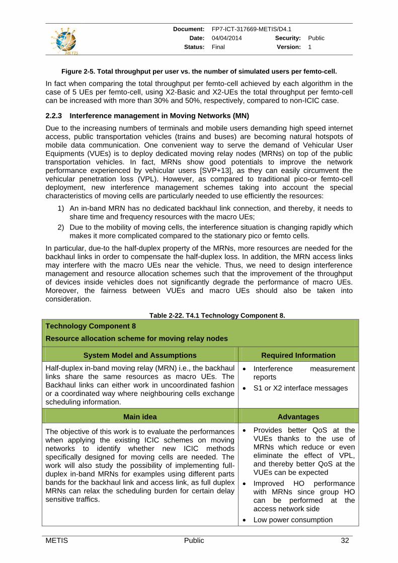
Document: FP7-ICT-317669-METIS/D4.1
Date: 04/04/2014 Security: Public
Status: Final Version: 1
METIS Public 32
Figure 2-5. Total throughput per user vs. the number of simulated users per femto-cell.
In fact when comparing the total throughput per femto-cell achieved by each algorithm in the case of 5 UEs per femto-cell, using X2-Basic and X2-UEs the total throughput per femto-cell can be increased with more than 30% and 50%, respectively, compared to non-ICIC case.
2.2.3 Interference management in Moving Networks (MN)
Due to the increasing numbers of terminals and mobile users demanding high speed internet access, public transportation vehicles (trains and buses) are becoming natural hotspots of mobile data communication. One convenient way to serve the demand of Vehicular User Equipments (VUEs) is to deploy dedicated moving relay nodes (MRNs) on top of the public transportation vehicles. In fact, MRNs show good potentials to improve the network performance experienced by vehicular users [SVP+13], as they can easily circumvent the vehicular penetration loss (VPL). However, as compared to traditional pico-or femto-cell deployment, new interference management schemes taking into account the special characteristics of moving cells are particularly needed to use efficiently the resources:
1) An in-band MRN has no dedicated backhaul link connection, and thereby, it needs to share time and frequency resources with the macro UEs;
2) Due to the mobility of moving cells, the interference situation is changing rapidly which makes it more complicated compared to the stationary pico or femto cells.
In particular, due-to the half-duplex property of the MRNs, more resources are needed for the backhaul links in order to compensate the half-duplex loss. In addition, the MRN access links may interfere with the macro UEs near the vehicle. Thus, we need to design interference management and resource allocation schemes such that the improvement of the throughput of devices inside vehicles does not significantly degrade the performance of macro UEs. Moreover, the fairness between VUEs and macro UEs should also be taken into consideration.
Table 2-22. T4.1 Technology Component 8.
Technology Component 8
Resource allocation scheme for moving relay nodes
System Model and Assumptions Required Information
Half-duplex in-band moving relay (MRN) i.e., the backhaul links share the same resources as macro UEs. The Backhaul links can either work in uncoordinated fashion or a coordinated way where neighbouring cells exchange scheduling information.
Interference measurement reports
S1 or X2 interface messages
Main idea Advantages
The objective of this work is to evaluate the performances when applying the existing ICIC schemes on moving networks to identify whether new ICIC methods specifically designed for moving cells are needed. The work will also study the possibility of implementing full-duplex in-band MRNs for examples using different parts bands for the backhaul link and access link, as full duplex MRNs can relax the scheduling burden for certain delay sensitive traffics.
Provides better QoS at the VUEs thanks to the use of MRNs which reduce or even eliminate the effect of VPL, and thereby better QoS at the VUEs can be expected
Improved HO performance with MRNs since group HO can be performed at the access network side
Low power consumption
Document: FP7-ICT-317669-METIS/D4.1
Date: 04/04/2014 Security: Public
Status: Final Version: 1
METIS Public 33
3 Demand, traffic, and mobility management
T4.2 looks into efficient exploitation of resources offered by heterogeneous networks in order to provide better network performance for end users with dynamic service demands and high mobility. More specifically, network level concepts that support the novel services and diverse requirements emerging from METIS scenarios and HTs will be investigated via two topics:
Smart device/service to RAT/layer mapping, which exploits available/or predicted context information such as location, user behavior or the capabilities of devices to define efficient resource mapping in a multi-layer and multi-RAT environment. In addition, novel architecture concepts will be introduced to adaptively assign device/service to the appropriate layer that meets its requirements.
Smart signaling for mobility, which focus on mobility related signaling and exploit context information to optimize the handovers in the same RAT or between different RATs.
Through research activities partners are planning to exploit a variety of context information that could be collected from the user’s environment, devices, services etc., and processed in order to optimize the decision making. Thus, the efficiency of the proposed solutions will depend on the context information used and the accuracy of methods used for predictions. Initial approaches using the context information are presented in the following sections to show the benefit of context awareness in service/layer mapping as well as for mobility enhancement. To this end, research works to build up the context information are carried out and described in section 3.1. Then the research activities related to smart device/service to RAT/layer mapping and smart signalling for mobility are introduced in section 3.2 and 3.3, respectively.
3.1 Building context awareness
The exploitation of context information, such as location, device capability or user profile, will facilitate the efficient network resource mapping, the mobility management and the signalling reduction. This section describes the proposed general concepts and methodologies enabling such context awareness in wireless and mobile systems.
3.1.1 State-of-the-art
The exploitation of context information and the context awareness were originally investigated in the area of pervasive computing where relevant information from the environment, such as location and user identity, is collected and provided to the computing system to adapt to the corresponding applications accordingly. Recently, the concept of context awareness has been extended to the mobile and wireless systems in order to make them able to adapt their configurations (actions) to the changing physical and application environment. According to [PDC12], the essential functionalities of a context-aware wireless and mobile system can be summed up in six groups: context acquisition, context modelling, context exchange, context evaluation, exploitation of context from business logic perspective and security/privacy/trust horizontal functionality.
Diverse frameworks were introduced for the implementation of context-awareness. Most of them were designed for a particular application area, e.g. vertical handover [XPG+11] [HNH07] [BWK+07] [KMS+11] [BCG11] or internet of thing [YMF11]. More general frameworks were described in [PJJ+03] [HH05] [NMB+09].
Document: FP7-ICT-317669-METIS/D4.1
Date: 04/04/2014 Security: Public
Status: Final Version: 1
METIS Public 34
3.1.2 Definition and taxonomy of context information
Definition:
- Context information is the information enabling the perception of states and situations of network entities (e.g., network nodes, terminals, users, etc.) and their interactive relations.
- A context-aware radio network is a network which utilizes the context information to assist its operation and optimization without explicit interaction with its users.
According to the above definition, the context information in our research scope can be defined in a very wide sense and includes a variety of information. For a systematic and well-ordered research work we further divided based on the following criteria:
The relation to network entities: - UE context information: the information collected from the UE, e.g., position,
speed, device capability, UE battery status, UE settings, user profiles, buffer status etc.;
- Context information of network layer and lower: e.g., radio propagation map, current or historical interference status, network load;
- Context information of higher layer: e.g., QoS requirement of the applications and services, service profile.
The levels of abstraction: - Primary context information: information that can be measured or collected from
the network directly, e.g. GPS position; - Secondary context information: the knowledge that needs to be inferred from the
primary context information, e.g., energy efficiency, UE behavior pattern, traffic pattern.
The time scale: - Static information: e.g. UE capability; - Quasi-static information: e.g., UE settings, handover history; - Dynamic information: e.g., UE location, traffic expectations.
3.1.3 Technology Component 1: Optimized distribution scheme for context information between the network entities
For the future wireless and mobile networks, we consider a broad range of context information, such as user position, velocity, radio propagation map, profile of the current and upcoming services. Pieces of context information are collected from different network entities which are placed at different positions and layers of the network. The information from different sources has to be aggregated before it can be used to support the decision making process. Considering the amount and the variety of the context information, the design of an efficient management and exchange mechanism for the context information is one of the challenging tasks handled in this project.
Document: FP7-ICT-317669-METIS/D4.1
Date: 04/04/2014 Security: Public
Status: Final Version: 1
METIS Public 35
Table 3-1. T4.2 Technology Component 1.
Technology Component 1
Optimized distribution scheme for context information
System Model and Assumptions Required Information
Generic cellular network supporting multi-RAT and multi-layer architecture. Additional signalling channels are available for the exchange of context information. Exchange of context information between different network layers is supported
The CAPEX cost function for the deployment and implementation of the corresponding context-aware functionality
The OPEX cost function to execute the functionality regarding the computing cost and power consumption
The required data rate to exchange of raw and modelled context information and the exchange of control signalling
Main idea Advantages
As a generic approach we model the design problem as a nested optimization problem. We consider four fundamental functionalities of a context-aware system: the acquisition, the exchange and the modeling of the context information, and the final decision making by exploiting the context information. The deployment of those functional entities impacts the capital and operational expenditure of the system, which is optimized by the proposed solution. (Details of the optimization function are given in Appendix 7.3).
Since the option for selecting the location to implement the functional entities are a finite set, brute-force method can be used to find the optimum solution once the data rate of exchanged information between each functional entity is known. Based on the state-of-the-art and the recent technical achievement in this project, the maximum data rate of exchanged context information can be derived for certain kinds of context information, e.g. location. However, there is a trade-off between the minimum necessary amount of information exchange and the achievable performance gain in the network by exploiting context information. In the further stage of the project we plan to analyze this trade-off and consider the impact in the optimization problem.
Achieve the optimal deployment strategy for context-aware systems
Provide general methodology applicable for both centralized and distributed architecture
3.1.4 Prediction methods for context information
Prediction of relevant context data based on history information and user/service profile can be used as a means for acquisition and exploitation of context information. In the following section, we propose a new method for the movement prediction that is useful for mobility handling.
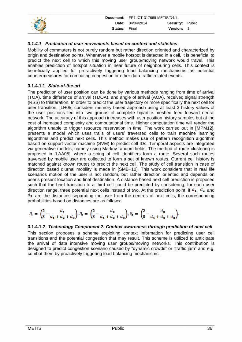
Document: FP7-ICT-317669-METIS/D4.1
Date: 04/04/2014 Security: Public
Status: Final Version: 1
METIS Public 36
3.1.4.1 Prediction of user movements based on context and statistics
Mobility of commuters is not purely random but rather direction oriented and characterized by origin and destination points. Whenever a mobile hotspot is detected in a cell, it is beneficial to predict the next cell to which this moving user group/moving network would travel. This enables prediction of hotspot situation in near future of neighbouring cells. This context is beneficially applied for pro-actively triggering load balancing mechanisms as potential countermeasures for combating congestion or other data traffic related events.
3.1.4.1.1 State-of-the-art
The prediction of user position can be done by various methods ranging from time of arrival (TOA), time difference of arrival (TDOA), and angle of arrival (AOA), received signal strength (RSS) to trilateration. In order to predict the user trajectory or more specifically the next cell for user transition, [LH05] considers memory based approach using at least 3 history values of the user positions fed into two groups of complete bipartite meshed feed forward neural network. The accuracy of this approach increases with user position history samples but at the cost of increased complexity and computational time. Higher computation time will render the algorithm unable to trigger resource reservation in time. The work carried out in [MPM12], presents a model which uses trails of users’ traversed cells to train machine learning algorithms and predict next cells. This method makes use of pattern recognition algorithm based on support vector machine (SVM) to predict cell IDs. Temporal aspects are integrated via generative models, namely using Markov random fields. The method of route clustering is proposed in [LAA05], where a string of cell identifiers form a route. Several such routes traversed by mobile user are collected to form a set of known routes. Current cell history is matched against known routes to predict the next cell. The study of cell transition in case of direction based diurnal mobility is made in [SMB+10]. This work considers that in real life scenarios motion of the user is not random, but rather direction oriented and depends on user’s present location and final destination. A distance based next cell prediction is proposed such that the brief transition to a third cell could be predicted by considering, for each user
direction range, three potential next cells instead of two. At the prediction point, if , and
are the distances separating the user from the centres of next cells, the corresponding probabilities based on distances are as follows:
3.1.4.1.2 Technology Component 2: Context awareness through prediction of next cell
This section proposes a scheme exploiting context information for predicting user cell transitions and the potential congestion that may result. This scheme is utilized to anticipate the arrival of data intensive moving user groups/moving networks. This contribution is designed to predict congestion scenario caused by “dynamic crowds” or “traffic jam” and e.g. combat them by proactively triggering load balancing mechanisms.
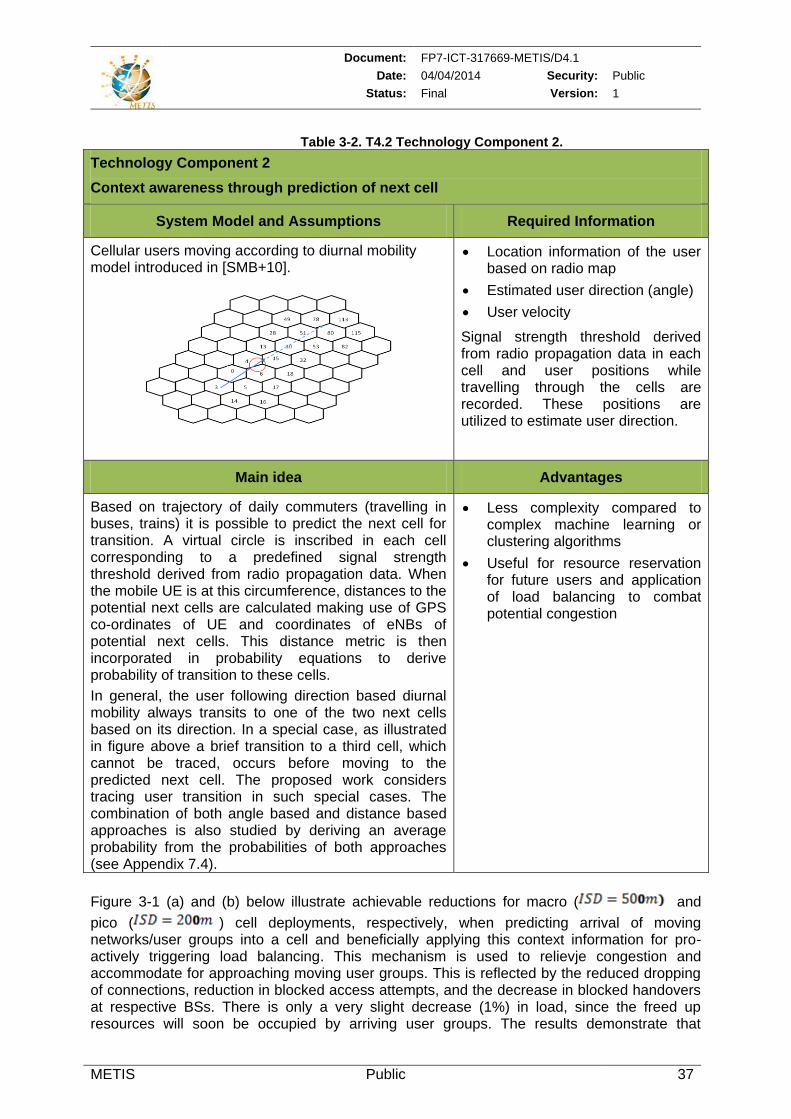
Document: FP7-ICT-317669-METIS/D4.1
Date: 04/04/2014 Security: Public
Status: Final Version: 1
METIS Public 37
Table 3-2. T4.2 Technology Component 2.
Technology Component 2
Context awareness through prediction of next cell
System Model and Assumptions Required Information
Cellular users moving according to diurnal mobility model introduced in [SMB+10].
Location information of the user based on radio map
Estimated user direction (angle)
User velocity
Signal strength threshold derived from radio propagation data in each cell and user positions while travelling through the cells are recorded. These positions are utilized to estimate user direction.
Main idea Advantages
Based on trajectory of daily commuters (travelling in buses, trains) it is possible to predict the next cell for transition. A virtual circle is inscribed in each cell corresponding to a predefined signal strength threshold derived from radio propagation data. When the mobile UE is at this circumference, distances to the potential next cells are calculated making use of GPS co-ordinates of UE and coordinates of eNBs of potential next cells. This distance metric is then incorporated in probability equations to derive probability of transition to these cells.
In general, the user following direction based diurnal mobility always transits to one of the two next cells based on its direction. In a special case, as illustrated in figure above a brief transition to a third cell, which cannot be traced, occurs before moving to the predicted next cell. The proposed work considers tracing user transition in such special cases. The combination of both angle based and distance based approaches is also studied by deriving an average probability from the probabilities of both approaches (see Appendix 7.4).
Less complexity compared to complex machine learning or clustering algorithms
Useful for resource reservation for future users and application of load balancing to combat potential congestion
Figure 3-1 (a) and (b) below illustrate achievable reductions for macro ( and
pico ( ) cell deployments, respectively, when predicting arrival of moving networks/user groups into a cell and beneficially applying this context information for pro-actively triggering load balancing. This mechanism is used to relievje congestion and accommodate for approaching moving user groups. This is reflected by the reduced dropping of connections, reduction in blocked access attempts, and the decrease in blocked handovers at respective BSs. There is only a very slight decrease (1%) in load, since the freed up resources will soon be occupied by arriving user groups. The results demonstrate that
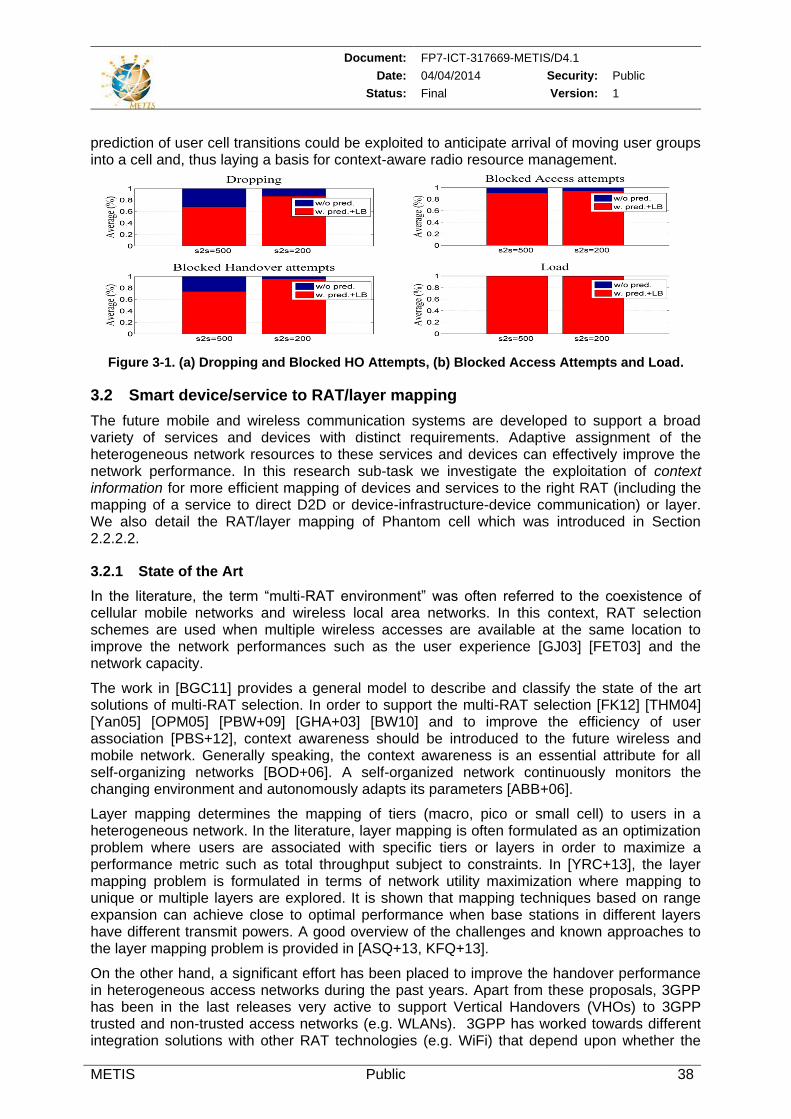
Document: FP7-ICT-317669-METIS/D4.1
Date: 04/04/2014 Security: Public
Status: Final Version: 1
METIS Public 38
prediction of user cell transitions could be exploited to anticipate arrival of moving user groups into a cell and, thus laying a basis for context-aware radio resource management.
Figure 3-1. (a) Dropping and Blocked HO Attempts, (b) Blocked Access Attempts and Load.
3.2 Smart device/service to RAT/layer mapping
The future mobile and wireless communication systems are developed to support a broad variety of services and devices with distinct requirements. Adaptive assignment of the heterogeneous network resources to these services and devices can effectively improve the network performance. In this research sub-task we investigate the exploitation of context information for more efficient mapping of devices and services to the right RAT (including the mapping of a service to direct D2D or device-infrastructure-device communication) or layer. We also detail the RAT/layer mapping of Phantom cell which was introduced in Section 2.2.2.2.
3.2.1 State of the Art
In the literature, the term “multi-RAT environment” was often referred to the coexistence of cellular mobile networks and wireless local area networks. In this context, RAT selection schemes are used when multiple wireless accesses are available at the same location to improve the network performances such as the user experience [GJ03] [FET03] and the network capacity.
The work in [BGC11] provides a general model to describe and classify the state of the art solutions of multi-RAT selection. In order to support the multi-RAT selection [FK12] [THM04] [Yan05] [OPM05] [PBW+09] [GHA+03] [BW10] and to improve the efficiency of user association [PBS+12], context awareness should be introduced to the future wireless and mobile network. Generally speaking, the context awareness is an essential attribute for all self-organizing networks [BOD+06]. A self-organized network continuously monitors the changing environment and autonomously adapts its parameters [ABB+06].
Layer mapping determines the mapping of tiers (macro, pico or small cell) to users in a heterogeneous network. In the literature, layer mapping is often formulated as an optimization problem where users are associated with specific tiers or layers in order to maximize a performance metric such as total throughput subject to constraints. In [YRC+13], the layer mapping problem is formulated in terms of network utility maximization where mapping to unique or multiple layers are explored. It is shown that mapping techniques based on range expansion can achieve close to optimal performance when base stations in different layers have different transmit powers. A good overview of the challenges and known approaches to the layer mapping problem is provided in [ASQ+13, KFQ+13].
On the other hand, a significant effort has been placed to improve the handover performance in heterogeneous access networks during the past years. Apart from these proposals, 3GPP has been in the last releases very active to support Vertical Handovers (VHOs) to 3GPP trusted and non-trusted access networks (e.g. WLANs). 3GPP has worked towards different integration solutions with other RAT technologies (e.g. WiFi) that depend upon whether the
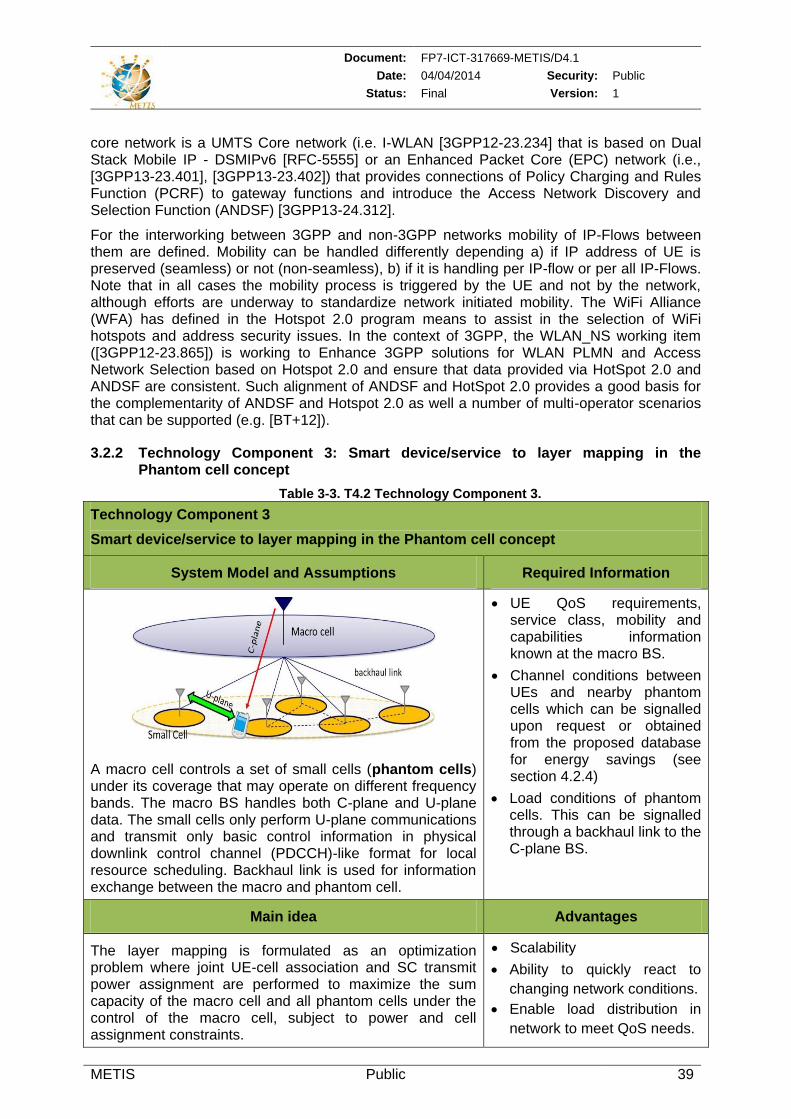
Document: FP7-ICT-317669-METIS/D4.1
Date: 04/04/2014 Security: Public
Status: Final Version: 1
METIS Public 39
core network is a UMTS Core network (i.e. I-WLAN [3GPP12-23.234] that is based on Dual Stack Mobile IP - DSMIPv6 [RFC-5555] or an Enhanced Packet Core (EPC) network (i.e., [3GPP13-23.401], [3GPP13-23.402]) that provides connections of Policy Charging and Rules Function (PCRF) to gateway functions and introduce the Access Network Discovery and Selection Function (ANDSF) [3GPP13-24.312].
For the interworking between 3GPP and non-3GPP networks mobility of IP-Flows between them are defined. Mobility can be handled differently depending a) if IP address of UE is preserved (seamless) or not (non-seamless), b) if it is handling per IP-flow or per all IP-Flows. Note that in all cases the mobility process is triggered by the UE and not by the network, although efforts are underway to standardize network initiated mobility. The WiFi Alliance (WFA) has defined in the Hotspot 2.0 program means to assist in the selection of WiFi hotspots and address security issues. In the context of 3GPP, the WLAN_NS working item ([3GPP12-23.865]) is working to Enhance 3GPP solutions for WLAN PLMN and Access Network Selection based on Hotspot 2.0 and ensure that data provided via HotSpot 2.0 and ANDSF are consistent. Such alignment of ANDSF and HotSpot 2.0 provides a good basis for the complementarity of ANDSF and Hotspot 2.0 as well a number of multi-operator scenarios that can be supported (e.g. [BT+12]).
3.2.2 Technology Component 3: Smart device/service to layer mapping in the Phantom cell concept
Table 3-3. T4.2 Technology Component 3.
Technology Component 3
Smart device/service to layer mapping in the Phantom cell concept
System Model and Assumptions Required Information
A macro cell controls a set of small cells (phantom cells) under its coverage that may operate on different frequency bands. The macro BS handles both C-plane and U-plane data. The small cells only perform U-plane communications and transmit only basic control information in physical downlink control channel (PDCCH)-like format for local resource scheduling. Backhaul link is used for information exchange between the macro and phantom cell.
UE QoS requirements, service class, mobility and capabilities information known at the macro BS.
Channel conditions between UEs and nearby phantom cells which can be signalled upon request or obtained from the proposed database for energy savings (see section 4.2.4)
Load conditions of phantom cells. This can be signalled through a backhaul link to the C-plane BS.
Main idea Advantages
The layer mapping is formulated as an optimization problem where joint UE-cell association and SC transmit power assignment are performed to maximize the sum capacity of the macro cell and all phantom cells under the control of the macro cell, subject to power and cell assignment constraints.
Scalability
Ability to quickly react to
changing network conditions.
Enable load distribution in
network to meet QoS needs.
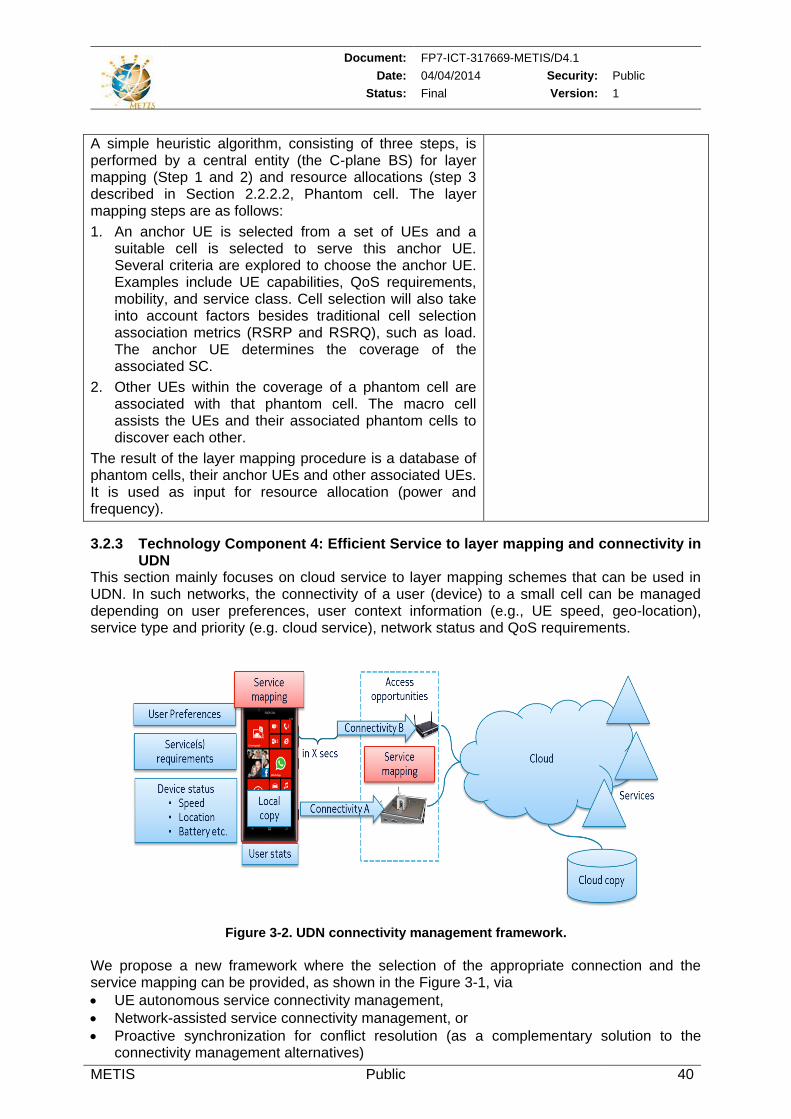
Document: FP7-ICT-317669-METIS/D4.1
Date: 04/04/2014 Security: Public
Status: Final Version: 1
METIS Public 40
A simple heuristic algorithm, consisting of three steps, is performed by a central entity (the C-plane BS) for layer mapping (Step 1 and 2) and resource allocations (step 3 described in Section 2.2.2.2, Phantom cell. The layer mapping steps are as follows:
1. An anchor UE is selected from a set of UEs and a suitable cell is selected to serve this anchor UE. Several criteria are explored to choose the anchor UE. Examples include UE capabilities, QoS requirements, mobility, and service class. Cell selection will also take into account factors besides traditional cell selection association metrics (RSRP and RSRQ), such as load. The anchor UE determines the coverage of the associated SC.
2. Other UEs within the coverage of a phantom cell are associated with that phantom cell. The macro cell assists the UEs and their associated phantom cells to discover each other.
The result of the layer mapping procedure is a database of phantom cells, their anchor UEs and other associated UEs. It is used as input for resource allocation (power and frequency).
3.2.3 Technology Component 4: Efficient Service to layer mapping and connectivity in UDN
This section mainly focuses on cloud service to layer mapping schemes that can be used in UDN. In such networks, the connectivity of a user (device) to a small cell can be managed depending on user preferences, user context information (e.g., UE speed, geo-location), service type and priority (e.g. cloud service), network status and QoS requirements.
Figure 3-2. UDN connectivity management framework.
We propose a new framework where the selection of the appropriate connection and the service mapping can be provided, as shown in the Figure 3-1, via
UE autonomous service connectivity management,
Network-assisted service connectivity management, or
Proactive synchronization for conflict resolution (as a complementary solution to the connectivity management alternatives)
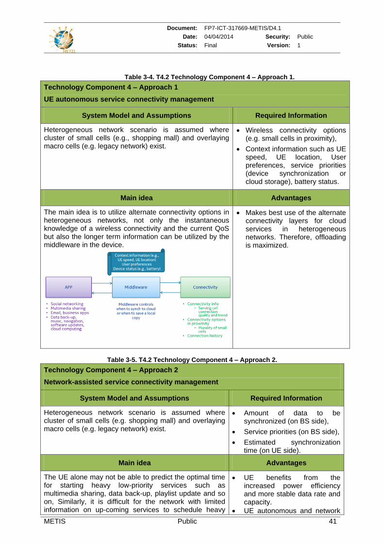
Document: FP7-ICT-317669-METIS/D4.1
Date: 04/04/2014 Security: Public
Status: Final Version: 1
METIS Public 41
Table 3-4. T4.2 Technology Component 4 – Approach 1.
Technology Component 4 – Approach 1
UE autonomous service connectivity management
System Model and Assumptions Required Information
Heterogeneous network scenario is assumed where cluster of small cells (e.g., shopping mall) and overlaying macro cells (e.g. legacy network) exist.
Wireless connectivity options (e.g. small cells in proximity),
Context information such as UE speed, UE location, User preferences, service priorities (device synchronization or cloud storage), battery status.
Main idea Advantages
The main idea is to utilize alternate connectivity options in heterogeneous networks, not only the instantaneous knowledge of a wireless connectivity and the current QoS but also the longer term information can be utilized by the middleware in the device.
Makes best use of the alternate connectivity layers for cloud services in heterogeneous networks. Therefore, offloading is maximized.
Table 3-5. T4.2 Technology Component 4 – Approach 2.
Technology Component 4 – Approach 2
Network-assisted service connectivity management
System Model and Assumptions Required Information
Heterogeneous network scenario is assumed where cluster of small cells (e.g. shopping mall) and overlaying macro cells (e.g. legacy network) exist.
Amount of data to be synchronized (on BS side),
Service priorities (on BS side),
Estimated synchronization time (on UE side).
Main idea Advantages
The UE alone may not be able to predict the optimal time for starting heavy low-priority services such as multimedia sharing, data back-up, playlist update and so on, Similarly, it is difficult for the network with limited information on up-coming services to schedule heavy
UE benefits from the increased power efficiency and more stable data rate and capacity.
UE autonomous and network
Document: FP7-ICT-317669-METIS/D4.1
Date: 04/04/2014 Security: Public
Status: Final Version: 1
METIS Public 42
low-priority services in an efficient way. Therefore, service type information, such as the amount of data to be synchronized and the service priority/urgency, needs to be provided by the UE to the network. Using the received information, the network can provide assistance to the UE, for example, by estimating the pending period. Then, the UE can decide when to synchronize with the cloud based on the network assistance information as illustrated above. For flowchart see Appendix 7.5
assisted connectivity management schemes can be implemented together.
Table 3-6. T4.2 Technology Component 4 – Approach 3.
Technology Component 4 – Approach 3
Proactive synchronization for conflict resolution
System Model and Assumptions Required Information
Heterogeneous network scenario is assumed where cluster of small cells (e.g. shopping mall) and overlaying macro cells (e.g. legacy network) exist.
Synchronization information per UE and per service (on BS side)
Main idea Advantages
To complement the connectivity management alternatives, this proactive approach solves potential synchronization conflicts that may result when changing from one layer/connection to another. Examples include editing the same document or video which can occur due to the changes in the planned synchronization time, an interruption in the broadband connectivity, temporary lack of resources or an on-going synchronization. To avoid synchronization conflicts proactively, each device can signal to the cloud server about its wireless connectivity characteristics and the re-estimated synchronization time. As a response, the cloud server can signal back an expected conflict to the devices and asks them for a re-ordering of synchronization tasks (e.g., fast fetching, or postponing). The signalling flow illustrating the proposed mechanism is shown in the appendix 7.5
Synchronization problems can be solved proactively in the cloud server applying UE assistance.
3.2.3.1 Technology Component 5: Efficient vertical RAT mapping through vertical handover
Distributed cell load balancing strategies must rely on some type of collaborative exchange of information, such as control signaling between radio access nodes. Currently, such exchange of information is usually based upon two different approaches in current state of the art radio access technologies:
A direct interface between the involved radio access nodes, such as e.g. X2 interface between eNodeBs in LTE. Such direct interface provides the fastest, easiest way to exchange cell load information for self-managed load balancing strategies.
An indirect connection between radio access nodes based on standard 3GPP RIM (RAN Information Management). Such a protocol exploits the core network nodes for the exchange of control information between different Radio Access Technologies (RATs).
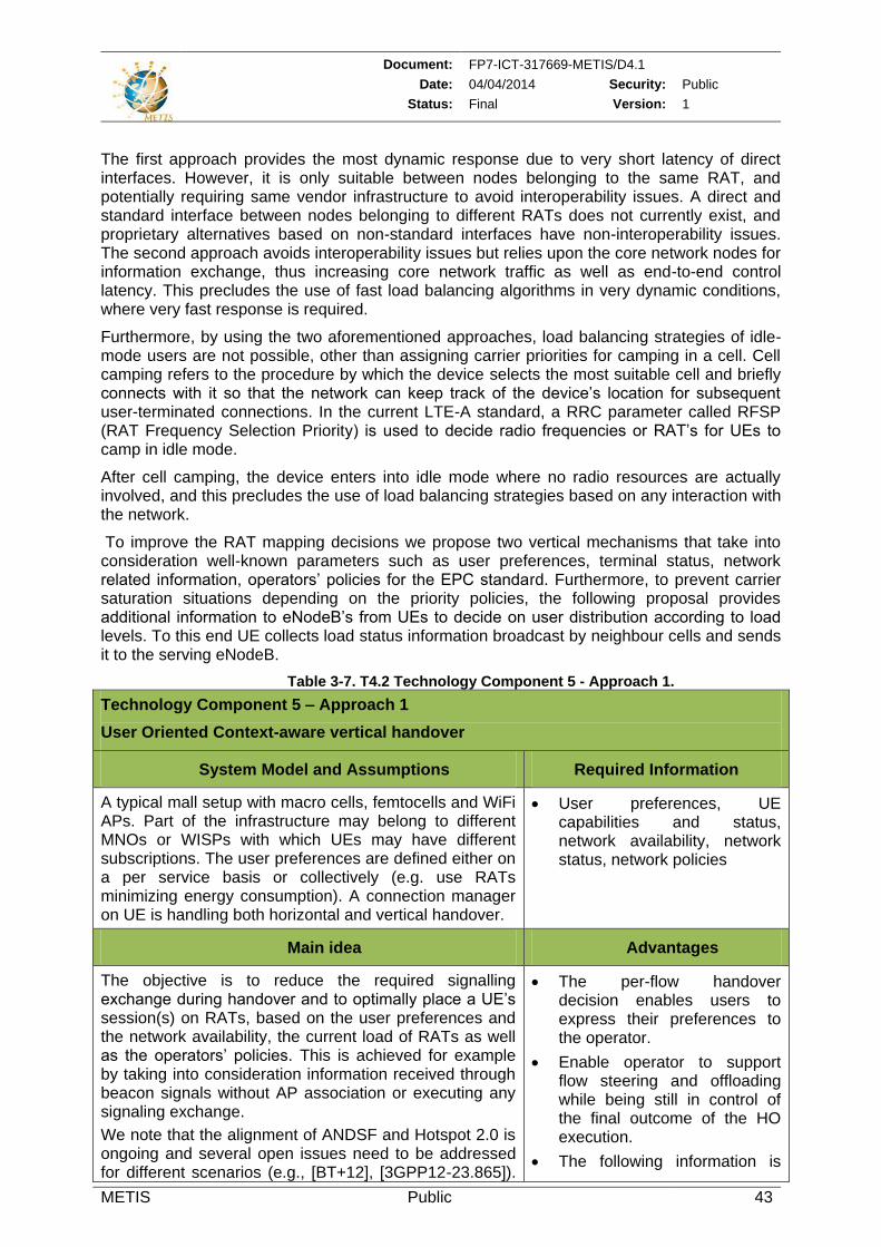
Document: FP7-ICT-317669-METIS/D4.1
Date: 04/04/2014 Security: Public
Status: Final Version: 1
METIS Public 43
The first approach provides the most dynamic response due to very short latency of direct interfaces. However, it is only suitable between nodes belonging to the same RAT, and potentially requiring same vendor infrastructure to avoid interoperability issues. A direct and standard interface between nodes belonging to different RATs does not currently exist, and proprietary alternatives based on non-standard interfaces have non-interoperability issues. The second approach avoids interoperability issues but relies upon the core network nodes for information exchange, thus increasing core network traffic as well as end-to-end control latency. This precludes the use of fast load balancing algorithms in very dynamic conditions, where very fast response is required.
Furthermore, by using the two aforementioned approaches, load balancing strategies of idle-mode users are not possible, other than assigning carrier priorities for camping in a cell. Cell camping refers to the procedure by which the device selects the most suitable cell and briefly connects with it so that the network can keep track of the device’s location for subsequent user-terminated connections. In the current LTE-A standard, a RRC parameter called RFSP (RAT Frequency Selection Priority) is used to decide radio frequencies or RAT’s for UEs to camp in idle mode.
After cell camping, the device enters into idle mode where no radio resources are actually involved, and this precludes the use of load balancing strategies based on any interaction with the network.
To improve the RAT mapping decisions we propose two vertical mechanisms that take into consideration well-known parameters such as user preferences, terminal status, network related information, operators’ policies for the EPC standard. Furthermore, to prevent carrier saturation situations depending on the priority policies, the following proposal provides additional information to eNodeB’s from UEs to decide on user distribution according to load levels. To this end UE collects load status information broadcast by neighbour cells and sends it to the serving eNodeB.
Table 3-7. T4.2 Technology Component 5 - Approach 1.
Technology Component 5 – Approach 1
User Oriented Context-aware vertical handover
System Model and Assumptions Required Information
A typical mall setup with macro cells, femtocells and WiFi APs. Part of the infrastructure may belong to different MNOs or WISPs with which UEs may have different subscriptions. The user preferences are defined either on a per service basis or collectively (e.g. use RATs minimizing energy consumption). A connection manager on UE is handling both horizontal and vertical handover.
User preferences, UE capabilities and status, network availability, network status, network policies
Main idea Advantages
The objective is to reduce the required signalling exchange during handover and to optimally place a UE’s session(s) on RATs, based on the user preferences and the network availability, the current load of RATs as well as the operators’ policies. This is achieved for example by taking into consideration information received through beacon signals without AP association or executing any signaling exchange.
We note that the alignment of ANDSF and Hotspot 2.0 is ongoing and several open issues need to be addressed for different scenarios (e.g., [BT+12], [3GPP12-23.865]).
The per-flow handover decision enables users to express their preferences to the operator.
Enable operator to support flow steering and offloading while being still in control of the final outcome of the HO execution.
The following information is
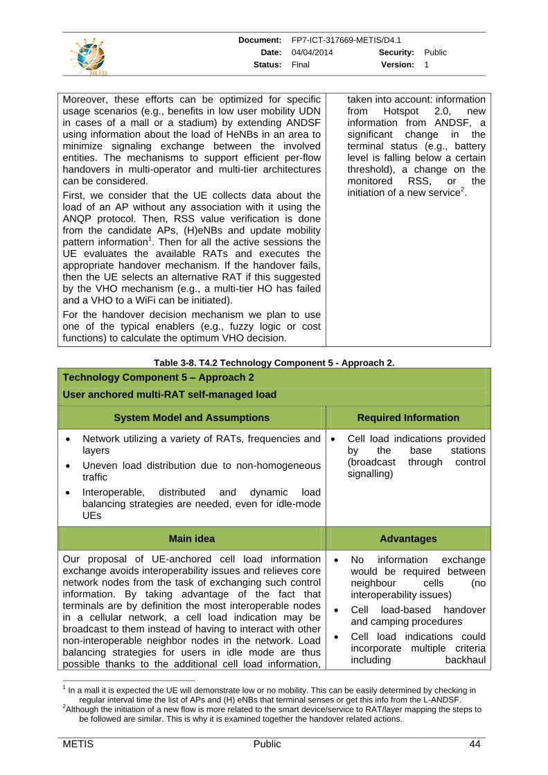
Document: FP7-ICT-317669-METIS/D4.1
Date: 04/04/2014 Security: Public
Status: Final Version: 1
METIS Public 44
Moreover, these efforts can be optimized for specific usage scenarios (e.g., benefits in low user mobility UDN in cases of a mall or a stadium) by extending ANDSF using information about the load of HeNBs in an area to minimize signaling exchange between the involved entities. The mechanisms to support efficient per-flow handovers in multi-operator and multi-tier architectures can be considered.
First, we consider that the UE collects data about the load of an AP without any association with it using the ANQP protocol. Then, RSS value verification is done from the candidate APs, (H)eNBs and update mobility pattern information1. Then for all the active sessions the UE evaluates the available RATs and executes the appropriate handover mechanism. If the handover fails, then the UE selects an alternative RAT if this suggested by the VHO mechanism (e.g., a multi-tier HO has failed and a VHO to a WiFi can be initiated).
For the handover decision mechanism we plan to use one of the typical enablers (e.g., fuzzy logic or cost functions) to calculate the optimum VHO decision.
taken into account: information from Hotspot 2.0, new information from ANDSF, a significant change in the terminal status (e.g., battery level is falling below a certain threshold), a change on the monitored RSS, or the initiation of a new service2.
Table 3-8. T4.2 Technology Component 5 - Approach 2.
Technology Component 5 – Approach 2
User anchored multi-RAT self-managed load
System Model and Assumptions Required Information
Network utilizing a variety of RATs, frequencies and layers
Uneven load distribution due to non-homogeneous traffic
Interoperable, distributed and dynamic load balancing strategies are needed, even for idle-mode UEs
Cell load indications provided by the base stations (broadcast through control signalling)
Main idea Advantages
Our proposal of UE-anchored cell load information exchange avoids interoperability issues and relieves core network nodes from the task of exchanging such control information. By taking advantage of the fact that terminals are by definition the most interoperable nodes in a cellular network, a cell load indication may be broadcast to them instead of having to interact with other non-interoperable neighbor nodes in the network. Load balancing strategies for users in idle mode are thus possible thanks to the additional cell load information,
No information exchange would be required between neighbour cells (no interoperability issues)
Cell load-based handover and camping procedures
Cell load indications could incorporate multiple criteria including backhaul
1 In a mall it is expected the UE will demonstrate low or no mobility. This can be easily determined by checking in
regular interval time the list of APs and (H) eNBs that terminal senses or get this info from the L-ANDSF. 2Although the initiation of a new flow is more related to the smart device/service to RAT/layer mapping the steps to
be followed are similar. This is why it is examined together the handover related actions.
Document: FP7-ICT-317669-METIS/D4.1
Date: 04/04/2014 Security: Public
Status: Final Version: 1
METIS Public 45
which complements signal strength-based cell selection/reselection. Handover algorithms in connected mode, where devices have proper radio resources assigned to them by the network, can also benefit from modified measurement reports sent from the terminals, by including cell load indications from neighbour cells prior to performing a handover. This proposal is therefore suitable for coexistence between different RATs, frequencies, layers and radio access nodes in a seamless way.
congestion, processing load and radio resource usage
KPIs such as the distribution of the number of users in both idle and connected modes, and the distribution of individual throughputs experienced by connected users will be investigated.
3.3 Smart mobility management
In case of user mobility, context information can be exploited to optimize handover and let the network entities select the target RAT based on, for example, estimated data rate and observed network load. Indeed, the requirements of individual users may be different, depending on the users’ mobility state, trajectory, applications; hence when available the mobility and the context information can assist the designing of more effective user-specific mobility robustness optimization. Furthermore, for trajectory predictions interfacing, signaling and feedback mechanisms are required between handsets and the network. Therefore the target is to optimize and reduce the required signaling efforts for users’ trajectory evaluation. Of particular concern are the handover optimizations of fast moving UEs, since they experience higher handover rates and potentially suffer higher failure rates than slow moving UEs.
This section presents new signaling and handover optimization schemes that exploit context to enhance the mobility management in multi-layer and multi-RAT environments.
3.3.1 State-of-the-art
The state of the art handover mechanisms used for mobility management tasks are limited mainly to short term occurrence, e.g. degradation of received radio level. However, such short term mechanisms can just provide small scale network optimizations. For an enhanced network optimization (> 2 cells), e.g. to cope with network load distribution and high data rates, better mechanisms with new input parameters are needed. In [CMV13] the authors show that using short term context information such as Channel State Information (CSI) together with long term context information (handover history) the next cell can be accurately predicted in a real time manner, long time before the standard handover procedure is executed. Furthermore, the KPIs used to evaluate the handover management and the prediction of these parameters can also be exploited as context information for handover optimization purposes [SWW08], [MCC+11].
3.3.1.1 Cell handover optimization
Self-optimization schemes that are able to adaptively adjust handover (HO) parameter settings given varying or recurring mobility scenarios are needed for robust network performance when mobile users are present. In [Alo10], a self-optimizing algorithm for HO parameter control is presented. The algorithm iteratively adjusts the parameter settings of time-to-trigger (TTT) and HO margin (HOM) depending on the oscillations experienced between different cell pairs. A first trend-based HO optimization algorithm, referred to as TBHOA, is presented in [JBT+10] where the Mobile Network Operator (MNO) defines a set of major KPIs and assigns certain weights to these KPIs with respect to the MNO’s policy. The TBHOA tries to optimize system performance by executing actions stored in a lookup table (LUT) when a certain KPI is below threshold. The distributed HO optimization procedure presented in [EB11] combines target and source cell information, such as radio link failure (RLF) indication messages, HO reports, and detected ping-pong HOs, into KPIs indicating too late or too early HOs. It assigns weights to KPIs, and determines whether the values for event
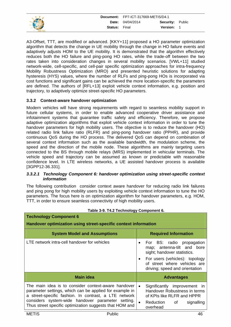
Document: FP7-ICT-317669-METIS/D4.1
Date: 04/04/2014 Security: Public
Status: Final Version: 1
METIS Public 46
A3-Offset, TTT, are modified or advanced. [KKY+11] proposed a HO parameter optimization algorithm that detects the change in UE mobility through the change in HO failure events and adaptively adjusts HOM to the UE mobility. It is demonstrated that the algorithm effectively reduces both the HO failure and ping-pong HO rates, while the trade-off between the two rates taken into consideration changes in several mobility scenarios. [VWL+11] studied network-wide, cell-specific, and cell-pair specific optimization approaches for intra-frequency Mobility Robustness Optimization (MRO) and presented heuristic solutions for adapting hysteresis (HYS) values, where the number of RLFs and ping-pong HOs is incorporated via cost functions and significant gains can be achieved the more location-specific the parameters are defined. The authors of [RFL+13] exploit vehicle context information, e.g. position and trajectory, to adaptively optimize street-specific HO parameters.
3.3.2 Context-aware handover optimization
Modern vehicles will have strong requirements with regard to seamless mobility support in future cellular systems, in order to enable advanced cooperative driver assistance and infotainment systems that guarantee traffic safety and efficiency. Therefore, we propose adaptive optimization algorithms that exploit vehicle context information in order to tune the handover parameters for high mobility users. The objective is to reduce the handover (HO) related radio link failure ratio (RLFR) and ping-pong handover ratio (PPHR), and provide continuous QoS during the HO process. The delivered QoS can depend on combination of several context information such as the available bandwidth, the modulation scheme, the speed and the direction of the mobile node. These algorithms are mainly targeting users connected to the BS through mobile relays (MRS) implemented in vehicular terminals. The vehicle speed and trajectory can be assumed as known or predictable with reasonable confidence level. In LTE wireless networks, a UE assisted handover process is available [3GPP12-36.331].
3.3.2.1 Technology Component 6: handover optimization using street-specific context information
The following contribution consider context aware handover for reducing radio link failures and ping pong for high mobility users by exploiting vehicle context information to tune the HO parameters. The focus here is on optimization algorithm for handover parameters, e.g. HOM, TTT, in order to ensure seamless connectivity of high mobility users.
Table 3-9. T4.2 Technology Component 6.
Technology Component 6
Handover optimization using street-specific context information
System Model and Assumptions Required Information
LTE network intra-cell handover for vehicles
For BS: radio propagation map; antenna-tilt and bore sight; handover statistics.
For users (vehicles): topology of street where vehicles are driving; speed and orientation
Main idea Advantages
The main idea is to consider context-aware handover parameter settings, which can be applied for example in a street-specific fashion. In contrast, a LTE network considers system-wide handover parameter setting. Thus street specific optimization suggests that HOM and
Significantly improvement in Handover Robustness in terms of KPIs like RLFR and HPPR
Reduction of signalling overhead
Document: FP7-ICT-317669-METIS/D4.1
Date: 04/04/2014 Security: Public
Status: Final Version: 1
METIS Public 47
TTT should be chosen on a street-specific basis so as to find a desired trade-off between different handover KPIs that, in general, contradict each other and therefore cannot be minimized at the same time using context information. The optimization is done using available context information, such as speed and location of vehicles. The prediction of this context information is out of scope of this work. Finally, to measure the efficiency of the proposed algorithms we are considering handover related KPIs such as RLF, HPPR.
Mechanism can easily adapted to the LTE system.
3.3.2.2 Technology component 7: Context aware mobility handover optimization using Fuzzy Q-Learning
The high mobility of user groups or moving networks introduces new challenges compared to static users and may results in degraded user experience and lower network performance. To address these challenges Fuzzy Q-Learning-based approach is developed to provide a generic basis for enabling self-optimizing and self-healing network operations. The designed concept consists of the following key components: Fuzzy Inference System (FIS), heuristic Exploration/Exploitation Policy (EEP), and Q-Learning (QL).
Table 3-10. T4.2 Technology Component 7.
Technology component 7
Context aware mobility handover optimization using Fuzzy Q-Learning
System Model and Assumptions Required Information
LTE macro cell system with a mixture of static users and mobile users connected to it. Information exchange via X2 interface for cell-pair specific adaptations.
MNO policy (KPI targets)
HO parameter (HYS, TTT, CIO) settings and range
KPI updates (connection dropping ratio, HO failure ratio, ping-pong HO ratio) for determining system state
Main idea Advantages
Fuzzy Q-Learning (FQL) based scheme applies a limited EEP and first classifies the universe of discourse using a sufficiently large but limited number of fuzzy sets. System states which are based on monitored KPIs and received reinforcement signal are determined during operation using fuzzy labels resulting from a set of predefined rules describing each considered situation. A limited rule set can be carefully designed that reflects the situations the system may be exposed in operation. Further, the FIS assesses system conditions based on these classification results and decides upon which adaptations or counteractions to trigger by following its EEP, thus learning to optimize system performance given varying system states. This scheme enables each node (e.g. BS) to learn the effectiveness of applied actions and to perform optimal HO parameter adaptations according to locally observed conditions, thus establishing context-awareness
Knowledge for designing FIS rules can be intuitively specified
Autonomously adapts HO parameters to local, cell sector-specific conditions and setting HO parameters in a cell pair-specific manner, while simultaneously accounting for several KPIs
Less complexity compared to complex machine learning techniques (based on artificial neural network)
Document: FP7-ICT-317669-METIS/D4.1
Date: 04/04/2014 Security: Public
Status: Final Version: 1
METIS Public 48
(description and results in Appendix 7.6)
3.3.2.3 Technology Component 8: D2D handover schemes for mobility management
D2D provides low power and high data rate communications between end-users in addition to the low latency compared to the cellular services in which the core network has to be involved. However, providing low latency reliable communication becomes challenging in case of mobility. For instance, a cell-edge DUE may often be triggered to handover to another eNB, and then it may not be easy to maintain the ongoing delay-sensitive D2D services if more than one eNB is involved in D2D control unless the eNBs have ideal backhaul connection. The rest of this section proposes two complementary smart mobility solutions for D2D.
Table 3-11. T4.2 Technology Component 8 – Approach 1.
Technology Component 8 – Approach 1
D2D-aware handover management
System Model and Assumptions Required Information
D2D users (DUEs) have ongoing delay sensitive D2D application. D2D control is partially at the network e.g., for band allocation, state and mobility control. DUEs are controlled under the same base station initially and at least one of the DUEs is mobile.
Latency, RSSI (RSRP) / RSQI (RSRQ), QoS indicators (for both cellular and D2D)
Main idea Advantages
The main idea is to define a new D2D handover condition (signal strength/quality threshold) in addition to the traditional cellular handover condition. In fact, considering two BSs (BS1 and BS2) and two UEs (UE1 and UE2) both are initially controlled by BS1. When UE1 moves towards BS2 coverage and fulfils the cellular handover condition; the network postpones its handover to BS2 until the signal predefined D2D handover condition is fulfilled. Additionally, the handover of UE2 to BS2 is advanced when D2D handover is fulfilled by UE2.
Reduces signalling overhead due to information exchange between two base stations) and improves D2D performance in terms of control latency.
Table 3-12. T4.2 Technology Component 8 – Approach 2.
Technology Component 8 – Approach 2
D2D-triggered handover
System Model and Assumptions Required Information
DUEs with ongoing delay sensitive D2D application. One DUE joining the pair or the cluster of DUEs. D2D control is partially done by the network e.g. for band allocation, state and mobility control.
Backhaul latency, RSSI (RSRP) / RSQI (RSRQ), QoS indicators (for both cellular and D2D)
Main idea Advantages
Keeping a pair of DUEs under different BS may cause additional delay due to information exchange between controlling BSs. To provide better user experience (in terms of latency) and less control overhead in D2D group communications, DUEs should be clustered in a
Reduces signalling overhead
improved D2D performance in terms of control latency
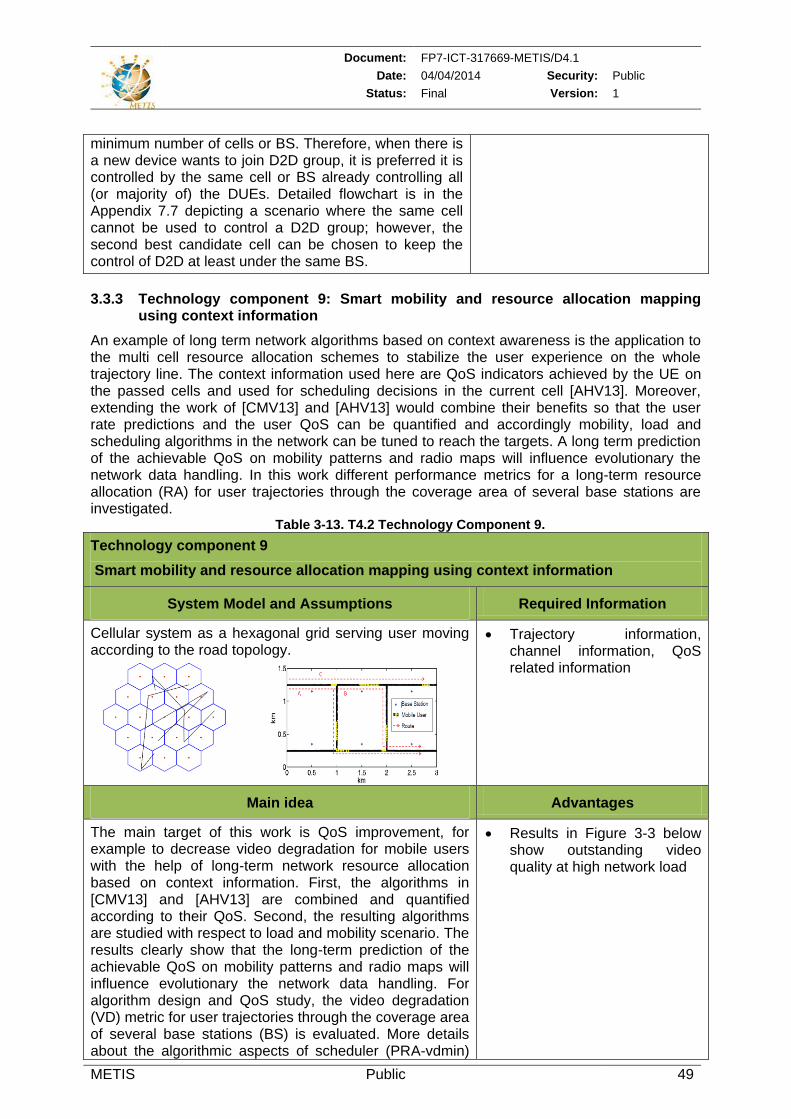
Document: FP7-ICT-317669-METIS/D4.1
Date: 04/04/2014 Security: Public
Status: Final Version: 1
METIS Public 49
minimum number of cells or BS. Therefore, when there is a new device wants to join D2D group, it is preferred it is controlled by the same cell or BS already controlling all (or majority of) the DUEs. Detailed flowchart is in the Appendix 7.7 depicting a scenario where the same cell cannot be used to control a D2D group; however, the second best candidate cell can be chosen to keep the control of D2D at least under the same BS.
3.3.3 Technology component 9: Smart mobility and resource allocation mapping using context information
An example of long term network algorithms based on context awareness is the application to the multi cell resource allocation schemes to stabilize the user experience on the whole trajectory line. The context information used here are QoS indicators achieved by the UE on the passed cells and used for scheduling decisions in the current cell [AHV13]. Moreover, extending the work of [CMV13] and [AHV13] would combine their benefits so that the user rate predictions and the user QoS can be quantified and accordingly mobility, load and scheduling algorithms in the network can be tuned to reach the targets. A long term prediction of the achievable QoS on mobility patterns and radio maps will influence evolutionary the network data handling. In this work different performance metrics for a long-term resource allocation (RA) for user trajectories through the coverage area of several base stations are investigated.
Table 3-13. T4.2 Technology Component 9.
Technology component 9
Smart mobility and resource allocation mapping using context information
System Model and Assumptions Required Information
Cellular system as a hexagonal grid serving user moving according to the road topology.
Trajectory information, channel information, QoS related information
Main idea Advantages
The main target of this work is QoS improvement, for example to decrease video degradation for mobile users with the help of long-term network resource allocation based on context information. First, the algorithms in [CMV13] and [AHV13] are combined and quantified according to their QoS. Second, the resulting algorithms are studied with respect to load and mobility scenario. The results clearly show that the long-term prediction of the achievable QoS on mobility patterns and radio maps will influence evolutionary the network data handling. For algorithm design and QoS study, the video degradation (VD) metric for user trajectories through the coverage area of several base stations (BS) is evaluated. More details about the algorithmic aspects of scheduler (PRA-vdmin)
Results in Figure 3-3 below show outstanding video quality at high network load
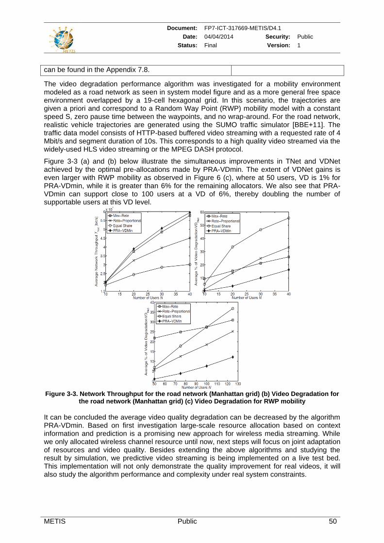
Document: FP7-ICT-317669-METIS/D4.1
Date: 04/04/2014 Security: Public
Status: Final Version: 1
METIS Public 50
can be found in the Appendix 7.8.
The video degradation performance algorithm was investigated for a mobility environment modeled as a road network as seen in system model figure and as a more general free space environment overlapped by a 19-cell hexagonal grid. In this scenario, the trajectories are given a priori and correspond to a Random Way Point (RWP) mobility model with a constant speed S, zero pause time between the waypoints, and no wrap-around. For the road network, realistic vehicle trajectories are generated using the SUMO traffic simulator [BBE+11]. The traffic data model consists of HTTP-based buffered video streaming with a requested rate of 4 Mbit/s and segment duration of 10s. This corresponds to a high quality video streamed via the widely-used HLS video streaming or the MPEG DASH protocol.
Figure 3-3 (a) and (b) below illustrate the simultaneous improvements in TNet and VDNet achieved by the optimal pre-allocations made by PRA-VDmin. The extent of VDNet gains is even larger with RWP mobility as observed in Figure 6 (c), where at 50 users, VD is 1% for PRA-VDmin, while it is greater than 6% for the remaining allocators. We also see that PRA-VDmin can support close to 100 users at a VD of 6%, thereby doubling the number of supportable users at this VD level.
Figure 3-3. Network Throughput for the road network (Manhattan grid) (b) Video Degradation for
the road network (Manhattan grid) (c) Video Degradation for RWP mobility
It can be concluded the average video quality degradation can be decreased by the algorithm PRA-VDmin. Based on first investigation large-scale resource allocation based on context information and prediction is a promising new approach for wireless media streaming. While we only allocated wireless channel resource until now, next steps will focus on joint adaptation of resources and video quality. Besides extending the above algorithms and studying the result by simulation, we predictive video streaming is being implemented on a live test bed. This implementation will not only demonstrate the quality improvement for real videos, it will also study the algorithm performance and complexity under real system constraints.
Document: FP7-ICT-317669-METIS/D4.1
Date: 04/04/2014 Security: Public
Status: Final Version: 1
METIS Public 51
3.3.4 Technology component 10: Signaling for trajectory prediction
The availability of robust user movement predictions is of high importance for optimizing RAT selection, mobility support, and smart mapping of user service onto available RAT layers. In this research work we consider corresponding signalling for trajectory prediction in Section 3.1.4 employed to deduce the user’s next cell.
Table 3-14. T4.2 Technology Component 10.
Technology component 10
Signaling for trajectory prediction
System Model and Assumptions Required Information
The trajectory prediction scheme relies on updates of the user terminal’s context information that are recorded by the BS at fixed but velocity-dependent intervals, and where either the terminal actively provides speed and location information or the BS and its neighbours have to cooperatively determine the terminal location using e.g. trilateration.
Speed and location information updates
Main idea Advantages
To deduce the user’s next cell using trajectory prediction mechanism the BS prepares a list of potential next cells for user transition based on predicted user trajectories. A notification about the arrival of user(s) (context message) is sent well in advance from the serving BS to the neighbouring cell next target to prepare the user transition.
Enables triggering suitable RRM algorithms pro-actively at the potential target cell.
Facilitate interference prediction by sending notifications on cell transitions to other potential target cells (set of predicted next cells).
Document: FP7-ICT-317669-METIS/D4.1
Date: 04/04/2014 Security: Public
Status: Final Version: 1
METIS Public 52
4 Functional Network Enablers
T4.3 deals with the functional network enablers needed for the interference and mobility management solutions proposed in T4.1 and T4.2 and presented in chapter 2 and chapter 3 above, respectively. This task is split into two main activities:
New management interfaces, which aims at providing all the required interfaces for the efficient information fusion and management of the network. This includes interface to facilitate the exchange of information between operators as well as the cooperation between the operators and the external services providers to enable better planning and performances.
Auto-integration and Self-management, where the focus is on the dynamic evolution of the network and its capability to integrate new nodes. More precisely, partners are investigating solutions for automatic integration of new nodes that may be required to meet the capacity increase and the dynamic configuration of the network according to its needs.
At this stage, the work in first topic was mainly focusing on analyzing the METIS needs to identify the new interface to be developed. For the second topic, some partners started investigating auto-integration and dynamic configuration aspects via the integration of new nomadic cells into the network architecture, the activation or de-activation of access nodes for energy saving and also the use of clustering schemes for coordination between network entities in order to optimize the network operations.
4.1 New management interfaces
For the new management interfaces topic inter-operator communication and collaboration in terms of network management and context information exchange are considered. The identification of the new management interfaces is based on the analysis of the SOTA (i.e., standardization bodies, research projects and initiatives) to identify the needs of the T4.1 and T4.2 mechanisms. Partners intend to develop schemes for integration of heterogeneous network deployments, into a mobile broadband operators’ infrastructure; focus will be put on the resilient integration of new network nodes.
4.1.1 State of the art analysis for METIS needs
This section provides an overview of working items related to management interfaces within standardization, initiatives and research projects. This state of the art analysis will help proposing modification to existing works or designing new interfaces to meet the needs of WP4 work on interference identification, smart and coordinated resource usage, smart device/service to RAT/layer mapping, smart signaling for mobility, auto-integration and self-management of nodes and cluster formation. The scope of WP4 work includes interactions between:
Services providers and network operators,
Base stations/ Networks nodes and User Equipments,
Network operators operating within same area.
Table 4-1 summarizes of a set of initiatives that have been specifying management interfaces; such interfaces are in the scope of METIS Management Interfaces work and will be a basis for the way forward.
Document: FP7-ICT-317669-METIS/D4.1
Date: 04/04/2014 Security: Public
Status: Final Version: 1
METIS Public 53
Table 4-1. Summary of Initiatives that have been specifying management interfaces.
Initiative/ Project
Description Interfaces of interest of METIS
3GPP IRP
(The Integration Reference Point)
IRP is a 3GPP standard for Fault and Configuration Management specified in the Series 28 [3GPP11-28.734] and Series 32 [3GPP11-32.591] [3GPP11-32.103] of 3GPP Technical Specifications.
Interface IRP
Generic / Common Interface IRPs: Fault Management related Interface IRPs (e.g. Alarm and Test Management)
Configuration Management Interface IRPs (e.g. automatic configuration of eNBs and software management)
Performance Management Interface IRP: Performance and Trace Management
Special Purpose related Interface IRPs (e.g. Notification Log IRP, File Transfer IRP, Communication Surveillance)
NRM (Network Resource Model) IRP
Generic NRM IRP: Access Network (UTRAN, E-UTRAN, GERAN, Generic RAN)
Core/IMS NRM IRPs (e.g. Core, IMS, EPC)
H(e)NB related NRM IRPs (e.g. Home eNB)
Service Management NRM IRPs (e.g. subscription management, user data repository)
Special-purpose NRM IRPs (e.g. SON policy, Transport Network, Signaling Transport)
FI-WARE
(Future Internet Core Platform)
[FIW12-D731b]
FI-WARE develops open specifications for delivering a novel service infrastructure, building upon Generic Enablers which offer reusable and commonly shared functions making it easier to develop Future Internet Applications in multiple sectors.
Interface to Device and Network (I2ND) management interfaces
Connected Device Interfacing (CDI): exploit the device capabilities, user profiles;
Network Information & Control (NetIC): It exposes network status information and enables some programmability within the network.
Service, Capability, Connectivity and Control (S3C): S3C aims at providing a unified and scalable control of the connectivity of the devices over heterogeneous access networks and core network technologies, transparent to the devices and to the services deployed on top.
CE (Cloud Edge) towards the Cloud Proxies. Cloud Proxies are FI-WARE specified gateways, which connect and control a set-up of nodes towards the Internet or/and an operator network.
TMF
(TeleManagement Forum)
TM is a global, non-profit industry association focused on simplifying the complexity of running a service provider’s business through a wealth of knowledge, intellectual capital, collaboration and standards. TM Forum’s scope incorporates service and network management.
Shared Information/Data Model (SID) is a unified reference data model providing a single set of terms for business objects in telecommunications
Enhanced Telecom Operations Map (eTOM) [TMF12-GB921-CP-12.5] is designed to define the most widely used and accepted standard for business processes in the telecommunications
Document: FP7-ICT-317669-METIS/D4.1
Date: 04/04/2014 Security: Public
Status: Final Version: 1
METIS Public 54
industry.
Telecom Application Map (TAM) [TMF12-GB929-13] considers the role and the functionality of the various applications that deliver OSS and BSS capability.
Integration Framework defines how the processes and information behind the applications and infrastructure can be automated by defining standardized Service Oriented Architecture (SOA)-based interfaces called Business Services.
Generic Autonomic Network Architecture (GANA) Reference Model
ETSI AFI GANA Reference Model ([Cha08] [Cha09]) prescribes design and operational principles of “autonomic decision-making manager components/elements” responsible for performing “autonomic” and “cognitive” management and control of resources.
Network Governance interface enables the operator to adjust the features of the demanded service/infrastructure in a high level language to be translated to policies defining the valid operating region for the autonomic functionality
FP7 UniverSelf Project
UniverSelf project aims at designing the Unified Management Framework (UMF) which targets at embedding the autonomic paradigms in any type of network in a consistent manner.
Interfaces i1, i2, and i3 (UMF core - NEMs) enable NEM management,
Interfaces i4, i5 and i6 among the UMF core blocks, GOV, COORD and KNOW,
Interface i7(H2N): a tool for inserting business objectives (e.g. related to new application, sets of user classes etc.), which will be translated into technology-specific terms to govern the underlying network infrastructure.
The presented initiatives, activities and specifications on new management interfaces within standardization and research sejctor are initially assessed as relevant to METIS WP4 work on management interfaces and could be utilized in a complimentary way. Figure 4-1 proposes a mapping between management interfaces activities and WP4 information flows accordingly.
The next steps to be conducted in T4.3 are as follows:
Further deep study on few selected initiatives,
Investigate and identify respective activities for inter-operator interfacing,
Elaborate and break down operations, functionalities, management procedures and information flows from METIS WP4 point of view,
Meet some of the identified relevant activities.
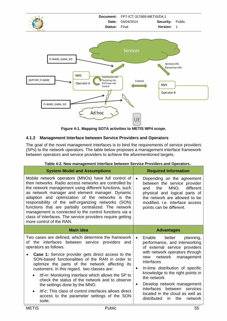
Document: FP7-ICT-317669-METIS/D4.1
Date: 04/04/2014 Security: Public
Status: Final Version: 1
METIS Public 55
Services
Operator A
NMS
Operator B
NMS
Services info Resources Info
Context
Interference infoClustering infoRAT/layer infoContext
FI-WARE, GANA, SID
3GPP IRP, FI-WARE
FI-WARE, GANA, SID
Ad hoc
UE
Figure 4-1. Mapping SOTA activities to METIS WP4 scope.
4.1.2 Management Interface between Service Providers and Operators
The goal of the novel management interfaces is to bind the requirements of service providers (SPs) to the network operators. The table below proposes a management interface framework between operators and service providers to achieve the aforementioned targets.
Table 4-2. New management interface between Service Providers and Operators.
System Model and Assumptions Required Information
Mobile network operators (MNOs) have full control of their networks. Radio access networks are controlled by the network management using different functions, such as network manager and element manager. Dynamic adaption and optimization of the networks is the responsibility of the self-organizing networks (SON) functions that are partially centralized. The network management is connected to the control functions via a class of interfaces. The service providers require getting more control of the RAN.
Depending on the agreement between the service provider and the MNO, different physical and logical parts of the network are allowed to be modified, i.e. interface access points can be different.
Main idea Advantages
Two cases are defined, which determine the framework of the interfaces between service providers and operators as follows.
Case 1: Service provider gets direct access to the SON-based functionalities of the RAN in order to optimize the parts of the network affecting its customers. In this regard, two classes are:
Itf-m: Monitoring interface which allows the SP to check the status of the network and to observe the settings done by the MNO.
Itf-c: This class of control interfaces allows direct access to the parameter settings of the SON suite.
Enable better planning, performance, and interworking of external service providers with network operators through new network management interfaces
In-time distribution of specific knowledge to the right points in the network
Develop network management interfaces between services located in the cloud as well as distributed in the network
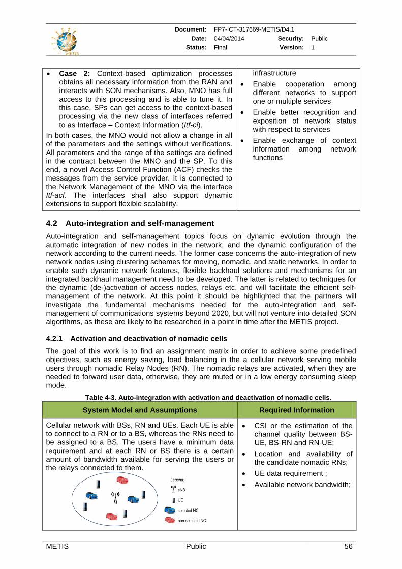
Document: FP7-ICT-317669-METIS/D4.1
Date: 04/04/2014 Security: Public
Status: Final Version: 1
METIS Public 56
Case 2: Context-based optimization processes obtains all necessary information from the RAN and interacts with SON mechanisms. Also, MNO has full access to this processing and is able to tune it. In this case, SPs can get access to the context-based processing via the new class of interfaces referred to as Interface – Context Information (Itf-ci).
In both cases, the MNO would not allow a change in all of the parameters and the settings without verifications. All parameters and the range of the settings are defined in the contract between the MNO and the SP. To this end, a novel Access Control Function (ACF) checks the messages from the service provider. It is connected to the Network Management of the MNO via the interface Itf-acf. The interfaces shall also support dynamic extensions to support flexible scalability.
infrastructure
Enable cooperation among different networks to support one or multiple services
Enable better recognition and exposition of network status with respect to services
Enable exchange of context information among network functions
4.2 Auto-integration and self-management
Auto-integration and self-management topics focus on dynamic evolution through the automatic integration of new nodes in the network, and the dynamic configuration of the network according to the current needs. The former case concerns the auto-integration of new network nodes using clustering schemes for moving, nomadic, and static networks. In order to enable such dynamic network features, flexible backhaul solutions and mechanisms for an integrated backhaul management need to be developed. The latter is related to techniques for the dynamic (de-)activation of access nodes, relays etc. and will facilitate the efficient self-management of the network. At this point it should be highlighted that the partners will investigate the fundamental mechanisms needed for the auto-integration and self-management of communications systems beyond 2020, but will not venture into detailed SON algorithms, as these are likely to be researched in a point in time after the METIS project.
4.2.1 Activation and deactivation of nomadic cells
The goal of this work is to find an assignment matrix in order to achieve some predefined objectives, such as energy saving, load balancing in the a cellular network serving mobile users through nomadic Relay Nodes (RN). The nomadic relays are activated, when they are needed to forward user data, otherwise, they are muted or in a low energy consuming sleep mode.
Table 4-3. Auto-integration with activation and deactivation of nomadic cells.
System Model and Assumptions Required Information
Cellular network with BSs, RN and UEs. Each UE is able to connect to a RN or to a BS, whereas the RNs need to be assigned to a BS. The users have a minimum data requirement and at each RN or BS there is a certain amount of bandwidth available for serving the users or the relays connected to them.
CSI or the estimation of the channel quality between BS-UE, BS-RN and RN-UE;
Location and availability of the candidate nomadic RNs;
UE data requirement ;
Available network bandwidth;
Document: FP7-ICT-317669-METIS/D4.1
Date: 04/04/2014 Security: Public
Status: Final Version: 1
METIS Public 57
Main idea Advantages
The main idea is to model the decision of activation and deactivation as an optimization problem where the objective could be energy consumption of the whole network, user battery life or network load, etc. The constraints of the optimizing problem lie in two aspects:
1. UEs and RNs must be connected to the network
2. The available bandwidth at each node must be sufficient to support the minimum rate requirement of the UEs and the forward data rate of the RNs.
Certain relaxation techniques are needed to efficiently solve the optimization problem since both objectives and constraints are non-convex.
Capacity and coverage enhancement
Network energy saving and longer UE battery life.
Load balancing
4.2.2 Clustering mechanisms
The constant growth in (mobile) devices has increased the need for coordination in order to facilitate the network management. In particular, mechanisms for grouping nodes and organizing them into clusters (groups) are required to achieve better coordination. More precisely, the clustering procedure introduces some generic advantages, for example the identification of the similarities among observations, the minimization of the communication cost, the extraction of hierarchies and specific roles, etc. Depending on the objective of the clustering procedures, nodes belonging to the same cluster may have the same or different roles.
The examination of a variety of clustering algorithms from different scientific fields and per case selection of the most suitable ones will allow us to capture the most important objectives of the application field (e.g., minimization of energy/power consumption, reliability, etc.) and see how these clustering mechanisms could be exploited to facilitate efficient mapping or to reconfigure the network to better support users mobility.
One potential generic classification of clustering schemes identifies three categories:
1) Data mining clustering schemes; these algorithms have as main target the grouping of data objects into groups with similar objects; the grouping results in the extraction of useful observations. Representative algorithms of this category are:
K-Means is a partitioning method that partitions n objects into k partitions (k ≤ n). Each partition represents a cluster and the clusters are formed in such a way to optimize a similarity function (e.g. distance). More specifically, k-Means algorithm takes as input the parameter k and partitions a set of n objects into k clusters having as objective high intra-cluster similarity and at the same time low inter-cluster similarity [HKP11].
Hierarchical Agglomerative Clustering (HAC) grouping objects into a tree of clusters with different levels of hierarchy. The tree is created either as a top-down (divisive) approach or as a bottom-up (agglomerative) [HKP11].
2) Sensor ad hoc networks: these algorithms are mainly used for minimizing the communication cost, for information fusion, and the identification of specific roles in the cluster. Usually the exploitation of local information is used and thus no global knowledge is required for the clustering of nodes. A well-known algorithm of this category is the 3 hops Between Adjacent Cluster-heads (3hBAC) algorithm that focuses on grouping nodes into small groups of radius up to 2 hops, while limiting the number of clusters produced and keeping the network structure as stable as possible. Throughout the maintenance phase excessive formation of small clusters is avoided [YC03].
Document: FP7-ICT-317669-METIS/D4.1
Date: 04/04/2014 Security: Public
Status: Final Version: 1
METIS Public 58
3) Graph theory-based schemes; in these algorithms the similarities among the observations are weighted links and the entire set of observations can be modeled as a weighted directed graph. Such schemes are in general used in biomedicine; attributes from graph theory are used in order to group entities based on the aforementioned weighted links. An example of such algorithm is Markov Clustering which partitions a graph by simulating multiple random walks inside the a graph. Thus strongly connected nodes are visited more often than nodes connected with weak paths [Don00].
Generally for grouping network nodes the sensor ad-hoc techniques are used. However, assuming that the network nodes could be viewed as simple vectors, the other two techniques (i.e., data mining and graph theory-based schemes) would also be suitable for the task.
4.2.3 Clustering toolbox
The following subsection introduces a clustering toolbox to provide the means for node clustering and helps identifying the suitable algorithms to be used for each problem (e.g., with moving nodes, static ones, energy limited ones, etc.). This toolbox is defined based on the evaluation of some indicative algorithms of each clustering category (described above).
Table 4-4. Summary of the clustering toolbox.
System Model and Assumptions Required Information
Ultra dense environment of (moving and static) nodes. Each node monitors its environment. Positioning (absolute or relative) information shall be available. Information exchange among nodes to be clustered.
Global or local context information depending on the approach and the objectives of the clustering.
Main idea Advantages
Depending on the problem and the objective, the appropriate clustering mechanism from the toolbox will be used to group the nodes. The toolbox will incorporate clustering mechanisms from several research fields (i.e., data mining, sensor – ad hoc networks, graph theory, etc.)
Put focus on objectives of each case (e.g., minimization of energy/power consumption, reliability, mobility, time to build clusters, etc.) and use most suitable mechanism, inputs, etc.
Enables incorporating centralized and decentralized schemes depending on the problem to be solved.
An experimental evaluation of clustering schemes can be found in the Appendix section 7.9.
4.2.4 Self-management enabled by central database for energy savings in the Phantom Cell Concept (PCC)
One variant of the Phantom cell architecture is called the Detached Cell Concept (DCC) which adds the capability of putting U-plane small cells in SLEEP mode or to turn them OFF in order to save energy when they do not serve many users i.e. the traffic load is low. Furthermore, the DCC architecture adds a database connected to the C-plane BS which contains some data that is not available when the U-plane BSs are inactive, such as information about the quality of the small cell channels, or information about the traffic load in the area of the small cell.
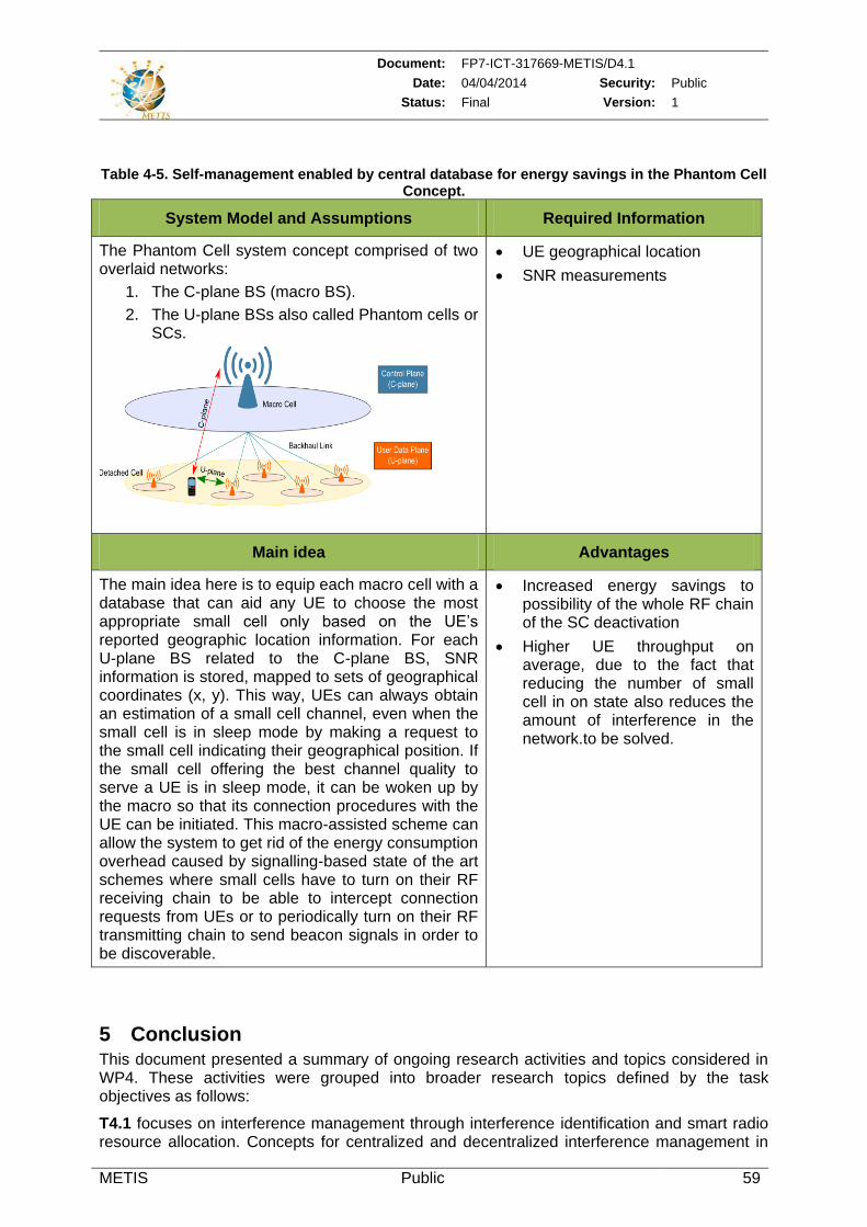
Document: FP7-ICT-317669-METIS/D4.1
Date: 04/04/2014 Security: Public
Status: Final Version: 1
METIS Public 59
Table 4-5. Self-management enabled by central database for energy savings in the Phantom Cell
Concept.
System Model and Assumptions Required Information
The Phantom Cell system concept comprised of two overlaid networks:
1. The C-plane BS (macro BS).
2. The U-plane BSs also called Phantom cells or SCs.
UE geographical location
SNR measurements
Main idea Advantages
The main idea here is to equip each macro cell with a database that can aid any UE to choose the most appropriate small cell only based on the UE’s reported geographic location information. For each U-plane BS related to the C-plane BS, SNR information is stored, mapped to sets of geographical coordinates (x, y). This way, UEs can always obtain an estimation of a small cell channel, even when the small cell is in sleep mode by making a request to the small cell indicating their geographical position. If the small cell offering the best channel quality to serve a UE is in sleep mode, it can be woken up by the macro so that its connection procedures with the UE can be initiated. This macro-assisted scheme can allow the system to get rid of the energy consumption overhead caused by signalling-based state of the art schemes where small cells have to turn on their RF receiving chain to be able to intercept connection requests from UEs or to periodically turn on their RF transmitting chain to send beacon signals in order to be discoverable.
Increased energy savings to possibility of the whole RF chain of the SC deactivation
Higher UE throughput on average, due to the fact that reducing the number of small cell in on state also reduces the amount of interference in the network.to be solved.
5 Conclusion This document presented a summary of ongoing research activities and topics considered in WP4. These activities were grouped into broader research topics defined by the task objectives as follows:
T4.1 focuses on interference management through interference identification and smart radio resource allocation. Concepts for centralized and decentralized interference management in
Document: FP7-ICT-317669-METIS/D4.1
Date: 04/04/2014 Security: Public
Status: Final Version: 1
METIS Public 60
ultra-dense networks, as well as device to device communication aspects and moving networks were covered in this task. Initial results of some of the proposed approaches were shown. The variety of the proposed solutions is expected to enable covering a broad scope of scenarios and use cases.
T4.2 deals with traffic and mobility management research activities which mainly focus on extraction, exchange and utilization of context information, as well as possible techniques for smart layer mapping and resource allocation. However, more refinement of those schemes as well as a more rigorous study will be needed in future works. The outcome of this task can add novel solutions to the METIS project by considering promising schemes that can exploit context awareness for traffic and mobility management. Some relevant context parameters from T4.2 can also be used to advance the research of T4.1, interference management.
T4.3 topics are at an early stage, and aim at providing interface enablers for network solutions proposed in WP4 as well as linking them to the architectural study in METIS. In this regard, a summary of state of the art on management interfaces was presented in the document. The document also outlined two frameworks for discussing future enablers on auto-integration and self-management. More details and investigations are further expected on this topic during the course of the project.
Within the above three tasks, research topics were grouped into technology components for better dissemination of research activities. Novel concepts within each technology component were presented using highlights with main ideas described at a high level. First results on few topics were also presented in the main section of the document. The appendix of the document presented detailed aspects of concepts through algorithm pseudo-codes, flowcharts and some additional results.
Document: FP7-ICT-317669-METIS/D4.1
Date: 04/04/2014 Security: Public
Status: Final Version: 1
METIS Public 61
6 References
[3GPP11-28.734] 3GPP TS 28 series, Signaling protocols ("stage 3") -(RSS-CN) and OAM&P and Charging [3GPP11-32.103] 3GPP TS 32.103 V11.2.0 [3GPP11-32.591] 3GPP TS 32 series, OAM&P and Charging [3GPP11-36.300] 3GPP TS 36.300 v 10.7.0, E-UTRA, Overall Description, Stage 2, Release 10 [3GPP12-23.234] 3GPP TS 23.234, V11.0.0, 3GPP system to wireless local area network (WLAN) interworking; system description (release 11), 09-2012 [3GPP12-23.865] 3GPP TR 23.865 - WLAN-NS WLAN network selection for 3GPP terminals [3GPP12-36.331] 3GPP TSG RAN, “E-UTRA Radio Resource Control (RRC) (Release 11)”, Protocol Specification 36.331 V11.1.0, September 2012. [3GPP13-0566] Ericsson, “Physical Layer Aspects of Dual Connectivity”, St. Julian’s, Malta, Feb. 2013, 3GPP Standard Contribution (R1-130566). [3GPP13-23.401] 3GPP TS 23.401, V12.1.0, GPRS enhancements for E-UTRAN access, Release 12, June 2013 [3GPP13-23.402] 3GPP TS 23.402, Architecture enhancements for non-3GPP accesses, Release 12, June 2013 [3GPP13-23.859] 3GPP TR 23.859, Local IP access (LIPA) mobility and Selected IP Traffic Offload (SIPTO) at the local network, Release 12, 04-2013 [3GPP13-24.312] 3GPP TS 24.312, Access Network Discovery and Selection Function (ANDSF) Management Objects (MO), release 12, June 2013 [3GPP13-36.300] 3GPP TS 36.300, Evolved Universal Terrestrial Radio Access (E-UTRA) and Evolved Universal Terrestrial Radio Access Netwokr (E-UTRAN) – Overall Description, Stage 2, Release 11, 3-2013 [3GPP13-36211] 3GPP TS 36.211 “Physical Channels and Modulation (Release 11)”, June 2013 [3GPPcarrier] http://www.3gpp.org/Carrier-Aggregation-explained [ABB+06] N. Agoulmine, S. Balasubramaniam, D. Botvitch, J. Strassner, E. Lehtihet and W. Donelly, "Challenges for Autonomic Network Management," in 1st conference on Modelling Autonomic Communication Environment, 2006. [AHV13] H. Abou-zeid, H. Hassanein, and S. Valentin, “Lookback scheduling for long-term quality-of-service over multiple cells”, in Proc. QoS and QoE in Wireless Commun./Networks Workshop, IWCMC, July 2013 [AKG11] A. Attar, V. Krishnamurthy, O.N. Gharehshiran, “Interference management using cognitive base-stations for UMTS LTE,” IEEE Communications Magazine, vol. 49, no. 8, pp. 152-159, Aug. 2011 [Alo10] J. Alonso-Rubio, “Self-optimization for handover oscillation control in LTE,” in IEEE Network Operations and Management Symposium (NOMS), April 2010, pp. 950–953. [APG+10] Avneesh Agrawal, Naga Bhushan, Alexei Gorokhov, Gavin B. Horn, Tingfang JI, Aamod Khandekar, Ashwin Sampath, Backhaul signaling for interference avoidance, Patent application, US 20090197588 A1, 2010 [ASQ+13] J. Andrews, S. Singh, Q. Ye, X. Lin and H. Dhillon, “An Overview of Load Balancing in HetNets: Old Myths and Open Problems”, arXiv preprint arXiv:1307.7779, 2013 [BBE+11] M. Behrisch, L. Bieker, J. Erdmann, and D. Krajzewicz, “SUMO -Simulation of Urban MObility: An Overview,” in Proc. Third Int. Conf. on Advances in System Simulation (SIMUL 2011), pp. 63–68, Oct. 2011. [BCG11] P. Bellavista, A. Corradi and C. Giannelli, "A Unifying Perspective on Context-Aware Evaluation and Management of Heterogeneous Wireless Connectivity," IEEE Communication Surveys Tutorials, vol. 13, no. 3, pp. 337-357, 2011.
Document: FP7-ICT-317669-METIS/D4.1
Date: 04/04/2014 Security: Public
Status: Final Version: 1
METIS Public 62
[BCG11] P. Bellavista, A. Corradi and C. Giannelli, "A Unifying Perspective on Context-Aware Evaluation and Management of Heterogeneous Wireless Connectivity," IEEE Communication Surveys Tutorials, vol. 13, no. 3, pp. 337-357, 2011. [BDG+08] U. Brandes,D. Delling, M. Gaertler, R. Gorke, M. Hoefer, Z. Nikoloski, D. Wagner, "On Modularity Clustering," IEEE Transactions on Knowledge and Data Engineering, vol.20, no.2, pp.172,188, Feb. 2008, doi: 10.1109/TKDE.2007.190689 [BFA11] M. Belleschi, G. Fodor, A. Abrardo, “Performance analysis of a distributed resource allocation scheme for D2D communications”, in Proc. IEEE Workshop on Machine-to-Machine Communications, 2011 [BKL+12] F. Baccelli, N. Khude, R. Laroia, J. Li, T. Richardson, S. Shakkottai, S. Tavildar, X. Wu, “On the Design of Device-to-Device Autonomous Discovery” Proc.Fourth International Conference on Communication Systems and Networks, COMSNETS 2012, pp 1-9, Bangalore, India, January 3-7, 2012. [BOD+06] J. Baliosian et al, "Self-configuration for Radio Access Networks," in the Seventh IEEE International Workshop on Policies for Distributed Systems and Networks (POLICY'06), 2006. [BT+12] BT & Alcatel Lucent White paper, Wi-Fi Roaming building on ANDSF and HOTSPOT 2.0, October 2012 [BW10] J. Bühler and G. Wunder, "Traffic-aware optimization of heterogeneous access management," IEEE Transactions on Communications, vol. 58, no. 6, pp. 1737-1747, 2010. [BWK+C07] I. Blau, G. Wunder, I. Karla and R. Siegle, "Cost based Heterogeneous Access Management in Multi-Service, Multi-System Scenarios," in PIMRC, Athens, Greece, 2007. [CCK+10] G.W.O Costa, A. F. Cattoni, I.Z. Kovacs, P. E. Mogensen, A Scalable Spectrum Sharing Mechanism for Scalable Area Deployment, IEEE Transactions on Vehicular Technology, vol 59, No 4, May 2010. [CCK+10] G.W.O Costa, A. F. Cattoni, I.Z. Kovacs, P. E. Mogensen, A Scalable Spectrum Sharing Mechanism for Scalable Area Deployment, IEEE Transactions on Vehicular Technology, vol 59, No 4, May 2010. [CFG+12] A. Capone, I. Filippini, B. Gloss, and U. Barth, “Rethinking Cellular System Architecture for Breaking Current Energy Efficiency Limits,” in Sustainable Internet and ICT for Sustainablility (Sustain IT), Pisa, Italy, Oct. 2012. [Cha08] Ranganai Chaparadza. Requirements for a Generic Autonomic Network Architecture (GANA), suitable for Standardizable Autonomic Behaviour Specifications for Diverse Networking Environments. International Engineering Consortium (IEC), Annual Review of Communications, 61, 2008. [Cha09] Ranganai Chaparadza. UniFAFF: A Unified Framework for Implementing Autonomic Fault-Management and Failure-Detection for Self-Managing Networks. International Journal of Network Management, 19(4):271–290, July 2009. [CHP+09] M. Charafeddine, Z. Han, A. Paulraj, and J. Cioffi, “Crystallized rates region of the interference channel via correlated equilibrium with interference as noise,” in Proceedings of the IEEE International Conference on Communications (ICC ’09), Dresden, Germany, June 2009. [CLL+10] Corson M, Laroia R, Li J, Park V, Richardson T, Tsirtsis G: Toward Proximity-Aware Internetworking. IEEE Wireless Communications 2010, 17(6):26–33. [CMV13] X. Chen, F. Meriaux, and S. Valentin, “Predicting a User’s Next Cell with Supervised Learning Based on Channel States”, in Workshop on Signal Processing Advances in Wireless Commun., SPAWC, 2013 [CMV13] X. Chen, F. Meriaux, and S. Valentin, “Predicting a User’s Next Cell With Supervised Learning Based on Channel States”, in Workshop on Signal Processing Advances in Wireless Commun., SPAWC, 2013 [DGS+10] K. Drazynski, J. Gora, S.Strzyz, A.Szufarska, Carrier management in heterogeneous network environments, Patent application, April 2010, ID: WO2011134531 [Don00] Stijn van Dongen, Graph Clustering by Flow Simulation. PhD thesis, University of Utrecht, May 2000.
Document: FP7-ICT-317669-METIS/D4.1
Date: 04/04/2014 Security: Public
Status: Final Version: 1
METIS Public 63
[DRW+09] Doppler K, Rinne M, Wijting C, Riberio CB, Hugl K: D2D Communications Underlaying an LTE Cellular Network. IEEE Communications Magazine December 2009, 7(12):42–49. [DX08] Doppler K, Xiao M: Innovative concepts in Peer-to-Peer and Network Coding. In WINNER+/CELTIC Deliverable CELTIC/CP5-026 D1.3 2008. [EB11] L. Ewe and H. Bakker, “Base station distributed handover optimization in LTE self-organizing networks,” in 22nd International IEEE Symposium on Personal Indoor and Mobile Radio Communications (PIMRC), Sept. 2011, pp. 243–247. [EHB08] J. Ellenbeck, C. Hartmann, L. Berlemann, Decentralized Inter-cell interference Coordination by Autonomous Spectral Reuse Decisions, Proc. of European Wireless 2008, 22-25 June 2008, Prague. [EHB08] J. Ellenbeck, C. Hartmann, L. Berlemann, Decentralized Inter-cell interference Coordination by Autonomous Spectral Reuse Decisions, Proc. of European Wireless 2008, 22-25 June 2008, Prague. [FDP+12] G. Fodor, E. Dahlman, S. Parkvall, G. Mildh, N. Reider, G. Miklos, Z. Turanyi, ”Design Aspects of Network Assisted Device-to-Device Communications”, IEEE Communications Magazine, March 2012. [FET03] G. Fodor, A. Eriksson and A. Tuoriniemi, "Providing QoS in Always Best Connected Networks," IEEE Communications Magazine, 2003. [FET03] G. Fodor, A. Eriksson and A. Tuoriniemi, "Providing QoS in Always Best Connected Networks," IEEE Communications Magazine, 2003. [FIW12-D731b] D.7.3.1b: FI-WARE Installation and Administration Guide [FK12] S. Fernandes and A. Karmouch, "Vertical Mobility Management Architectures in Wireless Networks: A Comprehensive Survey and Future Directions," IEEE Communication Surveys Tutorials, vol. 14, no. 1, pp. 45-63, 2012. [FKZ06] Fitzek FH, Katz M, Zhang Q: Cellular Controlled Short-Range Communication for Cooperative P2P Networking. In Wireless World Research Forum, WWRF 2006. [GCC+10] L.G.U Garica, G.W.O Costa, A. F Cattoni, K.I Pedersen, P. E Mogensen, Self- Organising Coalitions for Conflict Evaluation and Resolution in Femtocells, GLOBECOM 2010, pp 1-6, December 2010 [GHA+03] V. Gazis, N. Houssos, N. Alonistioti and L. Merakos, "On the complexity of "Always Best Connected" in 4G mobile networks," in IEEE VTC Fall. [GJ03] E. Gustafson and A. Jonsson, "Always Best Connected," IEEE Wireless Communications Magazine, vol. 10, no. 1, pp. 49-55, 2003. [GJ03] E. Gustafson and A. Jonsson, "Always Best Connected," IEEE Wireless Communications Magazine, vol. 10, no. 1, pp. 49-55, 2003. [HH05] Herma van Kranenburg, Henk Eertink, "Processing Heterogeneous Context Information," in The 2005 Symposium on Applications and the Internet Workshops , 2005. [HH05] Herma van Kranenburg, Henk Eertink, "Processing Heterogeneous Context Information," in The 2005 Symposium on Applications and the Internet Workshops , 2005. [HJC+09] J.-S. Han, J.-H. Jang, H.-J. Choi, S.-S. Kim, “Enhanced Spatial Covariance Matrix Estimation for Asynchronous Inter-Cell Interference Mitigation in MIMO-OFDMA System,” IEEE Vehicular Technology Conference (VTC Spring), Apr. 2009. [HKP11] Han, J., Kamber, M., Pei, J.: Data Mining: Concepts and Techniques, 3rd edn. Morgan Kaufmann (2011) [HNH07] A. Hasswa, N. Nasser and H. Hassanein, "A Seamless Context-Aware Architecture for Fourth Generation Wireless Networks," Springer Wireless Personal Communications, Special Issue on Seamless Handover in next Generation Wireless/Mobile Networks, vol. 43, no. 3, pp. 1035-1049, 2007. [HNH07] A. Hasswa, N. Nasser and H. Hassanein, "A Seamless Context-Aware Architecture for Fourth Generation Wireless Networks," Springer Wireless Personal Communications, Special Issue on Seamless Handover in next Generation Wireless/Mobile Networks, vol. 43, no. 3, pp. 1035-1049, 2007.
Document: FP7-ICT-317669-METIS/D4.1
Date: 04/04/2014 Security: Public
Status: Final Version: 1
METIS Public 64
[IKH12] H. Ishii, Y. Kishiyama, and H. Takahashih, “A Novel Architecture for LTE-B: C-plane/ U-plane Split and Phantom Cell Concepts,” in IEEE Global Telecommunications Conference (GLOBECOM), Anaheim, USA, Dec. 2012. [IR4.2] METIS Internal Report 4.2, 2013 [JBT+10] T. Jansen, I. Balan, J. Turk, I. Moerman, and T. K¨urner, “Handover Parameter Optimization in LTE Self-Organizing Networks,” in 72nd IEEE Vehicular Technology Conference (VTC-Fall), Sept. 2010, pp. 1–5. [JKR+09] P. Janis, V. Koivunen, C. Ribeiro, J. Korhonen, K. Doppler, and K. Hugl, “Interference-aware resource allocation for device-to-device radio underlaying cellular networks,” in IEEE 69th Vehicular TechnologyConference Spring 2009. [JKR+09] P. Janis, V. Koivunen, C. Ribeiro, J. Korhonen, K. Doppler, and K. Hugl, “Interference-aware resource allocation for device-to-device radio underlaying cellular networks,” in IEEE 69th Vehicular TechnologyConference Spring 2009. [JRK12] P. Jänis, C. B. Ribeiro, V. Koivunen: Flexible UL-DL Switching Point in TDD Cellular Local Area Wireless Networks. MONET 17(5): 695-707 (2012) [JSJ+11] Jaheon Gu, Sueng Jae Bae, Bum-Gon Choi, Min Young Chung, “Dynamic Power Control Mechanism for Interference Coordination of Device-to-Device Communication in Cellular Networks”, Third International Conference on Ubiquitous and Future Networks (ICUFN), 2011 [KA08] Kaufman B, Aazhang B: Cellular Networks with an Overlaid Device-to-Device Network. In IEEE42nd Asilomar Conference on Signals, Systems and Computers 2008:1537–1541. [KCS+12] A.Khoryaev, A.Chervyakov, M.Shilov “Performance Analysis of Dynamic Adjustment of TDD Uplink-Downlink Configurations in Outdoor Picocell LTE Networks”, RABAN 2012, 3-5 October 2012 [KFQ+13] C. Kim, R. Ford, Y. Qi and S. Rangan, “Joint Interference and User Association Optimization in Cellular Wireless Networks”, arXiv preprint arXiv:1304.3977 (2013) [KKY+11] K. Kitagawa, T. Komine, T. Yamamoto, and S. Konishi, “A Handover Optimization Algorithm with Mobility Robustness for LTE Systems,” in 22nd IEEE International Symposium onPersonal Indoor and Mobile Radio Communications (PIMRC), Sept. 2011, pp. 1647–1651. [KMS+11] A. Klein, C. Mannweiler, J. Schneider, F. Thillen and H. Schotten, "A Concept for Context-Enhanced Heterogeneous Access Management," in Globecom, Miami, USA, 2010. [KMS+11] A. Klein, C. Mannweiler, J. Schneider, F. Thillen and H. Schotten, "A Concept for Context-Enhanced Heterogeneous Access Management," in Globecom, Miami, USA, 2010. [LAA05] Kari Laasonen,“Clustering and Prediction of Mobile User Routes from Cellular Data”, 9th European Conference on Principles and Practice of Knowledge Discovery in Databases (PKDD), 2005 [LH05] S.Liou and Y.Huang, “Trajectory Predictions in Mobile Networks”, International Journal of Information Technology Vol.11, No.11, 2005 [LLK+11] L. Lindbom, R. Love, S. Krishnamurthy, C. Yao, N. Miki, V. Chandrasekhar, “Enhanced Inter-cell Interference Coordination for Heterogeneous Networks in LTE-Advanced: A Survey,” arXiv:1112.1344, 2011. [Lux07] Luxburg, U.: A tutorial on spectral clustering. Statistics and Computing 17, 395–416 (2007) [MCC+11] Márquez-Barja, J. and Calafate, C.T. and Cano, J.-C. and Manzoni, P., “An overview of vertical handover techniques: Algorithms, protocols and tools”, Computer Communications, vol. 34, no. 8, pp. 985-997, ISSN 0140-3664, 2011. [MES13] Behrooz Makki, Thomas Eriksson and Tommy Svensson, “On an HARQ-based Coordinated Multi-point Network using Dynamic Point Selection,” EURASIP Journal on Wireless Communications and Networking, 2013, (in press).[MKP+09] Mogensen, P.E.; Koivisto, T.; Pedersen, K.I.; Kovacs, I.Z.; Raaf, B.; Pajukoski, K.; Rinne, M.J., "LTE-Advanced: The path towards gigabit/s in wireless mobile communications," Wireless Communication, Vehicular Technology, Information Theory and Aerospace & Electronic Systems Technology, May 2009[MLP+11] H. Min, J. Lee, S. Park, D. Hong, “Capacity enhancement using an interference limited area for device-to-device uplink underlaying cellular networks”, IEEE Transactions on Wireless Communications10(12), 3995–4000 (2011)[MPM12] S.Michaelis,

Document: FP7-ICT-317669-METIS/D4.1
Date: 04/04/2014 Security: Public
Status: Final Version: 1
METIS Public 65
N. Piatkowski and K. Morik, “Predicting next network cell IDs for moving users with Discriminative and Generative Models”, Mobile Data Challenge Workshop in conjunction with Int. Conf. on Pervasive Computing, 2012
[MSL+11] Min H, Seo W, Lee J, Park S, Hong D: Reliability Improvement Using Receive Mode Selection in the Device-to-Device Uplink Period Underlaying Cellular Networks. IEEE Transactions on Wireless Communications February 2011, 10(2):413–418. [NMB+09] Nigel Baker, Madiha Zafar, Boris Moltchanov, Michael Knappmeyer, "Context-Aware Systems and Implications for Future Internet," in Towards the Future Internet - A European Reasearch Perspective, 2009, pp. 335-344. [NSN11] Nokia Siemens Networks, “2020: Beyond 4G Radio Evolution for the Gigabit Experience,” Aug. 2011, White Paper. [OPM05] O. Ormond, P. Perry and J. Murphy, "Network selection decision in wireless heterogeneous networks," in IEEE PIMRC, Berlin, Germany, 2005. [PBS+12] F. Pantisano, M. Bennis, W. Saad, S. Valentin, and M. Debbah, "Matching with externalities for context-aware cell association in wireless small cell networks," in IEEE International Conference on Communications (ICC), 2012. [PBW+09] P. Pawar, B.-J. van Beijnum, K. Wac, H. Hermens and D. Konstantas, "Towards Location Based QoS-Aware Network Selection Mechanism for the Nomadic Mobile Services," in IEEE CCNC, Las Vegas, USA, 2009. [PDC12] Prodromos Makris, Dimitrios N. Skoutas, Charalabos Skianis, "A Survey on Context-Aware Mobile and Wireless Networking: On Networking and Computing Environments' Integration," IEEE Communications Surveys & Tutorials, vol. PP, no. 99, pp. 1 - 25, 2012. [PDJ+11] S. Parkvall and E. Dahlman and G. Joengren and S. Landstroem and L. Lindbom, “Heterogeneous network deployments in LTE: The Soft-cell Approach,” Ericsson Review, 2011. [PJJ+03] Panu Korpipää, Jani Mäntyjärvi,Juha Kela, Heikki Keränen,Esko-Juhani Malm, "Managing context information in mobile devices," IEEE Pervasive Computing, vol. 2, no. 3, pp. 42 - 51 , 2003. [PJJ+03] Panu Korpipää, Jani Mäntyjärvi,Juha Kela, Heikki Keränen,Esko-Juhani Malm, "Managing context information in mobile devices," IEEE Pervasive Computing, vol. 2, no. 3, pp. 42 - 51 , 2003. [PLW+09] T.Peng, Q. Lu, H. Wang, S. Xu and W. Wang, “Interference Avoidance Mechanisms in the Hybrid Cellular and Device-to-Device Systems” in Proc. IEEE International Symposiumon Personal, Indoor and Mobile Radio Communications, 2009. [PSD07] S. Plass, T. Svensson, and A. Dammann, “Block-equidistant resource mapping in OFDM, MC-CDMA and SS-MC-MA”, 12th International OFDM Workshop, Hamburg, Germany, August 2007. [RF11] N. Reider and G. Fodor “A distributed Power Control Scheme for Cellular Network Assisted D2D Communications” , IEEE Global Communication Conference, 2011 [RFC-5555] RFC 5555, H. Soliman, Ed., Mobile IPv6 Support for dual Stack Hosts and Routers [RFL+13] Z. Ren, P. Fertl, Q. Liao, F. Penna, and S. Stanczak, “Street-specific handover optimization for vehicular terminals in future cellular networks,” in 77th IEEE Vehicular Technology Conference (VTC-Spring), 2013. [SCF12] Small Cell Forum, Integrated Femto-WiFi (IWF) Networks, March 2012, http://www.docstoc.com/docs/116290366/Integrated-Femto-WiFi-(IFW)-Networks [SMB+10] S.K. Sadhukhan, S.Mandal, P.Bhaumik and D.Saha,“A Novel Direction-Based Diurnal Mobility Model for Handoff Estimation in Cellular Networks”, IEEE India Conference (INDICON) 2010 [SVP+13] Y. Sui, J. Vihriälä, A. Papadogiannis, M. Sternad et al., “Moving cells: A promising solution to boost performance for vehicular users,” IEEE Commun. Mag., vol. 51, June. 2013. [SWW08] Stevens-Navarro, E. and Yuxia, L. and Wong, V.W.S., “An MDP-Based Vertical Handoff Decision Algorithm for Heterogeneous Wireless Networks”, IEEE Transactions on Vehicular Technology, 2008.
Document: FP7-ICT-317669-METIS/D4.1
Date: 04/04/2014 Security: Public
Status: Final Version: 1
METIS Public 66
[SWW08] Stevens-Navarro, E. and Yuxia, L. and Wong, V.W.S., “An MDP-Based Vertical Handoff Decision Algorithm for Heterogeneous Wireless Networks”, IEEE Transactions on Vehicular Technology, 2008. [THM04] A.-E. Taha, H. Hassanein and H. Mouftah, "On robust allocation policies in wireless heterogeneous networks," in QSHINE, Dallas, USA, 2004. [TMF12- GB921-CP -12.5] GB921-CP Business Process Framework Concepts and Principles [TMF12- GB929 - 13] GB929 - Application Framework [VTG+09] S. Vasudevan, D. Towsley, D. Goeckel, R. Khalili, “Neighbor Discovery in Wireless Networks and the Coupon Collector’s Problem” in Proc. ACM Mobicom ’09, Beijing, China, September 20-25, 2009. [VWL+11] I. Viering, B. Wegmann, A. Lobinger, A. Awada, and H. Martikainen, “Mobility robustness optimization beyond Doppler effect and WSS assumption,” in 8th International Symposium on Wireless Communication Systems (ISWCS), Nov. 2011, pp. 186–191. [WP12] Y. Wang, K. I. Pedersen, “Performance Analysis of Enhanced Inter-Cell Interference Coordination in LTE-Advanced Heterogeneous Networks,” IEEE Vehicular Technology Conference (VTC Spring), May 2012. [WVS+12] Y. Wang, K. Valkealahati, K.Shu, R. Shankar, S. Morgera “Performance evaluation of flexible TDD system”, IEEE Sarnoff Symposium, 2012, 21-22 May 2012. [XHZ+13] X. Xu, G. He, S. Zhang, Y. Chen, and S. Xu, “On Functionality Separation for Green Mobile Networks: Concept Study over LTE,” IEEE Comm. Mag., vol. 51, no. 5, pp. 82–90, 2013. [XPG+11] D. Xenakis et. al, A context-aware vertical handover framework towards energy-efficiency, VTC 2011 [XPG+11] D. Xenakis, N. Passas,L. Di Gregorio, C. Verikoukis, "A Context-Aware Vertical Handover Framework Towards Energy-Efficiency," in IEEE 73rd Vehicular Technology Conference (VTC Spring), 2011. [XPG+11] D. Xenakis, N. Passas,L. Di Gregorio, C. Verikoukis, "A Context-Aware Vertical Handover Framework Towards Energy-Efficiency," in IEEE 73rd Vehicular Technology Conference (VTC Spring), 2011. [XTL11] X. Xiao, X. Tao, J. Lu, “A QoS-aware power optimization scheme in OFDMA systems with integrated device-to-device (D2D) communications”, in Proc. IEEE Vehicular Technology Conference (VTC) Fall, 2011 [XWC+10] S. Xu, H. Wang, T. Chen, Q. Huang, and T. Peng, “Effective interference cancellation scheme for device-to-device communication underlaying cellular networks,” in Proc. IEEE Vehicular Technology Conference Fall, 2010. [XYY12] D. Xiao, Y. Yu, D. Yang, “A novel downlink ICIC method based on user position in LTE-Advanced systems,” IEEE Vehicular Technology Conference (VTC Fall), Nov. 2012 [Yan05] X. Yang, "Resource management for service providers in heterogeneous wireless networks," in IEEE WCNC, New Orleans, USA, 2005. [YC03] Yu, J. Y., Chong, P. H. J.,”3hBAC (3-hop between Adjacent Clusterheads): a Novel Non-overlapping Clustering Algorithm for Mobile Ad Hoc Networks”, in Proc. IEEE Pacrim03, 31821, 1, (2003) [YDR+09a] C.-H. Yu, K. Doppler, C. Ribeiro, and O. Tirkkonen, “On the performance of device-to-device underlay communication with simple power control,” in Proc. IEEE Vehicular Technology Conference, Apr. 2009. [YDR+09b] C.-H. Yu, K. Doppler, C. Ribeiro, and O. Tirkkonen, “Power optimization of device-to-device communication underlaying cellular communication systems,” in Proc. IEEE International Conference on Communications, June 2009. [YDR+11] C.-H. Yu, K. Doppler, C. Ribeiro, and O. Tirkkonen, “Resource Sharing Optimization for Device-to-Device Communication Underlaying Cellular Networks”, in IEEE Transactions on Wireless Communications, 2011 [YMF11] Yan Shi, Min Sheng, Fang He, "A Resource Management and Control Model Supporting Applications in the Internet of Things," in 4th International Conference on Cyber, Physical and Social Computing, Dalian, 2011.
Document: FP7-ICT-317669-METIS/D4.1
Date: 04/04/2014 Security: Public
Status: Final Version: 1
METIS Public 67
[YMF11] Yan Shi, Min Sheng, Fang He, "A Resource Management and Control Model Supporting Applications in the Internet of Things," in 4th International Conference on Cyber, Physical and Social Computing, Dalian, 2011. [YMI+12] B. Yu, S. Mukherjee, H. Ishii, L. Yang “Dynamic TDD support in the LTE-B enhanced Local area architecture”, IEEE Globecom 2012 Workshops , 3-7 December 2012. [YRC+13] Q. Ye, B. Rong, Y. Chen, M. Al-Shalsh, C. Caramanis and J. Andrewss, “ User Association for Load Balancing in Heterogeneous Cellular Networks”, IEEE Transactions on Wireless Communications, June 2013 [YSK+09] D. Yang, J. Shin, J. Kim, C. Kim, “An Energy-Optimal Scheme for Neighbor Discovery in Opportunistic Networking”, Proc. 6th IEEE Consumer Communications and Networking Conference, 10-13, January 2009. [ZHS10] M. Zulhasnine, C. Huang, A. Srinivasan , Efficient Resource Allocation for Device-to-Device Communication Underlying LTE Network, IEEE WiMOB 2010, 11-13 October 2010. [ZL13] D. Zhu, M. Lei “Cluster-based Dynamic UL/DL Reconfiguration Method in Centralized TDD RAN with Dense Deployment of Remote Radio Units ”, IEEE WCNC 2013, 7-10 April 2013.
Document: FP7-ICT-317669-METIS/D4.1
Date: 04/04/2014 Security: Public
Status: Final Version: 1
METIS Public 68
7 Annex – Details of algorithms
7.1 Mathematical modeling of interference identification
We assume an arbitrary but established network topology with Kb∈N+ transmitters and Ku ∈N+
receivers. The aim is to estimate the channel gain matrix denoted by H∈R+ Ku×Kb or,
equivalently, h= vec(H)∈R+ KuKb where hk,l ≥ 0 is the power gain coefficient from transmitter l to receiver k. Indeed, it completely describes the downlink interference couplings between all users. Furthermore, because we deal with long-term interference couplings, it is reasonable to assume channel reciprocity in which case the uplink channel gain matrix is the transpose of the downlink counterpart. Due the dynamic wireless environment, the channel gain matrix is time-varying so that the problem is to track it at each wireless device.
For these purposes, we adopt set-theoretic approaches where the a priori knowledge and measurements are exploited by using suitably constructed closed convex sets [CoIEEE93], [YaNFAO05]. More precisely, the key idea is to find, at time t, a vector ht+1 that is closer to the intersection of closed convex sets Ci
t⊂RK with i = 1, . . . , q as compared to the current estimate ht. The number of convex sets q is a design parameter and should be chosen to find the best tradeoff between complexity (mainly determined by the number of projections to be carried out) and estimation quality. The number of sets is bounded above by the amount of available information learned and extracted from measurements and a priori system knowledge.
The possibly time varying sets Cit(i = 1, . . . , q) are constructed based on a priori knowledge
and current measurements (e.g. RSRP measurements), in such a way that their intersection contains vectors that are close to the desired channel gain vector ht ∈RK. Therefore, the intersection represents a set that is consistent with all available information about ht.
Any point in the intersection is assumed to be a good estimate of ht provided that the sets are chosen appropriately and their number is sufficiently large. The rationale behind this assumption is the existence of powerful algorithms that exhibit the property of monotone approximation to a point in the intersection.
The possible convex sets incorporate each either a priori knowledge about the channel gain matrix or the information from online measurements. More precisely, each user constructs local sets based on the following information:
Physical lower bound - Non negativity set: Channel gain entries are nonnegative.
Physical upper bound - Free space channel gain: If the position of a wireless device is known, an upper bound can be obtained from the free-space path loss model.
Physical sparsity: If the distance is large enough, the corresponding channel gains can be neglected.
Interference bounds for the downlinks and uplinks which can be derived from noiseless models of total interference.
RSRP (reference signal received power) measurements: These measurements can be used to estimate the channel gains locally at wireless devices.
Note that the sets introduced above are time-variant due to the mobility of devices and the time-varying network environment. An adaptive projection method is, therefore, required to ensure good estimation results. We resort to the adaptive projected sub-gradient method [YO05], [YSY02], which gives rise to fast and low-complexity algorithms with property of monotone approximation.
The algorithm is based on a parallel filtering rule, where ht is projected simultaneously on all the convex sets Ci
t, with a convex combination of coefficients that assign different weights to

Document: FP7-ICT-317669-METIS/D4.1
Date: 04/04/2014 Security: Public
Status: Final Version: 1
METIS Public 69
different sets. The step size as well as the weights is adapted in every iteration of the algorithm, accounting for the time varying nature of the problem.
Algorithm 2: Minimum Mean Square Error (MMSE) Estimation The problem formulation is similar to the one presented for Algorithm 1, except that we assume a prior distribution of the channel gain vector h is available, with a mean m and a covariance matrix Ch. The prior mean m may be given by the path loss assuming known positions of UEs and BSs and known path loss exponent. A general model for the covariance
Ch is given by [Ch]i,j =r・exp(−d({b(i),u(i)},{b(j),u(j)}), where r is a positive constant and d(·, ·) is
a properly chosen distance function between two BS-UE communication links.
A complete list of physical layer measurements available in LTE uplink and downlink is reported in [3GPP11-36.214]. Among these, the Reference Signal Received Power (RSRP) [3GPP11-36.214, Section 5.1.1], measured by the UE in the downlink, and uplink interference (ULI) power [3GPP_PHY, Section 5.2.2] are particularly relevant for interference estimation. In the following, it is assumed that the thermal noise power (also reported in the uplink, see [3GPP11-36.214] Section 5.2.3) is subtracted from ULI measurements.
Similarly, UEs are able to measure the downlink interference (DLI) power, by subtracting the RSRP and the known thermal noise power from their RSSI measurements [3GPP11-36.214, Section 5.1.3]. Similarly as in Algorithm 1, the channel power gain matrix H is assumed to be reciprocal in the UL and in the DL. Without measurement uncertainty, the measurements can be written as follows:
RSRP measurements:
Where pi is the reference signal transmit power of BSi
ULI measurements:
Where puUL is the uplink transmit power of user u (assumed known at BS b), and A is
the UE-BS assignment matrix.
DLI measurements:
Where pbDL is the downlink transmission power of BS b (assumed known at user u).
We first introduce a Gaussian linear model for the measurement uncertainties and for the prior p.d.f. of h. This model simplifies the mathematical analysis. Under this model, all measurements can be written compactly as a linear system:
Where * denotes Khatri-Rao product, i.e. column-wise Kronecker product.
What is important is that the channel gain vector h and the noise vector n are Gaussian distributed, so also y is jointly Gaussian. Therefore, the optimal MMSE estimator is equivalent to the linear MMSE (LMMSE), which can be written as
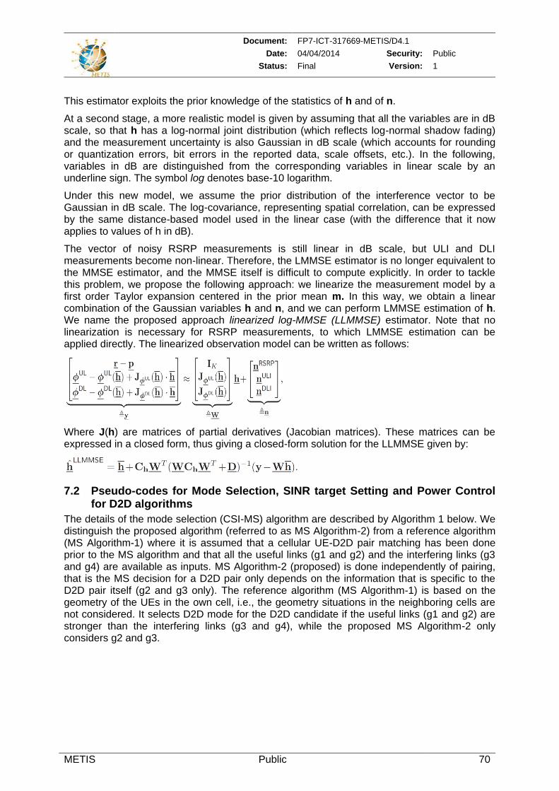
Document: FP7-ICT-317669-METIS/D4.1
Date: 04/04/2014 Security: Public
Status: Final Version: 1
METIS Public 70
This estimator exploits the prior knowledge of the statistics of h and of n.
At a second stage, a more realistic model is given by assuming that all the variables are in dB scale, so that h has a log-normal joint distribution (which reflects log-normal shadow fading) and the measurement uncertainty is also Gaussian in dB scale (which accounts for rounding or quantization errors, bit errors in the reported data, scale offsets, etc.). In the following, variables in dB are distinguished from the corresponding variables in linear scale by an underline sign. The symbol log denotes base-10 logarithm.
Under this new model, we assume the prior distribution of the interference vector to be Gaussian in dB scale. The log-covariance, representing spatial correlation, can be expressed by the same distance-based model used in the linear case (with the difference that it now applies to values of h in dB).
The vector of noisy RSRP measurements is still linear in dB scale, but ULI and DLI measurements become non-linear. Therefore, the LMMSE estimator is no longer equivalent to the MMSE estimator, and the MMSE itself is difficult to compute explicitly. In order to tackle this problem, we propose the following approach: we linearize the measurement model by a first order Taylor expansion centered in the prior mean m. In this way, we obtain a linear combination of the Gaussian variables h and n, and we can perform LMMSE estimation of h. We name the proposed approach linearized log-MMSE (LLMMSE) estimator. Note that no linearization is necessary for RSRP measurements, to which LMMSE estimation can be applied directly. The linearized observation model can be written as follows:
Where J(h) are matrices of partial derivatives (Jacobian matrices). These matrices can be expressed in a closed form, thus giving a closed-form solution for the LLMMSE given by:
7.2 Pseudo-codes for Mode Selection, SINR target Setting and Power Control for D2D algorithms
The details of the mode selection (CSI-MS) algorithm are described by Algorithm 1 below. We distinguish the proposed algorithm (referred to as MS Algorithm-2) from a reference algorithm (MS Algorithm-1) where it is assumed that a cellular UE-D2D pair matching has been done prior to the MS algorithm and that all the useful links (g1 and g2) and the interfering links (g3 and g4) are available as inputs. MS Algorithm-2 (proposed) is done independently of pairing, that is the MS decision for a D2D pair only depends on the information that is specific to the D2D pair itself (g2 and g3 only). The reference algorithm (MS Algorithm-1) is based on the geometry of the UEs in the own cell, i.e., the geometry situations in the neighboring cells are not considered. It selects D2D mode for the D2D candidate if the useful links (g1 and g2) are stronger than the interfering links (g3 and g4), while the proposed MS Algorithm-2 only considers g2 and g3.
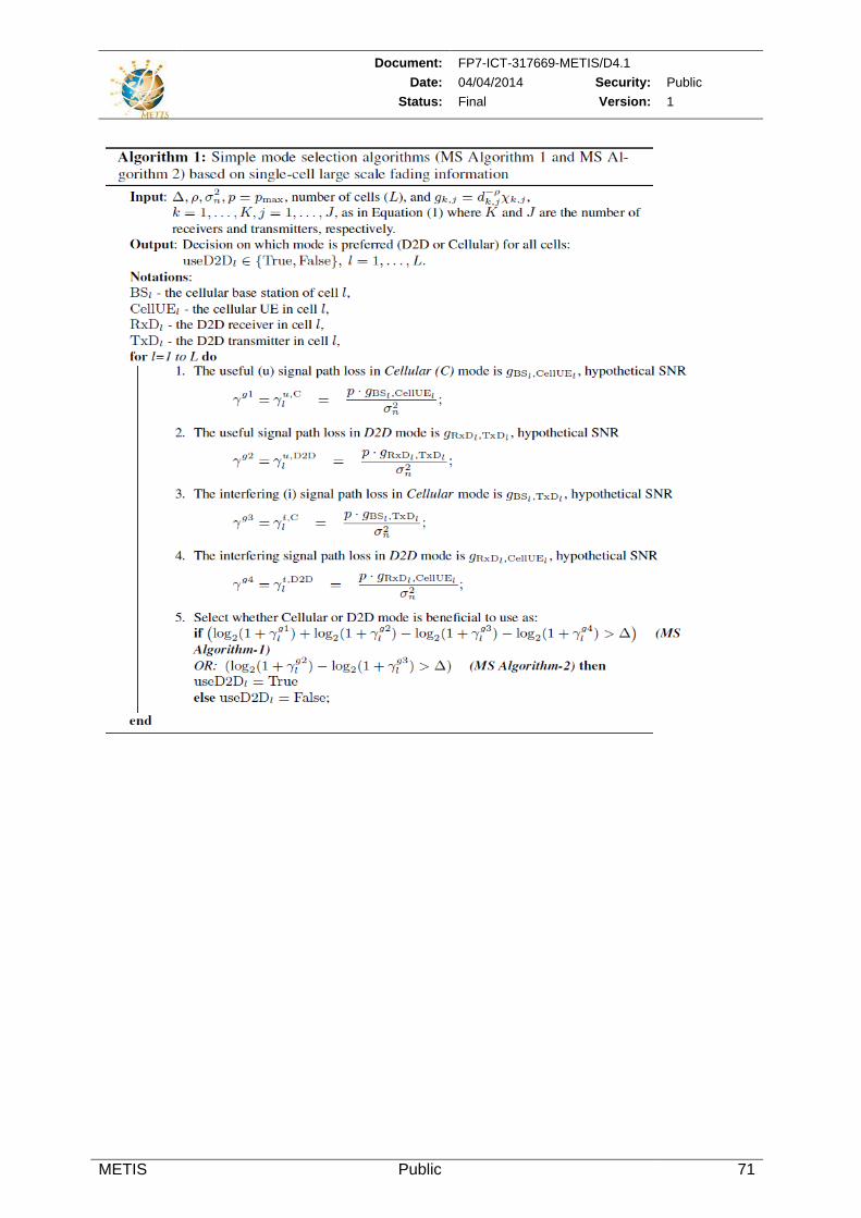
Document: FP7-ICT-317669-METIS/D4.1
Date: 04/04/2014 Security: Public
Status: Final Version: 1
METIS Public 71
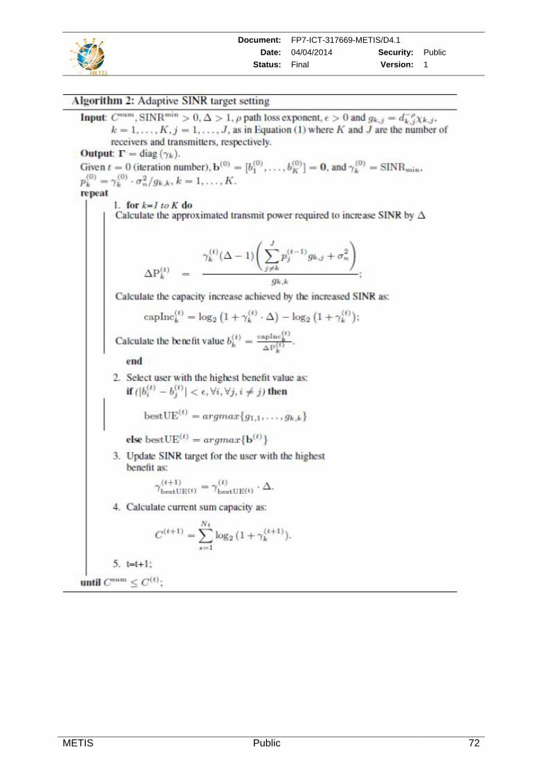
Document: FP7-ICT-317669-METIS/D4.1
Date: 04/04/2014 Security: Public
Status: Final Version: 1
METIS Public 72
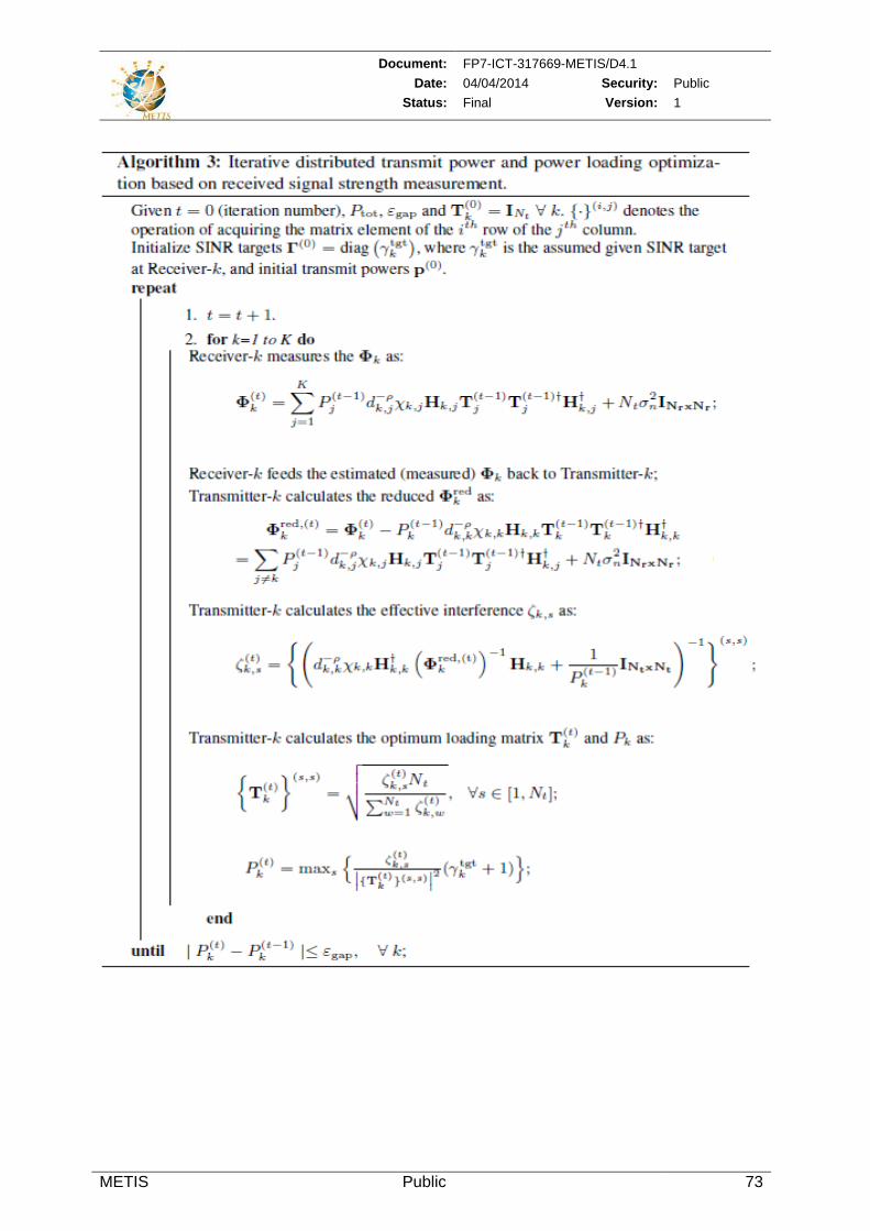
Document: FP7-ICT-317669-METIS/D4.1
Date: 04/04/2014 Security: Public
Status: Final Version: 1
METIS Public 73
Document: FP7-ICT-317669-METIS/D4.1
Date: 04/04/2014 Security: Public
Status: Final Version: 1
METIS Public 74
7.3 General cost minimization function for the exchange of context information
Regarding the design of the exchange flow In order to develop an efficient distribution schemes for the context information between the network entities, we define the design problem as a cost minimization problem. The considered cost consists of three parts, i.e. the CAPEX (capital expenditure) for the deployment and implementation of the corresponding context-aware functionality, the OPEX (operational expenditure) to execute the functionality regarding the computing cost and power consumption. It also includes additional maintenance costs (e.g. the software update) and the OPEX for the exchange of information, which includes the exchange of raw and modeled context information and the exchange of control signaling.
The objective function of the minimization problem is written as: min
Where CAPEX, OPEX1 and OPEX2 represent the cost functions corresponding to the costs described before.
We use AP,AS to denote the functional entities for the acquisition of the primary context information and the secondary context information, respectively, M for the modeling functionality, D for the decision making functionality and E for the control entity that receives
the results of decision making. , , , denote the position selection of the location of functional entity AP, AS, M, D with the index i, j, k, l, respectively in the network
architecture. defines the amount of the necessary information exchange between the functional entity x, y. It is worth noting that the cost for the information exchange is determined
by both the position selection of the functional entities , and the amount of exchanged
information .
Figure 7.3-1 illustrates the information exchange depending on the deployment of functional entities. According to the scope of this project, the functional entities, particularly the modeling and decision making entities are mainly implemented in the Radio Access Network. However, this scheme can also be extended to the core network and higher layer implementations.
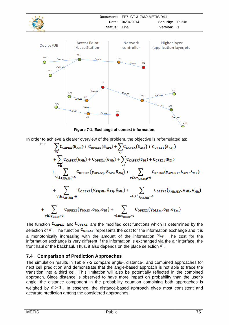
Document: FP7-ICT-317669-METIS/D4.1
Date: 04/04/2014 Security: Public
Status: Final Version: 1
METIS Public 75
Figure 7-1. Exchange of context information.
In order to achieve a clearer overview of the problem, the objective is reformulated as:
min
The function and are the modified cost functions which is determined by the
selection of . The function represents the cost for the information exchange and it is
a monotonically increasing with the amount of the information . The cost for the information exchange is very different if the information is exchanged via the air interface, the
front haul or the backhaul. Thus, it also depends on the place selection .
7.4 Comparison of Prediction Approaches
The simulation results in Table 7-2 compare angle-, distance-, and combined approaches for next cell prediction and demonstrate that the angle-based approach is not able to trace the transition into a third cell. This limitation will also be potentially reflected in the combined approach. Since distance is observed to have more impact on probability than the user’s angle, the distance component in the probability equation combining both approaches is
weighed by . In essence, the distance-based approach gives most consistent and accurate prediction among the considered approaches.
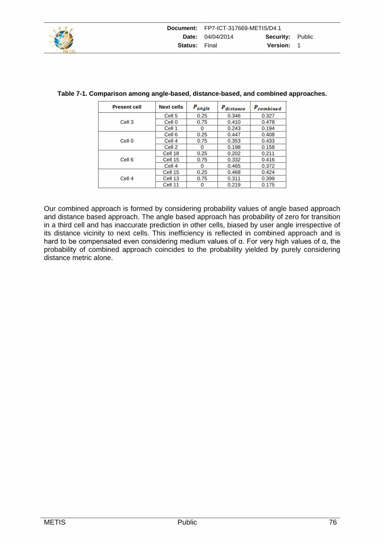
Document: FP7-ICT-317669-METIS/D4.1
Date: 04/04/2014 Security: Public
Status: Final Version: 1
METIS Public 76
Table 7-1. Comparison among angle-based, distance-based, and combined approaches.
Present cell Next cells
Cell 3
Cell 5 0.25 0.346 0.327
Cell 0 0.75 0.410 0.478
Cell 1 0 0.243 0.194
Cell 0
Cell 6 0.25 0.447 0.408
Cell 4 0.75 0.353 0.433
Cell 2 0 0.198 0.158
Cell 6
Cell 18 0.25 0.202 0.211
Cell 15 0.75 0.332 0.416
Cell 4 0 0.465 0.372
Cell 4
Cell 15 0.25 0.468 0.424
Cell 13 0.75 0.311 0.399
Cell 11 0 0.219 0.175
Our combined approach is formed by considering probability values of angle based approach and distance based approach. The angle based approach has probability of zero for transition in a third cell and has inaccurate prediction in other cells, biased by user angle irrespective of its distance vicinity to next cells. This inefficiency is reflected in combined approach and is hard to be compensated even considering medium values of α. For very high values of α, the probability of combined approach coincides to the probability yielded by purely considering distance metric alone.
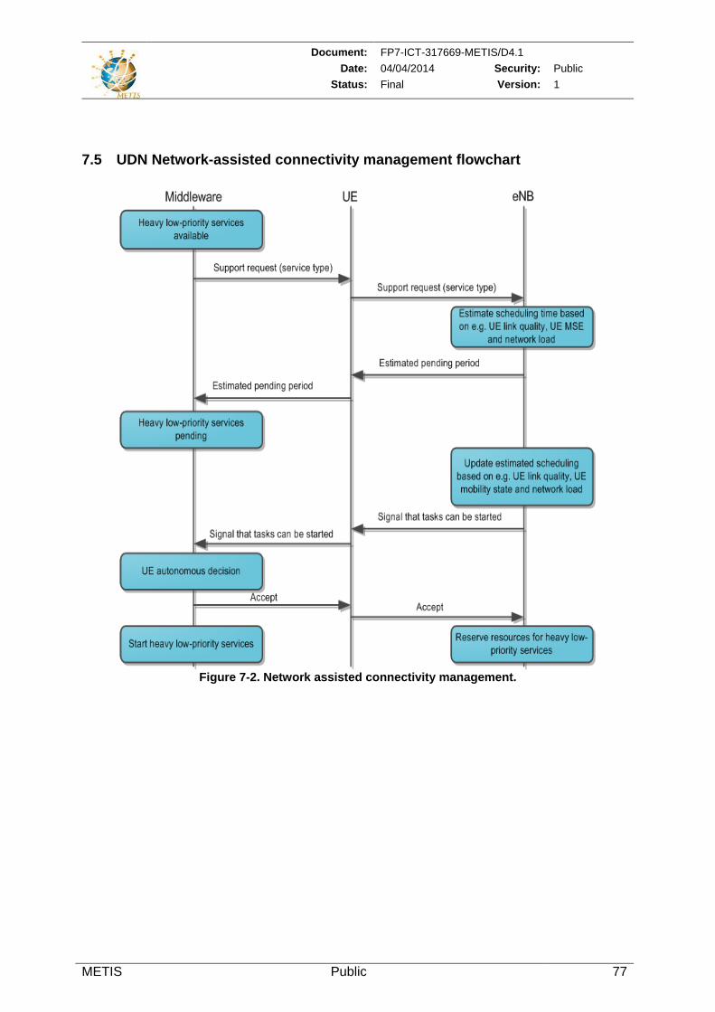
Document: FP7-ICT-317669-METIS/D4.1
Date: 04/04/2014 Security: Public
Status: Final Version: 1
METIS Public 77
7.5 UDN Network-assisted connectivity management flowchart
Figure 7-2. Network assisted connectivity management.
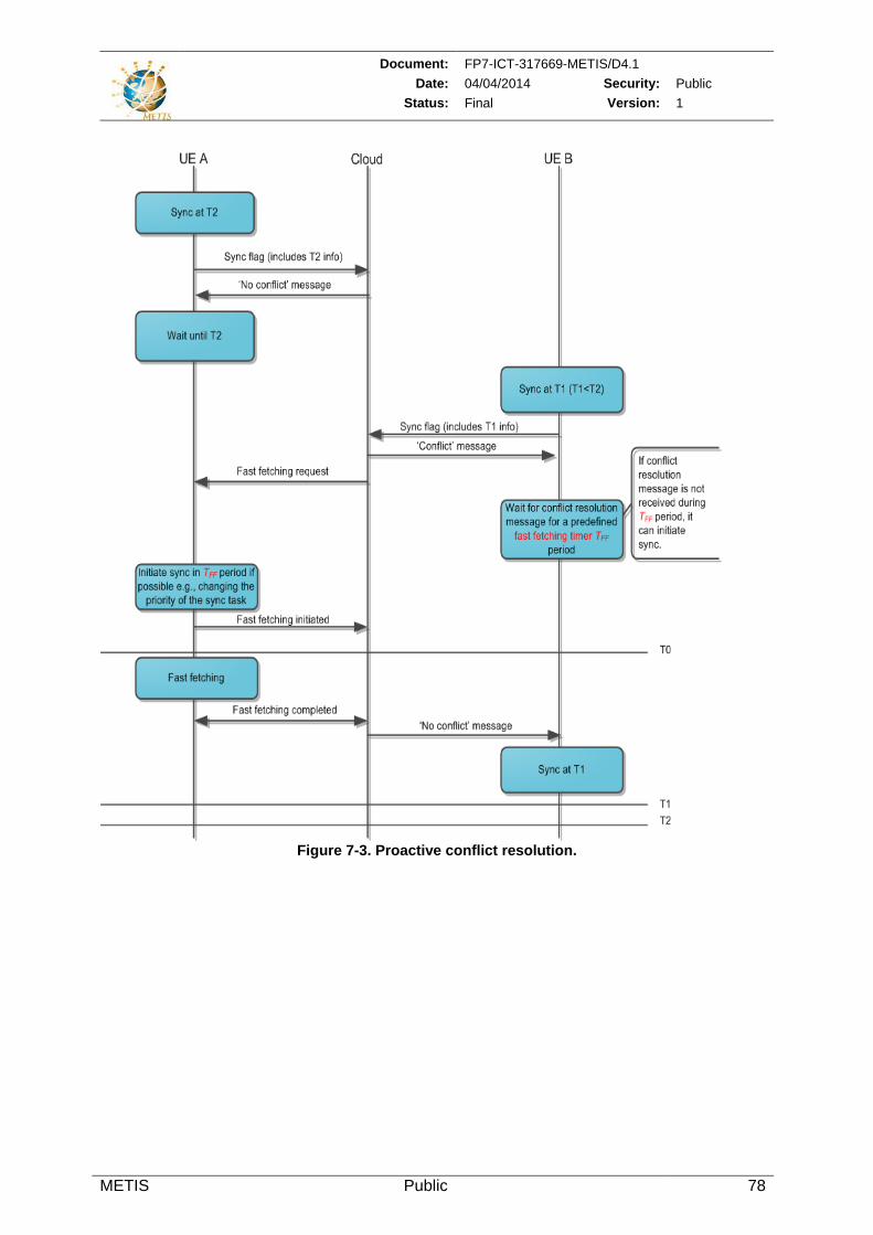
Document: FP7-ICT-317669-METIS/D4.1
Date: 04/04/2014 Security: Public
Status: Final Version: 1
METIS Public 78
Figure 7-3. Proactive conflict resolution.
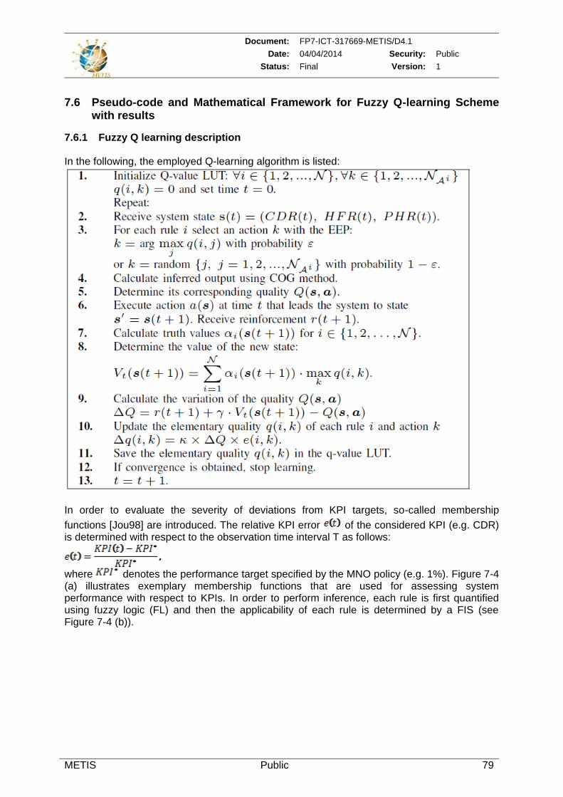
Document: FP7-ICT-317669-METIS/D4.1
Date: 04/04/2014 Security: Public
Status: Final Version: 1
METIS Public 79
7.6 Pseudo-code and Mathematical Framework for Fuzzy Q-learning Scheme with results
7.6.1 Fuzzy Q learning description In the following, the employed Q-learning algorithm is listed:
In order to evaluate the severity of deviations from KPI targets, so-called membership
functions [Jou98] are introduced. The relative KPI error of the considered KPI (e.g. CDR) is determined with respect to the observation time interval T as follows:
where denotes the performance target specified by the MNO policy (e.g. 1%). Figure 7-4 (a) illustrates exemplary membership functions that are used for assessing system performance with respect to KPIs. In order to perform inference, each rule is first quantified using fuzzy logic (FL) and then the applicability of each rule is determined by a FIS (see Figure 7-4 (b)).
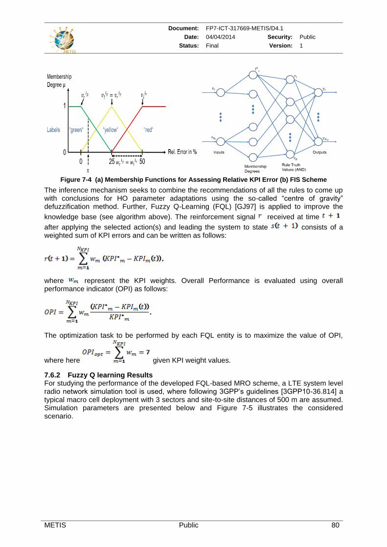
Document: FP7-ICT-317669-METIS/D4.1
Date: 04/04/2014 Security: Public
Status: Final Version: 1
METIS Public 80
Figure 7-4 (a) Membership Functions for Assessing Relative KPI Error (b) FIS Scheme
The inference mechanism seeks to combine the recommendations of all the rules to come up with conclusions for HO parameter adaptations using the so-called “centre of gravity” defuzzification method. Further, Fuzzy Q-Learning (FQL) [GJ97] is applied to improve the
knowledge base (see algorithm above). The reinforcement signal received at time
after applying the selected action(s) and leading the system to state consists of a weighted sum of KPI errors and can be written as follows:
where represent the KPI weights. Overall Performance is evaluated using overall performance indicator (OPI) as follows:
The optimization task to be performed by each FQL entity is to maximize the value of OPI,
where here given KPI weight values.
7.6.2 Fuzzy Q learning Results For studying the performance of the developed FQL-based MRO scheme, a LTE system level radio network simulation tool is used, where following 3GPP’s guidelines [3GPP10-36.814] a typical macro cell deployment with 3 sectors and site-to-site distances of 500 m are assumed. Simulation parameters are presented below and Figure 7-5 illustrates the considered scenario.
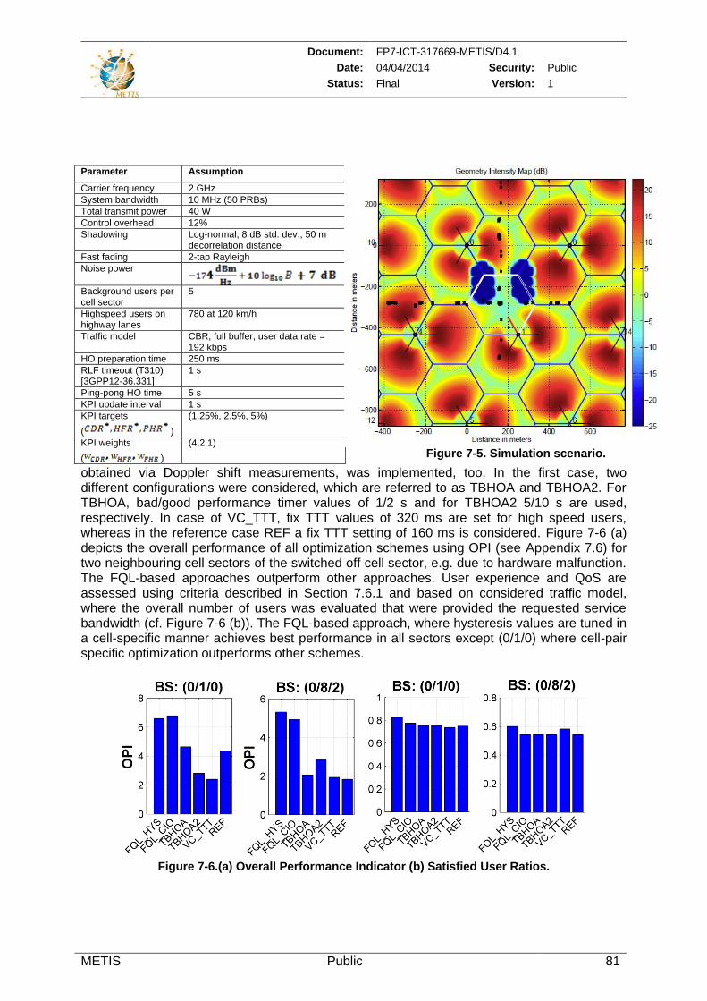
Document: FP7-ICT-317669-METIS/D4.1
Date: 04/04/2014 Security: Public
Status: Final Version: 1
METIS Public 81
For benchmarking the performance of the designed FQL-based MRO scheme, the trend-based MRO algorithm presented in [JBT+10], and a scheme that assigns TTT values based on velocity estimates (VC_TTT), which may be
obtained via Doppler shift measurements, was implemented, too. In the first case, two different configurations were considered, which are referred to as TBHOA and TBHOA2. For TBHOA, bad/good performance timer values of 1/2 s and for TBHOA2 5/10 s are used, respectively. In case of VC_TTT, fix TTT values of 320 ms are set for high speed users, whereas in the reference case REF a fix TTT setting of 160 ms is considered. Figure 7-6 (a) depicts the overall performance of all optimization schemes using OPI (see Appendix 7.6) for two neighbouring cell sectors of the switched off cell sector, e.g. due to hardware malfunction. The FQL-based approaches outperform other approaches. User experience and QoS are assessed using criteria described in Section 7.6.1 and based on considered traffic model, where the overall number of users was evaluated that were provided the requested service bandwidth (cf. Figure 7-6 (b)). The FQL-based approach, where hysteresis values are tuned in a cell-specific manner achieves best performance in all sectors except (0/1/0) where cell-pair specific optimization outperforms other schemes.
Figure 7-6.(a) Overall Performance Indicator (b) Satisfied User Ratios.
Parameter Assumption
Carrier frequency 2 GHz
System bandwidth 10 MHz (50 PRBs)
Total transmit power 40 W
Control overhead 12%
Shadowing Log-normal, 8 dB std. dev., 50 m decorrelation distance
Fast fading 2-tap Rayleigh
Noise power
Background users per cell sector
5
Highspeed users on highway lanes
780 at 120 km/h
Traffic model CBR, full buffer, user data rate = 192 kbps
HO preparation time 250 ms
RLF timeout (T310) [3GPP12-36.331]
1 s
Ping-pong HO time 5 s
KPI update interval 1 s
KPI targets
( )
(1.25%, 2.5%, 5%)
KPI weights
( )
(4,2,1)
Figure 7-5. Simulation scenario.
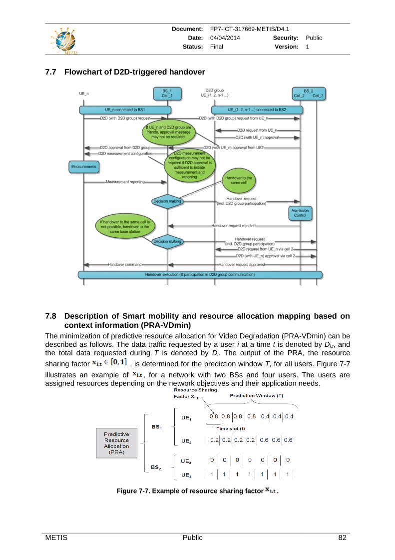
Document: FP7-ICT-317669-METIS/D4.1
Date: 04/04/2014 Security: Public
Status: Final Version: 1
METIS Public 82
7.7 Flowchart of D2D-triggered handover
7.8 Description of Smart mobility and resource allocation mapping based on context information (PRA-VDmin)
The minimization of predictive resource allocation for Video Degradation (PRA-VDmin) can be described as follows. The data traffic requested by a user i at a time t is denoted by Di,t, and the total data requested during T is denoted by Di. The output of the PRA, the resource
sharing factor , is determined for the prediction window T, for all users. Figure 7-7
illustrates an example of , for a network with two BSs and four users. The users are assigned resources depending on the network objectives and their application needs.
Figure 7-7. Example of resource sharing factor .
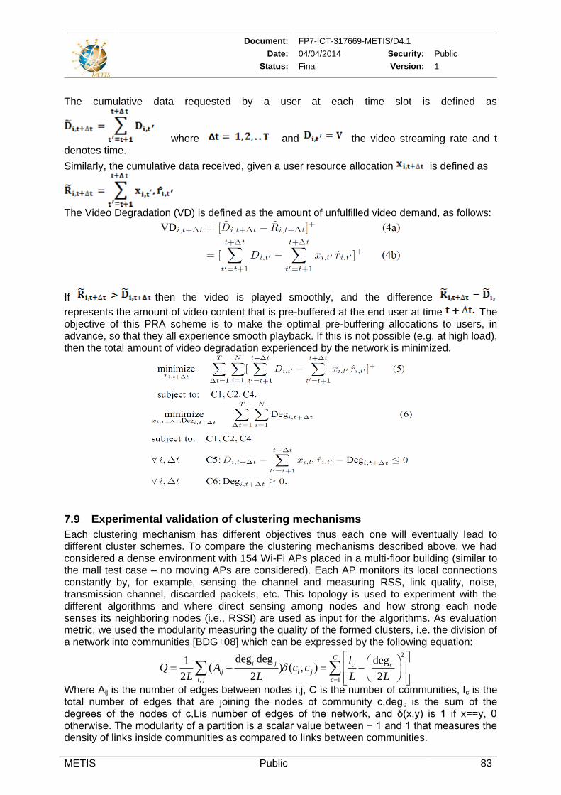
Document: FP7-ICT-317669-METIS/D4.1
Date: 04/04/2014 Security: Public
Status: Final Version: 1
METIS Public 83
The cumulative data requested by a user at each time slot is defined as
where and the video streaming rate and t denotes time.
Similarly, the cumulative data received, given a user resource allocation is defined as
The Video Degradation (VD) is defined as the amount of unfulfilled video demand, as follows:
If then the video is played smoothly, and the difference
represents the amount of video content that is pre-buffered at the end user at time The objective of this PRA scheme is to make the optimal pre-buffering allocations to users, in advance, so that they all experience smooth playback. If this is not possible (e.g. at high load), then the total amount of video degradation experienced by the network is minimized.
7.9 Experimental validation of clustering mechanisms
Each clustering mechanism has different objectives thus each one will eventually lead to different cluster schemes. To compare the clustering mechanisms described above, we had considered a dense environment with 154 Wi-Fi APs placed in a multi-floor building (similar to the mall test case – no moving APs are considered). Each AP monitors its local connections constantly by, for example, sensing the channel and measuring RSS, link quality, noise, transmission channel, discarded packets, etc. This topology is used to experiment with the different algorithms and where direct sensing among nodes and how strong each node senses its neighboring nodes (i.e., RSSI) are used as input for the algorithms. As evaluation metric, we used the modularity measuring the quality of the formed clusters, i.e. the division of a network into communities [BDG+08] which can be expressed by the following equation: Where Aij is the number of edges between nodes i,j, C is the number of communities, lc is the total number of edges that are joining the nodes of community c,degc is the sum of the degrees of the nodes of c,Lis number of edges of the network, and δ(x,y) is 1 if x==y, 0 otherwise. The modularity of a partition is a scalar value between − 1 and 1 that measures the density of links inside communities as compared to links between communities.
2
, 1
deg deg deg1( ) ( , )
2 2 2
Ci j c c
ij i j
i j c
lQ A c c
L L L L
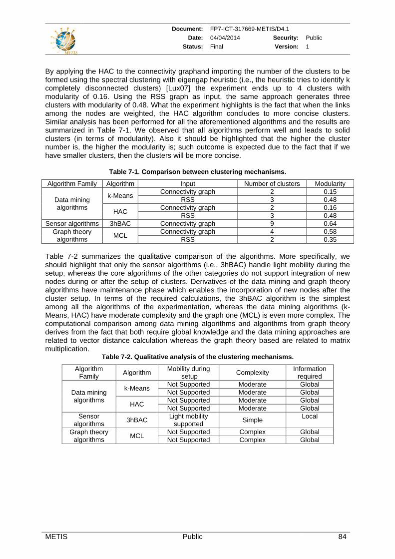
Document: FP7-ICT-317669-METIS/D4.1
Date: 04/04/2014 Security: Public
Status: Final Version: 1
METIS Public 84
By applying the HAC to the connectivity graphand importing the number of the clusters to be formed using the spectral clustering with eigengap heuristic (i.e., the heuristic tries to identify k completely disconnected clusters) [Lux07] the experiment ends up to 4 clusters with modularity of 0.16. Using the RSS graph as input, the same approach generates three clusters with modularity of 0.48. What the experiment highlights is the fact that when the links among the nodes are weighted, the HAC algorithm concludes to more concise clusters. Similar analysis has been performed for all the aforementioned algorithms and the results are summarized in Table 7-1. We observed that all algorithms perform well and leads to solid clusters (in terms of modularity). Also it should be highlighted that the higher the cluster number is, the higher the modularity is; such outcome is expected due to the fact that if we have smaller clusters, then the clusters will be more concise.
Table 7-1. Comparison between clustering mechanisms.
Algorithm Family Algorithm Input Number of clusters Modularity
Data mining algorithms
k-Means Connectivity graph 2 0.15
RSS 3 0.48
HAC Connectivity graph 2 0.16
RSS 3 0.48
Sensor algorithms 3hBAC Connectivity graph 9 0.64
Graph theory algorithms
MCL Connectivity graph 4 0.58
RSS 2 0.35
Table 7-2 summarizes the qualitative comparison of the algorithms. More specifically, we should highlight that only the sensor algorithms (i.e., 3hBAC) handle light mobility during the setup, whereas the core algorithms of the other categories do not support integration of new nodes during or after the setup of clusters. Derivatives of the data mining and graph theory algorithms have maintenance phase which enables the incorporation of new nodes after the cluster setup. In terms of the required calculations, the 3hBAC algorithm is the simplest among all the algorithms of the experimentation, whereas the data mining algorithms (k-Means, HAC) have moderate complexity and the graph one (MCL) is even more complex. The computational comparison among data mining algorithms and algorithms from graph theory derives from the fact that both require global knowledge and the data mining approaches are related to vector distance calculation whereas the graph theory based are related to matrix multiplication.
Table 7-2. Qualitative analysis of the clustering mechanisms.
Algorithm Family
Algorithm Mobility during
setup Complexity
Information required
Data mining algorithms
k-Means Not Supported Moderate Global
Not Supported Moderate Global
HAC Not Supported Moderate Global
Not Supported Moderate Global
Sensor algorithms
3hBAC Light mobility
supported Simple
Local
Graph theory algorithms
MCL Not Supported Complex Global
Not Supported Complex Global
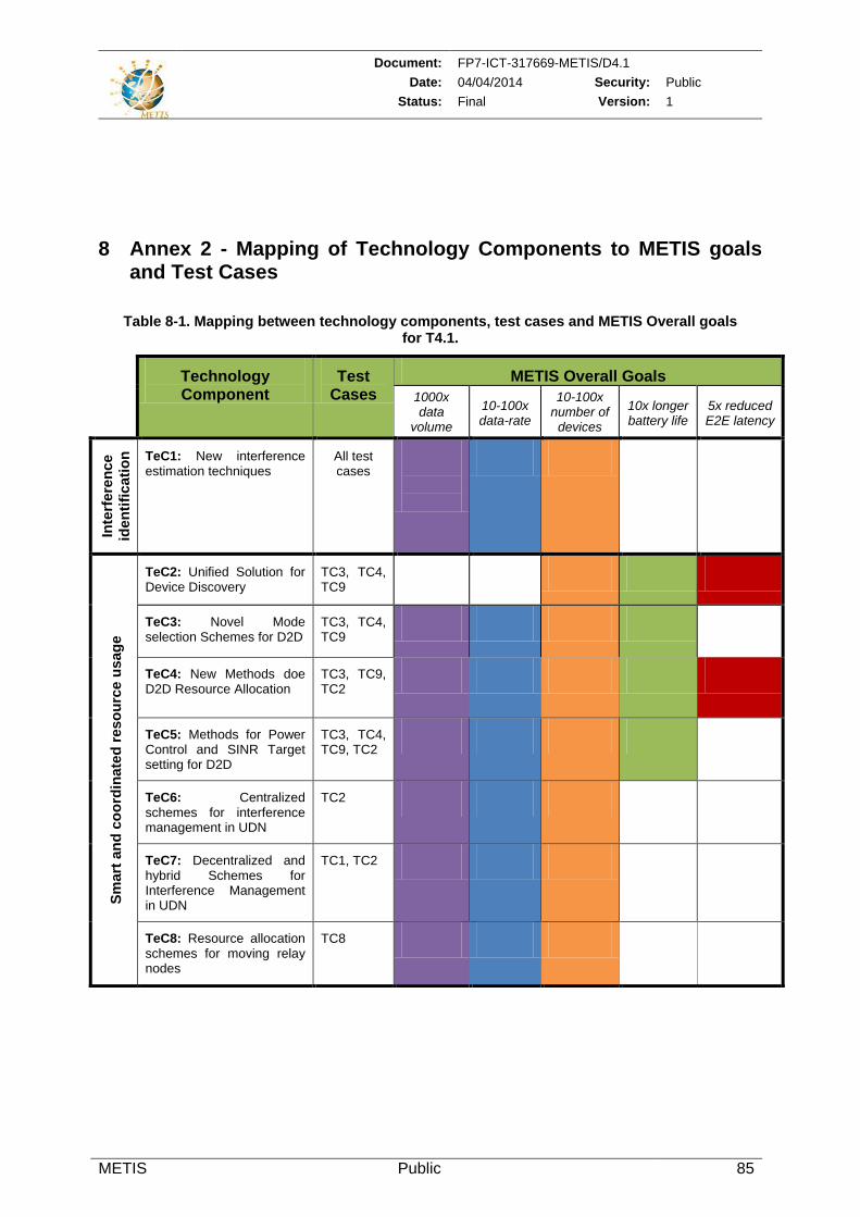
Document: FP7-ICT-317669-METIS/D4.1
Date: 04/04/2014 Security: Public
Status: Final Version: 1
METIS Public 85
8 Annex 2 - Mapping of Technology Components to METIS goals and Test Cases
Table 8-1. Mapping between technology components, test cases and METIS Overall goals for T4.1.
Technology Component
Test Cases
METIS Overall Goals
1000x data
volume
10-100x data-rate
10-100x number of devices
10x longer battery life
5x reduced E2E latency
Inte
rfe
ren
ce
ide
nti
fic
ati
on
TeC1: New interference estimation techniques
All test cases
Sm
art
an
d c
oo
rdin
ate
d r
es
ou
rce
us
ag
e
TeC2: Unified Solution for Device Discovery
TC3, TC4, TC9
TeC3: Novel Mode selection Schemes for D2D
TC3, TC4, TC9
TeC4: New Methods doe D2D Resource Allocation
TC3, TC9, TC2
TeC5: Methods for Power Control and SINR Target setting for D2D
TC3, TC4, TC9, TC2
TeC6: Centralized schemes for interference management in UDN
TC2
TeC7: Decentralized and hybrid Schemes for Interference Management in UDN
TC1, TC2
TeC8: Resource allocation schemes for moving relay nodes
TC8
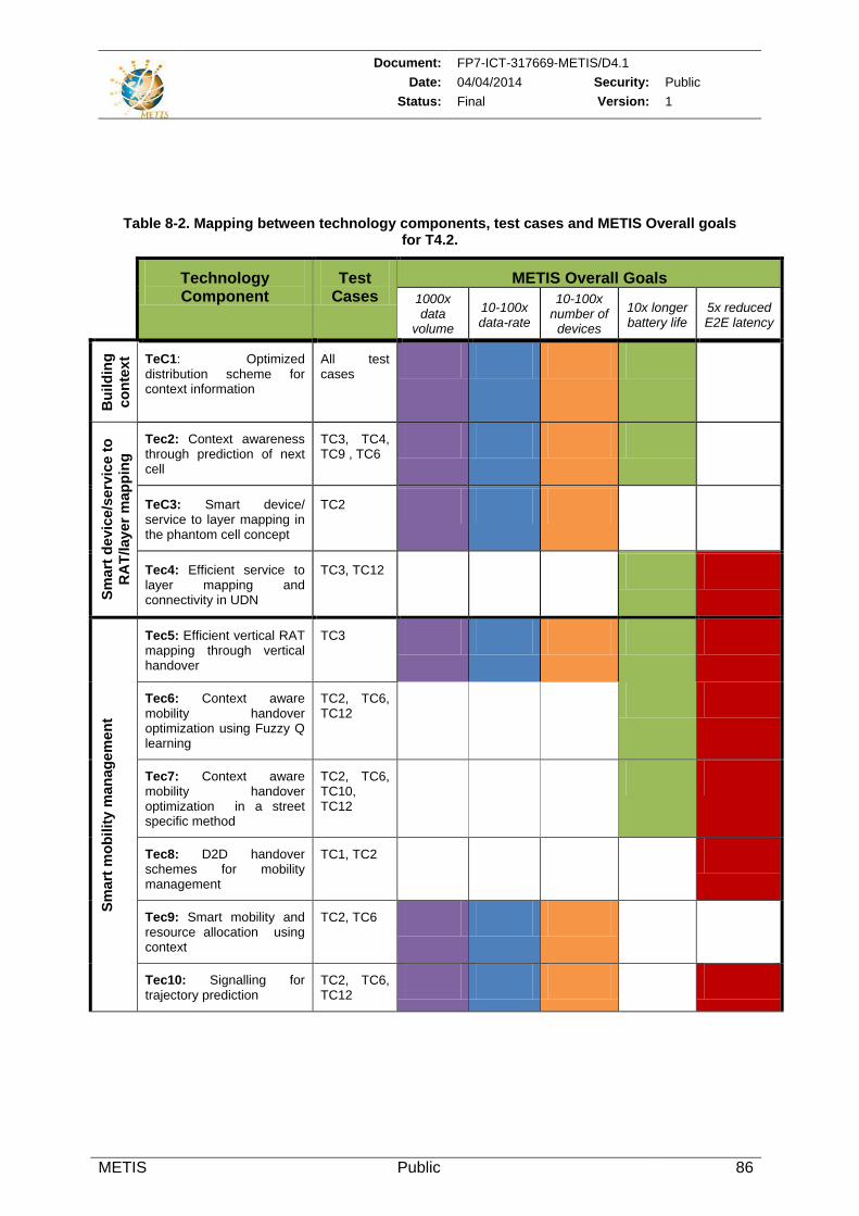
Document: FP7-ICT-317669-METIS/D4.1
Date: 04/04/2014 Security: Public
Status: Final Version: 1
METIS Public 86
Table 8-2. Mapping between technology components, test cases and METIS Overall goals for T4.2.
Technology Component
Test Cases
METIS Overall Goals
1000x data
volume
10-100x data-rate
10-100x number of devices
10x longer battery life
5x reduced E2E latency
Bu
ild
ing
co
nte
xt
aw
are
ne
ss
TeC1: Optimized distribution scheme for context information
All test cases
Sm
art
de
vic
e/s
erv
ice
to
RA
T/lay
er
ma
pp
ing
Tec2: Context awareness through prediction of next cell
TC3, TC4, TC9 , TC6
TeC3: Smart device/ service to layer mapping in the phantom cell concept
TC2
Tec4: Efficient service to layer mapping and connectivity in UDN
TC3, TC12
Sm
art
mo
bilit
y m
an
ag
em
en
t
Tec5: Efficient vertical RAT mapping through vertical handover
TC3
Tec6: Context aware mobility handover optimization using Fuzzy Q learning
TC2, TC6, TC12
Tec7: Context aware mobility handover optimization in a street specific method
TC2, TC6, TC10, TC12
Tec8: D2D handover schemes for mobility management
TC1, TC2
Tec9: Smart mobility and resource allocation using context
TC2, TC6
Tec10: Signalling for trajectory prediction
TC2, TC6, TC12