Embed Size (px)
Citation preview
IST Project N° 027568
Project co-funded by the European Commission within the Sixth Framework Programme (2002-2006)
Integrated Project
IRRIIS Integrated Risk Reduction of Information-based
Infrastructure Systems
Deliverable D 2.2.1
“Interdependency Taxonomy and
Interdependency Approaches”
Due date of deliverable: October 31, 2006
Actual submission date: June 4, 2007 Revision [3.0]
Organisation name of lead contractor for this deliverable:
IABG mbH Dissemination Level
PU Public
Start date of project: 01 February 2006 Duration: 3 years
Executive summary
D 2.1.1 Interdependency taxonomy 2
Author(s) Schmitz Walter (IABG)
Contributor(s) Felix Flentge (Fraunhofer IAIS) Hermann Dellwing (IABG) Christine Schwaegerl (Siemens)
Work package WP 2.2: “LCCI Interdependency Analysis” Task(s) Task 2.2.1: “Taxonomy of Interdependencies”
D 2.1.1 Interdependency taxonomy 3
Executive summary Information and Communication Technologies (ICT) today have become integral to virtually every domain of activity. These technologies are also part of so called Critical Information Infrastructures and support critical processes of almost every Critical Infrastructure. Critical Infrastructures are interconnected, dependent and interdependent via ICT in highly complex ways which are often surprisingly fragile. Addressing these problems for the long term requires a vigorous ongoing program of fundamental research to explore the science and to develop the technologies necessary to design resilience into information and communication networks from the ground up. A multidisciplinary approach to new R&D challenges in critical information infrastructure protection, both fundamental and applied, is strongly needed. The ICT-systems within the infrastructures play an important role in the data acquisition related to the infrastructures or the system monitoring, operation or control. The ever-increasing ICT-dependency of critical infrastructures makes the understanding of the vulnerabilities of the infrastructure systems very important. Other obvious reasons are the advent of new threats such as cyber attack or even cyber terror. The IRRIIS project (IST 027568) aims at increasing dependability, survivability and resilience of EU ICT-based critical information infrastructures. The basis for this work is the knowledge elicitation focused on interdependencies between the infrastructures “electricity” and “telecommunication including Internet”. This report describes the classification scheme used to provide a conceptual framework for discussion, analysis, and information retrieval concerning the different kinds of interdependencies. This report establishes an interdependency taxonomy derived from literature research and reflects corresponding methodological challenges to be addressed by IRRIIS: Chapter 1 addresses aim and scope of the interdependency analysis and specifies “dependency” and “interdependency” for the IRRIIS understanding: Dependency is the dependence of an infrastructure on commodities or services of other infrastructures and infrastructures are interdependent when each is dependent on the other. Chapter 2 illustrates the interdependent relationship among several infrastructures and exemplifies the importance of ICT-related interdependencies that transcend individual infrastructure sectors as well as individual private and public sector companies. Different types of failures can propagate through the “ICT-based network” of interdependent infrastructures and can cause blackouts. The analysis of cascading failures require a systems perspective and interdisciplinary skills. Chapter 3 describes dependency concepts and the corresponding terminology (taxonomy). Four principal classes of interdependencies are distinguished:
• Physical dependency: two infrastructures are physically dependent if the state of each is dependent on the material output(s) of the other.
• Cyber dependency: an infrastructure has a cyber dependency if its state depends on information transmitted through the information infrastructure.
• Geographic dependency: infrastructures are geographically dependent if a local environmental event can create state changes in all of them.
• Logical dependency: two infrastructures are logically dependent if the state of each depends on the state of the other via a mechanism that is not a physical, cyber, or geographic connection. The relationships on the international financial and commodity markets as well as the dependence on decisions of third parties (e.g. decisions of governments) represent logical dependencies.
D 2.1.1 Interdependency taxonomy 4
The behaviour of infrastructures is influenced by a broad range of interrelated factors and system conditions. The most important influence factors are: infrastructure environment, coupling and response behaviour of infrastructures, type of failures, infrastructure characteristics, states of operation. Metrics are needed as a common basis for the assessment of the system of mutual dependent infrastructures. Chapter 4 shows analogies between infrastructures and complex adaptive systems. Chapter 5 elaborates the need for interdisciplinary skills for dealing with interdependencies between LCCIs. Chapter 6 fixes the area of interest and constraints of the IRRIIS project. In this context IRRIIS confines to:
• Technical perspective: IRRIIS develops technologies to foster information exchange and to mitigate negative effects resulting from mutual dependencies and interdependencies between different infrastructures.
• Management perspective: The protection of critical infrastructures is seen as an issue of “service continuity” and covers technical level including organisational and human factors.
• Dependency perspective: Vulnerabilities based upon ICT-related dependencies and even interdependencies between “electricity” and “telecommunication / Internet” are the focus of IRRIIS.
• Geographical perspective: IRRIIS considers EU but case studies may be limited to single countries or trans-border regions depending on the availability of data.
• Time perspective: IRRIIS state-of-the-art solutions consider the time span from today to 2015.
Chapter 7 describes a general methodological approach how to analyse interdependent systems. In dealing with complex systems typical mistakes are made: Sub-optimisation and selection of inappropriate objective functions, inadequate modelling and inadequate solution strategies are often observed in dealing with complex systems. The main causes for these mistakes are: disconnection of the reality, disregard of control loops, and insufficient planning horizon. The challenge of a holistic methodological approach is to avoid these shortcomings and find answers on questions like:
• How does the system react to certain events? • How robust and flexible is it? • How can its behaviour be improved? • What are suitable leverages for control? • What are the critical and uncritical areas of the system?
The knowledge of the individual parts of a system is not enough to answer these questions. Also the knowledge of the cross-linking of the parts is necessary. Therefore a practicable process model for holistic CIP is introduced and showed that cybernetic interpretation – a method of networked thinking – can indeed produce quite accurate descriptions of system behaviour, even when working with rough data provided the cross-links are realised. Hints are given how the elements of a complex system can be classified and how the different methods can be used to analyse interdependent infrastructures. Chapter 8 analyses the general structure of cascading failures derived from historical outages. Typical scenario events and their sequence are described. It is intended to translate this structure into refined IRRIIS scenarios for case studies. Chapter 9 addresses some challenges of interdependency analysis mainly caused by manifold feedback loops which are the real cause of complexity. At the same time, feedback loops offer possibilities to control complex systems like interdependent critical infrastructures in order to keep their behaviour within reliable constraints. Suitable tools for such a control are
D 2.1.1 Interdependency taxonomy 5
communication and co-ordination which will be supported by IRRIIS MIT-components. In this respect chapter 9 builds a bridge to IRRIIS products like MIT components and MIT add-on components.
Foreword
Public life, economy and society as a whole depend to a very large extent on the proper functioning of large critical complex infrastructures (LCCIs) like electricity supply or telecommunication. The EU Integrated Project IRRIIS - Integrated Risk Reduction of Information-based Infrastructure Systems - aims at protecting these infrastructures (www.irriis.org).
This report was prepared as a part of the work carried out in the task 2.2.1 “Taxonomy of interdependencies” of the IRRIIS Work Package 2.2 “LCCI interdependency analysis: interdependency understanding”. The report summarises the result of the task 2.2.1.
The report was mainly written by people representing IABG, IRRIIS consortium participants involved in WP2.2 contributed to this deliverable.
D 2.1.1 Interdependency taxonomy 6
Contents
EXECUTIVE SUMMARY...........................................................................................................3
FOREWORD.................................................................................................................................5
CONTENTS...................................................................................................................................6
FIGURES .......................................................................................................................................9
TERMS AND DEFINITIONS....................................................................................................11
ABBREVIATIONS .....................................................................................................................17
1. INTRODUCTION...............................................................................................................19
1.2 Background.................................................................................................................................. 19
1.3 IRRIIS objectives ........................................................................................................................ 19
1.4 Aim and scope of the interdependency analysis ....................................................................... 19
1.5 Specification of the subject matter............................................................................................. 20
2. INTERDEPENDENCY: PROBLEM DESCRIPTION ...................................................21
2.1 Failures affecting the mutual dependent infrastructures ........................................................ 22
2.2 Threats ......................................................................................................................................... 23
3. TAXONOMY: DEPENDENCY CONCEPTS AND TERMINOLOGY........................25
3.1 Classes of Interdependencies: Terminology.............................................................................. 25
3.1.1 Physical dependency................................................................................................................. 25
3.1.2 Cyber dependency..................................................................................................................... 26
3.1.3 Geographic dependency............................................................................................................ 26
3.1.4 Logical dependency .................................................................................................................. 26
D 2.1.1 Interdependency taxonomy 7
3.2 Influence areas............................................................................................................................. 27
3.2.1 Infrastructure environment........................................................................................................ 27
3.2.2 Coupling and response behaviour ............................................................................................. 29
3.2.3 Granularity: Infrastructure characteristics ................................................................................ 31
3.2.4 Failure types.............................................................................................................................. 32
3.2.5 State of operation ...................................................................................................................... 33
3.2.6 Dependency effects [DPH02] ................................................................................................... 34
3.3 Recovering from disruptions [PFW01] ..................................................................................... 36
4. INFRASTRUCTURES AS COMPLEX ADAPTIVE SYSTEMS ..................................37
5. THE NEED FOR INTERDISCIPLINARY SKILLS [JP] ..............................................39
6. IRRIIS: AREA OF INTEREST AND CONSTRAINTS .................................................40
6.1 Electricity network [D1.2.1] ....................................................................................................... 40
6.2 Interdependencies between electricity and telecommunications ............................................ 47
7. METHODOLOGICAL APPROACH [WS03] .................................................................51
7.1 Risk and prevention .................................................................................................................... 51
7.2 Handling of complex systems ..................................................................................................... 51
7.3 Fundamentals of complex systems............................................................................................. 51
7.4 Prevalent shortcomings............................................................................................................... 52
7.4.1 Incorrect definition of objectives .............................................................................................. 52
7.4.2 Inadequate modelling of the system.......................................................................................... 52
7.4.3 Inadequate solution strategies ................................................................................................... 54
7.4.4 Sources of fault ......................................................................................................................... 54
7.4.5 Modelling and Simulation Challenges...................................................................................... 55
7.5 Process model for holistic CIP ................................................................................................... 56
D 2.1.1 Interdependency taxonomy 8
7.5.1 Step 1: Objectives and modelling of the problem situation ...................................................... 57
7.5.2 Step 2: Analysis of causality..................................................................................................... 59
7.5.3 Step 3: Scenario development................................................................................................... 61
7.5.4 Step 4: Impact analysis ............................................................................................................. 62
7.5.5 Step 5: Planning of strategies and measures ............................................................................. 63
7.5.6 Step 6: Realizing of robust and adaptable problem solutions ................................................... 64
7.6 Outlook......................................................................................................................................... 64
7.7 Course of action using different methods.................................................................................. 65
7.7.1 Quick-look analysis [BBB04]................................................................................................... 66
7.7.2 System Dynamics...................................................................................................................... 67
7.7.3 Agent-based models.................................................................................................................. 67
7.7.4 Graphs [GV04].......................................................................................................................... 68
8. GENERIC STRUCTURE OF CASCADING FAILURES..............................................69
9. INTERDEPENDENCY CHALLENGES..........................................................................71
9.1 Holistic approach......................................................................................................................... 72
9.2 Holistic consideration of accidents............................................................................................. 73
9.3 Co-ordination............................................................................................................................... 77
10. REFERENCES................................................................................................................79
D 2.1.1 Interdependency taxonomy 9
Figures
Figure 1: Examples of infrastructure interdependencies...............................................................22
Figure 2: Examples of Cascading and Escalating Failures (source: [JP]).....................................23
Figure 3: Interdependency taxonomy............................................................................................25
Figure 4: Linear and complex interactions....................................................................................30
Figure 5: Synchronous, slightly shifted dependence (source: [DPH02])......................................35
Figure 6: Possible characteristics of damage, infrastructure B without any reserve (source: [DPH02]) .......................................................................................................................................35
Figure 7: Possible characteristics of damage, infrastructure B with reserves (source: [DPH02]) 35
Figure 8: Asynchronous dependence (source: [DPH02]) .............................................................36
Figure 9: The electric power system (Streit, 2006).......................................................................41
Figure 10: Today’s Electric power system....................................................................................41
Figure 11: Network transformer, machine transformer ................................................................42
Figure 12: Air insolated HV substation.........................................................................................42
Figure 13: Gas insolated HV substation........................................................................................43
Figure 14: Hybrid type HV substation ..........................................................................................43
Figure 15: Examples of HV circuit breaker, a) 3 pole b) dead tank .........................................44
Figure 16: Examples of MV circuit breaker..................................................................................44
Figure 17: MV and LV substations ...............................................................................................44
Figure 18: Construction of switchgear in MV substation .............................................................45
Figure 19: ICT dependency of electricity (Streit, 2006) ...............................................................46
Figure 20: ICT dependence of SCADA system............................................................................46
Figure 21: Electricity and telecommunication system organisation ............................................49
Figure 22: Examples of dependences of telecommunication, electric power system and stakeholders (source: Antonio Diu 2006)......................................................................................50
Figure 23: CIP process model .......................................................................................................57
Figure 24: Hierarchy levels ...........................................................................................................58
Figure 25: CIP control model........................................................................................................59
D 2.1.1 Interdependency taxonomy 10
Figure 26: System of interdependent critical infrastructures ........................................................60
Figure 27: The roles of the elements.............................................................................................61
Figure 28: Hierarchical Structure..................................................................................................62
Figure 29: Regulator and interdependent critical infrastructures..................................................63
Figure 30: Self-regulation processes .............................................................................................64
Figure 31: Risk-based infrastructure interdependency assessment process [BBB04] ..................65
Figure 32: General model of socio-technical control....................................................................74
Figure 33: A hierarchical three-level control loop ........................................................................75
Figure 34: Dependability model in SoS ........................................................................................76
Figure 35: Co-ordination patterns .................................................................................................77
Figure 36: Communication and co-ordination in different phases................................................78
D 2.1.1 Interdependency taxonomy 11
Terms and Definitions
Agent
An agent is an entity with a location, capabilities, and memory.
Catastrophic Failure
A catastrophic failure is defined as one that results in the outage of sizable amount of load / traffic. It may be caused by dynamic instabilities in the system or exhaustion of the reserves.
CIP versus CIIP
A clear and stringent distinction between the two key terms “CIP” (Critical Infrastructure Protection) and “CIIP” (Critical Information Infrastructure Protection) is to be made. CIP is more than CIIP, but CIIP is an essential part of CIP. There is at least one characteristic for the distinction of the two concepts: While CIP comprises all critical sectors of a nation’s infrastructure, CIIP is only a subset of a comprehensive protection effort, as it focuses on the critical information infrastructure. But in official publications, both terms are often used inconsistently.
Complex adaptive system (CAS)
CAS is a collection of interacting components in which change often occurs as a result of learning processes. From a CAS perspective, infrastructures are more than just an aggregation of their components. Typically, as large sets of components are brought together and interact with one another, synergies emerge.
Critical Infrastructure (CI)
A critical infrastructure (CI) consists of those physical and information technology facilities, networks, services and assets which, if disrupted or destroyed, have a serious impact on the health, safety, security or economic well-being of citizens or the effective functioning of governments ([EU05]).
Critical Information Infrastructure (CII)
A critical information infrastructure (CII) consists of those information and communication technology facilities, networks, services and assets which, if disrupted or destroyed, either (1) have a serious impact on the health, safety, security or economic well-being of citizens or the effective functioning of governments, or (2) causes the functioning of a critical infrastructure which it supports to be seriously disrupted.
Critical Information Infrastructure Protection (CIIP)
D 2.1.1 Interdependency taxonomy 12
The programs and activities of infrastructure owners, manufacturers, users, operators and regulatory authorities which aim at keeping the performance of critical information infrastructures in case of failures, attacks or accidents above a defined minimum level of services and aim at minimising the recovery time and damage.
Critical Infrastructure Protection (CIP)
The programs and activities of infrastructure owners, manufacturers, users, operators and regulatory authorities which aim at keeping the performance of critical infrastructures in case of natural disasters, failures, human error, attacks or accidents above a defined minimum level of services and aim at minimising the recovery time and damage.
Dependability
Dependability of a service is the fulfilment of the following criteria: • availability: readiness for correct service • reliability: continuity of correct service • safety: absence of catastrophic consequences on the user(s) and the environment • confidentiality: absence of unauthorized disclosure of information • integrity: absence of improper system state alterations • maintainability: ability to undergo modifications and repairs.
Dependency
Dependency is either a link or a connection between two products or services, through which the state of one influences or correlates to the state of the other [AC03]. In this context, it describes a specific, individual connection between two infrastructures, such as the electricity used to power a telecommunications switch. Usually this relationship is unidirectional.
Emergent behaviour
Simply aggregating the components in an ad hoc fashion will not ensure reliable output. Only the exploitation of synergies by the careful creation of an intricate set of services will yield a system that reliably and continuously supplies electricity. This additional complexity exhibited by a system as a whole, beyond the simple sum of its parts, is called emergent behaviour
Error
An error is the specific part of the system state that is liable to lead to subsequent failure.
Failure
A system failure occurs when the delivered service deviates from fulfilling the system function as specified.
Fault
Fault is the adjudged cause of an error.
Information systems security
D 2.1.1 Interdependency taxonomy 13
Information system security is defined to be those actions that are taken to ensure the integrity, confidentiality, non-repudiation, availability, timely access to authorised users, and authentication of (a defined set of) information and communication systems. This includes information that is stored, processed, or transmitted
Infrastructure (I)
An infrastructure forms a framework of (inter)dependent networks and systems comprising identifiable industries, institutions (including people and procedures), and/or distribution capabilities that provide a reliable flow of products, supplies and/or services, for the smooth functioning of governments at all levels, economy and society as a whole and of other infrastructures.
Interdependency
Interdependency is a bi-directional relationship between two infrastructures through which the state of each infrastructure influences or is correlated to the state of the other. More generally, two infrastructures are interdependent when each is dependent on the other.
Internet
In this report it means a public network which uses TCP/IP (or UDP/IP) protocol family.
Intrusion
The term “intrusion” is used to describe the type of fault caused by exploitation of vulnerability.
Metrics
Metrics are a system of parameters or ways of quantitative and periodic assessment of a process that is to be measured, along with the procedures to carry out such measurement and the procedures for the interpretation of the assessment in the light of previous or comparable assessments. Metrics are usually specialized by the subject area, in which case they are valid only within a certain domain and cannot be directly interpreted outside it. Metrics are used to measure the effectiveness of the various processes at delivering Services to Customers.
MIT
MIT is a concrete target of the IRRIIS project (besides the SIMCIP simulation environment). MIT (Middleware Improved Technology) is a collection of software components, which facilitates IT-based communication between different infrastructures and different infrastructure providers.
Pseudonymity
Pseudonymity is a word derived from pseudonym, meaning 'pen name', and describes a state of disguised identity resulting from the use of a pseudonym (also called nym). The pseudonym identifies a holder, that is, one or more human beings who possess but do not disclose their true names (that is, legal identities). For example, all of the Federalist Papers were signed by Publius, a pseudonym representing the trio of James Madison, Alexander Hamilton, and John Jay. As this example suggests, most pseudonym holders use pseudonyms because they wish to remain anonymous. But anonymity is difficult to achieve, and is often fraught with legal issues. True
D 2.1.1 Interdependency taxonomy 14
anonymity requires unlinkability, such that an attacker's examination of the pseudonym holder's message provides no new information about the holder's true name.
Protection Relay
A protection relay is a complex electromechanical apparatus, often with more than one coil, designed to calculate operating conditions on an electrical circuit and trip circuit breakers when a fault was found. Unlike switching type relays with fixed and usually ill-defined operating voltage thresholds and operating times, protection relays had well-established, selectable, time/current (or other operating parameter) curves. Such relays were very elaborate, using arrays of induction disks, shaded-pole magnets, operating and restraint coils, solenoid-type operators, telephone-relay style contacts, and phase-shifting networks to allow the relay to respond to such conditions as over-current, over-voltage, reverse power flow, over- and under- frequency, and even distance relays that would trip for faults up to a certain distance away from a substation but not beyond that point. An important transmission line or generator unit would have had cubicles dedicated to protection, with a score of individual electromechanical devices. Each of the protective functions available on a given relay are denoted by standard ANSI Device Numbers. For example, a relay including function 51 would be a timed overcurrent protection relay.
Design and theory of these protective devices is an important part of the education of an electrical engineer who specializes in power systems. Today these devices are nearly entirely replaced (in new designs) with microprocessor-based instruments (numerical relays) that emulate their electromechanical ancestors with great precision and convenience in application. By combining several functions in one case, numerical relays also save capital cost and maintenance cost over electromechanical relays. However, due to their very long life span, tens of thousands of these "silent sentinels" are still protecting transmission lines and electrical apparatus all over the world.
Relay A relay is an electrical switch that opens and closes under control of another electrical circuit. In the original form, the switch is operated by an electromagnet to open or close one or many sets of contacts. Because a relay is able to control an output circuit of higher power than the input circuit, it can be considered, in a broad sense, to be a form of electrical amplifier. These contacts can be either Normally Open (NO), Normally Closed (NC), or change-over contacts.
• Normally-open contacts connect the circuit when the relay is activated; the circuit is disconnected when the relay is inactive. It is also called Form A contact or "make" contact. Form A contact is ideal for applications that require to switch a high-current power source from a remote device.
• Normally-closed contacts disconnect the circuit when the relay is activated; the circuit is connected when the relay is inactive. It is also called Form B contact or "break" contact. Form B contact is ideal for applications that require the circuit to remain closed until the relay is activated.
• Change-over contacts control two circuits: one normally-open contact and one normally-closed contact with a common terminal. It is also called Form C contact.
Reliability
D 2.1.1 Interdependency taxonomy 15
Reliability is the ability of a system to perform and maintain its functions in routine circumstances, as well as hostile or unexpected circumstances.
Resilience
Resilience is the ability to recover from (or resist being affected by) some disturbance, shock, or insult.
Scenario
Scenario is a basic concept of scenario thinking and the outline of a thinkable future situation. It includes the description of the future world and the path or route from the current state of the world to the future one.
SimCIP
SimCIP is a concrete target of the IRRIIS project (besides the MIT component). SimCIP is a synthetic simulation environment for controlled CIP experimentation with a special focus on LCCIs dependencies. The simulator will be used to deepen the understanding of critical infrastructures and their interdependencies, to identify possible problems, to develop appropriate solutions and to validate and test the MIT components.
Steganography
Steganography is the art and science of writing hidden messages in such a way that no one apart from the intended recipient knows of the existence of the message; this is in contrast to cryptography, where the existence of the message itself is not disguised, but the content is obscured. Generally, a steganographic message will appear to be something else: a picture, an article, a shopping list, or some other message - the covertext. The advantage of steganography over cryptography alone is that messages do not attract attention to themselves, to messengers, or to recipients. Steganography uses in electronic communication include steganographic coding inside of a transport layer, such as an MP3 file, or a protocol, such as UDP.
Survivability
Survivability is the quantified ability of a system, subsystem, equipment, process, or procedure to continue to function during and after a natural or man-made disturbance.
Switch A switch is a device for changing the course (or flow) of a circuit. The prototypical model is a mechanical device (for example a railroad switch) which can be disconnected from one course and connected to another. The term "switch" typically refers to electrical power or electronic telecommunication circuits. In applications where multiple switching options are required (e.g., a telephone service), mechanical switches have long been replaced by electronic variants which can be intelligently controlled and automated. The switch is referred to as a "gate" when abstracted to mathematical form. In the philosophy of logic, operational arguments are represented as logic gates. The use of electronic gates to function as a system of logical gates is the fundamental basis for the computer—i.e. a computer is a system of electronic switches which function as logical gates.
Taxonomy
D 2.1.1 Interdependency taxonomy 16
Taxonomy was once only the science of classifying living organisms (alpha taxonomy), but later the word was applied in a wider sense, and may also refer to either a classification of things, or the principles underlying the classification. Almost anything, animate objects, inanimate objects, places, and events, may be classified according to some taxonomic scheme.
Vulnerability
Vulnerability is a weakness of system that can be exploited with malicious intent creating a malicious error and possible failure.
D 2.1.1 Interdependency taxonomy 17
Abbreviations
AC Alternating Current
CAS Complex Adaptive System
CI Critical Infrastructure
CII Critical Information Infrastructure
CIP Critical Infrastructure Protection
CIIP Critical Information Infrastructure Protection
CO Central Office
DC Direct Current
DG Distributed Generation
DSO Distribution System Operator
EHV Extra-High Voltage EMS Energy Management System
EPS Electric Power System
EU European Union
FACTS Flexible AC Transmission System
GSM Global System for Mobile Communications
GSM-R GSM-Railway
HV High Voltage
HVDC High-Voltage Direct Current
ICT Information and Communication Technology
IEEE Institute of Electrical and Electronics Engineers
IRRIIS Integrated Risk Reduction of Information-based Infrastructure Systems
IT Information Technology
LCCI Large Critical Complex Infrastructure
LV Low Voltage
MIT Middleware Improved Technology
D 2.1.1 Interdependency taxonomy 18
MV Medium Voltage
MVDC Medium-Voltage Direct Current
PMR Professional Mobile Radio
POP Point of Presence
PSTN Public Switched Telephone Network
R&D Research and Development
RTU Remote Terminal Unit
SCADA Supervisory Control and Data Acquisition
SLA Service Level Agreement
SoS System of Systems
SimCIP Simulation Environment for CIP Experimentation and Exercises
STAMP System-Theoretic Accident Modelling and Processes
TCP/IP Transmission Control Protocol / Internet Protocol
TETRA Terrestrial Trunked Radio
TSO Transmission System Operator
UDP/IP User Datagram Protocol / Internet Protocol
UMTS Universal Mobile Telecommunications System
VPN Virtual Private Network
xDSL x Digital Subscriber Line
3G Third-generation mobile phone technology
D 2.1.1 Interdependency taxonomy 19
1. Introduction
1.2 Background
Infrastructures have undergone drastic changes in the last decades. The ubiquitous use of ICT has pervaded in all traditional infrastructures, rendering them more intelligent, increasingly interconnected, complex, interdependent, and therefore more vulnerable. Infrastructure systems are to a very large extent dependent on complex ICT. Due to this ICT-dependency infrastructures have also become more dependent on each other, especially on the telecommunication infrastructure.
Currently, no comprehensive approaches based on emerging systematic and holistic theories and methodologies on LCCIs are available.
The existing knowledge of the dependencies and interdependencies and related potential risks of cascading effects is still insufficient to provide immediate solutions.
1.3 IRRIIS objectives
The IRRIIS project will investigate the phenomena of dependencies and interdependencies and of cascading effects in cases of faults or disruptions. It will develop improved concepts and demonstrate selected ICT-based solutions to overcome existing and developing risk factors.
The overall objective of the IRRIIS project is formulated in the Description of Work-document as follows:
to enhance substantially the dependability of LCCIs by introducing appropriate MIT components within the next three years
1.4 Aim and scope of the interdependency analysis
The IRRIIS sub-project 2 “LCCI analysis” started with work-package WP 2.1 “LCCI Topology Analysis” where the main LCCI data problems (objects and interrelationships between the objects) will be identified and state-of-the-art of models in use within the selected fields “electricity supply” and “telecommunication” as examples for critical infrastructures. Work-package WP 2.2 “LCCI interdependency analysis: interdependency understanding” was also started in the very beginning of the sub-project SP2. This report summarises the results of the Task 2.2.1 “Taxonomy of interdependencies” and presents the developed interdependency taxonomy related to the critical infrastructures “electricity” and “telecommunication”.
Characteristics of LCCI complexity are:
• Interdependency of LCCIs: one event in one part of one LCCI can create a global effect by cascading throughout the same LCCI and even into other LCCIs,
• Adaptive reconfiguration of LCCI components, subsystems and systems to events and surroundings,
D 2.1.1 Interdependency taxonomy 20
• Systems belonging to LCCIs are often spread across vast distances, are non-linear, heterogeneous, and highly interactive. Each system may have hierarchical layers and may be distributed at each layer,
• in each situation LCCIs are subject to natural disasters, attacks, and unusually high demand,
• LCCIs are not created at once but evolve over years.
In summary, WP2.2 analyses the “mechanics” of cascading effects between infrastructures in order to:
• achieve understanding of interdependencies and develop control and cooperation methods for mutually dependent LCCIs,
• identify weak points and critical interface structures between interdependent LCCIs, • analyse inherent self-control, self-protecting mechanisms between infrastructures, • support strategy development for better dependability and security of the system of
infrastructures, • supply tools and techniques for an cost-efficient design of robust connecting interface
structures between the LCCIs, • formulate strategies for a robust management of interacting LCCI networks.
This interdependency analysis is aiming at a better co-operation between the interdependent LCCIs “electricity” and “telecommunication”. The aim of the task 2.2.1 is to develop a classification scheme used to provide a conceptual framework for discussion, analysis, and information retrieval concerning the different kinds of interdependencies (taxonomy of interdependencies). 1.5 Specification of the subject matter
Up to now the topic “interdependency” is not yet exhausted and there is no concrete classification of the concepts or systematic research into the different characteristics of interdependencies. The item “interdependency” as denotation for dependences in critical infrastructures has established. But a differentiation of dependencies and interdependencies would be more selective because the item “interdependency” indicates a mutual dependence. Therefore the more general term “dependency” will be used in this report when the direction of the relationship is irrelevant.
Denotation 1: “Dependency” Dependency is the complete or partial dependence of an infrastructure on commodities or services of one or more other infrastructures.
Denotation 2: “Interdependency” Interdependency is a bi-directional relationship between two infrastructures through which the state of each infrastructure influences or is correlated to the state of the other. More generally, two infrastructures are interdependent when each is dependent on the other (see [RPK01])
The level of operativeness of an infrastructure becomes more important. The outage of an infrastructure does not mean automatically the outage of the dependent infrastructure; the operativeness could also be only shortened.
Therefore “dependencies” and “interdependencies” will be delineated via “impact” and “effect” [DPH02]:
D 2.1.1 Interdependency taxonomy 21
“Impact” deals with the questions: • Does dependence exist between commodities or services of the considered
infrastructures? • Who is dependent on whom? (direction of the dependence)
“Effect” describes • the intensity and • the time-frame of the dependences.
First questions are: Is telecommunication dependent on electricity supply? Is electricity dependent on telecommunication services? Who relies on which commodities (e.g. electricity) and services (e.g. service level agreement)?
Follow-on questions are: How strongly is telecommunication dependent on electricity? How long can the telecommunication sector offer its services without electricity supply of the energy sector? How strongly is electricity dependent on telecommunication? How does the introduction of new processes influence the crisis management or the usage of new technologies (e.g. MIT)? Can they reduce or even eliminate the intensity of the dependency?
2. Interdependency: Problem description Interdependency analysis is a new discipline and it is a significant challenge to identify, understand, and analyse (inter)dependencies. Neither a common terminology nor agreed metrics are introduced up to now as a basis for the assessment of the system of mutual dependent infrastructures. This chapter provides an overview of infrastructure (inter)dependency concepts and terminology and highlights the need for an interdisciplinary approach. It is mainly based on literature investigation e.g. [JP], [RPK01], [PFW01], [DPH02], [BR04].
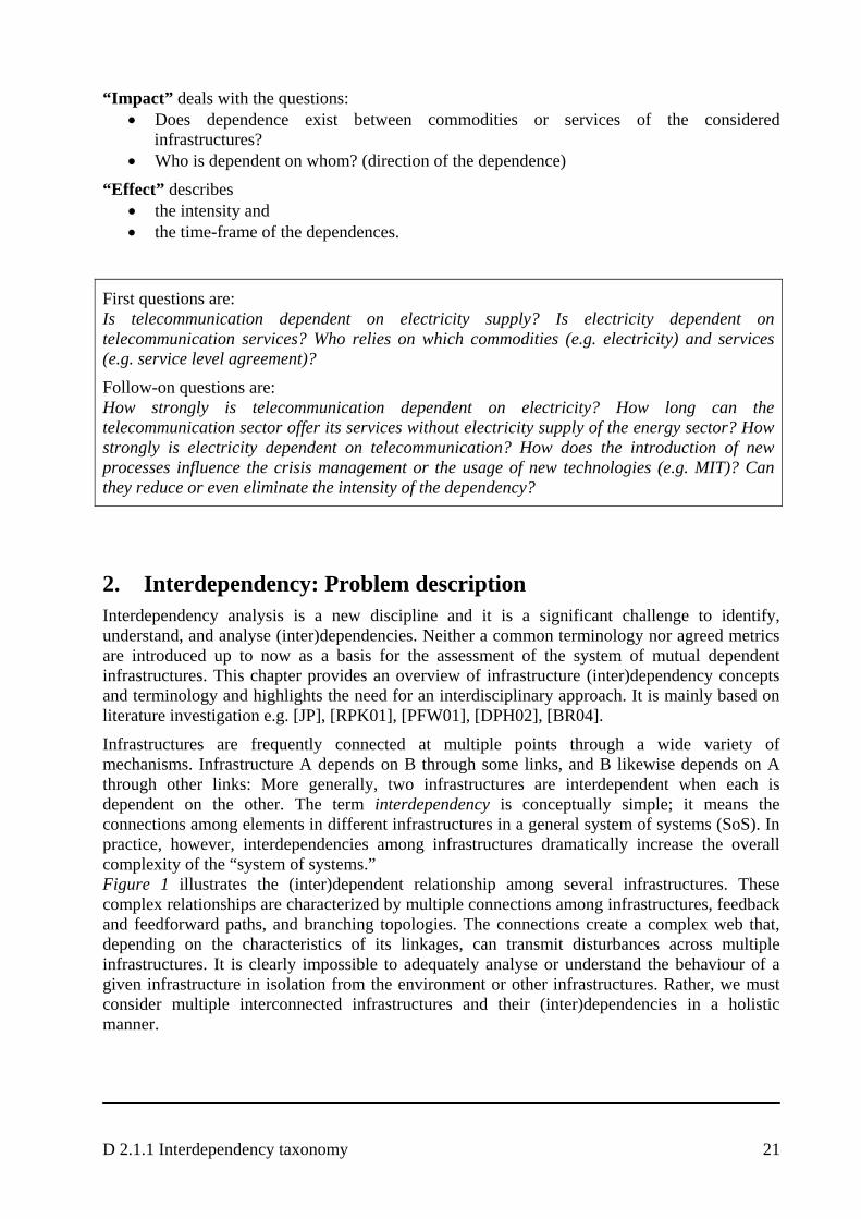
Infrastructures are frequently connected at multiple points through a wide variety of mechanisms. Infrastructure A depends on B through some links, and B likewise depends on A through other links: More generally, two infrastructures are interdependent when each is dependent on the other. The term interdependency is conceptually simple; it means the connections among elements in different infrastructures in a general system of systems (SoS). In practice, however, interdependencies among infrastructures dramatically increase the overall complexity of the “system of systems.” Figure 1 illustrates the (inter)dependent relationship among several infrastructures. These complex relationships are characterized by multiple connections among infrastructures, feedback and feedforward paths, and branching topologies. The connections create a complex web that, depending on the characteristics of its linkages, can transmit disturbances across multiple infrastructures. It is clearly impossible to adequately analyse or understand the behaviour of a given infrastructure in isolation from the environment or other infrastructures. Rather, we must consider multiple interconnected infrastructures and their (inter)dependencies in a holistic manner.
D 2.1.1 Interdependency taxonomy 22
Figure 1: Examples of infrastructure interdependencies
Traditionally, (inter)dependencies have been predominantly physical and geographic in nature. However, the proliferation of information technology, along with the increased use of automated monitoring and control systems and the increased reliance on the open marketplace for purchasing and selling infrastructure commodities and services, has increased the prevalence and importance of ICT-related (inter)dependencies. Infrastructure (inter)dependencies transcend individual infrastructure sectors and generally transcend individual public and private-sector companies. Further, they vary significantly in scale and complexity, ranging from local linkages (e.g., municipal water supply systems and local emergency services), to regional linkages (e.g., electric power distribution), to national linkages (e.g., power transmission) to international linkages (e.g., telecommunications, Internet). These scale and complexity differences create a variety of spatial, temporal, and system representation complexities that are not well understood or readily analysed.
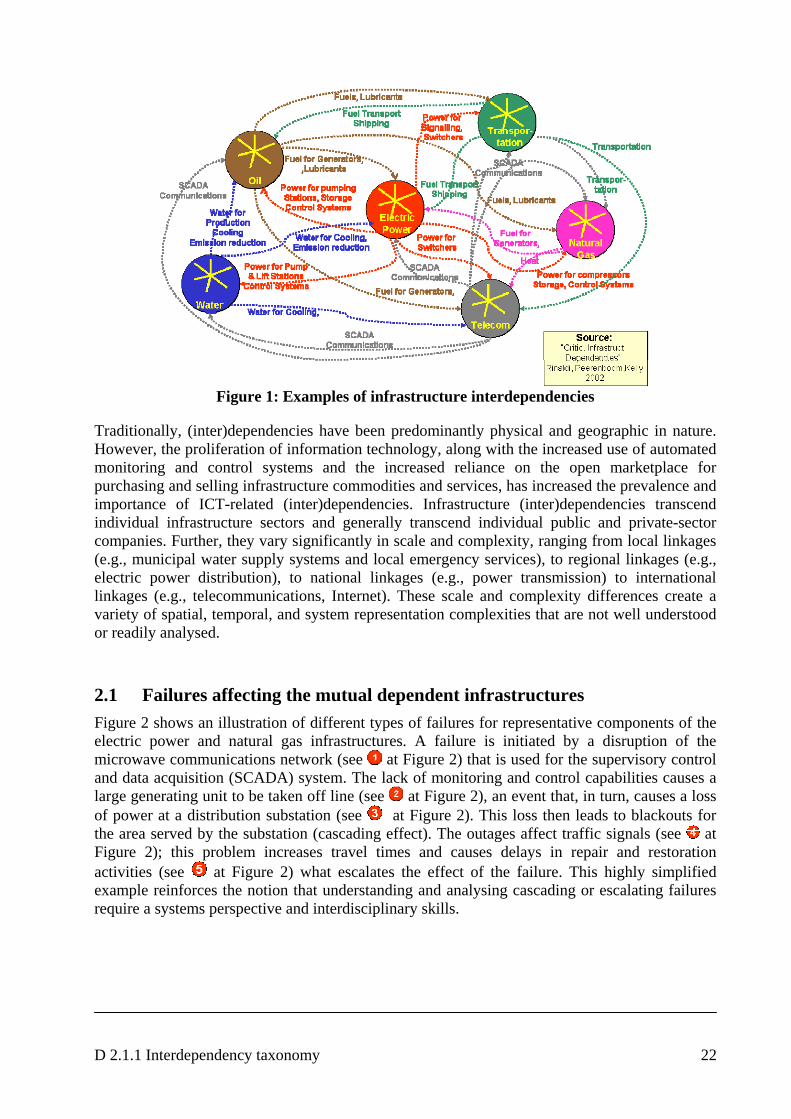
2.1 Failures affecting the mutual dependent infrastructures Figure 2 shows an illustration of different types of failures for representative components of the electric power and natural gas infrastructures. A failure is initiated by a disruption of the microwave communications network (see at Figure 2) that is used for the supervisory control and data acquisition (SCADA) system. The lack of monitoring and control capabilities causes a large generating unit to be taken off line (see at Figure 2), an event that, in turn, causes a loss of power at a distribution substation (see at Figure 2). This loss then leads to blackouts for the area served by the substation (cascading effect). The outages affect traffic signals (see at Figure 2); this problem increases travel times and causes delays in repair and restoration activities (see at Figure 2) what escalates the effect of the failure. This highly simplified example reinforces the notion that understanding and analysing cascading or escalating failures require a systems perspective and interdisciplinary skills.
D 2.1.1 Interdependency taxonomy 23
Figure 2: Examples of Cascading and Escalating Failures (source: [JP])
The state of operation of an infrastructure — which can range from normal operation to various levels of stress, disruption, or repair and restoration — must also be considered in examining interdependencies. Further, an understanding of backup systems or other mitigation mechanisms that reduce interdependency problems is necessary. 2.2 Threats
Failures of the electricity transmission network are relatively rare but their impact can cover wide areas. Distribution networks have a much bigger impact on the reliability and power quality for customers. In addition of the accidental physical damage of network components, the main vulnerabilities in electric power systems (EPSs) are connected with the ability to remotely access protection, control, automation and SCADA equipment. An intruder could for example access the substation SCADA system and operate circuit breakers in the substation that could affect the reliability of electricity supply or even cause big EPS failure. The current state of the resilience of the infrastructure can be characterised as follows:
• In general the system is planned and operated so that it stands incidents occurring with a certain level of probability. If one of these events takes place, the system is prepared to stand it and to isolate it automatically (in milliseconds). System and reserves are ready to restore the security level after an incident in seconds or in the worst case, in minutes.
• Electrical infrastructure is not planned and operated to support events more severe than the ones predefined by its probability. It is not normal that these incidents will occur, but if they will, than the system may react in any unpredicted way, even having a severe
D 2.1.1 Interdependency taxonomy 24
blackout. The probable reasons for severe incidents are extraordinary natural conditions (e.g. earthquakes or floods), malicious attacks and human errors.
• An incident in the transmission network will normally affect the whole EPS. Incidents in the distribution network are local. Due to the fact that there is less redundant equipment the probability to blackout a small area is higher.
• Electrical infrastructure is spread along the territory without the possibility to be hidden or to be watched in full extension. Attacks could cause blackouts with strong social impact and full media coverage. Those conditions could make malicious attack to the electric infrastructure attractive.
• Electrical infrastructure uses intensively communications to control the remote and unmanned substations and to improve the protections against normal faults of the network. Loss of communications may leave the system without control and without protection.
• Market agents clearing is based on the communications between the market operator and the different agents with operating capacity in this market [AWD06]. In some cases they may use Internet to receive the bids and communicate the results in “secure” ways. The system can suffer attacks by collapsing the communications with the servers or by modifying its databases. This will disrupt the economic part of the market, but it is unlikely it will affect the continuity of the electricity supply.
• In most of the high voltage lines, the ground cable supports a certain amount of fibre optics. The communications capacity of this fibre optics is shared by the electrical utility’s own purposes and by other communications operators that use the excess capacity. This means that an attack against a high Voltage tower may affect directly the electric and communications infrastructures.
The operation of a telecommunication system depends on reserve power in the case of electricity outage.
D 2.1.1 Interdependency taxonomy 25
3. Taxonomy: Dependency Concepts and Terminology
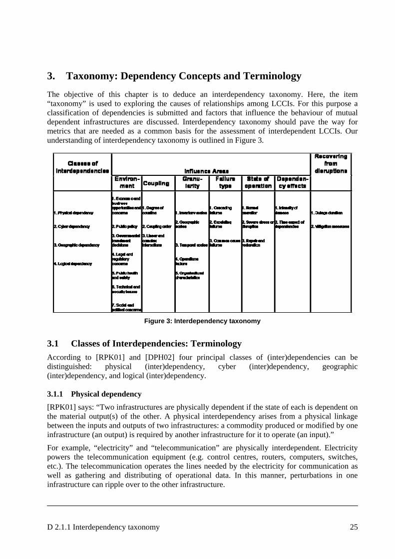
The objective of this chapter is to deduce an interdependency taxonomy. Here, the item “taxonomy” is used to exploring the causes of relationships among LCCIs. For this purpose a classification of dependencies is submitted and factors that influence the behaviour of mutual dependent infrastructures are discussed. Interdependency taxonomy should pave the way for metrics that are needed as a common basis for the assessment of interdependent LCCIs. Our understanding of interdependency taxonomy is outlined in Figure 3.
Figure 3: Interdependency taxonomy
3.1 Classes of Interdependencies: Terminology According to [RPK01] and [DPH02] four principal classes of (inter)dependencies can be distinguished: physical (inter)dependency, cyber (inter)dependency, geographic (inter)dependency, and logical (inter)dependency. 3.1.1 Physical dependency [RPK01] says: “Two infrastructures are physically dependent if the state of each is dependent on the material output(s) of the other. A physical interdependency arises from a physical linkage between the inputs and outputs of two infrastructures: a commodity produced or modified by one infrastructure (an output) is required by another infrastructure for it to operate (an input).”
For example, “electricity” and “telecommunication” are physically interdependent. Electricity powers the telecommunication equipment (e.g. control centres, routers, computers, switches, etc.). The telecommunication operates the lines needed by the electricity for communication as well as gathering and distributing of operational data. In this manner, perturbations in one infrastructure can ripple over to the other infrastructure.
D 2.1.1 Interdependency taxonomy 26
3.1.2 Cyber dependency [RPK01] says: “An infrastructure has a cyber dependency if its state depends on information transmitted through the information infrastructure.”
To a large degree, the reliable operation of modern infrastructures depends on computerised control systems (e.g., SCADA systems). Infrastructures require information transmitted and delivered by the information infrastructure. Consequently, the states of these infrastructures depend on outputs of the information infrastructure. Cyber dependencies connect infrastructures to one another via electronic, informational links; the outputs of the information infrastructure are inputs to the other infrastructure, and the “commodity” passed between the infrastructures is information. 3.1.3 Geographic dependency [RPK01] says: “Infrastructures are geographically dependent if a local environmental event can create state changes in all of them. A geographic dependency occurs when elements of multiple infrastructures are in close spatial proximity.”
For example, an explosion or fire could create correlated disturbances or changes in these geographically interdependent infrastructures. Such correlated changes are not due to physical or cyber connections between infrastructures; rather, they arise from the influence the event exerts on all the infrastructures simultaneously. An electrical line and a fibre-optic communications cable slung under a bridge connect (geographically) elements of the electric power, telecommunications, and transportation infrastructures. Because of the close spatial proximity, physical damage to the bridge could create correlated perturbations in the electric power, communications, and transportation infrastructures. 3.1.4 Logical dependency [RPK01] says: “Two infrastructures are logically dependent if the state of each depends on the state of the other via a mechanism that is not a physical, cyber, or geographic connection. The relationships on the international financial and commodity markets as well as the dependence on decisions of third parties (e.g. decisions of governments, international organisations) represent logical dependencies.”
For example, the genesis of the power crisis that emerged in California in late 2000 can be traced to the deregulation legislation that was passed in 1996 to open California’s electricity market to competition. Under that legislation, California’s investor-owned utilities were required to sell off their power-generating assets and purchase electricity on the open market. At the same time, however, the state experienced substantial load growth, a lack of investment in new generating capacity and transmission lines, reduced generation from aging power plants, high natural gas prices, transmission and environmental constraints, a drought in the Pacific Northwest, and a volatile spot market. This confluence of factors, plus the fact that utilities were not permitted to pass soaring wholesale power prices through to consumers, led to an unprecedented financial crisis that pushed one of the state’s largest utilities to bankruptcy and another to the brink of bankruptcy.
D 2.1.1 Interdependency taxonomy 27
3.2 Influence areas Metrics are needed as a common basis for the assessment of the system of mutual dependent infrastructures. But the behaviour of infrastructures is influenced by a broad range of interrelated factors and system conditions. According to [RPK01] the most important factors are: infrastructure environment, coupling and response behaviour of infrastructures, type of failures, infrastructure characteristics, states of operation. 3.2.1 Infrastructure environment The infrastructure environment1 is the framework in which the owners and operators establish goals and objectives, construct value systems for defining and viewing their businesses, model and analyse their operations, and make decisions that affect infrastructure architectures and operations. The operating state and condition of each infrastructure influence the environment, and the environment in turn exerts pressures on the individual infrastructures.
(1) Economic and business opportunities and concerns
According to [RPK01]: “Economic and business opportunities and concerns are major forces that shape the environment in which infrastructures evolve and operate. Opportunities and concerns lead to fundamental constraints on infrastructure operational characteristics and behaviour, owner-operator decisions, and, in some cases, infrastructure architectures and topologies.”
For example, water systems are generally owned and operated by municipal governments. The owners focus on service provision rather than on the profit concerns that motivate private-sector owners. Nevertheless, they still must address economic and business concerns, such as the cost of changes to their system architectures, maintenance, technology upgrades, and changing service demands from growing or contracting communities. Heavily regulated infrastructures are more constrained than unregulated, private-sector infrastructure firms. But regulated firms (e.g., some energy companies, and common carriers in the telecommunications sector) have the same motivations as unregulated firms but operate under tighter constraints. Within these constraints, profitability, economics, and business concerns are paramount. Information technology provided business with a powerful tool to increase operational efficiency, but it subsequently led to the proliferation of cyber dependencies (and new vulnerabilities) in most infrastructures. At the same time, the move toward deregulation of some sectors (such as energy) resulted in the reduction of excess capacity that had previously been mandated and had served as a shock absorber against system failures. Mergers further eliminated redundancy and overhead in infrastructure operations. The combination of these forces has created an environment in which infrastructures are much more dependent than in the past, have little or no cushion in case of failures. These environmental changes have critical implications for dependencies and their influences on infrastructure states and operating behaviours.
(2) Public policy
Public policy is another important environmental dimension. Examples of public policies include energy [EC03a], security [EC03b], [EU01], and economic policies [EC04c], [EP97], [EP01] that
1 The IRRIIS environment is described in [D1.2.1] “Scenario Analysis”.
D 2.1.1 Interdependency taxonomy 28
frame the response to disasters. Policies shape how industry and government operate, put bounds on the set of permissible operational states and characteristics, and influence the growth and structure of entire infrastructures.
(3) Government investment decisions
According to [RPK01]: “Government investment decisions are another major aspect of public policy that influences the infrastructure environment. Research, development, and acquisition decisions have had a wide-ranging influence on many aspects of our lives. The government played a major role in the creation of infrastructures by investing in specific technologies that were highly risky, expensive, and lacked near-term return on investment.” Examples of such investments are defence technologies, early research in computer networks and satellite communications.
(4) Legal and regulatory concerns
Legal and regulatory concerns form a special subset of public policy. Some examples are: • Sarbanes-Oxley Act and corresponding European regulations • Winter Report: “Report of the Level Group of Company Law Experts on a Modern
Regulatory Framework for Company Law in Europe” (4.11.2002, chairman: Jaap Winter) • German Corporate Governance Codex (14.11. 2002) • EU recommendations with respect to the independency of an accountant: “Independent
appearance”, “Independence in mind” • KonTraG2 (this law should improve the controlling and transparency in companies by
introducing of a risk management system with appropriate emergency plans) • Basel II: credit costs depend on risks of a company.
(5) Public health and safety
Some legal and regulatory concerns directly affect infrastructure operations. For example, environmental regulations that establish stringent power plant emissions standards to reduce air pollution and associated health-related problems directly influence decisions about system operation, new plant construction, reliance on SCADA and other electronic systems, and backup fuels. Each of these decisions affects the dependencies among the infrastructures. Identifying, understanding, and analyzing such dependencies are also of particular concern to the emergency services infrastructure, which is made up of fire, emergency medical, rescue, public health, law enforcement, and other services that support public health and safety at the local, national and international levels.
(6) Technical and security issues
According to [RPK01]: “Technical and security issues underlie all aspects of dependencies and the infrastructure environment. Technology is both an enabler of infrastructures and a primary source of dependencies. Advances in technology, such as computerisation and automation, have increased the efficiency, reliability, and service offerings of infrastructures. Infrastructure owners and operators must make business decisions about acquiring and inserting new technology to increase infrastructure functionality, add capability and capacity, or increase efficiency3. Technology is largely responsible for the tightly coupled, dependent infrastructures – extensive automation has dramatically increased cyber dependencies across all infrastructures and
2 Gesetz zur Kontrolle und Transparenz im Unternehmen (5.3.98 Deutscher Bundestag)
3 [D1.2.1] describes the technological frame of IRRIIS
D 2.1.1 Interdependency taxonomy 29
concurrently increased their complexity. However, tighter, more complex, and more extensive dependencies lead to increased risks and greater requirements for security.” Security weaknesses in one infrastructure increase the level of risk and decrease security in the other infrastructures that it supports4. Physical and cyber security are of paramount importance for infrastructure owners and operators. Physical security is a relatively mature field in which the threats and preventive measures are well understood. Cyber security, however, is relatively new and represents a particular challenge to dependent infrastructures. Given extensive cyber dependencies, careful attention to cyber security is essential for virtually all modern infrastructures. Technological advances created the information infrastructure and its associated cyber security problems. In fact, no technical solution is effective without equal consideration of human factors, security practices and policies, and training. Information technology is also a moving target. Just as information technology advances permit dramatic improvements in infrastructure service offerings, capabilities, and efficiency, the very same advances also create new security issues.
(7) Social and political concerns
According to [RPK01]: “Social and political concerns tie all environmental issues together. These concerns drive markets and public policies and regulations. They create the perception that laws or regulations are needed (or not), a service is needed (or not), certain types of behaviour are acceptable (or not), and certain protections are needed (or not). Less directly evident, yet critically important, are international social and political forces that shape the infrastructure environment. Many of today’s infrastructures are inherently international. For example, the telecommunications, banking and finance, and oil and gas infrastructures are truly global in scope. Political issues (e.g. abandoning nuclear energy), OPEC decisions, and instability in oil countries substantially affect the infrastructure environment5.“ 3.2.2 Coupling and response behaviour The characteristics of the couplings among infrastructures and their effects on infrastructure responses to perturbations have to be examined, because they provide indications whether the infrastructures are adaptive or inflexible when perturbed or stressed. Primary coupling characteristics are
• the degree of coupling (tightness or looseness), • the coupling order, and • the linearity or complexity of the interactions.
(1) Degree of coupling
Tight coupling refers to infrastructures that are highly dependent on one another. Disturbances in one infrastructure can be closely correlated to those in another infrastructure to which it is tightly coupled. Disturbances tend to propagate rapidly through and across tightly coupled infrastructures. Tight coupling is characterized by time-dependent processes that have little slack. A natural-gas-fired electrical generator and the gas supply pipeline form a tightly coupled pair. In particular, if the gas-fired generator has no local gas storage and cannot switch to an alternative fuel, the generator is very tightly coupled to the gas pipeline. Disturbances in the gas supply will have almost immediate effects on electrical generation.
4 see [D1.2.2] “Risk Analysis”
5 [D1.2.1] “Scenario Analysis” describes social and political aspects to be considered in IRRIIS
D 2.1.1 Interdependency taxonomy 30
Loose coupling, on the other hand, implies that the infrastructures are relatively independent of each other, and the state of one is only weakly correlated to the state of the other. Slack exists in the system, and the processes are not nearly as time dependent as in a tightly coupled system. For example, a coal-fired electrical generator and the diesel-powered railroad network that supplies its coal are weakly coupled. Coal-fired generators often have two or three months’ supply of coal stored locally. Short-term disturbances in the rail supply system rarely affect power generation, so the state of the electrical grid is thus weakly correlated to the state of the railroad through this specific dependency. In sum, tight and loose coupling refer to the relative degree of dependencies among the infrastructures.
(2) Coupling order
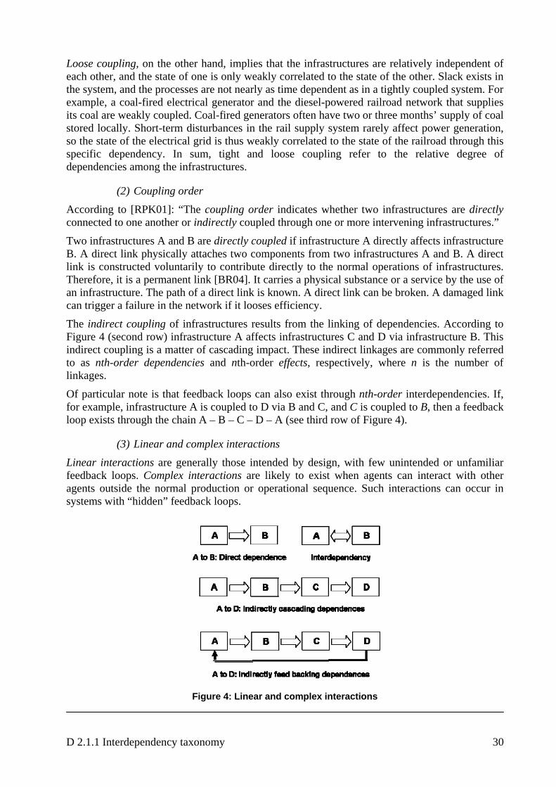
According to [RPK01]: “The coupling order indicates whether two infrastructures are directly connected to one another or indirectly coupled through one or more intervening infrastructures.”
Two infrastructures A and B are directly coupled if infrastructure A directly affects infrastructure B. A direct link physically attaches two components from two infrastructures A and B. A direct link is constructed voluntarily to contribute directly to the normal operations of infrastructures. Therefore, it is a permanent link [BR04]. It carries a physical substance or a service by the use of an infrastructure. The path of a direct link is known. A direct link can be broken. A damaged link can trigger a failure in the network if it looses efficiency.
The indirect coupling of infrastructures results from the linking of dependencies. According to Figure 4 (second row) infrastructure A affects infrastructures C and D via infrastructure B. This indirect coupling is a matter of cascading impact. These indirect linkages are commonly referred to as nth-order dependencies and nth-order effects, respectively, where n is the number of linkages.
Of particular note is that feedback loops can also exist through nth-order interdependencies. If, for example, infrastructure A is coupled to D via B and C, and C is coupled to B, then a feedback loop exists through the chain A – B – C – D – A (see third row of Figure 4).
(3) Linear and complex interactions
Linear interactions are generally those intended by design, with few unintended or unfamiliar feedback loops. Complex interactions are likely to exist when agents can interact with other agents outside the normal production or operational sequence. Such interactions can occur in systems with “hidden” feedback loops.
Figure 4: Linear and complex interactions
D 2.1.1 Interdependency taxonomy 31
Finally, the characteristics of the agents comprising the infrastructures and their dependencies influence whether a given infrastructure is adaptive or inflexible when stressed or perturbed. Numerous factors contribute to adaptability, e.g.
• redundancy • contingency plans and crisis management • backup systems • training and educational programs for operational personnel • and last but not least skilled personal.
Other factors may render infrastructures inflexible, such as • restrictive legal and regulatory regimes • health and safety standards • social concerns • organisational policies • fixed network topologies • high cost of providing extensive backups and workarounds.
Critical infrastructures comprising flexible agents are rather able to respond well to disturbances and continue to provide essential goods and services than is an inflexible system that is incapable of learning from past experiences. 3.2.3 Granularity: Infrastructure characteristics
Infrastructures have key characteristics like inventory scales, geographic scales, temporal scales, operational factors, and organisational characteristics.
(1) Inventory scales
According to [RPK01]: “Spatial scales can vary widely in infrastructure analyses. Spatial scales range from individual parts to the system of systems composed of mutual dependent infrastructures and the environment. So, a hierarchy of elements can be defined:
• Part: smallest component of a system that can be identified in an analysis. • Unit: a functionally related collection of parts (e.g., a steam generator). • Subsystem: an array of units (e.g., a secondary cooling system). • System: a grouping of subsystems (e.g., a nuclear power plant). • Infrastructure: a complete collection of like systems (e.g., the electric power
infrastructure). • Interdependent Infrastructures: the interconnected web of infrastructures and
environment.”
(2) Geographic scales
In general infrastructures span physical spaces ranging in scale from local, regional, and national to international levels. The particular scale of interest is largely a function of the objectives of the analysis. Deliberations on national energy policies may require analyses at the national and international levels, whereas an analysis of the failure of a single electricity generator might require studies at the system level and below. These granularity considerations lead to trade-offs in model fidelity and database/computational requirements: a high level of detail implies more data on the infrastructures, their components, and interdependencies, as well as more intensive computational requirements.
D 2.1.1 Interdependency taxonomy 32
(3) Temporal scales
According to [RPK01]: “Infrastructure dynamics span a vast temporal range. Relevant time scales of interest vary from milliseconds (e.g., power system operation) to hours (e.g., transportation system operations) to years (e.g., infrastructure upgrades and new capacity). Time scales have substantial implications for models and simulations. The tightness or looseness of a specific dependency is somewhat related to its temporal dynamics and may determine whether that dependency is pertinent to an analysis.
For example, in an examination of the propagation of sudden failure in an electrical power grid, fast processes, such as some cyber dependencies (with millisecond to hour dynamics), might be crucial to the analysis, particularly if SCADA systems figure prominently. Slower dynamics, however, such as the enactment of new energy regulations (years), or the construction of a new power plant (years to a decade or more), would not be issues if the analysis only examined a period of several days.”
(4) Operational factors
According to [RPK01]: “Operational factors influence how infrastructures react when stressed or perturbed. These factors are closely related to security and risk and include operating procedures; operator education and training; backups and redundant systems; emergency workarounds; contingency plans; and security policies, including implementation and enforcement. All of these factors are difficult to model.”
For example, the presence of inadequately trained computer network administrators at an electric power utility would lead to a decrease in the overall cyber security of the SCADA systems and consequently raise the level of risk in other infrastructures dependent on the utility’s electric power.
(5) Organisational characteristics
According to [RPK01]: “Organizational considerations are important determinants of infrastructure behaviour. Aspects like globalisation, international ownership, regulation, government versus private ownership, corporate policies and motivations can be key factors in determining the operational characteristics of infrastructures, with important security and risk implications. As a result, a detailed scenario description of infrastructures and their dependencies should first evaluate the importance of these factors and determine whether they merit inclusion in a more detailed analysis.” 3.2.4 Failure types According to [RPK01]: “Dependencies increase the risk of failures or disruptions in multiple infrastructures, as the big blackouts in recent years have demonstrated. The subtle feedback loops and complex topologies created by dependencies can initiate and propagate disturbances in a variety of ways that are unusual and difficult to foresee. We classify dependency-related disruptions or outages as cascading, escalating, or common cause.
(1) Cascading failure
A cascading failure occurs when a disruption in one infrastructure causes the failure of a component in a second infrastructure, which subsequently causes a disruption in the second infrastructure. For example, the disruption of a distribution network within the electricity infrastructure can result in a failure (disruption) of the regional telecommunication network.

D 2.1.1 Interdependency taxonomy 33
(2) Escalating failure
An escalating failure occurs when an existing disruption in one infrastructure exacerbates an independent disruption of a second infrastructure, generally in the form of increasing the severity or the time for recovery or restoration of the second failure. For example, a disruption in a telecommunications network may escalate because of a simultaneous or subsequent disruption in a road transportation network, which in turn could delay the arrival of repair crews and replacement equipment.
(3) Common cause failure
A common cause failure occurs when two or more infrastructure networks are disrupted at the same time due to common cause (e.g., a natural disaster, such as an earthquake or flood, or a man-made disaster, such as a terrorist act).
For example, telecommunications cables and electric power lines often follow railroad rights-of-way, creating a geographic interdependency among the transportation, telecommunications, and electric power infrastructures. Consequently, a train derailment that damages the tracks could also disrupt communications cables and power lines that are located within the same corridor.” 3.2.5 State of operation
(1) Normal operation
According to [RPK01]: “The state of operation of an infrastructure can exhibit different behaviours during normal operating conditions (which can vary from peak to off-peak conditions), during times of severe stress or disruption, or during times when repair and restoration activities are under way. The state of operation of a unit, subsystem, or system at the time of a failure will affect the extent and duration of any disruption or degradation in the services of an infrastructure.
(2) Severe stress or disruption
For example, events that occur at times of peak electric power demand, when telephone usage is heavy, or during periods of traffic congestion, will have different effects than similar events during non-peak times.
Conceptually, the state of operation of an infrastructure can range from optimal design operation to complete failure with a total loss of service to all users. Under certain conditions, an infrastructure can operate below the optimal design state and still provide what the user perceives as full service.
(3) Repair and restoration
For example, generating units in the electric power infrastructure can be out of service for maintenance or repair with no limitation in service to users as long as the condition does not occur during the peak usage period when reserve margins are critically low.
To fully understand and analyse infrastructure dependencies, it is necessary to determine, for each infrastructure, which other infrastructures it depends on continuously or nearly continuously for normal operations, which other infrastructures it depends on during times of high stress or disruption, and which it depends on to restore service following the failure of a component or components that disrupt the infrastructure. The normal operation of an infrastructure and the repair of a disrupted infrastructure generally involve multiple functions (activities, processes, or operations). Some of the functions occur sequentially in time, whereas
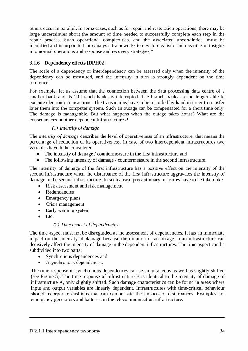
D 2.1.1 Interdependency taxonomy 34
others occur in parallel. In some cases, such as for repair and restoration operations, there may be large uncertainties about the amount of time needed to successfully complete each step in the repair process. Such operational complexities, and the associated uncertainties, must be identified and incorporated into analysis frameworks to develop realistic and meaningful insights into normal operations and response and recovery strategies.” 3.2.6 Dependency effects [DPH02] The scale of a dependency or interdependency can be assessed only when the intensity of the dependency can be measured, and the intensity in turn is strongly dependent on the time reference.
For example, let us assume that the connection between the data processing data centre of a smaller bank and its 20 branch banks is interrupted. The branch banks are no longer able to execute electronic transactions. The transactions have to be recorded by hand in order to transfer later them into the computer system. Such an outage can be compensated for a short time only. The damage is manageable. But what happens when the outage takes hours? What are the consequences in other dependent infrastructures?
(1) Intensity of damage The intensity of damage describes the level of operativeness of an infrastructure, that means the percentage of reduction of its operativeness. In case of two interdependent infrastructures two variables have to be considered:
• The intensity of damage / countermeasure in the first infrastructure and • The following intensity of damage / countermeasure in the second infrastructure.
The intensity of damage of the first infrastructure has a positive effect on the intensity of the second infrastructure when the disturbance of the first infrastructure aggravates the intensity of damage in the second infrastructure. In such a case precautionary measures have to be taken like
• Risk assessment and risk management • Redundancies • Emergency plans • Crisis management • Early warning system • Etc.
(2) Time aspect of dependencies
The time aspect must not be disregarded at the assessment of dependencies. It has an immediate impact on the intensity of damage because the duration of an outage in an infrastructure can decisively affect the intensity of damage in the dependent infrastructures. The time aspect can be subdivided into two parts:
• Synchronous dependences and • Asynchronous dependences.
The time response of synchronous dependences can be simultaneous as well as slightly shifted (see Figure 5). The time response of infrastructure B is identical to the intensity of damage of infrastructure A, only slightly shifted. Such damage characteristics can be found in areas where input and output variables are linearly dependent. Infrastructures with time-critical behaviour should incorporate cushions that can compensate the impacts of disturbances. Examples are emergency generators and batteries in the telecommunication infrastructure.
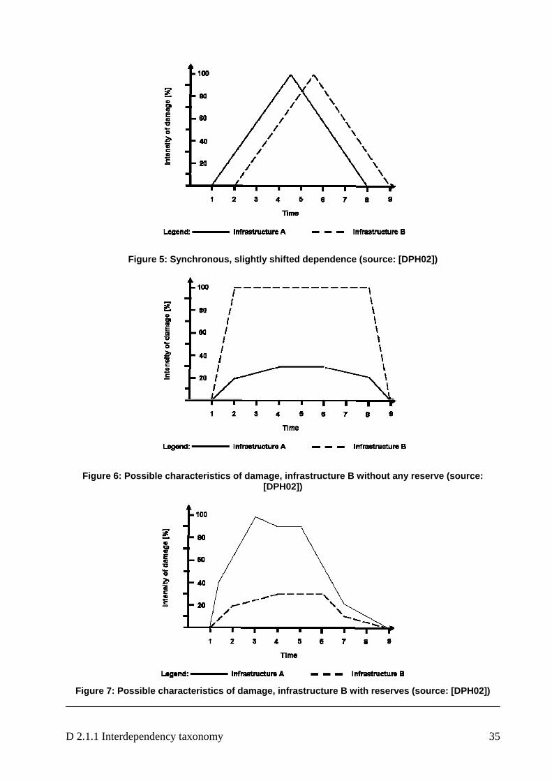
D 2.1.1 Interdependency taxonomy 35
Figure 5: Synchronous, slightly shifted dependence (source: [DPH02])
Figure 6: Possible characteristics of damage, infrastructure B without any reserve (source: [DPH02])
Figure 7: Possible characteristics of damage, infrastructure B with reserves (source: [DPH02])
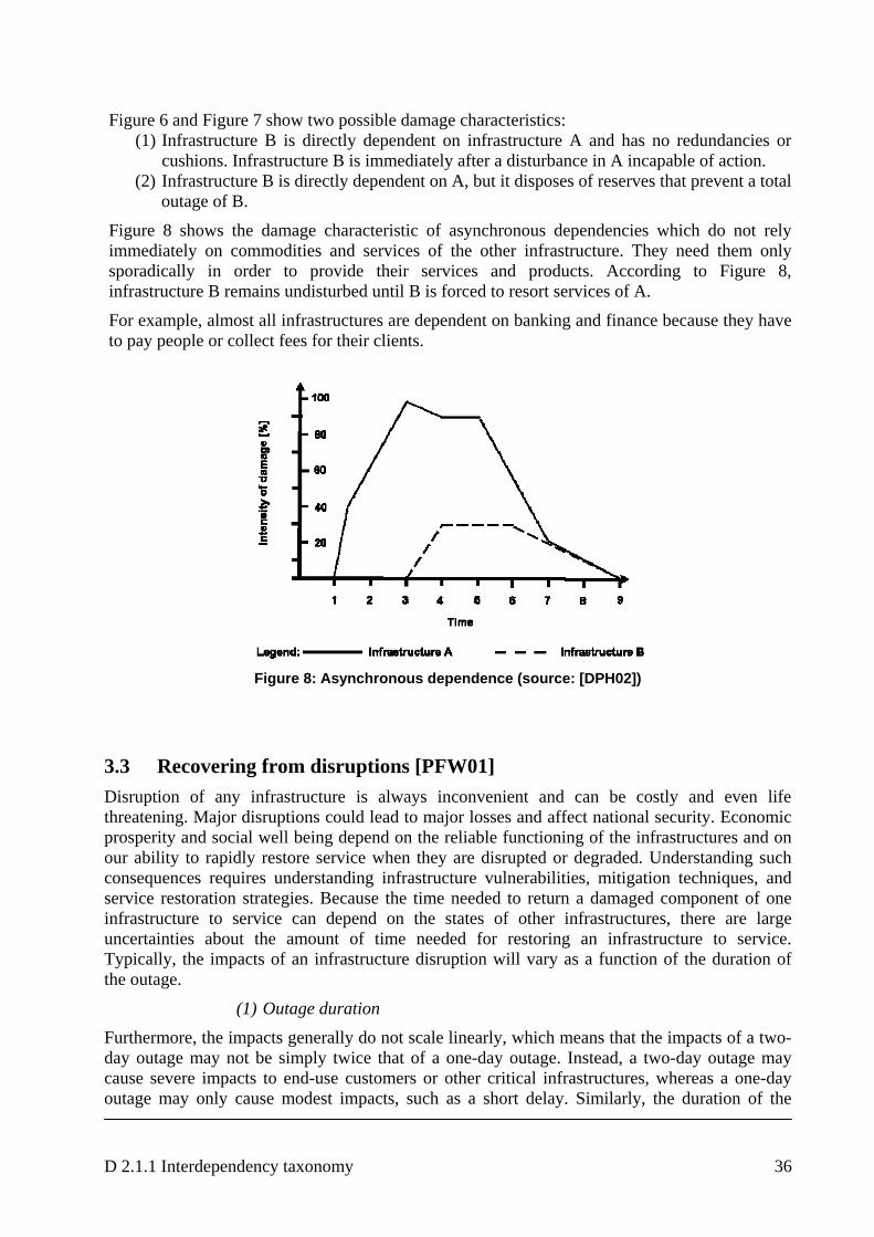
D 2.1.1 Interdependency taxonomy 36
Figure 6 and Figure 7 show two possible damage characteristics:
(1) Infrastructure B is directly dependent on infrastructure A and has no redundancies or cushions. Infrastructure B is immediately after a disturbance in A incapable of action.
(2) Infrastructure B is directly dependent on A, but it disposes of reserves that prevent a total outage of B.
Figure 8 shows the damage characteristic of asynchronous dependencies which do not rely immediately on commodities and services of the other infrastructure. They need them only sporadically in order to provide their services and products. According to Figure 8, infrastructure B remains undisturbed until B is forced to resort services of A.
For example, almost all infrastructures are dependent on banking and finance because they have to pay people or collect fees for their clients.
Figure 8: Asynchronous dependence (source: [DPH02])
3.3 Recovering from disruptions [PFW01] Disruption of any infrastructure is always inconvenient and can be costly and even life threatening. Major disruptions could lead to major losses and affect national security. Economic prosperity and social well being depend on the reliable functioning of the infrastructures and on our ability to rapidly restore service when they are disrupted or degraded. Understanding such consequences requires understanding infrastructure vulnerabilities, mitigation techniques, and service restoration strategies. Because the time needed to return a damaged component of one infrastructure to service can depend on the states of other infrastructures, there are large uncertainties about the amount of time needed for restoring an infrastructure to service. Typically, the impacts of an infrastructure disruption will vary as a function of the duration of the outage.
(1) Outage duration
Furthermore, the impacts generally do not scale linearly, which means that the impacts of a two-day outage may not be simply twice that of a one-day outage. Instead, a two-day outage may cause severe impacts to end-use customers or other critical infrastructures, whereas a one-day outage may only cause modest impacts, such as a short delay. Similarly, the duration of the
D 2.1.1 Interdependency taxonomy 37
outage can not be predicted with certainty. Rather the duration of an outage is uncertain and can be represented as a probability distribution. Tools are needed that estimate the time needed for activities that have to be completed to restore
(2) Mitigation measures
For example, if a o impact from an infrastructure failure of 4 hours or
ents needed to restore service by
•
ecovery, and restoration processes.
Var
everity
e
Better information about outage duration times can assist infrastructure operators in determining
4. Infrastructures as Complex Adaptive Systems es have one property in
a given infrastructure component, a specific infrastructure system, or a dependent set of infrastructures to an operational state. The outage duration times estimated assist decision makers in determining appropriate mitigation measures.
decision maker will face nless and is highly confident that infrastructure failures can be restored to service within that duration, then no mitigation action may be justified. However, if a big probability exists that the infrastructure failure may last longer than the 4 hours, then mitigation measures may be appropriate. The benefits of such a tool include the following:
• Creates a representative model of the activities and evrepairing a damaged component to service or creating a workaround Specifies relationships among events, activities, and states of service
• Characterises completion times for required activities • Considers the interdependencies as well as the repair, r
iables that can impact restoration times include: • Time of day • Day of week • Weather • Incident s• Terrain / location • Outside interferenc• Critical customers • System connectivity• Etc.
their vulnerability to infrastructure failures. Decision makers can better decide on potential mitigation measures such as redundant infrastructure connections or alternative fuel sources. Infrastructure operators can better understand bottlenecks in the restoration process and take action to potentially lessen outage duration times. Bottlenecks such as staff and spare part placement can be optimised throughout their service territory.
According to [RPK01]: “All of the aforementioned critical infrastructurcommon—they are all complex collections of interacting components in which change often occurs as a result of learning processes; that is, they are complex adaptive systems (CASs): Each component of an infrastructure constitutes a small part of the intricate web that forms the overall infrastructure. Many components are individually capable of learning from past experiences and adapting to future expectations, such as operating personnel who try to improve their performance and real-time computer systems that adjust electric generator outputs to meet varying power loads. From a CAS perspective, infrastructures are more than just an aggregation of their components. Typically, as large sets of components are brought together and interact with one another, synergies emerge. One example may be the emergence of reliable electric
D 2.1.1 Interdependency taxonomy 38
power delivery from a collection of well-placed electric generators, transformers, transmission lines, and related components. Simply aggregating the components in an ad hoc fashion will not ensure reliable electricity supplies. Only the careful creation of an intricate set of services will yield a system that reliably and continuously supplies electricity. This additional complexity exhibited by a system as a whole, beyond the simple sum of its parts, is called emergent behaviour and is a hallmark of CASs [RPK01]. Complex adaptive systems do not require strong central control for emergent behaviours to arise. One effective way to investigate CASs is to view them as populations of interacting agents. An agent is an entity with a location, capabilities, and memory. Although the term agent is frequently used when discussing specific modelling techniques, we use it here in the abstract to describe entities with general characteristics. The entity’s location defines where it is in a physical space, such as a geographic region, or an abstract space, such as the Internet, or both. The entity’s capabilities define what it can do from its location, such as an electric generator increasing its output or an oil pipeline reducing its pumping rate. The entity’s memory defines what it has experienced, such as overuse or aging. Memory is often expressed in the form of agent state variables. Most infrastructure components have a location and capabilities and are influenced by past experiences. Thus, most infrastructure components can be viewed as agents.”
Example: Consider a transmission grid. Its location can be expressed physically as a set of latitudes and longitudes and abstractly as a specific stage in the delivery process. The capability of the grid includes not only its ability to transmit electricity, but also the ways in which it responds to emergencies. The memory of the grid may include the current and past flow rates, capacities, operating status of its generators, and so forth. Agents communicate with one another as they operate in a particular environment. Each agent receives inputs from other agents and sends outputs to them. These “inputs” and “outputs” need not be resources used in, or products made by, an infrastructure or process. Metrics that describe the state of an agent can also be viewed as outputs that other agents can sense (use as input) and act upon. The inputs to a transmission grid include the current demand for electricity, whereas its outputs include the flow of electricity to external clients and price information.
D 2.1.1 Interdependency taxonomy 39
5. The need for interdisciplinary skills [JP] Chapter 3.2 delineates the many influence areas and complexities associated with understanding and analysing infrastructure interdependencies. The key point is that interdisciplinary expertise and research are needed to address these dimensions. For example
• engineers (e.g., civil, electrical, industrial, mechanical, systems) are needed to understand the technological underpinnings of the infrastructures, as well as the complex physical architectures and dynamic feedback mechanisms that govern their operation and response (e.g., response to stresses and disruptions).
• Computer scientists, information technology specialists, and network/telecommunications experts are needed to understand the electronic and informational (cyber) linkages among the infrastructures.
• Information security and information assurance professionals are needed to ensure cybersecurity.
• Economists are needed to understand the myriad of marketplace and financial considerations that shape the business environment for public and private-sector infrastructure owners and operators.
• Social scientists are needed to understand the behaviours of infrastructure service providers, brokers, consumers, and other organizational entities competing in the new economy.
• Lawyers, regulatory analysts, and public policy experts are needed to understand the legal, regulatory, and policy environment within which the infrastructures operate.
• Security and risk management experts are needed to perform vulnerability assessments (physical and cyber) and develop strategies to protect against, mitigate the effects of, respond to, and recover from infrastructure disruptions.
• Decision analysts are needed to help owners and operators make defensible, cost-effective infrastructure operation and management decisions.
• And software engineers, along with appropriate domain experts, are needed to develop modelling and simulation tools to assess the technical, economic, and national security implications of technology and policy decisions designed to ensure the reliability and security of these interdependent infrastructures.
It also will necessitate focused education and awareness efforts to prepare professionals to understand fundamental interdependency concepts and issues and the “system of systems” paradigm.
D 2.1.1 Interdependency taxonomy 40
6. IRRIIS: area of interest and constraints
Vulnerabilities in the critical sectors / services “electricity” and “telecommunication / Internet” are believed to be on the rise due to increasingly ICT-based dependencies and even interdependencies. The aforementioned critical infrastructures are either built upon, or monitored and controlled by vulnerable ICT-systems. In order to increase the protection of “electricity” and “telecommunication / Internet”, this “cyber”-infrastructure will be the focal point of the IRRIIS project approach.
This part is essential for the continuity of these critical services. It concerns the protection of the information layer underlying many of our critical infrastructures (CIs) and is therefore an issue of high relevance to many stakeholders / actors.
IRRIIS aims to enhance substantially the dependability of LCCIs by introducing appropriate Middleware Improved Technology (MIT). MIT facilitates the communication between providers of different sectors as well as different providers within the same sector. MIT is aiming at mitigating negative effects resulting from mutual dependencies. It has to be noted, that within IRRIIS the actual objects of protection interests are not static infrastructures as such, but rather concern the services, the physical and electronic (information-) flows, and the core values that are delivered by the ICT-based LCCIs.
In this context IRRIIS confines to:
• Technical perspective: IRRIIS develops technologies to foster information exchange and to mitigate negative effects resulting from mutual dependencies and interdependencies between different infrastructures.
• Management perspective: The protection of critical infrastructures is seen as an issue of “service continuity” and covers technical level including organisational and human factors.
• Dependency perspective: Vulnerabilities based upon ICT-related dependencies and even interdependencies between “electricity” and “telecommunication / Internet” are the focus of IRRIIS.
• Geographical perspective: IRRIIS considers EU but case studies may be limited to single countries or trans-border regions depending on the availability of data.
• Time perspective: IRRIIS state-of-the-art solutions consider the time span from today to 2015.
6.1 Electricity network [D1.2.1]
The electricity infrastructure consists of electrical power generation, bulk transmission of electricity from power stations to load centres and its distribution to customers. In order to perform their functions and to attain suitable effectiveness, all power stations, substations, power lines, the related control centres and other components are interconnected forming an electrical power system (EPS). In the most general terms, an EPS can be partitioned into generating stations, transmission and distribution networks and consumers (see Figure 9).
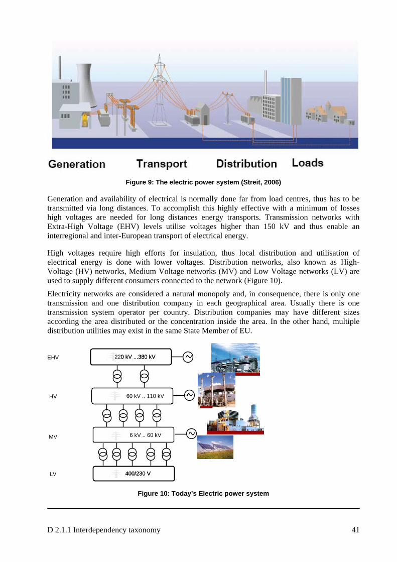
D 2.1.1 Interdependency taxonomy 41
Figure 9: The electric power system (Streit, 2006)
Generation and availability of electrical is normally done far from load centres, thus has to be transmitted via long distances. To accomplish this highly effective with a minimum of losses high voltages are needed for long distances energy transports. Transmission networks with Extra-High Voltage (EHV) levels utilise voltages higher than 150 kV and thus enable an interregional and inter-European transport of electrical energy.
High voltages require high efforts for insulation, thus local distribution and utilisation of electrical energy is done with lower voltages. Distribution networks, also known as High-Voltage (HV) networks, Medium Voltage networks (MV) and Low Voltage networks (LV) are used to supply different consumers connected to the network (Figure 10).
Electricity networks are considered a natural monopoly and, in consequence, there is only one transmission and one distribution company in each geographical area. Usually there is one transmission system operator per country. Distribution companies may have different sizes according the area distributed or the concentration inside the area. In the other hand, multiple distribution utilities may exist in the same State Member of EU.
60 kV .. 110 kV
400/230 V400/230 V
220 kV ...380 kV220 kV ...380 kV
6 kV .. 60 kV
LV
MV
HV
EHV
Figure 10: Today’s Electric power system
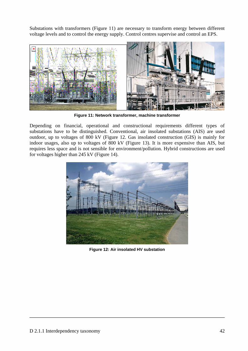
D 2.1.1 Interdependency taxonomy 42
Substations with transformers (Figure 11) are necessary to transform energy between different voltage levels and to control the energy supply. Control centres supervise and control an EPS.
Figure 11: Network transformer, machine transformer
Depending on financial, operational and constructional requirements different types of substations have to be distinguished. Conventional, air insolated substations (AIS) are used outdoor, up to voltages of 800 kV (Figure 12. Gas insolated construction (GIS) is mainly for indoor usages, also up to voltages of 800 kV (Figure 13). It is more expensive than AIS, but requires less space and is not sensible for environment/pollution. Hybrid constructions are used for voltages higher than 245 kV (Figure 14).
Figure 12: Air insolated HV substation
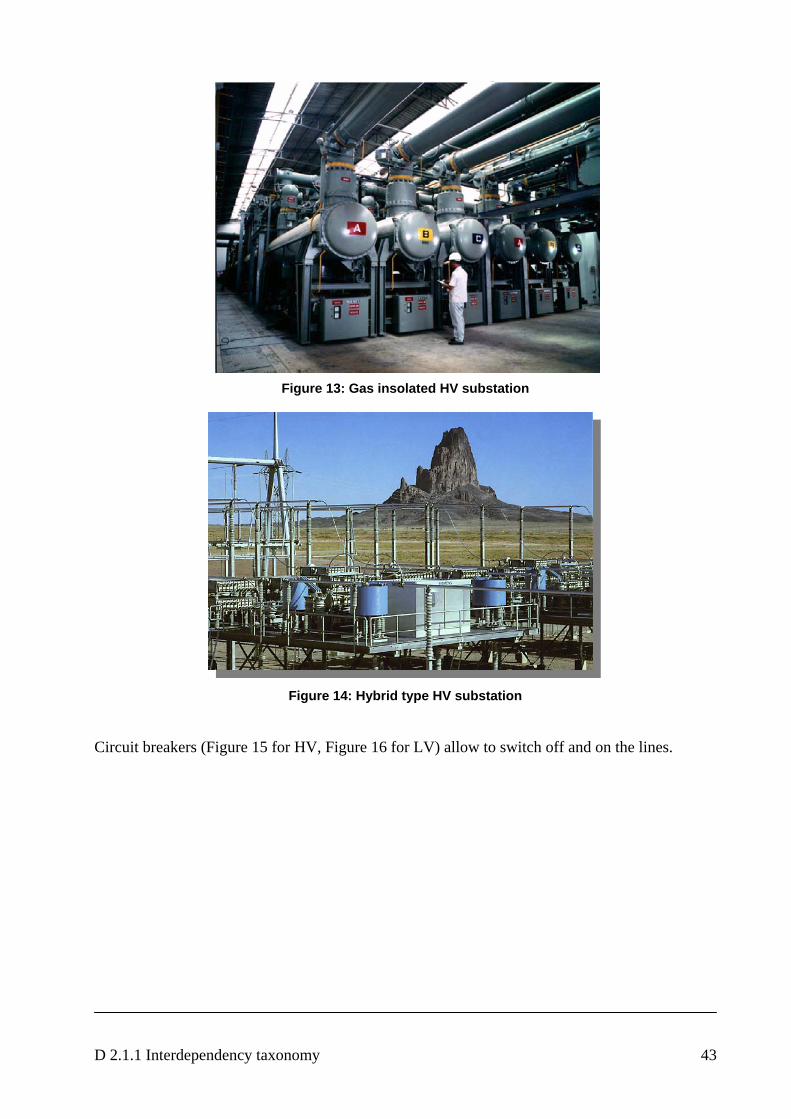
D 2.1.1 Interdependency taxonomy 43
Figure 13: Gas insolated HV substation
Figure 14: Hybrid type HV substation
Circuit breakers (Figure 15 for HV, Figure 16 for LV) allow to switch off and on the lines.
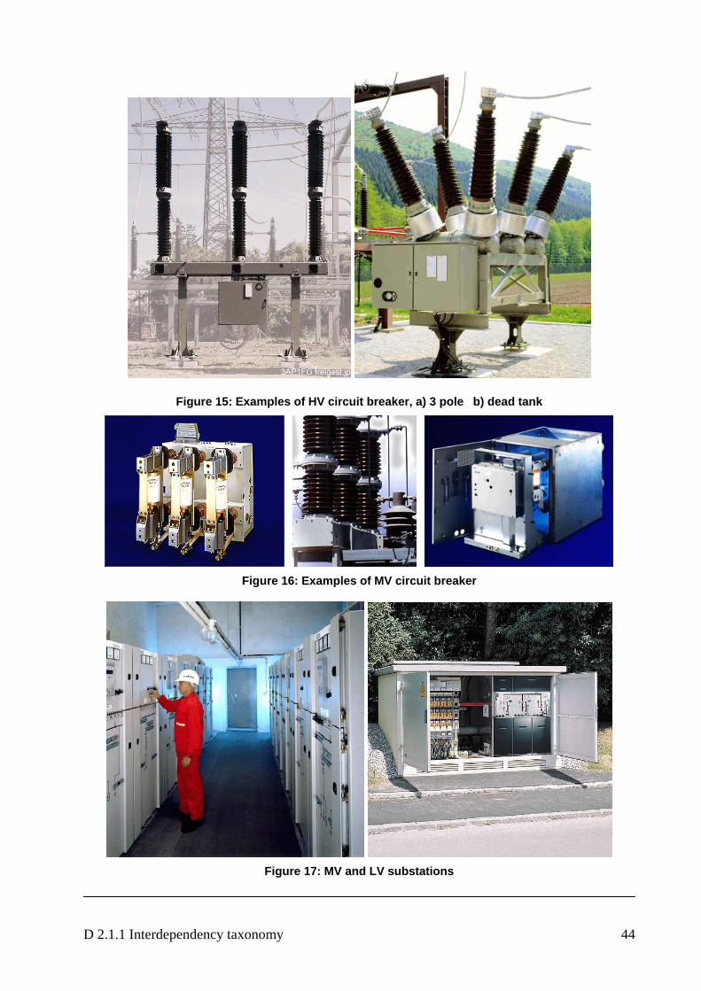
D 2.1.1 Interdependency taxonomy 44
Figure 15: Examples of HV circuit breaker, a) 3 pole b) dead tank
Figure 16: Examples of MV circuit breaker
Figure 17: MV and LV substations
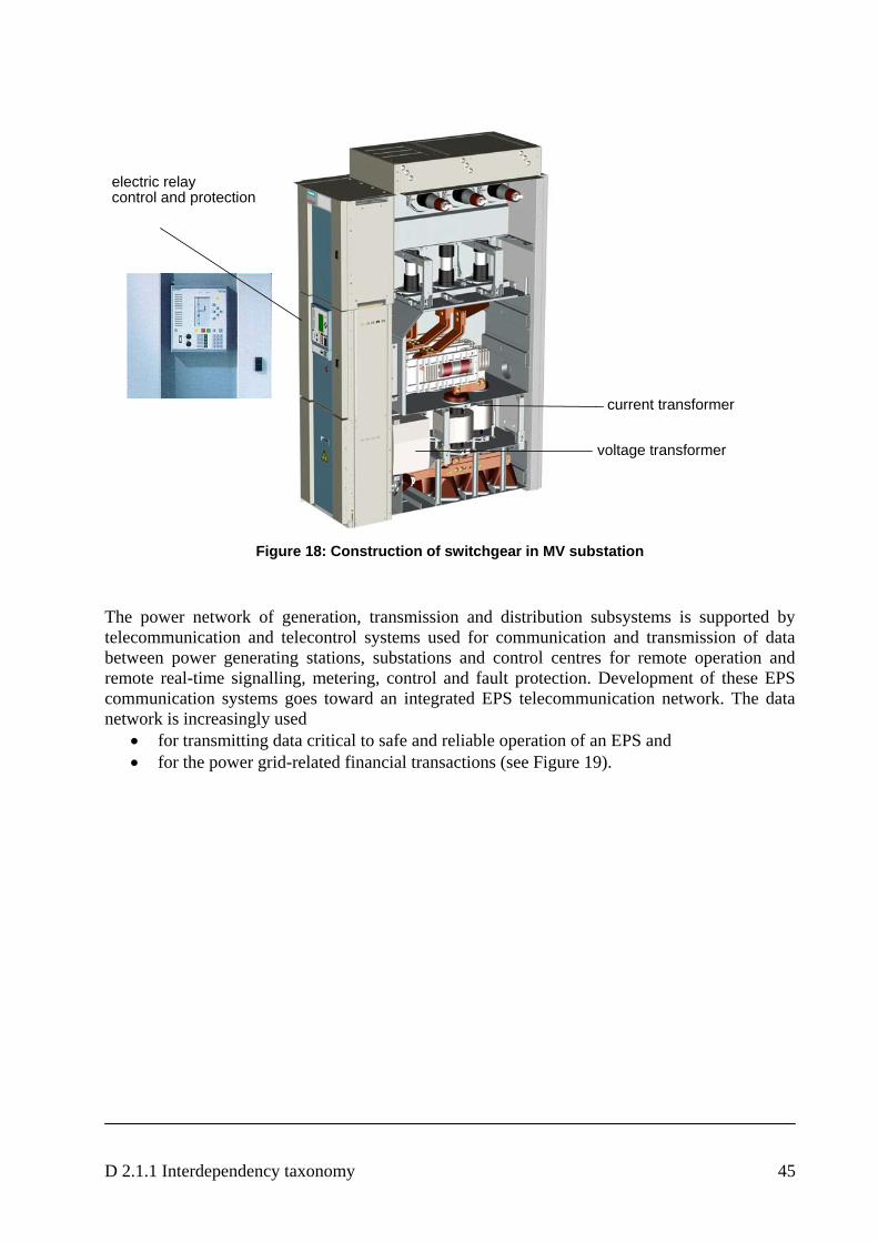
D 2.1.1 Interdependency taxonomy 45
current transformer
voltage transformer
electric relaycontrol and protection
Figure 18: Construction of switchgear in MV substation
The power network of generation, transmission and distribution subsystems is supported by telecommunication and telecontrol systems used for communication and transmission of data between power generating stations, substations and control centres for remote operation and remote real-time signalling, metering, control and fault protection. Development of these EPS communication systems goes toward an integrated EPS telecommunication network. The data network is increasingly used
• for transmitting data critical to safe and reliable operation of an EPS and • for the power grid-related financial transactions (see Figure 19).

D 2.1.1 Interdependency taxonomy 46
Figure 19: ICT dependency of electricity (Streit, 2006)
Although computerisation of EPSs progresses quickly the full automatic control of an EPS in normal and emergency states is currently not applied and realisation of such an idea seems to be rather distant especially for safety and reliability reasons. Control function is performed from the area control centre. The area control centre receives information and controls several substations. A SCADA (Supervisory Control and Data Acquisition) system does this control function and collects in real time (at few seconds’ time interval) all the information available. Figure 20 shows the ICT dependence of SCADA system.
Figure 20: ICT dependence of SCADA system
D 2.1.1 Interdependency taxonomy 47
This information is used for drawing a complete picture of the supervised network, and it allows the operator to modify the topology of the electrical network by acting over the breakers and other switchgear equipment. A remote terminal unit (RTU) collects the information inside each substation. After a first elemental processing of the information, the RTU transmits it at request to the SCADA server of the area control centre. Communication system connects the control centre with the equipment installed in the field. Without these communications the electrical infrastructure will be without control.
6.2 Interdependencies between electricity and telecommunications
The only objective of the electric infrastructure is to provide end-users with the requested amount of electrical power and energy against minimum costs and a sufficient quality of service. The quality is measured as the service continuity and the wave quality (frequency, voltage). In Europe, the electrical infrastructure was unbundled in different activities, which have the dependences between the different providers within the same sector as well as between the electricity and telecommunication sectors as described in the following.
Generation: There are many generating utilities that offer their generation in the market. Those companies coexist with newly arising Independent Power Producers (IPP) which produces energy using renewable resources (wind-mills, water, geothermic…) or cogeneration.
Transmission System: ‘transmission' means the transport of electricity on the extra high-voltage and high-voltage interconnected system with a view to its delivery to final customers or to distributors, but not including supply;There are services of transmission network operation and of transmission system operation. A TSO (transmission system operator) is a natural or legal person responsible for operating, ensuring the maintenance of and, if necessary, developing the transmission system in a given area and, where applicable, its interconnections with other systems, and for ensuring the long term ability of the system to meet reasonable demands for the transmission of electricity Each TSO shall be responsible for [EU03]:
a) ensuring the long-term ability of the system to meet reasonable demands for the transmission of electricity;
b) contributing to security of supply through adequate transmission capacity and system reliability;
c) managing energy flows on the system, taking into account exchanges with other interconnected systems. To that end, the transmission system operator shall be responsible for ensuring a secure, reliable and efficient electricity system and, in that context, for ensuring the availability of all necessary ancillary services insofar as this availability is independent from any other transmission system with which its system is interconnected;
d) providing to the operator of any other system with which its system is interconnected sufficient information to ensure the secure and efficient operation, coordinated development and interoperability of the interconnected system;
e) ensuring non-discrimination as between system users or classes of system users, particularly in favour of its related undertakings;
Distribution System: Distribution means the transport of electricity on high-voltage, medium voltage and low voltage distribution systems with a view to its delivery to customers, but not including supply; a DSO (distribution system operator) is a natural or legal person responsible for operating, ensuring the maintenance of and, if necessary, developing the distribution system in a given area and, where applicable, its interconnections with other systems and for ensuring
D 2.1.1 Interdependency taxonomy 48
the long term ability of the system to meet reasonable demands for the distribution of electricity. Tasks of DSOs are [EU03]:
f) The distribution system operator shall maintain a secure, reliable and efficient electricity distribution system in its area with due regard for the environment.
g) In any event, it must not discriminate between system users or classes of system users, particularly in favour of its related undertakings.
h) The distribution system operator shall provide system users with the information they need for efficient access to the system.
i) A Member State may require the distribution system operator, when dispatching generating installations, to give priority to generating installations using renewable energy sources or waste or producing combined heat and power.
j) Distribution system operators shall procure the energy they use to cover energy losses and reserve capacity in their system according to transparent, non-discriminatory and market based procedures, whenever they have this function.
Energy supplier: There are many acronyms for this business such as traders, aggregators, energy market participants… The mission is to buy energy from generating companies (using bilateral contracts or in an organised daily market) and sell it in the wholesale market to qualified end users.
Co-ordination and Control: There are normally three main bodies with perfectly defined responsibilities, which co-ordinate and control the unbundled system.
Regulator is responsible for defining the strategies and rules of the energy markets. It is normally nominated by the Central Administration or Parliaments of the State Members but has a certain level of independency in their decisions.
System Operator is responsible for the transmission system security and international interconnection operation. It has full authority during emergencies. It is also responsible for the Ancillary Services procurement and operation.
Market Operator is responsible for clearing the different organised markets (day ahead, differences…). It is also responsible for the energy settlement.
This organisation is a typical one in most of the countries in the European Union. Differences can be found from one Member Country to another, but the previous description can be considered as representative. One of the relevant characteristics of the electrical infrastructure is that all its transmission and distribution infrastructure components (substations, lines, transformers, cables…) are dispersed in the field with inconvenience that its presence is obvious and can not be hidden or protected.
The safety and resilience of the electrical network is based on security criteria, normally made public through the “Grid Code” of each country. This security criterion is based on the survivability of the electrical system after any incident with a certain probability to occur. It is normally reduced to the loss of any single generating unit, line, cable or transformer of the system. This security criterion is more than adequate for operation under normal conditions and for “normal” incidents. The probability to simultaneously trip a few generating units or lines is out of limits for “normal” incidents but not for malicious activity. The electrical infrastructure is not planned or operated to survive these kinds of incidents. To assure the fast isolation of faults in the electrical network equipment, the system is protected by fast and reliable equipment. Those “relays” or “protections” are vital for the safety of the electrical network and in the more

D 2.1.1 Interdependency taxonomy 49
modern and sophisticated versions are intensive users of fast dedicated point-to-point communications.
Electrical networks are strongly connected generating broad zones of equal frequency. In the European Union one can see three single-frequency zones:
• UCTE: From the Balkans area and Poland, all across Europe to Spain and Portugal, crossing the Mediterranean sea to extend to the area of Morocco, Alger and Tunisia. Plans are made to extend the UCTE zone up to Syria and to Eastern European countries;
• NORDEL: Norway, Sweden, Finland and partially Denmark;
• UK and Ireland.
The interconnections of the networks are now strongest at the national level, but an increasing tendency can be seen to build up stronger connections between the separate EPSs in individual countries. This is required due to increased energy exchange that is caused by an increased inter-European energy trading and problems faced for integration of DER (dispersed and renewable generation units). Energy related policy of the European Union aims to build trans-European networks to provide a sound basis for free and competitive electricity market in Europe and strengthening security of energy supply. EU has opened the electricity markets by separating the generation, transmission and distribution activities from each other.
Another relevant characteristic is the activity of the Market Operator which receives bids from Generation utilities and distributors and/or commercial agents and qualified end users. All these bids are cleared following public rules to decide the generation schedule for each generating unit and the owners of the generated electricity. The number of agents that operate in the market can vary from one country to another, ranging from dozens to hundreds. To receive the bids and communicate the results, IT equipment is used, with the common security procedures (passwords and/or identification cards…). Figure 21 shows the organisation of the electricity and telecommunication system (actors and elements of the electricity system using different types of telecommunication). Figure 22 shows examples of the dependences of the EPS, telecommunication and stakeholders in the case of operation planning, metering and energy management.
Figure 21: Electricity and telecommunication system organisation
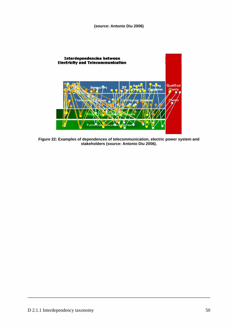
D 2.1.1 Interdependency taxonomy 50
(source: Antonio Diu 2006)
Figure 22: Examples of dependences of telecommunication, electric power system and
stakeholders (source: Antonio Diu 2006).
D 2.1.1 Interdependency taxonomy 51
7. Methodological Approach [WS03] An important reason for such cascading effects is that our daily life is networked via information and communications technology (ICT). The ICT penetration of critical infrastructures like electricity, telecommunication, transportation, finance, and others led to global (inter)dependencies. Figure 1 (see page 22) gives a first impression of the complexity of mutual dependent infrastructures. It will be used in this paper to discuss the different aspects in modelling and simulation of (inter)dependent critical infrastructures.
7.1 Risk and prevention Risk prevention is indispensable, but demands extensive information about installations, processes, actors etc. and can restrict the informational freedom of many citizens. Restrictions like large area monitoring for example are contradictory to the constitutional concept of nationwide freedom. Thus everything has to be done to avoid the necessity for such interventions as far as possible. But in cases where such interventions can not be avoided, limits must be set in accordance with the rule of law. These limits must be wide enough to admit risk prevention and must be narrow enough to prevent that the precaution determines our daily life. The challenge is to protect infrastructures especially by technical measures like MIT and at the same time to establish a legal framework that facilitates the development and use of such technical solutions. Elements of technical solution strategies could be redundancy, diversification6, decentralisation7, graceful degradation8, decoupled arrangement9, reduction of complexity as well as so called “Privacy Enhancing Technologies” with the potentiality of encryption and steganography, signatures, anonymity and pseudonymity [R03]. 7.2 Handling of complex systems The purpose of this chapter is to introduce a practicable process model for CIP that will help to understand critical infrastructures as a cybernetic system and to derive decision support instruments suitable for improving their survivability. But before discussing CIP as a complex system some important characteristics of complex systems and prevalent shortcomings in dealing with complex systems have to be discussed.
7.3 Fundamentals of complex systems
Knowledge of the individual parts of a system is not enough to be able to assess a complex system. It is also important to know their cross-linking. Concentration on details often prevents recognition of the interrelationships. As pattern recognition shows it is more important to put the parts into the right context than to examine them in greater detail. Intervention into the network changes the relationships between the parts and consequently the character of the system. Ecological systems for example are open systems and remain viable through permanent
6 Usage of diverse methods, materials and components 7 distribution of the damage potential 8 outage in direction of a less bad status 9 with respect to time and space
D 2.1.1 Interdependency taxonomy 52
exchange with their environment. Such an exchange causes characteristics like feedbacks and self-regulation that are not contained in the individual components of the system. Therefore the survivability of a complex system can not be derived alone from the survivability of its components. Primarily survivability depends on the fact that the organisation of the network follows cybernetic principles.
Vester [V00] showed that cybernetic interpretation of complex systems can produce quite accurate descriptions of system behaviour, even when working with fuzzy concepts and incomplete data. 7.4 Prevalent shortcomings
According to Dörner [D76] we make consistently strategic mistakes in dealing with complex systems. Typical mistakes are:
• Incorrect definition of objectives • Inadequate modelling • Inadequate solution strategies. 7.4.1 Incorrect definition of objectives
Sub-optimisation and selection of inappropriate objective functions are often observed in dealing with complex systems. Instead to focus on survivability of the whole system, planners often follow repair service strategies or select shareholder value as objective function. The consequence is that sustainability, stability and robustness of the system are not furthered, instead considering improvement of the survivability of the whole system as main objective function. In the long run sub-optimization of individual system components leads to inefficiency and also often to irreversible erroneous trends.
7.4.2 Inadequate modelling of the system
Typical modelling errors are:
(1) Inadequate aggregation levels (2) Negligence of important interdependencies (3) Waiving of essential system components (4) Negation of soft factors (5) Disregarding of disturbances (6) Indiscriminate application of extrapolation methods.
(1) Inadequate aggregation levels
Often the aggregation levels of system components are not adequate to the problem. Consequentially too many details lead to an information overload. Large quantities of data are collected, that however fail to reveal the system structure. Important relationships and interactions will be overlooked. The bulk of data cannot be evaluated because of lack of criteria for allocating them (e.g. feedbacks, self-regulation) and no attempt is made to allow for the dynamic character of the system.
D 2.1.1 Interdependency taxonomy 53
Systemic analysis means first of all to recognise the interactions of details on a suitable aggregation level. Adequate pattern recognition has to reduce the volume of data on the essential key components and network them.
Requirement: development of an adequate data hierarchy
(2) Negligence of important interdependencies
Without knowledge of the network with interdependencies between the components the performance of the system cannot be assessed even if the individual components are studied in detail. The role of the components in the network remains unknown. Symptoms instead problems are addressed.
Requirement: pattern recognition, causal mapping
(3) Waiving of essential system components
There is tendency to concentrate on a feature after correctly recognising it. In so doing, one however ignores very grave consequences in other areas. Conscious or unconscious waiving of essential components reduces the volume of data, but it gives a false impression of the system.
Requirement: As we have to know what parts of the system are indispensable, systematic compilation of the essential components is necessary (for example by means of creativity workshops)
(4) Negation of soft factors
The negation of soft factors such as consensus, confidence, attractiveness, satisfaction, motivation, quality of life etc. leads also to an incomplete and biased description of the system. These qualitative factors are as important for the system performance as hard factors.
Requirement: fuzzy sets for mapping of soft factors and fuzzy concepts
(5) Disregarding of disturbances
Caught up in the web of linear, causal patterns of thinking, people intend to adjust all planning factors as exactly as possible without providing for cushions as if it were a closed system that does not need to worry about disturbances from outside.
Requirement: fault tolerance
(6) Indiscriminate application of the extrapolation methodology
Indiscriminate application of the extrapolation method leads often to wrong solutions, because the extrapolation methodology can – if at all - forecast the behaviour of a complex system only for a narrow time horizon.
Interrelationships or disturbances of a complex system can reveal surprising effects which are seldom manifested by a direct cause-and-effect relationship between neighbouring elements. This is one of the main headaches in planning and understanding the system, because the effects are so complex, that extrapolation to estimate the results will fail. Forecast models based on such a linear method will not function properly, because they can only produce a reliable answer if all the data concerning the interactions are known and the systems are closed ones. As we will not be able to gather all the data, and as all viable systems are open systems, models of this type are inappropriate to describe the behaviour of complex systems.
Requirement: identification of feedback loops and self-regulation
D 2.1.1 Interdependency taxonomy 54
7.4.3 Inadequate solution strategies
Too often we confine ourselves to isolated changes although we were tasked to develop holistic or systemic solution strategies. But we are lacking in networked thinking that is a prerequisite for developing holistic strategies. Typical mistakes in selection of solution strategies are:
(1) Ignoring of side-effects (2) Adhere to repair strategies (3) Tendency to over-reaction (4) Tendency to dominating behaviour.
(1) Ignoring of side-effects
Linear-causal planning tries very determined to improve the situation, but often side-effects of the selected measures remain uncovered. Policy-tests are required to reveal side-effects of strategies.
Requirement: policy-tests in different scenarios
(2) Repair strategies
Repair strategies are not only costly but may also cause additional consequential damages, because they disregard interdependencies between the system components. The better strategy is to find constellations of the system in which such damages have a low probability to occur.
Requirement: prevention by self-regulation
(3) Tendency to over-reaction
Often operators are very hesitant at first when using correction measures. But they accelerate sharply when nothing happens in system behaviour. Then, when the first unintended effects become apparent, they execute an emergency braking. At this stage they negate that the impacts of the first small corrections have been inwardly accumulated due to time delays.
Requirement: systematic strategy development taking into account the time behaviour of the system.
(4) Tendency to dominating behaviour
The attitude to be able to change system behaviour and the belief to be aware of all system functions will often lead to dominant pattern of behaviour which is completely unsuitable when dealing with complex systems. An approach which considers and uses the intrinsic system rules and self-regulating properties is much more effective here. Development and application of suitable strategies is an essential part of the problem solution. The cybernetic relationships of the system have to be identified to allow for corresponding control loops and feedbacks.
Requirement: analysis of networks with respect to cybernetic rules 7.4.4 Sources of fault
No body intends consciously to develop wrong objectives, disregard side-effects ore over-react. Even dominating behaviour is not practised intentionally as end in itself. Why do we make such principal mistakes in dealing with complex systems? The answer may have three main causes:
(1) Disconnection of the reality (2) Disregard of control loops
D 2.1.1 Interdependency taxonomy 55
(3) Insufficient planning horizon.
(1) Disconnection of the reality
Disconnecting of reality in single areas negates the interdependencies between these areas. We are used to consider single not connected disciplines.
Our education does not favour thinking in networks. Our lack in cybernetic understanding does not allow recognising that a complex system is like an organism and that cause-and-effect chains can not be recovered directly. Likewise, consequences of impacts can also not be observed immediately due to response time and delays within the network.
Requirement: holistic approach, causal method, capability to simulate the response time of the system
(2) Disregard of control loops
Survivable systems contain control loops that enable the system to absorb disturbances without external interventions.
Thereby the system becomes fault tolerant and robust with regard to disturbances. Faults may happen, but the system does not collapse. But we tend to disconnect self-regulation instead to use the capacity of control loops. The consequence is that we combat symptoms instead causes.
Requirements: identification and use of self-regulation
(3) Insufficient planning horizon
The lack of knowledge concerning indirect effects with their time delays leads to the fact that we normally realise the impact of our interventions too late. Therefore extrapolations are not qualified except for a few exceptions. Policy-tests have to be carried out. The results of these policy-tests deliver important hints for the strategy development. The forecast will refer less to the fact which events when occur, but to the fact how the system behaves and how it reacts to certain events.
Requirement: capability to simulate response time of the system 7.4.5 Modelling and Simulation Challenges
It should be apparent from the discussion in chapter 3 that a comprehensive analysis of interdependencies is a daunting challenge. Today’s modelling and simulation tools are only beginning to address many of the issues outlined above: the “science” of infrastructure interdependencies is relatively immature. Some models and computer simulations exist for aspects of individual infrastructures, but simulation frameworks that allow the coupling of multiple interdependent infrastructures to address infrastructure protection, mitigation, response, and recovery issues are only beginning to emerge. However, simply “hooking” several existing infrastructure models together generally does not work: every model has its own unique assumptions, data, and numerical requirements (such as time-step sizes, scaling limitations, or computational algorithms) that may not be compatible with other models. Further, such approaches generally do not capture emergent behaviour, a key element of interdependency analysis.
Data In addition to architecture, the nature of the available data is a fundamental concern of any modelling and simulation effort:
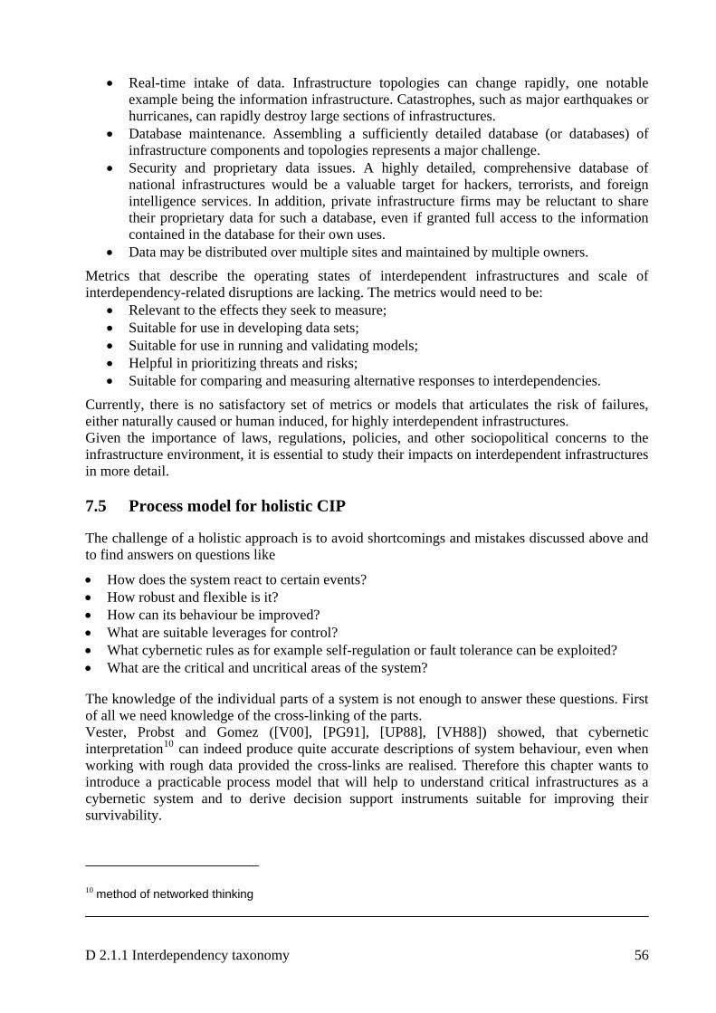
D 2.1.1 Interdependency taxonomy 56
• Real-time intake of data. Infrastructure topologies can change rapidly, one notable example being the information infrastructure. Catastrophes, such as major earthquakes or hurricanes, can rapidly destroy large sections of infrastructures.
• Database maintenance. Assembling a sufficiently detailed database (or databases) of infrastructure components and topologies represents a major challenge.
• Security and proprietary data issues. A highly detailed, comprehensive database of national infrastructures would be a valuable target for hackers, terrorists, and foreign intelligence services. In addition, private infrastructure firms may be reluctant to share their proprietary data for such a database, even if granted full access to the information contained in the database for their own uses.
• Data may be distributed over multiple sites and maintained by multiple owners.
Metrics that describe the operating states of interdependent infrastructures and scale of interdependency-related disruptions are lacking. The metrics would need to be:
• Relevant to the effects they seek to measure; • Suitable for use in developing data sets; • Suitable for use in running and validating models; • Helpful in prioritizing threats and risks; • Suitable for comparing and measuring alternative responses to interdependencies.
Currently, there is no satisfactory set of metrics or models that articulates the risk of failures, either naturally caused or human induced, for highly interdependent infrastructures. Given the importance of laws, regulations, policies, and other sociopolitical concerns to the infrastructure environment, it is essential to study their impacts on interdependent infrastructures in more detail. 7.5 Process model for holistic CIP
The challenge of a holistic approach is to avoid shortcomings and mistakes discussed above and to find answers on questions like
• How does the system react to certain events? • How robust and flexible is it? • How can its behaviour be improved? • What are suitable leverages for control? • What cybernetic rules as for example self-regulation or fault tolerance can be exploited? • What are the critical and uncritical areas of the system?
The knowledge of the individual parts of a system is not enough to answer these questions. First of all we need knowledge of the cross-linking of the parts. Vester, Probst and Gomez ([V00], [PG91], [UP88], [VH88]) showed, that cybernetic interpretation10 can indeed produce quite accurate descriptions of system behaviour, even when working with rough data provided the cross-links are realised. Therefore this chapter wants to introduce a practicable process model that will help to understand critical infrastructures as a cybernetic system and to derive decision support instruments suitable for improving their survivability.
10 method of networked thinking
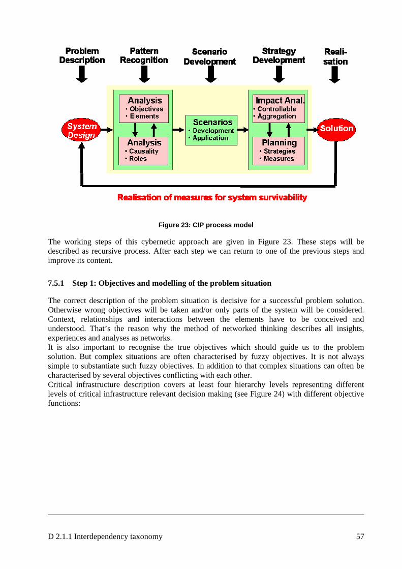
D 2.1.1 Interdependency taxonomy 57
Figure 23: CIP process model
The working steps of this cybernetic approach are given in Figure 23. These steps will be described as recursive process. After each step we can return to one of the previous steps and improve its content.
7.5.1 Step 1: Objectives and modelling of the problem situation
The correct description of the problem situation is decisive for a successful problem solution. Otherwise wrong objectives will be taken and/or only parts of the system will be considered. Context, relationships and interactions between the elements have to be conceived and understood. That’s the reason why the method of networked thinking describes all insights, experiences and analyses as networks. It is also important to recognise the true objectives which should guide us to the problem solution. But complex situations are often characterised by fuzzy objectives. It is not always simple to substantiate such fuzzy objectives. In addition to that complex situations can often be characterised by several objectives conflicting with each other. Critical infrastructure description covers at least four hierarchy levels representing different levels of critical infrastructure relevant decision making (see Figure 24) with different objective functions:
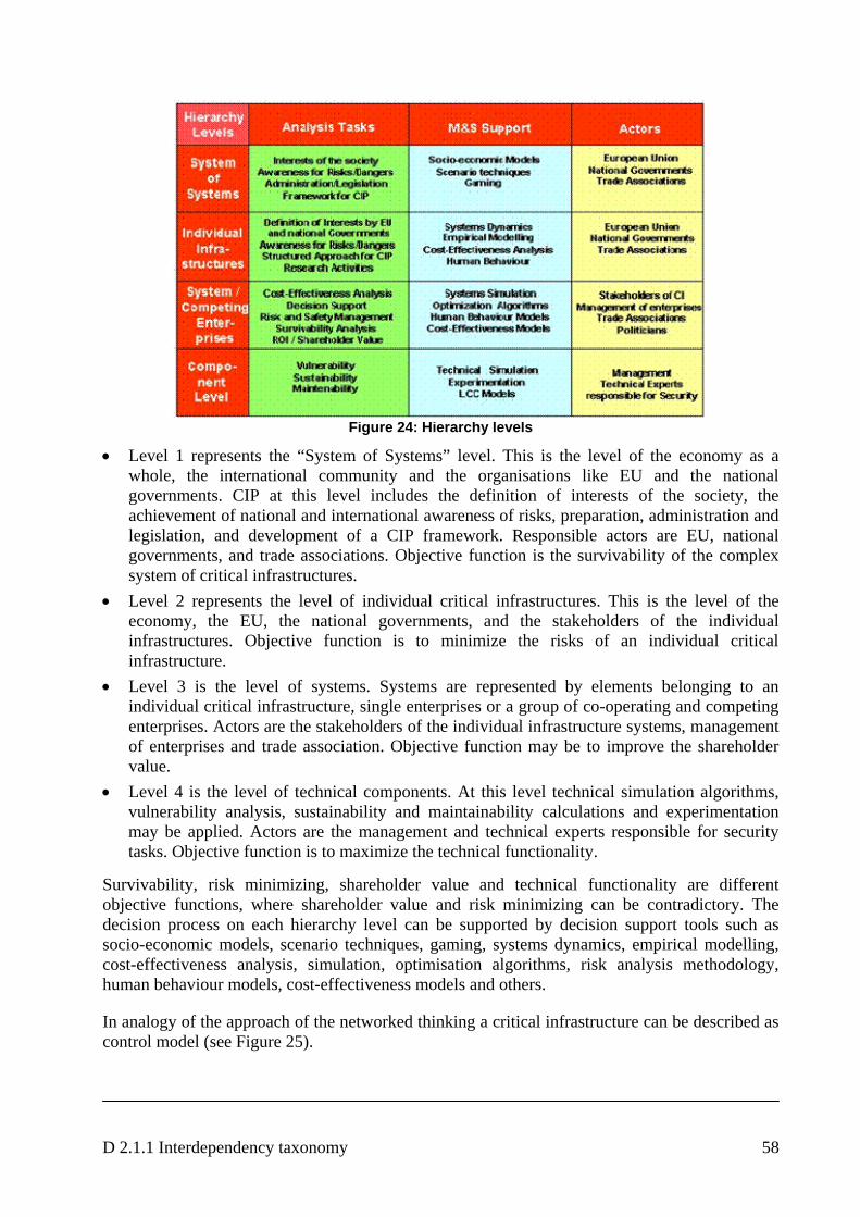
D 2.1.1 Interdependency taxonomy 58
Figure 24: Hierarchy levels
• Level 1 represents the “System of Systems” level. This is the level of the economy as a whole, the international community and the organisations like EU and the national governments. CIP at this level includes the definition of interests of the society, the achievement of national and international awareness of risks, preparation, administration and legislation, and development of a CIP framework. Responsible actors are EU, national governments, and trade associations. Objective function is the survivability of the complex system of critical infrastructures.
• Level 2 represents the level of individual critical infrastructures. This is the level of the economy, the EU, the national governments, and the stakeholders of the individual infrastructures. Objective function is to minimize the risks of an individual critical infrastructure.
• Level 3 is the level of systems. Systems are represented by elements belonging to an individual critical infrastructure, single enterprises or a group of co-operating and competing enterprises. Actors are the stakeholders of the individual infrastructure systems, management of enterprises and trade association. Objective function may be to improve the shareholder value.
• Level 4 is the level of technical components. At this level technical simulation algorithms, vulnerability analysis, sustainability and maintainability calculations and experimentation may be applied. Actors are the management and technical experts responsible for security tasks. Objective function is to maximize the technical functionality.
Survivability, risk minimizing, shareholder value and technical functionality are different objective functions, where shareholder value and risk minimizing can be contradictory. The decision process on each hierarchy level can be supported by decision support tools such as socio-economic models, scenario techniques, gaming, systems dynamics, empirical modelling, cost-effectiveness analysis, simulation, optimisation algorithms, risk analysis methodology, human behaviour models, cost-effectiveness models and others.
In analogy of the approach of the networked thinking a critical infrastructure can be described as control model (see Figure 25).
D 2.1.1 Interdependency taxonomy 59
Figure 25: CIP control model
Elements of critical infrastructures are • Actors for example operator, data administrator, user and others • Controllable factors as computer, network, switches etc and • Criteria or indicators that indicate how the objective of the system will be fitted. Criteria
indicating how well the considered system fulfils its mission can be for example: integrity, safety, reliability and others.
Actors control the controllable factors and vice versa controllable factors can influence the behaviour of actors. Controllable factors determine the indicators and vice versa the indicators regulate the controllable factors (e.g., refrigeration will be activated if the temperature is too high), as well as the behaviour of the actors.
As critical infrastructures are not isolated, so called non-controllable factors influence the system. Non-controllable factors are factors that can not be influenced by critical infrastructure itself. Examples for such non controllable factors can be liability, international standards and others. Non-controllable factors influence or disturb actors and controllable factors of critical infrastructure. External and internal factors influence the indicators that determine the value of the objective function as for example technical functioning. The value of the objective function causes actors to change controllable factors, if the value of the objective function lies outside of normal sector. That means each critical infrastructure can be treated as classical control model with feedback loops. 7.5.2 Step 2: Analysis of causality
Tools are needed to investigate interrelationships, influences, time periods and changes in order to get a comprehensive understanding of the problem. Networks allow us to describe the causality of the relationships and to analyse their characteristics provided we have all relevant relationships registered with respect to their intensity, impact direction and time aspects.
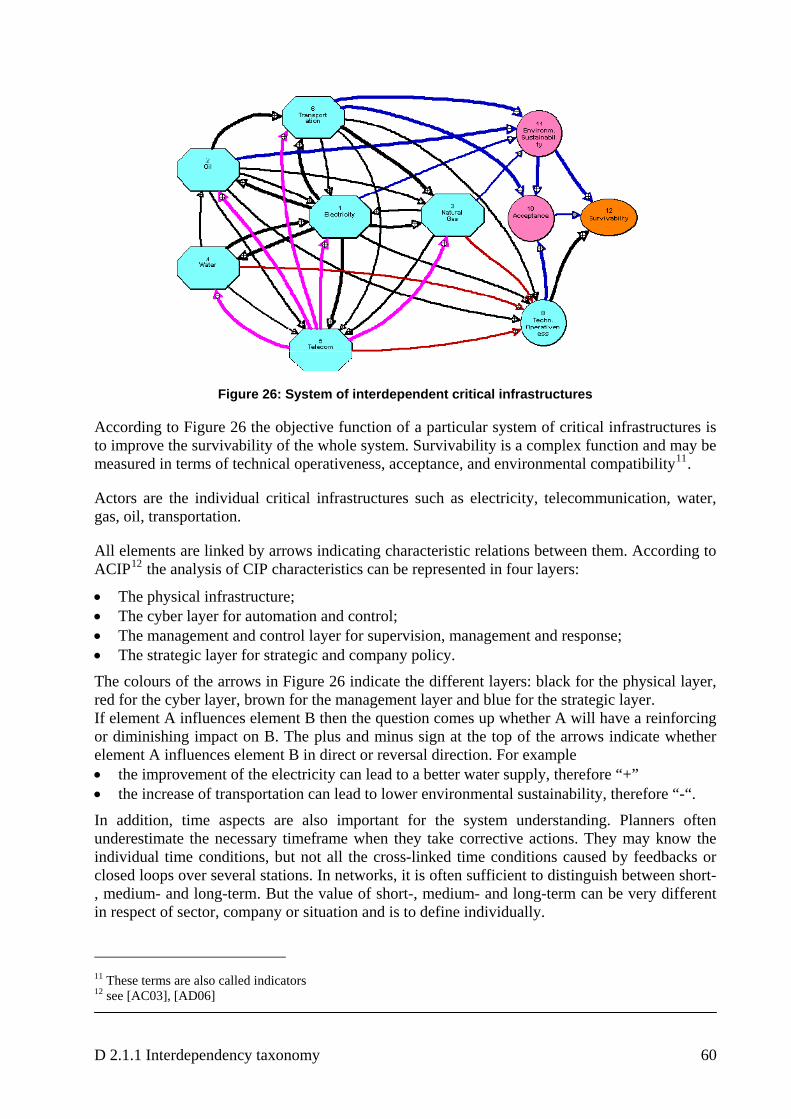
D 2.1.1 Interdependency taxonomy 60
Figure 26: System of interdependent critical infrastructures
According to Figure 26 the objective function of a particular system of critical infrastructures is to improve the survivability of the whole system. Survivability is a complex function and may be measured in terms of technical operativeness, acceptance, and environmental compatibility11.
Actors are the individual critical infrastructures such as electricity, telecommunication, water, gas, oil, transportation.
All elements are linked by arrows indicating characteristic relations between them. According to ACIP12 the analysis of CIP characteristics can be represented in four layers:
• The physical infrastructure; • The cyber layer for automation and control; • The management and control layer for supervision, management and response; • The strategic layer for strategic and company policy.
The colours of the arrows in Figure 26 indicate the different layers: black for the physical layer, red for the cyber layer, brown for the management layer and blue for the strategic layer. If element A influences element B then the question comes up whether A will have a reinforcing or diminishing impact on B. The plus and minus sign at the top of the arrows indicate whether element A influences element B in direct or reversal direction. For example • the improvement of the electricity can lead to a better water supply, therefore “+” • the increase of transportation can lead to lower environmental sustainability, therefore “-“.
In addition, time aspects are also important for the system understanding. Planners often underestimate the necessary timeframe when they take corrective actions. They may know the individual time conditions, but not all the cross-linked time conditions caused by feedbacks or closed loops over several stations. In networks, it is often sufficient to distinguish between short-, medium- and long-term. But the value of short-, medium- and long-term can be very different in respect of sector, company or situation and is to define individually.
11 These terms are also called indicators 12 see [AC03], [AD06]
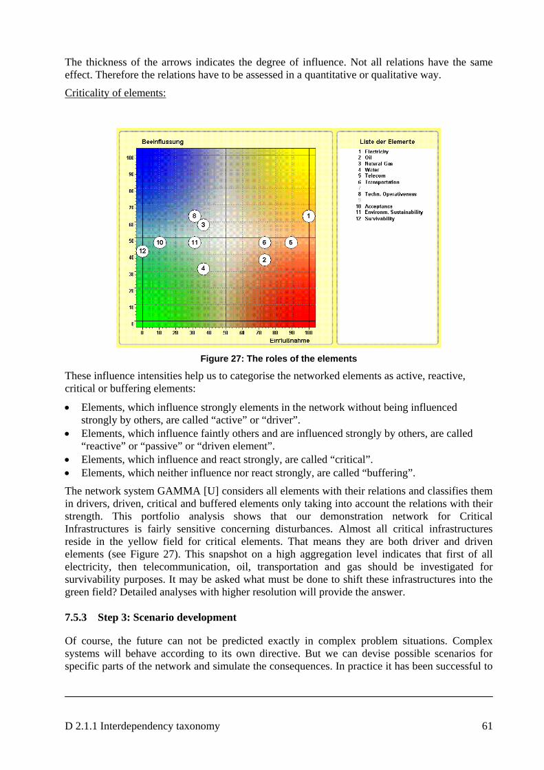
D 2.1.1 Interdependency taxonomy 61
The thickness of the arrows indicates the degree of influence. Not all relations have the same effect. Therefore the relations have to be assessed in a quantitative or qualitative way.
Criticality of elements:
Figure 27: The roles of the elements
These influence intensities help us to categorise the networked elements as active, reactive, critical or buffering elements:
• Elements, which influence strongly elements in the network without being influenced strongly by others, are called “active” or “driver”.
• Elements, which influence faintly others and are influenced strongly by others, are called “reactive” or “passive” or “driven element”.
• Elements, which influence and react strongly, are called “critical”. • Elements, which neither influence nor react strongly, are called “buffering”.
The network system GAMMA [U] considers all elements with their relations and classifies them in drivers, driven, critical and buffered elements only taking into account the relations with their strength. This portfolio analysis shows that our demonstration network for Critical Infrastructures is fairly sensitive concerning disturbances. Almost all critical infrastructures reside in the yellow field for critical elements. That means they are both driver and driven elements (see Figure 27). This snapshot on a high aggregation level indicates that first of all electricity, then telecommunication, oil, transportation and gas should be investigated for survivability purposes. It may be asked what must be done to shift these infrastructures into the green field? Detailed analyses with higher resolution will provide the answer. 7.5.3 Step 3: Scenario development
Of course, the future can not be predicted exactly in complex problem situations. Complex systems will behave according to its own directive. But we can devise possible scenarios for specific parts of the network and simulate the consequences. In practice it has been successful to

D 2.1.1 Interdependency taxonomy 62
develop a basic scenario and some alternative scenarios, for example an optimistic and pessimistic scenario. Scenario development requires the following work steps (see [D1.2.1]):
• Determination of the necessary timeframe • Identification of the influencing factors within the network • Selection of the relevant scenario areas • Development of the basic scenario • Development of alternative scenarios • Interpretation of the scenarios.
7.5.4 Step 4: Impact analysis
In this step control possibilities should be identified. In doing so, we have to distinguish between controllable elements, non-controllable elements and indicators. Controllable elements are to be considered for steering tasks as well as disturbances. Non-controllable elements are to be monitored with respect to preventive actions. Indicators notice the degree of success of a steering measure or the degree of impairment caused by disturbances. Our main task is to improve the survivability of the system of critical infrastructures. So, the question comes up which elements influence the survivability of the whole system. Of course the indicators “environmental sustainability”, “technical operativeness” and “acceptance” use immediately influence on “survivability”. But these indicators are not directly controllable and therefore they are not suitable for control actions. These indicators are directly influenced by the output of the critical infrastructures and this output can be directly controlled by the management. But as critical infrastructures are highly aggregated elements in this network, we are not yet able to say how these elements should be controlled by which measures. For this purpose it is to determine who should be the controller. According to his competencies he can steer certain elements or not. That means first of all we have to determine the level of the steering activities.
Figure 28: Hierarchical Structure
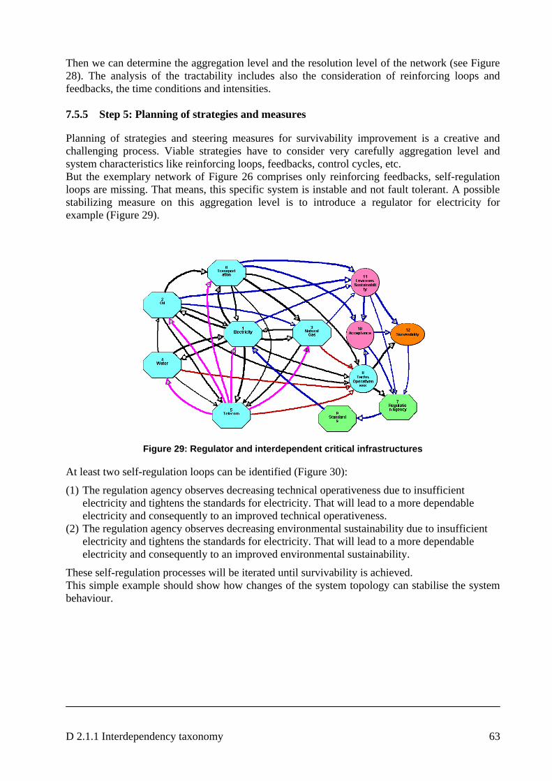
D 2.1.1 Interdependency taxonomy 63
Then we can determine the aggregation level and the resolution level of the network (see Figure 28). The analysis of the tractability includes also the consideration of reinforcing loops and feedbacks, the time conditions and intensities. 7.5.5 Step 5: Planning of strategies and measures
Planning of strategies and steering measures for survivability improvement is a creative and challenging process. Viable strategies have to consider very carefully aggregation level and system characteristics like reinforcing loops, feedbacks, control cycles, etc. But the exemplary network of Figure 26 comprises only reinforcing feedbacks, self-regulation loops are missing. That means, this specific system is instable and not fault tolerant. A possible stabilizing measure on this aggregation level is to introduce a regulator for electricity for example (Figure 29).
Figure 29: Regulator and interdependent critical infrastructures
At least two self-regulation loops can be identified (Figure 30):
(1) The regulation agency observes decreasing technical operativeness due to insufficient electricity and tightens the standards for electricity. That will lead to a more dependable electricity and consequently to an improved technical operativeness.
(2) The regulation agency observes decreasing environmental sustainability due to insufficient electricity and tightens the standards for electricity. That will lead to a more dependable electricity and consequently to an improved environmental sustainability.
These self-regulation processes will be iterated until survivability is achieved. This simple example should show how changes of the system topology can stabilise the system behaviour.
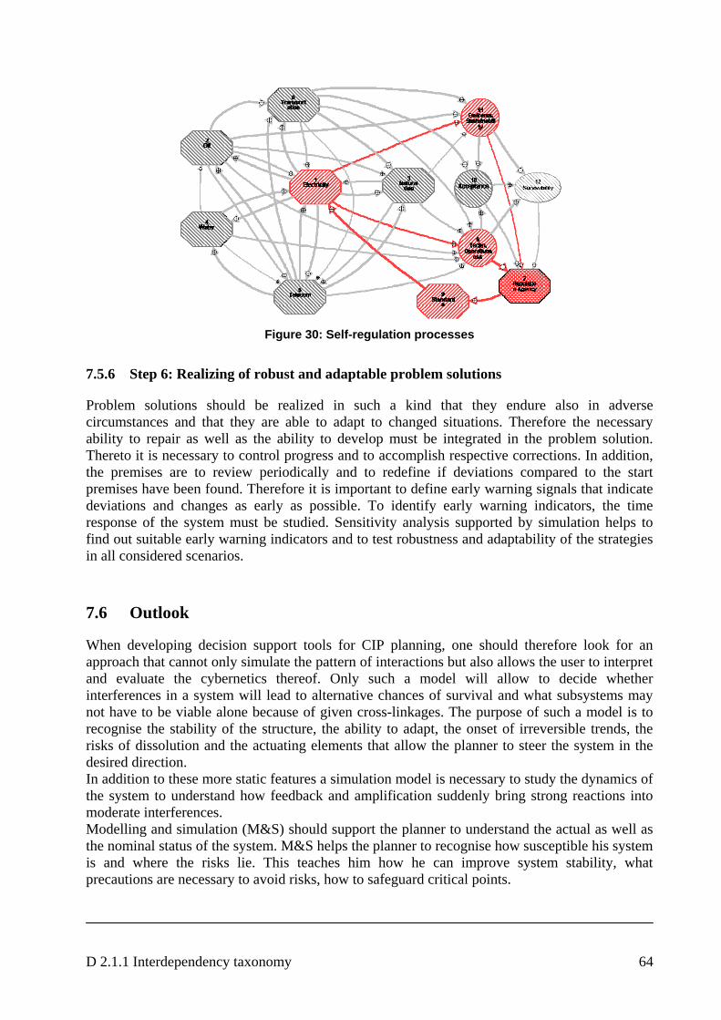
D 2.1.1 Interdependency taxonomy 64
Figure 30: Self-regulation processes
7.5.6 Step 6: Realizing of robust and adaptable problem solutions
Problem solutions should be realized in such a kind that they endure also in adverse circumstances and that they are able to adapt to changed situations. Therefore the necessary ability to repair as well as the ability to develop must be integrated in the problem solution. Thereto it is necessary to control progress and to accomplish respective corrections. In addition, the premises are to review periodically and to redefine if deviations compared to the start premises have been found. Therefore it is important to define early warning signals that indicate deviations and changes as early as possible. To identify early warning indicators, the time response of the system must be studied. Sensitivity analysis supported by simulation helps to find out suitable early warning indicators and to test robustness and adaptability of the strategies in all considered scenarios.
7.6 Outlook
When developing decision support tools for CIP planning, one should therefore look for an approach that cannot only simulate the pattern of interactions but also allows the user to interpret and evaluate the cybernetics thereof. Only such a model will allow to decide whether interferences in a system will lead to alternative chances of survival and what subsystems may not have to be viable alone because of given cross-linkages. The purpose of such a model is to recognise the stability of the structure, the ability to adapt, the onset of irreversible trends, the risks of dissolution and the actuating elements that allow the planner to steer the system in the desired direction. In addition to these more static features a simulation model is necessary to study the dynamics of the system to understand how feedback and amplification suddenly bring strong reactions into moderate interferences. Modelling and simulation (M&S) should support the planner to understand the actual as well as the nominal status of the system. M&S helps the planner to recognise how susceptible his system is and where the risks lie. This teaches him how he can improve system stability, what precautions are necessary to avoid risks, how to safeguard critical points.
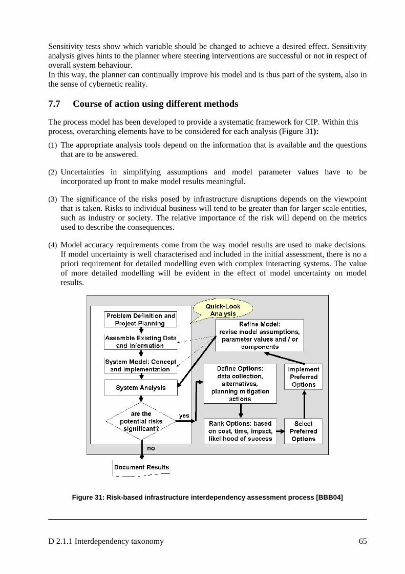
D 2.1.1 Interdependency taxonomy 65
Sensitivity tests show which variable should be changed to achieve a desired effect. Sensitivity analysis gives hints to the planner where steering interventions are successful or not in respect of overall system behaviour. In this way, the planner can continually improve his model and is thus part of the system, also in the sense of cybernetic reality. 7.7 Course of action using different methods
The process model has been developed to provide a systematic framework for CIP. Within this process, overarching elements have to be considered for each analysis (Figure 31):
(1) The appropriate analysis tools depend on the information that is available and the questions that are to be answered.
(2) Uncertainties in simplifying assumptions and model parameter values have to be incorporated up front to make model results meaningful.
(3) The significance of the risks posed by infrastructure disruptions depends on the viewpoint that is taken. Risks to individual business will tend to be greater than for larger scale entities, such as industry or society. The relative importance of the risk will depend on the metrics used to describe the consequences.
(4) Model accuracy requirements come from the way model results are used to make decisions. If model uncertainty is well characterised and included in the initial assessment, there is no a priori requirement for detailed modelling even with complex interacting systems. The value of more detailed modelling will be evident in the effect of model uncertainty on model results.
Figure 31: Risk-based infrastructure interdependency assessment process [BBB04]
D 2.1.1 Interdependency taxonomy 66
7.7.1 Quick-look analysis [BBB04]
The quick-look analysis is based on easily obtained information and is used to identify potentially significant risks, given what is known about the system. It provides the basis for decisions regarding the best or necessary actions by
• Identifying the obvious risks, • Highlighting areas that do not require further study, • Allowing rapid identification and implementation of mitigation and protection activities
for easy to solve or immediate problems, • Minimising unnecessary data collection and analyses, and • Providing justification and focus for more detailed analyses and data collection.
The first step is problem definition and project planning. Analysts, LCCI providers and technology providers within IRRIIS are working together to define the problem and understand the system. The IRRIIS team has developed background information questionnaires to elicit information that helps the project team to understand the system components requirements and operations, specify the purpose of the proposed system analysis, identify and rank the consequences of concern, identify the information that is used to make decisions, and identify the information that can be used to construct the assessment.
The initial data collection step included system requirements [D1.1.3], existing models and tools [D1.1.1], historical data13, standard operating procedures [CEER05] and demands [VDE06].
Once the initial data are collected and reviewed, a conceptual model of the system has to be developed. Comparison with historical system behaviour14 (e.g. [AE04], [BN03], [UCTE03], [UC04]) can help verify the model, provide information on the uncertainty in model output and indicate model limitations.
The analysis phase consists of summarising and interpreting the results. If the analysis show that additional modelling or information is required to reduce uncertainty then another iteration may begin. The first major decision point in the assessment is to determine if there are significant risks, based on the results of the analysis. This step marks the end of the quick-look analysis, which identifies potential problems (vulnerabilities, consequences, risks) based on existing information. The assessment proceeds if the risks identified in the analysis are potentially significant and mitigation or uncertainty reduction is considered. Figure 27 shows how those results can be grouped in a two-dimensional graph for prioritisation with respect to criticality of the different components of the considered system.
If further refinement of the estimated risks is required in order to make decisions regarding the prioritisation of mitigation and protection activities, the existing quick-look models can be used to evaluate the sensitivity of the model results to parameter and model uncertainty. This sensitivity can be used to define potential data collection activities or model refinements.
Selecting the preferred options – e.g. MIT add-on components - is the second major decision point for the customer, who must decide what actions will be taken given the risks, the uncertainties in those risks and potential effectiveness of the identified options.
13 See “Historical Outage Database” in [D1.2.2]
14 see [D1.2.2] „Risk Analysis“ Appendix G: Description of IABG´s outage database
D 2.1.1 Interdependency taxonomy 67
Implementing the mitigation or data collection options may provide additional data, model results or system modifications. At this point, the assessment model(s) can be revised. This begins the next iteration of the assessment. Each of the risk assessment iterations is performed on a better-characterised or modified system. This process efficiently focuses analytical effort, data collection and mitigation. A set of modelling tools will be developed to support this iterative process.
7.7.2 System Dynamics
Infrastructure dependencies can propagate disturbances across many infrastructures and over long distances. System dynamics modelling is used to simulate the interconnections between infrastructures, track the flow of commodities and services necessary to maintain system operation and identify chains of (inter)dependencies, which could create hidden failures. The screening process supported by these simulations also provides the technical justification for additional data collection or model resolution where the uncertainty regarding the risks makes decisions difficult.
This approach allows quantification of system dynamics given existing information and projections of system operation and supply requirements, evaluation of model and parameter uncertainties, analysis of events of various scenarios. Analyses supported by these models include: identification of system limitations, limiting elements or conditions, potential vulnerabilities, potential unintended consequences of preventative, regulatory or other procedural system changes.
7.7.3 Agent-based models
A second type of modelling approach is agent-based modelling. In contrast to systems dynamics, agent-based modelling is a bottom-up approach. Agent-based models typically consist of many dispersed agents acting in parallel without a global controller responsible for the behaviour of all. Agents usually perceive part of the state of the environment (e.g. other agents), have an internally state and execute actions in the environment based only on the perceived state of the environment and the internal state. There are clear borders between an agent, its environment and other agents. Each agent is responsible for his own behaviour. This behaviour influences other agents or the environment through the actions taken by the agent (communication is seen as an action). The behaviour of the whole system arises from the behaviour of the individual agents. Typically, very complex system behaviours emerge from very simple agent behaviour.
The complexity of the system arises more from interactions occurring between agents than from any complexity inherent in an individual agent. Agent-based modelling techniques have already been applied to many examples of human social phenomena including trade, transportation, migration, group formation, combat, interaction with an environment, propagation of disease, population dynamics, and economic interactions between decision makers in infrastructure networks [BBB04].
One big advantage of agent-based models is that someone does not have to model the overall system behaviour which is often far to complex. The modeller can stick to the individual behaviour of the components of the system and how these components are linked. E.g. to model an electric power infrastructure, agents can represent generators, transformers, sub-stations, consumers, operators, services, etc. Of course, not every physical component of the system has to be represented by an agent, sub-systems can be identified and modelled as a single agent.

D 2.1.1 Interdependency taxonomy 68
The backside of agent-based models is that they usually can not be analysed in a strict mathematical way. Simulations have to be performed and the behaviour of the system has to be observed in order to analyse it using statistical methods.
There are several tools available to support the implementation of agent-based models for simulations. These tools range from supporting software libraries (e.g. SWARM [SWARM], Repast[NO06] to user-friendly modelling systems with advanced user interfaces [e.g. SeSAM [SESAM]). A short-coming of all these tools is that they do not support the interoperability of different simulators. So, everything has to be modelled in the agent-based model. This makes it difficult if existing simulators shall be used. But, if advanced simulators are available for subsystems of the system to be modelled it is preferable to use these simulators, especially if these subsystems are itself very complex. This is e.g. the case for the electric power infrastructure where many good simulators exist to calculate the power flow. Therefore, the IRRIIS project will develop its own environment for agent-based modelling and simulation that will take especially these inter-operability issues into account,
7.7.4 Graphs [GV04]
Since the promotion of the concept of complexity induced vulnerability requires a versatile modus operandi, able to accommodate a variety of user-defined, convincing applications, the concept of graphs is also used as a comprehensive expression of multi-component systems and their internal connectivity, where:
• The actors or parts of the system are the nodes of the graph. • The interactions of the actors and parts are represented by directed links between nodes. • The graph is customised to a system by attaching a set of features to the nodes,
appropriately quantified and normalised on a vulnerability-relevant scale.
The nodes are the irreducible objects / subjects of a system showing a sufficient degree of coherence to play a coordinated part in the internal interaction game of the considered system.
The links connect the nodes in the sense that the nodes exchange information, energy, and/or commodities. Normally, exchanges between nodes are controlled by specific objective functions in a hierarchic way. Links are of critical importance in evaluating security, efficiency, sustainability, etc. of a system.
Features characterise the nodes and should be selected aiming at the objectives of the analysis (e.g. vulnerability assessment). Considering the vulnerability of a system, features enter the quantitative vulnerability assessment through values and weights.
Values are attached to the nodes and are represented by a decimal number in the range one to nine, assumed to be in direct proportion to the degree of vulnerability (1 = lowest vulnerability, 9 = highest vulnerability).
Weights compare features in terms of their relative vulnerability relevance and range from 0.0 to 1.0.
The topology of electricity and telecommunication can be described by means of graph theory and their connectivity can be studied. But there are two complementary interpretations of the internal connectivity of the system: benign and cautious. According to the benign interpretation, the more extensive and multilateral the exchanges between the elements of a system are, the better the system is functional. The other way of looking at high connectivity reveals risks that a disturbance initiated at a specific node propagates across the system. In this interpretation, a higher connectivity means a higher vulnerability [GV04]:
D 2.1.1 Interdependency taxonomy 69
Assumption 1: a higher internal connectivity is a desirable quality only to the extent that the cumulated vulnerability of the connected nodes is tolerable.
Assumption 2: the higher the vulnerability of the nodes involved in the exchange path of any node of origin, the higher the vulnerability induced in the overall system.
Assumption 3: the higher the cumulated vulnerability of the nodes the higher the system vulnerability.
Considering catastrophic failures, each network should avoid a too high connectivity so that cascading effects can be fenced in time [BA04].
8. Generic Structure of Cascading Failures
Dependencies of different services in telecommunication and electricity infrastructure have been and are increasing. For example, there are dependencies between different providers within the same sector. Similarly, there is a manifold dependence of electricity infrastructure from telecommunication infrastructure. This trend is also increasing. Consequently, their vulnerability and security are raising major concerns worldwide. For instance, the normal operation of electricity and telecommunications systems is maintained only if there is a steady supply of electricity. On the other hand, the generation and delivery of electric power cannot be ensured without provision to the electricity infrastructure of various telecommunications and computer services far data transfer and control purposes. These (inter)dependencies are strengthening their grip as the usage of the internet, intranet and other wide area computer networks is becoming prevalent. The strong reliance of critical infrastructures on each other may turn a local disturbance into a catastrophic failure via cascading events. The risk of such a disastrous domino effect is growing because of the current trend to operate critical infrastructure systems closer to their stability or capacity limits.
It is also the usual practice in reliability and security analysis to neglect the impact of the protection systems. As a result, cascading failures leading to blackouts or brownouts are not investigated [MQP04]. As revealed by [NERC] over the period from 1984 to 1988, in 73.5% of the significant disturbances that were investigated, undetected failures of the protection system, termed hidden failures (HFs), have aggravated the disturbance by tripping fault free system components and, thereby, helped the perturbation to propagate further. One peculiarity of hidden relay failures is that they cannot be detected a priori, that is, they cannot be exposed before the system is perturbed (see chapter 3.2.2, complex interactions).
The aim has to be to identify the weak links in the systems. Once the weak links are identified, they must be consolidated. To this end, a hidden failure monitoring and control system has to be developed to supervise adaptive digital relays located in sensitive spots across the system. These relays may perform dynamic local load shedding during an emergency state in conjunction with an adaptive splitting of the system that prevents the cascading failures from spreading throughout the network.
One typical scenario of multiple contingencies leading to electricity system failure is as follows [MQP04]:
(1) Scenario assumptions [AGP04]
(A1) An electricity system operating in a normal state is stressed due to some unscheduled events: faults, floods, hurricanes, fires etc. This leads to many facilities (generators, transformers and transmission lines) close to their safe operating limits.
D 2.1.1 Interdependency taxonomy 70
(A2) System operators may not know the exact conditions prevailing on the network. This may be partly due to a lack of real-time measurements, a false assessment of the system conditions by the operators, or safety margins that are, in effect, inadequate for the prevailing system conditions.
(A3) A fault under these conditions may start a chain reaction. The fault may be cleared normally by its relaying, or it could be cleared by back-up relays in slower time and by tripping some extra facilities.
(A4) Some of the neighbouring protection systems have hidden failures that may lead to additional false trips, thus exacerbating the already precarious condition of the power system.
(A5) With insufficient generation (e.g. DG) or transmission capacity, and with the occurrence of the initiating event, instabilities may develop leading to further weakening of the network.
(A6) The end result is the separation of the grid into islands of load and generation imbalance and eventual collapse of some regions into blackouts.
(2) Sequence of events [MQP04]
(E1) The triggering event is a short-circuit that occurs on one of the transmission lines of the system.
(E2) The relays of that line send tripping signals to its circuit breakers.
(E3) Before the faulted line opens, the short-circuit current is sensed by a certain number of relays located within the region of influence of the fault.
(E4) Consequently, each of these relays may unnecessarily open an unfaulted line if it suffers from a hidden failure. Hence, in addition to the faulted line, we may have two, three, or more simultaneous line openings, usually (but not necessarily) located in the vicinity of the fault.
(E5) Consequently, the power that used to pass through the tripped lines finds its way through other links in the network, which in turn may overload some of them.
(E6) If any of the overload currents is larger than the settings of overcurrent relays, then the latter will open the associated unfaulted line, putting additional stress on the network.
(E7) As a domino effect, this sequence of line tripping followed by line overloading may propagate throughout the network until either the line overloading vanishes or the stability limits or voltage collapse limits are reached.
It is clear that these chains of contingencies are dependent on each other. Consequently, the probability of these cascading failures occurring is much higher than the probability of a random tripping of k (k>1) out of N components of the system.
It is interesting to note that a system failure consists of a sequence of cascading line tripping that originates from the faulty line and spreads sequentially from one location to another over an increasingly larger region of the network. A system failure also consists of the repetition of the same basic structure, which is the opening of few lines located in the same neighbourhood. This basic pattern repeats itself regardless of the size of the system failure, that is, regardless of whether it is a minor event that affects a small sub-network or a major event that results in the collapse of large segments of the network with dramatic consequences for millions of customers: a failure exhibits a self-similar shape.
D 2.1.1 Interdependency taxonomy 71
9. Interdependency Challenges
As it is shown in [D1.2.2] critical infrastructures will remain vulnerable to a variety of threats and attacks into the foreseeable future. IRRIIS explores strategies and MIT components for making infrastructures like electricity and telecommunications including Internet more resilient in the face of such threats and attacks.
Apart from MIT components, [D1.2.1] points at a deliberate policy of convergence, diversification and decentralisation of power, telecommunications, and information systems. A possibility could be to provide a systematic rather than ad hoc investment in backup power and redundant access to telecommunications and information systems by deliberate “islanding” of regions into “neighbourhoods” that are made self-sufficient.
Telecommunications and information systems are already quite diverse and decentralised and backup power is already a requirement for telecommunications and information network nodes. Technologies being deployed at these facilities (interoffice transmission facilities based on fibre optics, broadband access technologies, and server farms) consume increasing amounts of power, as the price of power is becoming a significant operating cost. This might favourably dispose operators of telecommunications and information systems to consider power-generating technologies that provide not only backup power, but also nominal and even excess capacity as a way to reduce operating costs. Vice versa “electricity” is increasingly dependent on ICT. [SUSTELNET] describes the dependence of electricity from ICT as follows:
“Future control systems will be called on to handle ever-more-complex problems under increasingly stringent and demanding conditions. Five of the main drivers that are setting the control system under pressure are:
• distributed generators • market based pricing • intelligent protection schemes • the vast amount of data (electricity markets with increased number of players) • the message flow (change from time of use tariffs to real-time pricing).”
Consequently scenarios are needed to study the behaviour of the system of systems (SoS) under different environment conditions. The clear aim is to improve SoS-reliability what has to be proved in experiments considering potential external and internal threats against the socio-technical SoS.
Besides threats the main components technologies, people, organisations and regulations have to be considered and in addition the dynamics of the system related to co-ordination measures have to be taken into account in order to meet the requirements of the SoS business processes. Therefore the scenario spectrum should allow experiments that can be focused on reliability aspects of the technical system as well as on business aspects. Basic features keeping the system in reliable state are for example monitoring of system status and co-ordination of the different system elements according to a common objective function or set of objective functions.
But reliable systems can be designed and implemented only as good as reasons and causes of system failures can be identified, assessed and remedied. Recent blackouts illustrate both the need and focus of assessments of catastrophic failures in critical infrastructures. For example, the US-Canada report of the 2003-08-14 disaster [UC04] lists some causes like
• Institutional issues like
D 2.1.1 Interdependency taxonomy 72
o Insufficient investments o Lack of training of personnel o Insufficient maintenance o Non-functioning procedures of operation
• Need of standardisation o Establishment of enforceable standards
• Need of technological improvements o Specifically the role of ICT power grid management o Dependable software.
The US-Canada electricity blackout affected over 50 million people and thousands of information networks due to lack of electricity. The reports of blackouts in Italy [UCTE03] and Sweden-Denmark [ETH05] confirm the insights of the US-Canada report. The recent events illustrate the increasing vulnerability of our society concerning critical interdependencies of critical infrastructures. ICT-induced critical interdependencies between energy management system and business management system are already a manifested fact. And the question comes up how to investigate critical interdependencies?
9.1 Holistic approach
Event chain models rest on traditional analytical reduction. According to this method a system is decomposed into separate components or subsystems so that they can be examined separately. In addition, the system behaviour is decomposed into events over time. The decomposition method assumes that each component or subsystem operates independently and analysis results are not distorted when the components are considered independently. This assumption implies:
• The components or events are not subjected to feedback loops. • The behaviour of the components does not change regardless of which experiment is
carried out whether the component is examined in an isolated situation or it is playing its role within the whole system.
• The interactions among the subsystems are sufficiently simple that they can be considered separately from the behaviour of the other subsystems.
These assumptions are reasonable for many systems, but they are not disposed to highly complex systems with feedback loops. Highly complex systems need a holistic approach which is focused on the relationships between elements. It assumes that some properties can only be treated adequately in the context covering all aspects ranging from societal to technical aspects. Consequently a top down approach is needed. As already mentioned in chapter 7.5.1 the model of a complex system can be expressed in terms of hierarchy levels of organisations where each level is more complex than the one below. A level is characterised by having emergent properties. Emergent properties (e.g. reliability, dependability, security, safety) associated with a set of components at a specific level are related to constraints describing the degree of freedom of those components. For instance the property “reliability” is controlled by a set of reliability constraints related to the behaviour of its relevant system components. Reliability constraints specify those relationships among system components that constitute the non-hazardous or reliable system state. The behaviour of the system should be restricted by the rules of operation, skills of well-trained people as well as sensor and actuator information in such a way that the system does not enter a state of blackout for example. Disturbances result from interactions among system components that violate these constraints.
D 2.1.1 Interdependency taxonomy 73
Now, the question comes up how to prevent such violations or at least how to mitigate their impact?
Appropriate means are communication and control. Regulatory or control action is the enforcement of constraints upon the activity at a specific hierarchy level. Control in open systems that are also influenced by external factors implies the need for communication. Open systems are kept in a state of dynamic equilibrium by feedback loops of information and control. System design has to make sure appropriate constraints as well as control mechanisms that maintain a reliable operation even when changes and adaptations occur over time.
9.2 Holistic consideration of accidents A holistic accident model considers accidents as the result of flawed processes involving interactions among system components including people, societal and organisational structures, engineering activities as well as the physical system. Leveson [Lev04] has identified the accident model STAMP15 (see also [CRISP05]). Here accidents are conceived as result from inadequate control of safety-related constraints on design, development, and operation of the system and not from component failures. In that context, accident means that risk is not adequately managed by communication or feedback in design, implementation, and manufacturing processes because management functions within an organisation have to provide control.
Original STAMP assumptions are:
• Security is expressed as constraints of the behaviour of components. • The behaviour of components is modelled as interactions between reliable components.
Hazards arise as a consequence of flawed processes. • A focus is on internal threats. • Control conditions are related to goals, actions, models and observability.
Assumption 2 is obviously not valid in software-intensive embedded systems like electricity and telecommunication infrastructures because design, implementation and maintenance of software-intensive systems are still a challenge. In addition, assumption 3 is also not valid if we take terrorism into account or if system is exposed to cyber attacks. Therefore accident model for interdependent critical infrastructures is based on following modified assumptions:
(1) Security is expressed as constraints of the behaviour of components. (2) The behaviour of components is modelled as interactions between components. Hazards arise
as a consequence of flawed processes. (3) Internal and external threats are considered. (4) Control conditions are related to goals, actions, models and observability.
Basic STAMP concepts are constraints, hierarchical levels of control, and process model.
Constraints Security-related constraints specify those relationships that constitute the non-hazardous system state. The control process has to limit system behaviour to the secure changes and adaptations implied by constraints.
Hierarchical levels of control
15 System-Theoretic Accident Modelling and Processes

D 2.1.1 Interdependency taxonomy 74
According [CRISP], a second basic concept of STAMP is a hierarchically organised control. Figure 32 shows a generic, hierarchical socio-technical control model. It has two hierarchical control structures: one for system development and one for system operation with interactions between them. Safety-related design features of the socio-technical control model (Figure 32) are:
• The “maintenance and evolution” link between the two process chains and • The bidirectional links between neighbouring hierarchy levels within each process chain.
Maintenance and evolution: The link between development and operation process is maintenance and evolution. Technology providers have to communicate the assumptions concerning the operational environment upon which the safety analysis was based. The daily operations of the LCCI providers / operators provide feedback to the technology providers concerning performance of the system.
Control used by the superior hierarchy level: Effective communication channels between the different hierarchical levels of each control structure have to be installed. A downward channel provides the information needed to enforce constraints on the level below. The upward channel transfers mainly measurement data to the upper control level to provide feedback about how efficiently the constraints wereenforced.. An accident model which has to handle system adaptation over time has to take into account the processes involved in accidents and not only simple events and environment conditions.
Figure 32: General model of socio-technical control
Process model
Figure 33 shows a typical process-control loop with an automated controller supervised by a human controller. According to systems theory four conditions are required for effective control:
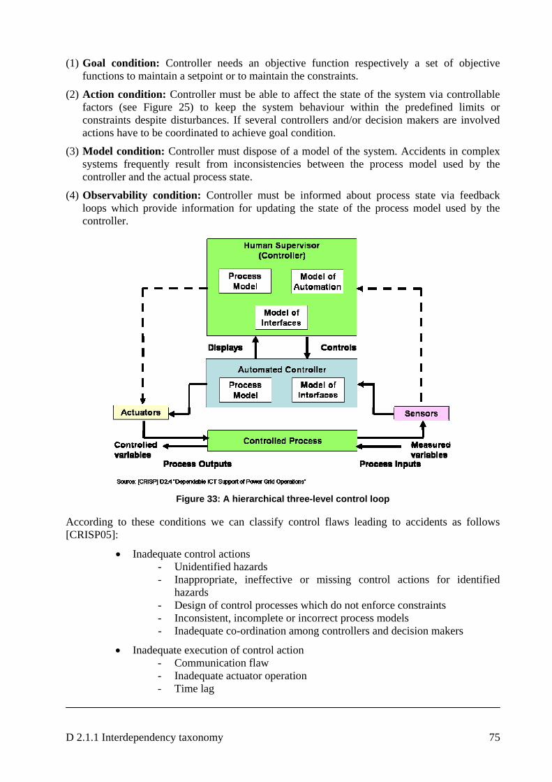
D 2.1.1 Interdependency taxonomy 75
(1) Goal condition: Controller needs an objective function respectively a set of objective functions to maintain a setpoint or to maintain the constraints.
(2) Action condition: Controller must be able to affect the state of the system via controllable factors (see Figure 25) to keep the system behaviour within the predefined limits or constraints despite disturbances. If several controllers and/or decision makers are involved actions have to be coordinated to achieve goal condition.
(3) Model condition: Controller must dispose of a model of the system. Accidents in complex systems frequently result from inconsistencies between the process model used by the controller and the actual process state.
(4) Observability condition: Controller must be informed about process state via feedback loops which provide information for updating the state of the process model used by the controller.
Figure 33: A hierarchical three-level control loop
According to these conditions we can classify control flaws leading to accidents as follows [CRISP05]:
• Inadequate control actions - Unidentified hazards - Inappropriate, ineffective or missing control actions for identified
hazards - Design of control processes which do not enforce constraints - Inconsistent, incomplete or incorrect process models - Inadequate co-ordination among controllers and decision makers
• Inadequate execution of control action - Communication flaw - Inadequate actuator operation - Time lag
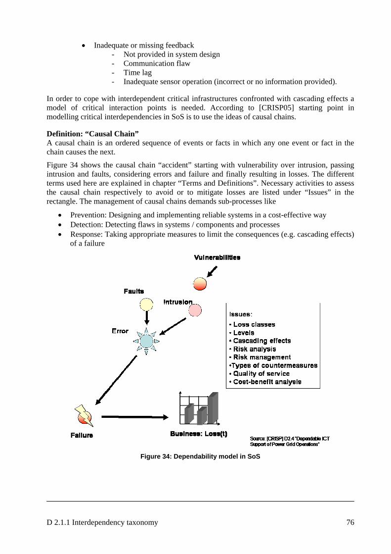
D 2.1.1 Interdependency taxonomy 76
• Inadequate or missing feedback - Not provided in system design - Communication flaw - Time lag - Inadequate sensor operation (incorrect or no information provided).
In order to cope with interdependent critical infrastructures confronted with cascading effects a model of critical interaction points is needed. According to [CRISP05] starting point in modelling critical interdependencies in SoS is to use the ideas of causal chains.
Definition: “Causal Chain” A causal chain is an ordered sequence of events or facts in which any one event or fact in the chain causes the next.
Figure 34 shows the causal chain “accident” starting with vulnerability over intrusion, passing intrusion and faults, considering errors and failure and finally resulting in losses. The different terms used here are explained in chapter “Terms and Definitions”. Necessary activities to assess the causal chain respectively to avoid or to mitigate losses are listed under “Issues” in the rectangle. The management of causal chains demands sub-processes like
• Prevention: Designing and implementing reliable systems in a cost-effective way • Detection: Detecting flaws in systems / components and processes • Response: Taking appropriate measures to limit the consequences (e.g. cascading effects)
of a failure
Figure 34: Dependability model in SoS
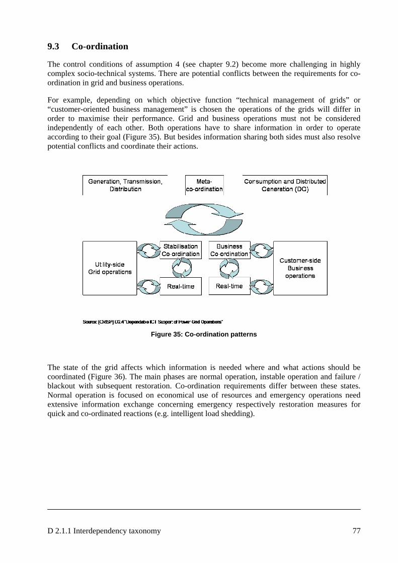
D 2.1.1 Interdependency taxonomy 77
9.3 Co-ordination
The control conditions of assumption 4 (see chapter 9.2) become more challenging in highly complex socio-technical systems. There are potential conflicts between the requirements for co-ordination in grid and business operations.
For example, depending on which objective function “technical management of grids” or “customer-oriented business management” is chosen the operations of the grids will differ in order to maximise their performance. Grid and business operations must not be considered independently of each other. Both operations have to share information in order to operate according to their goal (Figure 35). But besides information sharing both sides must also resolve potential conflicts and coordinate their actions.
Figure 35: Co-ordination patterns
The state of the grid affects which information is needed where and what actions should be coordinated (Figure 36). The main phases are normal operation, instable operation and failure / blackout with subsequent restoration. Co-ordination requirements differ between these states. Normal operation is focused on economical use of resources and emergency operations need extensive information exchange concerning emergency respectively restoration measures for quick and co-ordinated reactions (e.g. intelligent load shedding).

D 2.1.1 Interdependency taxonomy 78
Figure 36: Communication and co-ordination in different phases
In a failure state the network may be incommunicable and in the restoration phase wide area and cross-sector consensus is needed so that the system can be securely brought back into normal operation. System under normal operation is mainly controlled by business applications interfacing through electronic market. Competing system operators typically do not trust each other and share only limited information required to support the market and legislation. But emergency operations demand more information since the stability of the whole grid is more important than keeping back current information. It has to be possible to develop and implement suited MIT16 components for support of communication. MIT add-on components should be focused on co-ordination respectively control support between control centres for normal and instable states as well as for state of disruption of supply. That means, we have to define appropriate models and processes what implies that a set of policies has to be provided which allows to implement a unified model meeting the designed constraints. Requirements concerning MIT-components and MIT-add-on components are identified in [D1.4.3] and their architecture can be found in [D2.4.1] and [D2.4.2].
16 Middleware Improved Technology
D 2.1.1 Interdependency taxonomy 79
10. References
[AC03] ACIP consortium: Analysis and Assessment for Critical Infrastructure Protection (ACIP) final report. EU/IST, Brussels, Belgium, 2003; http://www.iabg.de/acip/
[AD06] Diu, Antonio 2006. Electric Infrastructure. Presentation in the IRRIIS Brainstorming, Scenario analysis. 9-10, March 2006. Nuremburg, Germany. 24 p.
[AE04] Autorità per l´energia elettrica e il gas: Report on the events of September 28th, 2003 culminating in the separation of the Italian power system from the other UCTE networks; Allegato A – delibera n. 61/04
[AWD06] Abele-Wigert, I; Dunn, M.: International CIIP Handbook; Center for Security Studies and Conflict Research at the Swiss Federal Institute of Technology (ETH) Zurich, Switzerland; 2006
[AGP04] Arun G. Phadke: Hidden failures in electric power systems; Int. J. Critical Infrastructures, Vol. 1, No. 1, 2004
[AVG04] Adrian V. Gheorghe: Risks, vulnerability and governance: a new landscape for critical infrastructures; Int. J. Critical Infrastructures, Vol. 1, No. 1, 2004
[BA04] Edward E. Balkovich, Robert H. Anderson: Critical infrastructures will remain vulnerable: neighbourhouds must fend for themselves”; Int. J. Critical Infrastructures, Vol. 1, No. 1, 2004
[BBB04] Theresa Brown, Walt Beyeler, Dianne Barton: Assessing infrastructure interdependencies: the challenge of risk analysis for complex adaptive systems; Int. J. Critical Infrastructures, Vol. 1, No. 1, 2004
[BN03] Bacher, R. and Näf, U: Report on the blackout in Italy on 28 September 3003; Swiss Federal Office of Energy (SFOE), November 2003
[BR04] Benoit Robert: A method for the study of cascading effects within lifeline networks; Int. J. Critical Infrastructures, Vol. 1, No. 1, 2004
[CEER05] Electricity Working Group “Quality of Supply Task Force”: Third Benchmarking Report on Quality of Electricity Supply 2005, issued by Council of European Energy Regulators
[CRISP05] EU Project CRISP, Deliverable “Dependable ICT Support of Power Grid Operations (http://crisp.ecn.nl/deliverables/D2.4.pdf)
[D1.1.1] IRRIIS Deliverable D1.1.1 „Report on Inventury“, 2006
[D1.1.3] IRRIIS Deliverable D1.1.3 “Report on knowledge elicitation and state of the art including LCCI requirements for ICT tools that will solve identified CIIP problems and identification of R&D gaps”, 2006
[D1.2.1] IRRIIS Deliverable D1.2.1 “Scenario Analysis”, 2006
[D1.2.2] IRRIIS Deliverable D1.2.2 “Risk Analysis”, 2006,
[D1.4.3] IRRIIS Deliverable D1.4.3 “Final document of MIT requirements”
[D2.4.1] IRRIIS Deliverable D2.4.1 “Interim design of MIT communication layer and LCCI interface”
D 2.1.1 Interdependency taxonomy 80
[D2.4.2] IRRIIS Deliverable D2.4.2 “Interim design of MIT add-on components”
[DPH02] Prof. Dr. Hans Dobbertin, Prof. Dr.-Ing. Christof Paar, Dipl.-Soz. Wiss. Markus Heitmann: Interdependenzen von Kritischen Infrastrukturen; EUROBITS, Horst-Görtz-Institut für IT-Sicherheit, Bochum, Oktober 2002, Version 1.0
[D76] Dörner, D.: Problemlösen als Informationsverarbeitung, Kohlhammer Verlag Stuttgart 1976
[EC03a] European Commission (2003a): Commission Decision of 11 November 2003 on establishing the European Regulators Group for Electricity and Gas, Brussels, 2003
[EC03b] European Commission (2003b): Directorate General for Energy and Transport, Energy infrastructures: increasing security of supply in the Union – new legislative rules proposed, memorandum, Information and Communication Unit of DG Energy and Transport, Brussels
[EC04c] European Commission (2004c), Directorate General for Energy and Transport: Guidelines on Transmission Tarification, Explorative Note, September 1.
[EP01] European Parliament (2001). Directive 2001/77/EC of the European Parliament and of the Council of 27 September 2001 on the promotion of electricity produced from renewable energy sources in the internal electricity market. Official Journal of the European Union , 2001, L 283, 33-40
[EP97] European Parliament (1997). Directive 96/92/EC of the European Parliament and of the Council of 19 December 1996 concerning common rules for the internal market in electricity. Official Journal of the European Union , 1997, L 27, 20-29
[ETH05] Markus Schläpfer, ETH Zurich: Comparative Case Study on Recent Blackouts; 3rd EAPC/PfP Workshop on Critical Infrastructure Protection and Civil Emergency Planning, Zurich, 22 – 24 September 2005; http://pforum.isn.ethz.ch/docs/10CD73FF-65B0-58E9-2AC4D106189121F4.pdf
[EU01] EU Commission. 2001. Green paper. Towards a European strategy for the security of energy supply. 105 p. (ISBN 92-894-0319-5.)
[EU03] DIRECTIVE 2003/54/EC OF THE EUROPEAN PARLIAMENT AND OF THE COUNCIL of 26 June 2003 concerning common rules for the internal market in electricity and repealing Directive 96/92/EC
[EU04] EU: Critical Infrastructure Protection in the fight against terrorism, COM(2004) 702 final. Communication from the Commission to the Council and the European Parliament, Brussels, 2004.
[EU05] EU Project CI2RCO: D1 – Common Understanding of CI2RCO-Basics, 21 June, 2005
[EW06] EWICS. 2006. Subgroup security, briefing paper: Electric power system cyber security: Power substation case study. European workshop on industrial computer systems. Technical committee 7: Reliability, safety, security. 29 p.
[GV04] Adrian V. Gheorghe; Dan V. Vamanu: Complexity induced vulnerability; Int. J. Critical Infrastructures, Vol. 1, No. 1, 2004
[HODW] John Hauer, Pacific Northwest National Laboratory Richland, Washington; Tom Overbye, University of Illinois at Urbana-Champaign Urbana Illinois; Jeff Dagle, Pacific
D 2.1.1 Interdependency taxonomy 81
Northwest National Laboratory; Steve Widergren, Pacific Northwest National Laboratory: “Advanced Transmission Technologies”
[IR06] IRRIIS “Description of Work”: https://bscw.sit.fraunhofer.de/bscw/bscw.cgi/d638083/IRRIIS_DoW_seventh_version.pdf
[JP] James Peerenboom: Infrastructure interdependencies: Overview of concepts and terminology; Infrastructure Assurance Center, Argonne National Laboratory, Argonne, IL 60439
[Lev04] Leveson, N.G. (2004). A new Accident Model for Engineering Safer Systems. Safety Science, Volume 42, Number 4, Elsevier, April 2004
[MQP04] L. Mili and Q. Qiu, A.G. Phadke: Risk assessment of catastrophic failures in electric power systems; Int. J. Critical Infrastructures, Vol. 1, No. 1, 2004
[NERC] NERC Disturbance Reports – North American Electric Reliability Council, New Jersey, 1984-1988. Available at: http://www.nerc.com/dawg/database.html (cited by [MQP04])
[NO06] North, M.J., N.T. Collier, and J.R. Vos, "Experiences Creating Three Implementations of the Repast Agent Modeling Toolkit," ACM Transactions on Modeling and Computer Simulation, Vol. 16, Issue 1, pp. 1-25, ACM, New York, New York, USA (January 2006)
[PFW01] James Peerenboom, Ronald Fisher, and Ronald Whitfield: Recovering from disruptions of interdependent critical infrastructures; Infrastructure Assurance Center, Argonne National Laboratory; Workshop on “Mitigating the Vulnerability of Critical Infrastructures to Catastrophic Failures” September 10-11, 2001 (www.pnwer.org/pris/presentations/RECOVERING%20FROM%20DISRUPTIONS%20OF%20INTERDEPENDENT.PDF)
[PG91] Probst, G.J.B./ Gomez,P: Vernetztes Denken – Ganzheitliches Führen in der Praxis; Gabler Verlag Wiesbaden, 1991
[RPK01] Steven M. Rinaldi, James P. Peerenboom, and Terrence K. Kelly: Identifying, Understanding, and Analyzing Critical Infrfastructure Interdependencies; IEEE Control Systems Magazine, December 2001
[R03] Roßnagel, A.: Sicherheit für Freiheit?; Nomos Verlagsgesellschaft Baden-Baden, 2003
[SESAM] http://www.simsesam.de/
[SUSTELNET] EU project (5th RTD Framework Programme, contract No. ENK5-CT2001-00577; www.sustelnet.net) : “Review of the role of ICT in network management and market operators”
[SWARM] http://www.swarm.org/wiki/Main_Page
[U] UNICON Management Systeme GmbH: GAMMA Das PC Werkzeug für Vernetztes Denken
[UCTE03] UCTE Report „Interim report of the investigation committee on the 28 September 2003 blackout in Italy“; UCTE Report – 27 October 2003
[UC04] U.S. – Canada Power System Outage Task Force: Final Report on the August 14, 2003 Blackout in the U.S. and Canada: Causes and Recommendations”; April 2004
[UP88] Ulrich, H./ Probst, G.J.B.: Anleitung zum ganzheitlichen Denken und Handeln, Bern und Stuttgart 1988
D 2.1.1 Interdependency taxonomy 82
[V00] Vester, F.: Die Kunst vernetzt zu denken: Ideen und Werkzeuge für einen neuen Umgang mit Komplexität, DVA Stuttgart, 2000 ISBN 3-421-05308-1
[VDE06] ETG-Task-Force Versorgungsqualität: VDE-Analyse “Versorgungsqualität im deutschen Stromversorgungssystem”, Februar 2006
[VH88] Vester, F.; von Hesler, A.: Sensitivitätsmodell; Umlandverband Frankfurt, 1988
[WS03] W. Schmitz: „M&S for Analysis of Critical Infrastructures”; Congress of the Gesellschaft für Informatik (GI) in Frankfurt a.M., 29.9. -2.10.03