Embed Size (px)
Citation preview
1 Copyright © 2021 by ASME
Advanced Mechanical Design, University of Rochester Final Design Report
Spring 2021
PUMPKIN LAUNCHING DEVICE WITH ROTATING TIRES
Alexander
Morgenthaler
Henri Pretorius
Max Friedman
Nick Pomianek
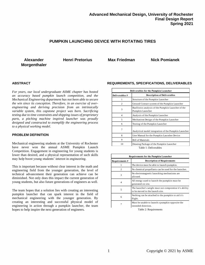
ABSTRACT
For years, our local undergraduate ASME chapter has hosted
an accuracy based pumpkin launch competition, and the
Mechanical Engineering department has not been able to secure
the win since its conception. Therefore, in an exercise of over-
engineering and deriving precision from an intrinsically
variable system, this capstone project was born. Sacrificing
testing due to time constraints and shipping issues of proprietary
parts, a pitching machine inspired launcher was proudly
designed and constructed to exemplify the engineering process
to a physical working model.
PROBLEM DEFINITION
Mechanical engineering students at the University of Rochester
have never won the annual ASME Pumpkin Launch
Competition. Engagement in engineering for young students is
lower than desired, and a physical representation of such skills
may help boost young students’ interest in engineering.
This is important because without clear interest in the math and
engineering field from the younger generation, the level of
technical advancement their generation can achieve can be
diminished. Not only does this impact the current generation of
young students, but also future generations of engineers as well.
The team hopes that a solution lies with creating an interesting
pumpkin launcher that can spark interest in the field of
mechanical engineering with the younger generation. By
creating an interesting and successful physical model of
engineering in action through a pumpkin launcher, the team
hopes to help inspire the next generation of engineers.
REQUIREMENTS, SPECIFICATIONS, DELIVERABLES
Table 1: Deliverables
Table 2: Requirements
Deliverables # Description of Deliverables
1 Structure of the Pumpkin Launcher
2 Ground Contact system of the Pumpkin Launcher
3Basllistics analysis of the Pumpkin Launcher of the
Pumpkin Launcher
4 Analysis of the Pumpkin Launcher
5 Mechanism Design of the Pumpkin Launcher
6 Testing of the Pumpkin Launcher
7Analytical model integration of the Pumpkin Launcher
8 User Manual for the Pumpkin Laucnher Device
9 Bill of Materials
10 Drawing Package of the Pumpkin Launcher
Deliverables for the Pumpkin Launcher
Requirements # Description of Requirements
1 The device must be able to launch pumpkin.
2 No chemical propellants can be used for the launcher.
3No electromagnetic launching mechanisms are
allowed.
4All energy used to launch the pumpkin must be
generated on site.
5The launcher's weight must not compromise it's ability
to be moved to the launch site.
6Nothing can be attached to the pumpkin to aid it's
flight.
7Must be unable to launch a pumpkin opposite the
intended direction.
Requirements for the Pumpkin Launcher
2 Copyright © 2021 by ASME
Table 3: Specifications
CONCEPTS
There were three designs considered for the future direction of
the project. All three designs incorporate a flywheel because of
the mechanical benefits it can provide such as energy storage
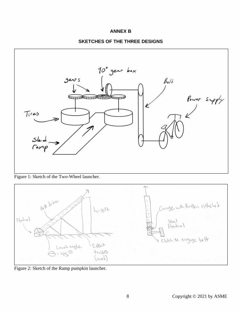
between shots. The first design, named ‘Two Wheels,’ uses two
rotating flywheels to accelerate and maintain speed for each
launch of the pumpkin. A sketch of the Two Wheel design can
be found in Annex B, Figure 1. The second design considered is
named the ‘Ramp.’ In this design there is a large steel flywheel
that will be rotating freely until the desired speed is reached. At
this time a trigger will engage a clutch that will engage a belt to
transfer the flywheel energy into the pumpkin. A sketch of the
Ramp design can be found under Annex B, Figure 2. The final
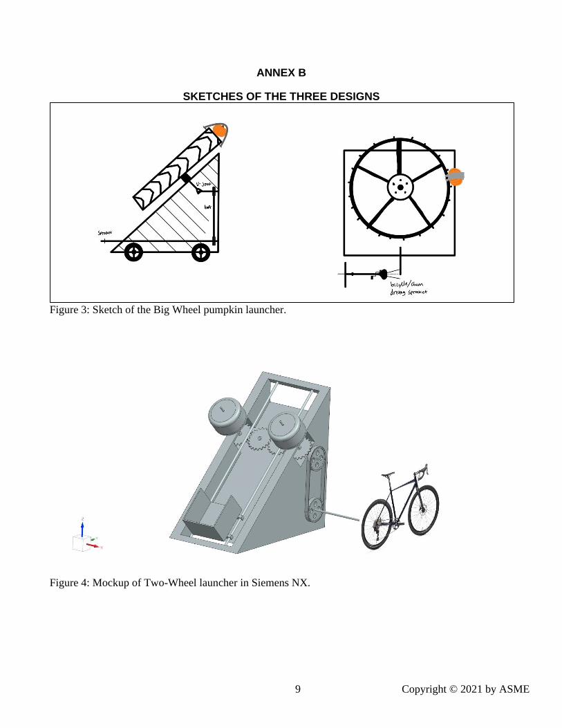
design considered is named ‘Big Wheel.’ In this design another
flywheel is used however this time the flywheel will be much
larger and be angled at 45º, with the pumpkin attached on the
edge. The speed of the flywheel will increase until the desired
angular velocity is achieved. at this point a pin will release the
pumpkin and launch it towards the desired location. A sketch of
the final design can be found in Annex B, Figure 3.
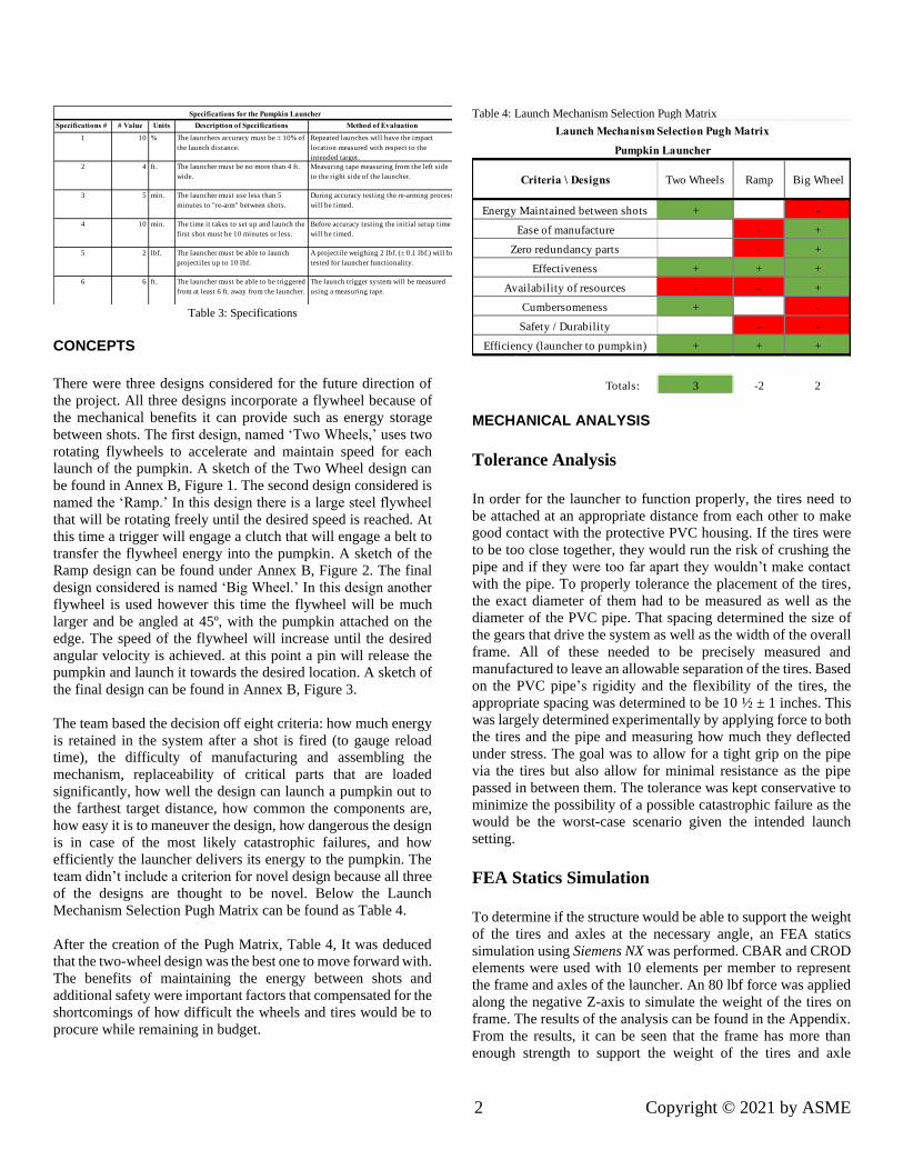
The team based the decision off eight criteria: how much energy
is retained in the system after a shot is fired (to gauge reload
time), the difficulty of manufacturing and assembling the
mechanism, replaceability of critical parts that are loaded
significantly, how well the design can launch a pumpkin out to
the farthest target distance, how common the components are,
how easy it is to maneuver the design, how dangerous the design
is in case of the most likely catastrophic failures, and how
efficiently the launcher delivers its energy to the pumpkin. The
team didn’t include a criterion for novel design because all three
of the designs are thought to be novel. Below the Launch
Mechanism Selection Pugh Matrix can be found as Table 4.
After the creation of the Pugh Matrix, Table 4, It was deduced
that the two-wheel design was the best one to move forward with.
The benefits of maintaining the energy between shots and
additional safety were important factors that compensated for the
shortcomings of how difficult the wheels and tires would be to
procure while remaining in budget.
Table 4: Launch Mechanism Selection Pugh Matrix
MECHANICAL ANALYSIS
Tolerance Analysis
In order for the launcher to function properly, the tires need to
be attached at an appropriate distance from each other to make
good contact with the protective PVC housing. If the tires were
to be too close together, they would run the risk of crushing the
pipe and if they were too far apart they wouldn’t make contact
with the pipe. To properly tolerance the placement of the tires,
the exact diameter of them had to be measured as well as the
diameter of the PVC pipe. That spacing determined the size of
the gears that drive the system as well as the width of the overall
frame. All of these needed to be precisely measured and
manufactured to leave an allowable separation of the tires. Based
on the PVC pipe’s rigidity and the flexibility of the tires, the
appropriate spacing was determined to be 10 ½ ± 1 inches. This
was largely determined experimentally by applying force to both
the tires and the pipe and measuring how much they deflected
under stress. The goal was to allow for a tight grip on the pipe
via the tires but also allow for minimal resistance as the pipe
passed in between them. The tolerance was kept conservative to
minimize the possibility of a possible catastrophic failure as the
would be the worst-case scenario given the intended launch
setting.
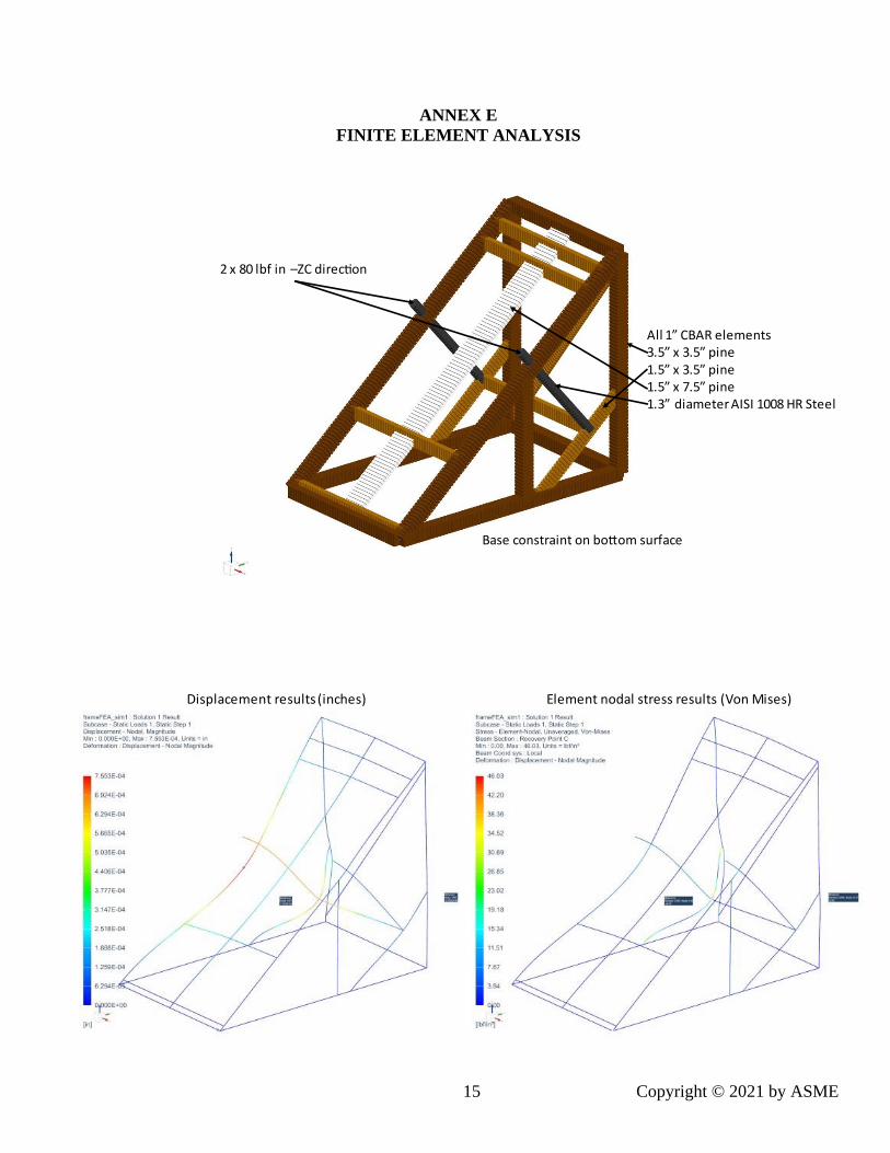
FEA Statics Simulation
To determine if the structure would be able to support the weight
of the tires and axles at the necessary angle, an FEA statics
simulation using Siemens NX was performed. CBAR and CROD
elements were used with 10 elements per member to represent
the frame and axles of the launcher. An 80 lbf force was applied
along the negative Z-axis to simulate the weight of the tires on
frame. The results of the analysis can be found in the Appendix.
From the results, it can be seen that the frame has more than
enough strength to support the weight of the tires and axle
Specifications # # Value Units Description of Specifications Method of Evaluation
1 10 % The launchers accuracy must be ± 10% of
the launch distance.
Repeated launches will have the impact
location measured with respect to the
intended target.
2 4 ft. The launcher must be no more than 4 ft.
wide.
Measuring tape measuring from the left side
to the right side of the launcher.
3 5 min. The launcher must use less than 5
minutes to "re-arm" between shots.
During accuracy testing the re-arming process
will be timed.
4 10 min. The time it takes to set up and launch the
first shot must be 10 minutes or less.
Before accuracy testing the initial setup time
will be timed.
5 2 lbf. The launcher must be able to launch
projectiles up to 10 lbf.
A projectile weighing 2 lbf. (± 0.1 lbf.) will be
tested for launcher functionality.
6 6 ft. The launcher must be able to be triggered
from at least 6 ft. away from the launcher.
The launch trigger system will be measured
using a measuring tape.
Specifications for the Pumpkin Launcher
+ -
- +
- +
+ + +
- - +
+ -
- -
+ + +
3 -2 2
Launch Mechanism Selection Pugh Matrix
Pumpkin Launcher
Totals:
Criteria \ Designs
Ease of manufacture
Zero redundancy parts
Effectiveness
Availability of resources
Cumbersomeness
Efficiency (launcher to pumpkin)
Safety / Durability
Energy Maintained between shots
Two Wheels Ramp Big Wheel
3 Copyright © 2021 by ASME
assembly with an estimated max stress of 46.03 psi. This is well
under the yield stress of American eastern white pine of 503 psi
[1].
Dynamics Calculations
By nature of the launcher’s design, the exit velocity of the
pumpkin can be throttled to achieve different travel distances. To
determine how fast the pumpkin needed to be going to reach
different distances, a Matlab script was written to solve for the
various initial conditions required. The dynamic model works off
of an ODE solver inside an optimization algorithm. By solving
the kinematic ODE for various speeds at the given conditions
and determining how far off the impact location is from the
target, the speed it takes to exactly hit the target is calculated.
The script takes into consideration the tail/ headwind and target
distance to calculate how fast the pumpkin needs to be launched.
The code for this script as well as the accompanying equations
can be found in the Appendix.
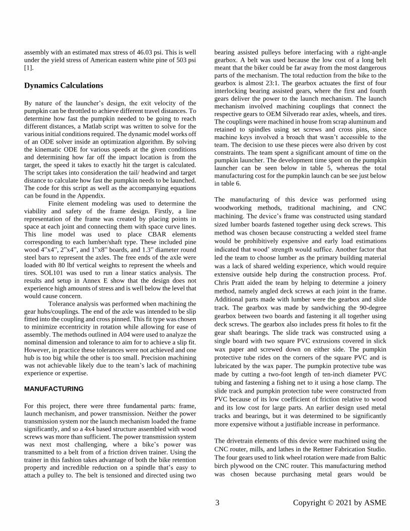
Finite element modeling was used to determine the
viability and safety of the frame design. Firstly, a line
representation of the frame was created by placing points in
space at each joint and connecting them with space curve lines.
This line model was used to place CBAR elements
corresponding to each lumber/shaft type. These included pine
wood 4”x4”, 2”x4”, and 1”x8” boards, and 1.3” diameter round
steel bars to represent the axles. The free ends of the axle were
loaded with 80 lbf vertical weights to represent the wheels and
tires. SOL101 was used to run a linear statics analysis. The
results and setup in Annex E show that the design does not
experience high amounts of stress and is well below the level that
would cause concern.
Tolerance analysis was performed when machining the
gear hubs/couplings. The end of the axle was intended to be slip
fitted into the coupling and cross pinned. This fit type was chosen
to minimize eccentricity in rotation while allowing for ease of
assembly. The methods outlined in A04 were used to analyze the
nominal dimension and tolerance to aim for to achieve a slip fit.
However, in practice these tolerances were not achieved and one
hub is too big while the other is too small. Precision machining
was not achievable likely due to the team’s lack of machining
experience or expertise.
MANUFACTURING
For this project, there were three fundamental parts: frame,
launch mechanism, and power transmission. Neither the power
transmission system nor the launch mechanism loaded the frame
significantly, and so a 4x4 based structure assembled with wood
screws was more than sufficient. The power transmission system
was next most challenging, where a bike’s power was
transmitted to a belt from of a friction driven trainer. Using the
trainer in this fashion takes advantage of both the bike retention
property and incredible reduction on a spindle that’s easy to
attach a pulley to. The belt is tensioned and directed using two
bearing assisted pulleys before interfacing with a right-angle
gearbox. A belt was used because the low cost of a long belt
meant that the biker could be far away from the most dangerous
parts of the mechanism. The total reduction from the bike to the
gearbox is almost 23:1. The gearbox actuates the first of four
interlocking bearing assisted gears, where the first and fourth
gears deliver the power to the launch mechanism. The launch
mechanism involved machining couplings that connect the
respective gears to OEM Silverado rear axles, wheels, and tires.
The couplings were machined in house from scrap aluminum and
retained to spindles using set screws and cross pins, since
machine keys involved a broach that wasn’t accessible to the
team. The decision to use these pieces were also driven by cost
constraints. The team spent a significant amount of time on the
pumpkin launcher. The development time spent on the pumpkin
launcher can be seen below in table 5, whereas the total
manufacturing cost for the pumpkin launch can be see just below
in table 6.
The manufacturing of this device was performed using
woodworking methods, traditional machining, and CNC
machining. The device’s frame was constructed using standard
sized lumber boards fastened together using deck screws. This
method was chosen because constructing a welded steel frame
would be prohibitively expensive and early load estimations
indicated that wood’ strength would suffice. Another factor that
led the team to choose lumber as the primary building material
was a lack of shared welding experience, which would require
extensive outside help during the construction process. Prof.
Chris Pratt aided the team by helping to determine a joinery
method, namely angled deck screws at each joint in the frame.
Additional parts made with lumber were the gearbox and slide
track. The gearbox was made by sandwiching the 90-degree
gearbox between two boards and fastening it all together using
deck screws. The gearbox also includes press fit holes to fit the
gear shaft bearings. The slide track was constructed using a
single board with two square PVC extrusions covered in slick
wax paper and screwed down on either side. The pumpkin
protective tube rides on the corners of the square PVC and is
lubricated by the wax paper. The pumpkin protective tube was
made by cutting a two-foot length of ten-inch diameter PVC
tubing and fastening a fishing net to it using a hose clamp. The
slide track and pumpkin protection tube were constructed from
PVC because of its low coefficient of friction relative to wood
and its low cost for large parts. An earlier design used metal
tracks and bearings, but it was determined to be significantly
more expensive without a justifiable increase in performance.
The drivetrain elements of this device were machined using the
CNC router, mills, and lathes in the Rettner Fabrication Studio.
The four gears used to link wheel rotation were made from Baltic
birch plywood on the CNC router. This manufacturing method
was chosen because purchasing metal gears would be
4 Copyright © 2021 by ASME
prohibitively expensive with lead times extending past the end
of the semester, and no UR machine shops have the capability to
manufacture large gears. The axles are fixed to their axle shafts
using wood glue and the axle shafts are simply one-inch diameter
pine wood dowels. The central gears are supported by two ball
bearings that are press fit into the gearbox. The two outer gears
are supported by the axle shafts and a ball bearing press fit into
the gearbox (the axle shafts are supported by needle roller
bearings press fit into the frame). Delrin washers, that were
turned on the lathe, are used to align the gears onto the same
plane. The wheels are connected to the drivetrain with single
piece rear axle shafts/hubs that were purchased online. The
choice to purchase these was made because the cost of raw
materials would be similar, but manufacturing time would be
significant. The axle shafts are fastened to their respective gears
using hubs machined from aluminum using a lathe and a mill.
The hubs were constructed by turning a coupling from a round
piece of bar stock, then attaching the flange with bolts that thread
into the coupling’s lower flat surface. This design was chosen to
reduce the amount of raw material needed and to work with the
available scrap in Rettner. The hub/coupling is fixed to the 90-
degree gearbox output shaft with a set screw and is supported by
a cross pin. Both hubs are affixed to their respective axles with a
cross pin. In order to cross pin the axle, a hole was milled through
the splined portion of the axle. This was done because the axles
are case hardened at the factory and machining any features more
complex than a hole would be beyond our abilities. The wood
gears are driven by a 90-degree gearbox that was purchased
online for the same reason the choice to make wood gears was
made. The input to the 90-degree gearbox is driven by a V-belt
pulley system that is connected to the drive shaft of a resistance
bike trainer. The pulley system was constructed by fastening V-
belt pulleys to the frame using bolts or dowels. The resistance
bike trainer was purchased used from Craigslist because it was
only $15 and there would be no feasible way to fabricate
something at a lower cost. The bike itself was found in Rettner
and borrowed for the semester. Manufacturing within the $1000
budget was a challenge, use of salvage and scrap was prioritized
and used parts were purchased whenever possible.
Table 5: Development Time for Pumpkin Launcher
Development Time
Group Member Time (Hr)
Alexander Morgenthaler 80.5
Nick Pomianek 81
Henri Protorius 72.5
Max Freidman 26.5
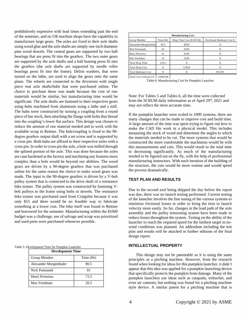
Table 6: Manufacturing Cost for Pumpkin Launcher
Note: For Tables 5 and Tables 6, all the time were collected
from the SCRUM daily information as of April 29th, 2021 and
may not reflect the most accurate time.
If the pumpkin launcher were scaled to 1000 systems, there are
many changes that can be made to improve cost and build time.
A large amount of the time was spent trying to figure out how to
make the CAD file work in a physical model. This includes
measuring the stock of wood and determine the angles to which
the materials needed to be cut. The more systems that would be
constructed the more comfortable the machinists would be with
this measurements and cuts. This would result to the total time
to decreasing significantly. As much of the manufacturing
needed to be figured out on the fly, with the help of professional
manufacturing instructors. With each iteration of the building of
the structure, the cuts would be more routine and would speed
the process dramatically.
TEST PLAN AND RESULTS
Due to the second axel being shipped the day before the report
was due, there was no launch testing performed. Current testing
of the launcher involves the fine tuning of the various systems to
minimize frictional losses in order to bring the tires to launch
velocity more easily. So far, changes in the load path of the axle
assembly and the pulley tensioning system have been made to
reduce losses throughout the system. Testing on the ability of the
launcher to reach the required speed for the farthest target in no-
wind conditions was planned. An addendum including the test
plan and results will be attached in further editions of the final
design report.
INTELLECTUAL PROPERTY
This design may not be patentable as it is using the same
principles as a pitching machine. However, from the research
found when looking for ideas for this pumpkin launcher, it didn’t
appear that this idea was applied for a pumpkin launching device
that specifically protects the pumpkin from damage. Many of the
pumpkin launchers use ideas such as catapults, trebuchet, and
even air cannons, but nothing was found for a pitching machine
style device. A similar patent for a pitching machine that is
Group Member Time (Hr) Shop Time Cost ($100/Hr) Purchased Hardware Cost $
Alexander Morgenthaler 49.5 4950 X
Nick Pomianek 43 4300 X
Henri Pretorius 41 4100 X
Max Freidman 25 2500 X
Total Shop Time 158.5 X X
Total Shop Cost X 15850 X
Total Hardware Cost X X 950.98
Total Cost of Project $ 16800.98
Manufacturing Cost
5 Copyright © 2021 by ASME
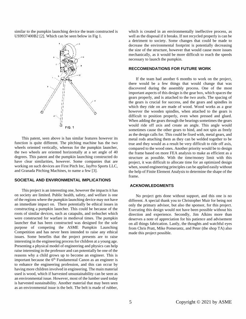
similar to the pumpkin launching device the team constructed is
US9937400B2 [2]. Which can be seen below in Fig 1.
This patent, seen above is has similar features however its
function is quite different. The pitching machine has the two
wheels oriented vertically, whereas for the pumpkin launcher,
the two wheels are oriented horizontally at a set angle of 40
degrees. This patent and the pumpkin launching constructed do
have clear similarities, however. Some companies that are
working on such devices are First Pitch Inc, JayPro Sports LLC,
and Granada Pitching Machines, to name a few [3].
SOCIETAL AND ENVIRONMENTAL IMPLICATIONS
This project is an interesting one, however the impacts it has
on society are limited. Public health, safety, and welfare is one
of the regions where the pumpkin launching device may not have
an immediate impact on. There potentially be ethical issues in
constructing a pumpkin launcher. This could be because of the
roots of similar devices, such as catapults, and trebuchet which
were constructed for warfare in medieval times. The pumpkin
launcher that has been constructed was designed for the sole
purpose of competing the ASME Pumpkin Launching
Competition and has never been intended to raise any ethical
issues. Some benefits that the project presents are to raise
interesting in the engineering process for children at a young age.
Presenting a physical model of engineering and physics can help
raise interesting in the professor and can potentially be one of the
reasons why a child grows up to become an engineer. This is
important because the 6th Fundamental Canon as an engineer is
to enhance the engineering profession, and this can occur by
having more children involved in engineering. The main material
used is wood, which if harvested unsustainability can be seen as
an environmental issue. However, most of the lumber used today
is harvested sustainability. Another material that may been seen
as an environmental issue is the belt. The belt is made of rubber,
which is created in an environmentally ineffective process, as
well as the disposal if it breaks. If not recycled properly is can be
a detriment to society. Some changes that could be made to
decrease the environmental footprint is potentially decreasing
the size of the structure, however that would cause more issues
mechanically, as it would be more difficult to reach the speeds
necessary to launch the pumpkin.
RECCOMENDATIONS FOR FUTURE WORK
If the team had another 6 months to work on the project,
there would be a few things that would change that was
discovered during the assembly process. One of the most
important aspects of this design is the gear box, which spaces the
gears properly, and is attached to the two axels. The spacing of
the gears is crucial for success, and the gears and spindles in
which they ride on are made of wood. Wood works as a gear
however the wooden spindles, when attached to the gears is
difficult to position properly, even when pressed and glued.
When adding the gears through the bearings sometimes the gears
would ride off axis and create an angle. This angle would
sometimes cause the other gears to bind, and not spin as freely
as the design calls for. This could be fixed with, metal gears, and
metal rods attaching them as they can be welded together to be
true and they would as a result be very difficult to ride off axis,
compared to the wood ones. Another priority would be to design
the frame based on more FEA analysis to make as efficient as a
structure as possible. With the time/money limit with this
project, it was difficult to allocate time for an optimized design
when, sound engineering principles can be applied easily without
the help of Finite Element Analysis to determine the shape of the
frame.
ACKNOWLEDGMENTS
No project gets done without support, and this one is no
different. A special thank you to Christopher Muir for being not
only the primary advisor, but also the sponsor, for this project.
Executing this design would not have been possible without his
direction and experience. Secondly, Jim Alkins more than
deserves a note of appreciation for his patience and advisement
on all things fabrication. Lastly, the thoughts and watchful eyes
from Chris Pratt, Mike Pomerantz, and Peter (the shop TA) also
made this project possible.
6 Copyright © 2021 by ASME
REFERENCES
[1] American Eastern White Pine
Wood, www.matweb.com/search/datasheet_print.aspx?matguid
=1bec7114d2524b63826044c3cc6c344c.
[2] “US9937400B2 - Automatic ball pitching machine.”
(n.d.). Google Patents, Google,
<https://patents.google.com/patent/US9937400B2/en> (Apr. 29,
2021).
[3] (n.d.). Pitching Machines,
<https://www.thomasnet.com/products/pitching-machines-
3304748-1.html> (Apr. 29, 2021).
7 Copyright © 2021 by ASME
ANNEX A
TREJECTORY AND ENERGY EQUATIONS
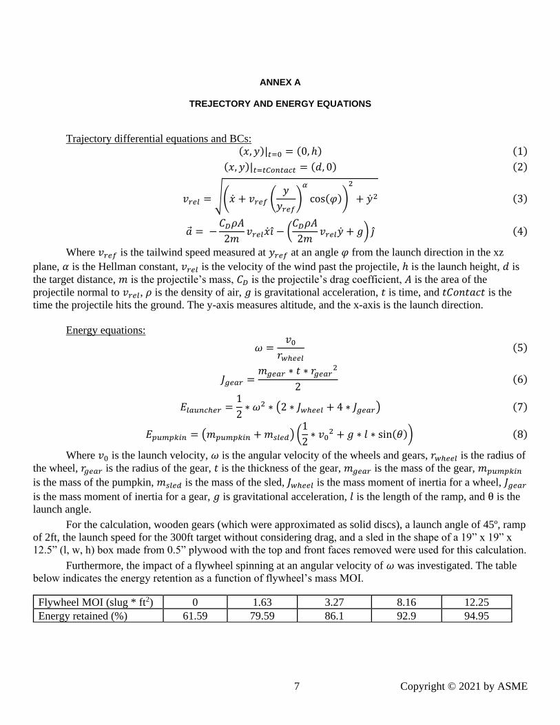
Trajectory differential equations and BCs: (𝑥, 𝑦)|𝑡=0 = (0, ℎ) (1)
(𝑥, 𝑦)|𝑡=𝑡𝐶𝑜𝑛𝑡𝑎𝑐𝑡 = (𝑑, 0) (2)
𝑣𝑟𝑒𝑙 = √(�̇� + 𝑣𝑟𝑒𝑓 (𝑦
𝑦𝑟𝑒𝑓)
𝛼
cos(𝜑))
2
+ �̇�2 (3)
�⃗� = −𝐶𝐷𝜌𝐴
2𝑚𝑣𝑟𝑒𝑙�̇�𝑖̂ − (
𝐶𝐷𝜌𝐴
2𝑚𝑣𝑟𝑒𝑙�̇� + 𝑔) 𝑗̂ (4)
Where 𝑣𝑟𝑒𝑓 is the tailwind speed measured at 𝑦𝑟𝑒𝑓 at an angle 𝜑 from the launch direction in the xz
plane, 𝛼 is the Hellman constant, 𝑣𝑟𝑒𝑙 is the velocity of the wind past the projectile, ℎ is the launch height, 𝑑 is
the target distance, 𝑚 is the projectile’s mass, 𝐶𝐷 is the projectile’s drag coefficient, 𝐴 is the area of the
projectile normal to 𝑣𝑟𝑒𝑙, 𝜌 is the density of air, 𝑔 is gravitational acceleration, 𝑡 is time, and 𝑡𝐶𝑜𝑛𝑡𝑎𝑐𝑡 is the
time the projectile hits the ground. The y-axis measures altitude, and the x-axis is the launch direction.
Energy equations:
𝜔 =𝑣0
𝑟𝑤ℎ𝑒𝑒𝑙
(5)
𝐽𝑔𝑒𝑎𝑟 =𝑚𝑔𝑒𝑎𝑟 ∗ 𝑡 ∗ 𝑟𝑔𝑒𝑎𝑟
2
2(6)
𝐸𝑙𝑎𝑢𝑛𝑐ℎ𝑒𝑟 =1
2∗ 𝜔2 ∗ (2 ∗ 𝐽𝑤ℎ𝑒𝑒𝑙 + 4 ∗ 𝐽𝑔𝑒𝑎𝑟) (7)
𝐸𝑝𝑢𝑚𝑝𝑘𝑖𝑛 = (𝑚𝑝𝑢𝑚𝑝𝑘𝑖𝑛 + 𝑚𝑠𝑙𝑒𝑑) (1
2∗ 𝑣0
2 + 𝑔 ∗ 𝑙 ∗ sin(𝜃)) (8)
Where 𝑣0 is the launch velocity, 𝜔 is the angular velocity of the wheels and gears, 𝑟𝑤ℎ𝑒𝑒𝑙 is the radius of
the wheel, 𝑟𝑔𝑒𝑎𝑟 is the radius of the gear, 𝑡 is the thickness of the gear, 𝑚𝑔𝑒𝑎𝑟 is the mass of the gear, 𝑚𝑝𝑢𝑚𝑝𝑘𝑖𝑛
is the mass of the pumpkin, 𝑚𝑠𝑙𝑒𝑑 is the mass of the sled, 𝐽𝑤ℎ𝑒𝑒𝑙 is the mass moment of inertia for a wheel, 𝐽𝑔𝑒𝑎𝑟
is the mass moment of inertia for a gear, 𝑔 is gravitational acceleration, 𝑙 is the length of the ramp, and θ is the
launch angle.
For the calculation, wooden gears (which were approximated as solid discs), a launch angle of 45º, ramp
of 2ft, the launch speed for the 300ft target without considering drag, and a sled in the shape of a 19” x 19” x
12.5” (l, w, h) box made from 0.5” plywood with the top and front faces removed were used for this calculation.
Furthermore, the impact of a flywheel spinning at an angular velocity of 𝜔 was investigated. The table
below indicates the energy retention as a function of flywheel’s mass MOI.
Flywheel MOI (slug * ft2) 0 1.63 3.27 8.16 12.25
Energy retained (%) 61.59 79.59 86.1 92.9 94.95
8 Copyright © 2021 by ASME
ANNEX B
SKETCHES OF THE THREE DESIGNS
Figure 1: Sketch of the Two-Wheel launcher.
Figure 2: Sketch of the Ramp pumpkin launcher.
9 Copyright © 2021 by ASME
ANNEX B
SKETCHES OF THE THREE DESIGNS
Figure 3: Sketch of the Big Wheel pumpkin launcher.
Figure 4: Mockup of Two-Wheel launcher in Siemens NX.
10 Copyright © 2021 by ASME
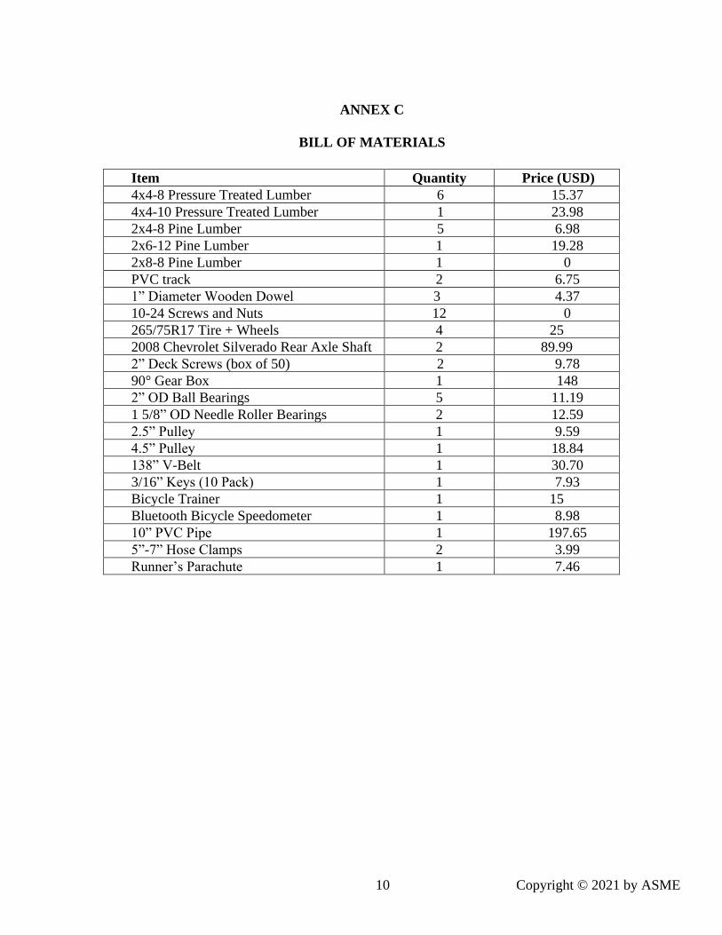
ANNEX C
BILL OF MATERIALS
Item Quantity Price (USD)
4x4-8 Pressure Treated Lumber 6 15.37
4x4-10 Pressure Treated Lumber 1 23.98
2x4-8 Pine Lumber 5 6.98
2x6-12 Pine Lumber 1 19.28
2x8-8 Pine Lumber 1 0
PVC track 2 6.75
1” Diameter Wooden Dowel 3 4.37
10-24 Screws and Nuts 12 0
265/75R17 Tire + Wheels 4 25
2008 Chevrolet Silverado Rear Axle Shaft 2 89.99
2” Deck Screws (box of 50) 2 9.78
90° Gear Box 1 148
2” OD Ball Bearings 5 11.19
1 5/8” OD Needle Roller Bearings 2 12.59
2.5” Pulley 1 9.59
4.5” Pulley 1 18.84
138” V-Belt 1 30.70
3/16” Keys (10 Pack) 1 7.93
Bicycle Trainer 1 15
Bluetooth Bicycle Speedometer 1 8.98
10” PVC Pipe 1 197.65
5”-7” Hose Clamps 2 3.99
Runner’s Parachute 1 7.46
11 Copyright © 2021 by ASME
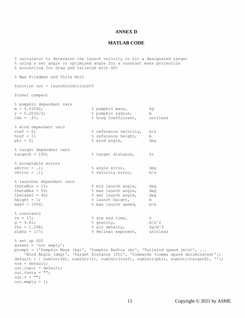
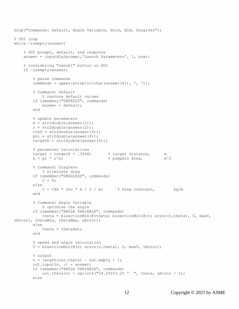
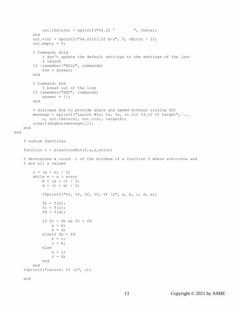
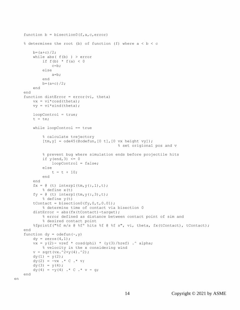
ANNEX D
MATLAB CODE
% calculator to determine the launch velocity to hit a designated target
% using a set angle or optimized angle for a constant mass projectile
% accounting for drag and tailwind with GUI
% Max Friedman and Chris Muir
function out = launchConditionsV3
format compact
% pumpkin dependant vars
m = 4.53592; % pumpkin mass, kg
r = 0.2032/2; % pumpkin radius, m
Cds = .47; % Drag Coefficient, unitless
% wind dependant vars
vref = 0; % reference velocity, m/s
href = 1; % reference height, m
phi = 0; % wind angle, deg
% target dependent vars
targetE = 100; % target distance, ft
% acceptable errors
aError = .1; % angle error, deg
vError = .1; % velocity error, m/s
% launcher dependent vars
thetaMin = 10; % min launch angle, deg
thetaMax = 50; % max launch angle, deg
thetaSet = 40; % set launch angle, deg
height = 1; % launch height, m
maxV = 1000; % max launch speed, m/s
% constants
te = 15; % sim end time, s
g = 9.81; % gravity, m/s^2
rho = 1.298; % air density, kg/m^3
alpha = 1/7; % Hellman exponent, unitless
% set up GUI
answer = 'not empty';
prompt = {'Pumpkin Mass (kg)', 'Pumpkin Radius (m)', 'Tailwind speed (m/s)', ...
'Wind Angle (deg)', 'Target Distance (ft)', 'Commands (comma space deliminated)'};
default = { num2str(m), num2str(r), num2str(vref), num2str(phi), num2str(targetE), ''};
now = default;
out.input = default;
out.theta = "";
out.v = "";
out.empty = 1;
12 Copyright © 2021 by ASME
disp("Commands: Default, Angle Variable, Hold, End, Dragless");
% GUI loop
while ~isempty(answer)
% GUI prompt, default, and responce
answer = inputdlg(prompt,'Launch Parameters', 1, now);
% considering "cancel" button on GUI
if ~isempty(answer)
% parse commands
commands = upper(strsplit(char(answer(6)), ', '));
% Command: Default
% restore default values
if ismember("DEFAULT", commands)
answer = default;
end
% update paramaters
m = str2double(answer(1));
r = str2double(answer(2));
vref = str2double(answer(3));
phi = str2double(answer(4));
targetE = str2double(answer(5));
% parameter calculations
target = targetE * .3048; % target distance, m
A = pi * r^2; % pumpkin Area, m^2
% Command: Dragless
% eliminate drag
if ismember("DRAGLESS", commands)
C = 0;
else
C = Cds * rho * A / 2 / m; % Drag constant, kg/m
end
% Command: Angle Variable
% optimize the angle
if ismember("ANGLE VARIABLE", commands)
theta = bisectionMin(@(theta) bisectionMin(@(v) error(v,theta), 0, maxV,
vError), thetaMin, thetaMax, aError);
else
theta = thetaSet;
end
% speed and angle calculation
V = bisectionMin(@(v) error(v,theta), 0, maxV, vError);
% output
n = length(out.theta) - out.empty + 1;
out.input(n, :) = answer;
if ismember("ANGLE VARIABLE", commands)
out.theta(n) = sprintf("%4.2f±%3.2f º ", theta, aError / 2);
else
13 Copyright © 2021 by ASME
out.theta(n) = sprintf("%4.2f º ", theta);
end
out.v(n) = sprintf("%4.2f±%3.2f m/s", V, vError / 2);
out.empty = 0;
% Command: Hold
% don't update the default settings to the settings of the last
% launch
if ~ismember("HOLD", commands)
now = answer;
end
% Command: End
% break out of the loop
if ismember("END", commands)
answer = {};
end
% dialogue box to provide angle and speed without closing GUI
message = sprintf("Launch #%u: %s, %s, to hit %4.1f ft target", ...
n, out.theta(n), out.v(n), targetE);
uiwait(msgbox(message),1);
end
end
% custom functions
function c = bisectionMin(f,a,e,error)
% determines x coord c of the minimum of a function f where a<b<c<d<e and
% are all x values
c = (a + e) / 2;
while e - a > error
b = (a + c) / 2;
d = (c + e) / 2;
%fprintf("%f, %f, %f, %f, %f \n", a, b, c, d, e);
fb = f(b);
fc = f(c);
fd = f(d);
if fc < fb && fc < fd
a = b;
e = d;
elseif fb < fd
e = c;
c = b;
else
a = c;
c = d;
end
end
%fprintf("return: %f \n", c);
end
14 Copyright © 2021 by ASME
function b = bisection0(f,a,c,error)
% determines the root (b) of function (f) where a < b < c
b=(a+c)/2;
while abs( f(b) ) > error
if f(b) * f(a) < 0
c=b;
else
a=b;
end
b=(a+c)/2;
end
end
function distError = error(vi, theta)
vx = vi*cosd(theta);
vy = vi*sind(theta);
loopControl = true;
t = te;
while loopControl == true
% calculate trejectory
[tm,y] = ode45(@odefun,[0 t],[0 vx height vy]);
% set origional pos and v
% prevent bug where simulation ends before projectile hits
if y(end,3) <= 0
loopControl = false;
else
t = t + 10;
end
end
fx = @ (t) interp1(tm,y(:,1),t);
% define x(t)
fy = @ (t) interp1(tm,y(:,3),t);
% define y(t)
tContact = bisection0(fy,0,t,0.01);
% determine time of contact via bisection 0
distError = abs(fx(tContact)-target);
% error defined as distance between contact point of sim and
% desired contact point
%fprintf("%f m/s @ %fº hits %f @ %f s", vi, theta, fx(tContact), tContact);
end
function dy = odefun(~,y)
dy = zeros(4,1);
vx = y(2)- vref * cosd(phi) * (y(3)/href) .^ alpha;
% velocity in the x considering wind
v = sqrt(vx.^2+y(4).^2);
dy(1) = y(2);
dy(2) = -vx .* C .* v;
dy(3) = y(4);
dy(4) = -y(4) .* C .* v - g;
end
en
15 Copyright © 2021 by ASME
ANNEX E
FINITE ELEMENT ANALYSIS