Embed Size (px)
Citation preview
Delft University of Technology
Numerical simulation of impact noise generated at the railway insulated joint
Yang, Z; Rahimi, S; Li, Z; Dollevoet, RPBJ
Publication date2014Document VersionAccepted author manuscriptPublished inProceedings of ISMA 2014 - International Conference on Noise and Vibration Engineering and USD 2014 -International Conference on Uncertainty in Structural Dynamics
Citation (APA)Yang, Z., Rahimi, S., Li, Z., & Dollevoet, RPBJ. (2014). Numerical simulation of impact noise generated atthe railway insulated joint. In P. Sas, H. Denayer, & D. Moens (Eds.), Proceedings of ISMA 2014 -International Conference on Noise and Vibration Engineering and USD 2014 - International Conference onUncertainty in Structural Dynamics (pp. 3583-3594). Katholieke Universiteit Leuven Department ofMechanical Engineering.Important noteTo cite this publication, please use the final published version (if applicable).Please check the document version above.
CopyrightOther than for strictly personal use, it is not permitted to download, forward or distribute the text or part of it, without the consentof the author(s) and/or copyright holder(s), unless the work is under an open content license such as Creative Commons.
Takedown policyPlease contact us and provide details if you believe this document breaches copyrights.We will remove access to the work immediately and investigate your claim.
This work is downloaded from Delft University of Technology.For technical reasons the number of authors shown on this cover page is limited to a maximum of 10.

Numerical simulation of impact noise generated at the railway insulated joint
Z. Yang 1, Z. Li
1 S. Rahimi
1, R.P.B.J. Dollevoet
1
1 Delft University of Technology, Section of Railway Engineering
Stevinweg 1, 2628 CN, Delft, the Netherlands
e-mail: [email protected]
Abstract This paper presents a full finite element (FE) model of wheel-track interaction to study the wheel-rail
impact noise excited by an insulated joint (IJ). The integration is performed in the time domain with an
explicit central difference scheme. The vibratory behaviour of the track and wheel model are respectively
validated with hammer test and Axle Box Acceleration (ABA) measurement. By making use of the
calculated velocities and pressures on the vibrating surfaces, the boundary element method (BEM) based
on Helmholtz equation is adopted to transform the vibrations of the wheel-track into acoustic signals. The
decay rate of impact noise at different frequency bands during propagation are analysed. The predictions
of total impact noise radiation and the noise contributions of different track components are in good
agreement with results reported in the literature, while the effective frequency range is successfully
extended from 5 kHz to 10 kHz.
1 Introduction
Due to the significant geometric and material discontinuity, IJ is considered as one of the weakest part of
the track structure and an important excitation source of impact noise. When a train runs over an IJ, wheel-
rail impact inevitably happens and consequently the ‘clickety-clack’ impact noise is generated and emitted.
An early comprehensive study on impact noise was published by Vér et al. in 1976 [1], before which the
studies focused on test and were largely qualitative. Vér et al. established an analytical model and defined
geometric and dynamic variables which make contributions to impact noise generation by analysing the
noise initiated at different types of discontinuities such as rail joints, frogs, switches, and wheel flats.
Because of the limited modelling approaches and computing resources at that time, the analytical model
was simple and failed to calculate the time history of impact force, let alone the spectral distribution of
impact noise. In reviewing the prior work, Remington [2] introduced the models and method of Newton
and Clark for contact force calculation [3] into analysis of impact noise to tackle non-linear contact
problem, pointing out a new direction for impact noise study. In addition, the geometric discontinuities of
the rail and wheel surfaces were replaced with an average roughness spectrum in frequency domain as the
excitation inputs for the calculation of impact vibration and noise. Wu and Thompson in [4] employed a
time-domain analytical contact model to calculate the impact force between wheel and rail under non-
linear contact conditions, and then, employing a linear approximation method, converted the impact force
into force spectrum in frequency domain and further into an equivalent roughness spectrum also in
frequency domain. On the basis of TWINS [5], the processed roughness spectrum was directly applied as
inputs and the impact noise results could be obtained. This hybrid method managed to solve the problem
of non-linearity, but due to the simplification of the contact model, the analysing frequency was limited to
5 kHz. A study by Pieringer et al. also showed that without consideration of the changes in contact
stiffness due to the realistic geometry at the discontinuities, simplified analytical model failed to reach a
sufficiently accurate prediction [6]. On the basis of Wu’s hybrid method, a more complicated numerical
finite element (FE) track model was developed in [7] to predict the impact noise track system and excited

by wheel flat, but the simplification of the wheel as a rigid mass still caused deviations especially at high
frequency.
Instead of using simplified analytical models of wheel and track, and the assumption of Hertzian or non-
Hertzian spring contact, Yang et al. presented a transient finite element wheel-track interaction model to
predict the impact noise generated by squat [8]. The wheel, the rail and the sleepers are modelled with
finite elements in three dimensions, where necessary and appropriate. Realistic contact geometry,
including 3D geometric irregularities in the contact surfaces is considered. The integration is performed in
the time domain with an explicit central difference scheme. By making use of the calculated velocities and
pressures of the vibrating surfaces, the boundary element method (BEM) based on Helmholtz equation is
adopted to transfer the vibration of the railway system into acoustic signal, extending the prediction range
of frequency of impact noise to 10 kHz.
By applying an approach similar to that of [8], a wheel-rail impact at an insulated joint (IJ) is modelled in
this paper. Compared with the squat excitation model, the structural and geometric discontinuity of the IJ
makes the track model developed in this paper more complex. In addition, the IJ excitation model
optimised the boundary conditions and mesh schemes of wheel and rail. The inertance frequency response
function of the track model and the dynamic vibrating response of the wheel model are respectively
validated by hammer test and Axle Box Acceleration (ABA) measurement. The impact noise emission and
the contributions of different track components to the total noise are analysed in the end.
2 FE model
2.1 The numerical model
A typical IJ of Dutch railway is selected in the track from Eindhoven to Weert as the modelling objective.
The in-situ condition of the IJ and the corresponding time-domain FE wheel-rail interaction model are
respectively shown in Fig. 1 and Fig. 2. To reduce the model size, a half-side track and a half wheel set
with sprung mass of the car body and the bogie are considered. Since the value of elastic modulus of the
insulation layer is much lower than that of the rail, the insulation layer between the two rail ends can be
omitted in the model and simplified as a gap. The IJ including fishplates, 4 pairs of bolts and a 6 mm
realistic geometrical gap is modelled in the middle of the 10 meter half-side track model. 9 sleeper spans
extend from IJ to each end of the track. According to the in-situ condition, the rail is UIC54 with an
inclination of 1:40. Non-reflective boundary conditions are applied at rail ends to prevent artificial stress
wave reflections generated at the model boundaries. The wheel geometry corresponds to that of a
passenger car of the Dutch railway with a radius of 0.46 meter. The symmetric boundary condition is
applied at the inner side of wheel axle and the outer end of the axle is free. The wheel, the rail, the
fishplates of the IJ and the sleepers are modelled with 8-node solid elements. In order to achieve a high
accuracy of the solution with a reasonable model size, non-uniform meshing scheme is used. The mesh
size around the initial position of the wheel-rail contact and the insulated joint area is 1 mm. The lumped
mass of the car body and bogie are modelled as 8 mass elements, connected to the wheelset by the primary
suspension of the vehicle with parallel linear springs and viscous dampers. The two neighbouring timber
sleepers beneath the IJ with baseplate fastening system and the concrete sleepers elsewhere with Vossloh
fastening system (Fig. 1) are differentiated by material models and spring/damper parameters. Bolts are
simplified as 4 pairs of oppositely-oriented force loads, pressing the fishplates on the web of rails. Since
the substructure has little influence on the high-frequency dynamic impact studied in this paper, each
sleeper only contains 12 solid elements and the ballast is simplified as vertical spring and damper elements
with the displacements constrained in lateral and longitudinal directions. The parameters used in the
model are listed in table 1. Most of them were taken from [9].

Figure 1: Modelling objective
Figure 2: FE Wheel-IJ Interaction Model
parameters values parameters values
Wheel diameter 0.92 m Wheel,
rail
material
Young’s modulus 210 GPa
Sprung mass 8000 kg Poisson’s ratio 0.3
Sleeper distance 0.6 m Density 7800 kg/m3
Primary
suspension
Stiffness 1.15 MN/m Yield stress 0.5 GPa
Damping 2500 Ns/m Tangent modulus 21 GPa
Baseplate
fastening
Stiffness 1944 MN/m Timber
sleeper
material
Young’s modulus 20 GPa
Damping 67440 Ns/m Poisson’s ratio 0.3
Vossloh
fastening
Stiffness 1300 MN/m Density 1300 kg/m3
Damping 45000 Ns/m Concrete
sleeper
material
Young’s modulus 38.4 GPa
Ballast
Stiffness 45 MN/m Poisson’s ratio 0.2
Damping 32000 Ns/m Density 2520 kg/m3
Table 1: The values of parameters in the model
Rolling Direction

To apply the real geometry to the surface of the rails at the IJ for the impact simulation, the longitudinal-
vertical rail profile at the IJ was measured with RAILPROF [10]. Since the RAILPROF measures the
longitudinal-vertical rail profile along the centre line of the rail, while the maximum deviation of the
vertical irregularity probably occurs off the centre line as shown in Fig. 3, modification is made for a more
realistic shape of IJ in the model. Fig. 4 shows the surfaces of the IJ model before and after applying the
measured profile.
Figure 3: Irregularity at rail surfaces around IJ
(a) ideal geometry at IJ (b) relistic geometry at IJ
Figure 4: Applying the realistic geometry to IJ (size of irregularity exaggerated)
The integration is performed in the time domain with an explicit central difference scheme. Very small
time step (4.9e-8 s) is employed for the model to meet Courant stability condition [11]. This effectively
guarantees that high frequency dynamic effect up to 10 kHz is reproduced. In the transient dynamic
simulation, a dynamic relaxation is first employed to make the wheel-track system reach an equilibrium
state under gravity. The initial position of wheel model is at 1.2 m (2 sleeper spans) away from the IJ (as
shown in Fig. 2). The movements of the wheel in both rotation and forward translation are applied as the
initial conditions. The wheel is subsequently set to roll along the rail from the initial position toward the
IJ. The effects of transient wheel rotation can be included inherently.
2.2 Model validation
Due to limitation on track access, the in-situ measurement of rail vibration and noise radiation have not yet
been performed. The properties of the track model and the dynamic response of the wheel model are
respectively validated with hammer test and Axle Box Acceleration (ABA) measurement.
2.2.1 Validation of track Inertance
The vibratory behaviour of the track model is validated with an in-situ hammer test. The hammer test was
performed at the selected IJ to obtain the experimental inertance of the track. A Brüel & Kjær 8206

hammer with a hard metal tip was used to generate a narrow band pulse. The input force spectrum
determines that the maximum valid frequency of the measured signals cannot be over 5 kHz. The
locations of the pulse load and the measurement of the rail vertical acceleration are at the rail head above
the sleeper just after the IJ.
Receptance of the track model was calculated by employing a harmonic analysis. The wheel was removed
from the model during the harmonic analysis. Under the harmonic excitation forces with constant
amplitude but varying frequencies from 10 Hz to 5 kHz at a step of 10Hz, the nodal displacements of the
FE track model can be obtained. Since the experimental response was obtained in terms of acceleration,
equation (1) is adopted to convert the calculated track receptance into simulation inertance for
comparison.
𝐻𝑎𝑓(𝑓) = (2𝜋𝑓)2 ∗ 𝐻𝑥𝑓(𝑓) (1)
Where Haf (f) and Hxf (f) are respectively inertance and receptance frequency response functions of the
track structure with the argument of frequency f . After the conversion, the calculated inertance of the
track is compared in Fig. 5 with the experimental inertance from the hammer test. It can be seen that, in
the frequency range higher than 500 Hz, the tendency and resonant behaviour of numerical inertance are
basically in accordance with the experimental inertance; while below 500 Hz, some sleeper-related low
frequency modes cannot be reproduced by the model, which could result from the simplification of sleeper
and ballast model. Since the main research objective of this paper is the high frequency impact noise,
whose dominant frequency range is over 1 kHz, this deviation at the lower end of the frequency range can
be tolerated for the dynamic and acoustic calculation.
Figure 5: Comparison of inertance of track at IJ
2.2.2 Axle Box Acceleration (ABA)
The calculated vibration acceleration of the wheel are validated by measured axle box accelerations (ABA)
[12]. ABA measurements were carried out twice at the selected IJ in September 2011 and march 2014,
respectively. The rail was ground just before the second measurement. During the two measurements, the
traveling speed of measuring train was kept around 100km/h when passing over the IJ area, the same with
the wheel rolling speed applied in the transient analysis. The vertical vibrations of both leading and
trailing axles were measured each time.
In order to see the tendencies and differences of the simulated and measured vibration results clearly, their
2 kHz low-pass filtered time history signals are plotted in Fig. 6 (a). As shown in the figure, the simulation
result has a good agreement with the measured results in the time domain. The positions of the peaks and
dips, as well as the attenuation trends of simulated and measured signals show basically the same pace
with each other. The differences can be attributed to the differences between the parameters used for the

model and the actual values in the track. In the frequency domain, the comparison of one third octave band
spectra in Fig. 6 (b) indicates that the calculated wheel acceleration is largely in agreement with the
measured results in the whole analysed frequency range. Specifically, the simulation signal in the low
frequency range is closer to the results from measurement 2. It is found that although the three peaks at
centre frequency bands of 1250 Hz, 2500 Hz and 4000Hz also exist in the vibration signals of
measurement 2, their values are significantly reduced compared with the results of measurement 1 and the
simulation signal. This is probably because the short wave irregularities of track which can excite high
frequency wheel vibration was decreased by grinding. Another explanation can be that the high frequency
vibration contents in this range were damped to certain extent by the bearings between wheel and axle,
while the lower frequency components could be conserved during the vibrating energy transfer from
wheel to axle box.
(a) time histories (b) one third octave spectra
Figure 6: Comparison of simulated wheel vibration and measured ABA
The wavelet power spectrum (WPS) indicates the energy distribution of a signal regarding both frequency
components and space distribution in a frequency range concerned. The WPS of the simulated wheel
vibration and the measured ABA are compared in the same scale in Fig. 7. To emphasis the main energy
parts and make the comparison clearly, only the frequency range below 5 kHz is plotted. It can be noticed
that in both the simulation and the measurement results, the energy concentrations take place just at the IJ
position and the dominant frequency focuses on about 500 Hz. For each measurement, the WPS at the
leading axle looks very similar to that at the trailing axle, but difference exists between the two
measurements. There exist obviously some high frequency contents in the WPS of measurement 1,
performed before rail grinding. Although less prominent than the dominant frequency contents, subtle
energy concentrations are noticeable at high frequency range around the IJ position in the WPS of
simulation and measurement 1, which indicates that the high frequency contents of wheel impact vibration
over IJ can reach up to 5 kHz or even higher. Since the same scale is applied for each WPS, the energy
value can be reflected by the area of energy concentration spot. By comparing the energy magnitudes of
WPS in one measurement, it can be found that the energy value of impact vibration from the trailing axle
is higher than that from the leading axle. The reason of this phenomenon will be further studied in future;
While compering the energy value from two different measurements, it seems that although rail grinding
was performed just before the measurement 2, the impact energy in the frequency range below 1 kHz is
still significant higher than that from measurement 1, which could be probably due to the deterioration of
substructures.

(a) simulation result
(b) measurement 1 leading axle (c) measurement 1 trailing axle
(d) measurement 2 leading axle (e) measurement 2 trailing axle
Figure 7: WPS of simulated wheel vibration and measured ABA
3 Impact noise reproduction
3.1 Boundary element method for noise radiation
After the validation of FE model, the Boundary Element method [13] is employed to transform the
vibration of the wheel and rail into acoustic radiation. In this case, a boundary surface enclosing a volume
(rail or wheel) is surrounded by an ideal and homogeneous fluid medium (air). In the frequency domain,

the acoustic wave propagation in an ideal fluid is governed by Helmholtz equation, which can be
discretized into a linear equation system by meshing the vibration surface of rail and wheel. Because of
the non-linear character of impact problem, the transient vibration response of track structural is computed
in the time domain. Through the Fast Fourier Transform, velocities on the surface of the structure are
converted into a frequency response, which can be further taken as boundary conditions for the BEM. This
frequency-domain method allows the calculation of sound pressure at any observation point of the
acoustic domain.
3.2 Noise propagation and contribution
Relying on the FE Model and the noise calculation method described above, the impact noise emission of
the modelled wheel-rail system were obtained. The distribution of receivers employed to collect the
acoustic signals generated by the track system is shown in Fig. 8. Taking in-situ measurement scenario
into consideration, the far-field receivers are placed at the same height as the wheel axle (0.6 m) to reduce
the ground reflection influence and perpendicular to the wheel web plane with distances of 1.5 m, 3 m and
6 m respectively. The near-field receiver is located at 0.03m (an approximation to 0 m) from the fishplate.
Figure 8: Placement of sound receivers
On the basis of the BEM, the vibrating rail, wheel and sleepers can be regarded as the sources of acoustic
emission. One third octave spectra of the total impact noise and the noise emission contributed by the rail
at each observation point are shown in Fig. 9 (a) and Fig. 9 (b) respectively. In the spectra of the total
impact noise, it shows four main frequency bands at around 600 Hz, 2 kHz, 3 kHz and 6 kHz. Among
them, the peaks of spectra at centre frequency of 630 Hz and 3 kHz are more predominant. From the gap
widths between spectra collected by different observation point, the decay rate of noise in the analysing
frequency range during propagation from near-field observation point to far-field ones can be determined.
Fig. 9 (a) shows that the predicted impact noise in the frequency range between 800 Hz and 3 kHz decays
less significantly than in the other frequency ranges, which also implies that the impact noise in the
frequency range of 800 Hz- 3 kHz is more likely to be transmitted as the noise pollution and required an
extra attention and prevention. The peak of one third octave spectrum at 6.3 kHz disappears when the
propagation distance is over 3m, which indicates that the near-field observation point is necessary when
the high-frequency content of impact noise is required to be captured in the test. For the noise contributed
by the rail, the common dominant frequencies of both near-field signal and far-field signals are around 2
kHz and 3 kHz. The one-third octave curves of sound collected by 0 m observation point also presents a
peak at 6.3 kHz, which dies away during propagation. Since previous studies on impact noise never
extended the analysing frequency range to more than 5 kHz, measurements are required for validation of
these results.

(a) total impact noise (b) noise radiated by the rail
Figure 9: One-third octave of impact noise
A good agreement can be found in Fig. 10 when comparing the results calculated in this paper with the
experimental and prediction results in literature [14], which also works on impact noise generation over IJ.
In Fig. 10 (a), two obvious peaks of one third octave spectrum at around 600 Hz and 3 kHz correspond
well with the testing and calculation results in the literature, while the analysed frequency in this paper is
extended to 10 kHz. The impact noise shown in Fig. 10 (a) was calculated at the observation point of 1.5
m, while the testing noise shown in Fig. 10 (b) was measured at a distance of 1.3 m from rail (2 m from
track centre). Since the traveling speed of testing train in the literature was only 35 km/h, much slower
than the simulation speed of 100 km/h used in this paper, the sound pressure levels (SPL) of impact noise
have significant difference. Another difference from the literature results is the impact noise contribution
of sleepers. The noise radiated by sleepers was predicted to devote more in the frequency range below
1kHz in the literature than that predicted in this paper. One possibility could be that the mesh size of
sleeper model in this paper was not sufficiently small for noise calculation by BEM.
(a) Results calculated in this paper (b) Results estimated in [14]
―, measurement, ―, total (estimated), -·-, sleeper, ···, rail, - -, wheel.
Figure 10: Noise contribution
4 Conclusion and Future work
A full finite element wheel-track interaction model is developed in this paper to study the wheel-rail
impact noise excited by an insulated joint. The properties of the track model and the vibration response of
the wheel model are respectively validated with hammer test and measurement of axle box acceleration.
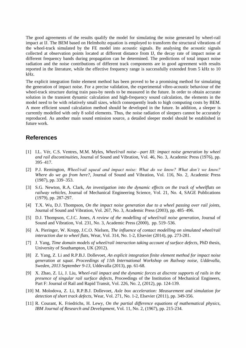
The good agreements of the results qualify the model for simulating the noise generated by wheel-rail
impact at IJ. The BEM based on Helmholtz equation is employed to transform the structural vibrations of
the wheel-track simulated by the FE model into acoustic signals. By analysing the acoustic signals
collected at observation points located at different distance from IJ, the decay rate of impact noise at
different frequency bands during propagation can be determined. The predictions of total impact noise
radiation and the noise contributions of different track components are in good agreement with results
reported in the literature, while the effective frequency range is successfully extended from 5 kHz to 10
kHz.
The explicit integration finite element method has been proved to be a promising method for simulating
the generation of impact noise. For a precise validation, the experimental vibro-acoustic behaviour of the
wheel-track structure during train pass-by needs to be measured in the future. In order to obtain accurate
solution in the transient dynamic calculation and high-frequency sound calculation, the elements in the
model need to be with relatively small sizes, which consequently leads to high computing costs by BEM.
A more efficient sound calculation method should be developed in the future. In addition, a sleeper is
currently modelled with only 8 solid elements. Thus, the noise radiation of sleepers cannot be accurately
reproduced. As another main sound emission source, a detailed sleeper model should be established in
future work.
References
[1] I.L. Vér, C.S. Ventres, M.M. Myles, Wheel/rail noise—part III: impact noise generation by wheel
and rail discontinuities, Journal of Sound and Vibration, Vol. 46, No. 3, Academic Press (1976), pp.
395–417.
[2] P.J. Remington, Wheel/rail squeal and impact noise: What do we know? What don’t we know?
Where do we go from here?, Journal of Sound and Vibration, Vol. 116, No. 2, Academic Press
(1987), pp. 339–353.
[3] S.G. Newton, R.A. Clark, An investigation into the dynamic effects on the track of wheelflats on
railway vehicles, Journal of Mechanical Engineering Science, Vol. 21, No. 4, SAGE Publications
(1979), pp. 287-297.
[4] T.X. Wu, D.J. Thompson, On the impact noise generation due to a wheel passing over rail joints,
Journal of Sound and Vibration, Vol. 267, No. 3, Academic Press (2003), pp. 485–496.
[5] D.J. Thompson, C.J.C. Jones, A review of the modelling of wheel/rail noise generation, Journal of
Sound and Vibration, Vol. 231, No. 3, Academic Press (2000), pp. 519–536.
[6] A. Pieringer, W. Kropp, J.C.O. Nielsen, The influence of contact modelling on simulated wheel/rail
interaction due to wheel flats, Wear, Vol. 314, No. 1-2, Elsevier (2014), pp. 273-281.
[7] J. Yang, Time domain models of wheel/rail interaction taking account of surface defects, PhD thesis,
University of Southampton, UK (2012).
[8] Z. Yang, Z. Li and R.P.B.J. Dollevoet, An explicit integration finite element method for impact noise
generation at squat. Proceedings of 11th International Workshop on Railway noise, Uddevalla,
Sweden, 2013 September 9-13, Uddevalla (2013), pp. 61-68.
[9] X. Zhao, Z. Li, J. Liu, Wheel-rail impact and the dynamic forces at discrete supports of rails in the
presence of singular rail surface defects, Proceedings of the Institution of Mechanical Engineers,
Part F: Journal of Rail and Rapid Transit, Vol. 226, No. 2, (2012), pp. 124-139.
[10] M. Molodova, Z. Li, R.P.B.J. Dollevoet, Axle box acceleration: Measurement and simulation for
detection of short track defects, Wear, Vol. 271, No. 1-2, Elsevier (2011), pp. 349-356.
[11] R. Courant, K. Friedrichs, H. Lewy, On the partial difference equations of mathematical physics,
IBM Journal of Research and Development, Vol. 11, No. 2, (1967), pp. 215-234.

[12] M. Molodova, Z. Li, A. Núñez, R. Dollevoet, Automatic Detection of Squats in the Railway
Infrastructures. Accepted by IEEE Transactions on Intelligent Transportation Systems, Feb. 2014.
[13] T.W. Wu, Boundary Element Acoustics: Fundamentals and computer codes. Advances in boundary
elements, Southampton, Boston, WIT press (2000).
[14] T. Kitagawa, K. Murata, T. Kawaguchi, S. Tanaka and K. Nagakura, Experimental and theoretical
studies on impact noise generation due to rail joints. Proceedings of 11th International Workshop on
Railway noise, Uddevalla, Sweden, 2013 September 9-13, Uddevalla (2013), pp. 53-60.