Embed Size (px)
Citation preview
2/6/2019
1
Visit our web site at www.mbjeng.com
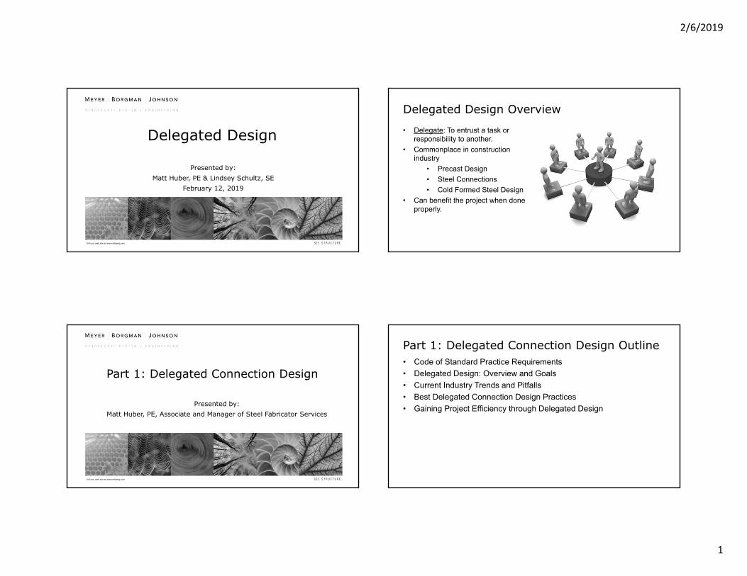
Delegated Design
Presented by:Matt Huber, PE & Lindsey Schultz, SE
February 12, 2019
Delegated Design Overview
• Delegate: To entrust a task or responsibility to another.
• Commonplace in construction industry
• Precast Design• Steel Connections• Cold Formed Steel Design
• Can benefit the project when done properly.
Visit our web site at www.mbjeng.com
Part 1: Delegated Connection Design
Presented by:Matt Huber, PE, Associate and Manager of Steel Fabricator Services
Part 1: Delegated Connection Design Outline• Code of Standard Practice Requirements• Delegated Design: Overview and Goals• Current Industry Trends and Pitfalls• Best Delegated Connection Design Practices• Gaining Project Efficiency through Delegated Design

2/6/2019
2
CODE OF STANDARD PRACTICE REQUIREMENTS
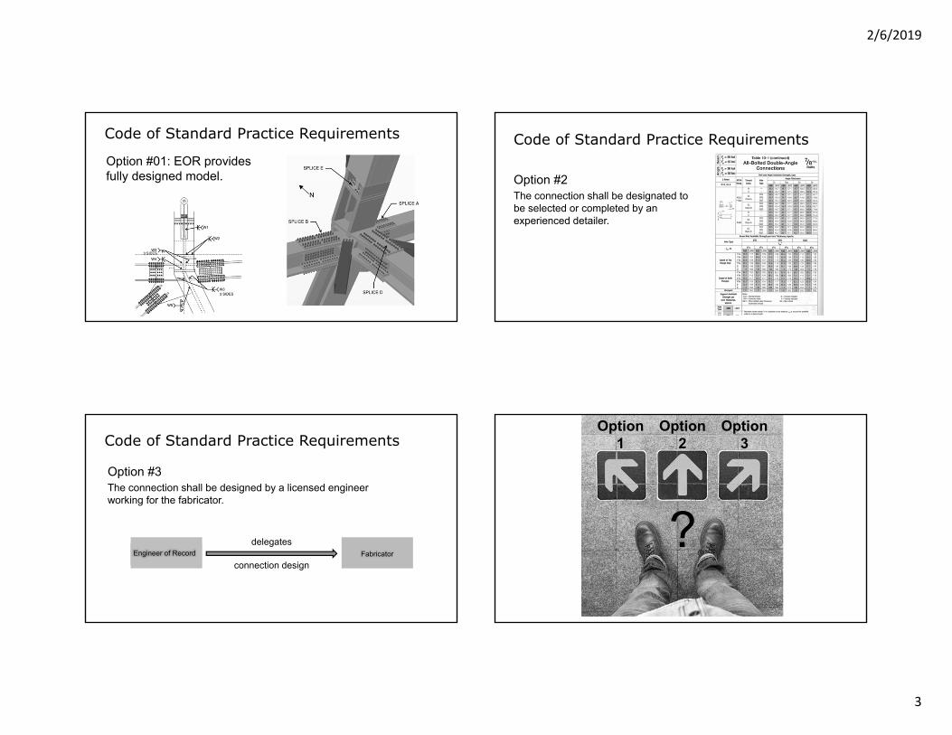
Code of Standard Practice Requirements
AISC 303-16 Section 3.1.1• EOR must provide guidance on
connection design• 3 Options
Code of Standard Practice Requirements
Option #1Connection design fully provided on contract documents (non-delegated)
Code of Standard Practice RequirementsOption #1: 2D DeliveryMost preferred non-delegated delivery.
2/6/2019
3
Code of Standard Practice Requirements
Option #01: EOR provides fully designed model.
Code of Standard Practice Requirements
Option #2The connection shall be designated to be selected or completed by an experienced detailer.
Code of Standard Practice Requirements
Option #3 The connection shall be designed by a licensed engineer working for the fabricator.
Engineer of Record Fabricatorconnection design
delegates
Option1
Option3
Option2
?
2/6/2019
4
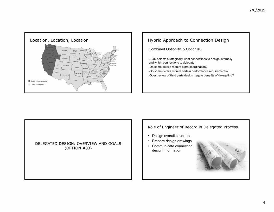
Location, Location, Location
MONTANA
WYOMING
IDAHO
WASHINGTON
OREGON
NEVADA
UTAH
CALIFORNIA
ARIZONA
NORTH DAKOTA
SOUTH DAKOTA
NEBRASKA
COLORADO
NEW MEXICO
TEXAS
OKLAHOMA
KANSAS
ARKANSAS
LOUISIANA
MISSOURI
IOWA
MINNESOTA
WISCONSIN
ILLINOISINDIANA
KENTUCKY
TENNESSEE
MISSALABAMA
GEORGIA
FLORIDA
SOUTHCAROLINA
NORTH CAROLINA
VIRGINIAWV
OHIO
MICHIGAN NEW YORK
PENN
MARYLAND
DELAWARE
NEWJERSEY
CONNRI
MASS
MAINE
VTNH
Option 1: Non-delegated
Option 3: Delegated
Hybrid Approach to Connection Design
Combined Option #1 & Option #3
-EOR selects strategically what connections to design internally and which connections to delegate.-Do some details require extra coordination?-Do some details require certain performance requirements?-Does review of third party design negate benefits of delegating?
DELEGATED DESIGN: OVERVIEW AND GOALS(OPTION #03)
Role of Engineer of Record in Delegated Process
• Design overall structure• Prepare design drawings• Communicate connection
design information

2/6/2019
5
Role of Fabricator in Delegated Process
• Procure and fabricate the structural steel
• Manage the connection engineer and erector
Role of Connection Engineer in Delegated Process
Design connections for the fabricator that meets design requirements set forth in the contract documents
Engineer of Record Self Interests
Minimize Risk
Reduce Efforts Maximize Profits
Avoid Re-work
Protect Relationship
Schedule
Engineer of Record Fabricator/Erector
Fabricator Self Interests
Shop Preferences
Reduce Fabrication
CostsMaximize
Profits
Schedule
Constructible Structure

2/6/2019
6
Connection Engineer Self Interests
Protect Relationship
Maximize Profits
Schedule
Economical Designs
Reduce Efforts
Connection Engineer
Intersecting Interests
The intersection of all parties’ interests is where projects tend to be most successful!
Engineerof Record
Fabricator/Erector
ConnectionEngineer
CURRENT INDUSTRY TRENDS AND PITFALLS
Specifying Shear Loads3 common ways of relaying shear load information • % of uniform design load (UDL)• Shear schedule• Shear loads noted on design documents

2/6/2019
7
Specifying Shear Loads% of uniform design load (UDL)• Typically 50%• More for composite framing• Defies logic• Cost • Quick and easy for EOR• Reduces EOR risk (?)
Specifying Shear Loads% of uniform design load (UDL) Example• W10x22 x 4’-0” Long• 50% UDL
Specifying Shear Loads% of uniform design load (UDL)• Per 14th Edition AISC Manual Table 3-6,
total load supported = 97.9 kips• Va = 97.9 kips/2 = 49 kips• Shear Capacity of member?• This equates to 24.4 klf
Specifying Shear Loads% of uniform design load (UDL)• An F150 weighs approximately
6,000 pounds • A reaction of 49 kips at each end
means this W10x22 would be supporting (16) F150s!

2/6/2019
8
Specifying Shear Loads% of uniform design load (UDL)
Specifying Shear Loads% of uniform design load (UDL)
Specifying Shear LoadsShear schedule• Typical shear provided for
each nominal depth• Little effort from EOR• Typical shears may be high to
cover all cases• Taxing on lightly loaded
members
Specifying Shear LoadsShears shown on plan

2/6/2019
9
Specifying Moment Loads
• Full flexural capacity• Design moment loads provided
at each location• Moment load schedule
BEST DELEGATED CONNECTION DESIGN PRACTICES
Steel Fabricator
ArchitectConnection EngineerGeneral Contractor
Owner It’s ALL About Communication!

2/6/2019
10
What Does the EOR Need to Communicate?
Reference AISC 303-16 Section 3.1• Materials• Geometry• Loading information• Top of steel elevations• Bidding information for member
reinforcement
What Else Should the EOR Communicate?• Permitted connection concepts• Connection type restrictions• Special load path requirements• Other special requirements?
Don’t wait for the approval process to provide these clarifications!
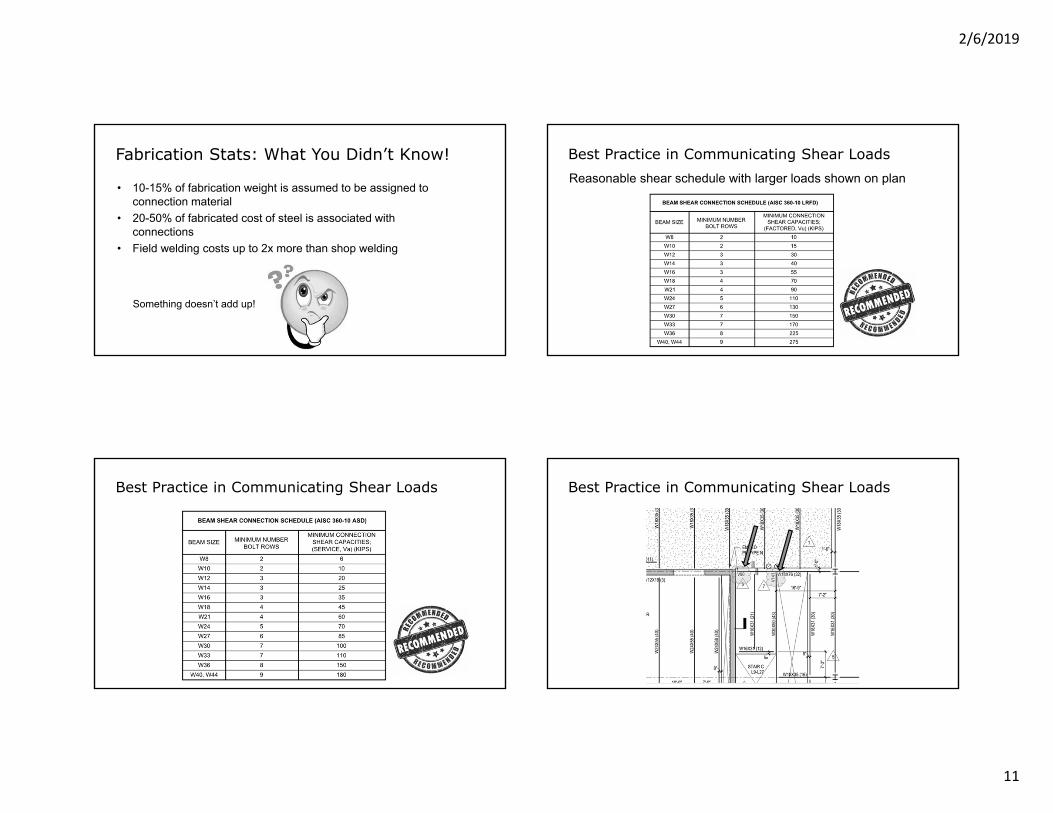
Fabrication Stats: What You Didn’t Know!
Fabrication cost impacts of were discussed with a number of fabricators.
Connection Costs Large Impact on Bottom Line
2/6/2019
11
• 10-15% of fabrication weight is assumed to be assigned to connection material
• 20-50% of fabricated cost of steel is associated with connections
• Field welding costs up to 2x more than shop welding
Fabrication Stats: What You Didn’t Know!
Something doesn’t add up!
Best Practice in Communicating Shear LoadsReasonable shear schedule with larger loads shown on plan
Best Practice in Communicating Shear Loads Best Practice in Communicating Shear Loads

2/6/2019
12
Best Practice in Communicating Moment Loads
Provide design moment at all locations
Allow Moment Connection Options
Alternative to Full Flexural Capacity• Full flexural capacity requires….
• Direct welded connection• Reinforced or unreinforced flange plated connection
Flange Reinforcement due to FlexureAISC Specification Section F13
0%
10%
20%
30%
40%
50%
60%
70%
80%
90%
70% 75% 80% 85% 90% 95% 100%
% of T
otal W
F
% of Flexural Capacity
% of Common WF Members Require AISC Section F13 Flange Reinforcement
3/4" Dia. Bolts
7/8" Dia. Bolts
1" Dia. Bolts
1‐1/8" Dia. Bolts

2/6/2019
13
Reduce Reinforcing with Proper Member Selection• Member Reinforcement = • Size members to avoid stiffeners• Avoid minimum reinforcing
requirements
Proper way to delegate is to note reinforcement plate AS or WHEN required
Reduce Reinforcing with Proper Member Selection
Is the Fabricator or the EOR responsible for understanding member reinforcement requirements?
Reduce Reinforcing with Proper Member Selection• COSP AISC 303-16 Section 3.1.2 puts some responsibility
on EOR• Option A: Member reinforcement at connection
provided by EOR at bidding time.• Option B: EOR provides concept and bidding quantity
at bidding time.
Creates equal playing field for all Fabricators during bidding phase!
Proper Member Selection
• Average WF column = $900-$1200 per ton• Average pair of stiffeners = $156• Single doubler = $438
Comparison• Unreinforced W14x90 x40’-0”
long will cost roughly $1600• W14x90 x 40’-0” reinforced
could cost up to $3000
Prices Based on Fabricator Input…

2/6/2019
14
Proper Member SelectionPrices Based on Fabricator Input…
Upsize to W14x132 costs roughly $2375
Moment Connection Cost Impact
Full Moment Capacity- Direct Welded
• Cheapest to fab• Most expensive to erect• Highest schedule impact
• Most expensive to fab• Average erection costs• Negligible schedule impact
Moment Connection Cost Impact
Full Moment Capacity- Flange Plate with Reinforcement
• Average fab costs• Cheapest to erect• Negligible schedule impact
Moment Connection Cost Impact
Reduced Design Moment- Flange Plate

2/6/2019
15
Cost Impact Summary• Fabrication costs varied widely• Erection costs varied widely• Least desirable connection =
direct welded• Most preferable = flange plate
(no reinforcement)
Give Fabricator Options!!
GAINING PROJECT EFFICIENCY THROUGH DELEGATED DESIGN
Tip#1: Relax on the Envelope Loads
• Provide loading clarity• Keep an eye on your
interaction checks• Tabulated connection
information
Tip#2: Vertical Brace Loads• Provide Axial Loads• Provide Different Tension vs.
Compression Loads• No load combinations

2/6/2019
16
Tip#3: Vertical Brace Force Directionality• Is bracing tension and
compression only?• Be clear with specific
vertical brace loading requirements.
Tip#3: Vertical Brace Force Directionality
Critical details should require more attention to detail.
Tip#4: Vertical Brace Force Minimums• Minimum bracing loads• % of capacity
Simply provide design loads
Tip#5: Brace Connection Load Distribution
Do not provide connection interface forces

2/6/2019
17
Tip#6: Clarify Moment Directionality• Loads due to gravity only?• Reversible loads?
Tip#7: Moment DirectionalityMoment Loads at Column: How much is transferred into the column?
Tip#8: Panel Zone InformationAISC 360-10 Section J10.6
Tip#9: Specifying Axial LoadsProvide clear load path
200 kip axial load?

2/6/2019
18
Tip#9: Specifying Axial Loads
P=450k
Provide clear load path
Tip#10: Provide Clear and Precise Architectural and Dimensional Restraints
• If critical, provide direction on connection size limitations.• Examples:
• Column wraps• MEP Coordination• Ceiling/wall clearances
Tip#10: Provide Clear and Precise Architectural and Dimensional Restraints
• No Typical Chevron Detail Provided on Design Documents
Tip#10: Provide Clear and Precise Architectural and Dimensional Restraints
• Getting Better!

2/6/2019
19
Tip#10: Provide Clear and Precise Architectural and Dimensional Restraints
• Clear direction finally provided!
Tip#11: Focus on Expansion and Slip Joints• Careful consideration of
performance of expansion and slide bearing joints is needed.
• Accurately portray expansion requirements.
• What are movement requirements?
Tip#11: Focus on Expansion and Slip Joints
• Example
• Perfect Placement Results in 9/16” of movement in the joint.
Tip#11: Focus on Expansion and Slip Joints
• Consider erection tolerances
• Understanding of Installation temperature
• Understand distance between expansion joints

2/6/2019
20
Tip#11: Focus on Expansion and Slip Joints
• Lack of ‘attention to detail’ led to connection failure.
• Connections were replaced on site.
Tip#12: Avoid Specifying SC(B) Connections
• Not all shops are set up to blast.
• Provide fabricator with flexibility to commercial blast steel.
• SSPC-SP6 versus SSPC-SP2
Tip#13: Avoid Requiring Field Welds
• Provide Fabricator and Erector flexibility.
• Field welding could be more than 2x costly than shop welds
• Location, Location, Location
Tip#14: Keep Welds to a Single Pass
• Welds up to 5/16” thick can be made using a single pass.
• Design welds for loads, avoiding large minimums.
• AISC 14th Edition Manual Table 8-12.
2/6/2019
21
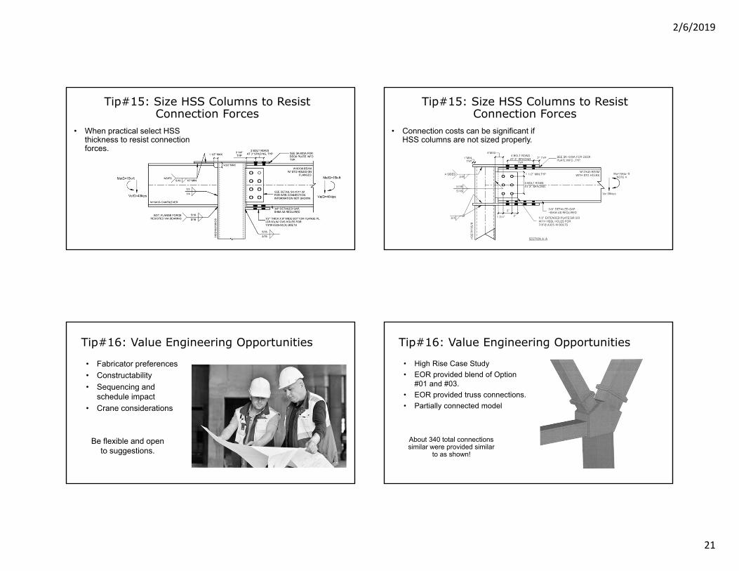
Tip#15: Size HSS Columns to Resist Connection Forces
• When practical select HSS thickness to resist connection forces.
Tip#15: Size HSS Columns to Resist Connection Forces
• Connection costs can be significant if HSS columns are not sized properly.
Tip#16: Value Engineering Opportunities
• Fabricator preferences• Constructability• Sequencing and
schedule impact• Crane considerations
Be flexible and open to suggestions.
Tip#16: Value Engineering Opportunities
• High Rise Case Study• EOR provided blend of Option
#01 and #03.• EOR provided truss connections.• Partially connected model
About 340 total connections similar were provided similar
to as shown!

2/6/2019
22
Tip#16: Value Engineering Opportunities
• 3rd Party Consultant hired by EOR.
• Provided alternative connection at bid time.
• Two Options Benefits the owner.
Options are great, but is it good enough?
Tip#16: Value Engineering Opportunities • MBJ was hired by fabricator
to provide 3rd Alternative.• Solution was a lighter, more
Fabricator friendly connection.
• Customized for Fabricator preferences.
Alternative design was expected to save the
project 4-5 million dollars!
Summary of Delegating Connections
If you take 3 things from this presentation today, remember these:
1. Clear communication of delegated design requirements
2. Provide reasonable design requirements and loads
3. Provide fabricator with connection configuration options
Visit our web site at www.mbjeng.com
Delegated Connection Design Questions?

2/6/2019
23
Visit our web site at www.mbjeng.com
Part 2: Delegated Design for
Cold Formed Metal Framing
Presented by:Lindsey Schultz, SE (AZ),
Structural Engineer and Office Leader of Arizona Office
Part 2: Delegated Design for Cold‐Formed Steel Framing Outline
• Code of Standard Practice Requirements and Other Resources• Benefits and Challenges for CFS as a Deferred Submittal• Recommendations for Construction Documents and Specifications• CFS Framing Trends • Common Coordination Challenges• Project Example / Case Study
Poll The Audience Poll The Audience
• AISI Code of Standard Practice for the Cold‐Formed Steel Structural Framing
• Definitions• Building Designer – Owner of the building or the person
that contracts with the owner for the design of the framing structural system or who is responsible for the preparation of the construction documents. When mandated by the legal requirements, the building designer shall be a registered design professional.
• Specialty Designer – The registered design professional, individual or organization having responsibility for the design of the specialty items. The requirement for a Specialty Designer is typically called out in the specifications or structural general notes. The Specialty Designer is typically not the building designer.

2/6/2019
24
Poll The Audience
• AISI Code of Standard Practice for the Cold‐Formed Steel Structural Framing
• Types of CFS Construction• Façade Framing
• Metal Buildings• Concrete/Steel Frames
• Metal Deck• Trusses• Other Uses
• Solar• Manufacturing
Code of Standard Practice Requirements
• AISI Code of Standard Practice for the Cold‐Formed Steel Structural Framing
• Section A4 Responsibility for Design• Section C1 Responsibilities for Construction
Documents• Section D Installation Drawings
Code of Standard Practice Requirements• AISI Code of Standard Practice for the Cold‐Formed Steel Structural Framing
• Responsibility for Design• A4.1 Building Designer and Specialty
Designer• A4.2 Construction Documents• A4.3 Owner• A4.4 Contractor and Sub‐Contractor
Code of Standard Practice Requirements
• AISI Code of Standard Practice for the Cold‐Formed Steel Structural Framing
• Section C1 Construction Document Responsibilities• Documents shall show type of support supplied,
method of attachment, correct dimensions, and required min or max sizes and spacings.
• If Deferred submittal, specialty designer shall provide above noted information to EOR for review and approval.
• Architectural plans shall indicate the design intent of the CFS structural framing.
• Structural plans shall show the structural member locations, sizes, reinforcing and connections in sufficient scale and detail to enable to the construction of the building in a reasonable sequence.

2/6/2019
25
Code of Standard Practice Requirements
• AISI Code of Standard Practice for the Cold‐Formed Steel Structural Framing
• Installation Drawings• Section D1 Owner/Contractor Responsibility• Section D2 Component Manufacturer
Responsibility• Section D3 Review Process• Section D4 General Responsibility
Cold‐Formed Steel Resources
• AISI Codes – North American Standards for Cold‐formed Steel Framing – IBC 2012
• AISI S200 – General ProvisionsProvides basic information about installation tolerances, member design, connections and other basics for using and installing steel framing for construction
• AISI S100 – Specification for DesignThis contains the equations for design of members. It applies not only to steel members, but to all thin and cold‐formed steels used in construction
Cold‐Formed Steel Resources
• AISI Codes – North American Standards for Cold‐formed Steel Framing – IBC 2012
• AISI S212 – Header DesignProvides guidance for the design of three types of headers: boxed C‐shapes, back‐to‐back C‐shapes, and double “L” headers.
• AISI S211 – Wall Stud DesignProvides additional guidance for design of wall systems, in both loadbearing and nonloadbearing applications
Cold‐Formed Steel Resources
• AISI Codes – North American Standards for Cold‐formed Steel Framing – IBC 2012
• AISI S214 – Truss DesignGives design information for truss design responsibilities, loading, design criteria, quality criteria, installation, bracing, and testing of trusses and truss systems.
• AISI S210 – Floor and Roof System DesignThis standard is intended for the design and installation of cold‐formed steel framing for floor and roof systems in buildings. The standard provides a methodology for continuously braced design. The standard also includes provisions for clip angle bearing stiffeners.

2/6/2019
26
Cold‐Formed Steel Resources• AISI Codes – North American Standards for Cold‐formed Steel Framing – IBC 2012
• AISI S213 – Lateral Design• This standard addresses the design of lateral force resisting systems to resist wind and seismic forces in a wide range of buildings constructed with cold‐formed steel framing. It contains design requirements for shear walls, diagonal strap bracing and diaphragms.
• AISI S230 – Prescriptive Method for One‐ and Two‐family Dwellings• This standard provides prescriptive requirements for cold‐formed steel‐framed detached one‐ and two‐family dwellings, townhouses, attached multi‐family dwellings, and other attached single‐family dwellings. It includes numerous tables and details to allow buildings complying with the limitations therein to be constructed. Alternatively such dwellings may be designed by a design professional.
Cold‐Formed Steel Resources
• AISI Codes – North American Standards for Cold‐formed Steel Framing – Additional Standards
• AISI S202 ‐ Code of Standard Practice• AISI S220 ‐ Nonstructural Members• AISI S400 ‐ Seismic Design• AISI S240 – Structural Framing
Cold‐Formed Steel Resources
• Cold‐Formed Steel Engineers Institute (CFSEI)• AISI Codes• Various Design Guides Available
• Steel Stud Manufacturers Association (SSMA)• Steel Stud Properties• Load‐Span Tables
Cold‐Formed Steel Resources
• Software

2/6/2019
27
Why do Cold‐Formed Metal Framing as a Deferred Submittal?
• PROS• More flexibility for installer• Efficient designs by specialty
designer• Knowledge of availability for
procurement• Coordination with
construction sequence
Why do Cold‐Formed Metal Framing as a Deferred Submittal?
• CHALLENGES• Construction Schedule• Load Path Verification
Why do Cold‐Formed Metal Framing as a Deferred Submittal?
Recommendations for Construction Documents and Specifications• General Structural Notes• Deferred Submittal• Applicable Building Codes• Aligned with Specifications

2/6/2019
28
Recommendations for Construction Documents and Specifications• Structural Drawings• Structural Member Locations and Sizes• CFS Connections in sufficient detail to
enable construction of the building in a reasonable sequence
• Aligned with Specifications
• Architectural Drawings• Design Intent• Member size constraints• Location within the structure• Dimensions• Aligned with Specifications
Recommendations for Construction Documents and Specifications
Recommendations for Construction Documents and Specifications
• Specifications 05 40 00• Design Criteria and Responsibilities• Member Size and Connection Criteria• Performance Requirements• Aligned with Drawings
Recommendations for Construction Documents and Specifications
• Specifications 05 40 00• General
• Performance Requirements• Design Responsibilities
• Products• Execution

2/6/2019
29
CFS Framing Trends
• The Labor Shortage
CFS Framing Trends
• Pre‐fabrication and Modularization
CFS Framing Trends
• Alternate Member Configurations
CFS Framing Trends• Connections – Manufactured Clips vs. Field Fabricated

2/6/2019
30
CFS Framing Trends• Performance Requirements• Deflection Criteria per IBC
• L/180 – Interior walls and partitions• L/360 – Exterior walls with plaster or stucco• L/240 – Exterior walls with brittle finishes• L/120 – Exterior walls with flexible finishes• L/180 – Exterior walls with gypsum board interior finish
• 2018 IBC• L/175 for walls supporting glass less than 13’‐6” and L/240 + ¼” for spans greater than 13’‐6”
• Brick Industry Association• L/600 – Brick walls
CFS Framing Trends• Performance Requirements• Energy Efficiency
• Continuous Ribbon Windows• Coordinate Kicker locations with
other disciplines• Coordinate Slab edge
• A bypass condition is preferred by framer
• Precast loads on steel studs and slab edge
Common Coordination Challenges• Fire‐Proofing Coordination• Spray on Fire‐proofing
Common Coordination Challenges

2/6/2019
31
• Construction Sequencing• Alternate Bypass Conditions
Common Coordination Challenges Common Coordination Challenges• Construction Sequencing• Splice Locations
• CFSEI TN W106 Design for Splicing of Cold‐Formed Steel Wall Studs
• Damaged Studs• Web Holes• Coped Flanges• Punch location
Common Coordination Challenges• University of Arizona Biosciences Partnership Building
Biosciences Partnership Building

2/6/2019
32
• Design Team• Architect – CO Architects and Ayers Saint Gross• Structural EOR – Martin & White• GC – DPR • Cold‐Formed Steel Sub‐contractor ‐ DPR• Specialty Designer ‐ MBJ
Biosciences Partnership Building• University of Arizona Biosciences Partnership Building• 10‐story research building is LEED Silver certified• Copper Panel façade
Biosciences Partnership Building
• Sunscreen• Panels with 2” air space,
rigid insulation and waterproofing membrane
Biosciences Partnership Building• Prefabricated Panels• Copper Panel façade
• 24 copper panels
Biosciences Partnership Building• Embed Coordination and Reactions at Structure

2/6/2019
33
Biosciences Partnership Building• Supplemental Steel
Visit our web site at www.mbjeng.com
COLD FORMED METAL FRAMING QUESTIONS?