Embed Size (px)
Citation preview
1 Bulletin 3D-5 Page
U·n..i:ted ..., " Date Oct. 1968
Delco Supersedes 3D-5 Dated Nov. 1967
AC SERVICE BULLETIN� AC ELECTRONIC TACHOMETER REPAIR�
PARTS 1, 2, and 3
Part 1 - Pages 1 through 22 pertain to General Operating Principals and Servicing of Tachometers using an engine or ignition simulator for testing and calibration.
Part 2 - Pages 23 through 27 pertain to the use of the *TC 100 for testing, calibration and service.
Part 3 - Pages 28 through 31 pertain to the use of an Oscilloscope for troubleshooting the circuit assembly and replacement of defective electrical components.
PART 1 General Explanation of Operation
The ignition pulse is carried by a single wire from the distributor side of the ignition coil to the insulated terminal on the back of the tachometer case. The additional insulated terminals, if present, are battery terminals used for lighting and/or transistor operation.
This pulse is smoothed out and modified by the various electrical components in the circuit package.
This modified ignition pulse current is then drawn through the meter movement where it causes meter coil and attached pointer deflection, interpreted as the number of pulses per unit time (revolutions per minute), as the pointer moves across the calibrated dial.
TOOLS AND EQUIPMENT NEEDED FOR DISASSEMBLY, REASSEMBLY, DIAGNOSIS, AND CALIBRATION
1. Small hand tools.
a. No. 10 nut driver
b. No.2 nut driver.
c. Medium blade common screwdriver.
d. Small tipped, fast-heating, soldering iron.
e. Long nose pliers.
f. Tweezers.
2. Test Equipment.
a. Milliammeter (0 to 1 milliampere) with an internal coil resistance of 100 ohms ± 10 (Ideal Precision Meter Company Model 350 P-C or equivalent).
Ideal Precision Meter Co.� 214 Franklin Street� Brooklyn, New York�
b. Test tachometer (Type used in performance of automotive service. Combination tach dwell is satisfactory.)
c. Variable resistor (10,000 to 100,000 ohms). If unable to obtain, purchase 0 to 100,000 resistor and place 10,000 resistor in series to prevent accidental meter burnout.
d. Eight, six, or four cylinder (to match tachometer being serviced) car with negative ground (unless otherwise specified) in which the ignition components are in good working order.
*Available from Landmesser Tools, 980 S. Cass Lake Road, Pontiac, Mich.
WD, X 131,132:16, FD (°1968 General Motors Corporation
UNITED MOTORS SERVICE PRINTED IN U.S.A. DIVISION OF GENERAL MOTORS CORPORATION
CENTRAL OFFICE-OETROIT

Bulletin 3D-5 Page 2 Date Oct. 1968
AC SERVICE BULLETIN
AC ELECTRONIC TACHOMETER REPAIR
GENERAL
1. Servicing of tachometers which are similar in design and servicing procedures are divided into groups, i.e. 1, 2, and 3. If both the meter movement and circuit package is defective, tachometer replacement is recommended. Tachometers not listed are serviced by replacement.
2. An ignition simulator consisting of a 12 volt battery, primary resistor, ignition coil, distributor cap, all spark plugs and a motor driven 8, 6, or 4 cyl. * distributor (to match tachometer being serviced) may be used for circuit testing and tachometer calibration. A kit containing a sewing machine motor with variable resistor is available from Clark Bros. Instrument Corp., 10300 Whittier Avenue, Detroit, Michigan for driving a distributor.
*All the spark plugs should be in the circuit. If more convenient, onlyone plug may be used, providedall of the distributor towers are wired together to fire the one plug being used.
Note:� An 8 cyl. engine or an ignition simulator equipped with an 8 cyl. distributor may be used for testing tachometers. Distributor RPM and tachometer reading are as follows:
Type of Tachometer Dist. RPM� Tach. Should Read
8 cyl,� 1000 2000 6 eyl.� 1000 2666 4 cyl.� 1000 4000
3. Prior to any disassembly,� meter or circuit package testing, the tachometer should be bench tested. If an engine response is being used for evaluation, vary r.p.m. from idle to 2000 r.p.m.-if simulator response is being used, vary indication from idle to 5000 r.p.m. (Do not exceed this value as distributor point bounce can occur, thus causing inaccurate reading.) Note tachometer performance. If no defect is apparent, it is then advisable to disassemble and visually inspect meter air gap for offending particles which could cause intermittent operation.
4. Reassembly. Reassemble all� tachometers in reverse order of disassembly. Use masking tape to temporarily secure bezel to case.
5. If the meter assembly zero position has shifted, exert a clockwise or counterclockwise pressure on either front or rear zero adjustment arm to obtain proper adjustment.
6. Static electricity on lucite lens may cause off zero pointer conditions. To eliminate, wipe both sides of lucite lens with a diluted household detergent.
7. When testing the meter movements, the movement of pointer from 0 to full scale should be smooth and even throughout the range of operation. Sluggishness or unequal degree of movement could be caused by tangled hairsprings or improper end play. The end play is factory adjusted and should not be tampered with. Any of the above indications would require the replacement of the meter movement.
If the meter appears sticky, the air gap and magnet surfaces should be examined for metal chips, lint or dirt. These foreign particles may sometimes be removed with long tweezers, or a small piece of folded masking tape. Quite often it is not possible to locate or extract the offending particle and it is then necessary to replace the meter movement.
8. When� testing the circuit assemblies, the test milliammeter action should be smooth throughout the range of operation. If no test milliammeter indication is received regardless of potentiometer position, or erratic readings are obtained on test milliammeter, the circuit assembly should be replaced.
Assemblies in which the electrical components are mounted on a ceramic board, do not have an adjustable potentiometer.
9. Commencing with 1968,� many tachometers incorporate a new feature in that the circuit board and other internal connections are made by a connecting lug and pin. It is important to note and record the color code before any disconnections are made.
To remove the lug from the pin, with long nose pliers apply a slight circular pulling force to the lug. Do not twist or bend as the pin can be broken at point of attachment.

3 Bulletin 3D-5 Page Date Oct. 1968
AC SERVICE BULLETIN
AC ELECTRONIC TACHOMETER REPAIR
Year Application RPM Tachometer Group
BUICK 1962-64 8 Cyl. 0-6000 6411300 1 1964 8 Cyl. Wildcat 0-6000 6411580 1 1965-68 8 Cyl. Wildcat 0-6000 6412326 1
BUICK SPECIAL 1962-63 8 Cyl. 0-6000 1549980 1 1962-64 6 Cyl. 0-6000 6411076 1 1964 8 Cyl. 0-6000 6411300 1 1965-68-69 8 Cyl. Gran Sport 0-6000 6412531 1 1965-68-69 6 Cyl. Gran Sport 0-6000 6412536 1
CHEVROLET 1963-64 8 Cyl. Super Sport (Exc. 409 Eng.) 0-6000 6411123 1 1963-64 8 Cyl. Super Sport 409 Eng. 0-7000 6411124 1 1961-62 8 Cyl. Super Sport 0-6000 6411241 1 1964 8 Cyl. Breakerless Ign. w/4 Spd. 0-7000 6411985 1 1964 8 Cyl. Breakerless Ign. Exc. 4 Spd, 0-6000 6411992 1 1965 8 Cyl. (Exc. H.P. 409 Eng. w/Close
Ratio 4 Speed Trans. 0-6000 6412235 1 1965 8 c-r. H.P. 409 Eng. w/Close
Ratio 4 Speed Trans. 0-7000 6412236 1 1965 8 Cyl. 409 Eng. Breakerless Ign. 0-6000 6412292 1 1965 8 Cvl. 409 Eng. Breakerless Ign. 0-7000 6412293 1 1966 8 Cyl. 0-6000 6412548 3 1966 8 Cyl. 0-7000 6412549 3 1966 8 Cvl, Breakerless Ign. 0-6000 6412571 3 1966 8 Cvl. Breakerless Ign. 0-7000 6412572 3 1966 8 Cyl. 0-7000 6412983 3 1966 8 Cvl. Breakerless Ign. 0-7000 6412984 3 1967 8 Cyl. 0-7000 6468333 3 1967 8 Cyl. 0-7000 6468334 3 1967 8 Cyl. 0-7000 6468336 3 1968 8 Cyl. Regular 0-7000 6468912 3 1968 8 Cyl. Regular 0-7000 6468913 3 1968 8 Cyl. Regular 0-7000 6468914 3
CHEVELLE 1964-65 8 Cyl. Super Sport 0-6000 6411826 1 1965 8 Cyl, Super Sport 0-6000 6412504 1 1965 8 Cyl. Breakerless Ign. 0-7000 6412735 1 1966 8 c-r. (Tach. & H'sng. 6412759) 0-6000 6412767 1 1966 8 c-r. (Tach. & H'sng. 6412764) 0-7000 6412774 1 1966 8 Cyl. Breakerless Ign. (Tach. &
H'sng. 6412765) 0-6000 6412778 1 1966 8 cvr. Breakerless Ign. (Tach. &
H'sng. 6412766) 0-7000 6412782 1 1966 8 Cyl. (Tach. & H'sng. 6412816) 0-7000 6412840 1 1966 8 Cyl. Breakerless Ign. (Tach. &
H'sng. 6412817) 0-7000 6412844 1
1967 8 Cyl. 0-7000 6468319 3
1967 8 Cyl. 0-7000 6468499 3
1967 8 c-r. 0-7000 6468500 3
1968 8 Cyl. 0-7000 6468821 3 0-7000 6468822 31968 8 Cyl. 0-7000 6468823 31968 8 Cyl.

Bulletin 3D-5 Page 4 Date Oct. 1968
AC SERVICE BULLETIN AC ELECTRONIC TACHOMETER REPAIR�
Year Application
CHEVELLE 1969 1969 1969
8 Cyl. 8 Cyl. 8 Cyl.
CAMARO 1967 8 Cyl. 1967 8 Cyl. 1967 8 Cyl. 1967 8 Cyl. 1967 8 Cyl. 1967 8 Cyl, 1968 8 Cyl. Clock Tachometer 1968 8 Cyl. Clock Tachometer 1968 8 Cyl. Clock Tachometer 1969 8 Cyl. 1969 8 Cyl, 1969 8 Cyl.
CHEVY II 1968 8 Cyl. 1968 8 Cyl. 1969 8 Cyl. 1969 6 Cyl. 1969 4 Cyl,
CORVAIR 1962 6 Cyl, Monza 1963-64 6 Cyl, Spyder 1965-66 6 Cyl. Turbo Charged Corsa
CHEVROLET TRUCK 1967-68-69 8 Cyl. 1967-68 8 Cyl, Breakerless Ign. 1967-68-69 6 Cyl. 1967-69 6 Cyl. School Bus 1967-69 8 Cyl. School Bus
GMC TRUCK 1965-66 P.M. Generator 1967-69 6 Cyl. 1967 P.M. Generator 1966 P.M. Generator 1968 6 Cyl, 1969 6 Cyl.
OLDSMOBILE 1961-62 8 Cyl.� 1963 8 Cyl,� 1964-66 8 Cyl.�
1965-66 8 Cyl.� 1967 8 Cyl. (Tach. & Clock Assy.)�
RPM Tachometer Group
0-7000 6491312 3 0-7000 6491313 3 0-7000 6491314 3
0-7000 6468695 3 0-7000 6468696 3 0-7000 6468697 3 0-7000 6468909 3 0-7000 6468910 3 0-7000 6468911 3 0-7000 6468713 3 0-7000 6468714 3 0-7000 6468715 3 0-7000 6469381 3 0-7000 6469382 3 0-7000 6469383 3
0-7000 6469100 3 0-7000 6469101 3 0-7000 6469362 1 0-7000 6469361 1 0-7000 6469360 1
0-6000 1549943 1 0-6000 6411412 1 0-6000 6412203 3
0-5000 6468228 3 0-5000 6468320 3 0-5000 6468321 3 0-5000 6468902 3 0-5000 6468903 3
0-4000 6411472 2 0-4000 6468270 3 0-3500 6468416 2 0-4000 6468521 2 0-4100 6468270 3 0-4100 6469489 3
0-6000 1549356 1 0-6000 6411363 1 0-6000 6411857 1 0-6000 6411782 1 0-7000 6457998 3
Bulletin Page Date
3D-5 5
Oct. 1968
AC SERVICE BULLETIN AC ELECTRONIC TACHOMETER REPAIR
Year Application
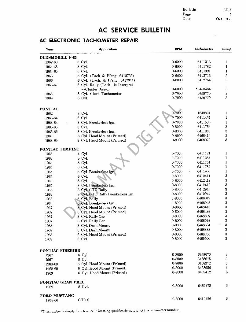
OLDSMOBILE F-85 1962-63 8 Cyl.� 1964-65 8 Cyl.� 1964-65 6 Cyl.� 1966 8 Cyl. (Tach & H'sng, 6412739)� 1966 6 Cyl. (Tach. & H'sng. 6412911)� 1966-67 8 Cyl. Rally (Tach. is Intergral�
w/Cluster Assy.)� 1968 8 Cyl. Clock Tachometer� 1969 8 Cyl.�
PONTIAC 1962 8 Cyl.� 1963-64 8 Cyl.� 1963-64 8 Cyl. Breakerless Ign.� 1965-66 8 Cyl.� 1965-66 8 Cyl. Breakerless Ign.� 1967 8 Cyl. Hood Mount (Primed)� 1968-69 8 Cyl. Hood Mount (Primed)�
PONTIAC TEMPEST 1963 4 Cyl.� 1963 8 Cyl.� 1964 8 Cyl.� 1964 6 Cyl.� 1964 8 Cyl. Breakerless Ign.� 1965 6 Cyl.� 1965 8 Cyl.� 1965 8 Cyl. Breakerless Ign.� 1966 8 Cyl. GTO Rally� 1966 8 Cyl. GTO Rally Breakerless Ign.� 1966 6 Cyl. Rally� 1966 6 Cyl. Breakerless Ign.� 1967 8 Cyl, Hood Mount (Primed)� 1967 6 Cyl. Hood Mount (Primed)� 1967 8 Cyl. Rally Car� 1967 6 Cyl. Rally Car� 1968 8 Cyl, Dash Mount� 1968 6 Cyl. Dash Mount� 1968 6 Cyl. Hood Mount (Primed)� 1969 8 Cyl.�
PONTIAC FIREBIRD 1967 6 Cyl.� 1967 8 Cyl.� 1968-69 8 Cyl. Hood Mount (Primed)� 1968-69 6 Cyl. Hood Mount (Primed)� 1969 6 Cyl, Hood Mount (Primed)�
PONTIAC GRAN PRIX 1969 8 Cyl.
FORD MUSTANG 1965-66 GT350
RPM Tachometer Group
0-6000 6411316 1 0-6000 6411782 1 0-6000 6411991 1 0-6000 6412716 3 0-6000 6412754 3
0-6000 *6458484 3 0-7000 6459770 3 0-7000 6459770 3
0-7000 1549831 1 0-7000 6411451 1 0-7000 6411585 1 0-8000 6411753 3 0-8000 6411835 3 0-8000 6468410 3 0-8000 6468972 3
0-7000 6411121 1 0-7000 6411284 1 0-7000 6411751 1 0-7000 6411752 1 0-7000 6411950 1 0-8000 6412411 3 0-8000 6412412 3 0-8000 6412413 3 0-8000 6412943 3 0-8000 6412944 3 0-8000 6468019 3 0-8000 6468023 3 0-8000 6468410 3 0-8000 6468436 3 0-8000 6468597 3 0-8000 6468598 3 0-8000 6468834 3 0-8000 6468833 3 0-8000 6468956 3 0-8000 6469500 3
0-8000 6468670 3 0-8000 6468675 3 0-8000 6468972 3 0-8000 6468956 3 0-8000 6469412 3
0-8000 6469478 3
0-8000 6412426 3
"This number is simply for reference in locating specifications, it is not the tachometer number.
Bulletin 3D-5 Page 6 Date Oct. 1968
AC SERVICE BULLETIN AC ELECTRONIC TACHOMETER REPAIR
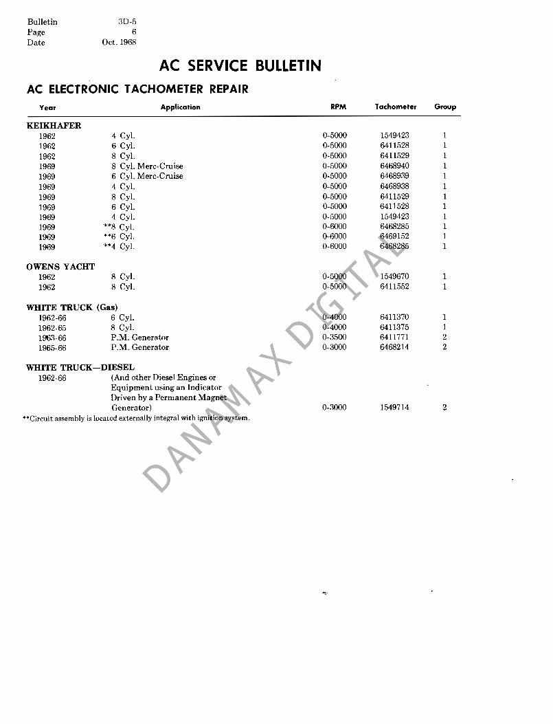
Year Application RPM Tachometer Group
KEIKHAFER 1962 4 Cyl. 0-5000 1549423 1 1962 6 Cyl, 0-5000 6411528 1 1962 8 Cyl. 0-5000 6411529 1 1969 8 Cyl. Mere-Cruise 0-5000 6468940 1 1969 6 Cyl. Mere-Cruise 0-5000 6468939 1 1969 4 Cyl. 0-5000 6468938 1 1969 8 Cyl. 0-5000 6411529 1 1969 6 c-r. 0-5000 6411528 1 1969 4 Cyl. 0-5000 1549423 1 1969 **8 Cyl. 0-6000 6468285 1 1969 **6 Cyl. 0-6000 6469152 1 1969 **4 Cyl, 0-6000 6468285 1
OWENS YACHT 1962 8 Cyl. 0-5000 1549670 1 1962 8 Cyl. 0-5000 6411552 1
WHITE TRUCK (Gas) 1962-66 6 Cyl. 0-4000 6411370 1 1962-65 8 Cyl. 0-4000 6411375 1 1963-66 P.M. Generator 0-3500 6411771 2 1965-66 P.M. Generator 0-3000 6468214 2
WHITE TRUCK-DIESEL 1962-66 (And other Diesel Engines or
Equipment using an Indicator Driven by a Permanent Magnet Generator) 0-3000 1549714 2
**Cireuit assembly is located externally integral with ignition system.
7 Bulletin 3D-5 Page Date Oct. 1968
AC SERVICE BULLETIN AC ELECTRONIC TACHOMETER REPAIR
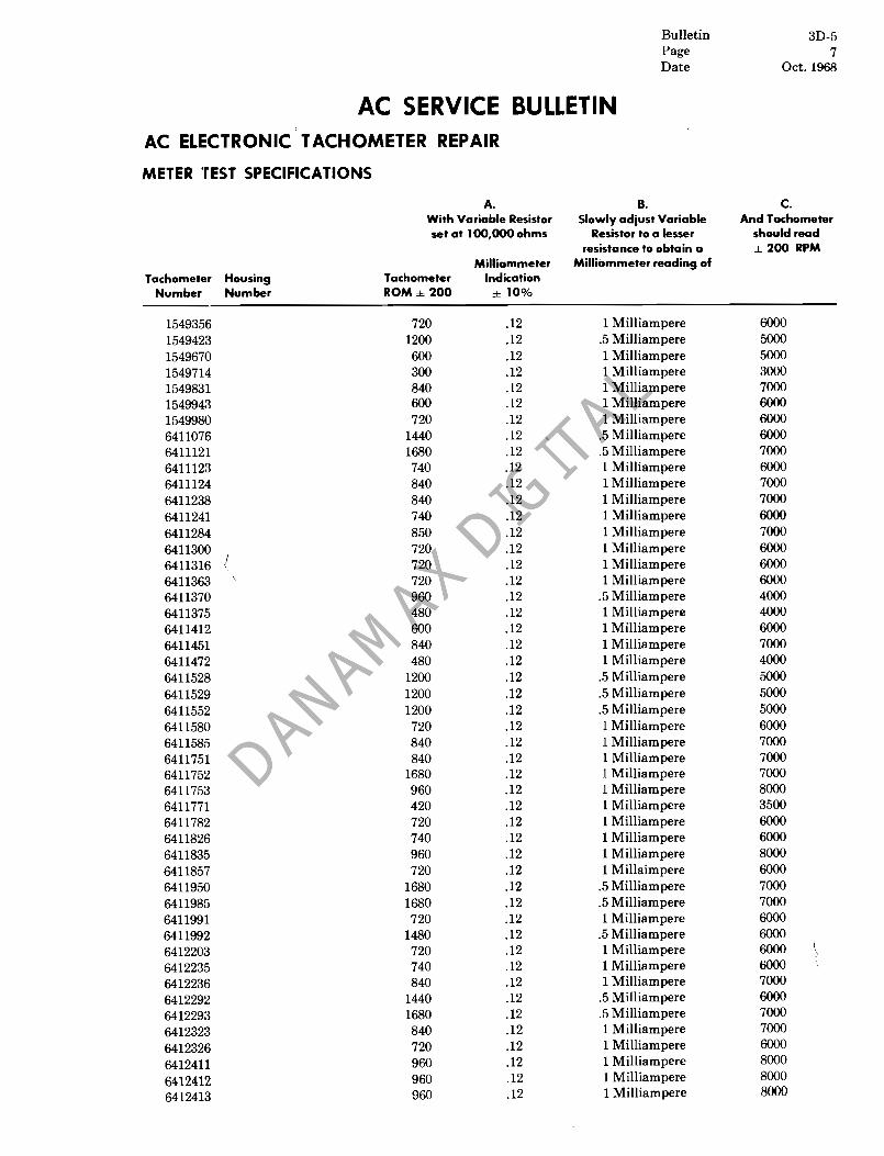
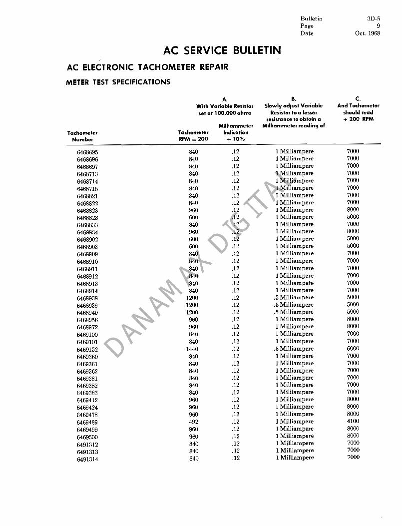
METER TEST SPECIFICATIONS
A. With Variable Resistor set at 100,000 ohms
Milliammeter Tachometer Housing Tachometer Indication
Number Number ROM ± 200 ± 10%
1549356 720 .12� 1549423 1200 .12� 1549670 600 .12� 1549714 300 .12� 1549831 840 .12� 1549943 600 .12� 1549980 720 .12� 6411076 1440 .12� 6411121 1680 .12� 6411123 740 .12� 6411124 840 .12� 6411238 840 .12� 6411241 740 .12� 6411284 850 .12� 6411300 720 .12� 6411316 .I 720 .12� 6411363 720 .12� 6411370 960 .12� 6411375 480 .12� 6411412 600 .12� 6411451 840 .12� 6411472 480 .12� 6411528 1200 .12� 6411529 1200 .12� 6411552 1200 .12� 6411580 720 .12� 6411585 840 .12� 6411751 840 .12� 6411752 1680 .12� 6411753 960 .12� 6411771 420 .12� 6411782 720 .12� 6411826 740 .12� 6411835 960 .12� 6411857 720 .12� 6411950 1680 .12� 6411985 1680 .12� 6411991 720 .12� 6411992 1480 .12� 6412203 720 .12� 6412235 740 .12� 6412236 840 .12� 6412292 1440 .12� 6412293 1680 .12� 6412323 840 .12�
6412326 720 .12�
6412411 960 .12�
6412412� 960 .12�
6412413 960 .12�
B. C. Slowly adjust Variable And Tachometer
Resistor to a lesser should read resistance to obtain a ± 200 RPM
Milliammeter reading of
1 Milliampere 6000� .5 Milliampere 5000� 1 Milliampere 5000� 1 Milliampere 3000� 1 Milliampere 7000� 1 Milliampere 6000� 1 Milliampere 6000�
.5 Milliampere 6000�
.5 Milliampere 7000� 1 Milliampere 6000� 1 Milliampere 7000� 1 Milliampere 7000� 1 Milliampere 6000� 1 Milliampere 7000� 1 Milliampere 6000� 1 Milliampere 6000� 1 Milliampere 6000�
.5 Milliampere 4000� 1 Milliampere 4000� 1 Milliampere 6000� 1 Milliampere 7000� 1 Milliampere 4000�
.5 Milliampere 5000�
.5 Milliampere 5000�
.5 Milliampere 5000� 1 Milliampere 6000� 1 Milliampere 7000� 1 Milliampere 7000� 1 Milliampere 7000� 1 Milliampere 8000� 1 Milliampere 3500� 1 Milliampere 6000� 1 Milliampere 6000� 1 Milliampere 8000� 1 Millaimpere 6000�
.5 Milliampere 7000�
.5 Milliampere 7000� 1 Milliampere 6000�
.5 Milliampere 6000� 1 Milliampere 6000� 1 Milliampere 6000� 1 Milliampere 7000�
.5 Milliampere 6000�
.5 Milliampere 7000� 1 Milliampere 7000� 1 Milliampere 6000� 1 Milliampere 8000� 1 Milliampere 8000� 1 Milliampere 8000�

Bulletin 3D-5� Page 8� Date Oct. 1968�
AC SERVICE BULLETIN AC ELECTRONIC TACHOMETER REPAIR
METER TEST SPECIFICATIONS
A.� With Variable Resistor� set at 100,000 ohms�
Milliammeter Tachometer Housing Tachometer Indication
Number Number RPM ± 200 ± 10%
6412426 960 .12� 6412504 740 .12� 6412531 720 .12� 6412536 720 .12� 6412548 720 .12� 6412549 840 .12� 6412571 720 .12� 6412572 840 .12� 6412716(6412739) 720 .12� 6412735 840 .12� 6412754 (6412911) 720 .12� 6412767 (6412759) 740 .12� 6412774(6412764) 840 .12� 6412778(6412765) 740 .12� 6412782 (6412766) 840 .12� 6412840(6412816) 840 .12� 6412844(6412817) 840 .12� 6412911 (6412754) 720 .12� 6412943 960 .12� 6412944 960 .12� 6412983 840 .12� 6412984 840 .12� 6457998 840 .12� 6458484 (Circuit & 720 .12�
Inst. Assy.)� 6459770 840 .12� 6468019 840 .12� 6468023 840 .12� 6468214 360 .12� 6468228 600 .12� 6468270 492 .12� 6468285 1440 .12� 6468319 840 .12� 6468320 600 .12� 6468321 600 .12� 6468333 840 .12� 6468334 840 .12� 6468336 840 .12� 6468410 960 .12� 6468416 400 .12� 6468436 960 .12�
6468499 840 .12�
6468500� 840 .12�
6468521 480 .12�
6468597� 960 .12�
6468598 960 .12�
6468662� 400 .12� 840 .12�6468670�
6468675� 840 .12�
B. C. Slowly adjust Variable And Tachometer
Resistor to a lesser should read resistance to obtain a ± 200 RPM
Milliammete~reading of
1 Milliampere 8000� 1 Milliampere 6000� 1 Milliampere 6000� 1 Milliampere 6000� 1 Milliampere 7000� 1 Milliampere 7000� 1 Milliampere 6000� 1 Milliampere 7000� 1 Milliampere 6000� 1 Milliampere 7000� 1 Milliampere 6000� 1 Milliampere 6000� 1 Milliampere 7000� 1 Milliampere 6000� 1 Milliampere 7000� 1 Milliampere 7000� 1 Milliampere 7000� 1 Milliampere 6000� 1 Milliampere 8000.� 1 Milliampere 8000� 1 Milliampere 7000� 1 Milliampere 7000� 1 Milliampere 7000� 1 Milliampere 6000�
1 Milliampere 7000� 1 Milliampere 8000� 1 Milliampere 8000� 1 Milliampere 3000� 1 Milliampere 5000� 1 Milliampere 4100�
.5 Milliampere 6000� 1 Milliampere 7000� 1 Milliampere 5000� 1 Milliampere 5000� 1 Milliampere 7000� 1 Milliampere 7000� 1 Milliampere 7000� 1 Milliampere 8000� 1 Milliampere 3500� 1 Milliampere 8000� 1 Milliampere 7000� 1 Milliampere 7000� 1 Milliampere 4000� 1 Milliampere 8000� 1 Milliampere 8000� 1 Milliampere 3500� 1 Milliampere 7000� 1 Milliampere 7000�
9 Bulletin 3D-5 Page Date Oct. 1968
AC SERVICE BULLETIN
AC ELECTRONIC TACHOMETER REPAIR
METER TEST SPECIFICATIONS
A.� With Variable Resistor� set at 100,000 ohms�
Milliammeter Tachometer Tachometer Indication
Number RPM ± 200 ± 10%
6468695 840 .12� 6468696 840 .12� 6468697 840 .12� 6468713 840 .12� 6468714 840 .12� 6468715 840 .12� 6468821 840 .12� 6468822 840 .12� 6468823 960 .12� 6468828 600 .12� 6468833 840 .12� 6468834 960 .12� 6468902 600 .12� 6468903 600 .12� 6468909 840 .12� 6468910 840 .12� 6468911 840 .12� 6468912 840 .12� 6468913 840 .12� 6468914 840 .12� 6468938 1200 .12� 6468939 1200 .12� 6468940 1200 .12� 6468956 960 .12� 6468972 960 .12� 6469100 840 .12� 6469101 840 .12� 6469152 1440 .12� 6469360 840 .12� 6469361 840 .12� 6469362 840 .12� 6469381 840 .12� 6469382 840 .12� 6469383 840 .12� 6469412 960 .12� 6469424 960 .12� 6469478 960 .12� 6469489 492 .12� 6469499 960 .12� 6469500 960 .12�
6491312 840 .12�
6491313 840 .12�
6491314 840� .12�
B. c. Slowly adjust Variable And Tachometer
Resistor to a lesser should read resistance to obtain a ± 200 RPM
Milliammeter reading of
1 Milliampere 7000� 1 Milliampere 7000� 1 Milliampere 7000� 1 Milliampere 7000� 1 Milliampere 7000� 1 Milliampere 7000� 1 Milliampere 7000� 1 Milliampere 7000� 1 Milliampere 8000� 1 Milliampere 5000� 1 Milliampere 7000� 1 Milliampere 8000� 1 Milliampere 5000� 1 Milliampere 5000� 1 Milliampere 7000� 1 Milliampere 7000� 1 Milliampere 7000� 1 Milliampere 7000� 1 Milliampere 7000� 1 Milliampere 7000�
.5 Milliampere 5000�
.5 Milliampere 5000�
.5 Milliampere 5000� 1 Milliampere 8000� 1 Milliampere 8000� 1 Milliampere 7000� 1 Milliampere 7000�
.5 Milliampere 6000� 1 Milliampere 7000� 1 Milliampere 7000� 1 Milliampere 7000� 1 Milliampere 7000� 1 Milliampere 7000� 1 Milliampere 7000� 1 Milliampere 8000� 1 Milliampere 8000� 1 Milliampere 8000� 1 Milliampere 4100� 1 Milliampere 8000� 1 Milliampere 8000� 1 Milliampere 7000� 1 Milliampere 7000� 1 Milliampere 7000�

Bulletin 3D-5 Page 10 Date Oct. 1968
AC SERVICE BULLETIN AC ELECTRONIC TACHOMETER REPAIR
CIRCUIT ASSEMBLY TEST SPECIFICATIONS USING ENGINE OR IGNITION SIMULATOR
A. B. A. B. Adjust Make Final Adjust Make Final
Potentio- Adjustment Potentio- Adjustment meter to to provide meter to to provide provide a a Milliam- provide a a Milliam-
Tachometer Milliammeter meter Tachometer Housing Milliammeter meter Number indication of 0- indication of Number Number indication of 0- indication of
1549356 .33 .33 6412236� .28 .28 (a) 1549423� .20 .20 (b)6412292 .17 .17
1549670 .40 .40 (b)6412293 .17 .17 1549714 .67 .67 6412323 .28 .28 1549831 .28 .28 6412326 .33 .33 1549943 .33 .33 (a)6412411 .25 .25 1549980 .33 .33 (a)6412412 .25 .25
(a) (c)6411076� .17 .17 (a) (b )6412413 .25 .25 6411121 .14 .14 (a)6412426 .25 .25 6411123 .33 .33 6412504 .33 .33 6411124 .28 .28 6412531 .33 .33 6411238 .28 .28 6412536 .33 .33 6411241 .33 .33 (a)6412548 .33 .33 6411284 .28 .28 (a)6412549 .28 .28 6411300 .33 .33 (a) (b)6412571 .33 .33 6411316 .33 .33 (a) (b)6412572 .28 .28 6411363 .33 .33 (a)6412716 (6412739) .33 .33
(a)6411370 .25 .25 6412735 .28 .28 See Note 1 (a)6412754 (6412911) .33 .33
6411375 .50 .50 6412767(6412759) .33 .33 See Note 1 6412774 (6412764) .28 .28
6411412 .33 .33 (b)6412778 (6412765) .33 .33 6411451 .28 .28 (b)6412782 (6412766) .28 .28 6411472 .50 .50 6412840 (6412816 .28 .28
(a)6411528 .20 .20 (b)6412844 (6412817) .28 .28 (a)6411529 .20 .20 6412911 (6412754) .33 .33 (a)6411552 .20 .20 (a)6412943 .25 .25
6411580 .33 .33 (a) (b)6412944 .25 .25 (b)6411585 .28 .28 (a)6412983 .28 .28
6411751 .28 .28 (a) (b)6412984 .28 .28 6411752 .28 .28 6457998 .28 .28
(a)6411753 .25 .25 6458484 (Circuit & 6411771 .43 .43 Inst. Assy.) .33 .33 6411782 .33 .33 6459770 .28 .28
(a)6411826 .33 .33 (a)6468019 .25 .25 (b)6411835 .25 .25 (a) (b)6468023 .25 .25
6411857 .33 .33 6468214 .67 .67 (b)6411950 .15 .15 6468228 .40 .40 (b)6411985 .15 .15 6468270 .49 .49
6411991 .33 .33 6468285 .17 (b)6411992 .17 .17 6468319 .28 (a)6412203 .33 .33 *6468320 .40 .40
6412235 .33 .33
*Breakerless Ignition.�
Note I: This Tachometer is used on a positive ground system.� (a) When testing the circuit assembly of this Tachometer, a 100 ohm resistor must be used in series with Milliammeter. (b) Indicates use in a breakerless ignition system. (c)� May be stamped 6411993.

Bulletin 3D-5 Page 11 Date Oct. 1968
AC SERVICE BULLETIN� AC ELECTRONIC TACHOMETER REPAIR
CIRCUIT ASSEMBLY TEST SPECIFICATIONS USING ENGINE OR IGNITION SIMULATOR
A. B. A. B. Adjust Make Final Adjust Make Final
Potentio- Adjustment Potentio- Adjustment meter to to provide meter to to provide provide a a Milliam- provide a a Milliam-
Tachometer Milliammeter meter Tachometer Housing Milliammeter meter Number indication of 0- indication of Number Number indication of 0- indication of
6468321 AO AO 6468909 .28 .28 6468333 .28 .28 6468910 .28 .28 6468334 .28 .28 6468911 .28 .28 6468336 .28 .28 6468912 .39 6468410 .25 .25 6468913 .39 6468416 .57 .57 6468914 .39 6468436 .25 .25 6468938 .20 .20 6468499 .28 6468939 .20 .20 6468500 .28 6468940 .20 .20 6468521 .50 .50 6468956 .25 6468597 .25 .25 6468972 .25 6468598 .25 .25 6469100 .28 6468662 .57 .57 6469101 .28 6468670 .28 .28 6469152 .17 6468675 .28 .28 6469360 .28 6468695 .28 .28 6469361 .28 6468696 .28 .28 6469362 .28 6468697 .28 .28 6469381 .28 6468713 .28 6469382 .28 6468714 .28 6469383 .28 6468715 .28 6469412 .25 .25 6468821 .28 6469424 .25 .25 6468822 .28 6469478 .25 6468823 .25 6469489 .50 6468828 AO AO 6469499 .25 6468833 .28 6469500 .25 6468834 .25 6491312 .29 6468902 AO 6491313 .29 6468903 AO 6491314 .29
Note:� Blank spaces in Column "B" indicate that Circuit Assembly has a Fixed Resistor instead of a Potentiometer, therefore is not adjustable. However, the circuit should provide the Milliammeter Specification shown in Column" A".

Bulletin 3D-5 Page 12 Date Oct. 1968
AC SERVICE BULLETIN AC ELECTRONIC TACHOMETER REPAIR
GROUP TACHOMETERS
The ignition lead-in connected to the insulated "coil" terminal at rear of case so identified. Those assemblies transistor operated have an additional insulated 12V terminal.
In addition, the following special note applies: Chevelle tachometer assemblies 6412759, 6412765, 6412816, and 6412817external wire identification is as follows:
a. Brown is the ignition terminal.
b. Black (with pink stripe) is 12V battery terminal.
c. Gray is 12V lamp terminal.
DISASSEMBLY (GENERAL PROCEDURE)
Caution: The work area must be very clean (Particularly of metal chips).
1. Pry up bezel, bezel tabs, or crimp and remove glass and bezel gasket.
a. Handle sub-dial and set pointer carefully ifused.
2. Remove the nut, connector and insulating washer from the insulated terminal at rear of tachometer case.
3. Remove the� nuts from tachometer assembly mounting and grounding studs at rear of tachometer case. Lift out the meter movement and circuit package as a unit.
4. Remove meter lead wire from the circuit assembly by unsoldering� the connection at the circuit assembly. Note the position and location as a reconnection will have to be made.
5. Remove� the screws from back of circuit assembly and separate meter movement from circuit package. (To be performed only if a meter or circuit package replacement is made.
6. Further disassembly is not recommended.
TESTING THE METER MOVEMENT (See Figure 1.)
1. Set variable resistor to the 100,000 ohm position.
2. Connect battery, variable resistor, meter movement and milliammeter as shown in Fig. 1.�
Warning: Do not accidentally short any part of the test circuit to ground.�
MILlJAMMETER FULL
METER SCALEo POINTER~f'
oh • METER MOVEMENT
FIGURE 1
Bulletin 3D-5 Page 13 Date Oct. 1968
AC SERVICE BULLETIN AC ELECTRONIC TACHOMETER REPAIR GROUP I TACHOMETERS (Cenr'd.)
3. Tachometer meter movement is satisfactory if the specified readings are obtained under the conditions described in A., B., and C. in the Meter Test Specifications on pages 7,8 and 9.
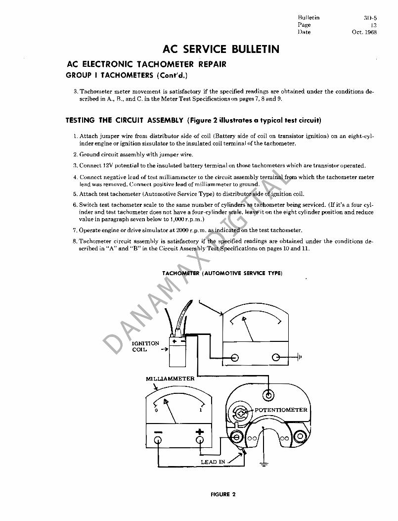
'rESTING THE CIRCUIT ASSEMBLY (Figure 2 illustrates a typical test circuit)
1. Attach jumper wire from distributor side of coil (Battery side of coil on transistor ignition) on an eight-cylinder engine or ignition simulator to the insulated coil terminal of the tachometer.
2. Ground circuit assembly with jumper wire.
3. Connect 12V potential to the insulated battery terminal on those tachometers which are transistor operated.
4. Connect negative lead of test milliammeter to the circuit assembly terminal from which the tachometer meter lead was removed. Connect positive lead of milliammeter to ground.
5. Attach test tachometer (Automotive Service Type) to distributor side of ignition coil.
6. Switch test tachometer scale to the same num ber of cylinders as tachometer being serviced. (If it's a four cylinder and test tachometer does not have a four-cylinder scale, leave it on the eight cylinder position and reduce value in paragraph seven below to 1,000 r.p.rn.)
7. Operate engine or drive simulator at 2000 r.p.rn. as indicated on the test tachometer.
8. Tachometer circuit assembly is satisfactory if the specified readings are obtained under the conditions described in "A" and "B" in the Circuit Assembly Test Specifications on pages 10 and 11.
TACHOMETER (AUTOMOTIVE SERVICE TYPE)
IGNITION COIL -+
MILLIAMMETER
FIGURE 2

Bulletin 3D-5 Page 14 Date Oct. 1968
AC SERVICE BULLETIN� AC ELECTRONIC TACHOMETER REPAIR�
GROUP I TACHOMETERS (Cont'd.)
FINAL CALIBRATION AND PERFORMANCE TESTING
1. Attach jumper wire from distributor side of coil (battery side of coil on transistor ignition) on an eight-cylinder engine or ignition simulator to the insulated coil terminal of the tachometer.
2. Connect test tachometer. (Switch scale to same number of cylinders as tachometer being serviced.)
3. Vary engine� RPM from idle to 2000 RPM. Electronic tachometer indication should be smooth throughout range of operation and comparable to the test tachometer. Adjust potentiometer at 2000 RPM if necessary.
If a simulator is being used, check tachometer performance by varying RPM from idle to 5000 RPM.
4. Seal or replace brass plug or tape on the potentiometer opening.
5. Remove tape from bezel and crimp bezel.
GROUP II TACHOMETERS
(Various Tachometers operated by AC, Permanent Magnet "P.M." generator).
APPLICATION
Diesel Engine trucks or other equipment with an engine take-off point or shaft which is used to drive the P.M. Generator.
EXPLANATION OF OPERATION
Since a Diesel engine does not employ an electrical ignition circuit, an RPM signaling and sensing device must be utilized. Thus a permanent magnet generator is engine driven, providing an alternating current (AC) signal to tachometer. This signal is rectified to direct current (DC), and is then drawn through the meter movement causing pointer deflection interpreted as the number of pulses per unit time (revolutions per minute) as the pointer moves across the calibrated dial.
TOOLS AND EQUIPMENT NEEDED FOR TACHOMETER DISASSEMBLY, REASSEMBLY, DIAGNOSIS, SERVICING AND CALIBRATION
In addition to those tools listed on page 1, the following equipment is needed.
1. Variable speed test stand (or a distributor test stand if available).
2. AC PM generator 6412848. (Available through United Motors Service.)
IDEN1'IFICATION OF TERMINALS
The output signal generated by the PM generator is connected to the one insulated terminal at rear of tachometer case.
DISASSEMBLY
1. Pry up bezel and remove bezel, glass, gaskets and suhdial. (It may be necessary to use knife edge to separate gasket from case.) Be careful not to allow metal particles to enter case.
Bulletin 3D-5 Page 15 Date Oct. 1968
AC SERVICE BULLETIN AC ELECTRONIC TACHOMETER REPAIR
GROUP II TACHOMETERS (Cont'd.)
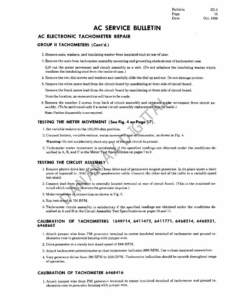
2. Remove nuts, washers, and insulating washer from insulated stud at rear of case.
3. Remove the nuts from tachometer assembly mounting and grounding studs at rear of tachometer case.
Lift out the meter movement and circuit assembly as a unit. (Do not misplace the insulating washer which insulates the insulating stud from the inside of case.)
4. Remove the two dial screws and washers and carefully slide the dial up and out. Do not damage pointer.
5. Remove the white meter lead from the circuit board by unsoldering at front side of circuit board.�
Remove the black meter lead from the circuit board by unsoldering at front side of circuit board.�
Note the location, as reconnection will have to be made.�
6. Remove� the number 2 screws from back of circuit assembly and separate meter movement from circuit assembly. (To be performed only if a meter circuit assembly replacement is to be made.)
Note: Further disassembly is not required.
'rESTING THE METER MOVEMENT (See Fig. 4 on Page 17).
1. Set variable resistor to the 100,000 ohm position.
2. Connect battery, variable resistor, meter movement and milliammeter, as shown in Fig. 4.�
Warning: Do not accidentally short any part of the test circuit to ground.�
3. Tachometer meter movement is satisfactory if the specified readings are obtained under the conditions described in A, B, and C in the Meter Test Specification on pages 7 to 9.
TESTING THE CIRCUIT ASSEMBLY
1. Remove plastic drive key (if present) from drive end of permanent magnet generator. In its place insert a short piece of (squared to .104) .130 OD speedometer cable. Connect the other end of the cable to a variable speed test stand.
2. Connect lead from� generator to centrally located terminal at rear of circuit board. (This is the insulated terminal which normally receives the generator impulse.)
3. Make remainder of connections as shown in Fig. 3.
4. Run test stand at 750 RPM.
5. Tachometer circuit assembly is satisfactory if the specified readings are obtained under the conditions described in A and B in the Circuit Assembly Test Specifications on pages 10 and 11.
CALIBRATION OF TACHOMETERS 1549714,6411472, 6411771, 6468214, 6468521, 6468662
1. Attach jumper wire from PM generator terminal to center insulated terminal of tachometer and ground tachometer case to generator housing with jumper wire.
2. Drive generator at a steady test stand speed of 1000 RPM.
3. Adjust tachometer potentiometer so that tachometer indicates 2000 RPM. Use a clean insulated screwdriver.
4. Vary generator driver from 200 RPM to 1500 RPM. Tachometer indication should be smooth throughout range of operation.
CALIBRATION OF TACHOMETER 6468416
1. Attach jumper wire from PM generator terminal to center insulated terminal of tachometer and ground tachometer case to generator housing with jumper wire.

Bulletin 3D-5 Page 16 Date Oct. 1968
AC SERVICE BULLETIN AC ELECTRONIC TACHOMETER REPAIR
GROUP" TACHOMETERS (Ccntd.)
2. Drive generator at a steady test stand speed of 2000 RPM.
3. Adjust tachometer potentiometer so that tachometer indicates 1000 RPM.
4. Vary generator drive speed to check tachometer performance. Indication should be smooth and proportional throughout the range operation.
PERFORMANCE 'rESTING THE PERMANENT MAGNET GENERATOR
The PM generator is designed for rugged, long lived performance, with no requirements for field service. Special equipment is required to charge and calibrate the special magnet. Bearings are lubricated for the lifetime of the generator. Should it be necessary to check the performance of the unit, proceed as follows:
METHOD A
1. Drive generator with a test stand operating at 1000 RPM.
2. A tachometer which is known to be calibrated and in good working order connected to output terminal of generator should indicate 2000 RPM ± 100.
METHOD B
1. Connect "+" lead from AC voltmeter (or a multimeter with selector set to measure AC voltage) to output terminal of generator. Connect"-" lead from voltmeter to frame of generator.
2. Drive generator with a test stand operating at 1000 RPM. The voltmeter should indicate 6 volts ± 5%.
Then increase test stand speed to 2000 RPM. The voltmeter should indicate 12 volts ± 5%.
3. If no voltage or tachometer indication is shown, or the value is above or below the desired figure in either test "A" or "B", the generator should be replaced.
Note: If Method"A" or "B" denotes no defect, then the vehicle should be checked for a poor ground.
GROUP III TACHOMETERS
This group consists of tachometers in which the electronic components are mounted on an insulated board.
IDEN'rIFICATION OF TACHOMETER TERMINALS
The ignition pulse is applied to the insulated coil terminal so identified. Transistor assemblies have an additional 12V terminal. Assemblies using 12V battery potential for lighting purposes have a 12V terminal marked "lamp".
On Pontiac tachometers without case, (6412411, 6412412, 6412413, 6412943, 6412944, 6468019, and 6468023), (also Chevrolet Corsa 6412203) the following rule applies:
Viewing the rear of circuit board, the insulated terminal on lower right is always the coil terminal. On transistorized assemblies, the insulated terminal on lower left is the 12V battery terminal.
DISASSEMBLY (General)
1. Pry up crimped over areas of bezel.
2. Lift off retainer, sub dial, being careful not to damage pointers.
3. Remove the nuts from the mounting and grounding studs at rear of case and lift out tachometer assembly.
4. Remove the black and the white meter leads from circuit board by unsoldering. Carefully note the position as a reconnection will have to be made.

Bulletin 3D-5 Page 17 Date Oct. 1968
AC SERVICE BULLETIN
AC ELECTRONIC TACHOMEIER REPAIR
GROUP III TACHOMETERS (Coot'd.)
5. Remove nuts from back of circuit board assembly and separate circuit board assembly from meter assembly. (To be performed only if a meter or circuit assem bly replacement is to be made.. )
Further disassembly is not recommended.
TESTING THE METER MOVEMENT (See Figure 4)
1. Set variable resistor to the 100,000 ohm position.
2. Connect battery, variable resistor, meter movement and milliammeter as shown in Fig. 4.
Warning: Do not accidentally short any part of the test circuit to ground.
METE R MOVEMENT VARIABLE
ESISTOR MILLIAMMETER
METER (
I FULL SCALE__-_
POINTER \
+/VO)T� BATTERY
BLACK METER LEAD WHITE METER LEAD
FIGURE 4
3. Tachometer meter movement is satisfactory if the specified readings are obtained under the conditions described in "A", "B" and "C" in the Meter Test Specifications on pages 7,8 and 9.
TESTING THE CIRCUIT ASSEMBLY (Figure 5 illustrates a typical test Circuit)
1. Attach jumper wire from distributor side of coil (battery side of coil on transistor ignition) on an eight cylinder engine or ignition simulator to the insulated coil terminal of tachometer.
2. Ground circuit assembly with jumper wire.
3. Connect 12V potential to the insulated battery terminal on those tachometers which are transistor operated.
4. Connect positive (+) terminal of test milliammeter to the circuit board at the connection point to which the white lead was soldered.
5. Connect negative (-) terminal of test milliammeter to the circuit board at that connection point to which the black meter lead was soldered.
6. Attach test tachometer (automotive service type) to distributor side of ignition coil.
7. Switch test tachometer scale to the same number of cylinders as tachometer being serviced.
8. Operate engine or drive simulator at 2000 RPM as indicated on test tachometer.
9. Tachometer circuit assembly is satisfactory if the specified readings are obtained under the conditions described in "A" and "B" in the Circuit Assembly Test Specifications on pages 10 and 11.

Bulletin 3D-5 Page 18 Date Oct. 1968
AC SERVICE BULLETIN� AC ELECTRONIC TACHOMETER REPAIR
GROUP III TACHOMETERS (Cont'd.)
IGNITION COIL
TACHOMETER (AUTOMOTIVE SERVICE TYPE)
LAMP
CIRCUIT BOARD ASSM.
FIGURE 5
FINAL CALIBRATION AND CHECK OUT
1. Attach jumper wire from distributor side of coil (battery side of coil on transistor ignition) on an eight cylinder engine or ignition simulator to the insulated coil terminal of tachometer.
2. Connect test tachometer. (Switch scale to same number of cylinders as tachometer being serviced.)
3. Vary engine RPM from idle to 2000 RPM. Electronic tachometer indication should be smooth throughout range of operation and comparable to the test tachometer. Adjust potentiometer at 2000 RPM if necessary.
Note: When calibrating the tachometer from the 6458484 circuit and instrument cluster assembly and 6457998 combination clock tachometer, solder the white meter lead to the "M+" location on the Tachometer circuit board. Solder the black meter lead to the "M -" location on the circuit board. Connect the heavy black wire on the circuit board to ground with a jumper wire.
If a simulator is being used, check tachometer performance by varying RPM from idle to 5000 RPM.
4. Seal or replace brass plug or tape on the potentiometer opening.
5. Remove tape from bezel and crimp bezel.
Special notes applying to tachometers in Group ill.
1. Tachometer and housing assembly 6412911 and 6412739 utilize two miniature lamps (6412563) available from United Motors Service, for lighting purposes. Should failure occur, replacement can be made as follows:
a. Cut defective bulb lead-in wires at about 1/4 inch from bulb base. b. Splice new bulb lead-ins to exposed wires and solder connections. c. Secure bulb in position with tape.
2. Due to the design of the Oldsmobile 6458484 circuit and cluster the tachometer used in this assembly will be received by the repair station with the meter separated from the circuit board. After the assembly has been serviced, unsolder the white and black meter leads, carefully pack the assembly and return to dealer.

Bulletin 3D-5 Page 19 Date Oct. 1968
AC SERVICE BULLETIN� AC ELECTRONIC TACHOMETER REPAIR
GROUP III TACHOMETERS (Cont'd.)
FINAL CALIBRATION AND CHECK OUT (Cont'd.)
3. The following wiring color codes and special notes may be used for identification purposes.
1967 Chevelle a. Light blue wire to directional signal b. Black wire to ground c. Brown wire to coil negative d. Pink wire to fused ignition e. Gray wire to lamp.
Oldsmobile Tachometer assemblies 6412911 and 6412739 a. Brown wire is the ignition terminal b. Black wire is ground c. Gray wire is the 12V lamp terminal.
Pontiac hood tachometer� '67�
a. Illumination wire is black b. Ground wire (2) is black c. Ignition wire is black and pink stripped.
'68-69 a. Illumination wire (2) is grey b. Ground wire is black c. Ignition wire is brown.
4. 1967-1968� and 1969 6-cyl. and 8-cyl. Pontiac hood tachometers can be differentiated by the fact that 6-cyl. applications are "red lined" at from 6500 to 8000 while 8-cyl. applications are "red lined" at from 5000 to 8000 RPM.
5. In rare cases water leakage complaints may develop on early production 1967 Pontiac hood tachometers. If the tachometer is being serviced for any reason, apply windshield sealing mastic to area indicated as shown in Figure 6. For 1968 and 1969 applications, follow similar procedure resealing tachometer housing.

Bulletin 3D-5 Page 20 Date Oct. 1968
GLASS LENS�
FIGURE 6

Bulletin 3D-5 Page 21 Date Oct. 1968
AC SERVICE BULLETIN AC ELECTRONIC TACHOMETER REPAIR
PART 2 (USING TC* 100 TESTER FOR TESTING AND CALIBRATION.)
General Information
The following outlined procedures differ from Part I only in that the power and signal source is from the 110 volt operated *TC 100 tester instead of a battery and ignition coil. The *TC 100 tester will not reliably test the circuit assemblies of 1965 and earlier GM original equipment breakerless ignition systems. However, it will test the meter movement of all AC tachometers.
The *TC 100 tester (see figure 7) has the following lead connections:
1. 110 Volt Power Input 2. Ground 3. Signal 4.14 Volt 5. Meter�
It has three controls:�
1. On-Off, and low voltage power switch.
2. Variable� potentiometer (except early models) by which the meter output can be varied from .10 to 1 miliampere.
3. RPM switch (by which signal frequency can be varied)-See Calibration and Check Out Chart, Page 22).
FIGURE 7
PRELIMINARY BENCH TESTING OF COMPLETE TACHOMETER
A. Connect tester-calibrator leads as follows:
*Available from LANDMESSER TOOLS CO., 980 Cass Lake Road., Pontiac, Michigan 48054.

Bulletin 3D-5 Page 22 Date Oct. 1968
AC SERVICE BULLETIN� AC ELECTRONIC TACHOMETER REPAIR
INDUCTOR TYPES See Fig. 8, Page 27.
1. Signal lead to insulated "coil" terminal or connector.
2. Ground lead to tachometer case.
TRANSISTORIZED TYPES See Fig. 9 and 10, Pages 28 and 29.
1. "Signal" lead to tachometer insulated "coil" terminal or connector.
2. "14V" lead to tachometer "BAT" terminal.
3. "Ground" lead to tachometer case.
B.� Connect to 110 volt AC supply line and turn power switch on. (Red indicator light should glow).
C.� Operate RPM selector switch from "A" thru "D" positions (if applicable) as shown in the Calibration And Check Out Chart.
D.� Observe the following:
Condition 1 - If tachometer registers proper RPM, place power switch in the "Low Voltage" position. (at position"A" and "B" only)
a.� If pointer moves down scale more than 100 RPM replace circuit assembly.
b.� If pointer remains stationary (within 100 RPM) proceed to Condition 2.
Condition 2 - If tachometer registers proper RPM or can be adjusted to proper RPM, tachometer is satisfactory. In some cases where erratic operation is suspected, allow the unit to run for several minutes and make a recheck. If performance is satisfactory, then a problem in the car wiring and/or ignition system is indicated.
Condition 3 - If tachometer reads low or is completely dead, first perform meter test, then circuit test. Replace defective component.
Condition 4� If tachometer performs erratically, perform both meter and circuit tests. Replace defective components.
CALIBRATION AND CHECK OUT CHART
Tachometer Engine Applications
Selector Engines with one 4 Cylinder 6 Cylinder 8 Cylinder Position� pos. ign. pulse/rev. 4 Cycle 4 Cycle 4 Cycle
A 3600 RPM 1800 RPM 1200 RPM 900 RPM
B 5400 RPM 3600 RPM 2700 RPM
C 6000 RPM� 4500 RPM 6300 RPMD

Bulletin 3D-5 Page 23 Date Oct. 1968
AC SERVICE BULLETIN AC ELECTRONIC TACHOMETER REPAIR
METER TEST
A.� Adjust pointer to "0" position if required.
B.� Disconnect meter lead or leads from circuit assembly.
C.� Set tester potentiometer to maximum resistance (Late model tester only).
D.� Connect tester ground lead to black meter lead and red lead from tester meter jack to the white wire on the meter. (Or meter frame if no white wire is visible.) Turn power switch "ON"-Meter should read below 1000 RPM.
+200. E.*Adjust TC 100 potentiometer so that meter indicates full scale deflection -200.
1.1/2 milliampere meters should register full scale with scribe line on potentiometer knob aligned with Blue Dot.
2. 1 milliampere meter should register full scale with scribe line on potentiometer knob aligned with Red Dot.
F.� If required, meter coil resistance can be measured with an ohmeter. It should be between 60 and 300 ohms. (Do not use RXI range as meter can be damaged by excessive current.)
Meters which cannot meet the specifications under "E" and "F" should be replaced.
CIRCUIT TEST
A. Refer to the proper circuit test illustrations as shown in Part I. Note that when the TC 100 is being used, it replaces the ignition coil and the automotive type test tachometer is not required.
B.� Connect Tester-Calibrator and Milliampere Meter leads as follows:
1. Connect signal lead to coil terminal.
2. Connect lead from 14V Jack to battery terminal if transistorized circuit assembly isbeing tested.
3. Connect ground lead to ground on circuit assembly.
4. Connect milliampere meter positive lead to ground on circuit assembly.
5. Connect milliampere meter negative lead to terminal from which black meter lead was removed.
C.� Turn RPM selector switch to position "B" for all 4, 6, or 8 cylinder engines.
D. Refer to� test specifications on pages 23-25. Circuit assemblies which cannot meet specifications should be repaired or replaced.
"Late model testers only. If early model tester is used, 1/2 milliampere meters will register full scale, 1 milliampere meters will register 1/2 scale.
CIRCUIT ASSEMBLY TEST SPECIFICATIONS USING TC 100
A. B. A. B. Adjust Make Final Adjust Make Final
Potentio- Adjustment Potentio- Adjustment meter to to provide meter to to provide
provide a a Milliam provide a a Milliam-Tachometer Milliammeter meter Tachometer Housing Milliammeter meter
Number indication of 0 indication of Number Number indication of 0 indication of
1549356 .45 .45 6412236 .39 .39 (a) 1549423 .27 .27 (b)6412292 .22 .22
1549670 .54 .54 (b)6412293 .18 .18 1549714 .90 .90 6412323 .39 .39 1549831 .39 .39 6412326 .45 .45
1549943 .45 .45 (a)6412411 .34 .34
1549980 .45 .45 (a)6412412 .34 .34
(a), (c)6411076 .23 .23 (a),(b)6412413 .34 .34
6411121 .18 .18 (a)6412426 .34 .34
6411123 .45 .45 6412504 .45 .45

Bulletin 3D-5 Page 24 Date Oct. 1968
AC SERVICE BULLETIN
AC ELECTRONIC TACHOMETER REPAIR
CIRCUIT ASSEMBLY TEST SPECIFICATIONS USING TC 100 (Cant'd.)
A. B. A. B. Adjust Make Final Adjust Make Final
Potentio- Adjustment Potentio- Adjustment meter to to provide meter to to provide
provide a a Milliam- provide a a Milliam-Tachometer Milliammeter meter Tachometer Housing Milliammeter meter
Number indication of 0- indication of Number Number indication of 0- indication of
6411124 .39 .39 6412531 .45 .45 6411238 .39 .39 6412536 .45 .45 6411241 .45 .45 (a)6412548 .39 .39 6411284 .39 .39 (a)6412549 .39 .39 6411300 .45 .45 (a),(b)6412571 .45 .45 6411316 .45 .45 (a), (b)6412572 .39 .39 6411363 .45 .45 (a)6412716 (6412739) .45 .45
(a)6411370 .34 .34 6412735 .39 .39 See Note 1 (a)6412754 (6412911) .45 .45
6411375 .68 .68 6412767 (6412759) .45 .45 See Note 1 6412774 (6412764) .39 .39
6411412 .45 .45 (b)6412778 (6412765) .45 .45 6411451 .39 .39 (b)6412782 (6412766) .39 .39 6411472 .68 .68 6412840 (6412816) .39 .39
(a)6411528 .27 .27 (b)6412844 (6412817) .39 .39 (a)6411529 .27 .27 6412911 (6412754) .45 .45 (a)6411552 .27 .27 (a)6412943 .34 .34
6411580 .45 .45 (a),(b)6412944 .34 ..34 (b)6411585 .39 .39 (a)6412983 .39 .39
6411751 .39 .39 (a), (b)6412984 .39 .39 6411752 .39 .39 6457998 .39 .39
(a)6411753 .34 .34 6458484 (Circuit & .45 .45 6411771 .77 .77 Inst, Assy.) 6411782 .45 .45 6459770 .39 .39
(a)6411826 .45 .45 (a)6468019 .34 .34 (b)6411835 .34 .34 (a),(b)6468023 .34 .34
6411857 .45 .45 6468214 .90 .90 (b)6411950 .18 .18 6468228 .54 .54 (b)6411985 .18 .18 6468270 .69 .69
6411991 .45 .45 6468285 .23 (b)6411992 .22 .22 6468319 .39 (a)6412203 .45 .45 6468320 .54 .54
6412235 ..45 .45 6468909 .39 .39 6468321 .54 .54 6468910 .39 .39 6468333 .39 .39 6468911 .39 .39 6468334 .39 .39 6468912 .39 6468336 .39 .39 6468913 .39 6468410 .34 .34 6468914 .39 6468416 .77 .77 6468938 .27 .27 6468436 .34 .34 6468939 .27 .27 6468499 .39 6468940 .27 .27 6468500 .39 6468956 .34 6468521 .68 .68 6468972 .34 6468597 .34 .34 6469100 .39 6468598 .34 .34 6469101 .39 6468662 .77 .77 6469152 .23 6468670 .39 .39 6469360 .39
6468675 .39 .39

Bulletin 3D-5 Page 25 Date Oct. 1968
AC SERVICE BULLETIN
AC ELECTRONIC TACHOMETER REPAIR
CIRCUIT ASSEMBLY TEST SPECIFICATIONS USING TC 100 (Cent'd.)
A. B. A. B. Adjust Make Final Adjust Make Final
Potentio- Adjustment Potentio- Adjustment meter to to provide meter to to provide
provide a a Milliam provide a a Milliam-Tachometer Milliammeter meter Tachometer Milliammeter meter
Number indication of 0 indication of Number indication of 0 indication of
6468695 .39 .39 6469361 .39 6468696 .39 .39 6469362 .39 6468697 .39 .39 6469381 .39 6468713 .39 6469382 .39 6468714 .39 6469383 .39 6468715 .39 6469412 .34 .34 6468821 .39 6469424 .34 .34 6468822 .39 6469478 .34 6468823 .34 6469489 .69 6468828 .54 6469499 .34 6468833 .39 6469500 .34 6468834 .34 6491312 .39 6468902 .54 6491313 .39 6468903 .54 6491314 .39
Note: Blank spaces in column "B" indicate that circuit assembly has a fixed resistor instead of a potentiometer, therefore is not adjustable. However, the circuit should provide the milliammeter specification shown in column "A".
PART 3 SERVICING OF THE CIRCUIT ASSEMBLY BY THE SIGNAL TRACING AND "REPLACEMENT OF DEFECTIVE ELECTRICAL COMPONENT" MEJHOD.
Equipment Required
1. TC 100 Tachometer Tester. 2. DC coupled oscilloscope.
Procedure
1. Connect TC 100 as outlined under "Preliminary Bench Testing of Complete Tachometer".
2. Connect oscilloscope to points A, B, C, etc. as shown in test circuit diagrams Fig 8, 9, and 10 until an improper wave shape is shown.
3. Replace the defective component found to have caused the malfunction using the parts listed in the following table.
TABLE 1
Use The Following Standard Electronic Parts (or equivalent) For Replacement Purposes.
* * *Circuit Designation
Electrical Description
Manufacturer Manufacturer's Type Number
**Ll 100 Millihenry South Haven Coil Co., Inc. 100-12
Rl 330ohms2W,10% Ohmite

Bulletin 3D-5 Page 26 Date Oct. 1968
AC SERVICE BULLETIN AC ELECTRONIC TACHOMETER REPAIR�
CIRCUIT ASSEMBLY TEST SPECIFICATIONS USING TC 100 (Cont'd.)�
•• ·Circuit Designation
R2
R3 R4 R5 R6 R7 VR1 CR1 CR2 CR3 Q1 Cl
C2
Electrical Description
1000 ohms
3.9K, 1/2W, 10% 1.8K, 1/2W, 10% 3.9K, 1/2W, 10% 680 ohms, 1/2W, 10% 3.3K, 1/2W, 10% 9.1V, 400 MW, 5% 300 V, Minature 3OOV, Minature 3OOV, Minature NPN Silicon
*MFD, zoov, 10% *MFD, 35V, 10%
.068 MFD, zoov. 10%
Manufacturer
Irc-Cts" Clarostat" or Mallory* Ohmite Ohmite Ohmite Ohmite Ohmite International Rectifier International Rectifier In ternational Rectifier International Rectifier General Electric Cornel-Dubilier Sprague Sprague
Manufacturer's Type Number
X201-10oo U39-1oo0 MTC-4-1000
IN757A� lOD3� lOD3� lOD3� 2N2714� 2P� 150D� 192P�
*Wheremore than one type is listed use the style or rating which matches the component to be replaced. **South Haven Coil, Inc., 516Williams St., South Haven, Michigan 49090. Price $.50each, minimum order $5.00.
***CircuitDesignation No.'s are to be used as part numbers on Warranty Claims. .

Bulletin 3D-5 Page 27 Date Oct. 1968
AC SERVICE BULLETIN AC ELECTRONIC TACHOMETER� REPAIR
B� o /� -. / -,
+10� r 1\ :/ ~
\ \� I- I0� oI'
I I -.5 TO-3 II5 v/cm� II .2 v/cmA I I 1/ C -, 1 :I: I 1 1/
/ ~ / '" +11
1-~
o� 0�
-1 TO-3�
5 v/cm-, I t I /� -,
--------------------~---------- ------------
L. R. C. AA I
M. 0000 v I
IGNITION COIL
+' ~
-~ ':i i-J� lMa ~VR.COIL 200.n.TER.
I
I� I,lf1 -=-� -e- IDIST. ------- -- --- ----- --------------- --- ------- ----- -------------- ------ ..... _-------- -------------- ... __ ... ---- -- --~CONTACTS
FIGURE 8� Inductor Type of Tachometer�

Bulletin 3D-5 Page 28 Date Oct. 1968
AC SERVICE BULLETIN
AC ELECTRONIC TACHOMETER REPAIR�
A B c / r'\ / 1\ / r\
+12
o
+4
o " I( 1
......
If +.7
o , \..
-, 5 v/cm I ~ I V \ 2 v/cm
I :j: I V \ .5 v /cm ' ~ I /
D E F
/ 1\ / r\ / r\
+9 r 1,-o
I II o
r 1000. -. o
I I
-6 -5
\ 5 v/cm.. / -, 2 v/cm / "\ 2 v/cm ~ /
B+ ,.- ---------- ---_ ....------- ------- -_ .. ---- --- ------ ----- -----_ ... --------- ------ ---------,
BAT. TER
IG. COIL 0
R3 CR, R
4
COIL TER
________ ............ .............. r: -::. ... :_-_... ::_ ... : "' __ ""'''
200.n.
=:. ---.I
FIGURE 9 Transistorized Type of Tachometer
used with Standard Ignition Systems

Bulletin Page Date
3D-5 29
Oct. 1968
AC SERVICE BULLETIN
AC ELECTRONIC TACHOMETER REPAIR
A B c [\. J'-.,. // / f'\
+12 +7 I I I
+.7
I\.. I\.. oo o
5 v/cm 2 v /cm .5 v /cm-, I i I V -, I i I r7 '\ I i I V o E F
/ / ~ /�
+9 Ir..... '" '"� r:~
II I-..... o o o T :1 I I
-6 -55 v/cm-, I i I / -, 2 v/cm / to - 7'\ 2 v/cm V
-----.--------:-[.-1-~~.-;-E :-- -------- ---~~-~-:: B+ -- ------------------- -- -------------------- -------------
: CfJ ~
I .R~A \ CRI.....-----+-----!--{
COIL VRTER. I
IG. COIL r R2
-e- -e- -e- ~
FIGURE 10 Transistor Type of Tachometer used with�
Transistorized (Breakerless) Ignition Systems�