Embed Size (px)
Citation preview
1536-1233 (c) 2018 IEEE. Personal use is permitted, but republication/redistribution requires IEEE permission. See http://www.ieee.org/publications_standards/publications/rights/index.html for more information.
This article has been accepted for publication in a future issue of this journal, but has not been fully edited. Content may change prior to final publication. Citation information: DOI 10.1109/TMC.2018.2815702, IEEETransactions on Mobile Computing
1
Delay Guaranteed Network Association forMobile Machines in Heterogeneous Cloud Radio
Access NetworkShao-Chou Hung, Hsiang Hsu, Shin-Ming Cheng, Qimei Cui , Kwang-Cheng Chen
Abstract —In a heterogeneous cloud radio access network (H-CRAN), which consists of multiple access points (APs) providing smallercoverage and a high power node (HPN) providing ubiquitous coverage, mobile machines can connect to multiple APs and a HPN bycoordinated multi-point transmission (CoMP) concurrently to achieve ultra-reliable and low-latency communication. However, thecurrent network association (or priorly known as handovers), which only focuses on switching between two base stations, may not bean efficient scheme in the H-CRAN. In this paper, we innovate a proactive network association mechanism by taking CoMP intoconsideration under the H-CRAN architecture. We consider two scenarios under the H-CRAN architecture: with and without theassistance of the HPN in the network. By regarding APs/HPN in the H-CRAN as resources that allocated to mobile machines, a novelproactive network association concept is proposed, and then generalized from one-to-one to multiple-to-multiple case. With theassistance of Lyapunov optimization theory, effective bandwidth and capacity theory, we can prove that this proactive networkassociation scheme can guarantee that the queueing delay performance and the delay violation probability can be both smaller than acorresponding upper bound. That is, both low-latency and ultra-reliable communication can be guaranteed. We also conductexperiments by using real trace from taxis movement data to verify the analytical results. Out results suggest the guidelines to designthe proactive network association scheme in a H-CRAN.
Index Terms —Network association, Cloud radio access network, CoMP, Robotic communication, Autonomous vehicles,Machine-to-Machine communication, Vertical handover, Internet of Things, Ultra-reliable and low-latency communication
✦
1 INTRODUCTION
The development of autonomous driving or robots has attracted in-terest due to its potential of improving traffic safety, efficiency, andinformation dissemination. Most autonomous vehicles (AVs),e.g.,Google Car [1], have been developed based on a perception sys-tem, including various on-board sensors and machine intelligenceto maneuver along the streets with other vehicles. Nevertheless,the intelligence of individual AV can be further enhanced by thenetworking and computing infrastructures of the entire intelligenttransportation systems (ITS). Due to the limitations of on-boardperception sensors, driving safety and efficiency in holistic scopeof ITS heavily rely on the reliable and low-latency wirelessnetworking toward success control information exchanges [2].
Upcoming intelligent mobile machines (IMMs) including au-tonomous and smart vehicles, unmanned aerial vehicles, robots,etc, are expected to reach the amount similar to smart phones. Withsupporting sensor and information infrastructures, current wirelessnetworking technology cannot support the traffic volume andcorresponding performance requirements, particularly networkingdelay. Furthermore, the safety of ITS highly relies on ultra-reliable
• Shao-Chou Hung and Hsiang Hsu are with the Graduate Institute ofCommunication Engineering, National Taiwan University, Taipei, TaiwanE-mail: [email protected] and [email protected]
• Shin-Ming Cheng is with National Taiwan University of Science andTechnology, Taipei, Taiwan. E-mail: [email protected]
• Qimei Cui is with the National Engineering Laboratory for Mobile Net-work Technologies, Beijing University of Posts and Telecommunications.,Beijing, China. E-mail: [email protected].
• Kwang-Cheng Chen is with the Department of Electrical Engineering, Uni-versity of South Flordia, Tampa, Flordia. E-mail: [email protected].
and low-latency communication among the vehicles and associ-ated vehicular and mobile networks. The safety-related messagesfor reliable ITS demand strict networking requirements. Accord-ing to [3], the delay performance of safety-related messagesshould be no more than50 ∼ 100ms. For massive operation ofautonomous vehicles, it is widely believed that a further stringentend-to-end latency in the order of1ms is necessary [4]. To achieveultra-reliable and low-latency communication in ITS, there are twomajor technology challenges to overcome: (1) Spectrum scarcityand (2) Network association of low delay guarantees.
• Spectrum scarcity: From GSM/GPSR, UMTS toLTE/LTE-A, data transmission rate has been enhanced toa million fold solely by connecting to a powerful widelybase stations (BSs). With the development of physicallayer technology such as MIMO, beamforming, it seemslike that transmission rate has almost approached Shannonbound and cannot be improved largely [5]. To solvethis challenge by small-cell ultra-dense networking, thearchitecture of heterogeneous cloud radio access network(H-CRAN) was proposed as shown in Fig. 1. In general,there are two major tiers of networks under H-CRANarchiecture. The first tier is composed of high power node(HPN), which traditionally can provide the ubiquitousservices of the IMMs. The second tier is composed of agroup of distributed low power APs in the service area ofthe HPN. By decreasing the distance between IMMs andAPs, the spectrum efficiency and transmission rate can besuccessfully improved [6].
• Network association: The smaller transmission distance

1536-1233 (c) 2018 IEEE. Personal use is permitted, but republication/redistribution requires IEEE permission. See http://www.ieee.org/publications_standards/publications/rights/index.html for more information.
This article has been accepted for publication in a future issue of this journal, but has not been fully edited. Content may change prior to final publication. Citation information: DOI 10.1109/TMC.2018.2815702, IEEETransactions on Mobile Computing
2
HPNHPN and APs form
the virtual cell
BBUs
Distributed
APs
Internet
Vertical Network
AssociationHorizontal Network
Association
Backhual
Fronthual
Mobile Machines
Fig. 1: H-CRAN based air interface architecture.
BS BS
Handover Region
(a)
Handover Region
(b)
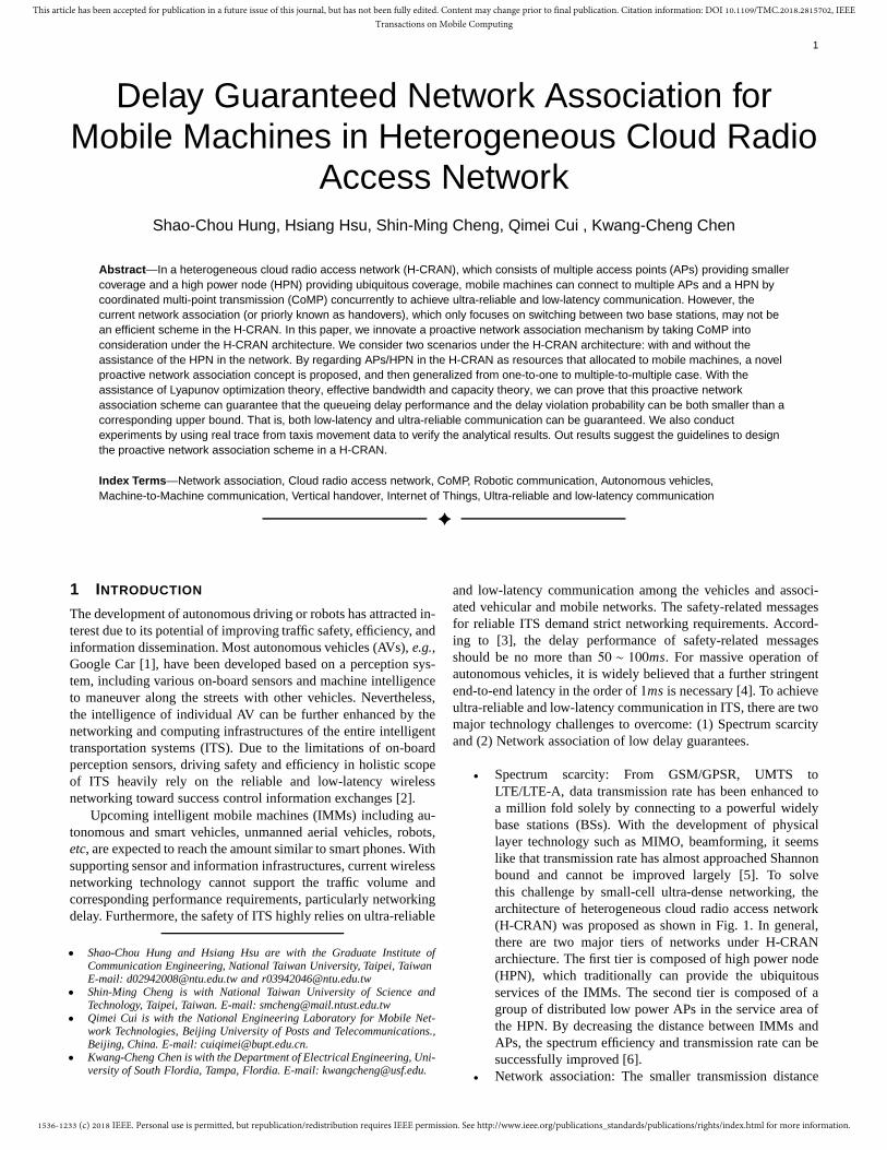
Fig. 2: a) The conventional handover in a homogeneous network.b) Frequent handover in the heterogeneous networks.
in H-CRAN architecture suffers from frequent networkassociation (also known as user association or handover).As shown in Fig. 2, conventional network associationsonly happen at the edge of a BS coverage. However, underthe H-CRAN architecture, there are many distributed APsand each of them has a smaller service region than thecoverage of a conventional BS. The edge of the networksare any-where. Under this scenario, to prevent from thenetwork being occupied by control signals, it is necessaryto coordinate the small cell networks to execute a newhandover scheme [7]. Therefore, the concept ofvirtualcell is proposed to solve this problem. It is achieved byconnecting all distributed APs (or called remote radiohead) and HPN with the Baseband Units (BBUs) to createa large cell virtually, and all the radio resources in this“large” cell is scheduled and allocated by utilizing thecloud computing technology [8]. In this case, the differentAPs are transparent to the IMMs. The number of networkassociations is successfully reduced.
In order to fully take advantage of the distributed APs, co-ordinated multi-point transmission (CoMP) has been consideredas an important technique in H-CRAN [9] within virtual cell. Inthis case, all the distributed APs behave as the remote antennas,and are allowable to service one IMM simultaneously. The datacollected from these remote antennas can be processed at BBUin a centralized way. It is intuitive for the IMMs to build moreconnections to the APs or the HPN to pursue much better transmis-sion performance. However, the more connections with the APs,the larger number of signalling overheads might be incurred. For
example, the signaling overhead due to synchronization amongAPs in the same virtual cell might become terrible burdens tomeet the delay requirements [10]. On the other hand, connectingwith all the available APs may incur unfairness issue. Considerthat an IMM occupies all the available APs, a later coming IMMsuffering from deep fading or severe interference may not obtainenough APs. The delay performance thus cannot be guaranteed.As a result, the number of utilized APs should also be optimized.
The goal of this paper is to design a delay-aware “vehicle”-centric approach to fully utilize the advantages of CoMP andsimultaneously prevent the resulting control signal overheads tohurt the delay performance, such that ultra-low latency end-to-end wireless networking can be realized. A novel proactivenetwork association mechanism is proposed to enable effectiveradio resource utilization by taking fairness and control signaloverheads into consideration. We focus on guaranteeing the delayperformance with only “enough” utilization number of APs andthus the control signal overheads can be minimized. In addition,comparing with the network association in a conventional one-tiernetwork consisting of only BSs, network association in H-CRANwith two-tier architecture becomes more complicated. The IMMsmight coordinate with the multiple APs (known as the horizontalnetwork association) or connect to the HPN (known as verticalnetwork association) and the APs concurrently. The transmissionquality of the IMMs is highly relative to the number of APsbeing connected to and whether the IMMs have a connectionto the HPN or not. Therefore, the network associations in H-CRAN become a process of allocation involved the distributedAPs and HPN. In other words, we can regard these distributed APsand HPN as the limited cherish resource in H-CRAN and IMMscan proactively access such “resources” to improve their delayperformance. Different from conventional approach, switchingfrom one BS to another BS (one-to-one scenario), the proposedproactive network association thus becomes a multiple-to-multiplescenario,i.e., IMMs switch from a set of APs to another set ofAPs.
We discuss two different scenarios in H-CRAN: with and with-out the assistance of the HPN. In the scenario without HPN, theIMMs cannot access to the HPN and only rely on the distributedAPs. The goal is to design a proactive network association schemethat can minimize the number of the utilized APs by the IMMs butsimultaneously guarantee the delay requirements. It is not onlyfor decrease the complexity of decoding CoMP signal but also todecrease the burden on the backhaul network [11]. In the scenariowith HPN, an IMM can make a decision whether to connect toHPN for better service or not. In this scenario, the utilization ofHPN is minimized under the constraint of guaranteeing the delayperformance. The first reason is to avoid additional informationexchanges like authentication, which may further hurt the delayperformance. Another reason is for keeping the infrastructuresfor emergency accident. Due to being able to provide ubiquitousservice, HPNs should be reserved to those IMMs suffering fromserious delay or emergencies like, car crash. Therefore, the designgoal is to treat HPN as a supplementary infrastructure by mini-mizing utilization to achieve the delay guarantees.
With the high speed mobility, the number of available APsfor an IMM changes faster than the conventional user equipmentsexperiences. The conventional static optimization approach thussuffers from the out-of-date information and the performancecannot be optimized. Therefore, two time-dynamic optimizationproblems are formulated for two different scenarios to solve the
1536-1233 (c) 2018 IEEE. Personal use is permitted, but republication/redistribution requires IEEE permission. See http://www.ieee.org/publications_standards/publications/rights/index.html for more information.
This article has been accepted for publication in a future issue of this journal, but has not been fully edited. Content may change prior to final publication. Citation information: DOI 10.1109/TMC.2018.2815702, IEEETransactions on Mobile Computing
3
proactive network association in H-CRAN. The algorithms arealso proposed to solve the corresponding dynamic optimizationproblems in the corresponding scenario. With the assistance ofLyapunov optimization theory, we can analyze the delay perfor-mance of the proposed algorithm. The proposed algorithm can alsobe proved to approach the best-tradeoff solution for the proposeddynamic optimization problem.
The rest of the paper is organized as follows: The relatedworks are in Section 2. Section 3 describes the details of ourmodel. In Section 4, we formulate the dynamic optimization forthe proactive network association without the help of verticalassociation. The dynamic optimization for vertical association isdescribed in Section 5. The delay violation probability is analyzedin Section 6. In Section 7, the design guideline for the horizontaland vertical network association are provided. The simulationresults of the proposed algorithm are provided in Section 8.
2 L ITERATURE REVIEWS
In this section, we first revisit the literatures about data offloadingin heterogeneous networks and CoMP clustering to reveal ourunique contribution. Intuitively, the device makes a network as-sociation decision according to the radio link quality,i.e., receivedsignal strength (RSS) or signal-to-interference-plus-noise (SINR).Actually, this approach is also commonly used in the handoverscheme of the traditional homogeneous networks [12]. However,with the amount of the IMMs increasing, solely selecting thenetwork with the best link may not be a suitable strategy. For ex-ample, [13] points out that the users’ quality of experiences (QoE)depends not solely on the SINR but also the other competitors andthe corresponding allocated resource.
2.1 Data Offloading
To increase the performance of the whole systems, we can solvethe network association from the viewpoints of loading balancingbetween different tiers of heterogeneous networks. That is, theusers can be associated to multiple networks to decrease theloading of HPNs and fully utilize the unused resource in the smallcells, andvice versa. Generally speaking, the current studies ondata offloading focus on optimizing the system performance by acentralized [14]–[17] or a distributed [18]–[20] approach.
In [14], the load balancing scheme is designed based on thelong-term throughput of users to find the best associations betweenHPNs and users. To decrease the network-wide average packetdelay, the user association and corresponding resource allocationscheme are designed based on experiencing packet delay in [15].In [16], the mobility model is taken into consideration. Basedon the proposed mobility model, a Markovian-based approach isproposed to do data offloading. Energy consumption and networkcapacity are further improved. Data offloading gain in terms ofdelay performance is analyzed in [17]. In this works, the WiFinetworks are regarded as the small cell networks utilizing theorthogonal radio resource to the HPN. Wifi networks are consid-ered as small cell networks utilizing orthogonal radio resources toHPN. For distributed approaches, game theory is a popular tool todesign a distributed strategy among different players (networks).In [18], a data offloading scheme based on the Stackelberg gameand the corresponding efficient algorithm to find the best strategyare proposed. To measure the fairness between different networklayers, a coalitional game is formed to encourage the cooperationbetween different layer networks in [19]. To fully utilize the
unused capacity, an auction-based mechanism is proposed toencourage non-busy WiFis to release the resource and decreasethe burden of HPN in [20].
2.2 CoMP Clustering
It is known of advantages to utilize CoMP in the heterogeneousnetworks. However, the success of CoMP relies on the coor-dination between all small APs including the synchronizationissue [21], exchanges of channel state information [22], andadditional signal processing for interference mitigation [23],etc.Consequently, in order to reduce these overhead, a question calledCoMP clustering arise: how small a CoMP can be but still providethe major portion of the potential CoMP performance. User-centricapproach is considered in [24], [25], where the clustering of theCoMP is dynamic according to the users. In [26], the user-centricapproach is also proposed to maximize the average throughput ofthe network. Different from previous two, the limitation of thebackhaul networks is considered. In [27], based on coalition gametheory, a distributed clustering algorithm is proposed. The clustersize can automatically increase to the predefined cluster size andoptimize the performance.
The previous works about data offloading assume that theIMMs can be served by only one HPN or AP. The IMMs are lim-ited to switch from one HPN to another one. With the developmentof CoMP, the IMMs can connect to multiple APs simultaneouslyand a new network association should be developed. On the otherhand, for the previous work about CoMP clustering, they focus onthe optimize the performance with minimizing the size of CoMPnetwork in the same tier. However, there still lacks method ofCoMP clustering with assistance from HPN in a heterogeneousnetwork. In this work, we tackle the network association fromthe viewpoint of minimizing the number of the utilized APs,i.e.,the size of CoMP. With vertical network association, a HPN canbe regarded as an auxiliary tool. An IMM offloads data to a HPNwhen APs cannot satisfy service requirements. By this manner, wesave more control signals to coordinate multiple APs to operateCoMP and the delay can be further improved.
We summarize our contribution as follows.
• A proactive horizontal network association is proposed tominimize the control signal cost of CoMP.
• A proactive vertical network association is proposed tofully integrate the APs and HPN networks.
• The proposed approach can only utilize “enough” APs orHPN to achieve the delay performance requirements.
3 SYSTEM MODEL
3.1 The Cost of Network Connection
As mentioned before, the control signal overheads have a great im-pact on the delay performance. Therefore, it is necessary to knowthe time costs of horizontal and vertical associations carefully. Weprovide a brief discussion about what kind of time cost is neededin the following respectively. We refer to [28], [29] for the detailsnumerical values of these time costs.
During the process of a horizontal network association, thefollowing steps are required. First, it takes sensing delay (dsen)to identify the available APs in its transmission region. Then, anIMM spends additional time to inform the core network aboutits connection requirement (dIMM
inform). Subsequently, BBUs pooldetermines one or multiple appropriate APs to allocate a channel

1536-1233 (c) 2018 IEEE. Personal use is permitted, but republication/redistribution requires IEEE permission. See http://www.ieee.org/publications_standards/publications/rights/index.html for more information.
This article has been accepted for publication in a future issue of this journal, but has not been fully edited. Content may change prior to final publication. Citation information: DOI 10.1109/TMC.2018.2815702, IEEETransactions on Mobile Computing
4
TABLE 1: Glossary of Notations.
Notation Description
J Number of independent channels shared by APs.λM Distribution density of IMMs.λap Distribution density of APs.P0 Transmission power of IMMs.v Velocity of IMMs.θ Non-outageSINR threshold.α Path-loss exponent.d Distance between an IMM and an AP.R Radius of the transmission region of IMMs and APs.Gj Channel fading of an IMM in thejth channel.Gx j Channel fading of thexth IMMs as an interference
source injth channel.p Non-outage probability of each channel.Pav Probability of the AP being available for the
arrival IMMs.Pvi Delay violation probability.aA(t) In the scenario with vertical handover,aA(t) refers to
the data go through APs.Pchoose Probability that an AP is selected by an IMM.Pav Probability that not allJ channels of an AP are
occupied.N (t) Number of available APs at time slott
to the IMM (dBBU). If this allocated channel is the same withcurrent one used by the IMM, the IMM just transmits dataas previously. There is no further control information exchangeneeded between the IMM and the core network. The resultingtotal delay is
Dchansame= dsen+ dIMM
inform+ dBBU.
However, if the same channel in the newly designated AP has beenallocated, this AP can immediately allocate the other channel tothe IMM. In such case, the network needs to spend additional timeto inform the IMM which channel is allocated to (dNet
inform). Then,the IMM switches to the newly designated channel and resumethe transmission after synchronization with multiple APs (dsyn)for CoMP. Then the resulting total delay is
Dchandiff = dsen+ dIMM
inform+ dBBU + dNetinform+ dsyn.
BecausedNetinform and dsyn are two additional delays, to speed up
association for low delay, it is better for the whole network tooperate horizontal associations in the same channel as long aspossible. Therefore, it is reasonable to assume that the networksalways manage the horizontal association in the same channel.
An IMM can proceed vertical network association with aHPN. The vertical association involves further more complicatedprocedures between the IMM and the network. These additionalprocedures includes: (1) the sensing delay to find the existing HPN(dver
sen) (2) the IMM informs the core network the requirements ofbuilding a vertical connection (dver
inform) (3) the processing time inthe BBU to coordinate the unoccupied channels (dHPN) of theHPN (4) the time to inform the IMM about the allocated channel(dNet
inform) (5) the synchronization time between the IMM and theHPN and APs (dver
syn). Therefore, the total delayDver is
Dver = dversen+ dver
inform+ dHPN+ dNetinform+ dver
syn.
On the other hand, due to the limited number of channels in aHPN, the BBUs may terminate the vertical connection with anIMM. This termination also introduces additional control signalsto the network. To minimize the utilization rate of a HPN, it isnot only the reason that these additional delay caused by verticalassociation but also these additional exchanges of control signals.
HPN AP
Intelligent
Mobile
Machine
Vertical Association Link
Horizontal Association Link
BBUs
Fronthual
R
Data Queue
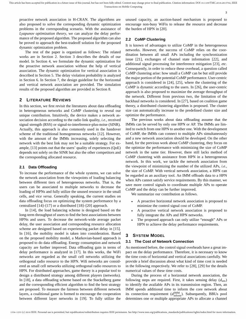
Fig. 3: Illustration of the network system architecture.
Therefore, it is necessary to design a new association scheme todecrease the utilization rate ofvertical association.
3.2 Network Model
As shown in Fig. 3, the H-CRAN is composed of IMMs, a HPN,small APs and BBUs. The BBUs pool in the H-CRAN is in chargeof collecting information and do the signal processing [9]. Thereare two possible paths in the air for the IMMs connecting tothe network infrastructure. The first one is to build horizontalconnections with the AP networks. We assume that there areJ different channels shared by the AP networks. Each AP (ormultiple APs with CoMP technique) can allocate one of theJchannels to the IMMs in its service region. The IMMs can connectto the network with one or multiple APs through one of theseJ channels. The second one is a vertical connection with theHPN network. Here, we assume that the channel of horizontal andvertical air interface are orthogonal thus no cross-tier interferencebetween the HPN and the APs networks.
To consider a general case, we take advantage of randommodeling for the IMMs and the APs via the Poisson point process(PPP) model. The spatial distribution of the IMMs follows a PPPwith density λM and its transmission power is denoted asP0.Without loss of generality, we assume that each IMM is movingalong the straight line with a velocityv(meters/s) and differentdirection randomly during the need of network association orhandover. The spatial distribution of the APs also follows PPPwith densityλap . The IMMs can build the connections with theAPs within a radiusR through one or multiple ofJ channels. Weassume that the packet can be transmitted successfully if theSIRj
value, the signal-to-interferenceratio in thejth channel, is largerthan θ. Then the non-outage probabilityp j in the jth channel isdefined as
p j , P(SIRj ≥ θ). (1)
The signal-to-interference ratioSIRj in the jth channel is
SIRj ,P0G jR−α
Ij(2)
whereIj is denoted as the total interference in thejth channel,αis the coefficient of path loss subject to environment, andG j is thechannel fading following exponential distribution with unit mean.Here, we ignore the effect of white noise due to strong interferencefrom other IMMs.

1536-1233 (c) 2018 IEEE. Personal use is permitted, but republication/redistribution requires IEEE permission. See http://www.ieee.org/publications_standards/publications/rights/index.html for more information.
This article has been accepted for publication in a future issue of this journal, but has not been fully edited. Content may change prior to final publication. Citation information: DOI 10.1109/TMC.2018.2815702, IEEETransactions on Mobile Computing
5
The interferenceIj comes from the other IMMs also utilizingthe jth channel. Here, we assume that all the APs randomlyallocate a channel to each IMM. Therefore, the point process ofthe IMMs in thejth channels, denoted asΦj , is another PPP. Then,the interference in thejth channel can be expressed as
Ij =∑
x∈Φ j
P0Gx j R−αx , (3)
where Gx j is the channel fading from thexth IMM in the jthchannel.
Here, we assume that all the IMMs choose the APs randomly.We also assume that, after an IMM connects to a set of APs, theBBUs pool or AP itself will allocates one channel to the IMMrandomly. Therefore, the IMM’s distribution density in thejthchannel isλj = λM/J. Then the non-outage probabilityp j of thetransmission link injth channel can be further expressed as [30]
p j (d) = P(SIRj ≥ θ
)
= EIj
[P
(G j ≥
θIjP0d−α
)]
= exp
[−λM
Jθ2/αd2 2π2
α sin(2π/α)
],
(4)
where d is the distance between the IMM and AP. Due tothe assumption that the IMMs choose the APs within radiusRrandomly, the distance between an IMM and an APr is also arandom variable with the distributionr ∼ 2r/R2. The non-outageprobability p j can be further expressed as
p = Ed(p j (d))
=
∫ R
r=0
p j (r)2r
R2dr
=
1− exp(−ξR2
)
ξR2,
(5)
whereξ = λM
Jθ2/α 2π2
α sin(2π/α), which is actually the average number
of available APs. We can find that the non-outage probability isthe same in each channel. Therefore, non-outage probability inevery channel is denoted asp, i.e., p j = p,∀ j ∈ J.
3.3 Queue Model for Device Mobility
Under the H-CRAN architecture with CoMP technique, dataservice rate of the IMMs depends on the available APs in thetransmission region. The BBUs can allocate the available APs tothe IMMs and thus control the data service rate. To describe thesolution space of the proposed dynamic optimization and analyzethe performance of the proposed scheme in the later section, itis necessary to find the probability distribution of the availableAPs around the IMMs. By the stationary characteristics of ahomogeneous PPP, the statistics measured by a typical IMM atthe origin is representative of all the others [31]. In the following,we consider a typical AP and IMM to represent all the others inthe network.
3.3.1 Probability of APs Being Available
From the viewpoint of the AP, the IMMs enter into a circulartransmission region centering at the AP with a radiusR andare serviced by the AP until they leave the transmission region.Because the AP has onlyJ channels, therefore, the number of theIMMs in the AP at each time slot can be modeled as a queuewith J servers. Due to Poisson distribution of the IMMs, this
queue can be regarded as aM/G/J/J queue.J/J comes fromthe fact that each ofJ channels can serve only one IMM. Theservice time of an IMM is a duration of staying in the transmissionregion of the AP. The expected service time isπR
2vas shown
in Appendix B. The arrival rate of this queue is a rate that theIMM enters into the transmission region of the AP. It can beexpressed as2RvλMPchoose as shown in Appendix B. The reasonof Pchoose is that the IMM may have multiple connectible APssimultaneously. We assume that the IMM randomly selects one ofthe connectible APs to establish a connection link.Pchoose can befurther expressed as
Pchoose =
∞∑
k=1
pn=k1
k, (6)
wherepn=k is the probability that there arek APs in its transmis-sion region of the IMM. It can be expressed as
pn=k = P (k possible APs|k ≥ 1)
=
e−λap πR2(λapπR2)k
k!
/∞∑
i=1
e−λap πR2(λapπR2)n
n!,
(7)
and 1k
in (6) comes from that the IMM randomly selects one APamongk connectible APs to establish a connection link.
To derive the probability of an AP being available,i.e., notall the J channels are occupied by the IMMs, we need to knowthe probability distribution of the number of occupied server inthe M/G/J/J queue. According to queueing theory, it can bedescribed byErlang B formula [32]. We denote the probability ofthe AP being available asPav , then it can be expressed as
Pav = P (not all server being occupied)
= 1−ρJ/J!
∑Jj=0 ρ
j/ j!,
(8)
whereρ= πR2λMPchoose is the utilization factor of a queue. Here,we need to note that it is an upper bound of the real probabilityof the APs being available because the IMMs may access multipleAPs at the same time, which results in largerPchoose and thussmallerPav .
3.3.2 Probability Distribution of Available APs for IMMsIn this subsection, we will derive the probability distribution ofthe number of available APs from the viewpoint of an IMM. Wedenote the number of available APs within the radiusR centered atthe IMM asN(t). Due to high mobility,N(t) is a random variableat each time slott. The update rule ofN(t) can be expressed as
N(t +1) =max[N(t)−Nl(t),0]+Na(t), (9)
whereNl(t) and Na(t) is the number of APs leaving and arrivingthe transmission region of the IMM. We can find that this is aclassical form of a dynamic queue. Because there is no restrictionon N(t), the number of available APs in the transmission regionof the IMM can be modeled as aM/G/∞. With a velocityv, theexpectation ofNa(t) is 2RvλapPav and the proof is similar to theone in Appendix B. The expectation service time of this queue,i.e., the expected duration of an AP staying in the transmissionregion of the IMM is πR
2v, which can be derived by the similar
steps in Appendix B. According to the transition behavior of aM/G/∞ queue, the probability distribution ofN(t) is
P(N(t) = n) =e−Nav Nn
av
n!, (10)
whereNav = πR2λapPav is the average number of available APs.
1536-1233 (c) 2018 IEEE. Personal use is permitted, but republication/redistribution requires IEEE permission. See http://www.ieee.org/publications_standards/publications/rights/index.html for more information.
This article has been accepted for publication in a future issue of this journal, but has not been fully edited. Content may change prior to final publication. Citation information: DOI 10.1109/TMC.2018.2815702, IEEETransactions on Mobile Computing
6
3.4 Queueing Model of Data
To describe the dynamics of the queue in a typical IMM, we definethe data queueU(t) as the untransmitted data in the typical IMMat each time slott. The queueU(t) evolves according to
U(t+1) =max [U(t)−u(t),0]+a(t), (11)
whereu(t) anda(t) is the number of successfully transmitted andthe arriving packets at the time slott. The dynamic update rule in(11) satisfies following lemma which is useful while we analyzethe performance of our proposed network association.
Lemma 1. For positive real numbersX,Y, µ, υ satisfying
Y =max[X − µ,0]+υ,
then the following inequality holds [33]
Y 2 ≤ X2+ µ2+υ2 −2X(µ−υ). (12)
At each time slott, the service rate of the IMM is determinedby the number of accessed APs. The decision space of the IMMis denoted asDt :
Dt =
{{1, . . .,N(t)}, if N(t) , 0
{0}, if N(t) = 0,(13)
whereN(t) is the total available accessible AP at time slott andn(t) ∈ Dt is denoted as the number of connected APs at the timeslot t.
Because an IMM can connect to one or multiple APs in thesame channel simultaneously, the capacity of the transmission linkcan be regarded as a single-input-multiple-output (SIMO) channel.The capacity of SIMO withn(t) accessed APs can be expressedas log(1+
∑n(t)
i=1SIRi). It means that the summation ofSIRs at
different links determines whether the outage happens or not.Therefore, thepn(t) non-outage probability withn(t) APs at timeslot t can be expressed as
pn(t) = P(n(t)∑
i=1
SIRi ≥ θ)
≅ 1−P(SIRi < θ)n(t)
= 1−(1− p)n(t),
(14)
Because only one packet is transmitted in each time slot, thentheu(t) can be expressed as
u(t) =
1, ifn(t)∑
i=1
SIRi ≥ θ
0, ifn(t)∑
i=1
< θ.
Combing with (14), the mean number of serviced packets at timet condition with a decisionn(t) is
E(u(t)|n(t)) = 1−(1− p)n(t) . (15)
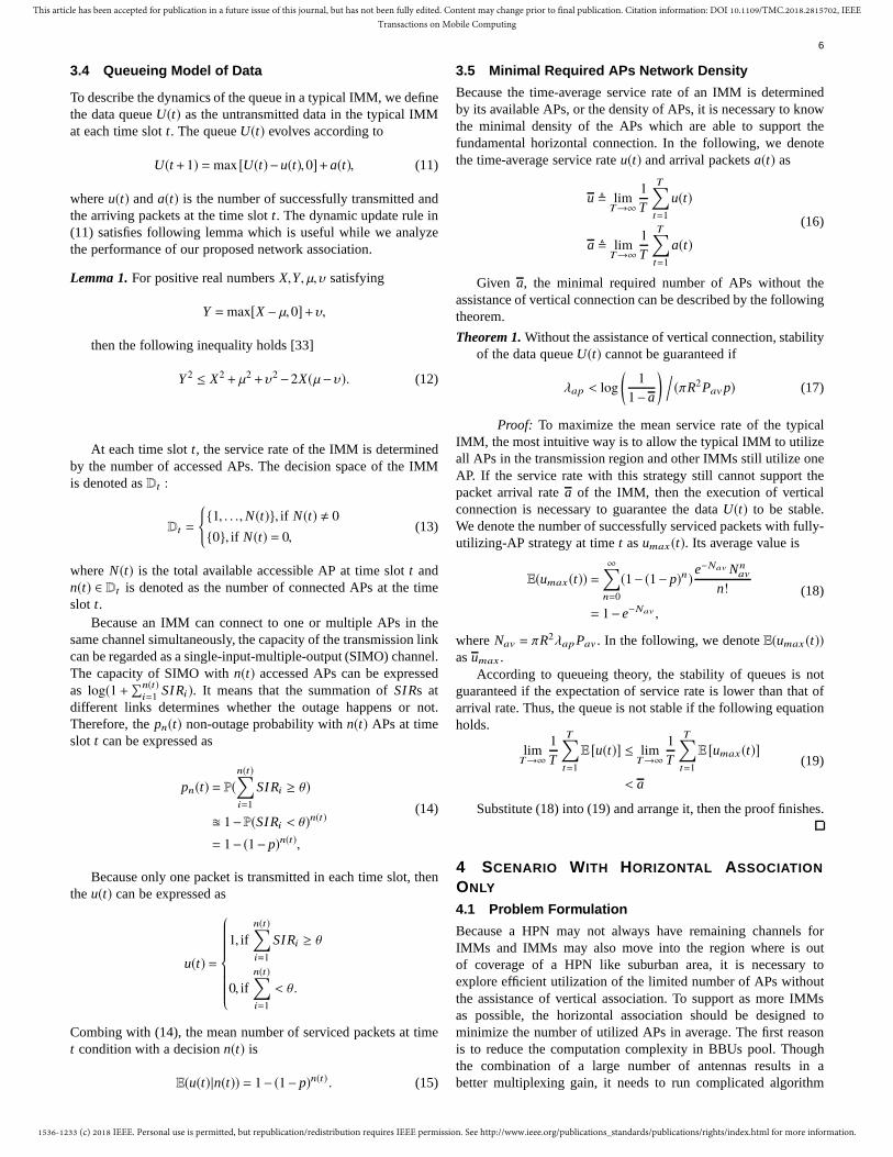
3.5 Minimal Required APs Network Density
Because the time-average service rate of an IMM is determinedby its available APs, or the density of APs, it is necessary to knowthe minimal density of the APs which are able to support thefundamental horizontal connection. In the following, we denotethe time-average service rateu(t) and arrival packetsa(t) as
u , limT→∞
1
T
T∑
t=1
u(t)
a , limT→∞
1
T
T∑
t=1
a(t)
(16)
Given a, the minimal required number of APs without theassistance of vertical connection can be described by the followingtheorem.
Theorem 1. Without the assistance of vertical connection, stabilityof the data queueU(t) cannot be guaranteed if
λap < log
(1
1−a
) /(πR2Pavp) (17)
Proof: To maximize the mean service rate of the typicalIMM, the most intuitive way is to allow the typical IMM to utilizeall APs in the transmission region and other IMMs still utilize oneAP. If the service rate with this strategy still cannot support thepacket arrival ratea of the IMM, then the execution of verticalconnection is necessary to guarantee the dataU(t) to be stable.We denote the number of successfully serviced packets with fully-utilizing-AP strategy at timet asumax(t). Its average value is
E(umax(t)) =∞∑
n=0
(1−(1− p)n)e−Nav Nn
av
n!
= 1− e−Nav ,
(18)
whereNav = πR2λapPav . In the following, we denoteE(umax (t))asumax .
According to queueing theory, the stability of queues is notguaranteed if the expectation of service rate is lower than that ofarrival rate. Thus, the queue is not stable if the following equationholds.
limT→∞
1
T
T∑
t=1
E [u(t)] ≤ limT→∞
1
T
T∑
t=1
E [umax(t)]
< a
(19)
Substitute (18) into (19) and arrange it, then the proof finishes.
4 SCENARIO WITH HORIZONTAL ASSOCIATION
ONLY
4.1 Problem Formulation
Because a HPN may not always have remaining channels forIMMs and IMMs may also move into the region where is outof coverage of a HPN like suburban area, it is necessary toexplore efficient utilization of the limited number of APs withoutthe assistance of vertical association. To support as more IMMsas possible, the horizontal association should be designed tominimize the number of utilized APs in average. The first reasonis to reduce the computation complexity in BBUs pool. Thoughthe combination of a large number of antennas results in abetter multiplexing gain, it needs to run complicated algorithm
1536-1233 (c) 2018 IEEE. Personal use is permitted, but republication/redistribution requires IEEE permission. See http://www.ieee.org/publications_standards/publications/rights/index.html for more information.
This article has been accepted for publication in a future issue of this journal, but has not been fully edited. Content may change prior to final publication. Citation information: DOI 10.1109/TMC.2018.2815702, IEEETransactions on Mobile Computing
7
like successive interference cancellation to decode the signals.Second, more connected APs may increase the backhual load.In an uplink scenario, all the received signal must be forwardedto the combination point like BBUs pool to decode the signals.To decrease the burden on backhual networks, the desired numberof connected APs should be just enough. On the other hand, asmentioned in the Section 3.1, an association scheme involves morecontrol signal exchanges between not only IMMs and APs but alsocore networks. Also, decreasing the utilization number of APs canhelp to leave more available APs for other IMMs which may sufferfrom some emergency like car crash.
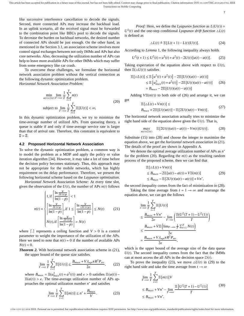
To overcome these challenges, we formulate the horizontalnetwork association problem without the vertical connection asthe following dynamic optimization problem.Horizontal Network Association Problem:
minn(t)∈D(t)
limT→∞
1
T
T∑
t=1
n(t)
subject to limT→∞
1
T
T∑
t=1
E [U(t)] <∞,
(20)
In this dynamic optimization problem, we try to minimize thetime-average number of utilized APs. From queueing theory, aqueue is stable if and only if time-average service rate is largerthan that of arrival rate. Therefore, this constraint is equivalent tou > a.
4.2 Proposed Horizontal Network Association
To solve the dynamic optimization problem, a common way isto model the problem as a MDP and apply the policy or valueiteration algorithm [34]. However, it may take a lot of time beforethe decision policy becomes stationary. Thus, this approach maynot be appropriate for the mobile networks, which has highlyrequirement on the delay performance. Therefore, we present thefollowing horizontal scheme based on theLaypunov optimization.
Horizontal Network Association Scheme: At every time slot,given the observation of theU(t), the number of APsn(t) follows
n(t) =
1, if
⌈ln V
2U(t)p
ln(1− p)
⌉
< 1
⌈ln V
2U(t)p
ln(1− p)
⌉
, if 1 ≤
⌈ln V
(2U(t)p)
ln(1− p)
⌉
≤ N(t)
N(t), if
⌈ln V
2U(t)p
ln(1− p)
⌉
> N(t)
(21)
where ⌈.⌉ represents a ceiling function andV > 0 is a controlparameter to weight the importance of the utilization of the APs.Here we need to note thatn(t) = 0 if the number of available APsN(t) = 0.Theorem 2. With horizontal network association scheme in (21),
the upper bound of the queue size satisfies
limT→∞
1
T
T∑
t=1
E [U(t)] ≤Bmax +VλapπR2Pav
2ǫ, (22)
whereBmax = E(u2max(t)+ a2(t)) andǫ > 0 satisfiesE (u(t)) −
E(a(t)) > ǫ . The time-average utilization number of APs ap-proaches the optimal utilization numbern∗ and satisfies
limT→∞
1
T
T∑
t=1
E [n(t)] ≤ n∗+Bmax
V. (23)
Proof: Here, we define theLyapunov function asL(U(t)) =U2(t) and the one-step conditionalLyapunov drift function △L(t)is defined as
△L(t) , E [L(t +1)− L(t)|U(t)] . (24)
According toLemma 1, the following inequality always holds
U2(t +1) ≤ U2(t)+u2(t)+a2(t)−2U(t) [u(t)−a(t)] . (25)
Taking expectation of the equation above with respect toU(t),thenE(△U(t)) satisfies
E [△L(t)] ≤ E[u2(t)+a2(t)
]−2E [U(t)(u(t)−a(t))]
≤ E[u2max(t)+a2(t)
]−2E [U(t)(u(t)−a(t))]
= Bmax −2E [U(t)(u(t)−a(t))]
(26)
Adding VE(n(t)) to both side of (26) and arrange it, we canget
E [△L(t)+Vn(t)] ≤
Bmax +2E [U(t)a(t)] −E [2U(t)u(t)−Vn(t)] .(27)
The horizontal network association actually tries to minimize theright hand side of the equation above given theU(t). That is,
maxn(t)∈D(t)
E [2U(t)(u(t)−a(t))−Vn(t)|U(t)] . (28)
Substitute (15) into (28) and choose the integer to maximize theequation above, we get thehorizontal network association in (21).The details of the proof are shown in Appendix A.
We denote the optimal average utilization number of APs asn∗
for the problem (20). Regarding then(t) as the resulting randomprocess of the proposed scheme, then we can find that
E [△L(t)+Vn(t)]
≤ Bmax −2E [u(t)−a(t))+VE(n(t)]
≤ Bmax −E [2U(t)(u(t)−a(t))]+Vn∗,
(29)
the second inequality comes from the fact of minimization in (28).Taking the time average fromt = 1 → ∞ and rearrange the
equation above, we can get the follows
limt→∞
1
T
T∑
t=1
E [U(t)]
≤Bmax +Vn∗
2ǫ− lim
T→∞
(E(U2(T +1)−U2(1))
T
)
≤Bmax +VE
(limT→∞
1T
∑Tt=1 N(t)
)
2ǫ
=
Bmax +VλapπR2Pav
2ǫ,
which is the upper bound of the average size of the data queueU(t). The second inequality comes from the fact that the IMMscan at most access the all APs in the decision spaceD(t).
To prove the inequality (23), we move△U(t) in (29) to theright hand side and take the time average fromt →∞
limT→∞
1
T
T∑
t=1
E [n(t)]V
≤ Bmax +Vn∗− limT→∞
E[U2(T +1)−U2(1)
]
T≤ Bmax +Vn∗,
(30)

1536-1233 (c) 2018 IEEE. Personal use is permitted, but republication/redistribution requires IEEE permission. See http://www.ieee.org/publications_standards/publications/rights/index.html for more information.
This article has been accepted for publication in a future issue of this journal, but has not been fully edited. Content may change prior to final publication. Citation information: DOI 10.1109/TMC.2018.2815702, IEEETransactions on Mobile Computing
8
the last inequality comes from the fact thatlimT→∞
E(U2(T+1)−U2(1))T
approaches to0 if T goes to infinity. Bydividing both sides of (30) withV , we get the inequality (23).
From Theorem 2, we know that there is a tradeoff betweenthe utilization number of the available APs and the resultingqueue length. We can interpretV as the cost of utilizing theAPs. By decreasingV , the size of the queue decreases but theutilization number of the APs increases. On the contrary, we canalso decrease the utilization of the APs by increasingV , but itresults in longer delay.
5 SCENARIO WITH HORIZONTAL AND VERTICAL
ASSOCIATION
5.1 Problem Formulation
Due to highly mobility of IMMs, the stability condition in (17)may not always hold. For example, a vehicle gets into thedowntown or it is in the rush hours, the volume of vehiclesflows increases significantly and the stability condition cannot beguaranteed. In such case, a possible solution is to build adualconnectivity, by which, IMMs can connect to APs and a HPNsimultaneously.Dual connectivity can offload some of data flowsinto the HPN network to reduce the burden of the AP networks.The idea of utilizing HPNs to relieve the burden of data trafficcan be traced back to [35]. However, the procedure of building avertical connection involves lots of information exchanges,e.g.,authentication, between IMMs and core networks as mentionedin Section 3.1. To avoid the additional burden on core networksand the complexity of vertical connections, IMMs should notaggressively execute vertical network association as possible asthey can.
We denotea(t) as the total arrival data at timet andaA(t) ≤ a(t)as the data transmitted through AP networks at timet. The amountof a(t)−aA(t) is offloaded to a HPN network through the verticalconnection. The update rule of the data queueU(t) is
U(t +1) =max[U(t)−u(t),0]+aA(t). (31)
To minimize the average amount of data flowing through thevertical connection,i.e., the HPN network, it is equivalent tomaximize the time average ofaA(t). Therefore, we formulate avertical network association problem as follow.Vertical NetworkAssocation Problem:
maxn(t)∈D(t),aA(t)≤a(t)
limT→∞
1
T
T∑
t=1
aA(t)
subject to n ≤ Nav
limT→∞
1
T
T∑
t=1
E [U(t)] ≤ ∞,
(32)
wheren = limT→∞ 1/T∑T
t=1E(n(t)) is the time-average utilizationnumber of the APs andNav is the average available APs. Thefirst constraint in (32) comes the fact that the average utilizationnumber of the APs should not exceed the average available APs.The second one is to guarantee the stability of the queue.
5.2 Virtual Utilization Queue
To tackle the constraints in the dynamic programming problem in(32), a novel approach is to build thevirtual queue [36]. A virtual
queue is like a budget table. At each beginning of a time slot, anIMM get a quotaNav on the utilization number of APs. The IMMrecords the difference between utilization and the quota (n(t) −Nav). This budget table is known asvirtual queue. We denote thisvirtual queue asX(t) and its update rule is
X(t +1) =max[X(t)−Nav,0]+n(t), (33)
whereNav is the average number of available APs in the environ-ment. From the queueing theory, the stability of the queueX(t)is
n ≤ Nav, (34)
which is the constraint in (32). In this way, a time dynamicconstraint problem can be converted into the stability problemand all theLyapunov optimization can be applied.
5.3 Proposed Horizontal and Vertical Network Associ-ation
To improve end-to-end delay performances, reduction of controlsignal plays an important role [10]. On the other hand, dueto the existence of a large amount of IMMs in a network, asignificant portion of spectrum may be occupied by the controlsignal exchanges if all the IMMs ask for the service of HPN andthus harm the delay performance. Therefore, vertical association,which introduces additional control signals between the IMMs andthe networks, should be triggered only if the delay requirementof the data queue cannot be supported. To achieve this goal,we proposed a delay-aware vertical association based on theLyapunov optimization, which ensures seamless connection forthe IMMs. To decrease the burden of the core network or BBUs,the vertical association should be triggered by the IMMs insteadof the network side.
Vertical Network Association: At every time slot, given theobservation ofU(t) and X(t), the number of accessing APsn(t)follows
n(t) =
1, if
lnX(t)U(t)p
ln(1− p)
< 1.
lnX(t)U(t)p
ln(1− p)
, if 1 ≤
lnX(t)U(t)p
ln(1− p)
≤ N(t)
N(t), if
lnX(t)U(t)p
ln(1− p)
> N(t))
(35)
The new arriving data are transmitted via the vertical associationwheneverU(t) > V/2, or else the arriving data are transmittedthrough APs networks. Here we need to note thatn(t) = 0 if thenumber of available APsN(t) = 0.
The proposed vertical association scheme has the propertiesdescribed inTheorem 3.
Theorem 3. We denote the ratio of the datas transmitted viavertical connection asPv. The upper bound ofPv is
Pv ,a−aA
a≤ 1−
umax −(Bmax +Cmax)/Va
, (36)
whereaA = limt→∞1T
∑Tt=1E(aA(t)), Bmax andCmax are
Bmax = E
(u2(t)+a2(t)
)
Cmax = E
(N2av +n2(t)
) (37)

1536-1233 (c) 2018 IEEE. Personal use is permitted, but republication/redistribution requires IEEE permission. See http://www.ieee.org/publications_standards/publications/rights/index.html for more information.
This article has been accepted for publication in a future issue of this journal, but has not been fully edited. Content may change prior to final publication. Citation information: DOI 10.1109/TMC.2018.2815702, IEEETransactions on Mobile Computing
9
The average size of queueE(U(t)) is upper bounded byV/2+
E(a(t)).
Proof: The Lyapunov function is defined asL(t) =U2(t)+X2(t) and theLyapunov drift function is
△L(t) , E [L(t+1)− L(t)|U(t),X(t)] . (38)
According toLemma 1, the following inequality holds
E(△U2) = E[U2(t +1)−U2(t)
]
≤ Bmax −2E [U(t)u(t)−aA(t)] (39)
E(△X2) = E[X2(t +1)− X2(t)
]
≤ E[N2av +n2
max(t)]−2E [X(t)(Nav −n(t))]
= Cmax −2E [X(t)(Nav −n(t))], (40)
where nmax(t) is the utilization number of APs with the fully-utilizing strategyn(t) =max(D(t)). Combining (39) and (40) thenadding−VE(aA(t)) at both side, we get
E [△L(t)] −VE [aA(t)] ≤ Bmax +Cmax −2E [X(t)Nav]
−2E [U(t)u(t)− X(t)n(t)]+E [2U(t)aA(t)−VE(aA(t))](41)
The proposed vertical association scheme is actually to minimizethe right hand side of (41). GivenX(t) and U(t), we solve thefollowing two optimization problems.
maxn(t)∈D(t)
E [U(t)u(t)− X(t)n(t)|U(t),X(t)] (42)
minaA(t)≤a(t)
E [2U(t)aA(t)−VaA(t)|U(t)] . (43)
To maximize (43), we just need to check whether2U(t) −V islarger than 0 or not. If2U(t)−V > 0, thenaA(t) = a(t). Otherwise,the IMM executes vertical connection to offloada(t) to HPNs(then aA(t) = 0). To get the results in (35), we can follow thesimilar procedures of the proof in Appendix A to maximize (42).
With the proposed vertical association scheme, the followinginequality holds.
E [△L(t)] −VE [a+ A(t)] ≤ Bmax +Cmax
−2E [2X(t)(Nav −n(t))]−E [2U(t)(u(t)−aA(t))] −Vao,(44)
whereao is the average data traffic flowing through APs networkwith any other arbitrary horizontal association scheme. The in-equality comes from minimization of right hand side of (41). Bytaking the time average on both side in (41), we get
limT→∞
1
T
T∑
t=1
E [aA(t)] ≥ ao −Bmax +Cmax
V
= umax −Bmax +Cmax
V.
(45)
Equality in (45) holds for everyao with any arbitrary scheme.To minimize the gap between left hand and right hand side, weset ao
= umax . The E(umax(t)) is the average service rate withfully-utilizing APs as shown in (18). Due toPv ,
a−aA
a, we find
Pv ,a−aA
a
≤ 1−umax −(Bmax +Cmax)/V
a.
(46)
The upper bound of expectation of data queueE(U(t)) comesfrom the fact that the queue stops to access newly data and offloadsthese data to the vertical connection ifU(t) > V/2. Therefore, themaximal size of the data queue isV/2+a(t). Takes the average ofit and the proof finishes.
HPN
APs Network
U(t)
V/2
HPN
APs Network
U(t)
V/2
HPN
APs Network
U(t)
V/2
Fig. 4: The traffic flows are switched to the HPN once the dataqueueU(t) is not larger thanV/2.
The illustration of the vertical association scheme is showninFig. 4. To follow First-Come-First-Service (FCFS) principle, thepackets exceedingV/2 are not directly switched into HPNs. In-stead, the first few packets are switched to the vertical connectionuntil the total queueU(t) < V/2.
6 DELAY VIOLATION PROBABILITY
Effective bandwidth and effective capacity [37], [38] are shownuseful to comprehend QoS in a time-varying wireless channel.Recent years, the theories are also utilized to the QoS performanceof power control [39], radio resource allocation [40] and compu-tational management [41]. In this section, we explore the QoSstability of the proposed scheme from the viewpoint ofeffectivebandwidth andeffective capacity.
For user experience, we may not only care about the expec-tation of a queue size but also the probability of a queue sizegrowing larger than a thresholdB. This is called the delay violationprobabilityPvi, i.e.,
Pvi , limt→∞P (U(t) ≥ B) . (47)
To design a system which can guarantee thatPvi is smaller thansome required probability,effective bandwidth capacity theory isan useful tool [42].Effective bandwidth specifies the minimalconstant service ratec that can support a given arriving datastream to satisfy the required delay violation probability.Effectivebandwidth is defined as
EB(s) , limt→∞
1
stlnE
(esA(t)
), (48)
wheres > 0 and A(t) is an accumulated data arrival process,i.e.,A(t) =
∑tk=0 aA(k).
The concept ofeffective capacity, which is the duality ofeffective bandwidth, is defined as
EC(s) , limt→∞
−1
stlnE
(e−sS(t)
), (49)
where S(t) =∑t
k=1 u(k) is an accumulated serviced data frombeginning to time slott. Effective capacity specifies the maximalconstant data arrival rate that the system can support such that therequired delay violation probability can be satisfied.
1536-1233 (c) 2018 IEEE. Personal use is permitted, but republication/redistribution requires IEEE permission. See http://www.ieee.org/publications_standards/publications/rights/index.html for more information.
This article has been accepted for publication in a future issue of this journal, but has not been fully edited. Content may change prior to final publication. Citation information: DOI 10.1109/TMC.2018.2815702, IEEETransactions on Mobile Computing
10
Because a queue size at timeU(t) can be expressed asU(t) =A(t) − S(t), thus the delay violation probabilityPvi can be furtherexpressed as
Pvi , limt→∞P(U(t) ≥ B)
= limt→∞P (A(t)− S(t) ≥ B)
≤E(esA(t)
)E(e−sS(t)
)
esB.
(50)
We can take logarithm on the both sides and get
ln Pvi ≤ limt→∞
lnE(esA(t)
)+ lnE
(e−sA(t)
)− sB
= limt→∞
st
(1
stlnE
(esA(t)
)−−1
stlnE
(e−sS(t)
))− sB
= limt→∞
st (EB(s)−EC (s)) − sB.
(51)
Above equation is meaningful only if there exists as∗ > 0 suchthat
EB(s∗) = EC (s
∗). (52)
Before finding the solution existence condition of (52), we firstneed to know that the mean of data arrival rate can be shownto be a = lims→0 EB(s) and the mean of data service rate isu = lims→0 EC(s). Second,effective bandwidth EB(s) is an in-creasing function, thus,effective capacity is a decreasing function[38]. Therefore, the solution exists only ifa < u, which is also thecondition that the solutions of the proposed problems in (20) and(32) exist. If the solution of (52) exists, we can further get
Pvi ≤ e−s∗B, (53)
wheres∗ is a constant such thatEB(s∗) = EC(s∗). Therefore, wecan conclude the following theorem.
Corollary 1. If the stable condition inTheorem 1 is satisfied,then the upper bound of the delay violation probability ofthe proposed scheme follows exponential decay function, evenwithout the assistance of the vertical network association.
7 DESIGN AND COMPLEXITY
7.1 Design Procedure
Generally speaking, a network association scheme in heteroge-neous networks consists of three different phases. (1) discoveryof newly encountered APs (2) decision on network connection(3) execution of the connection. In the first phase, APs shouldperiodically advertise the control signals such as reference signalsto inform IMMs the existence of the APs. In the second phase,the decision about connecting to APs (horizontal connection) orto a HPN (vertical connection) is made. In our proposed scheme,each IMM proactively triggers such decision procedure based onown information (size of their data queue) and discovery of theAPs. In the third phase, the data packets are routed to newlyconnected APs or a HPN if the vertical connection is needed. Thisphase includes the authentication, authorization,etc. Because theprocedure of establishing a vertical connection involves additionalcontrol signal exchanges, we maximize the data traffics flowingthrough the APs in (32).
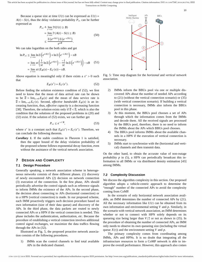
Illustrated as Fig. 5, the proposed proactive network associa-tion consists of the following procedures.
1) IMMs scan the control channels to find total availableAPs in the dedicated channel.
1
2
3
4
5
APs BBUsIntelligent
Mobile Machine
Fig. 5: Time step diagram for thehorizonal andvertical networkassociation.
2) IMMs inform the BBUs pool via one or multiple dis-covered APs about the number of needed APs accordingto (21) (without the vertical connection scenario) or (35)(with vertical connection scenario). If building a verticalconnection is necessary, IMMs also inform the BBUspool in this phase.
3) At this moment, the BBUs pool chooses a set of APsthrough which the information comes from the IMMsand decode them. All the received signals are processedby the BBUs pool, therefore, there is no need to informthe IMMs about the APs which BBUs pool chooses.
4) The BBUs pool informs IMMs about the available chan-nels in a HPN if the execution of vertical connection isnecessary.
5) IMMs start to synchronize with the (horizontal and verti-cal) channels and then transmit data.
On the other hand, to obtain the accurate value of non-outageprobability p in (5), a HPN can periodically broadcast this in-formation to all IMMs or via distributed density estimation [43]among IMMs.
7.2 Complexity Discussion
We discuss the algorithm complexity in this section. Our proposedalgorithm adopts a vehicle-centric approach to determine the“enough” number of the connected APs to avoid the complexitycoming from CoMP.
In the scenario of only horizontal network association avail-able, an IMM determines the number of connected APs by (21).All the necessary information likeU(t) can be obtained from itsown information and environmental settingV andp. Similarly, inthe scenario with vertical network association, an IMM determineswhether or not to connect with HPN solely depends on itsqueueing size being larger thanV/2 or not as shown in (35). Inthe procedure of obtaining the number of connected APs, an IMMonly needs to observe its own queueing size (including the virtualqueueX(t)) and the environment settingV andp.
The primary complexity comes from coordinating amongIMMs, APs and HPNs. It is no doubt that integrating all theinfrastructure resources to form a CoMP network is able to im-prove the overall performance. However, this approach also comes

1536-1233 (c) 2018 IEEE. Personal use is permitted, but republication/redistribution requires IEEE permission. See http://www.ieee.org/publications_standards/publications/rights/index.html for more information.
This article has been accepted for publication in a future issue of this journal, but has not been fully edited. Content may change prior to final publication. Citation information: DOI 10.1109/TMC.2018.2815702, IEEETransactions on Mobile Computing
11
20
20
20
40
40
40
60
60
60
60 80
80
80
80
100
100
100
100
120
120
120
140
140
140
160
160
160
180
180
AP density (APs/m2)
Mob
ile m
achi
ne d
ensi
ty (
MM
s/m2 )
Maximal Data Rate (packet/s) for Stable Condition
2 4 6 8 10
x 10−5
2
4
6
8
10
12
14
x 10−4
Fig. 6: Maximal data rate to guarantee the stable condition in(17)without the assistance of vertical association.
with increased complexity due to additional authorization proce-dures, pilots signals, synchronization issues and signal processing.Complexity increases with the number of APs [22]. Take thiscomplexity into consideration, a load-aware approach to controlthe size of the CoMP also attracts other research’s interests [25].Based on the IMMs’ available information, such vehicle-centricapproach does not rely on frequent control signalling and thusobtain better delay performance. To strike the balance betweenthe complexity and the performance gain from CoMP, we proposethe algorithm to satisfy the delay requirements and simultaneouslykeep the utilization number of APs be as small as possible.
8 PERFORMANCE OF NETWORK ASSOCIATION
SCHEME
8.1 Simulation Result
In the simulation, we use the parameters setting asR = 200,v = 15, J = 20, θ = 3. Considering the Doppler shift effect,the coherence time is about5ms under the velocityv = 15m/s(55km/h) with a carrier frequency2GHz. Therefore, we set theduration of time slot5ms. We set the non-outage thresholdθ = 3
to guarantee at least QPSK being reliably transmitted per symboltime. Due to obstruction effect of the buildings, we set the path-loss exponentα = 6. The total duration time of the simulation is1000s and the iteration times is 500. In the vertical associationscheme simulation, we assume that each IMM can be allocatedan independent channel from HPN thus each packet switched tovertical association can be successfully transmitted in one timeslot without interference. To avoid different processing time ofthe hardwares, the delay performance refers to the waiting timein queues. The additional delay caused by the coordination of themultiple APs and the HPN in the backhaul networks are capturedby the utilization rate.
To guarantee the stability of the queues under the scenariowithout the assistance of the vertical network association, the mostimportant thing is to ensure that the proposed scheme operatesunder the solution existing condition (i.e., Theorem 1). Fig. 6illustrates the contour plot of the maximal packet arrival ratecorresponding to the different densities of APs. The numeric valueon the line represents the maximal allowable data arrival rate. Thestability conditions can be guaranteed only if the operating point
10−2
10−1
100
101
102
10−3
10−2
10−1
100
101
102
V value
Del
ay (
s)
Packet Arrival Rate = 50 (packets/s), AP density 5× 10⁻⁵(1/m2)
Upper bound (λv = 10×10−4)
simulation (λv = 10×10−4)
Upper bound (λv = 8×10⁻⁴)
simulation (λv = 8×10⁻⁴)
Upper bound (λv = 5×10⁻⁴)
simulation (λv = 5×10⁻⁴)
Fig. 7: LargerV can be interpreted as higher cost of utilizing APs.Thus, it results in a less service rate and a longer waiting time inqueue (delay).
1 1.5 2 2.5 3 3.510
−4
10−3
10−2
10−1
100
101
Average AP Utilization
Del
ay (
s)
Average AP Utilization v.s. Delay
simulation (λv = 8×10⁻⁴)
simulation (λv = 6.5×10⁻⁴)
simulation (λv = 5×10⁻⁴)
Conventional Handover Scheme
Fig. 8: The proposed scheme can dynamically control the numberof APs and thus can achieve a better delay performance.
(density of APs and IMMs) is on the left-upper side of the line. Wecan find that the bottom right of the figure can support faster datatransmission. It makes sense that each IMM can transmit fastergiven more resource (available APs) with less competitors.
In Fig. 7, we illustrate the queue delay without the verticalassociation scheme corresponding differentV values. The time-average packet arrival rate isa = 50(packets/s). The engineeringmeaning ofV can be interpreted as the cost of utilizing an AP.With the largerV , the fewer APs are utilized and results in a slowerservice rate and longer waiting in a queue. We find that the delayperformance can be bounded by our analysis results inTheorem2. By adjustingV , we get the desired delay performance solely bythe analytical results. In Fig. 8, we compared our scheme withthe conventional handover scheme. The conventional handoverscheme refers to that an IMM connects to only one AP. To obtainthe best SIR, an IMM always connects to an AP with the shortestdistance. We find that the proposed scheme outperforms theconventional handover scheme in terms of the delay performance.Because the conventional scheme, which utilizes only one AP,
1536-1233 (c) 2018 IEEE. Personal use is permitted, but republication/redistribution requires IEEE permission. See http://www.ieee.org/publications_standards/publications/rights/index.html for more information.
This article has been accepted for publication in a future issue of this journal, but has not been fully edited. Content may change prior to final publication. Citation information: DOI 10.1109/TMC.2018.2815702, IEEETransactions on Mobile Computing
12
100
101
102
103
104
0
0.1
0.2
0.3
0.4
0.5
0.6
0.7
0.8
0.9
1
V value
Pro
babi
lity
of v
ertic
al a
ssoc
iatio
n
AP density λap
= 5× 10⁻⁵(1/m2), vehicle density λv = 5 × 10⁻⁴(1/m2)
Upper bound a = 150 (packets/s)Simulation a = 150 (packets/s)Upper bound a = 120 (packets/s)Simulation a = 120 (packets/s)Upper bound a = 90 (packets/s)Simulation a = 90 (packets/s)
V goes to∞ in (46)
Fig. 9: The packet arrival rate exceeds the maximal allowablearrival rate, building a vertical association becomes necessary evenif V goes to infinity.
100
101
102
103
104
10−3
10−2
10−1
100
101
102
V value
Del
ay (
s)
AP density λap
= 5× 10⁻⁵(1/m2), Vehicle density λv = 5 × 10⁻⁴(1/m2)
Delay Upper bound a = 150 (packets/s)
Delay Upper bound a = 120 (packets/s)
Delay Upper bound a = 90 (packets/s)
Simulation a = 150 (packets/s)
Simulation a = 120 (packets/s)
Simulation a = 90 (packets/s)
Fig. 10: If V is small, the IMMs with larger average packet arrivalrate a can slight benefit from frequent utilization of the verticalassociation.
lacking flexibility, the queue cannot be alleviated successfully.However, if we consider the proposed multiple-to-multiple net-work association, the delay performance can be improved largely.It should be noted that the proposed scheme can dynamicallyadjust the number of the connected APs. It connects more APsonly if the size of queues keep growing. Therefore, the proposedscheme also achieves AP-utilization efficiency.
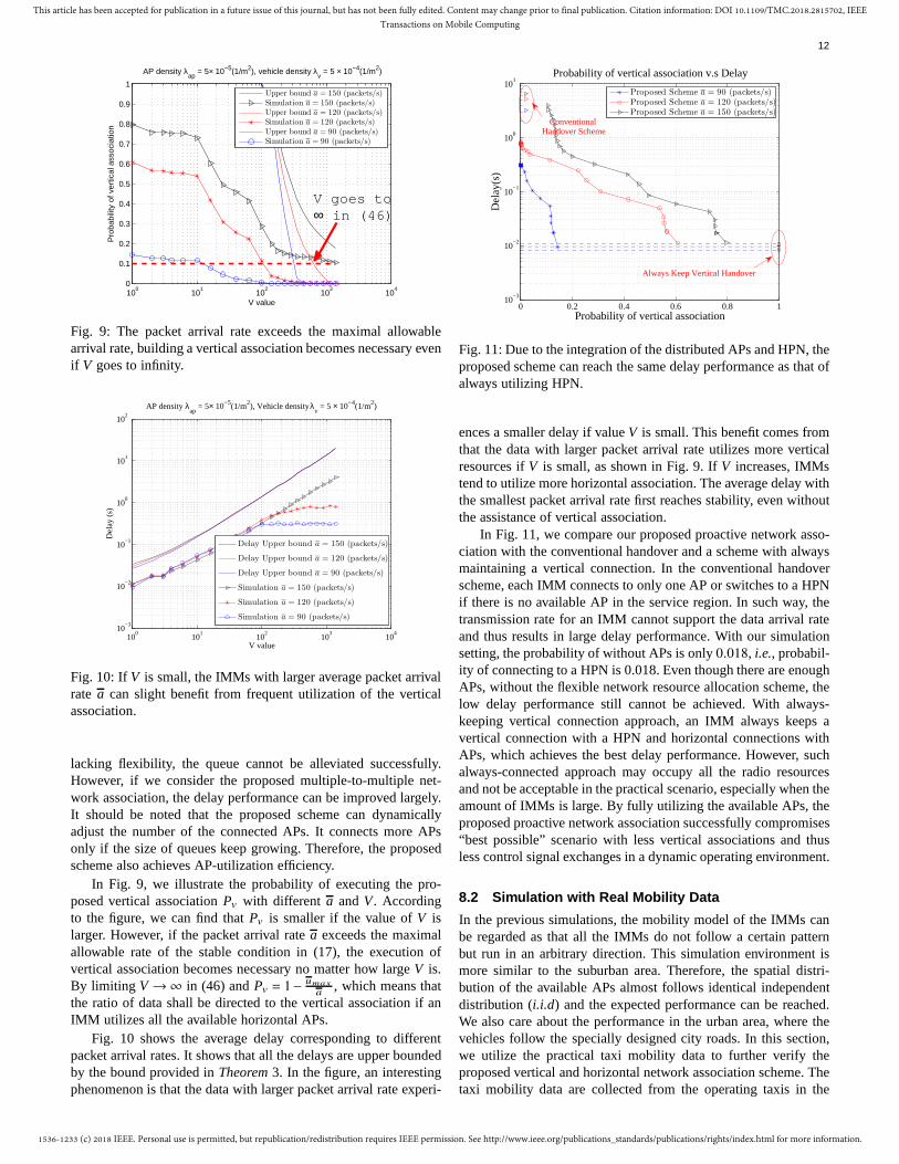
In Fig. 9, we illustrate the probability of executing the pro-posed vertical associationPv with different a and V . Accordingto the figure, we can find thatPv is smaller if the value ofV islarger. However, if the packet arrival ratea exceeds the maximalallowable rate of the stable condition in (17), the execution ofvertical association becomes necessary no matter how largeV is.By limiting V →∞ in (46) andPv = 1− umax
a, which means that
the ratio of data shall be directed to the vertical association if anIMM utilizes all the available horizontal APs.
Fig. 10 shows the average delay corresponding to differentpacket arrival rates. It shows that all the delays are upper boundedby the bound provided inTheorem 3. In the figure, an interestingphenomenon is that the data with larger packet arrival rate experi-
0 0.2 0.4 0.6 0.8 110
−3
10−2
10−1
100
101
Probability of vertical association
Del
ay(s
)
Probability of vertical association v.s Delay
Proposed Scheme a = 90 (packets/s)Proposed Scheme a = 120 (packets/s)Proposed Scheme a = 150 (packets/s)
Conventional Handover Scheme
Always Keep Vertical Handover
Fig. 11: Due to the integration of the distributed APs and HPN,theproposed scheme can reach the same delay performance as that ofalways utilizing HPN.
ences a smaller delay if valueV is small. This benefit comes fromthat the data with larger packet arrival rate utilizes more verticalresources ifV is small, as shown in Fig. 9. IfV increases, IMMstend to utilize more horizontal association. The average delay withthe smallest packet arrival rate first reaches stability, even withoutthe assistance of vertical association.
In Fig. 11, we compare our proposed proactive network asso-ciation with the conventional handover and a scheme with alwaysmaintaining a vertical connection. In the conventional handoverscheme, each IMM connects to only one AP or switches to a HPNif there is no available AP in the service region. In such way, thetransmission rate for an IMM cannot support the data arrival rateand thus results in large delay performance. With our simulationsetting, the probability of without APs is only0.018, i.e., probabil-ity of connecting to a HPN is 0.018. Even though there are enoughAPs, without the flexible network resource allocation scheme, thelow delay performance still cannot be achieved. With always-keeping vertical connection approach, an IMM always keeps avertical connection with a HPN and horizontal connections withAPs, which achieves the best delay performance. However, suchalways-connected approach may occupy all the radio resourcesand not be acceptable in the practical scenario, especially when theamount of IMMs is large. By fully utilizing the available APs, theproposed proactive network association successfully compromises“best possible” scenario with less vertical associations and thusless control signal exchanges in a dynamic operating environment.
8.2 Simulation with Real Mobility Data
In the previous simulations, the mobility model of the IMMs canbe regarded as that all the IMMs do not follow a certain patternbut run in an arbitrary direction. This simulation environment ismore similar to the suburban area. Therefore, the spatial distri-bution of the available APs almost follows identical independentdistribution (i.i.d) and the expected performance can be reached.We also care about the performance in the urban area, where thevehicles follow the specially designed city roads. In this section,we utilize the practical taxi mobility data to further verify theproposed vertical and horizontal network association scheme. Thetaxi mobility data are collected from the operating taxis in the

1536-1233 (c) 2018 IEEE. Personal use is permitted, but republication/redistribution requires IEEE permission. See http://www.ieee.org/publications_standards/publications/rights/index.html for more information.
This article has been accepted for publication in a future issue of this journal, but has not been fully edited. Content may change prior to final publication. Citation information: DOI 10.1109/TMC.2018.2815702, IEEETransactions on Mobile Computing
13
0 1000 2000 3000 4000 50000
500
1000
1500
2000
2500
m
m
Example of Taxi Mobility
GPS Location: 116.4151, 39.8725
Fig. 12: Example of taxi mobility.
101
102
103
10−2
10−1
100
V
Del
ay(s
)
Comparison Between Practical Taxi Data and Simulation Result
Practical Taxi DataSimulation Result
Fig. 13: The reason for the performance loss is that the taxi maygo into the area lack of APs sometimes.
Beijing from 2012/11/01 to 2012/12/31. We randomly choose 100taxis to simulate the queues variation with the proposed networkassociation scheme and compare them with the simulation resultsin the previous section. Fig. 12 illustrates a randomly selectedtaxi. The red line is the reported location of the taxi and theblue star points are randomly distributed APs in the networkwith distribution density5× 10−5(1/m2) and the service radiusis 200(m). The GPS location of the starting point is longitude116.4151 and latitude39.8725. The distribution density of APsλap is 5×10⁻⁵(1/m2) and the service radius of each AP is 200(m).
Fig. 13 illustrates the delay performance with data arrival rate90 (packets/s). Compared with the simulation environment, we canfind that the taxis suffer from little performance loss especially ifV is large. It is the reason that some taxis may go around anarea without enough APs. We need to know that largerV meansless utilization of vertical network association in the scenario withthe assistance of the vertical network association. In the situation,where there is no enough AP, the vertical network associationproviding ubiquitous connection service plays an important role.As shown in Fig. 14, the APs cannot support all the arrivingdata sometimes. The size of the queues may increase rapidly untilreaching the threshold of triggering vertical network association or
0 0.5 1 1.5 2 2.5 3 3.5
x 106
0
20
40
60
80
100
120
140
Time Slot (5ms)
Siz
e of
Que
ue U
(t)
Example of Variation of Queue (V = 250)
The taxi goes into the area lack of the enough APs to support
the arrival data.
Fig. 14: The size of queue may increase fast until it triggers thevertical network association.
the taxis leave this area. If we setV large, the taxi cannot utilizethe vertical network association immediately and thus resultsin worse delay performance. This phenomenon can be betterexplained with the delay violation analysis. Fig. 15 illustratesthe delay violation probability under different violation thresholdswithout the vertical network association. Because different valueof V results in different service rates of the data queues, thedelay violation probability can be upper bounded bye−sB withdifferent s. However, asV increases, this upper bound may notwork anymore, like the lineV = 250. In Fig. 15, due to the taxisgoing around in an area without enough APs. The success ofdata transmissions thus highly depends on the vertical networkassociation. For smallerV , the threshold to trigger the verticalnetwork association is smaller, and hence the size of queue dropsquickly even if the taxis are in this kind of areas. In Fig. 16,we compared with the results with the ideal movement mode.We can find that the performances are similar if the triggeringthreshold of vertical network association is small. IfV is large(V = 150,250 in Fig. 16), the simulation results are better than theone with practical taxi data. This result shows that if the movementis similar to the ideal movement, like on the highway or suburbanenvironment, the distributed APs can support the arriving dataalone. However, if the environment is similar to the urban area (asthe practical data), the vertical network association plays a moreimportant role to guarantee the delay performance. Consequently,the largerV may result in insufficient utilization of the verticalnetwork and the delay violation probability cannot be guaranteed.
9 CONCLUSION
In this paper, a proactive network association scheme that canprovide multiple-to-multiple switches are proposed. We regardthe network association as dynamic resource allocation in het-erogeneous networks, with two different types of resources:hor-izontal and vertical associations. This resource-allocation-basedapproach is quite different from conventional network associationor handover technology in cellular networks. The correspondingdynamic resource allocation problems are proposed to utilize radioresources in the most efficient way. To solve the proposed dy-namic optimization problem, we take the advantage ofLyapunovoptimization to provide IMMs with insightful decision schemes to

1536-1233 (c) 2018 IEEE. Personal use is permitted, but republication/redistribution requires IEEE permission. See http://www.ieee.org/publications_standards/publications/rights/index.html for more information.
This article has been accepted for publication in a future issue of this journal, but has not been fully edited. Content may change prior to final publication. Citation information: DOI 10.1109/TMC.2018.2815702, IEEETransactions on Mobile Computing
14
0 20 40 60 80 10010
−6
10−5
10−4
10−3
10−2
10−1
100
Violation Threshold (B)
Vio
latio
n P
roba
bilit
y
Violation Probability
V = 10
V = 50
V = 75
V = 100
V = 150
V = 250
e−0.01*B
e−0.1*B
Fig. 15: Illustration of the violation probability without the verticalnetwork association.
0 2 4 6 8 10 12 14 16 18 2010
−6
10−5
10−4
10−3
10−2
10−1
100
Violation Threshold B
Vio
latio
n P
roba
bilit
y
Practical Taxi Data versus Ideal Movement Model
V = 10V = 50V = 150V = 250V = 10 (Ideal)V = 50 (Ideal)V = 150 (Ideal)V = 250 (Ideal)
Fig. 16: Comparison of the violation probability of the idealandpractical movement data with the assistance of vertical networkassociation.
guarantee the low-latency and ultra-reliable communication withefficacious utilization of limited distributed APs and HPNs simul-taneously. The proposed proactive network association utilizes aminimal number of APs and trigger the vertical association onlyif it is necessary, which profits by less information exchangesand thus reduction of the delay in highly dynamic operation likevehicular networks.
ACKNOWLEDGEMENT
This work was supported in part by the Hong Kong, Macao andTaiwan Science and Technology Cooperation Projects under Grant(2016YFE0122900 and 2014DFT10320).
APPENDIX A
Proof: We definef (n(t)) as the objective function in (28)
f (n(t)) = 2U(t)(1−(1− p)n(t))−Vn(t),
and the optimal solution asN∗. The optimal solution should satisfytwo conditions. The first is
f (N∗)− f (N∗+1)
= 2U(t)(1−(1− p)N∗
)−V N∗
−(2U(t)(1−(1− p)N∗+1)−V (N∗
+1))
= −2U(t)(1− p)N∗
p+V ≥ 0.
We thus get
N∗ ≥ln V
2U(t)p
ln(1− p)(54)
The second condition is
f (N∗)− f (N∗ −1) = 2U(t)(1−(1− p)N∗
)−V N∗
−(2U(t)(1−(1− p)N∗−1)−V(N∗ −1))
= 2U(t)(1− p)N∗−1p−V ≥ 0.
Then we get
N∗ ≤ln V
2U(t)p
ln(1− p)+1. (55)
Combining (54) and (55), we get
ln V2U(t)p
ln(1− p)≤ N∗ ≤
ln V2U(t)p
ln(1− p)+1, (56)
(21) can thus be obtained.
APPENDIX B
For each IMM enters into the transmission region with an angleθ, the service time,i.e., the duration staying the circular region inFig. 17, can be expressed as
2Rcosθ
v
.
Because of homogeneous property, the projection of the arrivalIMMs on the vertical axis follows uniform distribution. That is,the probability of an IMM arriving with an angleθ is R cosθdθ
R=
cosθdθ. Therefore, the expected duration of an IMM staying inthe circular transmission region is
∫ π
2
0
2Rcosθ
v
Rcosθ
Rdθ =
πR2v.
To derive the expected arrival rate of the IMMs with a velocityv, we need to refer to the Fig. 17. We first calculate the “areaincreased” rate as shown in the shadowed area in Fig. 17. In thefigure, the incremental area at the angleθ is Rv cosθdt. To obtainthe shadowed area, we integrateθ from − π
2to π
2.
∫ π
2
− π
2
Rcosθvdθdt = 2Rvdt . (57)
The spatial distribution of the APs follows a PPP with densityλap but not all the APs have remaining channels for the newlyarrival IMMs. We denote the probability of an AP being availableas Pav , i.e., the probability that not allJ channels are occupiedby the IMMs. Therefore, the effective density isλapPav and theexpected arrival rate of the IMMs is2RvλapPav .

1536-1233 (c) 2018 IEEE. Personal use is permitted, but republication/redistribution requires IEEE permission. See http://www.ieee.org/publications_standards/publications/rights/index.html for more information.
This article has been accepted for publication in a future issue of this journal, but has not been fully edited. Content may change prior to final publication. Citation information: DOI 10.1109/TMC.2018.2815702, IEEETransactions on Mobile Computing
15
Incremental
Area
Fig. 17: Illustration of the expected time staying in the transmis-sion region and the expected arrival rate.
REFERENCES
[1] S. L. Poczter and L. M. Jankovic, “The google car: Driving toward abetter future?”Journal of Business Case Studies (JBCS), vol. 10, no. 1,pp. 7–14, 2013.
[2] L. Hobert, A. Festag, I. Llatser, L. Altomare, F. Visintainer, and A. Ko-vacs, “Enhancements of v2x communication in support of cooperativeautonomous driving,”IEEE Commun. Mag., vol. 53, no. 12, pp. 64–70,Dec. 2015.
[3] “Intelligent Transport Systems (ITS): Vehicular Communications; BasicSet of Applications; Definition,” ETSI Std., Tech. Rep. ETSI TR 102638, Jun. 2009.
[4] “5G automotive vision,” White Paper, 5G PPP, Oct. 2015.[5] M. Dohler, R. W. Heath, A. Lozano, C. B. Papadias, and R. A. Valen-
zuela, “Is the PHY layer dead?”IEEE Commun. Mag., vol. 49, no. 4, pp.159–165, Apr. 2011.
[6] J. Andrews, S. Buzzi, W. Choi, S. Hanly, A. Lozano, A. Soong, andJ. Zhang, “What will 5g be?”IEEE J. Sel. Areas Commun., vol. 32,no. 6, pp. 1065–1082, Jun. 2014.
[7] R. Balakrishnan and I. Akyildiz, “Local anchor schemes for seamlessand low-cost handover in coordinated small cells,”IEEE Trans. MobileComput., vol. 15, no. 5, pp. 1182–1196, May 2016.
[8] C. L. I, J. Huang, R. Duan, C. Cui, J. . Jiang, and L. Li, “Recentprogress on c-ran centralization and cloudification,”IEEE Access, vol. 2,pp. 1030–1039, 2014.
[9] H. Zhang, C. Jiang, and J. Cheng, “Cooperative interference mitigationand handover management for heterogeneous cloud small cell networks,”IEEE Wireless Commun., vol. 22, no. 3, pp. 92–99, Jun. 2015.
[10] S. Y. Lien, S. C. Hung, K. C. Chen, and Y. C. Liang, “Ultra-low-latencyubiquitous connections in heterogeneous cloud radio access networks,”IEEE Wireless Commun., vol. 22, no. 3, pp. 22–31, Jun. 2015.
[11] R. Irmer, H. Droste, P. Marsch, M. Grieger, G. Fettweis, S. Brueck, H.-P.Mayer, L. Thiele, and V. Jungnickel, “Coordinated multipoint: Concepts,performance, and field trial results,”IEEE Commun. Mag., vol. 49, no. 2,pp. 102–111, February 2011.
[12] J.-M. Moon and D.-H. Cho, “Efficient handoff algorithm for inboundmobility in hierarchical macro/femto cell networks,”IEEE Commun.Lett., vol. 13, no. 10, pp. 755–757, Oct. 2009.
[13] J. Andrews, S. Singh, Q. Ye, X. Lin, and H. Dhillon, “An overview ofload balancing in hetnets: old myths and open problems,”IEEE WirelessCommun., vol. 21, no. 2, pp. 18–25, Apr. 2014.
[14] J. Choi, W.-H. Lee, Y.-H. Kim, J.-H. Lee, and S.-C. Kim, “Throughputestimation based distributed base station selection in heterogeneousnetworks,” IEEE Trans. Wireless Commun., vol. 14, no. 11, pp. 6137–6149, Nov. 2015.
[15] X. Luo, “Delay-oriented QoS-aware user association and resource alloca-tion in heterogeneous cellular networks,”IEEE Trans. Wireless Commun.,vol. 16, no. 3, pp. 1809–1822, Mar. 2017.
[16] M. A. A. Masri and A. B. Sesay, “Mobility-aware performance evaluationof heterogeneous wireless networks with traffic offloading,”IEEE Trans.Veh. Technol., vol. PP, no. 99, pp. 1–1, 2015.
[17] F. Mehmeti and T. Spyropoulos, “Performance analysis of mobile dataoffloading in heterogeneous networks,”IEEE Trans. Mobile Comput.,vol. 16, no. 2, pp. 482–497, Feb. 2017.
[18] T. M. Ho, N. H. Tran, L. B. Le, W. Saad, S. M. A. Kazmi, and C. S.Hong, “Coordinated resource partitioning and data offloading in wirelessheterogeneous networks,”IEEE Commun. Lett., vol. 20, no. 5, pp. 974–977, May 2016.
[19] A. Apostolaras, G. Iosifidis, K. Chounos, T. Korakis, and L. Tassiulas, “Amechanism for mobile data offloading to wireless mesh networks,”IEEETrans. Wireless Commun., vol. 15, no. 9, pp. 5984–5997, Sep. 2016.
[20] S. Paris, F. Martignon, I. Filippini, and L. Chen, “An efficient auction-based mechanism for mobile data offloading,”IEEE Trans. MobileComput., vol. 14, no. 8, pp. 1573–1586, Aug. 2015.
[21] H. Pilaram, M. Kiamari, and B. H. Khalaj, “Distributed synchronizationand beamforming in uplink relay asynchronous ofdma comp networks,”IEEE Trans. Wireless Commun., vol. 14, no. 6, pp. 3471–3480, Jun. 2015.
[22] D. Lee, H. Seo, B. Clerckx, E. Hardouin, D. Mazzarese, S. Nagata,and K. Sayana, “Coordinated multipoint transmission and reception inLTE-advanced: deployment scenarios and operational challenges,”IEEECommun. Mag., vol. 50, no. 2, pp. 148–155, Feb. 2012.
[23] R. Annavajjala, “Low-complexity distributed algorithms for uplink compin heterogeneous lte networks,”IEEE J. Commun. Netw., vol. 18, no. 2,pp. 150–161, Apr. 2016.
[24] B. Dai and W. Yu, “Sparse beamforming and user-centric clustering fordownlink cloud radio access network,”IEEE Access, vol. 2, pp. 1326–1339, 2014.
[25] S. Bassoy, M. Jaber, M. A. Imran, and P. Xiao, “Load aware self-organising user-centric dynamic CoMP clustering for 5G networks,”IEEE Access, vol. 4, pp. 2895–2906, 2016.
[26] D. Liu, S. Han, C. Yang, and Q. Zhang, “Semi-dynamic user-specificclustering for downlink cloud radio access network,”IEEE Trans. Veh.Technol., vol. 65, no. 4, pp. 2063–2077, Apr. 2016.
[27] F. Guidolin, L. Badia, and M. Zorzi, “A distributed clustering algorithmfor coordinated multipoint in lte networks,”IEEE Wireless Commun.Lett., vol. 3, no. 5, pp. 517–520, Oct 2014.
[28] China Mobile Research Institute, “White paper of next generation fron-thaul interface,” Jun. 2015.
[29] W. Y. Lee and I. F. Akyildiz, “Spectrum-aware mobility management incognitive radio cellular networks,”IEEE Trans. Mobile Comput., vol. 11,no. 4, pp. 529–542, Apr. 2012.
[30] M. Haenggi, J. Andrews, F. Baccelli, O. Dousse, and M. Franceschetti,“Stochastic geometry and random graphs for the analysis and design ofwireless networks,”IEEE J. Sel. Areas Commun., vol. 27, no. 7, pp.1029–1046, Sep. 2009.
[31] J. F. C. Kingman,Poisson Processes. Oxford University Press, 1993.[32] D. P. Bertsekas and R. G. Gallager,Data Networks. Prentice Hall, 1992.[33] L. Georgiadis, M. J. Neely, and L. Tassiulas, “Resource allocation and
cross-layer control in wireless networks,”Foundations and Trends inNetworking, vol. 1, no. 1, pp. 1–144, 2006.
[34] R. S. Sutton and A. G. Barto,Reinforcement Learning: An Introduction.The MIT Press, 1998.
[35] C. W. Sung and W. S. Wong, “User speed estimation and dynamicchannel allocation in hierarchical cellular system,” inIEEE VehicularTechnology Conference (VTC), Jun. 1994, pp. 91–95 vol.1.
[36] M. Neely, “Energy optimal control for time-varying wireless networks,”IEEE Trans. Inf. Theory, vol. 52, no. 7, pp. 2915–2934, Jul. 2006.
[37] C.-S. Chang and J. A. Thomas, “Effective bandwidth in high-speeddigital networks,”IEEE J. Sel. Areas Commun., vol. 13, no. 6, pp. 1091–1100, Aug 1995.
[38] D. Wu and R. Negi, “Effective capacity: a wireless link model for supportof quality of service,”IEEE Trans. Wireless Commun., vol. 2, no. 4, pp.630–643, Jul. 2003.
[39] J. Choi, “Effective capacity of noma and a suboptimal power controlpolicy with delay qos,”IEEE Trans. Commun., vol. 65, no. 4, pp. 1849–1858, Apr. 2017.
[40] A. A. Khalek, C. Caramanis, and R. W. Heath, “Delay-constrained videotransmission: Quality-driven resource allocation and scheduling,”IEEEJ. Sel. Topics Signal Process., vol. 9, no. 1, pp. 60–75, Feb. 2015.
[41] Y. Mao, J. Zhang, S. H. Song, and K. B. Letaief, “Stochastic joint radioand computational resource management for multi-user mobile-edgecomputing systems,”IEEE Trans. Wireless Commun., vol. PP, no. 99,pp. 1–1, 2017.
[42] C.-S. Chang, K.-C. Chen, M.-Y. You, and J.-F. Chang, “Guaranteedquality-of-service wireless access to atm networks,”IEEE J. Sel. AreasCommun., vol. 15, no. 1, pp. 106–118, Jan. 1997.
[43] S.-C. Hung, S.-Y. Lien, and K.-C. Chen, “Stochastic topology cognitionin heterogeneous networks,” inIEEE Personal, Indoor and Mobile RadioCommunications (PIMRC), Sep. 2013, pp. 194–199.