Embed Size (px)
Citation preview

DEFLECTIONLecture #19
Course Name : DESIGN OF MACHINE ELEMENTSCourse Number: MET 214

Beams (non rotating members) exposed to transverse loads experience bending moments which causes the fibers of the beam experiencing tension to elongate and the fibers subjected to compression to be shortened. Such a loading condition causes the beam to curve which can be characterized by the amount of displacement the beam shifts in the transverse direction from the unloaded position. The displacement in the transverse direction is referred to as deflection.
The designs of shafts must prevent excessive deflection. Excessive deflection in intricate, high speed machinery could interfere with and/or even prevent the desired motion.
Excess deflection could contribute to vibration problems and/or limit the speed of rotation of a shaft to avoid vibrations.
Transverse loads on shafts can result from the use of pulleys, chains and sprockets, meshing gears etc. Accordingly, the deflections of a shaft under various loading configurations must be investigated to insure the shaft will be designed to avoid excessive deflections during operation.
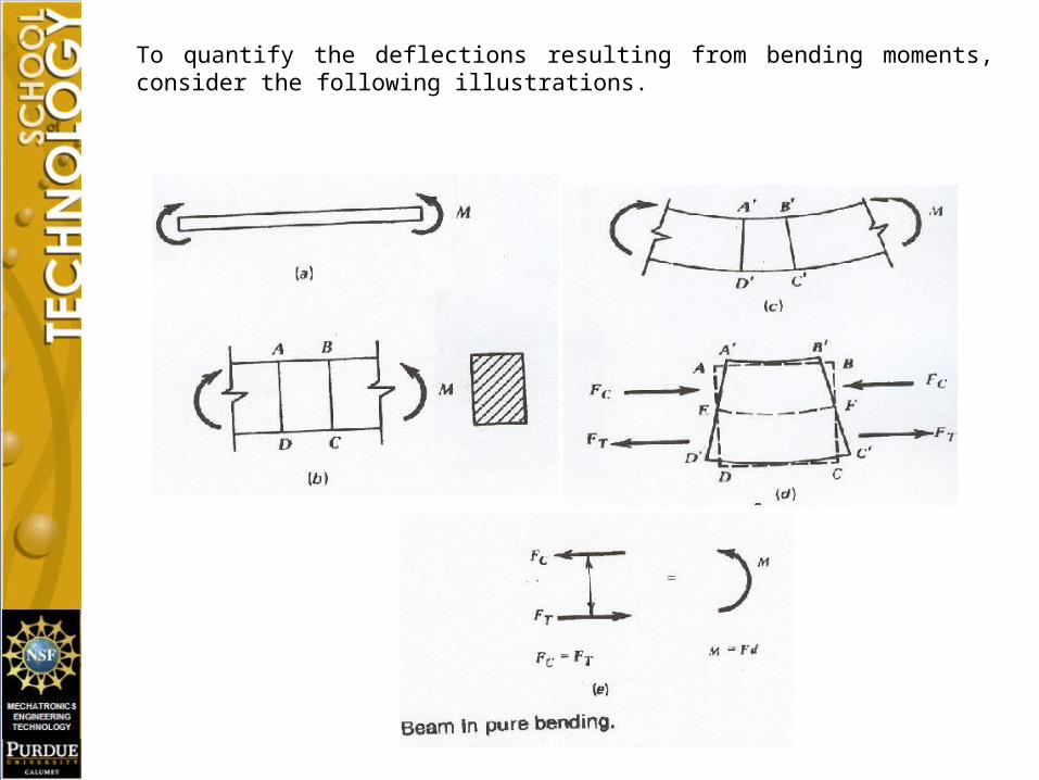
To quantify the deflections resulting from bending moments, consider the following illustrations.
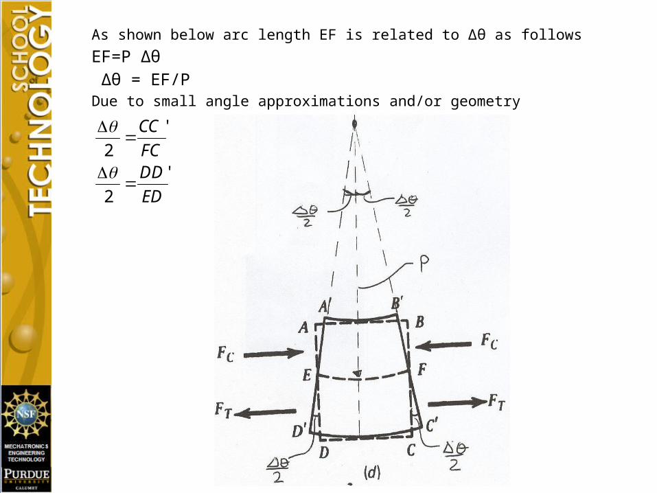
As shown below arc length EF is related to ∆θ as follows
EF=P ∆θ ∆θ = EF/PDue to small angle approximations and/or geometry
ED
DDFC
CC
'
2
'
2

Due to symmetry, FC=ED
Note where
Equating the expressions for ∆θ results in the following.
Recall that are length EF is associated with a fiber that is unchanged in length. Hence, EF is equal to the undeformed length of a fiber designated as L.
Using the definition of strain
ED
DDCC
ED
DD
FC
CC ''''
22
C
DDCC
max
max''
EDC
CEFP
P
EF
CC
P
EF
11 max
maxmax
CLP
11 max
CP
L
max1

Hook’s law is utilized to relate εmax to σmax.
Finally from previous analysis concerning bending moments, σmax can be related to bending moment.
Note: radius of curvature curvature
ECP
ECP
max
maxmax
max
1
1
EI
M
P
ECI
MC
P
I
MC
1
11
max
P
P
1
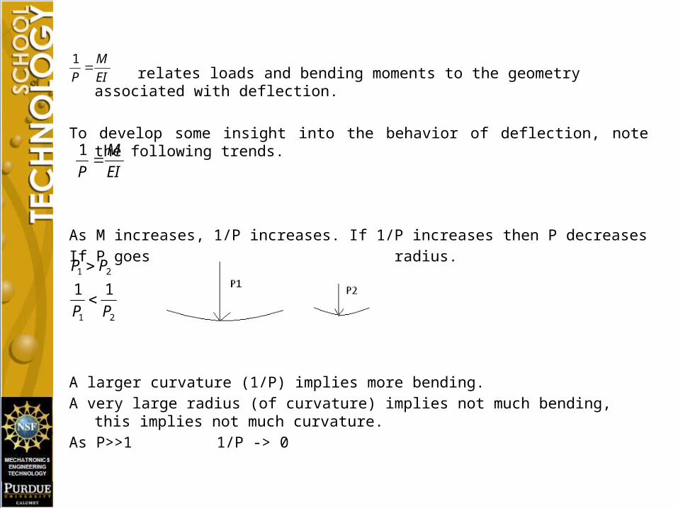
relates loads and bending moments to the geometry associated with deflection.
To develop some insight into the behavior of deflection, note the following trends.
As M increases, 1/P increases. If 1/P increases then P decreasesIf P goes down this means a tighter radius.
A larger curvature (1/P) implies more bending.A very large radius (of curvature) implies not much bending, this implies not much curvature.As P>>1 1/P -> 0
EI
M
P
1
21
21
11
PP
PP
EI
M
P
1

Ex. A steel blade for a small band saw is 0.025 in thick and runs on pulleys that are 12 in in diameter. Compute the maximum bending stress caused by bending the blade around the pulleys. Assume E=30,000,000 psi for the blade.
psi
P
C
P
CE
I
C
P
EI
I
MCP
EIM
EI
M
P
500,62
''62
025.
1
max
max

To establish a more definitive relationship between bending moments and shaft deflections due to transverse loading, the radius of curvature P must be related to the beam deflections and/or slope variations that exist when a shaft deflects under the influence of bending moments.
To develop the necessary relationships consider the diagram shown below.
P ∆θ=lIf θA and θB are relatively small
lX
dX
d
XPXP
1

Equating expressions involving 1/P enables bending moments to be related to slope and/or deflection.
Solving for dθ
Integrating both sides of the equation:
where change in slope of shaft due to bending
area under the moment diagram between any two points designated as points1 and 2
EI
M
dX
d
EI
M
P
dX
d
P
1
1
dXEI
Md
MdXEI
dXEI
Md
112
MdX

The change in slope between any two points on a shaft is equal to the area under the moment curve between the same two points multiplied by 1/EI .This relationship is illustrated below.
To relate bending moments to deflection, it is necessary to relate deflections to slope.For small angles, the following approximations are valid.
dXdYdX
dY
X
Ym
mdX
dY
1
1tan

Integrating both sides of the equation establishes a relationship for deflection
Accordingly, using relationships established in strength of material classes, the following equations relate beam loading, shear, moment, slope and deflection.
Accordingly, to investigate deflection of a shaft, shear and moment diagrams are generated and by integrating the moment curve twice, deflections can be determined for a shaft subjected to transverse loads.
dXY
dXdy
dXY
dXEI
M
VdXM
wdXV

The first technique that will be discussed for determining the deflections of a shaft is the area-moment method which can be described as follows: The deviation of a point on a beam from the tangent drawn at a second point is the moment about the first point of the area under the M/EI curve between the two points.
To apply this principle it is necessary to create a diagram from a moment diagram and divide the diagram into parts, find the area and the centroid of each part from a vertical line drawn through the point B and combine the results. An example is presented below to demonstrate how to apply the area moment method to a shaft containing steps in the diameter of the shaft.
BAAB
AB
AXt
dXEI
MXt
/
/
EI
M EI
M

Example: Given the diagram shown below, find the deflection of the shaft under the load.
Due to the symmetry of the loading, After bearing reactions have been determined, shear and moment diagrams may be drawn. Shear and moment diagrams for the shaft appear on the next slide.

In order to determine the deflection under the load using the area moment method, a diagram must be prepared from the moment diagram and the EI values existing at various locations along the shaft. Using the shaft diameters given in the example and the relationship existing between diameter and the moment of inertia I for a circular shaft, the values of EI can be determined for each section of the shaft that has a different diameter by using the equation provided below.

Assuming E = 30 X psi, the values for EI for each section of the shaft that has a different diameter may be determined.
`
After the EI values have been determined, the EI values are applied to the moment diagram to create a diagram as shown below.

The diagram may be divided into sub areas to facilitate the computation of the deviation under the load. A sub divided diagram for the example is shown below.
The values for each of the areas shown above have been calculated and are as follows:
A1 = A6 = .00296 A2 = A5 = .000632 A3= A4 = .000424

Using the area moment method, the deviation under the load may be determined from the following equation.
Values for the distances between a line through the point B and the centroids of the areas are presented below.
Using the values provided above the following value for results.
= .016631 in
The value for the deviation may be converted to deflection. The manipulations that must be performed can be determined from the diagram shown on the next slide.

The following equation may be used to determine the deviation

The values for the areas have already been determined. The values to be used in locating the centroid of each sub area from a vertical line drawn through point C are shown below.
Using the above values, the deviation may be computed: = .0560293
using the value of and the geometry identified earlier, the value of h may be computed: h = 0.5 = .0280146Using the value of h and the value of , the deflection may be computed from the following equation:
= h - = .0280146-.016631 = .01138