Embed Size (px)
Citation preview

Chapter 1
DEFINITIONS AND GENERAL EQUIREMENTS
1.1 INTRODUCTION
1.1.1 SCOPE
The definitions providing meanings of different terms and general requirements for the structural design of
buildings, structures, and components thereof are specified in this chapter. These requirements shall apply to all
buildings and structures or their components regulated by this code. All anticipated loads required for structural
design shall be determined in accordance with the provisions of Chapter 2. Design parameters required for the
structural design of foundation elements shall conform to the provisions of Chapter 3. Design of structural members
using various construction materials shall comply with the relevant provisions of Chapters 4 through 13. The FPS
equivalents of the empirical expressions used throughout Part 6 are listed in Appendix A.
This Code shall govern in all matters pertaining to design, construction, and material properties wherever this Code
is in conflict with requirements contained in other standards referenced in this Code. However, in special cases
where the design of a structure or its components cannot be covered by the provisions of this code, other relevant
internationally accepted codes referred in this code may be used.
1.1.2 DEFINITIONS
The following definitions shall provide the meaning of certain terms used in this chapter.
BASE SHEAR : Total design lateral force or shear at the base of a structure.
BASIC WIND SPEED : Three‐second gust speed at 10 metres above the mean ground level in terrain Exposure‐B
defined in Sec 2.4.8 and associated with an annual probability of occurrence of 0.02.
BEARING WALL SYSTEM : A structural system without a complete vertical load carrying space frame.
BRACED FRAME : An essentially vertical truss system of the concentric or eccentric type which is provided to resist
lateral forces.
BUILDING FRAME SYSTEM : An essentially complete space frame which provides support for loads.
CONCENTRIC BRACED FRAME (CBF) : A steel braced frame designed in conformance with Sec 10.20.13. or 10.20.14.
COLLECTOR : A member or element used to transfer lateral forces from a portion of a structure to the vertical
elements of the lateral force resisting elements.
BUILDINGS : Structures that enclose a space and are used for various occupancies.
DEAD LOAD : The load due to the weight of all permanent structural and nonstructural components of a building or
a structure, such as walls, floors, roofs and fixed service equipment.
DIAPHRAGM : A horizontal or nearly horizontal system acting to transmit lateral forces to the vertical resisting
elements. The term "diaphragm" includes horizontal bracing systems.

Part 6
2
DUAL SYSTEM : A combination of Moment Resisting Frames and Shear Walls or Braced Frames to resist lateral loads
designed in accordance with the criteria of Sec 1.3.2.
ECCENTRIC BRACED FRAME (EBF) : A steel braced frame designed in conformance with Sec 10.20.15.
HORIZONTAL BRACING SYSTEM : A horizontal truss system that serves the same function as a floor or roof
diaphragm.
INTERMEDIATE MOMENT RESISTING FRAME (IMRF) : A concrete moment resisting frame designed in accordance
with Sec 8.3.10.
LIVE LOAD : The load superimposed by the use and occupancy of a building.
MOMENT RESISTING FRAME : A frame in which members and joints are capable of resisting forces primarily by
flexure.
ORDINARY MOMENT RESISTING FRAME (OMRF) : A moment resisting frame not meeting special detailing
requirements for ductile behaviour.
PRIMARY FRAMING SYSTEM : That part of the structural system assigned to resist lateral forces.
SHEAR WALL : A wall designed to resist lateral forces parallel to the plane of the wall (sometimes referred to as a
vertical diaphragm or a structural wall).
SLENDER BUILDINGS AND STRUCTURES : Buildings and structures having a height exceeding five times the least
horizontal dimension, or having a fundamental natural frequency less than 1 Hz. For those cases where the
horizontal dimensions vary with height, the least horizontal dimension at mid height shall be used.
SOFT STOREY : Storey in which the lateral stiffness is less than 70 per cent of the stiffness of the storey above.
SPACE FRAME : A three‐dimensional structural system without bearing walls composed of members interconnected
so as to function as a complete self contained unit with or without the aid of horizontal diaphragms or floor bracing
systems.
SPECIAL MOMENT RESISTING FRAME (SMRF) : A moment resisting frame specially detailed to provide ductile
behaviour complying with the requirements of Chapter 8 or 10 for concrete or steel frames respectively.
SPECIAL STRUCTURAL SYSTEM : A structural system not listed in Table 1.3.1 and specially designed to carry the
lateral loads. See Sec 1.3.2.5.
STOREY : The space between any two floor levels including the roof of a building. Storey‐x is the storey below level
x.
STOREY SHEAR, Vx : The summation of design lateral forces above the storey under consideration.
STRENGTH : The usable capacity of an element or a member to resist the load as prescribed in these provisions.
TERRAIN : The ground surface roughness condition when considering the size and arrangement of obstructions to
the wind.
THREE‐SECOND GUST SPEED : The highest average wind speed over a 3 second duration at a height of 10 m. The
three‐second gust speed is derived using Durst's model in terms of the mean wind speed and turbulence intensity.
TOWER : A tall, slim vertical structure.
VERTICAL LOAD‐CARRYING FRAME : A space frame designed to carry all vertical gravity loads.
WEAK STOREY : Storey in which the lateral strength is less than 80 per cent of that of the storey above.
Chapter 1
3
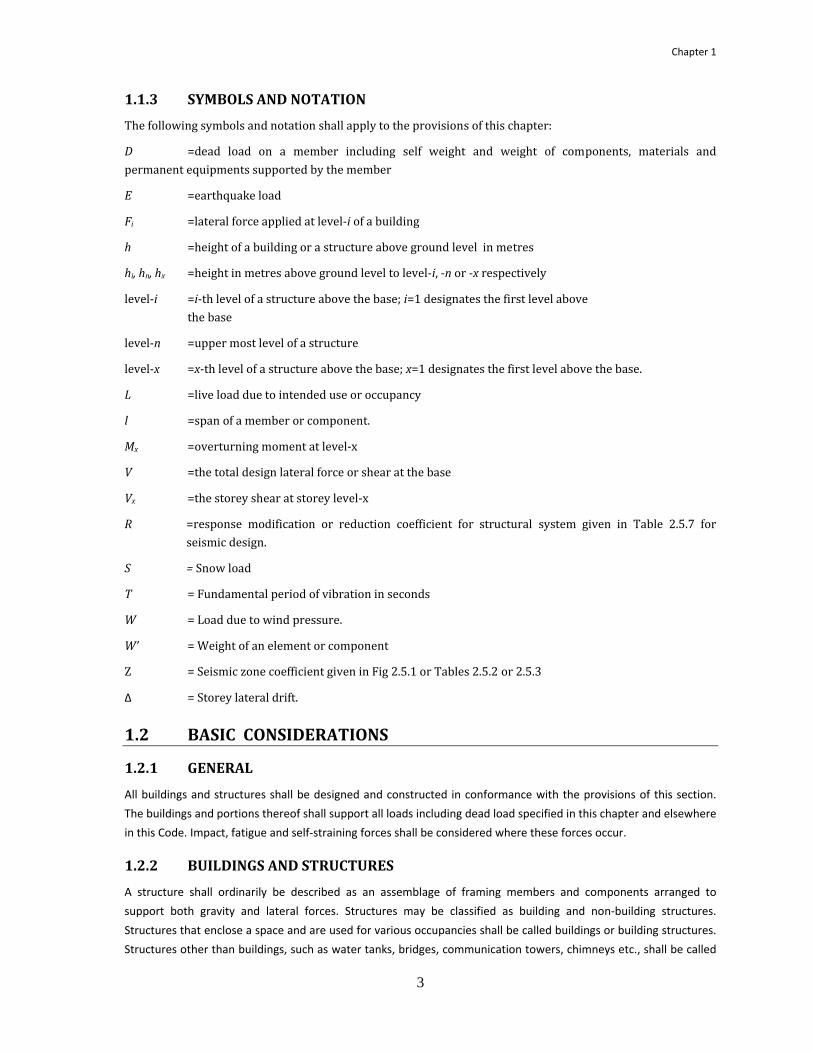
1.1.3 SYMBOLS AND NOTATION
The following symbols and notation shall apply to the provisions of this chapter:
D =dead load on a member including self weight and weight of components, materials and permanent equipments supported by the member
E =earthquake load
Fi =lateral force applied at level‐i of a building
h =height of a building or a structure above ground level in metres
hi, hn, hx =height in metres above ground level to level‐i, ‐n or ‐x respectively
level‐i =i‐th level of a structure above the base; i=1 designates the first level above the base
level‐n =upper most level of a structure
level‐x =x‐th level of a structure above the base; x=1 designates the first level above the base.
L =live load due to intended use or occupancy
l =span of a member or component.
Mx =overturning moment at level‐x
V =the total design lateral force or shear at the base
Vx =the storey shear at storey level‐x
R =response modification or reduction coefficient for structural system given in Table 2.5.7 for seismic design.
S = Snow load
T = Fundamental period of vibration in seconds
W = Load due to wind pressure.
W’ = Weight of an element or component
Z = Seismic zone coefficient given in Fig 2.5.1 or Tables 2.5.2 or 2.5.3
∆ = Storey lateral drift.
1.2 BASIC CONSIDERATIONS
1.2.1 GENERAL
All buildings and structures shall be designed and constructed in conformance with the provisions of this section.
The buildings and portions thereof shall support all loads including dead load specified in this chapter and elsewhere
in this Code. Impact, fatigue and self‐straining forces shall be considered where these forces occur.
1.2.2 BUILDINGS AND STRUCTURES
A structure shall ordinarily be described as an assemblage of framing members and components arranged to
support both gravity and lateral forces. Structures may be classified as building and non‐building structures.
Structures that enclose a space and are used for various occupancies shall be called buildings or building structures.
Structures other than buildings, such as water tanks, bridges, communication towers, chimneys etc., shall be called

Part 6
4
non‐building structures. When used in conjunction with the word building(s), the word structure(s) shall mean non‐
building structures, e.g. 'buildings and structures' or 'buildings or structures'. Otherwise the word 'structures' shall
include both buildings and non‐building structures.
1.2.3 BUILDING AND STRUCTURE OCCUPANCY CATEGORIES
Buildings and other structures shall be classified, based on the nature of occupancy, according to Table 1.2.1 for the
purposes of applying flood, surge, wind and earthquake provisions. The occupancy categories range from I to IV,
where Occupancy Category I represents buildings and other structures with a low hazard to human life in the event
of failure and Occupancy Category IV represents essential facilities. Each building or other structure shall be
assigned to the highest applicable occupancy category or categories. Assignment of the same structure to multiple
occupancy categories based on use and the type of load condition being evaluated (e.g., wind or seismic) shall be
permissible.
When buildings or other structures have multiple uses (occupancies), the relationship between the uses of various
parts of the building or other structure and the independence of the structural systems for those various parts shall
be examined. The classification for each independent structural system of a multiple‐use building or other structure
shall be that of the highest usage group in any part of the building or other structure that is dependent on that basic
structural system.
1.2.4 SAFETY
Buildings, structures and components thereof, shall be designed and constructed to support all loads, including
dead loads, without exceeding the allowable stresses or specified strengths (under applicable factored loads) for the
materials of construction in the structural members and connections.
1.2.5 SERVICEABILITY
Structural framing systems and components shall be designed with adequate stiffness to have deflections, vibration,
or any other deformations within the serviceability limit of building or structure. The deflections of structural
members shall not exceed the more restrictive of the limitations provided in Chapters 2 through 13 or that
permitted by Table 1.2.2 or the notes that follow. For wind and earthquake loading, story drift and sway shall be
limited in accordance with the provisions of Sec 1.5.6.
1.2.6 RATIONALITY
Structural systems and components thereof shall be analyzed, designed and constructed based on rational methods
which shall include, but not be limited to, the provisions of Sec 1.2.7
1.2.7 ANALYSIS
Analysis of the structural systems shall be made for determining the load effects on the resisting elements and
connections, based on well established principles of mechanics taking equilibrium, geometric compatibility and both
short and long term properties of the construction materials into account and incorporating the following:
1.2.7.1 MATHEMATICAL MODEL
A mathematical model of the physical structure shall represent the spatial distribution of stiffness and other
properties of the structure which is adequate to provide a complete load path capable of transferring all loads and
forces from their points of origin to the load‐resisting elements for obtaining various load effects. For dynamic
analysis, mathematical model shall also incorporate the appropriately distributed mass and damping properties of

Chapter 1
5
the structure adequate for the determination of the significant features of its dynamic response. All buildings and
structures shall be thus ananlyzed preferably using a three dimensional computerized model incorporating these
features of mathematical model. It is essential to use three dimensional computer model to represent a structure
having irregular plan configuration such as those listed in Tables 1.3.2 and 1.3.3 and having rigid or semirigid floor
and roof diaphragms. Requirements for two‐dimensional model and three dimensional models for earthquake
analysis are described in Sec.2.5.11 to 2.5.14. Table 1.2.1 Occupancy Category of Buildings and Other Structures for Flood, Surge, Wind and Earthquake Loads
Nature of Occupancy
OccupancyCategory
Buildings and other structures that represent a low hazard to human life in the event of failure, including, but not limited to: • Agricultural facilities • Certain temporary facilities • Minor storage facilities
I
All buildings and other structures except those listed in Occupancy Categories I, III, and IV II
Buildings and other structures that represent a substantial hazard to human life in the event of failure, including, but not limited to: • Buildings and other structures where more than 300 people congregate in one area • Buildings and other structures with daycare facilities with a capacity greater than 150 • Buildings and other structures with elementary school or secondary school facilities with a capacity greater than 250 • Buildings and other structures with a capacity greater than 500 for colleges or adult education facilities • Health care facilities with a capacity of 50 or more resident patients, but not having surgery or emergency
treatment facilities • Jails and detention facilities
Buildings and other structures, not included in Occupancy Category IV, with potential to cause a substantial economic impact and/or mass disruption of day‐to‐day civilian life in the event of failure, including, but not limited to: • Power generating stationsa • Water treatment facilities • Sewage treatment facilities • Telecommunication centers
Buildings and other structures not included in Occupancy Category IV (including, but not limited to, facilities that manufacture, process, handle, store, use, or dispose of such substances as hazardous fuels, hazardous chemicals, hazardous waste, or explosives) containing sufficient quantities of toxic or explosive substances to be dangerous to the public if released.
III
Buildings and other structures designated as essential facilities, including, but not limited to: • Hospitals and other health care facilities having surgery or emergency treatment facilities • Fire, rescue, ambulance, and police stations and emergency vehicle garages • Designated earthquake, hurricane, or other emergency shelters • Designated emergency preparedness, communication, and operation centers and other facilities required for
emergency response • Power generating stations and other public utility facilities required in an emergency • Ancillary structures (including, but not limited to, communication towers, fuel storage tanks, cooling towers,
electrical substation structures, fire water storage tanks or other structures housing or supporting water, or other fire‐suppression material or equipment) required for operation of Occupancy Category IV structures during an emergency
• Aviation control towers, air traffic control centers, and emergency aircraft hangars • Water storage facilities and pump structures required to maintain water pressure for fire suppression • Buildings and other structures having critical national defense functions
Buildings and other structures (including, but not limited to, facilities that manufacture, process, handle, store, use, or dispose of such substances as hazardous fuels, hazardous chemicals, or hazardous waste) containing highly toxic substances where the quantity of the material exceeds a threshold quantity established by the authority having jurisdiction.
IV
a Cogeneration power plants that do not supply power on the national grid shall be designated Occupancy Category II.
1.2.7.2 LOADS AND FORCES
All prescribed loads and forces to be supported by the structural systems shall be determined in accordance with
the applicable provisions of this chapter and Chapter 2. Loads shall be applied on the mathematical model specified
in Sec. 1.2.7.1 at appropriate spatial locations and along desired directions.

Part 6
6
Table 1.2.2 Deflection Limits (Except earthquake load)
In the above table l stands for span of the member under consideration; L stands for live load, W stands for wind load and D stands for dead load.
Notes:
a. For structural roofing and siding made of formed metal sheets, the total load deflection shall not exceed l/60. For secondary roof structural members supporting formed metal roofing, the live load deflection shall not exceed l/150. For secondary wall members supporting formed metal siding, the design wind load deflection shall not exceed l/90. For roofs, this exception only applies when the metal sheets have no roof covering.
b. Interior partitions not exceeding 2m in height and flexible, folding and portable partitions are not governed by the provisions of this section.
c. For cantilever members, l shall be taken as twice the length of the cantilever.
d. For wood structural members having a moisture content of less than 16 percent at time of installation and used under dry conditions, the deflection resulting from L + 0.5D is permitted to be substituted for the deflection resulting from L + D.
e. The above deflections do not ensure against ponding. Roofs that do not have sufficient slope or camber to assure adequate drainage shall be investigated for ponding. See Section 1.6.5 for rain and ponding requirements.
f. The wind load is permitted to be taken as 0.7 times the “component and cladding” loads for the purpose of determining deflection limits herein.
g. For steel structural members, the dead load shall be taken as zero.
h. For aluminum structural members or aluminum panels used in skylights and sloped glazing framing, roofs or walls of sunroom additions or patio covers, not supporting edge of glass or aluminum sandwich panels, the total load deflection shall not exceed l/60. For continuous aluminum structural members supporting edge of glass, the total load deflection shall not exceed l/175 for each glass lite or l/60 for the entire length of the member, whichever is more stringent. For aluminum sandwich panels used in roofs or walls of sunroom additions or patio covers, the total load deflection shall not exceed l/120.
1.2.7.3 SOILSTRUCTURE INTERACTION
Soil‐structure interaction effects, where required, shall be included in the analysis by appropriately including the
properly substantiated properties of soil into the mathematical model specified in Sec. 1.2.7.1 above.
1.2.8 DISTRIBUTION OF HORIZONTAL SHEAR
The total lateral force shall be distributed to the various elements of the lateral force‐resisting system in proportion
to their rigidities considering the rigidity of the horizontal bracing systems or diaphragms.

Chapter 1
7
1.2.9 HORIZONTAL TORSIONAL MOMENTS
Structural systems and components shall be designed to sustain additional forces resulting from torsion due to
eccentricity between the centre of application of the lateral forces and the centre of rigidity of the lateral force
resisting system. Forces shall not be decreased due to torsional effects. For accidental torsion effects on seismic
forces, requirements shall conform to Sec 2.5.9.6
1.2.10 STABILITY AGAINST OVERTURNING AND SLIDING
Every building or structure shall be designed to resist the overturning and sliding effects caused by the lateral forces
specified in this chapter.
1.2.11 ANCHORAGE
Anchorage of the roof to wall and columns, and of walls and columns to foundations, shall be provided to resist the
uplift and sliding forces resulting from the application of the prescribed loads. Additional requirements for masonry
or concrete walls shall be those given in Sec 1.7.3.6.
1.2.12 GENERAL STRUCTURAL INTEGRITY
Buildings and structural systems shall possess general structural integrity,that is the ability to sustain local damage
caused due to misuse or accidental overloading, with the structure as a whole remaining stable and not being
damaged to an extent disproportionate to the original local damage.
1.2.13 PROPORTIONING OF STRUCTURAL ELEMENTS
Structural elements, components and connections shall be proportioned and detailed based on the design methods
provided in the subsequent chapters for various materials of construction, such as reinforced concrete, masonry,
steel etc. to resist various load effects obtained from a rational analysis of the structural system.
1.2.14 WALLS AND FRAMING
Walls and structural framing shall be erected true and plumb in accordance with the design. Interior walls,
permanent partitions and temporary partitions exceeding 1.8 m of height shall be designed to resist all loads to
which they are subjected. If not otherwise specified elsewhere in this Code, walls shall be designed for a minimum
load of 0.25 kN/m2 applied perpendicular to the wall surfaces. The deflection of such walls under a load of 0.25
kN/m2 shall not exceed 1/240 of the span for walls with brittle finishes and 1/120 of the span for walls with flexible
finishes. However, flexible, folding or portable partitions shall not be required to meet the above load and
deflection criteria, but shall be anchored to the supporting structure.
1.2.15 ADDITIONS TO EXISTING STRUCTURES
When an existing building or structure is extended or otherwise altered, all portions thereof affected by such cause
shall be strengthened, if necessary, to comply with the safety and serviceability requirements provided in Sec 1.2.4
and 1.2.5 respectively.
1.2.16 PHASED CONSTRUCTION
When a building or structure is planned or anticipated to undergo phased construction, structural members therein
shall be investigated and designed for any additional stresses arising due to such construction.

Part 6
8
1.2.17 LOAD COMBINATIONS AND STRESS INCREASE
Every building, structure, foundation or components thereof shall be designed to sustain, within the allowable
stress or specified strength (under factored load), the most unfavourable effects resulting from various
combinations of loads specified in section 2.7. Except otherwise permitted or restricted by any other section of this
Code, maximum increase in the allowable stress shall be 33% when allowable or working stress method of design is
followed. For soil stresses due to foundation loads, load combinations and stress increase specified in Sec 2.7.4 for
allowable stress design method shall be used.
1.3 STRUCTURAL SYSTEMS
1.3.1 GENERAL
Every structure shall have one of the basic structural systems specified in Sec 1.3.2 or a combination thereof. The
structural configuration shall be as specified in Sec 1.3.4 with the limitations imposed in Sec 2.5.7.4.
1.3.2 BASIC STRUCTURAL SYSTEMS
Structural systems for buildings and other structures shall be designated as one of the types A to G listed in Table
1.3.1. Each type is again classified as shown in the table by the types of vertical elements used to resist lateral
forces. A brief description of different structural systems are presented in following sub‐sections.
Table 1.3.1: Basic Structural Systems A. BEARING WALL SYSTEMS (no frame)
1. Special reinforced concrete shear walls 2. Ordinary reinforced concrete shear walls 3. Ordinary reinforced masonry shear walls 4. Ordinary plain masonry shear walls
B. BUILDING FRAME SYSTEMS (with bracing or shear wall) 1. Steel eccentrically braced frames, moment resisting connections at columns away from links 2. Steel eccentrically braced frames, non-moment-resisting, connections at columns away from links 3. Special steel concentrically braced frames4. Ordinary steel concentrically braced frames5. Special reinforced concrete shear walls 6. Ordinary reinforced concrete shear walls 7. Ordinary reinforced masonry shear walls 8. Ordinary plain masonry shear walls
C. MOMENT RESISTING FRAME SYSTEMS (no shear wall) 1. Special steel moment frames2. Intermediate steel moment frames3. Ordinary steel moment frames4. Special reinforced concrete moment frames 5. Intermediate reinforced concrete moment frames 6. Ordinary reinforced concrete moment frames
D. DUAL SYSTEMS: SPECIAL MOMENT FRAMES CAPABLE OF RESISTING AT LEAST 25% OF PRESCRIBED SEISMIC FORCES (with bracing or shear wall)
1. Steel eccentrically braced frames2. Special steel concentrically braced frames 3. Special reinforced concrete shear walls4. Ordinary reinforced concrete shear walls
E. DUAL SYSTEMS: INTERMEDIATE MOMENT FRAMES CAPABLE OF RESISTING AT LEAST 25% OF PRESCRIBED SEISMIC FORCES (with bracing or shear wall)
1. Special steel concentrically braced frames 2. Special reinforced concrete shear walls3. Ordinary reinforced masonry shear walls 4. Ordinary reinforced concrete shear walls
F. DUAL SHEAR WALL‐FRAME SYSTEM: ORDINARY REINFORCED CONCRETE MOMENT FRAMES AND ORDINARY REINFORCED CONCRETE SHEAR WALLS G. STEEL SYSTEMS NOT SPECIFICALLY DETAILED FOR SEISMIC RESISTANCE

Chapter 1
9
1.3.2.1 BEARING WALL SYSTEM
A structural system having bearing walls or bracing systems without a complete vertical load carrying frame to
support gravity loads. Resistance to lateral loads is provided by shear walls or braced frames.
1.3.2.2 BUILDING FRAME SYSTEM
A structural system with an essentially complete space frame providing support for gravity loads. Resistance to
lateral loads is provided by shear walls or braced frames separately.
1.3.2.3 MOMENT RESISTING FRAME SYSTEM
A structural system with an essentially complete space frame providing support for gravity loads. Moment resisting
frames also provide resistance to lateral load primarily by flexural action of members, and may be classified as one
of the following types:
a) Special Moment Resisting Frames (SMRF)
b) Intermediate Moment Resisting Frames (IMRF)
c) Ordinary Moment Resisting Frames (OMRF).
The framing system, IMRF and SMRF shall have special detailing to provide ductile behaviour conforming to the
provisions of Sec 8.3 and 10.20 for concrete and steel structures respectively. OMRF need not conform to these
special ductility requirements of Chapter 8 or 10.
1.3.2.4 DUAL SYSTEM
A structural system having a combination of the following framing systems :
a) Moment resisting frames (SMRF, IMRF or steel OMRF), and
b) Shear walls or braced frames.
The two systems specified in (a) and (b) above shall be designed to resist the total lateral force in proportion to their
relative rigidities considering the interaction of the dual system at all levels. However, the moment resisting frames
shall be capable of resisting at least 25% of the applicable total seismic lateral force, even when wind or any other
lateral force governs the design.
1.3.2.5 SPECIAL STRUCTURAL SYSTEM :
A structural system not defined above nor listed in Table 1.3.1 and specially designed to carry the lateral loads, such
as tube‐in‐tube, bundled tube, etc.
1.3.2.6 NONBUILDING STRUCTURAL SYSTEM
A structural system used for purposes other than in buildings and conforming to Sec 1.5.4.8, 1.5.4.9, 2.4 and 2.5.
1.3.3 COMBINATION OF STRUCTURAL SYSTEMS
When different structural systems of Sec 1.3.2 are combined for incorporation into the same structure, design of
the combined seismic force resisting system shall conform to the provisions of Sec 2.5.7.5.
1.3.4 STRUCTURAL CONFIGURATIONS
Based on the structural configuration, each structure shall be designated as a regular or irregular structure as
defined below:
Part 6
10
1.3.4.1 REGULAR STRUCTURES
Regular structures have no significant physical discontinuities or irregularities in plan or vertical configuration or in
their lateral force resisting systems. Typical features causing irregularity are described in Sec 1.3.4.2.
1.3.4.2 IRREGULAR STRUCTURES
Irregular structures have either vertical irregularity or plan irregularity or both in their structural configurations or
lateral force resisting systems.
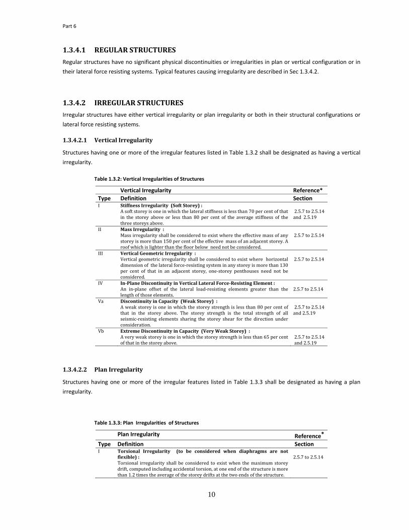
1.3.4.2.1 Vertical Irregularity
Structures having one or more of the irregular features listed in Table 1.3.2 shall be designated as having a vertical
irregularity.
Table 1.3.2: Vertical Irregularities of Structures
Vertical Irregularity Reference* Type Definition Section I Stiffness Irregularity (Soft Storey) :
A soft storey is one in which the lateral stiffness is less than 70 per cent of that in the storey above or less than 80 per cent of the average stiffness of the three storeys above.
2.5.7 to 2.5.14 and 2.5.19
II Mass Irregularity : Mass irregularity shall be considered to exist where the effective mass of any storey is more than 150 per cent of the effective mass of an adjacent storey. A roof which is lighter than the floor below need not be considered.
2.5.7 to 2.5.14
III Vertical Geometric Irregularity : Vertical geometric irregularity shall be considered to exist where horizontal dimension of the lateral force‐resisting system in any storey is more than 130 per cent of that in an adjacent storey, one‐storey penthouses need not be considered.
2.5.7 to 2.5.14
IV InPlane Discontinuity in Vertical Lateral ForceResisting Element : An in‐plane offset of the lateral load‐resisting elements greater than the length of those elements.
2.5.7 to 2.5.14
Va Discontinuity in Capacity (Weak Storey) : A weak storey is one in which the storey strength is less than 80 per cent of that in the storey above. The storey strength is the total strength of all seismic‐resisting elements sharing the storey shear for the direction under consideration.
2.5.7 to 2.5.14 and 2.5.19
Vb Extreme Discontinuity in Capacity (Very Weak Storey) : A very weak storey is one in which the storey strength is less than 65 per cent of that in the storey above.
2.5.7 to 2.5.14 and 2.5.19
1.3.4.2.2 Plan Irregularity
Structures having one or more of the irregular features listed in Table 1.3.3 shall be designated as having a plan
irregularity.
Table 1.3.3: Plan Irregularities of Structures
Plan Irregularity Reference* Type Definition Section I Torsional Irregularity (to be considered when diaphragms are not
flexible) : Torsional irregularity shall be considered to exist when the maximum storey drift, computed including accidental torsion, at one end of the structure is more than 1.2 times the average of the storey drifts at the two ends of the structure.
2.5.7 to 2.5.14

Chapter 1
11
II Reentrant Corners : Plan configurations of a structure and its lateral force‐resisting system contain reentrant corners, where both projections of the structure beyond a reentrant corner are greater than 15 per cent of the plan dimension of the structure in the given direction.
2.5.7 to 2.5.14
III Diaphragm Discontinuity : Diaphragms with abrupt discontinuities or variations in stiffness, including those having cutout or open areas greater than 50 per cent of the gross enclosed area of the diaphragm, or changes in effective diaphragm stiffness of more than 50 per cent from one storey to the next.
2.5.7 to 2.5.14
IV Outofplane Offsets : Discontinuities in a lateral force path, such as out‐of‐plane offsets of the vertical elements.
2.5.7 to 2.5.14
V Nonparallel Systems : The vertical lateral load‐resisting elements are not parallel to or symmetric about the major orthogonal axes of the lateral force‐resisting system.
2.5.7 to 2.5.14
1.4 DESIGN FOR GRAVITY LOADS
1.4.1 GENERAL
Design of buildings and components thereof for gravity loads shall conform to the requirements of this section.
Gravity loads, such as dead load and live loads applied at the floors or roof of a building shall be determined in
accordance with the provisions of Chapter 2.
1.4.2 FLOOR DESIGN
Floor slabs and decks shall be designed for the full dead and live loads as specified in Sec 2.2 and 2.3 respectively.
Floor supporting elements such as beams, joists, columns etc. shall be designed for the full dead load and the
appropriately reduced live loads set forth by the provisions of Sec 2.3.13. Design of floor elements shall also
conform to the following provisions :
a) Uniformly Distributed Loads : Where uniform floor loads are involved, consideration may be
limited to full dead load on all spans in combination with full live load on adjacent spans and
on alternate spans to determine the most unfavourable effect of stresses in the member
concerned.
b) Concentrated Loads : Provision shall be made in designing floors for a concentrated load as
set forth in Sec 2.3.5 applied at a location wherever this load acting upon an otherwise
unloaded floor would produce stresses greater than those caused by the uniform load
required therefore.
c) Partition Loads : Loads due to permanent partitions shall be treated as a dead load applied
over the floor as a uniform line load having an intensity equal to the weight per metre run of
the partitions as specified in Sec 2.2.5. Loads for light movable partitions shall be determined
in accordance with the provisions of Sec 2.3.6.
d) Design of Members : Floor members, such as slabs or decks, beams, joists etc. shall be
designed to sustain the worst effect of the dead plus live loads or any other load combinations
as specified in Sec 2.7. Where floors are used as diaphragms to transmit lateral loads between
various resisting elements, those loads shall be determined following the provisions of Sec
1.7.3.8. Detailed design of the floor elements shall be performed using the procedures
provided in Chapters 4 through 13 for various construction materials.

Part 6
12
1.4.3 ROOF DESIGN
Roofs and their supporting elements shall be designed to sustain, within their allowable stresses or specified
strength limits, all dead loads and live loads as set out by the provisions of Sec 2.2 and 2.3 respectively. Design of
roof members shall also conform to the following requirements :
a) Application of Loads : When uniformly distributed loads are considered for the design of
continuous structural members, load including full dead loads on all spans in combination with
full live loads on adjacent spans and on alternate span, shall be investigated to determine the
worst effects of loading. Concentrated roof live loads and special roof live loads, where
applicable, shall also be considered in design.
b) Unbalanced Loading : Effects due to unbalanced loads shall be considered in the design of roof
members and connections where such loading will result in more critical stresses. Trusses and
arches shall be designed to resist the stresses caused by uniform live loads on one half of the
span if such loading results in reverse stresses, or stresses greater in any portion than the
stresses produced by this unit live load when applied upon the entire span.
c) Rain Loads : Roofs, where ponding of rain water is anticipated due to blockage of roof drains,
excessive deflection or insufficient slopes, shall be designed to support such loads. Loads on
roofs due to rain shall be determined in accordance with the provisions of Sec 2.6.3. In
addition to the dead load of the roof, either the roof live load or the rain load, whichever is of
higher intensity, shall be considered in design.
1.4.4 REDUCTION OF LIVE LOADS
The design live loads specified in Sec 2.3, may be reduced to appropriate values as permitted by the provisions of
Sec 2.3.13. and Sec. 2.3.14.
1.4.5 POSTING OF LIVE LOADS
In every building, of which the floors or parts thereof have a design live load of 3.5 kN/m2 or more, and which are
used as library stack room, file room, parking garage, machine or plant room, or used for industrial or storage
purposes, the owner of the building shall ensure that the live loads for which such space has been designed, are
posted on durable metal plates as shown in Fig 1.1, securely affixed in a conspicuous place in each space to which
they relate. If such plates are lost, removed, or defaced, the owner shall be responsible to have them replaced.
1.4.6 RESTRICTIONS ON LOADING
The building owner shall ensure that the live load for which a floor or roof is or has been designed, will not be
exceeded during its use.
1.4.7 SPECIAL CONSIDERATIONS
In the absence of actual dead and live load data, the minimum values of these loads shall be those specified in Sec
2.2 and 2.3. In addition, special consideration shall be given to the following aspects of loading and due allowances
shall be made in design if occurrence of such loading is anticipated after construction of a building:
a) Increase in Dead Load: Actual thickness of the concrete slabs or other members may become
larger than the designed thickness due to movements or deflections of the formwork during
construction.

1.4.8 Structural
deflections
or that per
effects (e.g
1.5
1.5.1 Every build
wind or ea
1.5.2 Any of the
whichever
shall comp
shall also c
1.5.3 Design of
requireme
b) Fut
inst
c) Occ
tha
DEFLECT
systems and
s of structural
rmitted by Tab
g. creep, shrink
DESIGN
GENERAL
ding, structure
rthquake force
SELECTIO
e lateral loads
produces the
ply with those
conform to Sec
DESIGN F
buildings an
nts:
ure Installatio
tallations may
cupancy Chang
n that being d
TION AND C
members the
members sha
ble 1.2.2. or pro
kage or stress r
FOR LAT
L
or portions th
es, in complian
ON OF LATE
s prescribed in
most critical e
prescribed in
c 1.3.2.4.
FOR WIND L
d their comp
ons: Changes i
increase actua
ges: Increase in
esigned for.
Figure 1.1:
CAMBER
reof shall be
ll not exceed t
ovisions of Sec
relaxation) sho
TERAL LOA
hereof shall be
nce with the re
ERAL FORC
n Chapter 2, c
effect, shall gov
Sec 1.7. When
LOAD
ponents to re
13
in the numbe
al load on the f
n live loads due
Sample Live Lo
designed to h
the more restr
c 1.2.5. In calcu
ould also be co
ADS
designed to r
equirements pr
CE FOR DES
considered eit
vern the desig
n a dual struct
esist wind ind
ers, types and
floors of a build
e to changes o
ad Sign
have adequate
rictive of the li
ulating deflect
onsidered.
esist the latera
rescribed in th
SIGN
ther alone or
n. However, th
tural system is
duced forces
positions of
ding.
of occupancy in
e stiffness to l
mitations of C
ions due to gra
al load effects,
is section.
in combinatio
he structural d
used to resist
shall comply
C
partitions and
nvolving loads
limit deflectio
Chapters 2 thro
avity loads, lon
, such as those
on with other
etailing requir
t lateral loads,
y with the fo
hapter 1
d other
heavier
ns. The
ough 13
ng term
e due to
forces,
ements
, design
ollowing

Part 6
14
1.5.3.1 DIRECTION OF WIND
Structural design for wind forces shall be based on the assumption that wind may blow from any horizontal
direction.
1.5.3.2 DESIGN CONSIDERATIONS
Design wind load on the primary framing systems and components of a building or structure shall be determined on
the basis of the procedures provided in Sec 2.4 considering the basic wind speed, shape and size of the building, and
the terrain exposure condition of the site. For slender buildings and structures, dynamic response characteristics,
such as fundamental natural frequency, shall be determined for calculating the gust response coefficient. Load
effects, such as forces, moments, deflections etc. on various components of the building due to wind shall be
determined from a static analysis of the structure as specified in Sec 1.2.7.1.
1.5.3.3 SHIELDING EFFECT
Reductions in wind pressure on buildings and structures due to apparent direct shielding effects of the up wind
obstructions, such as man‐made constructions or natural terrain features, shall not be permitted.
1.5.3.4 DYNAMIC EFFECTS
Dynamic wind forces such as that from along‐wind vibrations caused by the dynamic wind‐structure interaction
effects, as set forth by the provisions of Sec 2.4.10, shall be considered in the design of regular shaped slender
buildings. For other dynamic effects such as cross‐wind or torsional responses as may be experienced by buildings
or structures having unusual geometrical shapes (i.e. vertical or plan irregularities listed in Tables 1.3.2 and 1.3.3),
response characteristics, or site locations, structural design shall be made based on the information obtained either
from other reliable references or from wind‐tunnel test specified in Sec 1.5.3.5 below, complying with the other
requirements of this section.
1.5.3.5 WIND TUNNEL TEST
Properly conducted wind‐tunnel tests shall be required for those buildings or structures having unusual geometric
shapes, response characteristics, or site locations for which cross‐wind response such as vortex shedding, galloping
etc. warrant special consideration, and for which no reliable literature for the determination of such effects is
available. This test is also recommended for those buildings or structures for which more accurate wind‐loading
information is desired than those given in this section and in Sec 2.4.
Tests for the determination of mean and fluctuating components of forces and pressures shall be considered to be
properly conducted only if the following requirements are satisfied:
a) The natural wind has been modelled to account for the variation of wind speed with height,
b) The intensity of the longitudinal components of turbulence has been taken into consideration in the
model,
c) The geometric scale of the structural model is not more than three times the geometric scale of the
longitudinal component of turbulence,
d) The response characteristics of the wind tunnel instrumentation are consistent with the measurements
to be made, and
e) The Reynolds number is taken into consideration when determining forces and pressures on the
structural elements.

Chapter 1
15
Tests for the purpose of determining the dynamic response of a structure shall be considered to be properly
conducted only if requirements (a) through (e) above are fulfilled and, in addition, the structural model is scaled
with due consideration to length, distribution of mass, stiffness and damping of the structure.
1.5.3.6 WIND LOADS DURING CONSTRUCTION
Buildings, structures and portions thereof under construction, and construction structures such as formwork,
staging etc. shall be provided with adequate temporary bracings or other lateral supports to resist the wind load on
them during the erection and construction phase.
1.5.3.7 MASONRY CONSTRUCTION IN HIGHWIND REGIONS
Design and construction of masonry structures in high‐wind regions shall conform to the requirements of relevant
sections of Chapter 7.
1.5.3.8 HEIGHT LIMITS
Unless otherwise specified elsewhere in this Code, no height limits shall be imposed, in general, on the design and
construction of buildings or structures to resist wind induced forces.
1.5.4 DESIGN FOR EARTHQUAKE FORCES
Design of structures and components thereof to resist the effects of earthquake forces shall comply with the
requirements of this section.
1.5.4.1 BASIC DESIGN CONSIDERATION
For the purpose of earthquake resistant design, each structure shall be placed in one of the seismic zones as given in
Sec 2.5.6.2 and assigned with a structure importance category as set forth in Sec 2.5.7.1. The seismic forces on
structures shall be determined considering seismic zoning, site soil characteristics, structure importance, structural
systems and configurations, height and dynamic properties of the structure as provided in Sec 2.5. The structural
system and configuration types for a building or a structure shall be determined in accordance with the provisions
of Sec 2.5.7.4. Other seismic design requirements shall be those specified in this section.
1.5.4.2 REQUIREMENTS FOR DIRECTIONAL EFFECTS
The directions of application of seismic forces used in the design shall be those which will produce the most critical
load effects. Earthquake forces act in both principal directions of the building simultaneously. Design provisions for
considering earthquake component in orthogonal directions have been provided in Sec 2.5.15.1.
1.5.4.3 STRUCTURAL SYSTEM AND CONFIGURATION REQUIREMENTS
Seismic design provisions impose the following limitations on the use of structural systems and configurations:
a) The structural system used shall satisfy requirements of the Seismic Design Category (defined in
Sec. 2.5.7.2) and height limitations given in Sec 2.5.7.4.
b) Structures assigned to Seismic Design Category D having vertical irregularity Type Vb of Table 1.3.2
shall not be permitted. Structures with such vertical irregularity may be permitted for Seismic
Design Category B or C but shall not be over two stories or 9 m in height.
c) Structures having irregular features described in Table 1.3.2 or 1.3.3 shall be designed in
compliance with the additional requirements of the sections referenced in these Tables.

Part 6
16
d) Special Structural Systems defined in Sec 1.3.2.5 may be permitted if it can be demonstrated by
analytical and test data to be equivalent, with regard to dynamic characteristics, lateral force
resistance and energy absorption, to one of the structural systems listed in Table 2.5.7, for
obtaining an equivalent R and Cd value for seismic design.
1.5.4.4 METHODS OF ANALYSIS
Earthquake forces and their effects on various structural elements shall be determined by using either a static
analysis method or a dynamic analysis method whichever is applicable based on the limitations set forth in Sec 2.5.7
through 2.5.14 and conforming to Sec 1.2.7.
1.5.4.5 MINIMUM DESIGN SEISMIC FORCE
The minimum design seismic forces shall be those determined in accordance with the Sec 2.5.7 through 2.5.14
whichever is applicable.
1.5.4.6 DISTRIBUTION OF SEISMIC FORCES
The total lateral seismic forces and moments shall be distributed among various resisting elements at any level and
along the vertical direction of a building or structure in accordance with the provisions of Sec 2.5.7 through 2.5.14
as appropriate.
1.5.4.7 VERTICAL COMPONENTS OF SEISMIC FORCES
Design provisions for considering vertical component of earthquake ground motion is given in Sec 2.5.15.2
1.5.4.8 HEIGHT LIMITS
Height limitations for different structural systems are given in Table 2.5.7 of Sec 2.5.7.4 of Part 6 of this code as a
function of seismic design category.
1.5.4.9 NONBUILDING STRUCTURES
Seismic lateral force on non‐building structures shall be determined in accordance with the provisions of Chapter 15
of ASCE 7‐ 05. However, provisions of Chapter 15 of ASCE 7‐05 may be simplified, consistent with the provisions of
Section 2.5 of Part 6 of this code. Other design requirements shall be those provided in this chapter.
1.5.5 OVERTURNING REQUIREMENTS
Every structure shall be designed to resist the overturning effects caused by wind or earthquake forces specified in
Sec 2.4 and 2.5 respectively as well other lateral forces like earth pressure, tidal surge etc. The overturning moment
Mx at any storey level‐x of a building shall be determined as :
1.5.1
where,
hi, hx, hn = Height in metres at level‐ i, ‐x or ‐n respectively.
Fi = Lateral force applied at level‐i, i=1 to n.

Chapter 1
17
At any level, the increment of overturning moment shall be distributed to the various resisting elements in the same
manner as the distribution of horizontal shear prescribed in Sec 2.5.9.5. Overturning effects on every element shall
be carried down to the foundation level.
1.5.6 DRIFT AND BUILDING SEPARATION
1.5.6.1 STOREY DRIFT LIMITATION
Storey drift is the horizontal displacement of one level of a building or structure relative to the level above or below
due to the design gravity (dead and live loads) or lateral forces (e.g. wind and earthquake loads). Except otherwise
permitted in Sec 1.3.4.2.1 calculated storey drift shall include both translational and torsional deflections and
conform to the following requirements:
1. Storey drift, ∆, for loads other than earthquake loads, shall be limited as follows:
∆ ≤ 0.005h for T < 0.7 second.
∆ ≤ 0.004h for T ≥ 0.7 second.
∆ ≤ 0.0025h for unreinforced masonry structures.
where, h = height of the building or structure.
The period T used in this calculation shall be the same as that used for determining the base shear
in Sec 2.5.9.2.
2. The drift limits set out in (1) above may be exceeded where it can be demonstrated that greater
drift can be tolerated by both structural and nonstructural elements without affecting life safety.
3. For earthquake loads, the story drift, ∆, shall be limited in accordance with the limits set forth in
Sec 2.5.16.1
1.5.6.2 SWAY LIMITATION
The overall sway (horizontal deflection) at the top level of the building or structure due to wind loading shall be
limited to 1/500 times of the total height of the building above base.
1.5.7 BUILDING SEPARATION
All components of a structure shall be designed and constructed to act as an integral unit unless they are separated
structurally by a distance sufficient to avoid contact under the most unfavourable condition of deflections due to
lateral loads. For seismic loads, design guidelines are given in Sec 2.5.16.3.
1.5.8 PDELTA EFFECTS
The resulting member forces and moments and the storey drifts induced by P‐Delta effects need not be considered
when the stability coefficient (θ) remains within 0.10. This coefficient (described in Sec 2.5.9.9) may be evaluated
for any storey as the product of the total vertical dead and live loads above the storey and the lateral drift in that
storey divided by the product of the storey shear in that storey and the height of that storey.
1.5.9 UPLIFT EFFECTS
Uplift effects caused due to lateral loads shall be considered in design. When allowable (working) stress method is
used for design, dead loads used to reduce uplift shall be multiplied by a factor of 0.85.

Part 6
18
1.6 DESIGN FOR MISCELLANEOUS LOADS
1.6.1 GENERAL
Buildings, structures and components thereof, when subject to loads other than dead, live, wind and earthquake
loads, shall be designed in accordance with the provisions of this section. Miscellaneous loads, such as those due to
temperature, rain, flood and surge etc. on buildings or structures, shall be determined in accordance with Sec 2.6.
Structural members subject to miscellaneous loads, not specified in Sec 2.6 shall be designed using well established
methods given in any reliable references, and complying with the other requirements of this Code.
1.6.2 SELFSTRAINING FORCES
Self‐straining forces such as those arising due to assumed differential settlements of foundations and from
restrained dimensional changes due to temperature, moisture, shrinkage, creep, and similar effects, shall be taken
into consideration in the design of structural members.
1.6.3 STRESS REVERSAL AND FATIGUE
Structural members and joints shall be investigated and designed against possible stress reversals caused due to
various construction loads. Where required, allowance shall be made in the design to account for the effects of
fatigue. The allowable stress may be appropriately reduced to account for such effects in the structural members.
1.6.4 FLOOD, TIDAL/STORM SURGE AND TSUNAMI
Buildings, structures and components thereof shall be designed, constructed and anchored to resist flotation,
collapse or any permanent movement due to loads including flood, tidal/Storm surge and tsunami, when applicable.
Structural members shall be designed to resist both hydrostatic and significant hydrodynamic loads and effects of
buoyancy resulting from flood or surge. Flood and surge loads on buildings and structures shall be determined in
accordance with Sec 2.6.4. Load combination including flood and surge loads shall conform to Sec 2.7. Design of
foundations to sustain these load effects shall conform to the provisions of Sec 1.8.
Stability against overturning and sliding caused due to wind and flood or surge loads simultaneously shall be
investigated, and such effects shall be resisted with a minimum factor of safety of 1.5, considering dead load only.
1.6.5 RAIN LOADS
Roofs of the buildings and structures as well as their other components which may have the capability of retaining
rainwater shall be designed for adequate gravity load induced by ponding. Roofs and such other components shall
be analysed and designed for load due to ponding caused by accidental blockage of drainage system complying with
Sec. 2.6.3.
1.6.6 OTHER LOADS
Buildings and structures and their components shall be analyzed and designed for stresses caused by the following
effects
a. Temparature Effects (Sec 2.6.5).
b. Soil and Hydrostatic Pressure (Sec 2.6.6).
c. Impacts and Collisions
d. Explosions (Sec 2.6.7).

Chapter 1
19
e. Fire
f. Vertical Forces on Air Raid Shelters (Sec 2.6.8).
g. Loads on Helicopter Landing Areas (Sec 2.6.9).
h. Erection and Construction Loads (Sec 2.6.10).
i. Moving Loads for Crane Movements
j. Creep and Shrinkage
k. Dynamic Loads due to Vibrations
l. Construction Loads
Design of buildings and structures shall include loading and stresses caused by the above effects in accordance with
the provisions set forth in Chapter 2.
1.7 DETAILED DESIGN REQUIREMENTS
1.7.1 GENERAL
All structural framing systems shall comply with the requirements of this section. Only the elements of the
designated lateral force resisting systems can be used to resist design lateral forces specified in Chapter 2. The
individual components shall be designed to resist the prescribed forces acting on them. Design of components shall
also comply with the specific requirements for the materials contained in Chapters 4 through 13. In addition, such
framing systems and components shall comply with the design requirements provided in this section.
1.7.2 STRUCTURAL FRAMING SYSTEMS
The basic structural systems are defined in Sec 1.3.2 and shown in Table 1.3.1, and each type is subdivided by the
types of framing elements used to resist the lateral forces. The structural system used shall satisfy requirements of
seismic design category and height limitations indicated in Table 2.5.7. Special framing requirements are given in
the following sections in addition to those provided in Chapters 4 through 13.
1.7.3 DETAILING REQUIREMENTS FOR COMBINATIONS OF STRUCTURAL SYSTEMS :
For components common to different structural systems, a more restrictive detailing shall be provided.
1.7.3.1 CONNECTIONS TO RESIST SEISMIC FORCES
Connections which resist prescribed seismic forces shall be designed in accordance with the seismic design
requirements provided in Chapters 4 through 13. Detailed sketches for these connections shall be given in the
structural drawings.
1.7.3.2 DEFORMATION COMPATIBILITY
All framing elements not required by design to be part of the lateral force resisting system, shall be investigated and
shown to be adequate for vertical load carrying capacity when subjected to lateral displacements resulting from the
seismic lateral forces. For designs using working stress methods, this capacity may be determined using an
allowable stress increase of 30 per cent. P‐Delta effects on such elements shall be accounted for.

Part 6
20
a. Adjoining Rigid Elements : Moment resisting frames may be enclosed or adjoined by more rigid
elements which would tend to prevent a space frame from resisting lateral forces where it can be
shown that the action or failure of the more rigid elements will not impair the vertical and lateral
load resisting ability of the space frame.
b. Exterior Elements : Exterior nonbearing, non‐shearwall panels or elements which are attached to
or enclose the exterior of a structure, shall be designed to resist the forces according to Sec. 2.5.17
of Chapter 2, if seismic forces are present, and shall accommodate movements of the structure
resulting from lateral forces or temperature changes. Such elements shall be supported by
structural members or by mechanical connections and fasteners joining them to structural
members in accordance with the following provisions:
i. Connections and panel joints shall allow for a relative movement between storeys of not less
than two times the storey drift caused by wind forces or design seismic forces, or 12 mm,
whichever is greater.
ii. Connections to permit movement in the plane of the panel for storey drift shall be either
sliding connections using slotted or oversized holes, connections which permit movement by
bending of steel, or other connections providing equivalent sliding and ductility capacity.
iii. Bodies of connections shall have sufficient ductility and rotation capability to preclude any
fracture of the anchoring elements or brittle failures at or near weldings.
iv. Bodies of the connection shall be designed for 1.33 times the seismic force determined by
Sec. 2.5.17 of Chapter 2, or equivalent.
v. All fasteners in the connection system, such as bolts, inserts, welds, dowels etc. shall be
designed for 4 times the forces determined by Sec. 2.5.17 of Chapter 2 or equivalent.
vi. Fasteners embedded in concrete shall be attached to, or hooked around reinforcing steel, or
otherwise terminated so as to transfer forces to the reinforcing steel effectively.
1.7.3.3 TIES AND CONTINUITY
All parts of a structure shall be interconnected. These connections shall be capable of transmitting the prescribed
lateral force to the lateral force resisting system. Individual members, including those not part of the seismic force–
resisting system, shall be provided with adequate strength to resist the shears, axial forces, and moments
determined in accordance with this standard. Connections shall develop the strength of the connected members
and shall be capable of transmitting the seismic force (Fp) induced by the parts being connected.
1.7.3.4 COLLECTOR ELEMENTS
Collector elements shall be provided which are capable of transferring the lateral forces originating in other
portions of the structure to the element providing the resistance to those forces.
1.7.3.5 CONCRETE FRAMES
When concrete frames are provided by design to be part of the lateral force resisting system, they shall conform to
the following provisions:
a) In Seismic Zones 3 and 4 these frames shall be designed as special moment resisting frames (SMRF).
b) In Seismic Zone 2 they shall, as a minimum, be intermediate moment resisting frames (IMRF).

Chapter 1
21
1.7.3.6 ANCHORAGE OF CONCRETE AND MASONRY STRUCTURAL WALLS
The concrete and masonry structural walls shall be anchored to supporting construction. The anchorage shall
provide a positive direct connection between the wall and floor or roof and shall be capable of resisting the
horizontal forces specified in Secs 2.4.13 and 2.5.17, or a minimum force of 4.09 kN/m of wall. Walls shall be
designed to resist bending between anchors where the anchor spacing exceeds 1.2 m. In masonry walls of hollow
units or cavity walls, anchors shall be embedded in a reinforced grouted structural element of the wall.
Deformations of the floor and roof diaphragms shall be considered in the design of the supported walls and the
anchorage forces in the diaphragms shall be determined in accordance with Sec 1.7.3.9 below.
1.7.3.7 BOUNDARY MEMBERS
Specially detailed boundary members shall be considered for shearwalls and shearwall elements whenever their
design is governed by flexure.
1.7.3.8 FLOOR AND ROOF DIAPHRAGMS
Deflection in the plane of the diaphragm shall not exceed the permissible deflection of the attached elements.
Permissible deflection shall be that deflection which will permit the attached element to maintain its structural
integrity under the individual loading and continue to support the prescribed loads. Design of diaphragms shall also
comply with the following requirements.
a) Diaphragm Forces : Diaphragms shall be designed to resist the seismic forces given in Sec 2.5 or
for similar non‐seismic lateral forces, whichever is greater.
b) Diaphragm Ties : Diaphragms supporting concrete or masonry walls shall have continuous ties, or
struts between the diaphragm chords to distribute the anchorage forces specified in Sec 1.7.3.6
above. Added chords may be provided to form sub‐diaphragms to transmit the anchorage forces to
the main cross ties.
c) Wood Diaphragms : Where wood diaphragms are used to laterally support concrete or masonry
walls, the anchorage shall conform to Sec 1.7.3.6 above. In seismic Zones 2, 3 and 4 the following
requirements shall also apply:
i. Anchorage shall not be accomplished by use of toe nails or nails subject to withdrawal,
nor shall wood ledgers or framing be used in cross‐grain bending or cross‐grain tension.
ii. The continuous ties required by paragraph (b) above, shall be in addition to the
diaphragm sheathing.
d) Structures having irregularities
i) For structures assigned to Seismic Design Category D and having a plan irregularity of Type
I, II, III, or IV in Table 1.3.3 or a vertical structural irregularity of Type IV in Table 1.3.2, the
design forces determined from Section 2.5.9 shall be increased 25 percent for connections
of diaphragms to vertical elements and to collectors and for connections of collectors to
the vertical elements. Collectors and their connections also shall be designed for these
increased forces unless they are designed for the load combinations with overstrength
factor.
ii) For structures having a plan irregularity of Type II in Table 1.3.3, diaphragm chords and
collectors shall be designed considering independent movement of any projecting wings of

Part 6
22
the structure. Each of these diaphragm elements shall be designed for the more severe of
the following cases:
1. Motion of the projecting wings in the same direction.
2. Motion of the projecting wings in opposing directions.
Exception:
This requirement may be deemed to be satisfied if the procedures of Sec 2.5.10 when seismic forces are present, in
conjunction with a three dimensional model, have been used to determine the lateral seismic forces for design.
1.7.3.9 FRAMING BELOW THE BASE
When structural framings continue below the base, the following requirements shall be satisfied.
a. Framing between the Base and the Foundation: The strength and stiffness of the framing between
the base and the foundation shall not be less than that of the superstructure . The special detailing
requirements of Sec 8.3 or 10.20, as appropriate for reinforced concrete or steel, shall apply to
columns supporting discontinuous lateral force resisting elements and to SMRF, IMRF, and EBF
system elements below the base which are required to transmit the forces resulting from lateral
loads to the foundation.
b. Foundations: The foundation shall be capable of transmitting the design base shear and the
overturning forces from the superstructure into the supporting soil, but the short term dynamic
nature of the loads may be taken into account in establishing the soil properties. Sec 1.8 below
prescribes the additional requirements for specific types of foundation construction.
1.8 FOUNDATION DESIGN REQUIREMENTS
1.8.1 GENERAL
The design and construction of foundation, foundation components and connection between the foundation and
superstructure shall conform to the requirements of this section and applicable provisions of Chapter 3 and other
portions of this Code .
1.8.2 SOIL CAPACITIES
The bearing capacity of the soil, or the capacity of the soil‐foundation system including footing, pile, pier or caisson
and the soil, shall be sufficient to support the structure with all prescribed loads, considering the settlement of the
structure. For piles, this refers to pile capacity as determined by pile‐soil friction and bearing which may be
determined in accordance with the provisions of Chapter 3. For the load combination including earthquake, the soil
capacity shall be sufficient to resist loads at acceptable strains considering both the short time loading and the
dynamic properties of the soil. The stress and settlement of soil under applied loads shall be determined based on
established methods of Soil Mechanics.
1.8.3 SUPERSTRUCTURETOFOUNDATION CONNECTION
The connection of superstructure elements to the foundation shall be adequate to transmit to the foundation the
forces for which the elements are required to be designed.
Chapter 1
23
1.8.4 FOUNDATIONSOIL INTERFACE
For regular buildings the base overturning moments for the entire structure or for any one of its lateral force‐
resisting elements, shall not exceed two‐thirds of the dead load resisting moment. The weight of the earth
superimposed over footings may be used to calculate the dead load resisting moment.
1.8.5 SPECIAL REQUIREMENTS FOR FOOTINGS, PILES AND CAISSONS IN SEISMIC ZONES 2, 3 AND 4
1.8.5.1 PILES AND CAISSONS
Piles and caissons shall be designed for flexure whenever the top of such members is anticipated to be laterally
displaced by earthquake motions. The criteria and detailing requirements of Sec 8.3 for concrete and Sec 10.20 for
steel shall apply for a length of such members equal to 120 per cent of the flexural length.
1.8.5.2 FOOTING INTERCONNECTION
a. Footings and pile caps shall be completely interconnected by strut ties or other equivalent means
to restrain their lateral movements in any orthogonal direction.
b. The strut ties or other equivalent means as specified in (a) above, shall be capable of resisting in
tension or compression a force not less than 10% of the larger footing or column load unless it can
be demonstrated that equivalent restraint can be provided by frictional and passive soil resistance
or by other established means.
1.8.6 RETAINING WALL DESIGN
Retaining walls shall be designed to resist the lateral pressure of the retained material, under drained or undrained
conditions and including surcharge, in accordance with established engineering practice. For such walls, the
minimum factor of safety against base overturning and sliding due to applied earth pressure shall be 1.5.
1.9 DESIGN AND CONSTRUCTION REVIEW Every building or structure designed shall have its design documents prepared in accordance with the provisions of
Sec 1.9.1. The minimum requirements for design review and construction observation shall be those set forth under
Sec 1.9.2 and 1.9.3 respectively.
1.9.1 DESIGN DOCUMENT
The design documents shall be prepared and signed by the engineer responsible for the structural design of any
building or structure intended for construction. The design documents shall include a design report, material
specifications and a set of structural drawings, which shall be prepared in compliance with Sec 1.9.2 and 1.9.3 below
for submittal to the concerned authority. For the purpose of this provision, the concerned authority shall be either
persons from the government approval agency for the construction, or the owner of the building or the structure, or
one of his representatives.
1.9.2 DESIGN REPORT
The design report shall contain the description of the structural design with basic design information as provided
below, so that any other structural design engineer will be able to independently verify the design parameters and
the member sizes using these basic information. The design report shall include, but not be limited to, the following
:

Part 6
24
a) Name and governing edition of this Code and other referenced standards, and the specific
portions, stating chapter, section, clause etc. of these Code and standards including any
specialist report used for the structural design.
b) Methods used for the calculation of all applied loads along with basic load coefficients and
other basic information including any assumption or judgment made under special
circumstances.
c) A drawing of the complete mathematical model prepared in accordance with Sec 1.2.7.1 to
represent the structure and showing on it the values, locations and directions of all applied
loads, and location of the lateral load resisting systems such as shear walls, braced frames etc.
d) Methods of structural analysis, and results of the analysis such as shear, moment, axial force
etc., used for proportioning various structural members and joints including foundation
members.
e) Methods of structural design including types and strength of the materials of construction
used for proportioning the structural members.
f) Reference of the soil report or any other documents used in the design of the structure,
foundation or components thereof.
g) Statement supporting the validity of the above design documents with date and signature of
the engineer responsible for the structural design.
h) When computer programs are used, to any extent, to aid in the analysis or design of the
structure, the following items, in addition to items (a) through (g) above, shall be required to
be included in the design report:
i. A sketch of the mathematical model used to represent the structure in the computer
generated analysis.
ii. The computer output containing the date of processing, program identification,
identification of structures being analysed, all input data, units and final results. The
computer input data shall be clearly distinguished from those computed in the
program.
iii. A program description containing the information necessary to verify the input data
and interpret the results to determine the nature and extent of the analysis and to
check whether the computations comply with the provisions of this Code.
iv. The first sheet of each computer run shall be signed by the engineer responsible for the
structural design.
1.9.3 STRUCTURAL DRAWINGS AND MATERIAL SPECIFICATIONS
The structural drawings shall include, but not be limited to, the following :
a) The first sheet shall contain : (1) identification of the project to which the building or the structure,
or portion thereof belongs, (2) reference to the design report specified in Sec 1.9.2 above, (3) date
of completion of design, and (4) identification and signature with date of the engineer responsible
for the structural design.

Chapter 1
25
b) The second sheet shall contain detail material specifications showing : (1) Specified compressive
strength of concrete at stated ages or stages of construction for which each part of structure is
designed (2) Specified strength or grade of reinforcement (3) Specified strength of prestressing
tendons or wires (4) Specified strength or grade of steel (5) Specified strengths for bolts, welds etc.
(6) Specified strength of masonry, timber, bamboo, ferrocement (7) Minimum concrete
compressive strength at time of post‐tensioning (8) Stressing sequence for post‐tensioning tendons
(9) General notes indicating clear cover, development lengths of reinforcements, or any other
design parameter relevant to the member or connection details provided in drawings to be
followed, as applicable, and (10) identification and signature with date of the engineer responsible
for the structural design.
c) Drawing sheets, other than the first two, shall include structural details of the elements of the
structure clearly showing all sizes, cross‐sections and relative locations, connections,
reinforcements, laps, stiffeners, welding types, lengths and locations etc. whichever is applicable
for a particular construction. Floor levels, column centres and offset etc., shall be dimensioned.
Camber of trusses and beams, if required, shall be shown on drawings. For bolt connected
members, connection types such as slip, critical, tension or bearing type, shall be indicated on the
drawing.
d) Drawings shall be prepared to a scale large enough to show the information clearly and the scales
shall be marked on the drawing sheets. If any variation from the design specifications provided in
sheet two occurs, the drawing sheet shall be provided additionally with the design specifications
including material types and strength, clear cover and development lengths of reinforcements, or
any other design parameter relevant to the member or connection details provided in that drawing
sheet. Each drawing sheet shall also contain the signature with date of the engineer responsible for
the structural design.
1.9.4 DESIGN REVIEW
The design documents specified in Sec 1.9.1 shall be available for review when required by the concerned authority.
Review shall be accomplished by an independent structural engineer qualified for this task and appointed by the
concerned authority. Design review shall be performed through independent calculations, based on the information
provided in the design documents prepared and signed by the original structural design engineer, to verify the
design parameters including applied loads, methods of analysis and design, and final design dimensions and other
details of the structural elements. The reviewing engineer shall also check the sufficiency and appropriateness of
the supplied structural drawings for construction.
1.9.5 CONSTRUCTION OBSERVATION
Construction observation shall be performed by a responsible person who will be a competent professional
appointed by the owner of the building or the structure. Construction observation shall include, but not be limited
to, the following :
a. Specification of an appropriate testing and inspection schedule prepared and signed with date by
the responsible person;
b. Review of testing and inspection reports; and
c. Regular site visit to verify the general compliance of the construction work with the structural
drawings and specifications provided in Sec 1.9.3 above.