Embed Size (px)
Citation preview
8/8/2019 Definition of Power
http://slidepdf.com/reader/full/definition-of-power 1/10
Definition of Power
Before we turn to investigating range and endurance for propeller airplanes we must define power.
We must do this because for a propeller driven airplane fuel flow is proportional to power. We willreturn to discuss fuel flow and its relationship to power on the next page. For now we should
examine what power is.
Power (P) measures the amount of work (w) the engine does in a unit of time (t.) Mathematicallywe say that:
P = w/t
Work measures the force that is applied over a given distance (d.) Mathematically we say that:
w = F x d
F x d may be familiar to you, it is simply torque. So to measure the power output of an engine allwe need to measure is:
Power output of engine = (F x d) / t
A Dynamometer
8/8/2019 Definition of Power
http://slidepdf.com/reader/full/definition-of-power 2/10
A dynamometer is a device that measures the power output of an engine. In the past the methodof measurement was to have a "brake like" device clamp onto the output shaft and measure thetorque by equating torque to the amount of braking force required to stop the engine. Moderndynamometers are much more sophisticated but the term Brake Horsepower (BHP) has survived.
A Dynamometer measures BHP - i.e. the output power of an engine. It works by measuring torque
and rpm (Note that rpm is a unit of time/(2 x pi).) These are the only two items needed.Mathematically:
BHP = torque x rpm x (unit correction factor)
In the metric system torque is measured in units of Newton x meter. RPM is by definition
revolutions per minute. Power is in units of Watts, which requires the time unit be seconds ratherthan minutes so you would need a correction factor of (2 x pi)/60.
In the engineering unit system torque is measured in units of lb x ft. RPM is measured inrevolutions per minute. Power is in units of Horse Power. One horsepower is defined as 33,000 lb x
ft / min. The appropriate unit correction factor is (2 x pi)/33,000, or 5255.
Shaft Horsepower (SHP)
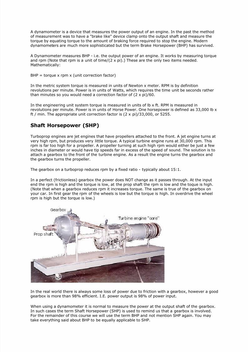
Turboprop engines are jet engines that have propellers attached to the front. A jet engine turns at
very high rpm, but produces very little torque. A typical turbine engine runs at 30,000 rpm. Thisrpm is far too high for a propeller. A propeller turning at such high rpm would either be just a few
inches in diameter or would have tip speeds far in excess of the speed of sound. The solution is toattach a gearbox to the front of the turbine engine. As a result the engine turns the gearbox and
the gearbox turns the propeller.
The gearbox on a turboprop reduces rpm by a fixed ratio - typically about 15:1.
In a perfect (frictionless) gearbox the power does NOT change as it passes through. At the input
end the rpm is high and the torque is low, at the prop shaft the rpm is low and the toque is high.(Note that when a gearbox reduces rpm it increases torque. The same is true of the gearbox onyour car. In first gear the rpm of the wheels is low but the torque is high. In overdrive the wheelrpm is high but the torque is low.)
In the real world there is always some loss of power due to friction with a gearbox, however a goodgearbox is more than 98% efficient. I.E. power output is 98% of power input.
When using a dynamometer it is normal to measure the power at the output shaft of the gearbox.In such cases the term Shaft Horsepower (SHP) is used to remind us that a gearbox is involved.For the remainder of this course we will use the term BHP and not mention SHP again. You maytake everything said about BHP to be equally applicable to SHP.
8/8/2019 Definition of Power
http://slidepdf.com/reader/full/definition-of-power 3/10
Consult the POH for BHP
Every airplane has a pilot operating handbook (POH.) In the POH you will find the rated BHP of theengine(s.)
The term "normally aspirated" means that the air entering the intake of the engine is at
atmospheric pressure. On a normally aspirated piston engine the full BHP is only available at sealevel. As the airplane climbs the power output of the engine decreases, roughly in proportion to airpressure. Thus at 18,000 feet the engine produces only half as much BHP as at sea level.
Many piston engines used in airplanes have turbo-chargers. A turbo-charger is a device thatpressurizes the air entering the engine intake. This "fools" the engine into thinking it is still at sealevel. As a result a turbo-charged engine can produce its full rated BHP up to some altitude atwhich the turbo charger reaches its limit. Above that altitude the engine starts to lose power again.
Turboprop engines are normally aspirated. The preceding is a crucial point to realize.
All turboprop engines lose power as altitude is gained. This situation is often unacceptable to theaircraft designer as it means that full power is not available for takeoff except for those fewairports that are at sea level. The solution is to use a "de-rated engine."
De-rated Engines
If you consult the POH for a turboprop airplane it will tell you the maximum BHP (SHP) of theengine. Along with this maximum BHP will be maximum torque and rpm values.( Turbopropengines normally have torque meters.) The POH will usually give a clue that the engine is de-ratedby either saying so directly or stating that full BHP is available up to some altitude, for example6000 feet. How is that possible given that the engine is normally aspirated?
The answer is that the engine can actually produce significantly more power than the rated BHP atsea level. The POH restrictions on torque and rpm limit the pilot to setting just the maximumspecified BHP. But at sea level you will find that you are not at full throttle when you reach
maximum torque and rpm. The engine actually has a "power reserve." NOTE that the same is trueof some turbo-charged piston engines.
Should you use the reserve power? Only in an emergency. The reason is that the higher outputstresses the engine. The engine runs hotter and faster and the gearbox is twisted with more torquethan it is designed for. If you run a higher than approved BHP for more than a few minutes you willdestroy the engine.
Emergency Power
Many POHs specify an emergency power option. Even if the POH doesn't, if your life is on the linepush the throttle to full and use all the available power. Just be aware that your engine that would
run quite safely at rated power for hundreds even thousands of hours, will be destroyed in a matterof minutes if you do this. Your life is worth more, but being a few minutes behind schedule isn't. Souse emergency power ONLY in an emergency.
8/8/2019 Definition of Power
http://slidepdf.com/reader/full/definition-of-power 4/10
Power Available (Pa)
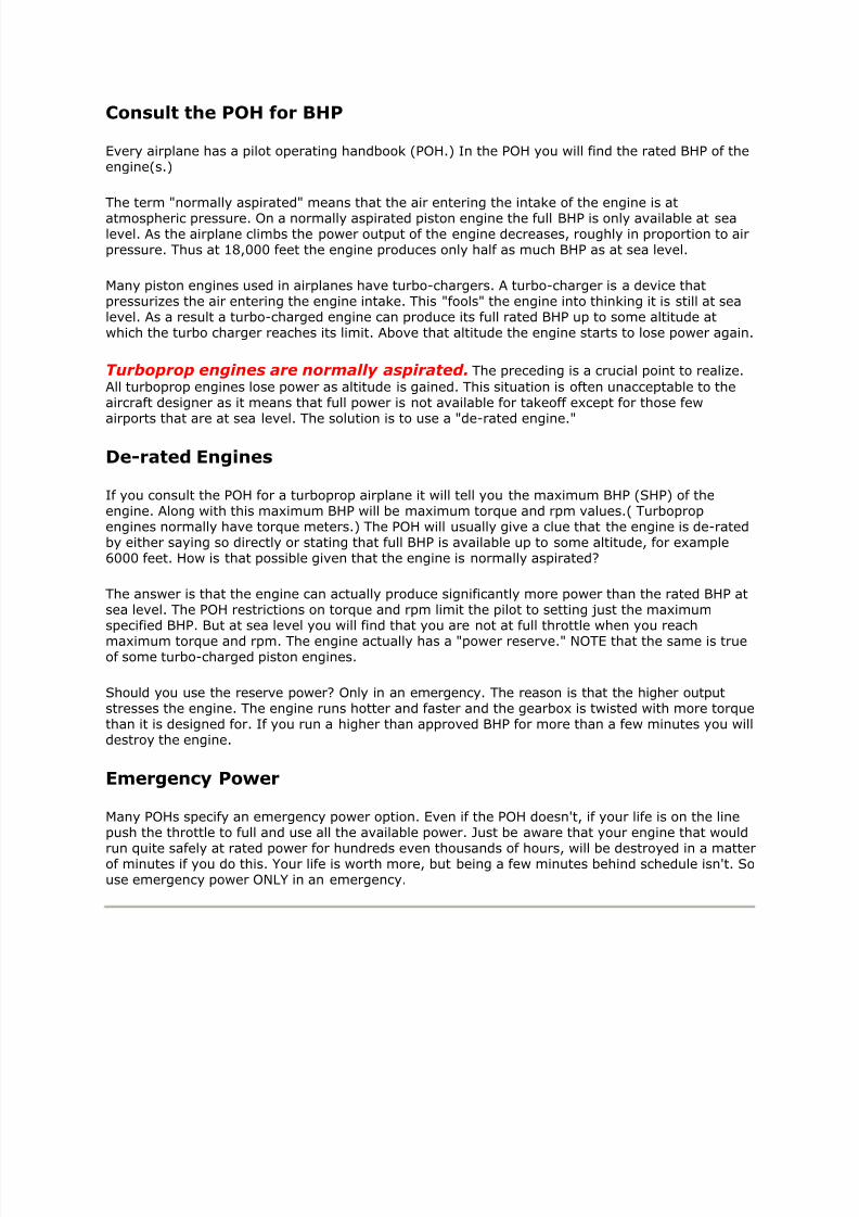
So far we have been concentrating on BHP. But the BHP is usedto turn a propeller, so it is really the power that the propellermanages to put into the air that actually moves the airplane.Imagine the engine roaring away with no propeller attached. TheBHP might be impressive, but we wouldn't be going anywhere.The effective power would be zero.
We call the power that is actually available - i.e. delivered by thepropeller Pa. This sometimes is also called the thrust horsepower(THP.) In mathematical terms:
Pa = x BHP [ is propeller efficiency. is always less than
1.0]
Propeller Efficiency
Propeller efficiency measures the percentage of BHP that is turned into useable power by thepropeller.
Mathematically: = Pa / BHP.
must be evaluated by experimental measurement or complex computer analysis. However the
factors that determine it are quite obvious. They are the same factors that determine the L/D ratioof an airplane. If you think about it the drag on a propeller is the force that engine torque must
overcome and "Lift" from a propeller is actually thrust. You should recall that we learned in thedrag chapter that L/D ratio depends on three factors; angle of attack, CDP, and Aspect ratio. The
same is true of a propeller. We will look at AOA in a moment. CDp is measure of how streamlinethe propeller is and is really not a concern because unless some propeller manufacturer loses his
mind all propellers are very streamlined. We also see that AR is important. So it is clear that alarge diameter propeller with long thin blades is more efficient than one with short stubby blades.
Most propellers meet that criteria, now it is clear why.
The determining factor for propeller efficiency then seems to be angle of attack (AOA.) We will nowexplore that in detail.
The simulation to the left demonstrates how a propeller produces lift. It also shows the relationshipbetween rpm, TAS and propeller angle of attack.
To use the simulation you change rpm using the throttle lever at the lower left corner. Just dragthe throttle with your mouse. You change airspeed using the Q-key and Z-key.
The green vector represents rpm - or more precisely the velocity of the propeller due to rpm.
The red vector represents true airspeed (TAS.)
The blue vector presents the relative wind, which is by definition opposite to the direction thepropeller travels. NOTE that the direction the propeller blade travels is the sum of the velocity due
to rpm and the TAS of the whole airplane.
The side view shows a section of the propeller blade at one specific point along the span of the
propeller. The front view shows a blue circle that you can imagine represents the distance alongthe span of the propeller section represented by the side view.
8/8/2019 Definition of Power
http://slidepdf.com/reader/full/definition-of-power 5/10
The angle of attack of the propeller blade is the angle between the chord and the relative wind(blue) vector.
Experiment with the simulation to convince yourself that as rpm increases so too does angle of attack.
Also convince yourself that as TAS increases angle of attack decreases.
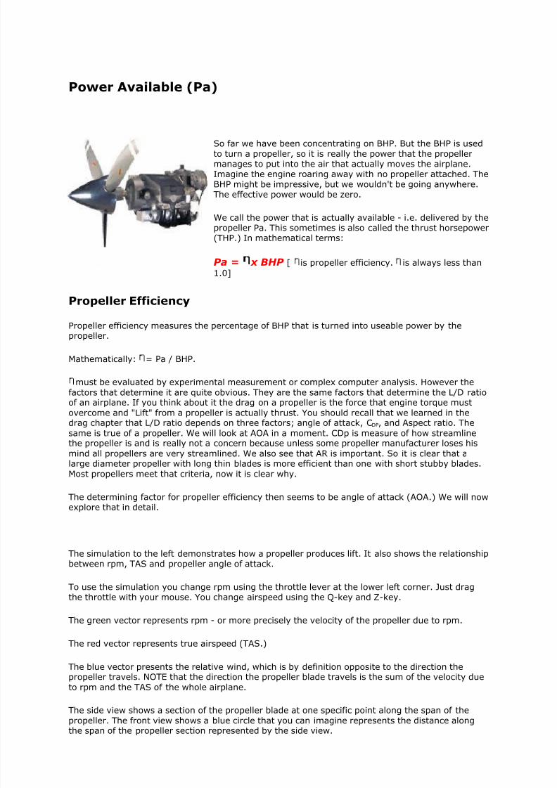
If we took the section at a different distance from the crankshaft the velocity of the propeller bladedue to rpm would be different. Velocity due to rpm is given by the formula rpm x pi x d (d is thedistance from the hub.) Close to the crankshaft velocity would be low, and further out it would begreater. This affects the angle of attack of the propeller blade. This explains why a propeller bladeis "twisted" as shown in the photograph to the left. The root of the blade must have a larger bladeangle than the tip in order that all points along the span of the blade strike the relative airflow atthe same angle of attack.
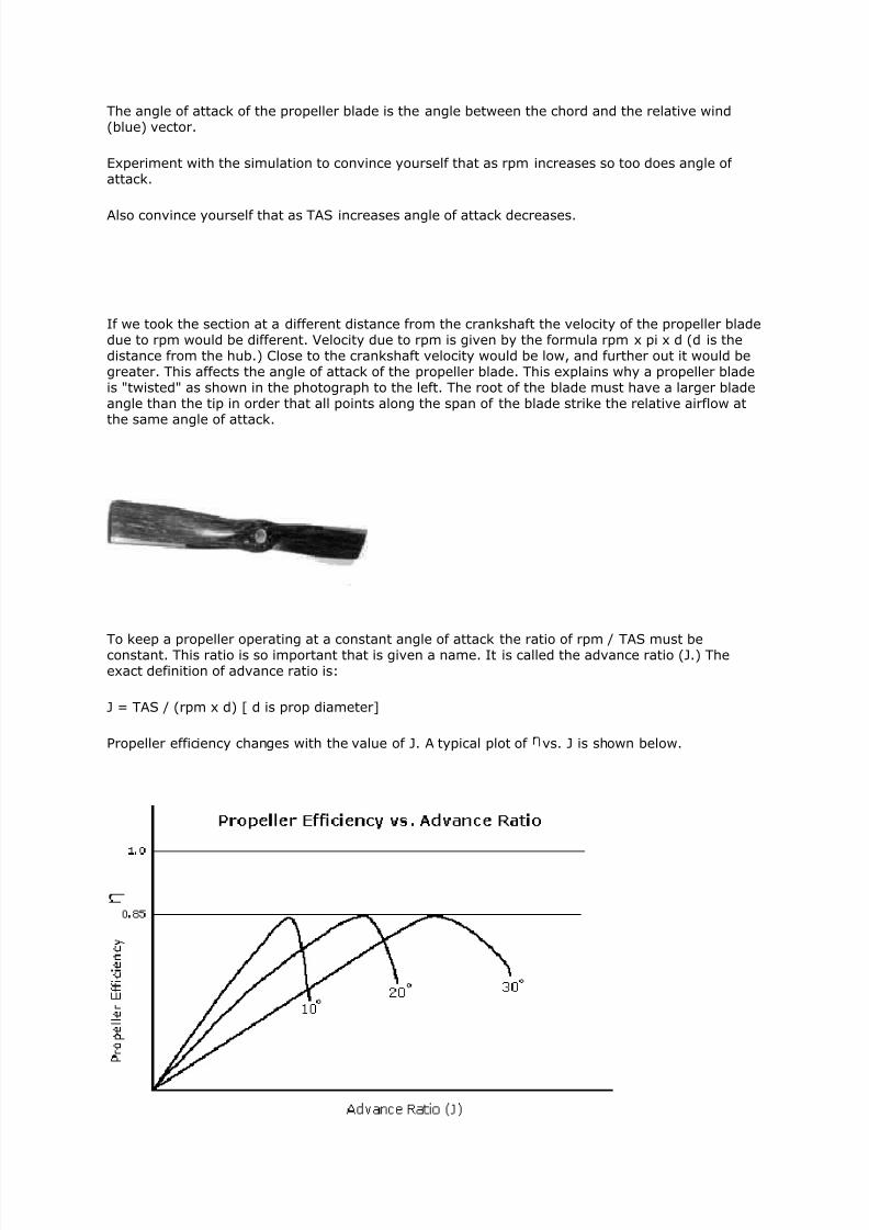
To keep a propeller operating at a constant angle of attack the ratio of rpm / TAS must beconstant. This ratio is so important that is given a name. It is called the advance ratio (J.) Theexact definition of advance ratio is:
J = TAS / (rpm x d) [ d is prop diameter]
Propeller efficiency changes with the value of J. A typical plot of vs. J is shown below.
8/8/2019 Definition of Power
http://slidepdf.com/reader/full/definition-of-power 6/10
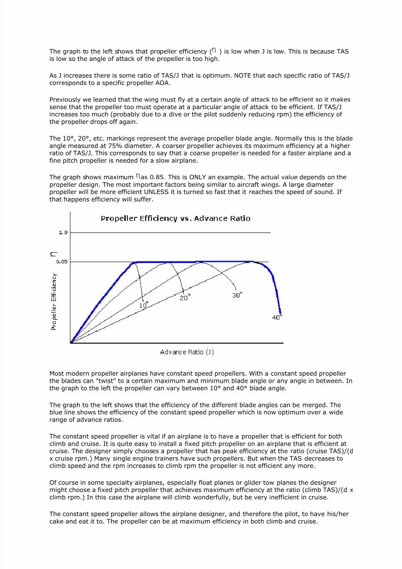
The graph to the left shows that propeller efficiency ( ) is low when J is low. This is because TASis low so the angle of attack of the propeller is too high.
As J increases there is some ratio of TAS/J that is optimum. NOTE that each specific ratio of TAS/Jcorresponds to a specific propeller AOA.
Previously we learned that the wing must fly at a certain angle of attack to be efficient so it makessense that the propeller too must operate at a particular angle of attack to be efficient. If TAS/Jincreases too much (probably due to a dive or the pilot suddenly reducing rpm) the efficiency of
the propeller drops off again.
The 10°, 20°, etc. markings represent the average propeller blade angle. Normally this is the blade
angle measured at 75% diameter. A coarser propeller achieves its maximum efficiency at a higherratio of TAS/J. This corresponds to say that a coarse propeller is needed for a faster airplane and a
fine pitch propeller is needed for a slow airplane.
The graph shows maximum as 0.85. This is ONLY an example. The actual value depends on the
propeller design. The most important factors being similar to aircraft wings. A large diameterpropeller will be more efficient UNLESS it is turned so fast that it reaches the speed of sound. If
that happens efficiency will suffer.
Most modern propeller airplanes have constant speed propellers. With a constant speed propellerthe blades can "twist" to a certain maximum and minimum blade angle or any angle in between. Inthe graph to the left the propeller can vary between 10° and 40° blade angle.
The graph to the left shows that the efficiency of the different blade angles can be merged. Theblue line shows the efficiency of the constant speed propeller which is now optimum over a wide
range of advance ratios.
The constant speed propeller is vital if an airplane is to have a propeller that is efficient for both
climb and cruise. It is quite easy to install a fixed pitch propeller on an airplane that is efficient atcruise. The designer simply chooses a propeller that has peak efficiency at the ratio (cruise TAS)/(d
x cruise rpm.) Many single engine trainers have such propellers. But when the TAS decreases toclimb speed and the rpm increases to climb rpm the propeller is not efficient any more.
Of course in some specialty airplanes, especially float planes or glider tow planes the designermight choose a fixed pitch propeller that achieves maximum efficiency at the ratio (climb TAS)/(d x
climb rpm.) In this case the airplane will climb wonderfully, but be very inefficient in cruise.
The constant speed propeller allows the airplane designer, and therefore the pilot, to have his/her
cake and eat it to. The propeller can be at maximum efficiency in both climb and cruise.
8/8/2019 Definition of Power
http://slidepdf.com/reader/full/definition-of-power 7/10
The Pa Graph
Recapping what we know so far; BHP is a constant value that the pilot sets by adjusting thethrottle and propeller controls to get a certain torque and rpm. Propeller efficiency varies with theratio TAS/J, except that it is constant over a wide range of this ratio if a constant speed propeller isinstalled.
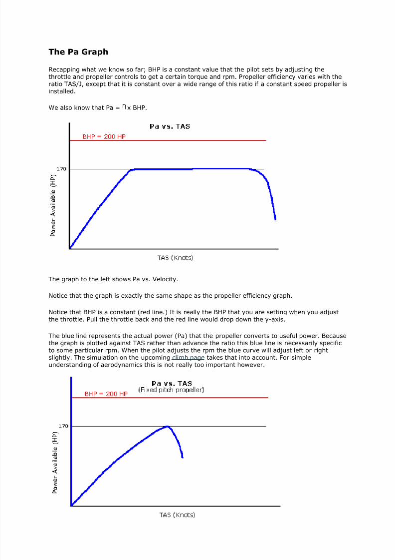
We also know that Pa = x BHP.
The graph to the left shows Pa vs. Velocity.
Notice that the graph is exactly the same shape as the propeller efficiency graph.
Notice that BHP is a constant (red line.) It is really the BHP that you are setting when you adjustthe throttle. Pull the throttle back and the red line would drop down the y-axis.
The blue line represents the actual power (Pa) that the propeller converts to useful power. Becausethe graph is plotted against TAS rather than advance the ratio this blue line is necessarily specificto some particular rpm. When the pilot adjusts the rpm the blue curve will adjust left or rightslightly. The simulation on the upcoming climb page takes that into account. For simpleunderstanding of aerodynamics this is not really too important however.
8/8/2019 Definition of Power
http://slidepdf.com/reader/full/definition-of-power 8/10
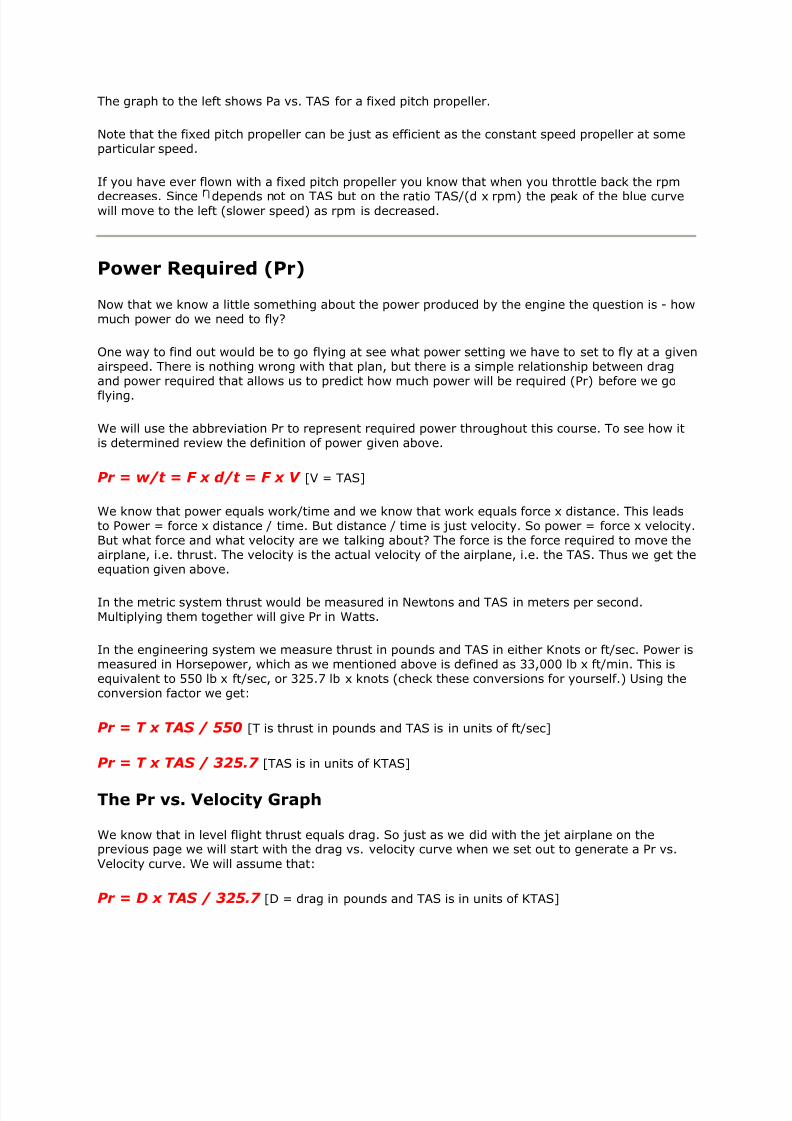
The graph to the left shows Pa vs. TAS for a fixed pitch propeller.
Note that the fixed pitch propeller can be just as efficient as the constant speed propeller at someparticular speed.
If you have ever flown with a fixed pitch propeller you know that when you throttle back the rpm
decreases. Since depends not on TAS but on the ratio TAS/(d x rpm) the peak of the blue curvewill move to the left (slower speed) as rpm is decreased.
Power Required (Pr)
Now that we know a little something about the power produced by the engine the question is - howmuch power do we need to fly?
One way to find out would be to go flying at see what power setting we have to set to fly at a givenairspeed. There is nothing wrong with that plan, but there is a simple relationship between dragand power required that allows us to predict how much power will be required (Pr) before we go
flying.
We will use the abbreviation Pr to represent required power throughout this course. To see how itis determined review the definition of power given above.
Pr = w/t = F x d/t = F x V [V = TAS]
We know that power equals work/time and we know that work equals force x distance. This leadsto Power = force x distance / time. But distance / time is just velocity. So power = force x velocity.But what force and what velocity are we talking about? The force is the force required to move theairplane, i.e. thrust. The velocity is the actual velocity of the airplane, i.e. the TAS. Thus we get theequation given above.
In the metric system thrust would be measured in Newtons and TAS in meters per second.Multiplying them together will give Pr in Watts.
In the engineering system we measure thrust in pounds and TAS in either Knots or ft/sec. Power ismeasured in Horsepower, which as we mentioned above is defined as 33,000 lb x ft/min. This isequivalent to 550 lb x ft/sec, or 325.7 lb x knots (check these conversions for yourself.) Using theconversion factor we get:
Pr = T x TAS / 550 [T is thrust in pounds and TAS is in units of ft/sec]
Pr = T x TAS / 325.7 [TAS is in units of KTAS]
The Pr vs. Velocity Graph
We know that in level flight thrust equals drag. So just as we did with the jet airplane on theprevious page we will start with the drag vs. velocity curve when we set out to generate a Pr vs.
Velocity curve. We will assume that:
Pr = D x TAS / 325.7 [D = drag in pounds and TAS is in units of KTAS]
8/8/2019 Definition of Power
http://slidepdf.com/reader/full/definition-of-power 9/10
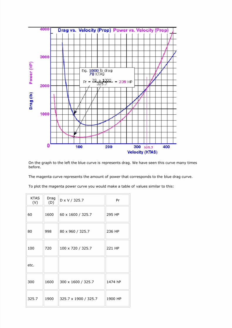
On the graph to the left the blue curve is represents drag. We have seen this curve many times
before.
The magenta curve represents the amount of power that corresponds to the blue drag curve.
To plot the magenta power curve you would make a table of values similar to this:
KTAS
(V)
Drag
(D)D x V / 325.7 Pr
60 1600 60 x 1600 / 325.7 295 HP
80 998 80 x 960 / 325.7 236 HP
100 720 100 x 720 / 325.7 221 HP
etc.
300 1600 300 x 1600 / 325.7 1474 hP
325.7 1900 325.7 x 1900 / 325.7 1900 HP

8/8/2019 Definition of Power
http://slidepdf.com/reader/full/definition-of-power 10/10
The table shows the process by which you can methodically turn a drag curve into a Pr curve.
Note the special speed of 325.7 KTAS. At that speed we get the result that "X" pounds of thrust
equals "X" horsepower. For this particular airplane there is 1900 pounds of drag at 325.7 KTAS so
1900 HP is required. Obviously these values will change with altitude and will be different for agiven airplane. The things that is true for all airplanes is that at speeds less than 325.7 KTAS the Prin units of horsepower will be less than the drag in units of pounds. Above 325.7 KTAS Pr is more
than drag. This fact has lead some people to claim that 325.7 is a "magic speed." The claim is thatairplanes that fly slower than this speed should be propeller airplanes and airplanes that fly faster
should be jets. The reasoning is that fuel flow is proportional to drag for a jet and power for apropeller airplane. The reasoning would be valid if both jet and propeller engines had the same
specific fuel consumption. But they do not so this reasoning is invalid.
We are now ready to explore flight for range and endurance for propeller airplanes.


![COMFTF-03 Definition (Power Point)-1[1]](https://img.pdfslide.us/doc/110x75/577d39921a28ab3a6b9a173c/comftf-03-definition-power-point-11.jpg)