Embed Size (px)
Citation preview

INCAS BULLETIN, Volume 10, Issue 1/ 2018 (P) ISSN 2066-8201, (E) ISSN 2247-4528
Definition and discussion of the
intrinsic efficiency of winglets
Dieter SCHOLZ
Aircraft Design and Systems Group (AERO),
Hamburg University of Applied Sciences,
Berliner Tor 9, 20099 Hamburg, Germany,
DOI: 10.13111/2066-8201.2018.10.1
Received: 24 November 2017/ Accepted: 03 December 2017/ To be Published: March 2018.
This is the PostPrint of the accepted manuscript.
Copyright © 2017.
Published by INCAS. This is an “open access” article under the CC BY-NC-ND license
(http://creativecommons.org/licenses/by-nc-nd/4.0)
Aerospace Europe CEAS 2017 Conference,
16th-20th October 2017, Palace of the Parliament, Bucharest, Romania,
Technical session Aircraft and Spacecraft Design I
Abstract: Three simple equations are derived to define the “Intrinsic Aerodynamic Efficiency of
Winglets” independent of the horizontal extension of the winglet and independent of the winglet’s
(relative) height. This Intrinsic Aerodynamic Efficiency allows a quick comparison of purely the
aerodynamic shape of winglets independent of the selected size chosen for a certain aircraft
installation. The Intrinsic Aerodynamic Efficiency is calculated in 3 steps: STEP 1: The relative total
drag reduction due to the winglet is converted into an assumed contribution of the winglet only on the
span efficiency factor. STEP 2: If the winglet also increases span, its performance is converted into
one without the effect of span increase. STEP 3: The winglet’s reduction in induced drag is compared
to a horizontal wing extension. If the winglet needs e.g. to be three times longer than the horizontal
extension to achieve the same induced drag reduction, its Intrinsic Aerodynamic Efficiency is the
inverse or 1/3. Winglet metrics as defined are calculated from literature inputs. In order to evaluate
winglets further, the mass increase due to winglets is estimated in addition to the reduction of drag on
aircraft level and fuel burn.
Key Words: wingtip, winglet, induced drag, wing mass, aircraft design
NOMENCLATURE
Upper Case Latin
A – aspect ratio, A = b2/S
A – coefficient in D = AV 2+BV
-2
B – coefficient in D = AV 2+BV
-2
C – aerodynamic coefficient
D – drag
L – lift
S – surface area
V – true airspeed
Lower Case Latin
b – wing span
c – chord
d – diameter
e – span efficiency or Oswald factor
g – earth acceleration
h – height of winglet; span increase
k – factor
m – mass

Dieter SCHOLZ 2
INCAS BULLETIN, Volume 10, Issue 1/ 2018
Greek Symbols
– difference, Delta
– air density
Subscripts
beef – “beefing up” of wing structure
co – cross over
CR – cruise
D – drag
D0 – zero-lift drag
Di – induced drag
eff – effective
F – fuel
h – horizontal
i – induced
L – lift
md – minimum drag
MTO – maximum take-off
MZF – maximum zero fuel
ref – reference (A/C without winglet)
t – tip of wing
W – wing
WL – winglet
1. INTRODUCTION
1.1 Motivation, Aim and Scope
Most passenger aircraft today have winglets. Winglets look stylish (Fig. 1). Winglets are
used to advertise the airline's logo like on the vertical tail (Fig. 2). Often winglets have fancy
names. The B737NG was equipped in 2014 with “Split Scimitar Winglets”. The B737 MAX
has “AT Winglets”, where “AT” stands for “Advanced Technology”. “AT Winglets” are
also split winglets [5]. Airbus calls the new blended winglets on the A320neo “Sharklets”
(2012). Sharklets are nothing more than “blended winglets” introduced on the B737NG
already in 2001. Blended winglets simply combine the horizontal wing with the vertical
winglet via a certain radius. A patent about “blended winglets” was already published in
1994 [6].
Fig. 1 – Different winglets on passenger aircraft:
A321 Sharklet [1], A350XWB Blended Winglet [2] and B737 MAX AT Winglet [3]
Fig. 2 – Airline Logos on Winglets: Southwest Airlines [4], Tui Fly, Air Berlin, Ryanair (own pictures)

3 Definition and discussion of the intrinsic efficiency of winglets
INCAS BULLETIN, Volume 10, Issue 1/ 2018
Manufacturers make various claims about the performance gain achieved due to their
winglets. The information is conveyed with press releases in an advertisement style. More
official data from manufacturers is usually missing and numbers in press releases may not
necessarily match up and make sense (see Appendix). When we look at claims about
winglets in scientific literature we find that claims even here do not match up (see
Chapter 1.3, 1.4 and 3.3). These are apparently already difficult questions: 1.) What is better,
a near vertical winglet or a span increase? It is said that the magnitude in performance gain
“depend[s] strongly on the design details of the baseline airplane and the [tip] device” [7].
Therefore: 2.) If two winglets differ in size or other geometric parameters, how can the
winglet's aerodynamic quality be measured and how can the two winglets still be compared?
A certain reduction in induced drag coefficient (at constant lift coefficient) can always be
reached, if the winglet is high enough and installed with a cant angle such that wing span is
also increased. However: 3.) Is there an overall benefit in drag and fuel burn due to the
winglet? This paper tries to answer these questions and more. Its aim is to raise awareness of
what winglets can achieve and what not. The paper will help readers to discuss winglet
performance based on sound scientific and practical knowledge. The equations given here
can also be used to make a preliminary aircraft design including winglets. Detailed aircraft
design with winglets will have to make use of Computational Fluid Dynamics (CFD) for
aerodynamics and loads and Finite Element Methods (FEM) for wing mass estimation. CFD
and FEM are beyond the scope of this paper.
1.2 Basic Aerodynamics of Winglets
Winglets are included in a design or added to an existing design to reduce drag. Different
suggestions are made in the literature to classify drag. These suggestions need to take into
account what methods are finally available to calculate the different drag components. There
is generally agreement to distinguish on the first level of the hierarchy between zero-lift drag
(drag independent of lift) and induced drag (drag due to lift; strongly depending also on
Mach number). Having said this, we need to state that zero-lift drag also depends on lift and
induced drag also depends on zero-lift drag, but this is beyond what should be discussed
here. Zero-lift drag can be broken down into profile drag, wave drag (strongly depending on
Mach number), interference drag, and miscellaneous drag (trim drag and additional drag).
Profile drag can in turn be subdivided into skin-friction drag and pressure drag. Details are
explained and calculation methods are given e.g. here: [8][9][10].
Winglets reduce induced drag (see below), but add zero-lift drag (due to additional
surface area) and interference drag (due to interference of the flow around the winglet and
the flow around the wing at the point where the two surfaces meet – unless the wing blends
well into the winglet). At transonic speeds the winglet will experience wave drag. The
winglet should be swept to limit wave drag.
Several explanations have been put forward to explain why winglets reduce induced
drag. A valid explanation is this: “To create ... lift, the wing pushes downward on the air it
encounters and leaves behind a wake ... forming two large vortices” [11] (Fig. 3). The energy
required to create this wake is reflected in the airplane's induced drag (also called vortex
drag). The basic method by which the vortex drag may be reduced is to increase the
horizontal or vertical extent of the wing. By increasing the wing dimensions, a larger mass of
air can be affected by a smaller amount to produce a given lift, and this leads to less energy
in the wake and lower induced drag [11]. A classical derivation [12][13] models the mass of
air affected by the wing as a cylinder with diameter, d = √2 b and length, l = V t, with flight
Dieter SCHOLZ 4
INCAS BULLETIN, Volume 10, Issue 1/ 2018
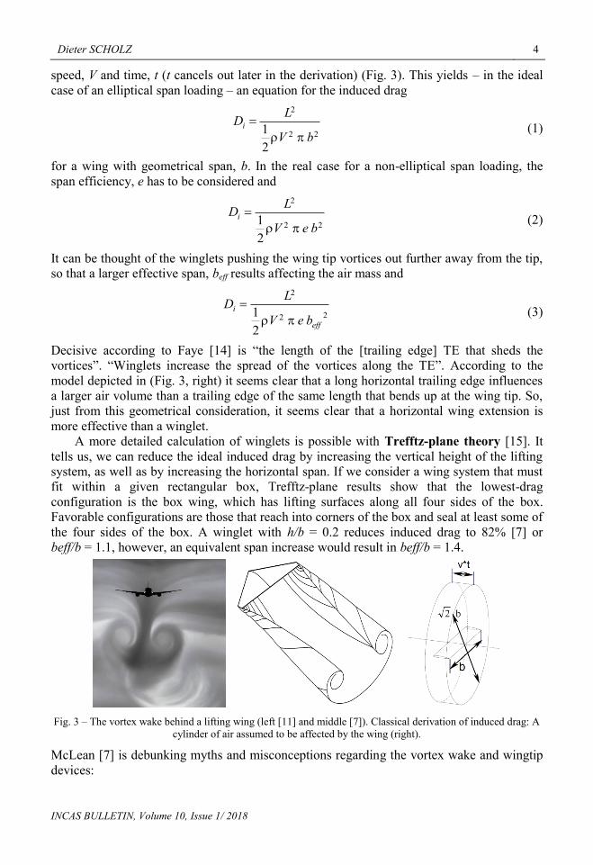
speed, V and time, t (t cancels out later in the derivation) (Fig. 3). This yields – in the ideal
case of an elliptical span loading – an equation for the induced drag
22
2
2
1bV
LDi
(1)
for a wing with geometrical span, b. In the real case for a non-elliptical span loading, the
span efficiency, e has to be considered and
22
2
2
1beV
LDi
(2)
It can be thought of the winglets pushing the wing tip vortices out further away from the tip,
so that a larger effective span, beff results affecting the air mass and
22
2
2
1eff
i
beV
LD
(3)
Decisive according to Faye [14] is “the length of the [trailing edge] TE that sheds the
vortices”. “Winglets increase the spread of the vortices along the TE”. According to the
model depicted in (Fig. 3, right) it seems clear that a long horizontal trailing edge influences
a larger air volume than a trailing edge of the same length that bends up at the wing tip. So,
just from this geometrical consideration, it seems clear that a horizontal wing extension is
more effective than a winglet.
A more detailed calculation of winglets is possible with Trefftz-plane theory [15]. It
tells us, we can reduce the ideal induced drag by increasing the vertical height of the lifting
system, as well as by increasing the horizontal span. If we consider a wing system that must
fit within a given rectangular box, Trefftz-plane results show that the lowest-drag
configuration is the box wing, which has lifting surfaces along all four sides of the box.
Favorable configurations are those that reach into corners of the box and seal at least some of
the four sides of the box. A winglet with h/b = 0.2 reduces induced drag to 82% [7] or
beff/b = 1.1, however, an equivalent span increase would result in beff/b = 1.4.
Fig. 3 – The vortex wake behind a lifting wing (left [11] and middle [7]). Classical derivation of induced drag: A
cylinder of air assumed to be affected by the wing (right).
McLean [7] is debunking myths and misconceptions regarding the vortex wake and wingtip
devices:

5 Definition and discussion of the intrinsic efficiency of winglets
INCAS BULLETIN, Volume 10, Issue 1/ 2018
“The vortex cores are often referred to as 'wingtip vortices', though this is a bit of a
misnomer.” “The vorticity that feeds into the cores generally comes from the entire span
of the trailing edge, not just from the wingtips. This “leads us to think we can influence
the induced drag by acting only on a very small part of the flow”. “There is no credible
evidence that any such device can provide a reduction in induced drag, beyond what can
be explained as the result of an increase in physical span when the device is added.”
“There is a common misunderstanding that a wingtip device reduces drag by producing
thrust on the surfaces of the device itself. This line of thinking is wrongly based on the
flowfield that would be there in the absence of the winglet. The real flowfield is
[however] altered considerably if the winglet is properly loaded.”
1.3 The “Classic” on Winglets in the Literature
Probably most cited when it comes to winglets is NASA-
TN-D-8260 by Richard T. Whitcomb [16]. This report
was one result of the Aircraft Energy Efficiency (ACEE)
program initiated by NASA and the Department of
Energy (DOE) after the fuel crisis. Whitcomb was an
outstanding engineer. He is listed in the “NACA and
NASA Langley Hall of Honor” [17] Among many other
inventions he is honored for the winglet: “Wing-tip
vertical end-plates had been used in efforts to reduce
drag many years before Whitcomb's design efforts, but
his ingenious and detailed analysis led to special
tailoring of such devices, which proved to significantly
reduce drag at cruising speeds. He called his invention
'winglets'“ [18]. Whitcomb, 1976:
“For the [two] configurations investigated the
winglets reduce the induced drag by about 20%
with a resulting increase in wing lift-drag ratio of
roughly 9 percent ... This improvement in lift-drag
ratio is more than twice as great as that achieved
with the comparable wing-tip extension”. “A
comparison ... with ... a wing-tip extension ...
results in approximately the same increase in
bending moment at the wing-fuselage juncture as
did the addition of the winglets”. [16]
Many have taken Whitcomb's statement without looking at the geometry that got analyzed.
Whitcomb compares (incorrectly) two arbitrary chosen wing tip devices that are not
comparable: a) a horizontal tip extension of hh = 0.076 m and b) a near vertical split winglet
ct = 0.203 m up and 0.23.ct down and hence with total height h = 1.23
.ct = 0.250 m, (Fig. 4).
Similar criticism can be found in the literature:
“It should be noted that these results were obtained for a particular wing, winglet, and
wingtip extension. Potential drag savings and moment distributions depend strongly on
the geometry of the surfaces”. “The tip modification [of the B747-400] increased the
cruise L/D approximately 4 percent (less than half of the upper limit of 9 percent
suggested by wind tunnel tests in the ACEE program ...), with much of the improvement
coming from the span extension”. [11]
Fig. 4 – Whitcomb's winglet [16]

Dieter SCHOLZ 6
INCAS BULLETIN, Volume 10, Issue 1/ 2018
“Whitcomb's ... results of wind-tunnel tests [were] comparing configurations that were
not comparable”. “[His] rule of thumb has not been borne out by studies since then”. [7].
1.4 More from Fundamental Literature
It has always been the question how a winglet compares to a span extension with respect to
drag reduction and mass increase.
As a rule of thumb the ratio between winglet height and comparable span extension is
discussed.
• Larson, 2001 [19] (original source unknown):
“One rule of thumb says that for an increase in wing-bending force equal to that of a
one-foot increase in span, a wing's structure can support a three-foot winglet that
provides the same gain as a two-foot span extension”. That is: Same drag reduction at
half the mass and winglet of ratio 1.5.
• Jones, 1980 [20] quoting Prandtl, 1933 [21]:
“[With] a constraint on the integrated bending moments, ... a 10-percent reduction of
induced drag can be achieved by a 10-percent increase of wing span accompanied by a
more highly tapered loading”
• Jones, 1980 [20]:
“The same result can be obtained by a 15-percent vertical extension. Thus, it appears
that with ideal wing shapes similar reductions of induced drag can be achieved by either
horizontal or vertical tip extensions”. That is: Same drag reduction at same mass and
winglet of ratio 1.5.
• McLean, [7] quoting Jones, 1980 [20]:
“The calculations indicate that horizontal span extensions and vertical winglets offer
essentially the same maximum induced-drag reduction when the spanloads are
constrained so that there is no increase in 'structural weight'. They also indicate that to
achieve a given level of drag reduction, a vertical winglet must be nearly twice as large
as a horizontal span extension”. That is: Same drag reduction at same mass and winglet
of ratio 2.0. As we will see below this last rule of thumb is the one that comes quite close
to the truth.
1.5 More Literature
NASA-TN-D-8260 by Richard T. Whitcomb was followed by NASA-TP-1020 in 1977 [22]
it includes many diagrams about span efficiency factor increase versus wing root bending
moment increase. Among the many aircraft design textbooks it seems that only
Gudmundsson (2014) [23] gives particular attention to the design of winglets. A design
method based on [23] is used in a case study retrofitting winglets to the Dassault Falcon 10
business jet [24]. Many papers report about a detailed aerodynamic analysis of a winglet of a
specific geometry, however, with little information about how these findings can be
generalized. Only one such study should be mentioned [25]. It compares a certain winglet
with a raked tip against the wing reference in the wind tunnel and with CFD. Quite a
complete overview about passenger aircraft and their winglets is given in [11], but as the
matters stand, also with little data.

7 Definition and discussion of the intrinsic efficiency of winglets
INCAS BULLETIN, Volume 10, Issue 1/ 2018
2. WINGLET WISDOM
2.1 Fundamentals
• Winglets reduce induced drag, but add zero-lift drag due to the fact that they add wetted
area to a given wing area. In contrast, a span extension (aspect ratio increase) will be
done at constant wing area, because also the new area at the tip contributes to the lift and
as such the area added on the wing at one location can be subtracted at another location.
• Drag, D is a function of True Air Speed, V. Drag is calculated from D = AV 2 + BV
-2.
This is the speed polar. The Minimum Drag speed, Vmd = (B/A) 1/4
. It depends on the zero-
lift drag coefficient CD0, span efficiency factor e and aircraft mass in cruise mCR. A
increases with CD0. B increases with mCR and decreases with e. For a good winglet that
does not increase CD0, does not increase wing mass and hence does not increase mCR, drag
D is reduced and Vmd is reduced as well. [26]
• The Crossover Speed, Vco on the speed polar is the speed at which the speed polars of the
aircraft without winglets and with winglets intersect. With the Crossover Speed it is easy
to make the tradeoff between the zero-lift drag penalty and the induced-drag benefit.
Below this speed, winglets are beneficial, whereas above it they are detrimental. Flying at
the Crossover Speed means to fly at a speed where the benefit in induced drag due to
winglets is equal to the zero-lift drag penalty. The more the induced drag can be reduced
for a given increase in zero-lift drag, the higher the Crossover Speed and the more useful
the winglet, because of its wide useful speed range. (See also [27])
• Winglets work best at high lift coefficients (i.e. speeds speed below the Crossover
Speed). This is the case for take-off, climb, approach and landing.
• Winglets are detrimental at very low lift coefficients which occur at high cruise speed
combined with low altitude and low aircraft mass (small payload and small fuel quantity).
• A winglet adds wing bending to the wing loads. A span increase adds wing bending to the
wing loads in much the same way as the winglet and adds shear forces. Beefing up shear
webs does not generally add much wing mass, but it could be expensive in retrofit
applications [7].
• For unlimited wing span, a span increase is in almost all situations superior to a winglet.
For passenger aircraft raked tips have been used [7]. For extremely high aspect ratios
(sailplanes) winglets where found more beneficial than a further span increase [27].
• For limited wing span, however, the winglet is a good way to reduce induced drag. Wing
span limits at airports are due to the "FAA Airplane Design Group" and the "ICAO
Aerodrome Reference Code". Both are identical with respect to the maximum wing span
definition (Table 1).
Table 1 – ICAO Aerodrome Reference Code [28]
code letter wingspan
A < 15 m
B 15 m but < 24 m
C 24 m but < 36 m
D 36 m but < 52 m
E 52 m but < 65 m
F 65 m but < 80 m

Dieter SCHOLZ 8
INCAS BULLETIN, Volume 10, Issue 1/ 2018
2.2 Pros and Cons
• Benefits of winglets:
o Induced drag reduction
o Larger lift curve slope (due to larger effective span)
o Reduced fuel burn
o Increased payload
o Increased maximum range
o Reduced takeoff field length due to improved second segment climb
o Meet gate clearance with minimal performance penalty
o Appearance and product differentiation
o Increased residual aircraft value (add 700000 USD for a B737NG at installation and
depreciate together with aircraft over time) [29]
Negative factors of winglets:
o Increased wetted area leading to increased zero-lift drag
o Junction flows leading to increased interference drag
o Mass increase due to the device itself
o Mass increase due to the mass of attachment fittings
o Increased difficulty in cross-wind landings
o Increased loads on the wing with side slip
o Increased tendency to flutter due to added mass at the wing tips
o Mass increase to the existing wing structure (“beefing up”) due to larger static loads,
more demanding flutter loads and fatigue requirements
o Increased costs for the manufacturer (non-recurring costs and recurring costs)
o Increased costs for the airline (purchase costs, maintenance costs – 6.5 hours
scheduled maintenance per year [29])
o Increased development risk
o Split winglets (that extend below the wing) are prone to damage from ground service
equipment (this could lead to unscheduled maintenance costs, delays and
cancellations)
Compare also with [30].
2.3 General Hints
These hints are largely based on [7].
The induced-drag reduction that can actually be achieved in most applications typically
falls significantly short of the ideal.
When a winglet is included in the design of an all-new wing, the structural mass penalty
of “beefing up” the wing structure must be paid in full. On an existing airplane, flight
testing will sometimes have established that the wing has excess structural margin that
can be “used up” by the addition of a tip device.
If the twist distribution of the existing wing was optimized for operation without a
winglet, the benefit available from the addition of a winglet will usually be substantially
less than it would have been if the wing could have been re-optimized.
When horizontal span extensions and vertical winglets are designed, it is found that they
offer the same induced-drag reduction when the same wing bending load occurs. So, in
terms of the trade between drag reduction and mass increase (to the wing structure),
horizontal span extensions and vertical winglets have almost the same performance
potential.

9 Definition and discussion of the intrinsic efficiency of winglets
INCAS BULLETIN, Volume 10, Issue 1/ 2018
To achieve the same induced-drag reduction, a vertical winglet must be considerably
higher than the span increase. This is expressed with the parameter kWL (see Chapter 3.1).
Note: This adds more winglet mass than horizontal tip mass.
The percentage drag reduction shows a diminishing rate of return with increasing device
size.
The percentage mass increase tends to be roughly linear with size.
Because of the mass increase, the percentage fuel-burn reduction is less than the
percentage drag reduction.
The increase in maximum range depends on what is limiting the range. If the range is
limited by maximum take-off mass (MTOM), the mass increase due to the winglet will
subtract directly from the fuel that can be carried, and the increase in range may be very
small. Only if the aircraft takes-off from a short runway or is climb-limited winglets help
to carry more mass (and fuel) out of the airport which extends range.
Tip devices of a wide variety of types seem to have very similar potential with regard to
the drag/mass trade (at the same value of h/b).
Winglets on the upper wing increase effective dihedral; this needs to be accounted for in a
new wing design; retrofits have to cope with (known) consequences.
2.4 Hints to Detailed Design
These hints are largely based on [7].
Part-chord winglets follow the strategy of integrating an outboard chord distribution
consistent with the desired span load with an existing trapezoidal wing that has more
chord than it needs at the tip (e.g. due to aileron integration).
Blended winglets have no discontinuous change in chord at the junction as there would be
with a conventional part-chord winglet, but within the blending region, the chord
decreases rapidly and smoothly, so that the chord distribution from there out is similar to
that of a part-chord winglet.
Any retreat from the corners of the box (due to “blending” with a radius in the junction
between the winglet and the wing) increases ideal induced drag, but avoids interference
drag associated with sharp corners and reduces wetted area a little.
For other blended winglet parameters (e.g. the winglet radius), see equations in [6].
Split winglets have the winglet height split into two equally separated winglets above and
below the wing, each winglet span is only half the size and bending moments are half the
original. If the winglet's chord is sized to the load carried, the split winglet needs only
half as much chord as the single winglet and will have half the mass. However, split
winglets produce only about 90% of the induced drag reduction compared with a standard
winglet of the same total height.
3. ESTIMATING WINGLET AERODYNAMICS
3.1 Derivation of the Intrinsic Aerodynamic Efficiency of Winglets: 1/kWL
The simplest approach in understanding winglets is to consider the effect of the winglets
equal to that of a wing that prolongs its span with the size of the winglets, as in Fig. 3. See
also [31], [10].

Dieter SCHOLZ 10
INCAS BULLETIN, Volume 10, Issue 1/ 2018
Fig. 5 – Simple geometrical consideration for winglets evaluation
The following relations can be written:
WL
L
eff
LWLiD
LiD
eff
Ae
C
eA
CC
Ae
CC
b
h
b
b
22
,,
2
, ,
21
eb
be
A
Ae
effeff
WL
2
(4)
Hence eb
heWL
2
21 (5)
This simple geometrical consideration aids in understanding the phenomenon, but it is not
accurate enough, because it would yield the same result for any tip device with ratio h/b.
Proposed is a penalization via a factor kWL. The height of the winglet is divided by a certain
parameter. This is exactly the parameter or “ratio” that appears again and again in literature
and which was discussed in Chapter 1.4 (where it appeared as 1.5 or 2.0).
ekeb
h
ke WLe
WL
WL
,
2
21 ,
2
,
21
b
h
kk
WL
WLe (6)
If the winglet with its height has the same effect as a span increase, then kWL = 1.0 and Eq. 6
(left) is the same as Eq. 5. This is the geometrical equivalence of the winglet. I.e. the winglet
sticking up is as good as folding it down. If, however, the winglet height needs to be divided
by e.g. 2 and only this reduced height taken as a span increase gives the performance of the
winglet, then kWL = 2.0. This is value is proposed by McLean [7] and Howe [32]. The inverse
1/kWL is called the Intrinsic Aerodynamic Efficiency of the Winglet. It is calculated from
STEP 1, STEP 2 and STEP 3 as explained below. kWL is independent of winglet height and
shows simply how good the winglet is designed in detail. e is the span efficiency of the basic
wing, eWL is the span efficiency of the wing with winglet. ke,WL is the winglets contribution to
span efficiency of the wing with winglet. kWL is calculated from Eq. 6 (right) as
STEP 3: 1
12
,,
vWLe
WLkb
hk (7)
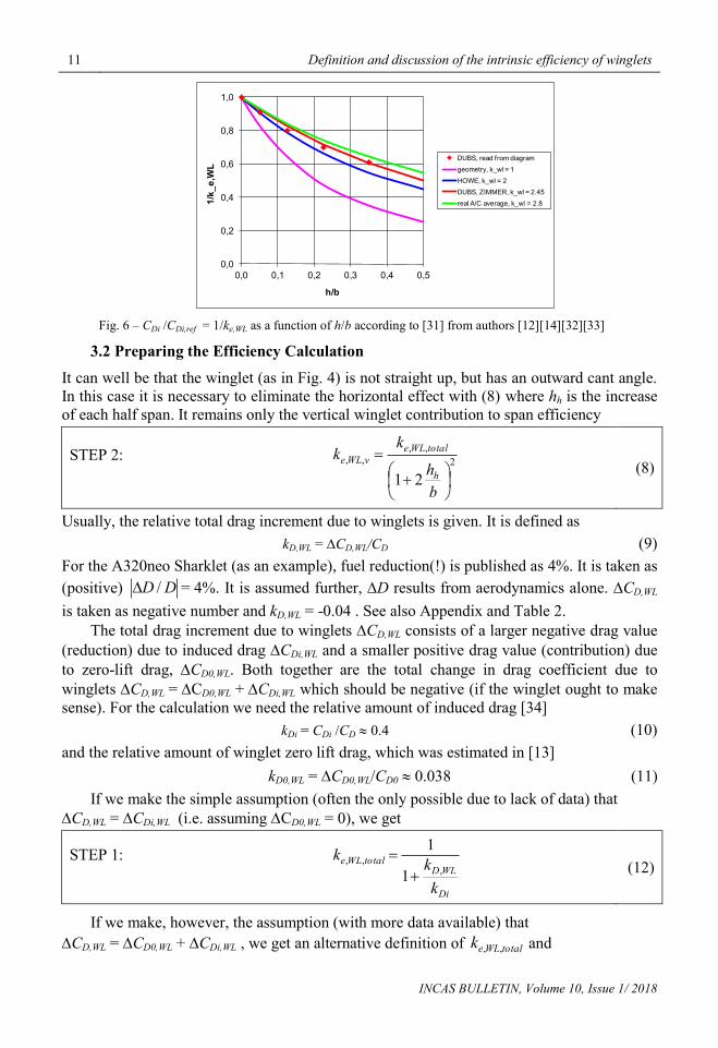
Fig. 6 is calculated from Eq. 6 (right). The pure geometric consideration yields a curve
for kWL = 1. Howe [32] and McLean [7] assume that kWL = 2 as a rule of thumb. Data from
Dubs [12] and Zimmer [33] can be represented with kWL = 2.45. Real aircraft (A/C) seem to
be even less efficient. An evaluation of data in [14] was done in [31] and resulted on average
in kWL = 2.8.
11 Definition and discussion of the intrinsic efficiency of winglets
INCAS BULLETIN, Volume 10, Issue 1/ 2018
Fig. 6 – CDi /CDi,ref = 1/ke,WL as a function of h/b according to [31] from authors [12][14][32][33]
3.2 Preparing the Efficiency Calculation
It can well be that the winglet (as in Fig. 4) is not straight up, but has an outward cant angle.
In this case it is necessary to eliminate the horizontal effect with (8) where hh is the increase
of each half span. It remains only the vertical winglet contribution to span efficiency
STEP 2: 2
,,
,,
21
b
h
kk
h
totalWLe
vWLe (8)
Usually, the relative total drag increment due to winglets is given. It is defined as
kD,WL = CD,WL/CD (9)
For the A320neo Sharklet (as an example), fuel reduction(!) is published as 4%. It is taken as
(positive) DD / = 4%. It is assumed further, D results from aerodynamics alone. CD,WL
is taken as negative number and kD,WL = -0.04 . See also Appendix and Table 2.
The total drag increment due to winglets CD,WL consists of a larger negative drag value
(reduction) due to induced drag CDi,WL and a smaller positive drag value (contribution) due
to zero-lift drag, CD0,WL. Both together are the total change in drag coefficient due to
winglets CD,WL = CD0,WL + CDi,WL which should be negative (if the winglet ought to make
sense). For the calculation we need the relative amount of induced drag [34]
kDi = CDi /CD 0.4 (10)
and the relative amount of winglet zero lift drag, which was estimated in [13]
kD0,WL = CD0,WL/CD0 0.038 (11)
If we make the simple assumption (often the only possible due to lack of data) that
CD,WL = CDi,WL (i.e. assuming CD0,WL = 0), we get
STEP 1:
Di
WLDtotalWLe
k
kk
,,,
1
1
(12)
If we make, however, the assumption (with more data available) that
CD,WL = CD0,WL + CDi,WL , we get an alternative definition of totalWLek ,, and
0,0
0,2
0,4
0,6
0,8
1,0
0,0 0,1 0,2 0,3 0,4 0,5
1/k_e,WL
h/b
DUBS, read from diagram
geometry, k_wl = 1
HOWE, k_wl = 2
DUBS, ZIMMER, k_wl = 2.45
real A/C average, k_wl = 2.8

Dieter SCHOLZ 12
INCAS BULLETIN, Volume 10, Issue 1/ 2018
ALTERNATIVE STEP 1:
Di
WLDWLD
Di
totalWLe
k
kk
k
k,
,0
,,
11
1
1
(13)
STEP 1 (12) lumps the zero lift drag of the winglets CD0,WL into the simplified induced drag
calculation. On the other hand, the ALTERNATIVE STEP 1 (13) separates the zero lift drag
and induced drag effects of the winglets. Therefore, the detrimental additional zero lift drag
of the winglets CD0,WL does not show up in ke,WL,total from (13). With the assumption
CD0,WL = 0 and hence kD0,WL = 0, Eq. 13 simplifies to Eq. 12. For standard parameters
(4% drag reduction, ...) as given above ke,WL,total = 1.11 from Eq. 12 and improves to
ke,WL,total = 1.19 in case of Eq. 13. This reduces kWL by a factor of 0.61 as calculated from (7).
This means in this alternative approach, e.g. a kWL = 2.8 (Fig. 6) could reduce to kWL = 1.7 if
the zero lift drag of the winglets is excluded. This would bring kWL in line with values in the
interval 1.5 ... 2.0 given by Jones [20] and McLean [7].
4/
11
11
md
Di
VV
k
, from aircraft design: 316.13/1 4 mdVV (14)
The value kDi = 0.4 as proposed by Kroo [34] is obtained for V/Vmd = 1.11. This can be seen
as a typical value in aircraft design. Derivations of (13) and (14) as well as background
information is given in [13].
The (standard) method with Eq. 12 has been applied to Whitcomb's winglet from
Fig. 4. kWL = 2.7 was obtained [13] with the standard method based on (12). This is well in
the usual range. The Intrinsic Aerodynamic Efficiency is 1/2.7 = 0.37 only. As such it is not
aerodynamically superior to a span increase! This is in contrast to what Whitcomb seems to
convey in [16]!
3.3 Intrinsic Aerodynamic Efficiency of Winglets Calculated from Literature Data
Now kWL and the Intrinsic Aerodynamic Efficiency of Winglets 1/kWL can be calculated.
Table 2 – Drag reduction and geometry of wing tip devices for selected passenger aircraft
(Geometry from: Aircraft Characteristics for Airport Planning of the respective aircraft)
No. aircraft Fig. DD / Source bold [m] bnew [m] bICAO
[m] h [m] hh [m]
1 747-400 winglet 7 3.5% [14] 59.63 64.40 65 3.73 2.39
2 737-800 blended winglet 2 3.8% [14] 34.32 35.79 36 2.60 0.73
3 MD-11 extended winglet 7 3.5% [14] 51.52 51.97 52 2.87 0.23
4 A320neo Sharklet 1 4.0% [35][36] 35.80 35.80 36 2.43 0.00
5 A380plus split winglet 7 4.0% [44] 79.75 82.15 80 4.70 1.20
Table 3 – Intrinsic Aerodynamic Efficiency of Winglets 1/kWL calculated for selected passenger aircraft
No. aircraft h/b hh/b totalWLek ,, vWLek ,, kWL 1/ kWL
1 747-400 winglet 6.25% 4.00% 1.096 0.940 --- ---
2 737-800 blended winglet 7.58% 2.14% 1.105 1.016 18.94 5.3%
3 MD-11 extended winglet 5.57% 0.44% 1.096 1.077 2.95 33.9%
4 A320neo Sharklet 6.79% 0.00% 1.111 1.111 2.51 39.8%
5 A380plus split winglet 5.89% 1.50% 1.111 1.047 5.06 19.8%

13 Definition and discussion of the intrinsic efficiency of winglets
INCAS BULLETIN, Volume 10, Issue 1/ 2018
Data from literature is used. Results are given in Table 2 and Table 3.
Fig. 7 – B747-400 winglet (A. Pingstone, Wikimedia, CC BY-SA),
MD-11 winglet (Stefano F., Flickr, CC BY-SA), A380plus winglet [44]
Fig. 8 – Relative drag reduction and Intrinsic Aerodynamic Efficiency of Winglets. Data from Table 2 and 3.
With the addition of winglets, almost all aircraft from Table 2 try to make full use of the
ICAO span limits (Table 1) allowing only for a small safety margin. One exception is the
A380plus violating the span limit of 80 m with the winglet. The A320 made already full use
of the 36 m (with a little margin), so that the A320neo had to use a vertical winglet. All
aircraft aim for a very similar relative drag reduction of 3.8% on average. The B747-400 has
the largest relative horizontal span increase. Eliminating the span effect, nothing is left
(ke,WL,v < 1). From this it seems, the 747-400 would have been better off with a pure span
increase instead of adopting a winglet. Almost the same is true for the 737-800. The
A320neo and the MD-11 make no or very little use of span increase. Their drag reduction is
due to the (near) vertical winglet alone. With this, these two aircraft achieve a typical ke,WL of
2.5 respectively 3. This is equivalent to an Intrinsic Aerodynamic Efficiency of the Winglet
of 34% respectively 40%.

Dieter SCHOLZ 14
INCAS BULLETIN, Volume 10, Issue 1/ 2018
4. ESTIMATING MASS INCREASE DUE TO WINGLETS
With this Chapter, we go beyond the title of the paper. The mass increase due to winglets,
m is estimated from "beefing up" the wing, resulting in mbeef and the additional mass due
to the two winglets (left and right wing tip) themselves, mWL .
WLbeef mmm
mbeef version 1 ([7]: B737NG ... Fig. 4.3):
CR
beef
beefmm
mk
,
, 2
MZFMTOCR
mmm
,
5.0...1.0,
,
WLD
beefm
k
k
CRbeefmbeef mkm , , WLDbeefm kk ,, )5.0...1.0(
(15)
mbeef version 2 (derived from [22] with details of the derivation in [13]):
refWtotalWLebeef mkm ,,, )1(44.0 (16)
mbeef version 3 (with mW (x) being any kind of equation or method to estimate wing mass):
)()( bmbmm WeffWbeef
(17)
mWL version 1 (A320neo [31] ... B737NG [7]):
hh
mm WL
WL
,
kg/m111... kg/m83
h
mWL
, 1
2,, vWLeWL kk
bh
mWL version 2 (A320neo [31] ... B737NG [7]):
WL
WL
WLWL S
S
mm
,
22 kg/m200...kg/m180
WL
WL
S
m
, 2
tWL
chS
,
12
,, vWLeWL kkb
h
ct : cord of wing tip; assumed chord at tip of winglet: cWL,t 0 .
5. ESTIMATING THE DRAG AND FUEL BURN REDUCTION DUE TO
WINGLETS
The speed polar D = f(V) is used when dealing with aircraft performance. The speed polar
follows directly from the lift and drag equation and contains the terms (just abbreviations)
called A and B [26]. The speed polar is
22 BVAVD where WD SCA 02
1
eAS
gmB
222
22 VBVAD WLWLWL WWLDWL SCA ,02
1
WLeW
WLkeAS
gmmB
,
22)(2
Drag reduction: WLDDD AAWL , if assumed that 0,0 DWLD CC
.
Relative fuel burn reduction D
D
m
m
F
F

15 Definition and discussion of the intrinsic efficiency of winglets
INCAS BULLETIN, Volume 10, Issue 1/ 2018
follows from drag reduction including also the effect of mass increase and zero-lift drag
increase. Nonlinear effects on fuel mass due to the Breguet range equation have been ignored
at this point.
6. SUMMARY
A method has been presented to calculate the “Intrinsic Aerodynamic Efficiency of
Winglets” 1/kWL. It lumps all aerodynamic winglet characteristics (from zero-lift drag and
from induced drag) into this single parameter. A constant typical cruise lift coefficient is
assumed because changes in aircraft mass are not considered. If e.g. the winglet needs to be
3 times larger compared to a horizontal span increase with the same overall aerodynamic
effect (kWL = 3), its Intrinsic Aerodynamic Efficiency of the Winglet would be the inverse or
1/3. A simple method is given to estimates the mass increase due to winglets. Finally, the
overall drag reduction can be calculated from the speed polar. This yields also an estimate of
the relative fuel burn reduction due to winglets.
ACKNOWLEDGEMENTS
Thanks to Nemo Juchmann from Hamburg University of Applied Sciences for his
contribution to the literature review and the inspiring discussions.
REFERENCES
[1] * * * Airbus, URL: http://www.airbus.com/newsroom/photo-gallery.html, 2017.
[2] A. Bouquet, The Graceful Sharklet of Airbus A350 XWB, posted on 2014-01-13, URL:
http://www.talkativeman.com/graceful_sharklet_of_airbus_a350_xwb, 2014.
[3] * * * Boeing, URL: http://www.boeing.com/commercial/737max/#/gallery, 2017.
[4] B. Granucci, The Detailed Changes of Southwest's New Scheme and Their Historic Past Paints, URL:
http://www.nycaviation.com/2014/09/southwest-airlines-unveils-new-livery-branding/35747, 2017.
[5] C. Brady, The Boeing 737 Technical Site – Winglets; URL: http://www.b737.org.uk/winglets.htm, 2017.
[6] L. B. Gratzer, Blended Winglet, United States, Patent No 5348253, URL:
https://www.google.com/patents/US5348253, 1994.
[7] D. McLean, Wingtip Devices: What They Do and How They Do It, Boeing Performance and Flight Operations
Engineering Conference, Boeing, Article 4, URL:
http://www.smartcockpit.com/docs/Wingtip_Devices.pdf, 2005.
[8] D. Scholz, Drag Prediction, Aircraft Design, Lecture Notes, Hamburg University of Applied Sciences, URL:
http:/HOOU.ProfScholz.de, 2017.
[9] D. Scholz, Appendix A: Several Approaches to Drag Estimation, Aircraft Design, Lecture Notes, Hamburg
University of Applied Sciences, – URL: http:/HOOU.ProfScholz.de, 2017.
[10] D. Scholz, Appendix B: Estimating the Oswald Factor from Basic Aircraft Geometrical Parameter, Aircraft
Design, Lecture Notes; Hamburg University of Applied Sciences, – URL: http:/HOOU.ProfScholz.de,
2017.
[11] * * * National Research Council, Assessment of Wingtip Modifications to Increase the Fuel Efficiency of Air
Force Aircraft, National Academy of Sciences; Washington, DC, USA, – URL:
http://www.nap.edu/catalog/11839.html, 2007.
[12] F. Dubs, Hochgeschwindigkeits-Aerodynamik, Birkhäuser, Basel, 1975.
[13] D. Scholz, Winglet Calculations, Memo, Aircraft Design and Systems Group (AERO), Hamburg University
of Applied Sciences, Berliner Tor 5, 20099 Hamburg; Germany, OPerA_M_Winglet_Calculations_17-
09-04, URL: http://reports-at-aero.ProfScholz.de, 2017.
[14] R. Faye, R. Laprete, M. Winter, Blended Winglets for Improved Airplane Performance, AERO Magazin, 17,
pp. 18–31, URL: http://www.boeing.com/commercial/aeromagazine/aero_17, 2002.
[15] I. Kroo, Induced Drag and the Trefftz Plane, Applied Aerodynamics - A Digital Textbook, Desktop
Aeronautics; Stanford, CA, USA. - URL:
http://docs.desktop.aero/appliedaero/potential3d/InducedDrag.html, 2007.

Dieter SCHOLZ 16
INCAS BULLETIN, Volume 10, Issue 1/ 2018
[16] R. T. Whitcomb, A Design Approach and Selected Wind-Tunnel Results at High Subsonic Speeds for Wing-
Tip Mounted Winglets, NASA-TN-D-8260, Report No. L-10908, NASA Langley Research Center,
Hampton, VA 23665, USA, URL: http://ntrs.nasa.gov/archive/nasa/casi.ntrs.nasa.gov/19760019075.pdf,
1976.
[17] NASA; 2017: NACA and NASA Langley Hall of Honor. – URL: https://www.nasa.gov/langley/hall-of-
honor
[18] R. T. Whitcomb, – URL: https://www.nasa.gov/langley/hall-of-honor/richard-t-whitcomb, NASA, 2017.
[19] G. C. Larson, How Things Work: Winglets, Air & Space Magazine, 2001-09-01, URL:
http://www.airspacemag.com/flight-today/how-things-work-winglets-2468375, 2001.
[20] R. T. Jones, T. A. Lasinski, Effect of Winglets on the Induced Drag of Ideal Wing Shapes, NASA TM-81230,
Report No. A-8329, Ames Research Center, NASA, Moffett Field, CA, USA, – URL:
http://www.engbrasil.eng.br/artigos/art60.pdf, 1980.
[21] L. Prandtl, Über Tragflügel des kleinsten Induzierten Widerstandes, Zeitschrift für Flugtechnik und
Motorluftschiffahrt, 24. Jg. S. 305-306, – Reprinted in: W. Tollmien, H. Schlichting, H. Görtler (Ed.),
1961, Gesammelte Abhandlungen; Springer-Verlag; URL: https://doi.org/10.1007/978-3-662-11836-
8_40, 1933.
[22] H. H. Heyson, G. D. Riebe and C. L. Fulton, Theoretical Parametric Study of the Relative Advantages of
Winglets and Wing-Tip Extensions, NASA-TP-1020, Report No. L-11679, NASA Langley Research
Center, Hampton, VA 23665, USA, URL:
https://ntrs.nasa.gov/archive/nasa/casi.ntrs.nasa.gov/19770026168.pdf, 1977.
[23] S. Gudmundsson, General Aviation Aircraft Design: Applied Methods and Procedures, Butterworth-
Heinemann, – ISBN: 978-0123973085, 2014.
[24] P. R. Rademacher, Winglet Performance Evaluation through the Vortex Lattice Method, Master Thesis,
Embry-Riddle Aeronautical University, Daytona Beach, FL, USA. – URL:
http://www.amcpilot.com/files/Phil_Thesis.pdf, 2014.
[25] T.-R. Teschner, A Comparative Study between Winglet and Raked Wingtip Wing Configurations, Bachelor
Thesis, Department of Automotive and Aeronautical Engineering, Hamburg University of Applied
Sciences, – URL: http://edoc.sub.uni-
hamburg.de/haw/volltexte/2013/1977/pdf/A_comparative_study_between_winglet_and_raked_wingtip_w
ing_configurations.pdf, 2012.
[26] D. Scholz, Flight Mechanics, Lecture Notes, Hamburg University of Applied Sciences, URL:
http:/fml.ProfScholz.de, 2017.
[27] M. D. Maughmer, Design of Winglets for High-Performance Sailplanes, Journal of Aircraft, 40, no. 6, 2003-
11/12, URL: https://doi.org/10.2514/2.7220, 2003.
[28] * * * ICAO, Aerodrome Standards: Aerodrome Design and Operations, based on ICAO Annex 14, Third
Edition, 1999-07, URL:
https://www.icao.int/safety/Implementation/Library/Manual%20Aerodrome%20Stds.pdf, URL:
http://www.skybrary.aero/index.php/ICAO_Aerodrome_Reference_Code, 1999.
[29] * * * Aviation Partners Boeing, Winglets, – URL: http://www.aviationpartnersboeing.com, 2007.
[30] F. Müller, Flugzeugentwurf: Entwurfssystematik, Aerodynamic, Flugmechanik und Auslegungsparameter
für kleinere Flugzeuge, Dieter Thomas Verlag, Fürstenfeldbruck, Germany, 2003.
[31] M. Nita, D. Scholz, Estimating the Oswald Factor from Basic Aircraft Geometrical Parameters,
Publikationen zum DLRK 2012, (Deutscher Luft- und Raumfahrtkongress, Berlin, 10. - 12. September
2012), URN: urn:nbn:de:101:1-201212176728, DocumentID: 281424; URL: http://OPerA.ProfScholz.de
[32] D. Howe, Aircraft Conceptual Design Synthesis; Professional Engeneering Publishing, London, GB, 2000.
[33] H. Zimmer, Optimale Mehrdecker- und Einzelflügel-Konfigurationen: Ein Rückblick auf bei Dornier
durchgeführte Untersuchungen, Dornier Luftfahrt GmbH, Friedrichshafen, Germany, - Quoted from: [30],
1991.
[34] I. Kroo, 2001, Drag Due to Lift : Concepts for Prediction and Reduction, Annual Reviews, Fluid Mechanics,
33, pp. 587–617.
[35] * * * Airbus, American Airlines takes delivery of its first A320 Family aircraft, Press Release, 2013-07-23, –
URL: http://www.airbus.com/newsroom/press-releases/en/2013/07/american-airlines-takes-delivery-of-
its-first-a320-family-aircraft.html, 2013.
[36] * * * Airbus, Airbus launches Sharklet retrofit for in-service A320 Family aircraft, Press Release, 2013-10-
29, – URL: http://www.airbus.com/newsroom/press-releases/en/2013/10/airbus-launches-sharklet-
retrofit-for-in-service-a320-family-aircraft.html, 2013.

17 Definition and discussion of the intrinsic efficiency of winglets
INCAS BULLETIN, Volume 10, Issue 1/ 2018
[37] * * * Airbus, Transaero Airlines firms up order for eight A320neo aircraft, Press Release, 2011-12-05, –
URL: http://www.airbus.com/newsroom/press-releases/en/2011/12/transaero-airlines-firms-up-order-for-
eight-a320neo-aircraft.html, 2011
[38] * * * Airbus, Ongoing success for the newest member of Airbus’ Single Aisle Family, Press Release, 2014-
07-15, – URL: http://www.airbus.com/newsroom/press-releases/en/2014/07/airbus-a320neo-surpasses-3-
000-firm-orders.html, 2014.
[39] * * * Pratt & Whitney, PurePower Family of Engines, Document No.: S16154-F.06.12, Pratt & Whitney,
East Hartford, CT, USA, – URL: http://www.purepowerengine.com, URL:
https://www.pw.utc.com/Content/PurePowerPW1000G_Engine/pdf/B-1-1_purepower_brochure.pdf,
2012.
[40] G. Norris, Pratt Sees Busy Year-End As It Targets GTF Catch-Up, Aviation Week & Space Technology,
2016-11-28, – URL: http://aviationweek.com/commercial-aviation/pratt-sees-busy-year-end-it-targets-gtf-
catch, 2016.
[41] * * * SAFRAN, LEAP-1A: chosen to power the Airbus A320neo, URL: https://www.safran-aircraft-
engines.com/commercial-engines/single-aisle-commercial-jets/leap/leap-1a, 2017.
[42] * * * CFM, CFM Unveils New LEAP-X Engine, Press Release; 2008-07-13, – URL:
https://www.cfmaeroengines.com/press-articles/cfm-unveils-new-leap-x-engine
[43] T. P. Stańkowski, D. G. MacManus, C. T. J. Sheaf, R. Christie, Aerodynamics of Aero-Engine Installation,
Proceedings of the Institution of Mechanical Engineers, Part G: Journal of Aerospace Engineering, 2016-
12, 230, no. 14, pp. 2673-2692. – URL: http://dx.doi.org/10.1177/0954410016630332; URL:
http://dspace.lib.cranfield.ac.uk/handle/1826/10978, 2016.
[44] M. Niţă, Contributions to Aircraft Preliminary Design and Optimization, Ph. D. Thesis, Polytechnic
University, Bucharest and Hamburg University of Applied Sciences, Verlag Dr. Hut; München, Germany.
– URL: http://OPerA.ProfScholz.de, 2013.
[45] * * * Airbus, Airbus presents the A380plus, Press Release, 2017-06-18, – URL:
http://www.airbus.com/newsroom/press-releases/en/2017/06/airbus-presents-the-a380plus.html, 2017.
APPENDIX
Case Study: Airbus A320neo Public Performance Statements
Airbus has added so called "Sharklets" as retrofit on the A320ceo or installed by default on
the A320neo. The information is communicated only in press releases. It seems not to be
communicated in aircraft specifications or scientific literature. Airbus' press releases reveal:
“Operators of Sharklet retrofitted aircraft will benefit from a reduction in fuel costs by up to
4%” [35]. “The delivery ... for American Airlines, ... is the very first A319 to feature
Sharklets ... that offer up to 4% fuel burn savings” [36]. Does 4% make sense? Let's check
further: “The A320neo is a new engine option for the A320 Family ... and incorporates latest
generation engines and large 'Sharklet' wing tip devices, which together will deliver 15% in
fuel savings [with respect to the A320]” [37] [38]. The A320neo is offered with two engine
options: Pratt & Whitney PW1000G and CFM International LEAP-1A. About the Pratt &
Whitney PW1000G it is known: “The PurePower PW1000G engine family improves fuel
burn up to 16% versus today’s best engines” [39] and “fuel-burn performance is ... 16%
better than the International Aero Engines V2500 baseline [as used on the A320]” [40].
About the CFM International LEAP-1A it is known: “The LEAP-1A ... for the next-
generation single-aisle airliner from Airbus, the A320neo. It offers A320 operators ... a 15%
reduction in fuel consumption” [41]. “This advanced new turbofan will reduce the engine
contribution to aircraft fuel burn by up to 16% compared to current CFM56 Tech Insertion
engines that power Airbus A320” [42]. The engine manufacturers most probably refer to the
engine's specific fuel consumption (SFC). When we compare the engines on aircraft, we
have to consider their difference in drag due to engine installation. Estimated (based on
[43]), this is certainly less than 1%. So we must conclude: The A320neo is 15% better in fuel
burn than the A320ceo. This performance improvement is due to the new (installed) engines

Dieter SCHOLZ 18
INCAS BULLETIN, Volume 10, Issue 1/ 2018
alone. Hence, based on Airbus' information, the winglets on the A320neo seem not to have
an effect in combination with the new engines, but this is a contradiction to the (somewhat)
plausible number of 4% drag reduction (see Fig. 6)! A case study related to the winglets and
the new engine of the Airbus A320neo is included in [44]. The A320neo burns on its DOC
mission 14.4% less fuel when payload is kept constant. Direct Operating Costs (DOC) are
reduced by about 2.5%.
General Criticism of the Industry's Public Aircraft Performance Statements
All this should just substantiate that reporting of aircraft performance as apparently done
today is far from satisfying. Messages are placed in the media – often by salesmen – with the
intent to shape the image of their aircraft as a product in public. No other information is
openly available. “Fuel burn" and "fuel consumption” for an engine manufacturer is different
from the same terms used by an aircraft manufacturer. For the latter, “fuel burn” is mostly
meant over a certain range (which is usually not stated), but could also be meant as an
instantaneous fuel burn calculated from Specific Air Range as 1/SAR (usually without
specifying at what aircraft gross mass it is given). Winglets are praised even if they take their
potential mostly from a span increase.