Embed Size (px)
Citation preview
Deep Space Optical
Communications
28 July 2015
Tom Glavich
•
•
•
•
•
•
Deep Space Optical Communications (DSOC)
Deep Space Optical Communication Introduction
Technology Development Maturation Flow
Technology Development Progress
Flight System
Ground System
Path to Flight Readiness
Deep Space Optical Communication Project
• The Deep Space Optical Communication Project is in transition from a technology development effort to a flight demonstration.
DSOC is part of the Discovery 2014 AO•
– Flight Component specifications were part of the Tech Day Presentations
We are on a path that will have the DSOC System at TRL 6 in time to support Discovery 14 selected payloads review and delivery cycle
–
• The DSOC Project includes three segments– Ground Uplink Station
Flight Laser Transceiver
Ground Receiving Station
–
–
Photo/Drawing
DSOC System
Deep SpaceNetwork(DSN )
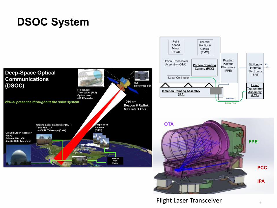
Deep-Space Optical Communications(DSOC)
Virtual presence throughout the solar system
..
Flight Laser Transceiver (FLT)Optical Head4W, 22 cm dia.
FLTElectronics Box
1064 nmBeacon & UplinkMax rate 1 kb/s
Ground Laser Receiver (GLR)Palomar Mtn., CA5m-dia. Hale Telescope
Ground Laser Transmitter (GLT)Table Mtn., CA1m-OCTL Telescope (5 kW)
Optical CommOps Ctr.
MissionOps
Center
Optical TransceiverAssembly (OTA)
PointAheadMirror(PAM)
Photon CountingCamera (PCC)
ThermalMonitor &Control(TMC)
Laser Collimator
LaserTransmitterAssembly
(LTA)Isolation Pointing Assembly
(IPA)
FloatingPlatform
Electronics(FPE)
StationaryPlatfrom
Electronics(SPE)
Optical Fiber
Data/Pwr
Ext.I/F
OTA
FPE
PCC
IPA
Flight Laser Transceiver 4
Deep Space Optical Communication Technology Challenges
• Deep Space Optical Communications are different from near earth communications– One way light times are minutes rather than seconds
Distances are large enough that signals are photon limited–
• Communication Scenario– Uplink signal communicates with DSOC flight terminal by dead reckoning,
providing a beacon and uplink data• Uplink signal at the spacecraft is photon limited
– The flight system tracks the beacon, and using spacecraft ephemeris and attitude information calculates the point ahead angle required for downlink
The downlink beam is directed to where Earth will be
The downlink beacon is photon limited on arrival at Earth
The sun is often very near the field of regard of the Flight Terminal
–
–
–
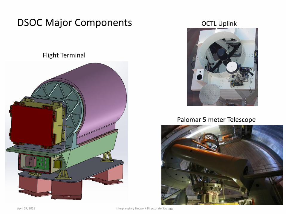
DSOC Major Components
Flight Terminal
OCTL Uplink
Palomar 5 meter Telescope
April 27, 2015 Interplanetary Network Directorate Strategy
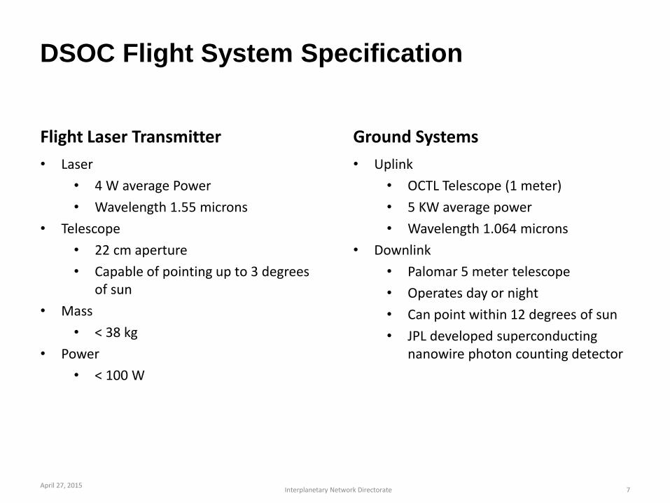
DSOC Flight System Specification
Flight Laser Transmitter
• Laser
• 4 W average Power
Wavelength 1.55 microns•
• Telescope
• 22 cm aperture
Capable of pointing up to 3 degrees of sun
•
• Mass
• < 38 kg
• Power
• < 100 W
Ground Systems
• Uplink
• OCTL Telescope (1 meter)
5 KW average power
Wavelength 1.064 microns
•
•
• Downlink
• Palomar 5 meter telescope
Operates day or night
Can point within 12 degrees of sun
JPL developed superconducting nanowire photon counting detector
•
•
•
April 27, 2015Interplanetary Network Directorate 7
April 27, 2015Interplanetary Network Directorate
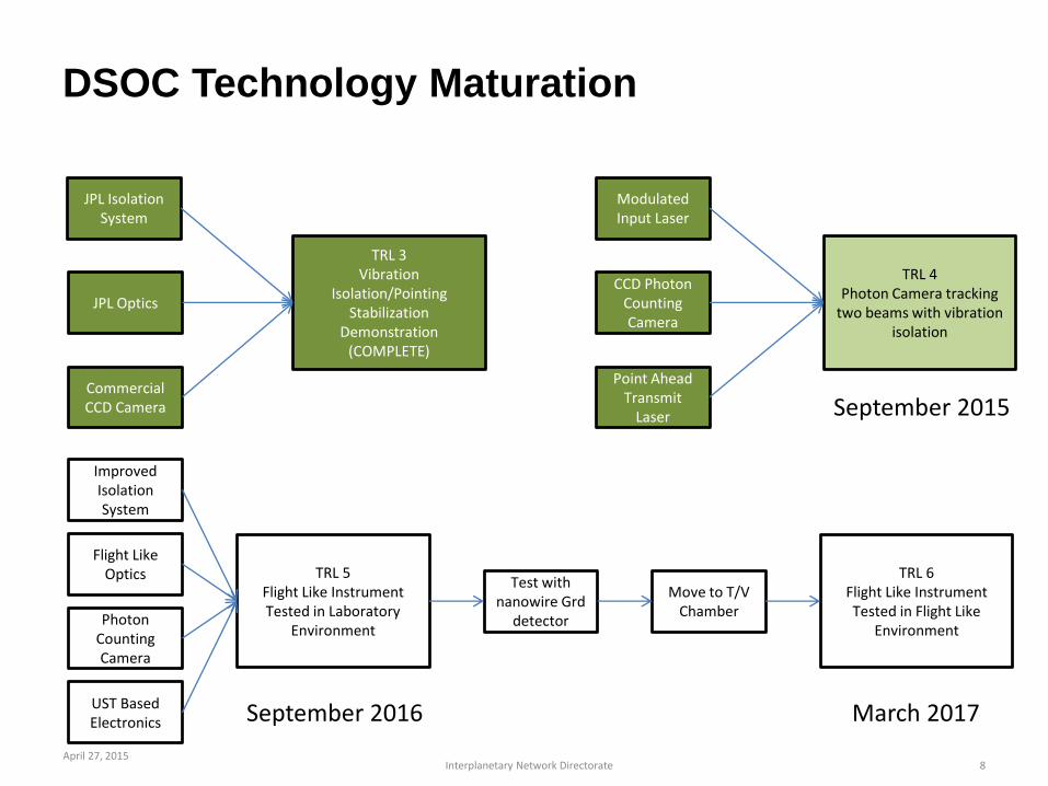
DSOC Technology Maturation
JPL IsolationSystem
JPL Optics
Commercial CCD Camera
TRL 3Vibration
Isolation/Pointing Stabilization
Demonstration(COMPLETE)
Modulated Input Laser
CCD Photon Counting Camera
Point Ahead Transmit
Laser
TRL 4Photon Camera tracking
two beams with vibration isolation
September 2015
Improved Isolation System
Flight Like Optics
Photon Counting Camera
UST Based Electronics
TRL 5Flight Like Instrument Tested in Laboratory
Environment
September 2016
Test with nanowire Grd
detector
Move to T/V Chamber
TRL 6Flight Like Instrument Tested in Flight Like
Environment
March 2017
8
•
•
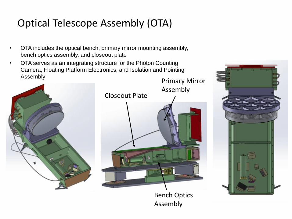
Optical Telescope Assembly (OTA)
OTA includes the optical bench, primary mirror mounting assembly,
bench optics assembly, and closeout plate
OTA serves as an integrating structure for the Photon Counting
Camera, Floating Platform Electronics, and Isolation and Pointing
AssemblyPrimary Mirror Assembly
Bench Optics Assembly
Closeout Plate
•
•
•
•
•
•
April 27, 2015Interplanetary Network Directorate
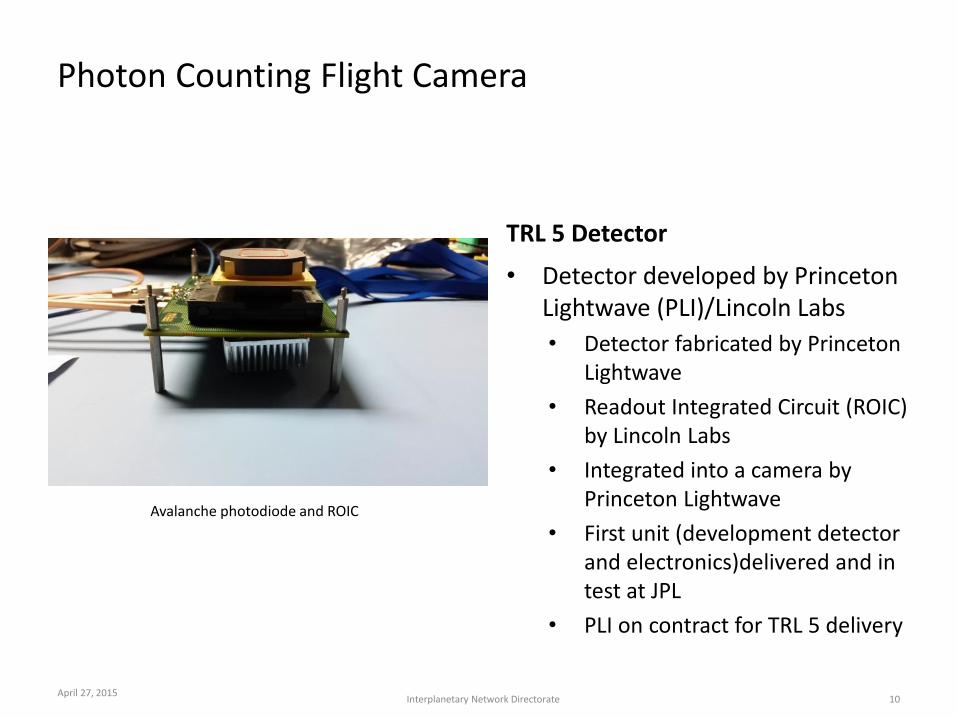
Photon Counting Flight Camera
Avalanche photodiode and ROIC
TRL 5 Detector
Detector developed by Princeton Lightwave (PLI)/Lincoln Labs
Detector fabricated by Princeton Lightwave
Readout Integrated Circuit (ROIC) by Lincoln Labs
Integrated into a camera by Princeton Lightwave
First unit (development detector and electronics)delivered and in test at JPL
PLI on contract for TRL 5 delivery
10
•
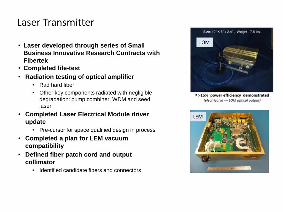
Laser Transmitter
Laser developed through series of Small
Business Innovative Research Contracts with
Fibertek
Completed life-test
Radiation testing of optical amplifier
•
•
• Rad hard fiber
Other key components radiated with negligible
degradation: pump combiner, WDM and seed
laser
•
• Completed Laser Electrical Module driver
update
• Pre-cursor for space qualified design in process
• Completed a plan for LEM vacuum
compatibility
Defined fiber patch cord and output
collimator
•
• Identified candidate fibers and connectors
LEM
LOM
LEM
•
•
•
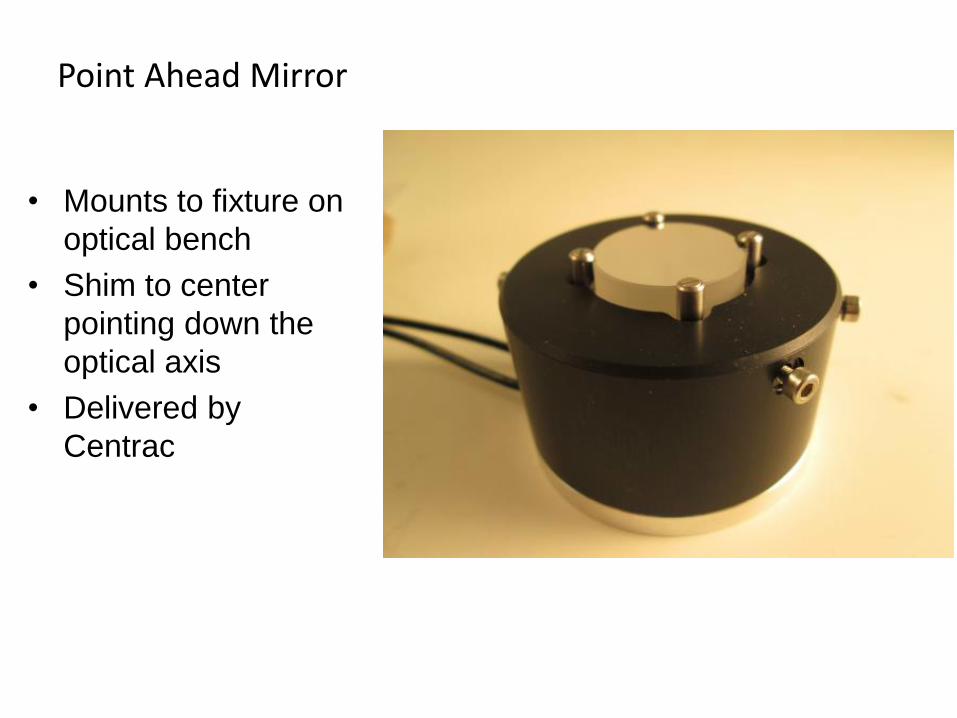
Point Ahead Mirror
Mounts to fixture on
optical bench
Shim to center
pointing down the
optical axis
Delivered by
Centrac
•
•
•
•
April 27, 2015Interplanetary Network Directorate
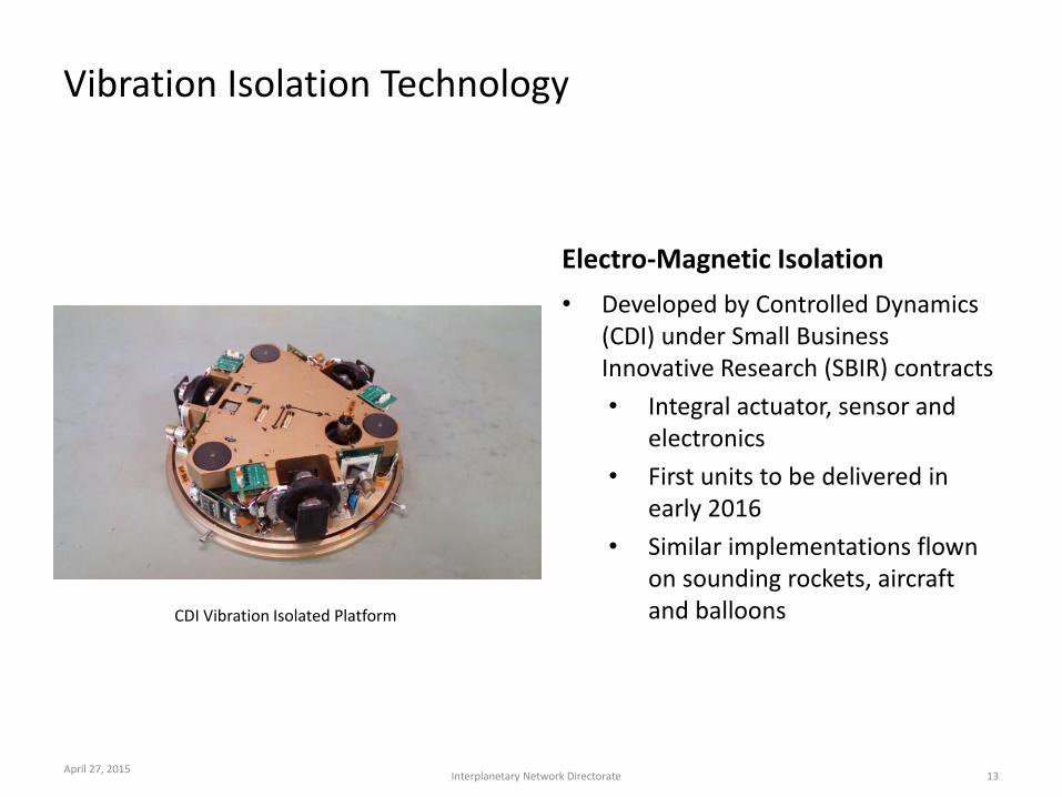
Vibration Isolation Technology
CDI Vibration Isolated Platform
Electro-Magnetic Isolation
Developed by Controlled Dynamics (CDI) under Small Business Innovative Research (SBIR) contracts
Integral actuator, sensor and electronics
First units to be delivered in early 2016
Similar implementations flown on sounding rockets, aircraft and balloons
13
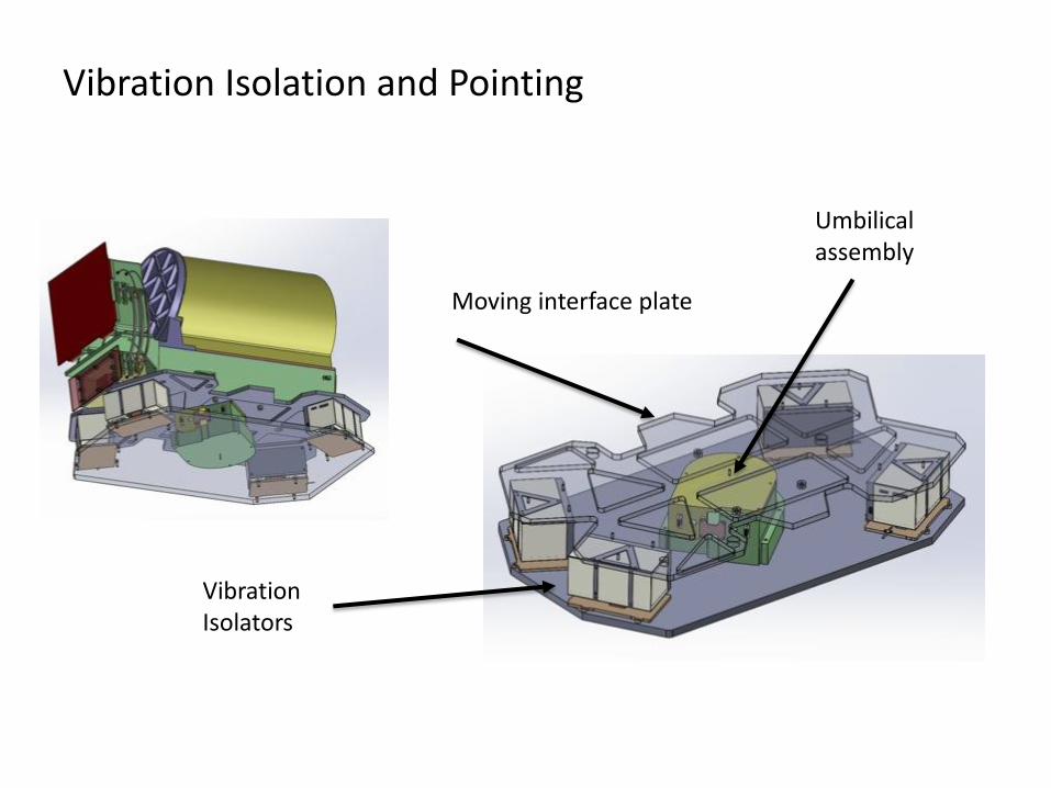
Vibration Isolation and Pointing
Moving interface plate
Umbilical assembly
Vibration Isolators
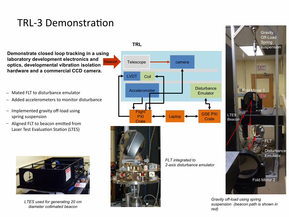
TRL-3 Demonstration
Demonstrate closed loop tracking in a using laboratory development electronics and optics, developmental vibration isolation hardware and a commercial CCD camera.
TRL
cameraTelescope
Coil
Disturbance EmulatorAccelerometer
LaptopFlight PXI
Crate
GSE PXI Crate
LVDT
Mated FLT to disturbance emulatorAdded accelerometers to monitor disturbance
Implemented gravity off-load usingspring suspensionAligned FLT to beacon emitted from Laser Test Evaluation Station (LTES)
LTES used for generating 20 cm diameter collimated beacon
FLT integrated to 2-axis disturbance emulator
onBeac
_
__
_
Gravity Off-LoadSpringsuspension
Fold Mirror 1
LTES Beacon
FLT+DisturbanceEmulator
Fold Mirror 2
Gravity off-load using springsuspension (beacon path is shown in red)
•
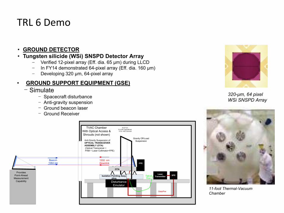
TRL 6 Demo
GROUND DETECTORTungsten silicide (WSi) SNSPD Detector Array•
Verified 12-pixel array (Eff. dia. 65 μm) during LLCDIn FY14 demonstrated 64-pixel array (Eff. dia. 160 μm)Developing 320 μm, 64-pixel array
• GROUND SUPPORT EQUIPMENT (GSE)Simulate
Spacecraft disturbanceAnti-gravity suspensionGround beacon laserGround Receiver
DisturbanceEmulator
Beacon1064 nm
1550 nmDownlink
LaserTransmitter
Data/Pwr
Gravity Off-LoadSuspension
ProvidesPoint-Ahead
MeasurementCapability
Anti-Gravity Suspension ofOPTICAL TRANSCEIVERASSEMBLY (OTA)(Optical Transceiver +PAM + Laser Collimator+FPE)
TVAC ChamberWith Optical Access &Shrouds (not shown)
OpticalFiber
1E-6 Torr0 to 25C Operational-15 to +45C Survival
SPE
OTA
Isolation Pointing Assy.(IPA)
FPE
__
_
____
_320-μm, 64 pixelWSi SNSPD Array
11-foot Thermal-VacuumChamber
•
•
•
•
•
•
April 27, 2015Interplanetary Network Directorate
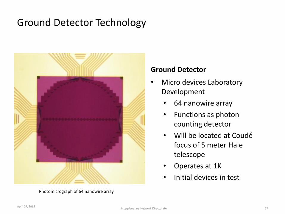
Ground Detector Technology
Photomicrograph of 64 nanowire array
Ground Detector
Micro devices Laboratory Development
64 nanowire array
Functions as photon counting detector
Will be located at Coudé focus of 5 meter Hale telescope
Operates at 1K
Initial devices in test
17
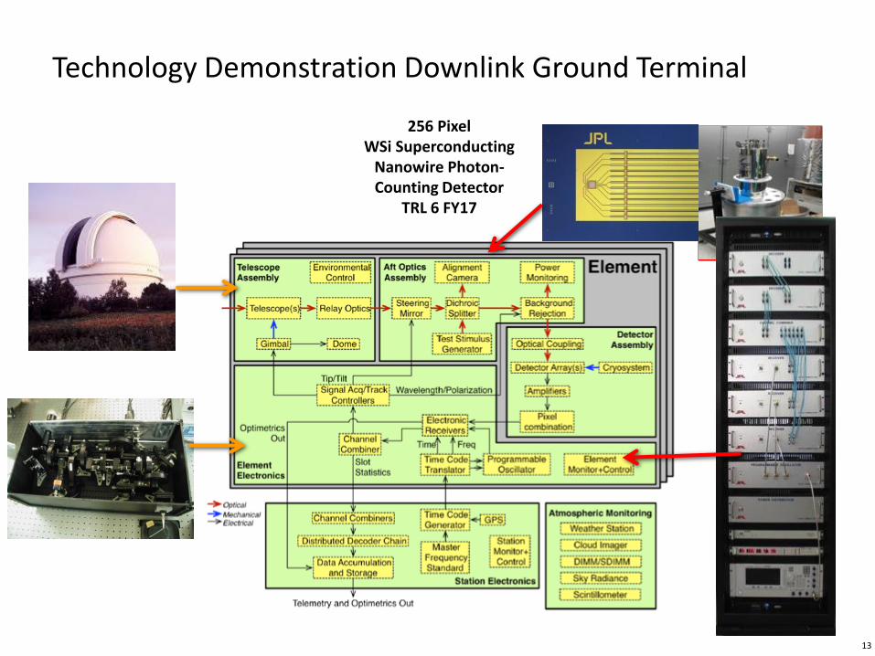
Technology Demonstration Downlink Ground Terminal
256 PixelWSi Superconducting
Nanowire Photon-Counting Detector
TRL 6 FY17
13
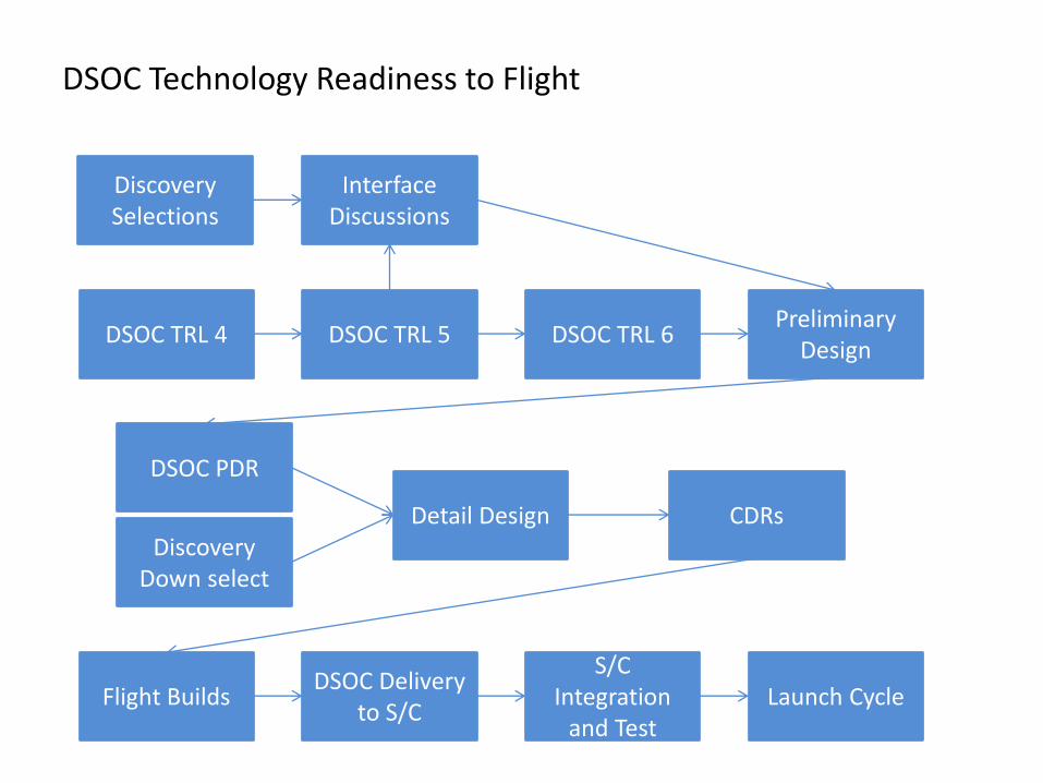
DSOC Technology Readiness to Flight
Discovery Selections
Interface Discussions
DSOC TRL 4 DSOC TRL 5 DSOC TRL 6Preliminary
Design
DSOC PDR
Discovery Down select
Detail Design CDRs
Flight BuildsDSOC Delivery
to S/C
S/C Integration
and TestLaunch Cycle
•
•
•
•
Summary
DSOC Technology Development Progress is compatible with the Discovery Program Schedule
Moving to complete TRL 3 – 6 sequence while making hardware and software designs as flight like as possible
Ensuring that the Flight and Ground Systems remain closely coupled and compatible
Identified paths for technology development to flight and ground operational readiness