Embed Size (px)
Citation preview
Vol.:(0123456789)1 3
Rock Mechanics and Rock Engineering (2019) 52:1417–1446 https://doi.org/10.1007/s00603-019-01799-4
ORIGINAL PAPER
Deep Mining: A Rock Engineering Challenge
Horst Wagner1
Received: 3 September 2018 / Accepted: 24 March 2019 / Published online: 13 April 2019 © The Author(s) 2019
AbstractIncreasing demand for metals caused by global economic growth and exploitation of shallow mineral deposits forces mineral extraction to go deeper. A direct consequence of this development is an increase in rock pressure-related mining problems. The role of rock engineering in the design and operation of deep mines is discussed in detail. Critical issues are the rock fracturing around mining excavations, the support and control of the fractured rock, and the rock mechanics design of mine infrastructure and extraction (stoping) systems. Progress of the science of rock mechanics in the areas related to these issues is highlighted and critically examined. Specific areas are the prediction and assessment of the mechanical properties of rock mass, the mechanics of controlling fractured rock around deep mining excavations and the resulting demands on sup-port systems. Rock engineering aspects of stoping systems and the regional stress changes resulting from the extraction of large mineral bodies are discussed in detail. The progress in design concepts for open stopes and stopes with caving of the roof strata is illustrated. It is shown that the stress environment in deep mines does not favour the highly productive caving systems of stoping. The value of energy-based design concepts for very deep mines exploiting tabular mineral deposits is shown. Despite the considerable progress that has been made in the science of rock mechanics since the 1950s, progress in applying this knowledge to solve rock pressure problems in deep mines has been rather slow. The tools are available. What is needed is the development of robust design criteria for mine infrastructure, excavations and support systems for dynamic and changing stress environments. The second critical issue is the lack of highly qualified rock engineering personnel on the mines. This has been recognized by the European mining industry through supporting a continued education programme in rock engineering for deep mines.
Keywords Rock mechanics principles · Rock engineering methods · Mine design · Design criteria · Support principles · Support methods
List of Symbols
Basic unitsm Metrekg Kilogramme (mass)s Second
Derived unitsm² Square metrem³ Cubic metrem/s Velocitykg/m³ DensityN Newton (force), 1 N = 1kg m/s2
Pa Pascal (Pa) pressure or stress, 1Pa = 1N/m²
J Joule (energy or work), 1J = 1N*1mW Watt (power), 1W = 1J/s
Symbols of quantitiesF ForceL LengthM MassT TimeD Dimension-less
Spaceα, β, γ, δ, θ,φ Angle (plane angle) (D)l Length (L)b Width (L)h Height (L)d Thickness (L)r Radius (L)ϕ, d Diameter (L)
* Horst Wagner [email protected]
1 Montanuniversitaet Leoben, Erzherzog-Johann-Str. 3, 8700 Leoben, Austria
1418 H. Wagner
1 3
A Area (L2)V Volume (L3)
Mechanics: Kinematicsv, c velocity (LT−1)a Acceleration (LT−2)g Gravitational acceleration (LT−2)
Statics and dynamicsm Mass (M)ρ Density (ML−3)F Force (P)W Weight, dead weight (F)γ Unit weight (FL−3)W Work, energy (FL)
Applied mechanicsp Pressure (FL−2)σ Normal stress (FL−2)σx, σy, σz Stress components in rectangular coordi-
nates (FL–2)σr, σθ,σz Stress components in cylindrical coordi-
nates (FL−2)σ1, σ2, σ3 Principal stresses (FL−2)p Hydrostatic stress, pressure (FL−2)pz Primary vertical stress (FL−2)px, py Primary horizontal stresses (FL−2)k Ratio of primary horizontal to vertical
stresses (D)ks Stiffness (FL−1)
Rock and rock mass propertiesν Poisson’s ratio (D)E Young’s modulus, modulus of elasticity E
= σ/ε (FL−2)σc Uniaxial compressive strength of rock
(FL−2)σcrm Uniaxial compressive strength of rock
mass (FL−2)RQD Rock quality designator Deere (1968) (D)RMR Rock mass rating Bieniawski (1976, 1978,
1989) (D)MRMR Mining rock mass rating Laubscher (1990,
1994)DGSI Geological strength index Hoek et al.
(2002, 2013) (D)Q Rock mass quality Barton (1974, 2002)
(D)m Parameter in Hoek- Brown generalized
rock strength criterion describing effect of rock type on strength increase with con-finement Hoek-Brown (1980) (D)
s Parameter in Hoek- Brown generalized rock strength criterion describing effect of rock disintegration on rock strength (D)
Mining: Support systemsCMC Continuously mechanically coupled sup-
port tendon (fully grouted tendon)CFC Continuously frictionally coupled support
tendon (friction bolts)DMFC Discretely mechanically or frictionally
coupled support tendons (mechanical end anchors, D-Bolt, cone-bolt)
Pillar systemsw Pillar width (L)weff Effective pillar width used to convert
irregular shaped pillars into square pillars (L)
l Pillar length (L)h Pillar height (L)R w/h ratio of pillar (D)Rm Minimum w/h ratio of pillar (D)Ro Width/height ratio at which pillar is con-
sidered to become squat (D)a, b Exponents to account for size effects on
pillar volume Vp and R0 (D)εs Measure of strength increase once w/h
exceeds R0 (D)LBR Length benefit ratio to account for effect of
l/w ratio on strength of rectangular pillars of different R (D)
b Room width (L)e Extraction ratio (D)Ap Pillar cross sectional area (L2)Cp Pillar circumference (L)Vp Volume of pillar (L3)Dmp Depth of mining panel below surface (L)Wmp Width of mining panel (L)Lmp Length of mining panel (L)σp Average pillar stress (FL−2)σcp Compressive strength of pillar (FL−2)kcp Strength reduction factor to convert rock
strength to pillar material strength (D)c, d Parameters in linear pillar strength for-
mulas to account for effect of R on pillar strength σcp (D)
α, β Exponents in power laws to determine pil-lar strength σcp (D)
p Uniform load acting on pillar system (FL−2)
ksp Pillar stiffness (FL−1)dLS Constant describing deformation charac-
teristics of loading system (D)dP Constant describing deformation behavior
of pillar (D)Δz Strata deflection (L)P Pillar load (F)

1419Deep Mining: A Rock Engineering Challenge
1 3
qb Bearing capacity of weak roof and floor rock formations (FL−2)
ϕ Friction angle of loaded mediumΝc, Νq, Nγ Bearing capacity factors (D)FS Safety factor (D)
Other mining systemsRhyd Representative excavation parameter,
“hydraulic radius” (L)Αs Area of excavation wall (L2)Cs Circumference of excavation wall (L)Nʹ Stability number (D)Qʹ Modified Q tunneling index after Barton
et al. (1974) (D)A Rock stress factor–Mathews (1991) (D)B Joint orientation adjustment factor
Mathews (1991) (D)C Gravity adjustment factor–Mathews (1991)
(D)l Half span of tabular excavation (L)lc Critical half span (half span at which total
closure occurs in mined out area (L)ERR Energy release rate (J/m2 or J/m3) (FL−1,
FL3)ESS Excess shear stress (FL−2)RCF Rockwall conditions factor (D)kc Strength reduction factor to account for
effect of discontinuities on rock mass strength (D)
Numerical methods and modelsFDM Finite difference methodFEM Finite element methodFVM Finite volume methodΒΕΜ Boundary element methodDEM Discrete element methodDFN Discrete fracture networkDDA Discontinuous deformation analysisFEM/DEM Combined finite element-discrete element
methodΒΕΜ/FEM Combined finite element-boundary ele-
ment methodCHSF Cohesion softening friction hardening
material model
1 Introduction
The editors of the Rock Mechanics & Rock Engineering jour-nal are to be congratulated for organizing a special issue on rock mechanics and rock engineering in mining. This raises the question whether there is a need for a special issue on mining rock mechanics and rock engineering and if so what are the differences to rock mechanics and rock engineering
in civil underground construction. A further point that needs clarification is increased emphasis on rock engineering com-pared to rock mechanics. Let us look at the second issue first. A widely accepted definition of rock mechanics is that first proposed by the US National Committee on Rock Mechanics in 1964, and subsequently modified in 1974:
Rock mechanics is the theoretical and applied science of the mechanical behavior of rock and rock masses; it is that branch of mechanics concerned with the response of rock and rock masses to the force fields in their physical environment. Brady and Brown (2004).
Rock engineering is seen as the application of rock mechanics principles in the design, construction and sup-port of underground structures. Within the context of this contribution, the discussion will be confined to the design and support of extraction (stoping) and service excavations in mines. Rock excavation by means of drilling and blasting and mechanical means will not be covered with the excep-tion of caving of rock, i.e. rock breakage due to the effects of gravity.
2 Differences Between Mining and Subsurface Rock Engineering
Before discussing the main differences between mining and subsurface rock engineering, it is necessary to understand the purpose of the two branches of engineering. The sole purpose of mining is to provide society with those miner-als and mineral products which are required for energy pro-duction, the provision of materials for the manufacturing, chemical, food and pharmaceutical industries and the con-struction industry. The main purpose of subsurface activities is the utilization of the underground space for establishing infrastructure-required public utilities for transport, water and electricity distribution, the use of underground space in urban areas for storage of goods, parking of vehicles, librar-ies, sporting facilities, etc. and military installations.
There are a number of differences between mining and other subsurface construction activities which have a direct or indirect influence on rock engineering, Wagner (2015). The more important of these are summarized in Table 1.
From Table 1, it is evident that there are fundamental differences between the two sector subsurface activities. In the case of mining, the purpose of creating under-ground excavations is to extract the minerals needed by society. In the case of civil subsurface structures, the purpose is to provide the infrastructure required by mod-ern industrial society. Other important differences which have an influence on the rock engineering approach are the areas of ownership and financing. Since most mining companies are private sector enterprises, their financial

1420 H. Wagner
1 3
success depends on the cost of operation and the revenue received from the sale of minerals. In the development stage of a new mine, the costly infrastructure required to prepare the mineral deposit for extraction has to be established. At the stage of mine development, no income from mineral sales is available to finance the infrastruc-ture work. For this reason, the exploration of the geologi-cal situation is often confined to the mineral deposit and very little if any geotechnical information is collected to assist the mine planer. This results in a high design risk which to some extent can be counteracted by flex-ible mine design. Since the design and development of the underground infrastructure is usually carried out by the mining company changes can be implemented read-ily and there are no legal and contractual implications. In the case of civil subsurface construction work, the situ-ation is quite different as there are a number of different organizations involved, namely the owner, the engineer-ing consulting company and the contracting company. Any change in plan has financial and legal implications. For this reason, the degree of site and geological explora-tion tends to be much greater than is the case of mining. This is facilitated by the public funding situation. Another important difference is that civil underground structures are often used by and open to the public, whereas mining excavations are not open to the public. This has implica-tions on design safety and excavation support design.
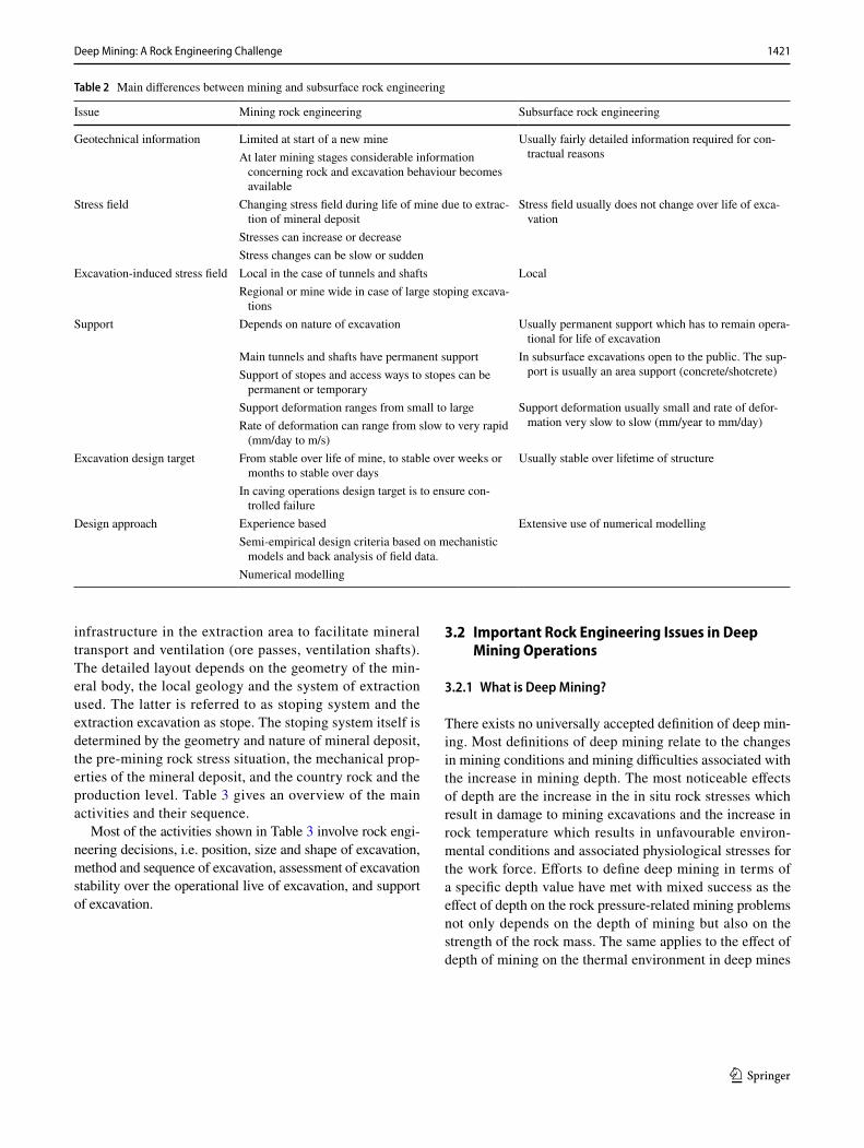
Table 2 summarizes the main differences between mining and subsurface rock engineering. It supports the notion why it is justified to treat mining and subsurface rock excavation and support as two different branches of rock engineering.
3 Mining and Rock Engineering
3.1 General
The main objective of mining is to provide society with the mineral raw materials required by the building indus-try, the energy industry, the manufacturing and chemical industry, the agricultural sector and the transport and com-munication sector. The source of mineral raw materials is the mineral deposit. Mineral deposits are anomalies in the earth crust where physical, chemical, hydrological and biological processes have resulted in a concentration of valuable mineral matter. Mineral deposits are limited in size and number, and constitute a valuable and in most instances non-renewable resource. The locality, size, shape and mineral concentration of a deposit and its geologi-cal and geotechnical environment is determined by nature and is outside human control. This severely constrains the degree of freedom of the rock engineering design of mines.
Once a mineral deposit has been identified by explo-ration and assessed as being economically viable, the mining process commences. It comprises the develop-ment of necessary infrastructure to reach and prepare the mineral body for extraction, the selection of extraction method, extraction of mineral, and transport of mineral. In the case of deep mines, this usually requires the sinking and equipping of shafts, the development of mine tun-nels from the shaft to the vicinity of the deposit (primary development), the development of mine tunnels close to or inside the mineral deposit to prepare it for extraction (secondary development) and the development of vertical
Table 1 Differences between mining and civil subsurface operations and activities
Mining Subsurface construction
Purpose To supply society with minerals required by the construc-tion, manufacturing and chemical industry, energy gen-eration, food production, etc. The purpose of the mining excavations is to gain access to and to extract the mineral deposits
Provision of subsurface structures needed by society for transport, distribution of water electricity, gas, storage, urban infrastructure, military purposes, etc
Owner Mostly private sector companies Mainly public sector organizations, utilities (transport, elec-tricity, gas, water, etc.)
Financing Private sector funding, revenue received from sale of min-erals and mineral products
Public sector financing, utility financing
Design organization Mining company or consulting company Engineering consulting companyConstruction Mining company, construction companies (shaft sinking) Construction company, group of companiesSupervision Mining company, mine owner Engineering company, utility personnelOperation Mining company Utility company (railways, water board, electricity company,
etc.)User of structures Mining personnel Employees of utility company and general public
1421Deep Mining: A Rock Engineering Challenge
1 3
infrastructure in the extraction area to facilitate mineral transport and ventilation (ore passes, ventilation shafts). The detailed layout depends on the geometry of the min-eral body, the local geology and the system of extraction used. The latter is referred to as stoping system and the extraction excavation as stope. The stoping system itself is determined by the geometry and nature of mineral deposit, the pre-mining rock stress situation, the mechanical prop-erties of the mineral deposit, and the country rock and the production level. Table 3 gives an overview of the main activities and their sequence.
Most of the activities shown in Table 3 involve rock engi-neering decisions, i.e. position, size and shape of excavation, method and sequence of excavation, assessment of excavation stability over the operational live of excavation, and support of excavation.
3.2 Important Rock Engineering Issues in Deep Mining Operations
3.2.1 What is Deep Mining?
There exists no universally accepted definition of deep min-ing. Most definitions of deep mining relate to the changes in mining conditions and mining difficulties associated with the increase in mining depth. The most noticeable effects of depth are the increase in the in situ rock stresses which result in damage to mining excavations and the increase in rock temperature which results in unfavourable environ-mental conditions and associated physiological stresses for the work force. Efforts to define deep mining in terms of a specific depth value have met with mixed success as the effect of depth on the rock pressure-related mining problems not only depends on the depth of mining but also on the strength of the rock mass. The same applies to the effect of depth of mining on the thermal environment in deep mines
Table 2 Main differences between mining and subsurface rock engineering
Issue Mining rock engineering Subsurface rock engineering
Geotechnical information Limited at start of a new mine Usually fairly detailed information required for con-tractual reasonsAt later mining stages considerable information
concerning rock and excavation behaviour becomes available
Stress field Changing stress field during life of mine due to extrac-tion of mineral deposit
Stress field usually does not change over life of exca-vation
Stresses can increase or decreaseStress changes can be slow or sudden
Excavation-induced stress field Local in the case of tunnels and shafts LocalRegional or mine wide in case of large stoping excava-
tionsSupport Depends on nature of excavation Usually permanent support which has to remain opera-
tional for life of excavationMain tunnels and shafts have permanent support In subsurface excavations open to the public. The sup-
port is usually an area support (concrete/shotcrete)Support of stopes and access ways to stopes can be permanent or temporary
Support deformation ranges from small to large Support deformation usually small and rate of defor-mation very slow to slow (mm/year to mm/day)Rate of deformation can range from slow to very rapid
(mm/day to m/s)Excavation design target From stable over life of mine, to stable over weeks or
months to stable over daysUsually stable over lifetime of structure
In caving operations design target is to ensure con-trolled failure
Design approach Experience based Extensive use of numerical modellingSemi-empirical design criteria based on mechanistic
models and back analysis of field data.Numerical modelling
1422 H. Wagner
1 3
which depends on the thermal properties of the rock mass. To illustrate these points, the effects of depth on mining conditions in “deep” coal and gold mines are compared. At a depth of 1000 m below surface, the vertical in situ rock stresses are very similar in the two mining situations, namely about 25 MPa in the case of the coal mines and 27 MPa in the case of the gold mines. However, due to the very much weaker rock formations found in coal mines, the rock pres-sure-related problems in the coal mines tend to be much more severe than those experienced by gold mines at the same mining depths. The thermal problems in the two min-ing industries are also very different because of the different thermal properties of the rock formations. In the case of the geologically much younger coal deposits, the temperature increase with depth is about 3 °C/100 m depth, whereas in the case of the 3.500-million-year-old gold mining deposits in Southern Africa the rock temperature increase per 100 m depth is only about 1 °C. At the same mining depths, the virgin rock temperatures in the coal mines are, therefore, three times higher than those found in gold mines. These examples illustrate and explain the difficulties encountered in defining deep mining. A more appropriate approach from a rock pressure point of view is to define “deep mines” in terms of a rock stress to rock strength ratio. In the case of the gold mines, the use was made of the concept of a criti-cal field stress which corresponded to 0.4 of the uniaxial compressive strength of the rock. For rocks with a strength of 150 MPa, which is an average value for rocks found in gold mining regions in Southern Africa, this would equate to 60 MPa and correspond to a depth of about 2000 m, Wag-ner and Salamon (1975). In the case of the coal mines, the strength values range from about 30 MPa for coal and weak shale to 80 MPa for sandstone. These strength values cor-respond to critical stress values ranging from 12 to 32 MPa and depth values of about 500 m and 1200 m, respectively. In the case of the heat problems in deep mines, the depth at which the virgin rock temperature exceeds 30 °C would appear to be bench mark value as at such rock temperatures measures would have to be taken to cool the ventilating air to prevent heat stress problems. One exemption is the salt mines where the acceptable air temperatures can be somewhat higher because of the very low humidity of the ventilating air, Wagner (2010). For hard rock mines, typi-cal deep mining problems are likely to be encountered at depths below 1500 m. In the case of coal mining, it seems appropriate to speak of deep mines at depths greater than 750 m below surface.
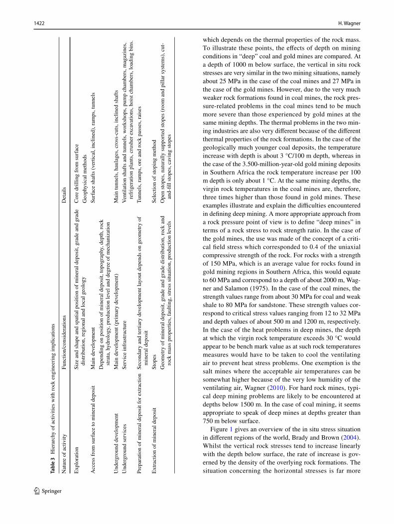
Figure 1 gives an overview of the in situ stress situation in different regions of the world, Brady and Brown (2004). Whilst the vertical rock stresses tend to increase linearly with the depth below surface, the rate of increase is gov-erned by the density of the overlying rock formations. The situation concerning the horizontal stresses is far more Ta
ble
3 H
iera
rchy
of a
ctiv
ities
with
rock
eng
inee
ring
impl
icat
ions
Nat
ure
of a
ctiv
ityFu
nctio
n/co
nsid
erat
ions
Det
ails
Expl
orat
ion
Size
and
shap
e an
d sp
atia
l pos
ition
of m
iner
al d
epos
it, g
rade
and
gra
de
distr
ibut
ion,
regi
onal
and
loca
l geo
logy
Cor
e dr
illin
g fro
m su
rface
Geo
phys
ical
met
hods
Acc
ess f
rom
surfa
ce to
min
eral
dep
osit
Mai
n de
velo
pmen
tSu
rface
shaf
ts (v
ertic
al, i
nclin
ed),
ram
ps, t
unne
lsD
epen
ding
on
posi
tion
of m
iner
al d
epos
it, to
pogr
aphy
, dep
th, r
ock
strat
a, h
ydro
logy
, pro
duct
ion
leve
l and
deg
ree
of m
echa
niza
tion
Und
ergr
ound
dev
elop
men
tM
ain
deve
lopm
ent (
prim
ary
deve
lopm
ent)
Mai
n tu
nnel
s, ha
ulag
es, c
ross
-cut
s, in
clin
ed sh
afts
Und
ergr
ound
serv
ices
Serv
ice
infr
astru
ctur
eVe
ntila
tion
shaf
ts a
nd tu
nnel
s, w
orks
hops
, pum
p ch
ambe
rs, m
agaz
ines
, re
frig
erat
ion
plan
ts, c
rush
er e
xcav
atio
ns, h
oist
cham
bers
, loa
ding
bin
s.Pr
epar
atio
n of
min
eral
dep
osit
for e
xtra
ctio
nSe
cond
ary
and
terti
ary
deve
lopm
ent l
ayou
t dep
ends
on
geom
etry
of
min
eral
dep
osit
Tunn
els,
ram
ps, o
re a
nd ro
ck p
asse
s, ra
ises
Extra
ctio
n of
min
eral
dep
osit
Stop
esSe
lect
ion
of st
opin
g m
etho
dG
eom
etry
of m
iner
al d
epos
it, g
rade
and
gra
de d
istrib
utio
n, ro
ck a
nd
rock
mas
s pro
perti
es, f
aulti
ng, s
tress
situ
atio
n, p
rodu
ctio
n le
vels
Ope
n sto
pes,
natu
rally
supp
orte
d sto
pes (
room
and
pill
ar sy
stem
s), c
ut-
and-
fill s
tope
s, ca
ving
stop
es

1423Deep Mining: A Rock Engineering Challenge
1 3
complex. The ratio k expresses the horizontal stress, px and py, in terms of the primary vertical stress, pz. At shallow to moderate depths, 0 m < D < 1000 m, the horizontal stresses can vary in a wide range, 0.3 < k < 3.5. At depths greater than 1000 m, the horizontal stress in the earth crust tends to be equal or smaller than the vertical stresses, 1 > k > 0.3. A comprehensive overview of the topic of horizontal stresses in the earth crust is provided by Zang and Stephansson (2010). Numerous models have been proposed explaining mechanisms for the wide spread of horizontal stress values in the earth crust (McCutchen 1988; Amadei et al. 1988; Sheorey 1994). The uncertainty concerning magnitude of the pre-mining horizontal stresses constitutes a serious problem in the rock mechanics planning of new mines.
3.2.2 Mine Infrastructure
From a rock engineering point of view, the mine infra-structure comprises all excavations, i.e. shafts, raises, ore and rock passes, mine tunnels and underground chambers of various size and geometry, which are necessary to gain access to the mineral body and to prepare the mineral body for extraction, to transport men, equipment and material to and from the extraction area, to transport the mineral and waste rock from the extraction area to the surface, to ensure supply of the operating areas with energy and air, and to pump water from underground. In addition excava-tions are required for necessary services such as pump chambers, refrigeration plants, hoist chambers, under-ground workshops and store rooms, and refuge chambers. Most of these excavations have to remain operational
throughout the life of mine but at least throughout the operational life of mining sections. To ensure the stabil-ity of these excavations, careful planning is essential tak-ing into considerations the stress changes throughout the operational life of the infrastructure.
Important rock engineering decisions are:Design of mine infrastructure for life of mine operation
Rock engineering design and support of shaft systemsProtection of shaft systems from the effects of stoping activitiesDesign of shaft pillarsSiting and support of primary infrastructure develop-mentSiting and support of secondary infrastructure develop-ment
Development of tertiary infrastructure in the stoping area.
This infrastructure is subjected to significant stress changes resulting from the stoping activities. Seismic loading is not uncommon and has to be allowed for by the support system. Operational life time of tertiary infrastructure is often short.
3.2.3 Selection of Stoping System from a Rock Engineering Point of View
The central activity of mining is the extraction of the min-eral body. Since mineral deposits are anomalies in the earth crust, each deposit has to be treated separately. Notable
Fig. 1 Variation of measured in situ vertical stress, pz, with depth below surface in different mining regions and ratio of measured average hori-zontal stresses to the vertical stress, adopted from Brady and Brown (2004)
1424 H. Wagner
1 3
exceptions are the relatively shallow coal deposits in Aus-tralia, South Africa and the United States of America which have similar geological and rock stress conditions or the deep tabular gold and platinum deposits in South Africa and some of the steeply dipping nickel deposits in Canada. For these deposits, some fairly common extraction systems and design criteria have evolved over time. In the majority of other cases, stoping systems have to be tailored to the local geological and stress conditions.
Critical rock engineering decisions are:
Open stopes:
Size and shape of stope, support of stope walls
Naturally supported stopes (pillars):
Design of pillar systems for hard rock conditionsStope pillarsCrush pillarsBarrier and stabilizing pillar
Back filled stopes:
Type of back fill, percentage back fill
Caving of strata:
Assessment of caving characteristics of rock massSize of stope required to induce cavingBack break and periodic rock pressure situations
3.2.4 Support Systems
The rock stress environment in deep mines is such that rock fracturing around mining excavations often cannot be pre-vented. To ensure the stability of the mine infrastructure and the functionality of the mining excavations, to protect the workforce from rock falls and to facilitate the mining opera-tions, it is necessary to support the mining excavations. In deep mines, excavation support is one of the most important, labour-, material- and resource-intensive activities. Support considerations and decisions have to be made already at the planning stages of mine infrastructure design to avoid unfa-vourable rock pressure situations which necessitate extensive and expensive support measures.
Central issues in the area of mine support are the selec-tion and design of tunnel support systems taking into con-sideration the importance of excavation, its expected service life and stress changes throughout the life time of the excava-tion. In deep mines, support design not only has to consider high quasi-static rock stress conditions but also dynamic loading situations such as encountered in the event of rock bursts in the vicinity of the excavation. In seismically active mines, the ability of support to absorb significant amounts
of energy is an important design and selection criterion to ensure the stability of the excavation. In the case of mine tunnels, complex-integrated support systems are required to ensure overall excavation stability under static and dynamic loading conditions. This is achieved by the yielding support tendons. The support of the fractured rock at the skin of the excavation is provided by flexible boundary or surface sup-port elements which contain the rock fragments in the area between the support tendons, Kaiser et al. (1997)
Important aspects of mine support activities on deep mines are:
development of mine specific criteria for the selection and design of the support system based on the expected stress environment and rock burst hazard over the operational life of excavationestablishment of appropriate support standardsinstallation of support systems and monitoring of support performance.support of stoping excavations
open stopes and pillar systemscaving stopes
lost supportmechanized re-usable supports
3.2.5 Mine Seismicity
A specific feature of deep mines is the occurrence of min-ing-induced tremors. The first structured effort to address this problem was the establishment of the Orphirton Earth Tremor Committee in 1908, Durrheim (2010). Mining-induced seismicity is the result of instabilities in the rock mass which are triggered by the stress changes caused by the mining activities. The magnitude of the seismic event depends on the energy stored in the rock mass in the source area of the event. Mining-induced seismicity ranges in energy from 105 to 109 J. Seismic events radiating more than 104 J can cause considerable damage to mine workings and are referred to as rockbursts, Salamon (1983). Much progress has been made in understanding mining-induced seismicity and in ameliorating the rockburst hazard in deep mines. Mine design concepts based on controlling energy changes caused by mining have been developed and are being applied (Cook 1961; Salamon 1974, 1983; Ryder and Jager 2002). The key to mitigate the rockburst hazard in deep mines is to limit mining-induced energy changes in the rock mass by means of stoping width control, use of backfill in the mined out area and by application of partial extrac-tion systems, COMRO (1988). Particularly critical are min-ing activities in the vicinity of major geological structures such as faults and dykes, Gay et al. (1984). Mine support
1425Deep Mining: A Rock Engineering Challenge
1 3
systems have to be able to absorb large amounts of energy during yielding. The substantial progress that was made in this area is summarized in the excellent textbook by Kaiser et al. (1996).
Mine-wide seismic monitoring systems are state-of-the-art and used routinely on deep mines in Australia, Canada and South Africa, Mendecki (1997). These systems can provide very valuable data concerning seismic activities in mines and the effectiveness of mining strategies. Efforts to predict reliably rockbursts in time and space have so far met with little success.
Important rock engineering decisions on seismically active mines are:
Monitoring of seismic activities
Operation of seismic networksAnalysis of seismic dateReporting of seismic data to production personnelEvaluation of effectiveness of measures taken to reduce seismic hazardIdentification of seismically active areas and structuresPrediction of the effects of mine seismicity on the sur-face and surface structures.
Development of design criteria for mining excavations in seismically active areasDevelopment of mining strategies to alleviate the seismic hazardRegional measures
Methods to control mining-induced energy changesStoping layouts in vicinity of major geological dis-continuitiesStoping sequence
Local measures
Support of seismically active areas.
3.2.6 Surface Subsidence
A consequence of extensive mining activities is the distur-bance of the surface and surface structures. The extent of dam-age depends on the size and shape of mining excavation, the nature of the rock formations affected by mining operations and the type of support employed. Another important factor is the depth of mining. At relatively shallow depth, the stresses are low. This has two consequences, namely rock fracturing around excavations tends to be restricted to low-strength rock formations. The second effect concerns rock wedges in the roof of excavations which can move relatively freely because of lack of confinement due to the low horizontal stresses. As
a result, subsidence is a common problem in many shallow mining situations in low-strength and intensely jointed rock masses. This type of subsidence is known as discontinuous subsidence. As the depth of mining increases the horizontal stresses in the rock mass increase and gravity-driven rock movement is restricted by frictional forces. As a result rock movement above mined out areas becomes more continuous and the pattern of surface subsidence more predictable. Apart from the vertical downward movement of the surface, hori-zontal strains are observed on the surface. These tend to be compressive in the middle of the mined out area and tensile close to the edges of the mined out area and beyond it. The maximum tilt of the surface occurs slightly inside the edge of the extraction area. It was found that strain and tilt on the surface were proportional to the maximum subsidence and inversely proportional to the depth of mining. Since it is the strain and the tilt which cause damage to surface structures, the deleterious effects of mining activities on the surface tend to decrease with the depth of mining, National Coal Board (1975). In the case of mining massive mineral deposits using caving methods, discontinuous subsidence is observed. This results in the formation of fracture systems which extend to the surface. Surface damage can be very severe and subsid-ence can be tens of metres, Henry et al. (2000). In such cases, the surface is no longer suitable for other uses and has to be evacuated. In general, mining-induced surface becomes less of a problem as the depth of mining increases. A specific problem related to the effects of deep mining activities on the surface and surface structures is the mining-induced seismicity which causes ground vibrations. In the case of mine tremors, surface structures can be damaged, Durrheim (2010).
Important issues related to surface subsidence on deep mines are
Prediction of effects of mining activities on the surfaceDesign of extraction systems and excavation sequence to minimize adverse surface effects.Prediction of the effects of mining-induced seismicity on the surface and surface structures.
4 Key Rock Engineering Issues in Deep Mines
From a rock engineering point of view, deep mining is char-acterized by high primary rock stresses which
• often cause failure of the rock surrounding excavations. Depending on the mining and stress situations, and the mechanical properties of rock, the failure process is sta-ble or unstable.
• can prevent or adversely affect the application of stoping systems such as
1426 H. Wagner
1 3
• systems employing support pillars• systems based on caving of the rock strata in the
mined out area
• will require careful regional mining strategies
The key rock engineering issues are
• Numerical modelling of behaviour or rock and rock structures.
• Assessment of rock mass properties and rock stress situ-ation at the planning stage of deep mining projects.
• The understanding of the failure process of rock sur-rounding excavations.
• The control of the failure process.• The support and reinforcement of failed rock.• The rock engineering design of mining systems.
• Extraction (stoping) systems• Mine infrastructure (tunnels, shafts, service excava-
tions)
4.1 Numerical Modelling of Rock Behaviour and Rock Structures
4.1.1 Purpose of Numerical Modelling
The purpose of numerical modelling in rock engineering is to analyze and evaluate the behaviour of rock and rock structures under complex loading conditions, to compare and evaluate different rock engineering designs on a rational basis to select the most appropriate design for specific min-ing situations, to develop semi-empirical mine design cri-teria using the concept of back analysis and to administer
large volumes of rock engineering data. In the past, numeri-cal analysis was confined to problems for which analytical solutions were available and where linear material behav-iour was a realistic approximation of actual rock behaviour. Considerable insight into the behaviour of rock structures could be gained from this simple yet limited approach (Obert and Duvall 1967; Jaeger and Cook 1979; Brady and Brown 2004; Ryder and Jager 2002).
The development of high-speed computer equipment has impacted on all aspects of engineering design and practice, Ryder and Jager (2002). Particularly in the field of rock engi-neering, the availability of high-powered computer equip-ment and a great variety of software products and numeri-cal techniques has opened avenues for the analysis and evaluation of complex rock engineering problems and mine designs. However, to do this effectively and efficiently the rock mechanics engineer is required to discriminate between various software products and numerical techniques. In this regard, it is important to understand the generic differences between the various numerical methods that are commonly employed in rock engineering.
4.1.2 Generic Solution Techniques for Rock Engineering Applications
A great variety of numerical methods for use in rock engi-neering has been developed. A detailed discussion of the various methods goes beyond the scope of this rock mechan-ics review and the reader is referred to comprehensive sum-maries of the state of numerical modelling in rock engineer-ing (Pande et al. 1990; Ryder and Jager 2002, Brady and Brown 2004; Jing and Hudson 2002). The following meth-ods can be distinguished in terms of numerical approach
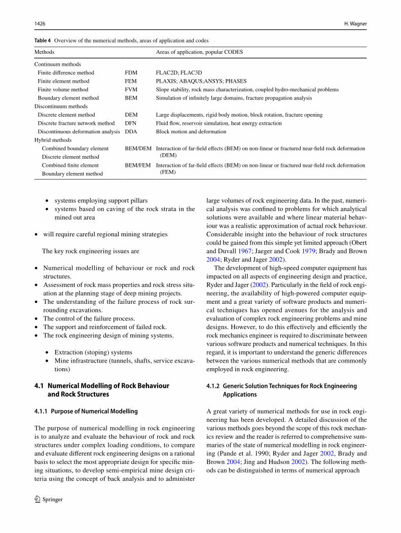
Table 4 Overview of the numerical methods, areas of application and codes
Methods Areas of application, popular CODES
Continuum methods Finite difference method FDM FLAC2D; FLAC3D Finite element method FEM PLAXIS; ABAQUS;ANSYS; PHASES Finite volume method FVM Slope stability, rock mass characterization, coupled hydro-mechanical problems Boundary element method BEM Simulation of infinitely large domains, fracture propagation analysis
Discontinuum methods Discrete element method DEM Large displacements, rigid body motion, block rotation, fracture opening Discrete fracture network method DFN Fluid flow, reservoir simulation, heat energy extraction Discontinuous deformation analysis DDA Block motion and deformation
Hybrid methods Combined boundary element BEM/DEM Interaction of far-field effects (BEM) on non-linear or fractured near-field rock deformation
(DEM) Discrete element method Combined finite element BEM/FEM Interaction of far-field effects (BEM) on non-linear or fractured near-field rock deformation
(FEM) Boundary element method
1427Deep Mining: A Rock Engineering Challenge
1 3
• Analytical methods• Boundary element (BEM) methods• Finite element (FEM) methods• Finite difference (FDM) methods• Distinct element (DEM) methods• Discrete fracture network (DFN)
The numerical methods can be classified into three broad categories continuum, discontinuum and hybrid continuum/discontinuum methods (Nikolic et al. 2016).
As is evident from Table 4, considerable progress was made in the development of numerical models to assist with the solution of rock engineering problems in mines. Most problems encountered with the application of numeri-cal models in rock engineering are the area of defining the primary rock stress environment and the quantification of in situ rock mass properties. Further progress in the applica-tion of numerical methods in rock engineering will depend on progress in these areas.
4.2 Rock and Rock Mass Behaviour
Much progress has been made since the 1950’s in the understanding of the mechanical behaviour of rock and rock masses. In the initial stages, two South African min-ing research organizations, namely the Council for Scien-tific and Industrial Research (CSIR) in Pretoria and the Research Organization of the Chamber of Mines of South Africa (COMRO) in Johannesburg, contributed much to this development. At the CSIR, Denkhaus and Bieniawski (1974) conducted a comprehensive rock testing programme to study the mechanical properties of many different rocks and in particular also the effect sample size on rock strength. A significant step forward in the understanding of the behav-iour of brittle rocks was the development of an ultra-stiff conventional rock testing system by Cook and Hojem (1966) from COMRO which made it possible to study the behaviour strong brittle rocks in the post-failure region. The important finding was that violent failure observed when testing many brittle rocks in compression was not an inherent property of certain rocks but caused by the release of energy stored in the rock testing system. This finding provided an explanation to the observation that most failures observed in mines were of a stable nature, whereas the same rocks tested in the labo-ratory failed violently. This was followed by the develop-ment of servo-controlled rock testing systems which enabled Wawersik and Fairhurst (1970) from Minnesota University to show that there are two different classes of rock, namely those which fail in a stable manner, Class 1, and those which are inherently brittle that is rocks where the stored energy at the point of maximum resistance to deformation is greater than that required to propagate rock failure, Class 2-type rocks. These findings have had far reaching consequences for
the understanding of rock fracturing around deep mine tun-nels in hard rock and the design of pillar systems in mines, Salamon (1974).
In the period 1970 to about 1990, the focus of research in the field of rock and rock mass properties was on study-ing the effects of discontinuities on rock mass behaviour. Leading this work were Bieniawski (1976, 1978, 1989) from the CSIR in Pretoria and later at the Pennsylvania State University and Barton (1974, 2002) from the Norwegian Geotechnical Institute (NGI) in Trondheim. Both research-ers developed empirical procedures to quantify the effects of discontinuities and their properties on rock mass behav-iour. Input parameters are Deere’s Rock Quality Designa-tor (RQD) derived from the analysis of drill cores, number of joint sets, frictional properties of discontinuity surfaces and compressive strength of the rock material. Other factors which are being considered are the effect of water and rock stress on rock mass behaviour. The result of these rock mass classification systems is a discrete number which in the case of Bieniawki’s RMR value ranges from 0 to 100 and in the case of Barton’s Q value from 0.001 to 1000. Bieniawki’s Rock Mass Rating (RMR) system and Barton’s rock quality (Q) system have found wide acceptance to characterize rock masses and to assess rock conditions and support require-ments in tunnels. There is, however, a serious limitation to the use of a discrete rock mass characterization number to describe the rock engineering situation in a tunnel as the orientation of excavation walls with respect to the joint sys-tem and the complex stress environment in tunnels cannot be adequately described by a single number.
Whilst considerable progress was made in the develop-ment of numerical codes to model the behaviour of jointed rock masses, there was a considerable lack of reliable data on important parameters controlling shear behaviour under constant normal load (CNL) and constant normal stiffness (CNS) conditions. Particularly, shear behaviour under con-stant stiffness conditions is of importance in deep mining situations where the dilatation of a sliding block is restricted by surrounding rock mass. With the availability of servo-controlled shear box devices, it is now possible to study shear behaviour of larger test samples under dynamic and hydro-mechanical coupled testing conditions, Konietzky et al. (2012).
In 1980, Hoek and Brown proposed an empirical criterion to estimate the peak strength of intact isotropic rock or an intensely jointed isotropic rock mass
where �1 and �3 are, respectively, the major and minor prin-cipal effective stresses, and m and s are constants which depend on the rock type and the extent to which the rock is fractured before �1 and �3 are applied. The parameter m is a
(1)�1 = �c +
√
m�c�3 + s�2c,

1428 H. Wagner
1 3
measure of the increase in rock strength with confining stress �3 , the parameter s describes the effect of rock disintegration on rock strength. The failure criterion, which is based on a Mohr–Coulomb-type material behaviour, was conceived for use under the confined conditions surrounding underground excavations. It is based on the assumption that rock mass failure is controlled by translation and rotation of individual rock pieces separated by numerous joint surfaces. Failure of the intact rock was assumed not to play a significant role in the overall failure process (Brown and Hood 1999; Hoek 2004; Brown 2011).
In the early stages, RMR was used to estimate the rock mass input parameters m and s. In the mid 1990s, work on a more user-friendly method termed Geological Strength Index (GSI) commenced to replace Bieniawski’s RMR to estimate the rock mass parameters m and s (Hoek 1994; Hoek et al. 1995). Since then, the GSI model has been revised several times and adjusted to different rock types (Marinos and Hoek 2000, 2001; Hoek et al. 2002, 2013). As the generalized Hoek–Brown criterion for estimating rock mass strength has become more widely used, certain prob-lem areas appeared. The first of these was that the criterion was applied indiscriminately to situations for which it was not intended for. In particular, it was applied to situations where one or two dominating joint sets were present and the assumption of a quasi-isotropic rock mass was not satisfied. The second problem area is of a more fundamental nature and concerns the failure of hard brittle rocks in the vicinity of excavation walls. In this situation, rock failure is in the form of spalling (brittle failure) and often dominates over shear failure, Fairhurst and Cook (1965). For brittle rocks, Kaiser et al. (2000), Diederichs (2003), Kaiser (2006, 2007), Kaiser and Kim (2008) put forward the notion of a two-stage failure model comprising at low-confinement brittle failure in the form of spalling, with a damage threshold and a spalling limit, and at high-confinement shear-type behav-iour. There are still a number of open questions concerning the role of dilatation at low confinements and the processes governing the transition from the brittle failure mode to the shear failure mode. Clarification of these points is critical from the point of view of support of deep mine tunnels situ-ated in hard brittle rock formations.
A number of equations to estimate the rock mass strength, σcrm, based on laboratory compressive strength measure-ments and the rock mass rating values RMR, Q and GSI have been proposed by various authors (Aydan and Dalgic 1998; Hoek and Brown 1980; Yudbir and Bieniawski 1983; Kalamaris and Bieniawski 1993; Sheorey 1997; Ramamur-phy 1986; Hoek et al. 2002). The results published by these authors can be summarized as follows
• rock mass strength of heavily jointed rock masses, RMR or GSI < 50, is generally below 0.25 σc of rock but esti-
mates of rock mass strength of the different authors vary widely.
• rock mass strength values above 0.5 σc can be expected only in very competent unjointed rock masses, RMR, GSI > 80.
• for RMR and GSI values > 80 rock mass strength is very sensitive to the rock mass rating.
These observations highlight the need to exercise great care in rock mass strength assessment and to compare rock mass strength estimates of the different authors. Where pos-sible, rock mass strength assessment should be evaluated against in situ performance of excavations situated in the particular rock mass. Despite all progress made in rock mass property assessment, this remains still as one of the critical rock engineering issues in the planning stages of deep mines.
Similar results have been obtained for the deformation modulus of rock masses (Bieniawski 1978; Serafim and Pereira 1983; Barton 2002).
4.3 Rock Fracturing Around Deep Excavations
Rock fracturing around excavations is governed by the type of rock, the degree of jointing of the rock mass, the magni-tude of in situ rock stress and its orientation relative to the excavation, the geometry and size of excavation, and the orientation of jointing relative to the excavation walls. An aspect which is frequently neglected is the effect of rock lay-ers of different geomechanical properties on rock fracturing. The extrusion of soft rock layers sandwiched between hard layers can induce tensile fractures in the hard and strong rock layers at comparatively low rock stresses and result in pre-mature failure of excavation walls due to rock spalling paral-lel to the excavation wall (Wagner 1989; Malan and Napier 2011). In massive hard brittle rock, micro-crack formation in the direction of maximum compressive stress commences at about 40% of uniaxial compressive strength. These excava-tion wall parallel fractures form thin rock slabs and prevent mobilization of frictional forces in the low-confinement environment found in the vicinity of excavation wall and have negative influence on cohesion. Under such conditions, the generalized Hoek–Brown failure criterion is not suited to predict rock fracturing around excavations (Diederichs et al. 2004, 2007; Brown 2009). In the case of softer ductile rock formations or heavily jointed rock masses, the above-mentioned phenomena are absent and rock fracturing around the excavation is caused by shear failure and the formation of extensive failure zones around the excavations.
The numerical modelling of fracture and failure processes around deep excavations in rock requires a good understand-ing of rock and rock mass behaviour under different geo-logical and rock stress conditions. The choice of rock failure criterion and appropriate constitutive model is critical for
1429Deep Mining: A Rock Engineering Challenge
1 3
the result of numerical analysis (Edelbro 2008; Diederichs et al. 2004, 2007). As pointed out the Hoek–Brown gen-eral failure criterion which is an empirical formulation for estimating the confinement–strength relationship of jointed rock masses with no preferred failure directions has found wide acceptance. For rock masses which have only one or two well-defined joint sets, this failure criterion should not be applied. Instead, the effects of jointing should be assessed using discrete models with appropriate values for cohesion and friction of the joint surfaces. The limitations of the Hoek–Brown general rock failure criterion for modelling rock failure around excavations in massive brittle and hard rock masses have been mentioned already.
In a detailed study of spalling-type rock failures in hori-zontal and inclined civil engineering and mining excavations situated in hard brittle rock masses, Edelbro (2008) found that a cohesion softening friction hardening material model, CSFH, was the most suited model to describe the fallouts observed. This model captures the lack of influence of con-fining stress on the initiation of cracking in situ as well as the strong influence of confining stress as cracks develop and the influence of post-yield dilatancy (Martin 1997; Dieder-ichs 2003; Walton et al. 2015). The problem encountered with this and other more advanced constitutive models of rock mass behaviour is the determination of realistic model parameters for the post-failure region. Further advance in numerical modelling of rock and rock mass failure will depend on the quantification of the model parameters. This also explains why the elastic–perfectly plastic model using the Hoek–Brown generalized rock mass failure criterion has found such wide application.
An issue which is still unresolved is the effect of rock dilation on fracture mechanism in strong brittle rocks. Part of the problem is that the traditional way of testing the effect of confinement on rock behaviour in conventional hydraulic cells constitutes an unrealistic loading situation as it resem-bles a loading system with zero lateral stiffness unlike the real situation where the rock dilation is resisted by the stiff-ness of the surrounding rock mass.
4.4 Control of Rock Failure Around Excavations
In many deep mining situations, the rock stresses are such that rock fracturing around excavations cannot be prevented. A key rock engineering issue in deep mining is, therefore, the control of rock failure around excavations. Traditionally, this has been achieved by installing support in the form of timber props, timber packs, steel props, steel arches, bricks, concrete blocks or mass concrete. The emphasis of these types of mine support was on controlling and supporting fractured rock and protecting mining personnel and equip-ment from rock falls.
Around the middle of last century, the approach to the support of underground excavations changed from control-ling the unravelling of fractured rock to rock reinforcement, Hood and Brown (1999). Although rock bolting was used in some mines in the USA before 1900 (Gardner 1971), rock bolting was introduced on a large scale in coal and metal-liferous mines only around 1950 (Yates and Holly 1956; Cawdle 1957). The major breakthrough of rock bolting as a support system was made at the Snowy Mountain Hydro-electric scheme in Australia where design rules were devel-oped for pattern rock bolting which related length and spac-ing of rock bolts to block and excavation size, Lang (1961).
Since the early use of rock bolts as mine support, much has been learnt about rock bolts as a means of rock reinforce-ment. Rabcevicz (1957) has demonstrated that fractured rock masses can be stabilized by creating a compressive stress environment which mobilizes frictional forces. Further-more, displacement controlled tests on rock have shown that much of the strength of rock in the post-failure regime can be retained by limiting post-failure deformation, Hojem and Cook (1966). Unlike most of the traditional supports which only generate a support reaction in response to rock displacement, rock bolts can be installed with pre-tension thereby creating a zone of compression around the excava-tion from the moment of installation and in addition act in a direction perpendicular to the excavation wall, i.e. in the direction of rock displacement into the excavation. Compar-ing this with a typical steel arch support, it is seen that this support is installed with no or very limited pre-load and considerable rock movement has to occur before the arch is able to generate a weak support reaction. In terms of the con-cept of rock reinforcement, rock bolt support satisfies in an almost perfect manner the functional support requirements generating compressive stresses in the fracture zone around the excavation and minimizing loosening of the fractured rock. Even in the case of cement-grouted rock bolt support which is usually installed untensioned, the required support action develops with little strata loosening because of the high stiffness of this support.
Since the 1950s, considerable progress was made in the application of rock bolt support in underground mining. In addition to the original mechanical rock bolts, variety of other support systems based on the concept of anchoring unstable rock to stable intact rock mass has been developed and successfully implemented in underground rock excava-tion such as smooth steel bars, rippled steel bars (rebars) used to reinforce concrete structures, steel cables or vari-ous forms of deformable steel pipes such as Split sets or Swellex support anchors. These support systems fall under the generic term support tendon systems. Anchorage of the support tendons to the rock mass is either by means of mechanical devices, friction systems or cement or chemi-cal grout (Li et al. 2014). Cable bolts are now being used
1430 H. Wagner
1 3
widely in open stopes and large excavations (Brady and Brown 2004; Hoek et al. 2000). These two texts give excel-lent summaries of the different types of tendon support in use in mining and tunnelling. Practical experiences show that there is considerable room for improvement in the appli-cation of tendon support systems in jointed rock masses and in particular the integration of surface (boundary) support with the rock tendon support into a combined excavation support system.
A disadvantage of most tendon support system is their limited deformability which limits their energy absorption capability which is an essential requirement for support sys-tems in seismically active areas (Wagner 1987; Kaiser et al. 1990; Ryder and Jager 2002; Hoek et al. 2000; Brady and Brown 2004).
Important functional requirements of support systems are
• the ability to maintain the integrity of fractured rock in the immediate vicinity of the excavation,
• the ability to mobilize frictional forces in the fracture zone,
• the ability to limit post-failure deformation in the rock mass,
• the ability to absorb considerable amounts of energy under extreme stress and seismic loading conditions.
In Table 5, typical support systems employed in mines are compared and evaluated in terms of these functional require-ments. From this table, it is obvious that tendon-type sup-port systems come closest to meet these functional support requirements. The main disadvantage of individual tendon support, namely that it is a point support, can be overcome by integrating tendons into an interactive support system comprising of tendons and some means of area support such as wire mesh, steel straps, rope lacing and ultimately rein-forced shotcrete. The main advantage of integrated tendon-based support systems is their great flexibility in terms of excavation size and geometry, and geological and structural situation. This makes it possible to tailor the support system to meet the site-specific support requirements. This aspect is particularly important in excavations developed by means of drilling and blasting.
The development and introduction of fibre-reinforced shotcrete has widened the area of application of shotcrete in mining as it overcomes the practical difficulties and safety risks experienced with the installation of rigid welded mesh. Apart from being a very effective type of support for intensely jointed rock masses, this type of integrated tun-nel support was found to be able to withstand mild rock bursts in deep Canadian metal mines, Hoek et al. (2000). Under the more severe rock burst conditions encountered in deep South African gold mines, tunnel support systems comprising of grouted rock tendons, wire mesh and steel
rope lacing demonstrated that they can withstand rock bursts with Richter magnitudes up to 3 (Wagner 1987; Ryder and Jager 2002). The development of cone bolts during the 1980s was another important step in the application of rock bolt support system under dynamic loading conditions as it has extended the yield capability of rock bolts from a few millimetres to several hundred millimetres. The operating principle of cone bolts is simple. A smooth wall rock bolt with a conical head is installed in the borehole by means of grout. To facilitate bolt movement, direct contact of the steel bolt and the grout in the borehole is prevented by a thin plastic sleeve. In the event of a rock burst, the coni-cal bolt head is forced through the grout at a constant force thereby absorbing energy. In a comprehensive study, Li et al. (2014) evaluated the performance of a number of dif-ferent conventional and energy-absorbing rock bolts under static and dynamic loading conditions. Depending on the coupling mechanism between rock bolt and the rock mass, these authors distinguish between continuously mechani-cally coupled (CMC), continuously frictionally coupled (CFC) or discretely mechanically or frictionally coupled (DMFC) rock bolts. Fully grouted rock bolts are in terms of these definitions CMC bolts because they are bound to the rock mass through the ribbons on the bolt shank and the grout. Expansion shell and all energy-absorbing bolts are anchored in boreholes at one or several discrete points and are thus DMFC bolts. There are significant differences in the performance of the different bolt types under axial and shear loading conditions. Energy-absorbing bolts such as the cone bolt or the D-bolt perform well under static and dynamic loading conditions and are well suited for high rock stress and rock burst situations. Typical energy absorption capacity of such bolts is about 30 kJ, which is significantly larger than that of other bolts (Ryder and Jager 2002; Li et al. 2014).
Despite the many common features of the tendon support systems used in mines, there are some significant differences which need to be considered when applying these systems to achieve the best results.
Table 6 published by Jager and Ryder (1999, 2002) sum-marizes the support element design features and their areas of application.
Today, tendon-based support systems have replaced most other tunnel support systems in deep mines. Even in deep European coal mines, tendon-based support systems have become a viable and attractive alternative to the traditional steel arch support systems, Junker et al. (2006). In steeply dipping metal vein mining systems, long-cable anchors have become the standard method of supporting open stope walls (Hoek et al. 2000; Brady and Brown 2004). Jager and Ryder (1999) report the successful application of tendon support in wide slightly dipping tabular gold mine stopes. In this par-ticular application, the stress-induced face parallel fractures constitute a specific problem which needs to be taken into

1431Deep Mining: A Rock Engineering Challenge
1 3
account in the design of the tendon support pattern. A prob-lem of some types of tendon support and integrated support systems using wire mesh and steel rope lacing is corrosion particularly under hot humid conditions. This aspect has to be considered when employing tendon support systems in excavations with a long life time.
There are several still unresolved issues concerning ten-don-based support systems. The first of these is the routine measurement of support loads acting on grouted support tendons. In this particular situation, the standard tendon load measurement by means of load cells installed between the face plate and the excavation wall cannot provide reliable information of the load acting on the grouted tendon because of the nature of load transfer between tendon and surround-ing rock. Specially prepared and instrumented bolts have to be used to determine support load information over the length of bolt. This makes the routine evaluation of grouted tendon support systems a practical impossibility. As a result, very little is really known about forces acting along the sup-port tendons and in fracture zone around excavations. In this case, the effectiveness of support system can be assessed only on the basis of excavation deformation and general excavation behaviour.
Whilst there are some general guidelines to determine the effect of excavation size on the length of and spacing between support tendons (Lang 1961; Wagner and Salamon 1975; Hoek et al. 2000; Brady and Brown 2004), there are a number of unresolved issues concerning tendon support system design for specific conditions. Two support situations are usually considered, namely suspension loading and frac-ture zone stabilization. Support design for suspension load-ing is straight forward. All that is required is the knowledge of the weight of rock block that needs to be supported and the distance of massive rock strata from the excavation wall, which together with the distance required to securely anchor the tendon in the massive rock formation, determines the length of tendon. The number of tendons needed to support the block is determined by the weight of block, the breaking load of tendons used and the design safety factor which is typically taken as 1.5. The design of tendon support sys-tems for fracture zone stabilization is with one exception a more complex issue. The notable exception is the support of laminated roof strata found in many coal mining situations particularly in room and pillar mining operations. In this instance, the roof support design approach is to transform the thin layers of roof strata into a composite self-supporting
Table 5 Evaluation of support systems in terms of functional requirements
Support system Criterion 1 Criterion 2 Criterion 3 Criterion 4Maintaining integrity of fractured rock
Creating a compressive stress environment
Controlling post-failure deformation
Absorbing energy during dynamic loading
Timber support Timber Prop Very poor Poor Good Very poor Timber set Poor Poor Poor to average Very poor Mat pack Average to good Poor to very poor Poor to very poor Good to excellent
Steel arch support Rigid arches (closed) Poor to average, depends
on spacingPoor to average Poor to average Poor
Yielding arches (open) Poor to average, depends on spacing
Poor to very poor Poor Average to good
Yielding arches (closed) Poor to average, depends on spacing
Poor Poor to average Good
Concrete support Pre-formed concrete Average to good Initially poor Initially poor to very poor Poor Mass concrete Average to good Initially poor Initially poor to very poor Poor to average, depends on
reinforcement Sprayed on concrete Good to excellent Good to excellent Average to excellent,
depends on density of tendon support
Average to good
Tendon support Individual rock tendons Poor to average, depends
on support densityPoor to good, depends on
support densityAverage to good, depends
on support densityPoor to good, depends on
type of tendon Integrated rock tendon
supportGood to excellent Average to excellent,
depends on support density
Average to excellent, depends on support density
Average to excellent, depends on type of tendon and nature of integrated support

1432 H. Wagner
1 3
beam by preventing shear movement between neighbouring rock layers in the roof. This is achieved using specifically designed pattern support tendons which take into account the type of roof strata and the thickness of individual layers of rock in the roof strata. Two mechanisms are used to mini-mize shear movement between neighbouring layers, namely by creating normal stresses at the interface between the lay-ers thereby generating friction in the interface and by the shear resistance of the bolt and grout. Depending on the type of tendon support used, one or both of these mechanisms are active. Experience has shown that pre-stressed resin-bonded support tendons are most effective in supporting thinly lami-nated coal mine roofs (Wagner 1995; Galvin 2015).
As far as the stabilization of the fracture zone around excavations in hard rock mines is concerned, the support design objective is to create by means of support ten-dons a zone of compressive stress in which interlocking of individual rock pieces is retained and a self-supporting arch is created, Hoek et al. (2000). To meet the require-ments of modelling, the post-failure behaviour of rock masses and the interaction of these rocks with support, a two-dimensional hybrid finite element/boundary element model named PHASES was developed at the University
of Toronto. This model has found wide application for modelling tendon and other support systems, Hoek et al. (2000).
In practice, there is, however, a tendency to standardize excavation support systems for organizational and supervi-sory reasons, and to satisfy the demands of mining authori-ties. Since the support system has to cater for the most demanding support conditions, the prize is higher support costs. Where possible, a few standardized support situations should be identified and custom-designed support systems are developed for these situations.
5 Stoping Methods and Rock Engineering
5.1 General
Stoping is the generic term for all activities directly related to the extraction of the mineral deposit. There are three main factors which define the stoping method, namely
• the control of overburden strata,
Table 6 Support element design characteristics
Support element Initial stiffness Yield capacity Load capacity Shear capacity Comments (applicability)
Friction tendon Split-Set, Swellex Fair Fair Low Fair/poor Simple installation, corrosion is a prob-lem, primary support only
End anchored Used under low stress - strong rock conditions
Pre-tensioned Used under low stress - strong rock conditions
Rock stud V. good Poor Med. Fair Used under low stress - strong rock conditions
Cable anchor V. good Fair High Good Cables used for large excavationsFully grouted Easily debonded Smooth bar Good Fair Med. Fair Requires good grouting Rebar V. good Poor Med. Poor High initial stiffness, requires good
grouting Drill steel V. good Poor High Poor High shear resistance Yielding tendon Fair V. good Med. Fair/good Good yieldability Cable tendon > 4 m Fair Fair/poor High Good Yieldability + flexibility Wire loops < 3 m Fair Fair Med. Good May require good grouting
Sets Arches and cribbing Poor Fair High Area coverage in poor ground
Fabrics Mesh and lacing Poor Good Low Area coverage + flexibility, labour
intensive Reinf. shotcrete (50 mm) Good Fair/poor Med. Areal coverage, limited deformability Reinf. shotcrete (50 mm) and lace Good Good Good Areal coverage, fair deformability Unreinf. shotcrete (50 mm) Good Poor Med. Areal coverage in areas of low deforma-
tion
1433Deep Mining: A Rock Engineering Challenge
1 3
• the direction of stope advance• the method of mineral extraction
All three factors have rock engineering implications. In the context of this paper, only the first two factors will be discussed in some detail.
5.2 Classification of Stoping Methods in Terms of Control of Overburden Strata
In the Anglo-Saxon mining countries, Brady and Brown (2004), it is a common practice to distinguish between
• naturally supported stoping methods
• pillar systems• sublevel and long-hole open stoping
• artificially supported stopes
• bench and fill stoping• cut-and-fill stoping• shrinkage stoping• vertical crater retreat stoping
• unsupported stopes or caving
• long wall mining• sublevel caving• block caving
5.3 Naturally Supported Stopes
Naturally supported stoping methods are very attractive from the point of view of cost and simplicity of mining. These methods rely on the support provided by the rock mass in which the stoping excavations are situated, i.e. strong rela-tively unjointed rock masses and comparatively low rock stresses. As the depth of mining increases, the primary or pre-mining rock stresses increase as well and the stress environment becomes less favourable for naturally stoping methods.
5.3.1 Design Considerations for Pillar Mining Systems
A pillar system in mining comprises the pillar itself, the rock strata above and below the pillar, the stoping excavation which is supported by the pillar and the structural character-istics of the mining area where the pillars are situated. As far as pillar design itself is concerned, there are two main questions, namely how strong is the pillar and what is the load acting on the pillar?
To make progress in science and engineering often requires a major accident or disaster to happen. In the area of pillar design, it was the Coalbrook mine disaster in South Africa in 1960 which resulted in the loss of 437 lives when several thousand coal pillars collapsed affecting an area of about 3.2 km2, Van der Merwe (2008). The inquiry into this disaster highlighted a number of issues in pillar design in coal mines for which there were no answers. To address these in a systematic manner the South African Government established the Coal Mines Research Controlling Council (CMRCC) and a coal mine research organization headed by M.D.G. Salamon. Within a few years, sound engineer-ing principles for the design of room and pillar workings in coal mines were developed and became a part of the legisla-tion governing coal mining operations in South Africa. The results of this concentrated research effort have found world-wide application (Hedley et al. 1976; Galvin 2015). Nota-ble outcomes of this research were the coal pillar strength formula by Salamon and Munro (1967), and a method of designing room and pillar workings in coal mines, Salamon (1967).
Considerable progress has been made in estimating the strength of pillars in coal and hard rock mines. This work has shown that the strength properties of the pillar material, the geometry and the size of pillar have a strong influence on the strength of pillars. Two different pillar strength formulae have been proposed
Linear pillar strength formula
Power law strength formula
where �cp , pillar strength (MPa); �c , uniaxial compressive strength of pillar material (MPa); kcp , strength reduction factor (l); w, pillar width (m); h, pillar height (m); l, pillar length (m); α, exponent describing influence of pillar width on pillar strength; β, exponent describing the influence of pillar height on pillar strength; c, linear contribution of pil-lar material strength to pillar strength; d, contribution of w/h effect to pillar strength.
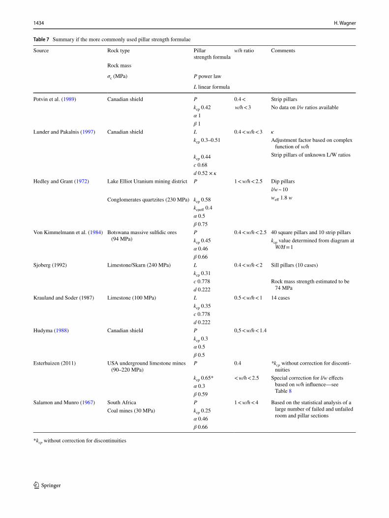
Table 7 gives details of more commonly used pillar strength formulae. A critical examination of the w/h ratios in the fourth column shows that without exception the formulae are based on the performance of pillars with comparatively low w/h ratios, i.e. (w/h) < 4. Several of the formulae are based on the behaviour of rectangular pillars, i.e. pillars with different base dimensions. In this connection, it has to be pointed out that most pillar strength formulae are based on the strength perfor-mance of square pillars. This raises the question of the effec-tive width of rectangular pillars. Experience shows that the
(2)�cp = kcp × �c ×[
c + d ×(
w
h
)]
(MPa).
(3)�cp = kcp × �c ×w�
h�(MPa),
1434 H. Wagner
1 3
Table 7 Summary if the more commonly used pillar strength formulae
*kcp without correction for discontinuities
Source Rock type Pillar strength formula
w/h ratio Comments
Rock mass
σc (MPa) P power law
L linear formula
Potvin et al. (1989) Canadian shield P 0.4 < Strip pillarskcp 0.42 w/h < 3 No data on l/w ratios availableα 1β 1
Lunder and Pakalnis (1997) Canadian shield L 0.4 < w/h < 3 �
kcp 0.3–0.51 Adjustment factor based on complex function of w/h
Strip pillars of unknown L/W ratioskcp 0.44c 0.68d 0.52 × �
Hedley and Grant (1972) Lake Elliot Uranium mining district P 1 < w/h < 2.5 Dip pillarsl/w ~ 10weff 1.8 wConglomerates quartzites (230 MPa) kcp 0.58
kcpeff 0.4α 0.5β 0.75
Von Kimmelmann et al. (1984) Botswana massive sulfidic ores (94 MPa)
P 0.4 < w/h < 2.5 40 square pillars and 10 strip pillarskcp 0.45 kcp value determined from diagram at
W/H = 1α 0.46β 0.66
Sjoberg (1992) Limestone/Skarn (240 MPa) L 0.4 < w/h < 2 Sill pillars (10 cases)kcp 0.31c 0.778 Rock mass strength estimated to be
74 MPad 0.222Krauland and Soder (1987) Limestone (100 MPa) L 0.5 < w/h < 1 14 cases
kcp 0.35c 0.778d 0.222
Hudyma (1988) Canadian shield P 0,5 < w/h < 1.4kcp 0.3α 0.5β 0.5
Esterhuizen (2011) USA underground limestone mines (90–220 MPa)
P 0.4 *kcp without correction for disconti-nuities
kcp 0.65* < w/h < 2.5 Special correction for l/w effects based on w/h influence—see Table 8
α 0.3β 0.59
Salamon and Munro (1967) South Africa P 1 < w/h < 4 Based on the statistical analysis of a large number of failed and unfailed room and pillar sections
Coal mines (30 MPa) kcp 0.25α 0.46β 0.66

1435Deep Mining: A Rock Engineering Challenge
1 3
strength of long pillars is significantly greater than the strength of a square pillar of the same w/h ratio. In the literature, a num-ber of methods to determine the effective width of rectangular pillars can be found which falls in the range
In large-scale in situ coal pillar tests, Wagner (1974) found
that the unconfined periphery of coal pillars contributes relatively little to the load-bearing capability of a pillar. The greatest contribution to the strength of a pillar comes from the confined core. Based on this finding, Wagner proposed the following approach to determine the effective pillar width weff
where Ap , pillar area (m2); Cp , circumference of pillar (m). Galvin et al. (1999) put the following constraint on this for-mulation, namely that weff =
4 × Ap
Cp
should be used only if
wmin/h > 3.In cases where wmin/h < 3 weff = wmin.Esterhuizen et al. (2011) proposed the following adjustment
to the width of rectangular limestone pillars
where w is the minimum width of pillar and LBR is a length–benefit ratio Table 8.
One of the important results of room and pillar investiga-tions in the aftermath of the Coalbrook mining disaster was the need to isolate individual room and pillar mining panels by leaving strong continuous pillars between the panels (Salamon 1967; Wagner 1992; Galvin 2016). The importance of substan-tial interpanel pillars was highlighted by a pillar collapse at the Teutschenthal potash mine where in 1996 an area of 2.5 km2 supported by equal sized salt pillars failed suddenly resulting in an earth tremor of Richter magnitude ML = 4,8 (Minkley and Menzel 1999). Interpanel pillars serve as ventilation and water barriers, and prevent the spread of pillar collapses out-side the mining panel where these occur. For these reasons, it is important that the design of long inter-panel pillars is on a sound footing, i.e. that the issue of the effect of l/w ratio on the strength of strip pillars is resolved.
√
Ap > weff > wmin.
(4)weff =4 × Ap
Cp
(m),
(5)weff = w +
[
4 × Ap
Cp
− w
]
× LBR (m),
A point which deserves particular attention is the effect of natural discontinuities on the strength of very slender pillars, i.e. pillars with w/h < 1. Esterhuizen (1995) has analyzed the effect of jointing on the strength of pillars and found that above a w/h ratio of 5 the deleterious influence of jointing on pillar strength become insignificant. Square pillars with small w/h ratios are particularly sensitive to jointing, Esterhuizen (2006). In cases of a dominant joint direction, rectangular pillars with the long dimension oriented in the dip direction of the joints should be employed instead of square pillars. In mines extract-ing inclined tabular deposits, long pillars oriented in the dip direction are preferred for operational reasons and are better suited to resist down dip strata movement. Care has, however, to be taken in cases where prominent discontinuities are ori-ented in the dip direction. In such situations, an orientation of the long side of pillar in the strike direction is to be preferred.
There is considerable controversy as far the strength of pil-lars with large w/h ratios, so-called squat pillars, is concerned. Compared to more slender pillars, squat pillars have a large confined central core area and very high bearing capacities. Salamon (1982) proposed a pillar strength formula for squat coal pillars
where �cp , strength of squat pillar (MPa); Vp = w2m× h,
(m3); Rm , minimum width to height ratio, wm∕h ; R0 , width to height ratio at which pillar is considered to become squat, a = (� + �)∕3 and b = (� − 2�)∕3 see Table 7 and Eq. (3), and � , a measure of the rate of strength increase once wm∕h exceeds R0.
Conservative values for the transition from the standard pil-lar strength formula to the squat pillar formula proposed by Salamon (1979) and Wagner and Madden (1984) are
Based on the fact that there are very few reported cases of pillar failures with w/h > 3, some authors suggest that the confined core effect on the strength of pillars manifests itself already at W/H around 3 or even lower (Martin and Maybee 2000; Kaiser et al. 2011; Watson et al. 2010).
The problem of assessing the in situ strength of squat pillars stems from the fact that at higher pillar loads the circumfer-ential portions of pillar are extensively fractured and lateral deformation of pillar increases markedly suggesting onset of pillar failure. However, there is usually little or no information
(6)
�cp = kcp × �c × VapRb0
{
b
�
[(
Rm
R0
)�
− 1
]
+ 1
}
(MPa),
R0 = 5, � = 2.5.
Table 8 Values of length to benefit ratio (LBR) for rectangular pillars with different width-to-height ratios
w/h ratio 0.5 0.6 0.7 0.8 0.9 1 1.1 1.2 1.3 1.4
LBR ratio 0.00 0.06 0.22 0.50 0.76 0.89 0.96 0.98 0.99 1
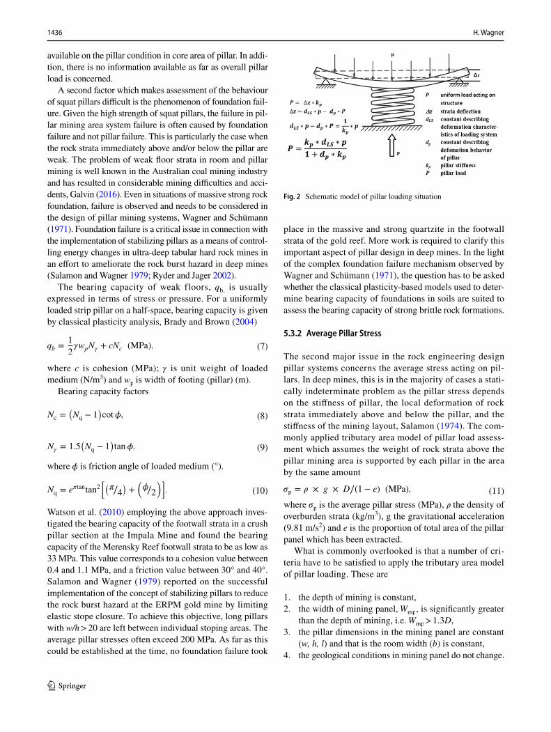
1436 H. Wagner
1 3
available on the pillar condition in core area of pillar. In addi-tion, there is no information available as far as overall pillar load is concerned.
A second factor which makes assessment of the behaviour of squat pillars difficult is the phenomenon of foundation fail-ure. Given the high strength of squat pillars, the failure in pil-lar mining area system failure is often caused by foundation failure and not pillar failure. This is particularly the case when the rock strata immediately above and/or below the pillar are weak. The problem of weak floor strata in room and pillar mining is well known in the Australian coal mining industry and has resulted in considerable mining difficulties and acci-dents, Galvin (2016). Even in situations of massive strong rock foundation, failure is observed and needs to be considered in the design of pillar mining systems, Wagner and Schümann (1971). Foundation failure is a critical issue in connection with the implementation of stabilizing pillars as a means of control-ling energy changes in ultra-deep tabular hard rock mines in an effort to ameliorate the rock burst hazard in deep mines (Salamon and Wagner 1979; Ryder and Jager 2002).
The bearing capacity of weak floors, qb, is usually expressed in terms of stress or pressure. For a uniformly loaded strip pillar on a half-space, bearing capacity is given by classical plasticity analysis, Brady and Brown (2004)
where c is cohesion (MPa); � is unit weight of loaded medium (N/m3) and wp is width of footing (pillar) (m).
Bearing capacity factors
where � is friction angle of loaded medium (°).
Watson et al. (2010) employing the above approach inves-tigated the bearing capacity of the footwall strata in a crush pillar section at the Impala Mine and found the bearing capacity of the Merensky Reef footwall strata to be as low as 33 MPa. This value corresponds to a cohesion value between 0.4 and 1.1 MPa, and a friction value between 30° and 40°. Salamon and Wagner (1979) reported on the successful implementation of the concept of stabilizing pillars to reduce the rock burst hazard at the ERPM gold mine by limiting elastic stope closure. To achieve this objective, long pillars with w/h > 20 are left between individual stoping areas. The average pillar stresses often exceed 200 MPa. As far as this could be established at the time, no foundation failure took
(7)qb =1
2�wpN� + cNc (MPa),
(8)Nc =(
Nq − 1)
cot�,
(9)N� = 1.5(
Nq − 1)
tan�,
(10)Nq = e�tantan2[
(
�∕4)
+(
�∕2
)]
.
place in the massive and strong quartzite in the footwall strata of the gold reef. More work is required to clarify this important aspect of pillar design in deep mines. In the light of the complex foundation failure mechanism observed by Wagner and Schümann (1971), the question has to be asked whether the classical plasticity-based models used to deter-mine bearing capacity of foundations in soils are suited to assess the bearing capacity of strong brittle rock formations.
5.3.2 Average Pillar Stress
The second major issue in the rock engineering design pillar systems concerns the average stress acting on pil-lars. In deep mines, this is in the majority of cases a stati-cally indeterminate problem as the pillar stress depends on the stiffness of pillar, the local deformation of rock strata immediately above and below the pillar, and the stiffness of the mining layout, Salamon (1974). The com-monly applied tributary area model of pillar load assess-ment which assumes the weight of rock strata above the pillar mining area is supported by each pillar in the area by the same amount
where �p is the average pillar stress (MPa), � the density of overburden strata (kg/m3), g the gravitational acceleration (9.81 m/s2) and e is the proportion of total area of the pillar panel which has been extracted.
What is commonly overlooked is that a number of cri-teria have to be satisfied to apply the tributary area model of pillar loading. These are
1. the depth of mining is constant,2. the width of mining panel, Wmp , is significantly greater
than the depth of mining, i.e. Wmp > 1.3D,3. the pillar dimensions in the mining panel are constant
(w, h, l) and that is the room width (b) is constant,4. the geological conditions in mining panel do not change.
(11)�p = � × g × D∕(1 − e) (MPa),
Fig. 2 Schematic model of pillar loading situation

1437Deep Mining: A Rock Engineering Challenge
1 3
In practice, these requirements can only be met in mechanized room and pillar situations in coal and salt mines. In hard rock mines where the rock is excavated by means of drilling and blasting, the requirement of constant mining dimensions is difficult if not impossible to achieve.
Figure 2 illustrates the pillar loading situation and the parameters governing pillar load. As a general rule, the stiffness of the mining system increases with the depth of mining and the deformation modulus of rock mass, and decreases with the width of mining panel. Pillar stiffness is directly proportional to the deformation module of pillar material and the pillar area, and inversely proportional to pillar height. In deep mines, tributary area loading condi-tions are the exception because Wmp << 1.3D. As a result, a significant proportion of the rock strata above the pillar panel is supported by the abutments of the mining panel, i.e. actual pillar stresses tend to be lower than those deter-mined by tributary area model. The real problem arises when the width of mining panel is increased as this will result in an increase in actual average pillar stress. In situ-ations where pillars are already stressed close to the point of their ultimate strength, the increase in panel width can lead to unexpected regional pillar failures. The situation is particularly critical in post-pillar mining situations. Post-pillar mining is often applied in irregular mineral deposits of considerable height. Room and pillar mining takes place in ascending slices commencing in the deepest portion of the deposit. After a slice of about 3–5 m height has been mined, it is backfilled and working on the backfill the next slice is mined. There are known cases where 30 slices and more have been mined in this manner, Wagner et al. (2016). The specific feature of this system of mining is that with every mining step the stiffness of pillars and its strength are reduced. Given the generally small panel width found in post-pillar mining applications, this means that pillar loads decrease as mining progresses, and more and more of the overburden strata are supported by the panel abutments. Considering that with every mining slice w/h becomes smaller the pillar strength decreases. Any significant increase in panel width in an advanced mining stage can result in regional pillar failure.
The discussion has shown that there are a number of criti-cal situations that have to be considered when applying pillar systems in mines. One aspect of pillar mining at depth which deserves particular attention is that of rock bursts. When the stress acting on a mine pillar reaches the level of ultimate pillar strength, the pillar loses its resistance to deformation and yields. Salamon (1970, 1974) has shown that at this critical moment the mode of failure depends on the post-failure characteristics of the pillar and the local stiffness of the mining system. Up to the point of failure, external work has to be done to deform the pillar and the system is stable. Beyond this point, pillar stability will depend on the local
mine stiffness at the position of pillar and the pillar post-fail-ure stiffness, Brady and Brown (1981, 2004). The practical difficulties in assessing pillar stability stem from the lack of reliable information concerning in situ post-failure behav-iour of pillars. This is an area requiring urgent attention.
Closely linked to the issue of pillar stability is that of crush pillars. The concept of crush pillars is receiving con-siderable attention in the South African platinum mining industry. The concept of crush pillars is to develop under-sized stope pillars which fail in a stable manner close to the stope face and to use their residual strength to provide the required support resistance to keep the stope hang-ing wall stable and to prevent back breaks, Watson et al. (2010). Critical design issues are the stiffness of the rock strata close to the stope face and its change with distance from the face, and the w/h ratio which determines peak and residual strengths of the pillars. Another critical dimension is the distance between pillars which should be such that stability of stope hanging wall is ensured.
Design of room and pillar systems is usually based on the classical engineering concept of a factor of safety, Fs , which is defined as the ratio of the strength of the structure and the load acing on the structure. In the case of pillars
where �cp is the pillar strength and �P is the average pillar stress.
In coal mining, the safety factor of pillars in extraction panels is typically 1.6, in secondary developments about 2 and in main developments 2.2–2.5, Wagner (1992). For South African and Australian coal pillars, there exist sta-tistically reliable data concerning the probability of pillar failure for different safety factors, Salamon and Munro (1967), Galvin et al. (1999). In deep German potash mines, pillar safety factors of 2.5 are being used. For hard rock pillars, reliable data on the probability of pillar failure for different factors of safety are largely missing. Particularly uncertain is the situation for very slender pillars, w/h < 0.8, which is not uncommon in hard rock mines, Esterhuizen et al. (2011). The reason for this is the strong influence of discontinuities on the strength of slender pillars.
One of the main findings of the investigations into the causes of the Coalbrook mining disaster and the regional pillar failure at the Teutschenthal potash mine was the absence of inter-panel pillars. This facilitated the mine-wide pillar collapse. Today, standard practice in the design of room and pillar workings in coal mines is to leave a continuous pillar between adjacent room and pillar panels. Experience has shown that a width of such pillars equal to the size of panel pillars is sufficient to prevent spread of pillar collapse from one panel into the adjacent panel,
(12)Fs =�cp
�P,
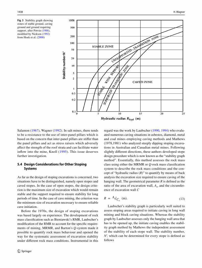
1438 H. Wagner
1 3
Salamon (1967), Wagner (1992). In salt mines, there tends to be a resistance to the use of inter-panel pillars which is based on the concern that inter-panel pillars are stiffer than the panel pillars and act as stress raisers which adversely affect the strength of the roof strata and can facilitate water inflow into the mine, Knoll (1995). This issue deserves further investigation.
5.4 Design Considerations for Other Stoping Systems
As far as the design of stoping excavations is concerned, two situations have to be distinguished, namely open stopes and caved stopes. In the case of open stopes, the design crite-rion is the maximum size of excavation which would remain stable and the support required to ensure stability for long periods of time. In the case of cave mining, the criterion was the minimum size of excavation necessary to ensure reliable cave initiation.
Before the 1970s, the design of stoping excavations was based largely on experience. The development of rock mass classification such as Bieniawski’s RMR, Laubscher’s modification of the RMR to account for the specific require-ments of mining, MRMR, and Barton’s Q-system made it possible to quantify rock mass behaviour and opened the way for the systematic assessment of excavation stability under different rock mass conditions. Instrumental in this
regard was the work by Laubscher (1990, 1994) who evalu-ated numerous caving situations in asbestos, diamond, metal and coal mines employing caving methods and Mathews (1978,1981) who analyzed steeply dipping stoping excava-tions in Australian and Canadian metal mines. Following slightly different directions, these authors developed stope design procedure which is now known as the “stability graph method”. Essentially, this method assesses the rock mass class using either the MRMR or Q-rock mass classification system to describe the rock mass conditions and the con-cept of “hydraulic radius (R)” to quantify by means of back analysis the excavation size required to ensure caving of the hanging wall. The geometrical parameter R is defined as the ratio of the area of excavation wall, As, and the circumfer-ence of excavation wall C
Laubscher’s stability graph is particularly well suited to assess stoping areas required to initiate caving in long wall mining and block caving situations. Whereas the stability graph by Laubscher assesses only the hanging wall area that has to be opened up, the initiate caving enables the stabil-ity graph method by Mathews the independent assessment of the stability of each stope wall. The stability number, Nʹ, which can be determined for every stope is defined as follows
(13)R = As∕Cs(m).
Fig. 3 Stability graph showing zones of stable ground, caving ground and ground requiring support, after Potvin (1988), modified by Nickson (1992) from Hoek et al. (2000)
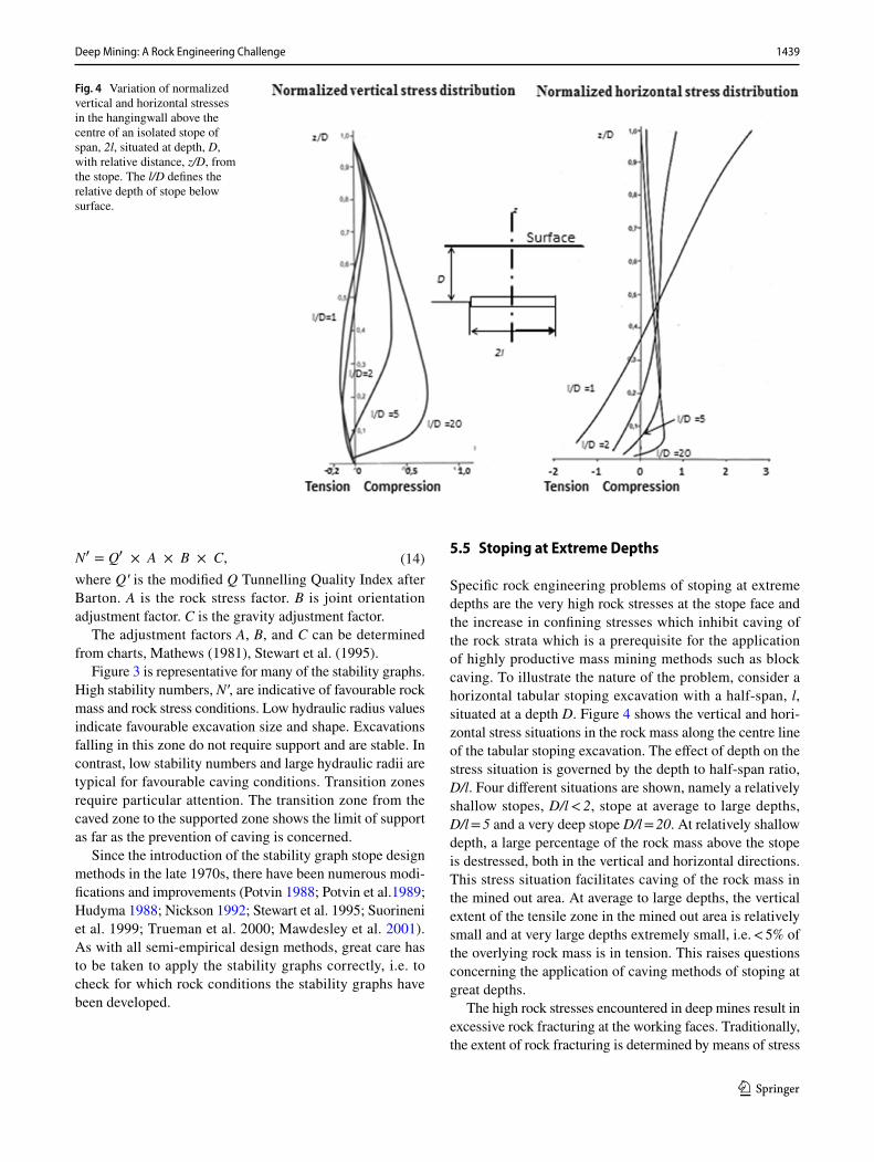
1439Deep Mining: A Rock Engineering Challenge
1 3
where Qʹ is the modified Q Tunnelling Quality Index after Barton. A is the rock stress factor. B is joint orientation adjustment factor. C is the gravity adjustment factor.
The adjustment factors A, B, and C can be determined from charts, Mathews (1981), Stewart et al. (1995).
Figure 3 is representative for many of the stability graphs. High stability numbers, Nʹ, are indicative of favourable rock mass and rock stress conditions. Low hydraulic radius values indicate favourable excavation size and shape. Excavations falling in this zone do not require support and are stable. In contrast, low stability numbers and large hydraulic radii are typical for favourable caving conditions. Transition zones require particular attention. The transition zone from the caved zone to the supported zone shows the limit of support as far as the prevention of caving is concerned.
Since the introduction of the stability graph stope design methods in the late 1970s, there have been numerous modi-fications and improvements (Potvin 1988; Potvin et al.1989; Hudyma 1988; Nickson 1992; Stewart et al. 1995; Suorineni et al. 1999; Trueman et al. 2000; Mawdesley et al. 2001). As with all semi-empirical design methods, great care has to be taken to apply the stability graphs correctly, i.e. to check for which rock conditions the stability graphs have been developed.
(14)N� = Q� × A × B × C,5.5 Stoping at Extreme Depths
Specific rock engineering problems of stoping at extreme depths are the very high rock stresses at the stope face and the increase in confining stresses which inhibit caving of the rock strata which is a prerequisite for the application of highly productive mass mining methods such as block caving. To illustrate the nature of the problem, consider a horizontal tabular stoping excavation with a half-span, l, situated at a depth D. Figure 4 shows the vertical and hori-zontal stress situations in the rock mass along the centre line of the tabular stoping excavation. The effect of depth on the stress situation is governed by the depth to half-span ratio, D/l. Four different situations are shown, namely a relatively shallow stopes, D/l < 2, stope at average to large depths, D/l = 5 and a very deep stope D/l = 20. At relatively shallow depth, a large percentage of the rock mass above the stope is destressed, both in the vertical and horizontal directions. This stress situation facilitates caving of the rock mass in the mined out area. At average to large depths, the vertical extent of the tensile zone in the mined out area is relatively small and at very large depths extremely small, i.e. < 5% of the overlying rock mass is in tension. This raises questions concerning the application of caving methods of stoping at great depths.
The high rock stresses encountered in deep mines result in excessive rock fracturing at the working faces. Traditionally, the extent of rock fracturing is determined by means of stress
Fig. 4 Variation of normalized vertical and horizontal stresses in the hangingwall above the centre of an isolated stope of span, 2l, situated at depth, D, with relative distance, z/D, from the stope. The l/D defines the relative depth of stope below surface.
1440 H. Wagner
1 3
analysis and appropriate failure criteria. As far as tabular mineral deposits are concerned, Cook (1967) and Salamon (1974) have shown that a more appropriate approach to the design of tabular stoping layouts is one based on energy changes associated with enlarging stoping excavations. The simple yet insightful concept of energy release rate (ERR), expressed in (MJ/m2), remains to this day the most acces-sible measure of rock conditions in deep mining situations, Ryder and Jager (2002). It takes into account the effects of depth, rock mass properties, mining span, stoping width, presence of backfill and pillars. Its major shortcoming is that it is insensitive to local geological conditions. Based on field observations and back analysis, design criteria for stoping operations in deep gold mines have been developed. It is suggested that more use is made of energy-based rock engineering concepts in addressing rock engineering prob-lems in deep mines.
5.6 Stoping Sequence
A specific problem in extracting mineral bodies is that stop-ing is a sequential process both in time and in space. The size and shape of mineral bodies usually require that the mineral body is divided into a number of extraction areas (stopes). The size and geometry of stopes are determined by the nature of mineral body and the stoping method which in turn is strongly influenced by rock mechanics considerations. Most important in this regard is whether the stoping excava-tions should remain open, the roof strata should cave or the excavation should be backfilled. In the case of open stoping, the excavation size should be such that the excavation walls are stable over long periods of time. In the case of caving methods, the stope dimensions should be such that the rock strata cave. Stoping layouts which fall into transition zones should be avoided (Fig. 3). The sequence of stoping is deter-mined by the overall mine layout and logistics. This raises the issue of which stope should be mined first and in which sequence stopes should be mined. The importance of the sequence of stoping operations on rock pressure problems encountered in deep mines is a topic which is sadly miss-ing in the mining rock mechanics literature. In general, one distinguishes between advance stoping and retreat stoping. In the case of advance stoping, mining commences close to the shafts and advances towards the boundaries of the mine. The mine infrastructure development follows the stope. The advantage of advance stoping is that few remnant areas are generated and that stoping can commence immediately. A further advantage of advance stoping is that it allows some of the development infrastructure to be situated below the stoped out area, i.e. in destressed rock formations. Exten-sive use of this concept is being made in very deep gold mines in South Africa, Wagner (1983). Remnant areas tend to be highly stressed pieces of ground with difficult rock
conditions and are often characterized by a high incidence of rock bursting. A disadvantage of advance stoping is that usu-ally little or no information of the geological and rock con-ditions exists. A typical example of advance stoping is the room and pillar method which is a standard mining method in shallow to medium depth underground mines. Retreat stoping or retreat mining commences at the boundary of the mine or a mining section and progresses towards the centre of the mine. A feature of retreat mining is that remnants are formed. A prerequisite of retreat mining is that the stope development is completed before stoping can commence. In fully mechanized long wall mining in coal mines, long wall productivity of retreat mining is significantly higher than in advance mining. The reason for this is that long wall operations are not adversely affected by roadway devel-opment. A typical example of the regular development of remnant mining situations is cut-and-fill mining in ascend-ing slices in steeply dipping metal veins. At every mining level, a remnant is being formed when the stope at the lower level approaches an already backfilled upper stope. This is a generic feature of this method of stoping. A special case is room and pillar mining with subsequent extraction of the support pillars. In this case, the primary stoping is on the advance, whereas the extraction of pillars is on the retreat.
Wherever it is feasible, the formation of highly stressed pillars should be avoided. Sometimes this is not possible. A typical example is the stabilizing pillars which serve to control the rock burst hazard in ultra-deep gold mines by minimizing energy changes caused by the extraction of the gold-bearing reefs. These pillars are usually oriented in the strike direction of the reef and develop behind the advancing stope face, Salamon and Wagner (1979). In this situation, the stress on the pillars gradually increases as the stope face advances in the strike direction. The important point is that the stress build-up in the pillar is remote from the area where people work.
Another critical area is stoping in the vicinity of faults and dykes. These structures constitute weaknesses in the rock mass and frequently are the cause of major instabilities, Ryder and Jager (2002). As a general rule, advancing a stope face parallel to the strike direction of the structure should be avoided as it can result in major slippages and ground move-ments. Ideally, stope advance should be along the structure and not towards the structure. Ryder (1987) developed the concept of excess shear stress (ESS) which describes the mechanism of fault slippage induced by stoping activities.
5.7 Remnant Mining
Remnants are isolated portions of the mineral deposit that develop in the process of stoping either due to unfavourable geological conditions or are an inherent feature of the min-ing system, such as cut-and-fill mining in ascending slices
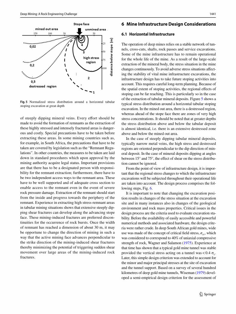
1441Deep Mining: A Rock Engineering Challenge
1 3
of steeply dipping mineral veins. Every effort should be made to avoid the formation of remnants as the extraction of these highly stressed and intensely fractured areas is danger-ous and costly. Special precautions have to be taken before extracting these areas. In some mining countries such as, for example, in South Africa, the precautions that have to be taken are covered by legislation such as the “Remnant Regu-lations”. In other countries, the measures to be taken are laid down in standard procedures which upon approval by the mining authority acquire legal status. Important provisions are that there has to be a designated person with responsi-bility for the remnant extraction; furthermore, there have to be two independent access ways to the remnant area. These have to be well supported and of adequate cross section to enable access to the remnant even in the event of severe rock pressure damage. Extraction of the remnant should start from the inside and progress towards the periphery of the remnant. Experience in extracting high stress-remnant areas in tabular mining situations shows that extensive steeply dip-ping shear fractures can develop along the advancing stope face. These mining-induced fractures are preferred discon-tinuities for the occurrence of rock bursts. Once the width of remnant has reached a dimension of about 30 m, it may be opportune to change the direction of mining in such a way that the active mining face advances perpendicular to the strike direction of the mining-induced shear fractures thereby minimizing the potential of triggering sudden shear movement over large areas of the mining-induced rock fractures.
6 Mine Infrastructure Design Considerations
6.1 Horizontal Infrastructure
The operation of deep mines relies on a stable network of tun-nels, cross-cuts, shafts, rock passes and service excavations. Some of the mine infrastructure has to remain operational for the whole life of the mine. As a result of the large-scale extraction of the mineral body, the stress situation in the mine changes continuously. To avoid adverse stress situations affect-ing the stability of vital mine infrastructure excavations, the infrastructure design has to take future stoping activities into account. This requires careful long-term planning. Because of the spatial extent of stoping activities, the regional effects of stoping can be far reaching. This is particularly so in the case of the extraction of tabular mineral deposits. Figure 5 shows a typical stress distribution around a horizontal tabular stoping excavation. In the mined out area, there is a destressed region, whereas ahead of the stope face there are zones of very high stress concentrations. It should be noted that at greater depths the stress distribution above and below the tabular deposit is almost identical, i.e. there is an extensive destressed zone above and below the mined out area.
In the case of steeply dipping tabular mineral deposits, typically narrow metal veins, the high stress and destressed regions are oriented perpendicular to the dip direction of min-eral deposit. In the case of mineral deposits dipping at angles between 15° and 75°, the effect of shear on the stress distribu-tion cannot be ignored.
From the point of view of infrastructure design, it is impor-tant that the regional stress changes to which the infrastructure excavations will be subjected throughout their operational life are taken into account. The design process comprises the fol-lowing steps, Fig. 6.
It is important to note that changing the excavation posi-tion results in changes of the stress situation at the excavation site and in many instances also in changes of the geological environment and rock mass properties. Critical issues in the design process are the criteria used to evaluate excavation sta-bility. Before the availability of easily accessible and powerful numerical methods and associated hardware, the design crite-ria were rather crude. In deep South African gold mines, wide use was made of the concept of critical field stress, �cr , which was considered to correspond to 40% of uniaxial compressive strength of rock, Wagner and Salamon (1975). Experience at that time has shown that a typical gold mine tunnel was stable provided the vertical stress acting on a tunnel was < 0.4 σc. Later, this simple design criterion was extended to account for the minor and major principal stresses at the site of excavation and the tunnel support. Based on a survey of several hundred kilometres of deep gold mine tunnels, Wiseman (1979) devel-oped a semi-empirical design criterion for the assessment of
Fig. 5 Normalized stress distribution around a horizontal tabular stoping excavation at great depth
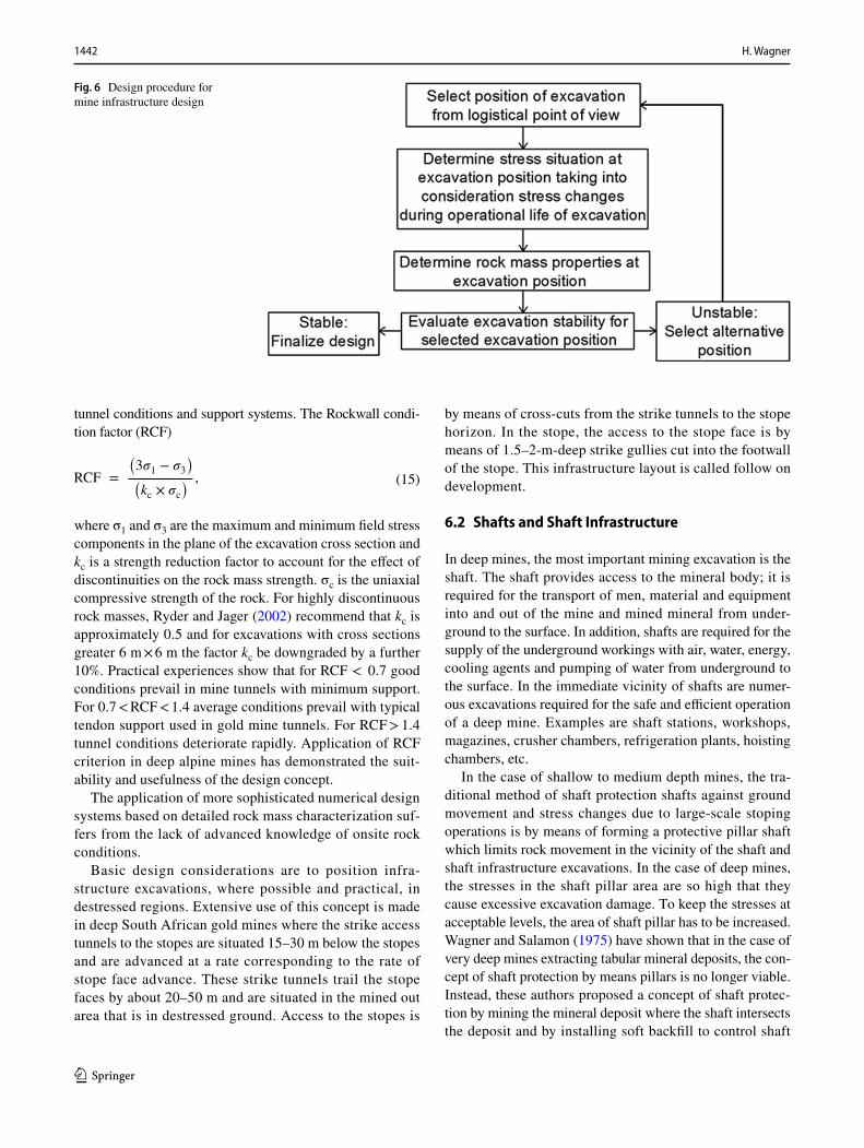
1442 H. Wagner
1 3
tunnel conditions and support systems. The Rockwall condi-tion factor (RCF)
where σ1 and σ3 are the maximum and minimum field stress components in the plane of the excavation cross section and kc is a strength reduction factor to account for the effect of discontinuities on the rock mass strength. σc is the uniaxial compressive strength of the rock. For highly discontinuous rock masses, Ryder and Jager (2002) recommend that kc is approximately 0.5 and for excavations with cross sections greater 6 m × 6 m the factor kc be downgraded by a further 10%. Practical experiences show that for RCF < 0.7 good conditions prevail in mine tunnels with minimum support. For 0.7 < RCF < 1.4 average conditions prevail with typical tendon support used in gold mine tunnels. For RCF > 1.4 tunnel conditions deteriorate rapidly. Application of RCF criterion in deep alpine mines has demonstrated the suit-ability and usefulness of the design concept.
The application of more sophisticated numerical design systems based on detailed rock mass characterization suf-fers from the lack of advanced knowledge of onsite rock conditions.
Basic design considerations are to position infra-structure excavations, where possible and practical, in destressed regions. Extensive use of this concept is made in deep South African gold mines where the strike access tunnels to the stopes are situated 15–30 m below the stopes and are advanced at a rate corresponding to the rate of stope face advance. These strike tunnels trail the stope faces by about 20–50 m and are situated in the mined out area that is in destressed ground. Access to the stopes is
(15)RCF =
(
3�1 − �3)
(
kc × �c) ,
by means of cross-cuts from the strike tunnels to the stope horizon. In the stope, the access to the stope face is by means of 1.5–2-m-deep strike gullies cut into the footwall of the stope. This infrastructure layout is called follow on development.
6.2 Shafts and Shaft Infrastructure
In deep mines, the most important mining excavation is the shaft. The shaft provides access to the mineral body; it is required for the transport of men, material and equipment into and out of the mine and mined mineral from under-ground to the surface. In addition, shafts are required for the supply of the underground workings with air, water, energy, cooling agents and pumping of water from underground to the surface. In the immediate vicinity of shafts are numer-ous excavations required for the safe and efficient operation of a deep mine. Examples are shaft stations, workshops, magazines, crusher chambers, refrigeration plants, hoisting chambers, etc.
In the case of shallow to medium depth mines, the tra-ditional method of shaft protection shafts against ground movement and stress changes due to large-scale stoping operations is by means of forming a protective pillar shaft which limits rock movement in the vicinity of the shaft and shaft infrastructure excavations. In the case of deep mines, the stresses in the shaft pillar area are so high that they cause excessive excavation damage. To keep the stresses at acceptable levels, the area of shaft pillar has to be increased. Wagner and Salamon (1975) have shown that in the case of very deep mines extracting tabular mineral deposits, the con-cept of shaft protection by means pillars is no longer viable. Instead, these authors proposed a concept of shaft protec-tion by mining the mineral deposit where the shaft intersects the deposit and by installing soft backfill to control shaft
Fig. 6 Design procedure for mine infrastructure design
1443Deep Mining: A Rock Engineering Challenge
1 3
movement. Essential for the success of this concept is that mining in the shaft area is symmetric to avoid ride move-ment of shaft. The essential shaft infrastructure is placed below the mined out area that is in destressed ground. Some distance from the shaft symmetrically positioned satellite pillars can be left to take some weight of the back fill in the vicinity of the shaft. This has the additional advantage that important strike tunnels and inclined shafts can be posi-tioned in the destressed area between the satellite pillars. Since the introduction of this shaft protection concept, no new deep shaft on South African gold mines has been pro-tected by shaft pillars.
7 Conclusions
Considerable progress has been made in the past 50 years in the science of rock mechanics. This is particularly in the areas of understanding of rock fracture processes, the sup-port of rock structures based on rock reinforcement con-cepts, the development of numerical methods for structural analysis, the monitoring of mine seismicity and the devel-opment of semi-empirical design concepts are concerned. What is lacking to some extent is the application of the newly gained knowledge and understanding of mine design and mine operation. There are two main reasons for this. The first is a lack of practical rock engineering hand books for mine operators and rock mechanics personnel working on mines. Recently, important steps have been undertaken in this direction. Examples are the hand book by Budavari (1983) “Rock mechanics in mining practice”, the handbook on mine support systems by Hoek et al. (2000) “Support of underground excavations in hard rock”, the handbook by Kaiser et al. (1996) “Canadian rockburst support handbook”, the handbook on “Block caving geomechanics” by Brown published in 2002, the textbook on “Rock mechanics for tab-ular hard rock mines” by Ryder and Jager (2002), the “Pil-lar and roof span design guidelines for underground stone mines” by Esterhuizen et al. (2011) and the book by Galvin (2015) on “Ground engineering-Principles and practices for underground coal mining”. The second reason is the lack of rock engineering courses at universities. In most instances, the emphasis of the courses is on rock mechanics and fun-damental rock mechanics issues. As a result, university graduates are ill prepared as far as finding solutions to the most pressing rock engineering problems encountered by the mines are concerned. The training of mining personnel in the area of applied rock engineering has been identified by the European mining industry as one of the most urgent needs. Under the auspices of the European Raw Materials Initia-tive, a continued education programme in rock engineer-ing for deep mines was recently established to address this need. Open issues that will have to be addressed are the more
extensive use of geophysical tools and methods to predict and monitor rock conditions in mines and the development of practical and reliable criteria and tools for designing rock structures and assessing support needs. From an operational point of view, there is a need to give rock engineering the right place in the mining hierarchy to ensure the safe and economic operation of deep mines.
Acknowledgements Open access funding provided by Montanuniver-sität Leoben.
Open Access This article is distributed under the terms of the Crea-tive Commons Attribution 4.0 International License (http://creat iveco mmons .org/licen ses/by/4.0/), which permits unrestricted use, distribu-tion, and reproduction in any medium, provided you give appropriate credit to the original author(s) and the source, provide a link to the Creative Commons license, and indicate if changes were made.
References
Amadei B, Swolfs HS, Savage WZ (1988) Gravity-induced stresses in stratified rock. Rock Mech Rock Eng 21:1–20
Barton NR, Lien R, Lunde J (1974) Engineering classification of rock masses for the design of tunnel support. Rock Mech 6(4):189–239
Barton NR (2002) Some new Q-value correlations to assist in site characterization and tunnel design. Int J Rock Mech Min Sci 39(2):185–216
Bieniawski ZT (1976) Rock mass classification in rock engineering. Exploration for Rock Engineering 1:97–106
Bieniawski ZT (1978) Determining rock mass deformability—experi-ence from case histories. Int J Rock Mech Min Sci Geomech Abstr 15:237–247
Bieniawski ZT (1989) Engineering rock mass classification a manual. Wiley, New York, pp 205–211
Brady BHG, Brown ET (1981) Energy changes and stability in mine structures design applications of boundary element methods. Trans Inst Min Metall 90:A61–A68
Brown ET (2002) Block caving geomechanics. Julius Kruttschnitt Mineral Research Centre, The University of Queensland, p 515
Brady BHG, Brown ET (2004) Rock mechanics-for underground min-ing, 3rd edn. Kluwer Academic Publishers, Doordrecht, Boston, London
Brown ET, Hood M (1999) Mining rock mechanics, yesterday, today and tomorrow. In Proc. 9th ISRM Congress. Paris, 25-28.08.1999, International Society Rock Mechanics, pp 1551–1576
Brown ET (2009) Estimating the mechanical properties of rock masses. In Potvin Y, Carter J, Dyskin A, Jeffrey R (eds), Proc. SHIRMS. SHIRMS, Perth, Australian Centre for Geomechanics
Cawdle RF (1971) Some notes on recent changes in ore extraction prac-tices in the Zinc Corporation and New Broken Hill Consolidated Limited. Proc Australas Inst Min Metall 181:45–57
COMRO (1988) An Industry guide to methods of ameliorating the hazards of rockfalls and rockbursts-1988 edition. Chamber of Mines of South Africa, Johannesburg
Cook NGW, Hojem JPM (1966) A rigid 50-ton compression and tensile testing machine. J South Afr Mech. Eng 16:89–92
Cook NGW (1967) The design of underground excavations. In Proc. 8th US. Rock Mech. Symp. (C Fairhurst) ed. AIME, New York, pp 167–193

1444 H. Wagner
1 3
Deere DU (1968) Geological considerations. In: Stagg KG, Zienkie-wicz OC (eds) Rock mechanics in engineering practice. Wiley, London, pp 1–20
Diederichs MS (2003) Rock fracture and collapse under low confine-ment conditions. Rock Mech and Rock Eng 36(5):339–381
Diederichs MS, Kaiser PK, Eberhardt E (2004) Damage initiation and propagation in hard rock during tunnelling and the influence of near-face stress rotation. Int J Rock Mech Min Sci 41(5):785–812
Diederichs MS, Carvalho JL (2007) A modified approach for predict-ing strength and post-yield behaviour of high GSI rock masses in strong brittle rocks. In Rock Mechanics meeting Society’s Challenges and Demands. Proceedings 1st Canada-US Rock Mechanics Symposium, Canadian Rock Mechanics Society. Leiden Taylor & Francis, pp 277–285
Durrheim RJ (2010) Mitigating the risk of rockbursts in the deep hard rock mines of South Africa 100 years of research. In Brune J (ed) Extracting the science a century of mining research. Soc Min Metal Explor, pp 156–171 (ISBN 978-0-87335-322-9)
Edelbro C (2008) Strength, fallouts and numerical modelling of hard rock masses. In Dissertation. Lulea University of Technology, Lulea. Mining and Geotechnical Engineering
Esterhuizen GS, Dolinar DR, Ellenberger JL, Prosser LJ (2011) Pillar and roof span guidelines for underground stone mines NIOSH, IC 9526. US Department of Health & Human Services, Pittsburg
Esterhuizen GS (1995) Rock engineering evaluation of jointing in South African coal seams and its potential effect on coal pillar strength. Mechanics of Jointed Faulted Rock. Rosmanith (ed), Balkema, Rotterdam, pp 807–811
Esterhuizen GS (2006) Evaluation of the strength of slender pillars. Trans Soc Min Metal Explor 320:69–76
Galvin JM, Hebblewhite BK, Salamon MDG (1999) University of New South Wales pillar strength determinations for Australian and South African mining conditions. In Mark C, Heasley KA, Ian-nocchione AT, Tuchmann RJ (eds) Proc. 2nd Int. workshop on coal pillar mechanics and design, Vail, pp 63–71, NIOSH IC. 9448, US Dept. Health & Human Services, Pittsburg.
Galvin JM (2016) Ground engineering-principles and practices for underground coal mining. Springer, Cham, Heidelberg, New York, Dordrecht, London, p 684
Gardner FJ (1971) History of rock bolting. In Proceedings Symp Rock bolting, llawarra Branch, Australas Inst Min Metall, pp 2.1–2.12
Gay NC, Spencer D, van Wyk JJ, van der Heever PK (1984) The con-trol of geological and mining parameters in the Klerksdorp gold mining district. In Gay NC, Wainright H (eds). Proceedings of the 1st International Congress on Rockbursts and Seismicity in Mines, Johannesburg, 1982, SAIMM, Johannesburg, pp 107–120
Hardy M, Agapito JFT (1975) Pillar design in underground oil shale mines. In Fairhurst, Crouch SL (eds) Design methods in rock engineering. Proceedings 16th US-rock mechanics symposium. US Rock Mechanics Society. New York, ASCE, pp 257–265
Hedley DGF, Grant F (1972) Stope and pillar design for Elliot Lake Uranium mines. CIM Bull 65:37
Hoek E, Brown ET (1980) Underground excavations in rock. Inst Min Metall, London
Hoek E, Brown ET (1988) The Hoek-Brown failure criterion-a 1988 update. In Proceedings of 15th Can Rock Mech Symp, University of Toronto, pp 3–38
Hoek E, Kaiser PK, Bawden WF (2000) Support of underground excavations in hard rock, 5th edn. A.A Balkema Publishers, Rotterdam
Hoek E, Carranza-Torres C, Corkum B (2002) Hoek-Brown failure criterion-2002 ed. In Proceedings 5th North American Rock Mechanics Symposium and 17th Tunnelling Association of Canada Conference NARMS-TAC 2002, July 7–10, University of Toronto, pp 267–271
Hoek E (2004) Estimates of rock mass strength. Discussion paper #4. www.rocscience.com
Hoek E, Diederichs MS (2006) Empirical estimation of rock mass modulus. Int J Rock Mech Min Sci 43:203–215
Hoek E, Carter TG, Diederichs MS (2013) Quantification of the geo-logical strength index—chart. In Paper presented at the 47th US Rock Mechanics /Geomechanics Symposium. San Francisco, CA, USA
Hudyma MR (1988) Rib pillar design in open stope mining. MSc The-sis. In The University of British Columbia, Vancouver. Mining and Mineral Processing Engineering
Jaeger JC, Cook NGW (1979) Fundamentals of rock mechanics, 3rd edn. Chapman & Hall, London
Jing L, Hudson JA (2002) Numerical methods in rock mechanics. Int J Rock Mech Min Sci 39(4):409–427
Junker M et al (2006) Gebirgsbeherrschung von Flözstrecken. Hand-book prepared by a group of 25 specialists. Glückauf, Essen, p 656
Kaiser PK, McCreath DR, Tannant DD (1996) Canadian rockburst support handbook. Geomechanics Research Centre-Mirarco, Canada
Kaiser PK, Diederichs MS, Martin CD, Sharp, J, Steiner W (2000) Underground works in hard rock tunnelling and mining. In Proceedings GeoEng 2000, Technomic Publishing Company, Lancaster, vol 1, pp 841–926
Kaiser PK, Kim G-H, Bewick RP, Valley B (2011) Rock mass strength at depth and implications for pillar design. J Mining Technology-Trans Inst Min Metall Sect A 120:170–179
Knoll P (1995) Personal contribution in connection with the regional pillar failure at the Teutschenthal potash mine near Halle in Germany
Konietzky H, Frühwirth T, Luge H (2012) A new large dynamic rockmechanical direct shear box device. Rock Mech Rock Eng 45:427–432
Krauland N, Söder P, Agmalm G (1989) Determination of rock mass strength by rock mass classification some experience and questions from Boliden mines. Int. J Rock Mech Min Sci 26(1):115–123
Krauland N, Söder P (1987) Determining pillar strength from pillar failure observation. E&MJ 188:34–40
Lang TA (1961) Theory and practice of rock bolting. Trans Soc Min Eng AIME 220:333–348
Laubscher DH (1990) A geomechanics classification system for the rating of rock mass in mine design. J South Afr Inst Min Metall 90:257–273
Laubscher DH (1994) Cave mining-the state of the art. J South Afr Inst Min Metall 94:279–293
Li CC, Stjern G, Myrvang A (2014) A review on the performance of conventional and energy-absorbing rockbolts. J Rock Mech Geotech Eng 6:3156–3327
Lunder PJ (1994) Hard rock pillar strength estimation an applied empirical approach. In MSc Thesis, The University of British Columbia, Vancouver, Canada. Dept of Mining and Mineral Processing Engineering
Lunder PJ, Pakalnis RC (1997) Determination of the strength of hard rock pillars. CIM-Bull 90:51–55
Malan DF, Napier JAL (2011) The design of stable pillars in the Bushveld complex mines a problem solved? J South Afr Inst Min Metall 111:821–836
Martin CD, Maybee WG (2008) The strength of hard rock pillars. Int J Rock Mech Min Sci 37:1239–1246
Mathews KE, Hoek E, Whyllie DC, Stewart SBV (1981) Prediction of stable excavation spans for mining at depth below 1000 m in hard rock mines. In CANMET Report DSS Serial No. OSQ80-00081
1445Deep Mining: A Rock Engineering Challenge
1 3
Mawdesley C, Trueman R, Witten W (2001) Extending the Mathews stability for open stope design. Trans IMM (Sect A) 110:A27–A39
Maybee WG (2000) Pillar design in hard brittle rock. MSc Thesis. In Laurentian University, Sudbury, Ontario, Canada
McCutchen WR (1988) Some elements of a theory for in situ stress. Int J Rock Mech Min Sci Geomech Abstr 19:201–203
Minkley W, Menzel W (1999) Pre-calculation of a mine collapse rock burst at Teutschenthal on 11 September 1996. In 9th ISRM Congr. 25–28 August 1999, Paris, France, Publ. ISRM
National Coal Bord (1975) Subsidence Engineers Handbook. In 2nd (rev) edn. National Coal Bord Mining Dept. London
Nickson SD (1992) Cable support guidelines for hard rock underground mine operations. In MASc. thesis, Dept. Mining and Minerals Processing, University of British Columbia
Nikolic M, Roje-Bonacci T, Ibrahimgebovic A (2016) Overview of the numerical methods for the modelling of rock mechanics problems. Techn Gazette 23(2):627–637
Obert L, Duvall WI (1967) Rock mechanics and the design of structures in rock. Wiley, Hoboken
Palmstrom A, Singh R (2001) The deformation module of rock masses comparisons between in situ tests and indirect estimates. Tunnell UndergrSpace Technol 16:115–131
Potvin Y (1985) Investigation of underground pillar design procedures. In MSc. Thesis, The University of British Columbia, Vancouver
Potvin Y (1988) Empirical stope design in Canada. In PhD thesis, Depart-ment of Mining and Minerals Processing. University of British Columbia
Potvin Y, Hudyma MR, Miller HDS (1989) Design guidelines for open stope support. CIM Bull 82(926):53–62
Rabcevicz L (1957) Modellversuche mit Ankerung in kohäsionslosem Material. Die Bautechnik 34(5):171–173
Ryder JA (1987) Excess shear stress (ESS) an engineering criterion for assessing unstable slip and associated rockburst hazards. In Herget G, Vongpaisal S (eds) Proceedings 6th Congr Int Soc Rock Mech, Montreal, vol 2, pp 1211–15, AA Balkema Rotterdam
Ryder JA, Jager AJ (2002) A handbook on rock engineering practice for tabular hard-rock mines. SIMRAC, Johannesburg
Salamon MDG, Munro AH (1967) A study of the strength of coal pillars. J South Afr Inst Min Metall 67:55–67
Salamon MDG (1967) A method of designing bord and pillar workings. J South Afr Inst Min Metall 67:68–78
Salamon MDG (1970) Stability, instability and the design of pillar work-ings. Int J Rock Mech Min Sci 7(6):613–631
Salamon MDG (1974) Rock mechanics of underground excavations. In Advances in rock mechanics, Proceedings 3rd Congr Int Soc Rock Mech, Denver, vol 1B, pp 951–1099. Nat. Acad. Sci., Washington, DC
Salamon, MDG (1983) Rockburst hazard and the fight for its alleviation in South African gold mines. In Rockbursts-Prediction and Control, Instn Min Metall, London
Salamon MDG, Wagner H (1979) Role of stabilizing pillars in alleviating the rockburst hazard in deep mines. In Proceedings 4th Congr Int Soc Rock Mech, Montreux, vol 2, pp 561–566
Salamon MDG, Galvin JM, Hocking G, Anderson I (1996) Coal Pil-lar Strength from Back-Calculation. University New South Wales, Sydney
Salamon MDG (1982) Report to Wankie Colliery (Unpublished).Serafim JL, Pereira JP (1983) Considerations of the geomechanical clas-
sification of Bieniawski. In Proceedings int symp on engineering geology and underground construction, Lisbon, vol 1, pp 33–42
Sheorey PR (1994) A theory for in situ stresses in isotropic and trans-versely isotropic rock. Int J Rock Mech Min Sci Geomech Abst 31:23–34
Sjöberg J (1992) Failure modes and pillar behaviour in the Zinkgruvan mine. In Tillerson JA, Wawersik WA (eds) Proceedings of 33rd
US Rock Mechanics Symposium, Santa Fe. US Rock Mechanics Society. Rotterdam A.A. Balkema, pp 491–500
Suorineni FT, Kaiser PK, Tannant DD (2001) Likelihood statistics for the interpretation of the stability graph for open stope design. Int J Rock Mech Min Sci 38:735–744
Trueman R, Mikula P (2000) Mawdesley C and Harris N (2000) Experi-ence in Australia with the application of the Mathew’s method for open stope design. CIM-Bull 93(1036):162–167
Von Kimmelmann MR, Hyde B, Madgwick RJ (1984) The use of com-puter applications at BLC Limited in planning pillar extraction and design of mining layouts. In Brown ET, Hudson JA (eds) Design and Performance of Underground Excavations, Proceedings of ISRM-Symposium, pp 53–63
Van der Merwe JN (2008) Beyond Coalbrook-What did we really learn? J South Afr Inst Min Metall. 108:857–868
Van Heerden WL (1987) General relations between static and dynamic moduli of rocks. Int J Rock Mech Min Sci Geomech Abstr 25:381–385
Wagner H, Schümann EHR (1971) The stamp-load bearing strength of rock an experimental and theoretical investigation. Rock Mech 3:185–207
Wagner H (1974) Determination of the complete load-deformation char-acteristics of coal pillars. In Advances in Rock Mechanics Pro-ceedings of the 3rd Congress of the International Society for Rock Mechanics, Denver, Colorado, pp 1076–1081
Wagner H, Salamon, MDG (1975) Strata control techniques in shafts and large excavations. Papers and Discussions, Association of Mine Manager of South Africa 1972-73, pp 123–138. Chamber of Mines of South Africa
Wagner H (1983) Protection of service excavations. In Budavari S (ed) Rock mechanics in mining practice, Chapter 9, Johannesburg, South Afr Inst Min Metall, pp 201–220
Wagner H, Madden BJ (1984) 15 years of experience with the design of coal pillars in shallow South African collieries an evaluation of the performance of the design procedures and recent improve-ments. In Design performance of underground excavations, ISRM Symposium, Cambridge, 3–6 September 1984, London, British Geotechnical Society, pp 391–399
Wagner H (1984) Support requirements of rockburst conditions. In: Gay NC, Wainwright EH (eds) Rockbursts and Seismicity in Mines. South Afr Inst Min Metall, Johannesburg, pp 209–218
Wagner H (1987) Design and support of underground excavations in highly stressed rock. In Herget G, Vongpaisal S (eds) Proceed-ings 6th Congress of Int Soc Rock Mech, Montreal, Canada. A.A. Balkema, Rotterdam, pp 1443–1457
Wagner H (1992) Pillar design in South African collieries. In Coal Pillar Design Workshop, 33rd US Rock Mechanics Symposium, 7 June 1992, Santa Fe, New Mexico
Wagner H (1995) Roof bolt mechanics—Module 4—Roadway and pillar mechanics workshop stage II. Sydney Dept Mining Engineering, University of New South Wales
Wagner H (2010) The management of heat flow in deep mines. Geomech Tunnell 3(5):157
Wagner H, Blaha H (2011) Comments on the state of art of design of pil-lar systems. Workshop calculation methods in geotechnics—failure mechanisms and determination of parameters. ÖGG-Herbsttagung, 12. Oktober 2011, Salzburg. In Compilation of Extended Abstracts, pp 67–74
Wagner H (2015) Zur Frage der Unterschiede von Bergbau und Tunnelbau. Berg und Hüttenmännische Monatshefte BHM 160(2015):363–372
Wagner H, Ladinig T, Blaha H (2016) Design considerations for pillar systems in deep mines. Geomech Tunnell 9:524–528
Walton G, Diederichs MS, Punkkinen A (2015) The influence of con-stitutive model selection on predicted stresses and yield in deep

1446 H. Wagner
1 3
mine pillars—a case study at the Creighton mine, Sudbury, Canada. Geomech Tunnell 8(5):441–448
Watson BP, Kuijpers JS, Stacey TR (2010) Design of Merensky Reef crush pillars. J South Afr Inst Min Metall 110:581–591
Wawersik WR, Fairhurst C (1970) A study of brittle fracture in laboratory compression tests. Int J Rock Mech Min Sci 7(5):561–575
Wiseman N (1979) Factors effecting the the design andcvonditions of mine tunnels. In Research Report No. G01G10, Chamber of Mines Research Organization, Johannesburg, South Africa
Zang A, Stephansson O (2010) Stress field of the earth crust. Springer, Netherlands, p 327
Publisher’s Note Springer Nature remains neutral with regard to jurisdictional claims in published maps and institutional affiliations.