Embed Size (px)
DESCRIPTION
Deep foundations
Citation preview
A deep foundation installation for a
bridge in Napa, California, United
States.
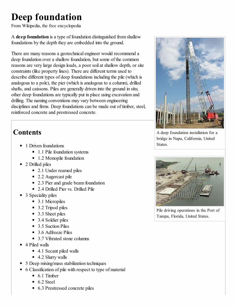
Pile driving operations in the Port of
Tampa, Florida, United States.
Deep foundationFrom Wikipedia, the free encyclopedia
A deep foundation is a type of foundation distinguished from shallowfoundations by the depth they are embedded into the ground.
There are many reasons a geotechnical engineer would recommend adeep foundation over a shallow foundation, but some of the commonreasons are very large design loads, a poor soil at shallow depth, or siteconstraints (like property lines). There are different terms used todescribe different types of deep foundations including the pile (which isanalogous to a pole), the pier (which is analogous to a column), drilledshafts, and caissons. Piles are generally driven into the ground in situ;other deep foundations are typically put in place using excavation anddrilling. The naming conventions may vary between engineeringdisciplines and firms. Deep foundations can be made out of timber, steel,reinforced concrete and prestressed concrete.
Contents
1 Driven foundations
1.1 Pile foundation systems
1.2 Monopile foundation2 Drilled piles
2.1 Under reamed piles
2.2 Augercast pile
2.3 Pier and grade beam foundation
2.4 Drilled Pier vs. Drilled Pile3 Speciality piles
3.1 Micropiles
3.2 Tripod piles
3.3 Sheet piles
3.4 Soldier piles
3.5 Suction Piles
3.6 Adfreeze Piles
3.7 Vibrated stone columns4 Piled walls
4.1 Secant piled walls
4.2 Slurry walls
5 Deep mixing/mass stabilization techniques
6 Classification of pile with respect to type of material
6.1 Timber
6.2 Steel
6.3 Prestressed concrete piles
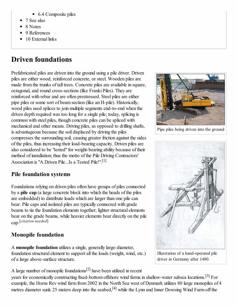
Pipe piles being driven into the ground
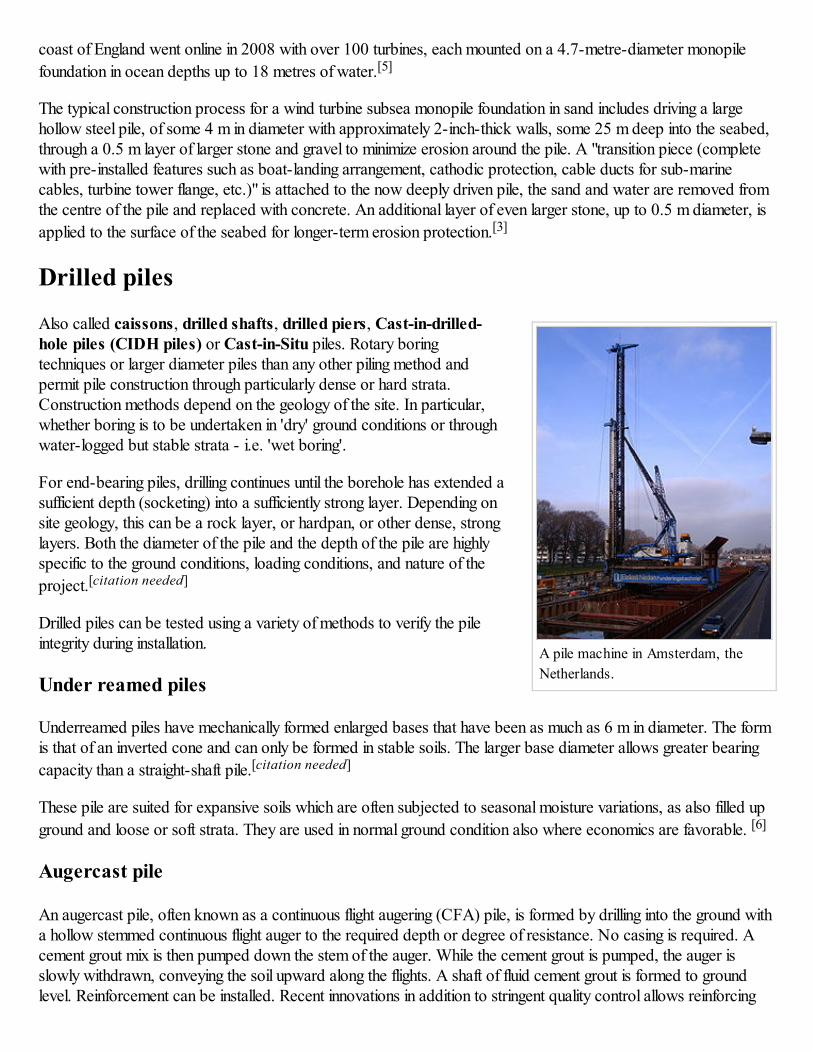
Illustration of a hand-operated pile
driver in Germany after 1480.
6.4 Composite piles
7 See also
8 Notes
9 References
10 External links
Driven foundations
Prefabricated piles are driven into the ground using a pile driver. Drivenpiles are either wood, reinforced concrete, or steel. Wooden piles aremade from the trunks of tall trees. Concrete piles are available in square,octagonal, and round cross-sections (like Franki Piles). They arereinforced with rebar and are often prestressed. Steel piles are eitherpipe piles or some sort of beam section (like an H-pile). Historically,wood piles used splices to join multiple segments end-to-end when thedriven depth required was too long for a single pile; today, splicing iscommon with steel piles, though concrete piles can be spliced withmechanical and other means. Driving piles, as opposed to drilling shafts,is advantageous because the soil displaced by driving the pilescompresses the surrounding soil, causing greater friction against the sidesof the piles, thus increasing their load-bearing capacity. Driven piles arealso considered to be "tested" for weight-bearing ability because of theirmethod of installation; thus the motto of the Pile Driving Contractors'
Association is "A Driven Pile...Is a Tested Pile!".[1]
Pile foundation systems
Foundations relying on driven piles often have groups of piles connectedby a pile cap (a large concrete block into which the heads of the pilesare embedded) to distribute loads which are larger than one pile canbear. Pile caps and isolated piles are typically connected with gradebeams to tie the foundation elements together; lighter structural elementsbear on the grade beams, while heavier elements bear directly on the pile
cap.[citation needed]
Monopile foundation
A monopile foundation utilizes a single, generally large-diameter,foundation structural element to support all the loads (weight, wind, etc.)of a large above-surface structure.
A large number of monopile foundations[2] have been utilized in recent
years for economically constructing fixed-bottom offshore wind farms in shallow-water subsea locations.[3] Forexample, the Horns Rev wind farm from 2002 in the North Sea west of Denmark utilizes 80 large monopiles of 4
metres diameter sunk 25 meters deep into the seabed,[4] while the Lynn and Inner Dowsing Wind Farm off the
A pile machine in Amsterdam, the
Netherlands.
coast of England went online in 2008 with over 100 turbines, each mounted on a 4.7-metre-diameter monopile
foundation in ocean depths up to 18 metres of water.[5]
The typical construction process for a wind turbine subsea monopile foundation in sand includes driving a largehollow steel pile, of some 4 m in diameter with approximately 2-inch-thick walls, some 25 m deep into the seabed,through a 0.5 m layer of larger stone and gravel to minimize erosion around the pile. A "transition piece (completewith pre-installed features such as boat-landing arrangement, cathodic protection, cable ducts for sub-marinecables, turbine tower flange, etc.)" is attached to the now deeply driven pile, the sand and water are removed fromthe centre of the pile and replaced with concrete. An additional layer of even larger stone, up to 0.5 m diameter, is
applied to the surface of the seabed for longer-term erosion protection.[3]
Drilled piles
Also called caissons, drilled shafts, drilled piers, Cast-in-drilled-hole piles (CIDH piles) or Cast-in-Situ piles. Rotary boringtechniques or larger diameter piles than any other piling method andpermit pile construction through particularly dense or hard strata.Construction methods depend on the geology of the site. In particular,whether boring is to be undertaken in 'dry' ground conditions or throughwater-logged but stable strata - i.e. 'wet boring'.
For end-bearing piles, drilling continues until the borehole has extended asufficient depth (socketing) into a sufficiently strong layer. Depending onsite geology, this can be a rock layer, or hardpan, or other dense, stronglayers. Both the diameter of the pile and the depth of the pile are highlyspecific to the ground conditions, loading conditions, and nature of the
project.[citation needed]
Drilled piles can be tested using a variety of methods to verify the pileintegrity during installation.
Under reamed piles
Underreamed piles have mechanically formed enlarged bases that have been as much as 6 m in diameter. The formis that of an inverted cone and can only be formed in stable soils. The larger base diameter allows greater bearing
capacity than a straight-shaft pile.[citation needed]
These pile are suited for expansive soils which are often subjected to seasonal moisture variations, as also filled up
ground and loose or soft strata. They are used in normal ground condition also where economics are favorable. [6]
Augercast pile
An augercast pile, often known as a continuous flight augering (CFA) pile, is formed by drilling into the ground witha hollow stemmed continuous flight auger to the required depth or degree of resistance. No casing is required. Acement grout mix is then pumped down the stem of the auger. While the cement grout is pumped, the auger isslowly withdrawn, conveying the soil upward along the flights. A shaft of fluid cement grout is formed to groundlevel. Reinforcement can be installed. Recent innovations in addition to stringent quality control allows reinforcing
cages to be placed up to the full length of a pile when required. A typical reinforcing cage will consist of 4 to 8 barsfrom #5 to #8 bars typically 1/3 the length of the pile with longitudinal circular ties spaced along the length of thecage. Where tension loads are present it is typical to see a single full length bar placed at the center of each pile.
Augercast piles cause minimal disturbance, and are often used for noise and environmentally sensitive sites.Augercast piles are not generally suited for use in contaminated soils, due to expensive waste disposal costs. Incases such as these however a displacement pile may provide the cost efficiency of an augercast pile and minimalenvironmental impact. In ground containing obstructions or cobbles and boulders, augercast piles are less suitableas refusal above the design pile tip elevation may be encountered. In certain cases drill motors that produce more
torque and horsepower may be able to mitigate these events.[citation needed]
Pier and grade beam foundation
In drilled pier foundations, the piers can be connected with grade beams on which the structure sits, sometimes withheavy column loads bearing directly on the piers. In some residential construction, the piers are extended above theground level and wood beams bearing on the piers are used to support the structure. This type of foundation resultsin a crawl space underneath the building in which wiring and duct work can be laid during construction or re-
modelling.[7]
Drilled Pier vs. Drilled Pile
There is a difference between the terms "drilled pier" and "drilled pile".
Drilled Pier
Consists of concrete and a rebar cage
CSL testing is performed
May or may not have permanent/temporary casing
Drilled Pile
Consists of concrete, a pile, and may or may not have a rebar cage
CSL tests are not typically performed
May or may not have permanent/temporary casing
Speciality piles
Micropiles
Micropiles, also called mini piles, are often used for underpinning. They are also used to create foundations for avariety of project types, including highway, bridge and transmission tower projects. They are especially useful at
sites with difficult or restricted access, or with environmental sensitivity.[8][9] Micropiles are made of steel withdiameters of 60 to 200 mm. Installation of micropiles through top soil, sand and cobblestones overburden and intosoil rock can be achieved using Air Rotary or Mud Rotary drilling, impact driving, jacking, vibrating or screwing
machinery.[10]
Tripod piles
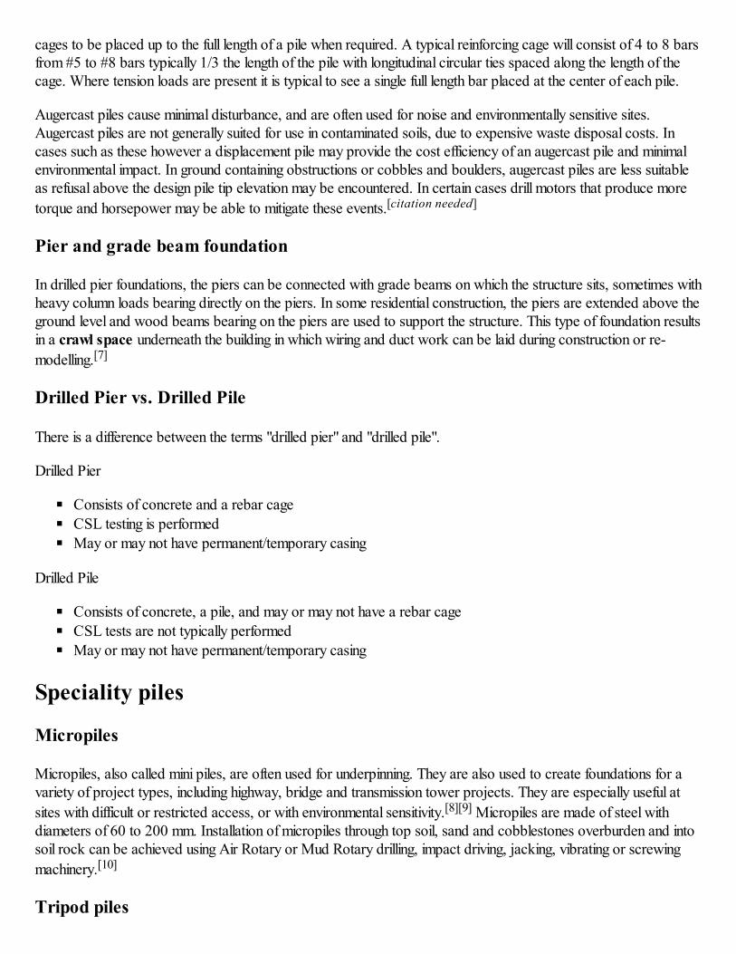
Sheet piles are used to restrain soft
soil above the bedrock in this
excavation
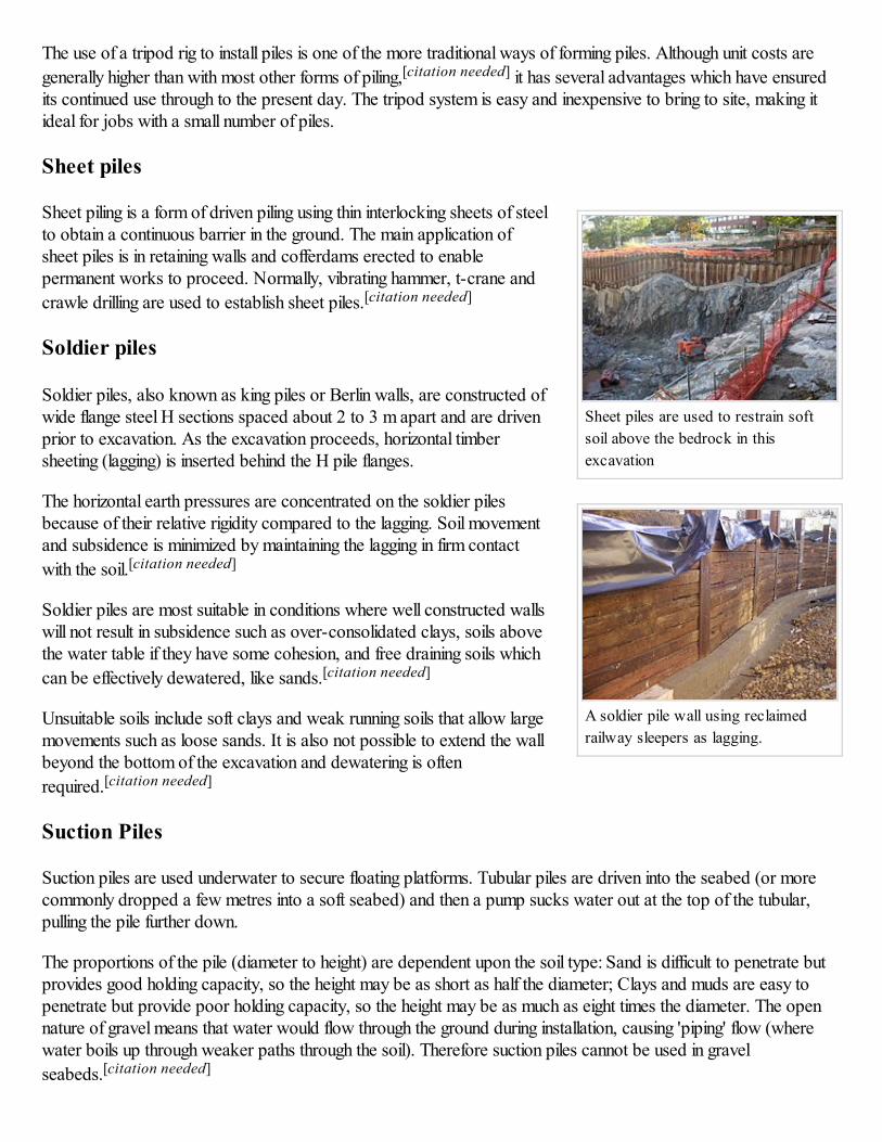
A soldier pile wall using reclaimed
railway sleepers as lagging.
The use of a tripod rig to install piles is one of the more traditional ways of forming piles. Although unit costs are
generally higher than with most other forms of piling,[citation needed] it has several advantages which have ensuredits continued use through to the present day. The tripod system is easy and inexpensive to bring to site, making itideal for jobs with a small number of piles.
Sheet piles
Sheet piling is a form of driven piling using thin interlocking sheets of steelto obtain a continuous barrier in the ground. The main application ofsheet piles is in retaining walls and cofferdams erected to enablepermanent works to proceed. Normally, vibrating hammer, t-crane and
crawle drilling are used to establish sheet piles.[citation needed]
Soldier piles
Soldier piles, also known as king piles or Berlin walls, are constructed ofwide flange steel H sections spaced about 2 to 3 m apart and are drivenprior to excavation. As the excavation proceeds, horizontal timbersheeting (lagging) is inserted behind the H pile flanges.
The horizontal earth pressures are concentrated on the soldier pilesbecause of their relative rigidity compared to the lagging. Soil movementand subsidence is minimized by maintaining the lagging in firm contact
with the soil.[citation needed]
Soldier piles are most suitable in conditions where well constructed wallswill not result in subsidence such as over-consolidated clays, soils abovethe water table if they have some cohesion, and free draining soils which
can be effectively dewatered, like sands.[citation needed]
Unsuitable soils include soft clays and weak running soils that allow largemovements such as loose sands. It is also not possible to extend the wallbeyond the bottom of the excavation and dewatering is often
required.[citation needed]
Suction Piles
Suction piles are used underwater to secure floating platforms. Tubular piles are driven into the seabed (or morecommonly dropped a few metres into a soft seabed) and then a pump sucks water out at the top of the tubular,pulling the pile further down.
The proportions of the pile (diameter to height) are dependent upon the soil type: Sand is difficult to penetrate butprovides good holding capacity, so the height may be as short as half the diameter; Clays and muds are easy topenetrate but provide poor holding capacity, so the height may be as much as eight times the diameter. The opennature of gravel means that water would flow through the ground during installation, causing 'piping' flow (wherewater boils up through weaker paths through the soil). Therefore suction piles cannot be used in gravel
seabeds.[citation needed]
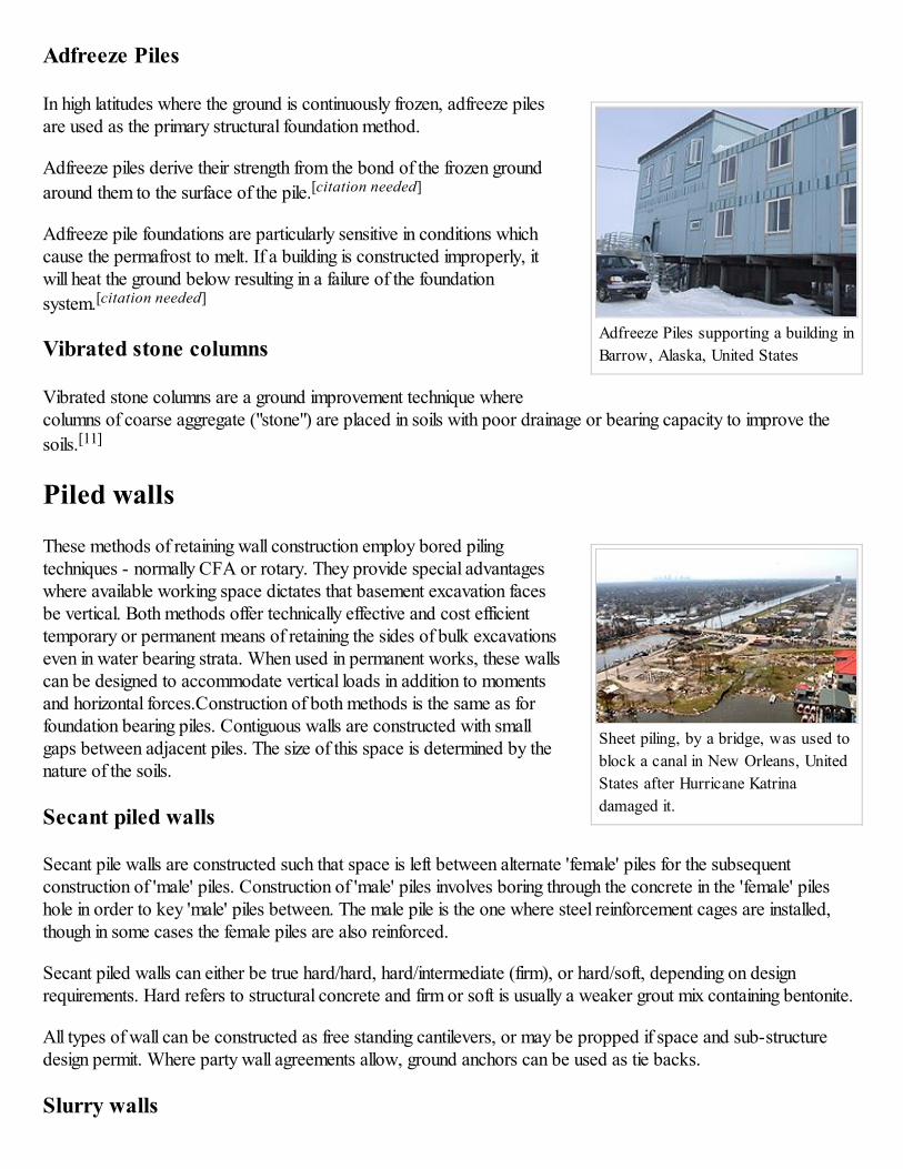
Adfreeze Piles supporting a building in
Barrow, Alaska, United States
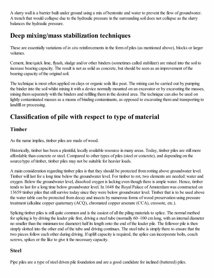
Sheet piling, by a bridge, was used to
block a canal in New Orleans, United
States after Hurricane Katrina
damaged it.
Adfreeze Piles
In high latitudes where the ground is continuously frozen, adfreeze pilesare used as the primary structural foundation method.
Adfreeze piles derive their strength from the bond of the frozen ground
around them to the surface of the pile.[citation needed]
Adfreeze pile foundations are particularly sensitive in conditions whichcause the permafrost to melt. If a building is constructed improperly, itwill heat the ground below resulting in a failure of the foundation
system.[citation needed]
Vibrated stone columns
Vibrated stone columns are a ground improvement technique wherecolumns of coarse aggregate ("stone") are placed in soils with poor drainage or bearing capacity to improve the
soils.[11]
Piled walls
These methods of retaining wall construction employ bored pilingtechniques - normally CFA or rotary. They provide special advantageswhere available working space dictates that basement excavation facesbe vertical. Both methods offer technically effective and cost efficienttemporary or permanent means of retaining the sides of bulk excavationseven in water bearing strata. When used in permanent works, these wallscan be designed to accommodate vertical loads in addition to momentsand horizontal forces.Construction of both methods is the same as forfoundation bearing piles. Contiguous walls are constructed with smallgaps between adjacent piles. The size of this space is determined by thenature of the soils.
Secant piled walls
Secant pile walls are constructed such that space is left between alternate 'female' piles for the subsequentconstruction of 'male' piles. Construction of 'male' piles involves boring through the concrete in the 'female' pileshole in order to key 'male' piles between. The male pile is the one where steel reinforcement cages are installed,though in some cases the female piles are also reinforced.
Secant piled walls can either be true hard/hard, hard/intermediate (firm), or hard/soft, depending on designrequirements. Hard refers to structural concrete and firm or soft is usually a weaker grout mix containing bentonite.
All types of wall can be constructed as free standing cantilevers, or may be propped if space and sub-structuredesign permit. Where party wall agreements allow, ground anchors can be used as tie backs.
Slurry walls
A slurry wall is a barrier built under ground using a mix of bentonite and water to prevent the flow of groundwater.A trench that would collapse due to the hydraulic pressure in the surrounding soil does not collapse as the slurrybalances the hydraulic pressure.
Deep mixing/mass stabilization techniques
These are essentially variations of in situ reinforcements in the form of piles (as mentioned above), blocks or largervolumes.
Cement, lime/quick lime, flyash, sludge and/or other binders (sometimes called stabilizer) are mixed into the soil toincrease bearing capacity. The result is not as solid as concrete, but should be seen as an improvement of thebearing capacity of the original soil.
The technique is most often applied on clays or organic soils like peat. The mixing can be carried out by pumpingthe binder into the soil whilst mixing it with a device normally mounted on an excavator or by excavating the masses,mixing them separately with the binders and refilling them in the desired area. The technique can also be used onlightly contaminated masses as a means of binding contaminants, as opposed to excavating them and transporting tolandfill or processing.
Classification of pile with respect to type of material
Timber
As the name implies, timber piles are made of wood.
Historically, timber has been a plentiful, locally available resource in many areas. Today, timber piles are still moreaffordable than concrete or steel. Compared to other types of piles (steel or concrete), and depending on thesource/type of timber, timber piles may not be suitable for heavier loads.
A main consideration regarding timber piles is that they should be protected from rotting above groundwater level.Timber will last for a long time below the groundwater level. For timber to rot, two elements are needed: water andoxygen. Below the groundwater level, dissolved oxygen is lacking even though there is ample water. Hence, timbertends to last for a long time below groundwater level. In 1648 the Royal Palace of Amsterdam was constructed on13659 timber piles that still survive today since they were below groundwater level. Timber that is to be used abovethe water table can be protected from decay and insects by numerous forms of wood preservation using pressuretreatment (alkaline copper quaternary (ACQ), chromated copper arsenate (CCA), creosote, etc.).
Splicing timber piles is still quite common and is the easiest of all the piling materials to splice. The normal methodfor splicing is by driving the leader pile first, driving a steel tube (normally 60–100 cm long, with an internal diameterno smaller than the minimum toe diameter) half its length onto the end of the leader pile. The follower pile is thensimply slotted into the other end of the tube and driving continues. The steel tube is simply there to ensure that thetwo pieces follow each other during driving. If uplift capacity is required, the splice can incorporate bolts, coachscrews, spikes or the like to give it the necessary capacity.
Steel
Pipe piles are a type of steel driven pile foundation and are a good candidate for inclined (battered) piles.
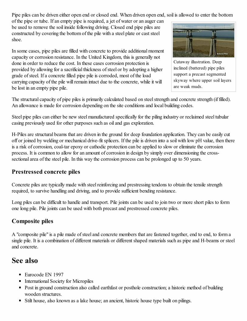
Cutaway illustration. Deep
inclined (battered) pipe piles
support a precast segmented
skyway where upper soil layers
are weak muds.
Pipe piles can be driven either open end or closed end. When driven open end, soil is allowed to enter the bottomof the pipe or tube. If an empty pipe is required, a jet of water or an auger canbe used to remove the soil inside following driving. Closed end pipe piles areconstructed by covering the bottom of the pile with a steel plate or cast steelshoe.
In some cases, pipe piles are filled with concrete to provide additional momentcapacity or corrosion resistance. In the United Kingdom, this is generally notdone in order to reduce the cost. In these cases corrosion protection isprovided by allowing for a sacrificial thickness of steel or by adopting a highergrade of steel. If a concrete filled pipe pile is corroded, most of the loadcarrying capacity of the pile will remain intact due to the concrete, while it willbe lost in an empty pipe pile.
The structural capacity of pipe piles is primarily calculated based on steel strength and concrete strength (if filled).An allowance is made for corrosion depending on the site conditions and local building codes.
Steel pipe piles can either be new steel manufactured specifically for the piling industry or reclaimed steel tubularcasing previously used for other purposes such as oil and gas exploration.
H-Piles are structural beams that are driven in the ground for deep foundation application. They can be easily cutoff or joined by welding or mechanical drive-fit splicers. If the pile is driven into a soil with low pH value, then thereis a risk of corrosion, coal-tar epoxy or cathodic protection can be applied to slow or eliminate the corrosionprocess. It is common to allow for an amount of corrosion in design by simply over dimensioning the cross-sectional area of the steel pile. In this way the corrosion process can be prolonged up to 50 years.
Prestressed concrete piles
Concrete piles are typically made with steel reinforcing and prestressing tendons to obtain the tensile strengthrequired, to survive handling and driving, and to provide sufficient bending resistance.
Long piles can be difficult to handle and transport. Pile joints can be used to join two or more short piles to formone long pile. Pile joints can be used with both precast and prestressed concrete piles.
Composite piles
A "composite pile" is a pile made of steel and concrete members that are fastened together, end to end, to form asingle pile. It is a combination of different materials or different shaped materials such as pipe and H-beams or steeland concrete.
See also
Eurocode EN 1997
International Society for Micropiles
Post in ground construction also called earthfast or posthole construction; a historic method of building
wooden structures.
Stilt house, also known as a lake house; an ancient, historic house type built on pilings.
Notes
1. ^ PDCA (https://secure.piledrivers.org/)
2. ^ Offshore Wind Turbine Foundations (http://offshorewind.net/Other_Pages/Turbine-Foundations.html), 2009-09-09, accessed 2010-04-12.
3. ̂a b Constructing a turbine foundation (http://www.hornsrev.dk/Engelsk/Opstillingen/uk-fundament.htm) HornsRev project, Elsam monopile foundation construction process, accessed 2010-04-12]
4. ^ Horns Revolution (http://www.modernpowersystems.com/story.asp?storyCode=2017033), Modern PowerSystems, 2002-10-05, accessed 2010-04-14.
5. ^ Lynn and Inner Dowsing description (http://www.greenenergytalkdirectory.org/library/Lynn-and-Inner-Dowsing.php)
6. ^ Handbook on Under-reamed and bored compaction pile foundation, Central building research institute Roorkee,Prepared by Devendra Sharma, M. P. Jain, Chandra Prakash
7. ^ Marshall, Brain. "How House Construction Works" (http://home.howstuffworks.com/home-improvement/repair/house6.htm). How Stuff Works. HowStuffWorks, Inc. Retrieved 4 April 2013.
8. ^ pwri.go.jp (http://www.pwri.go.jp/eng/ujnr/tc/g/pdf/22/22-8-1siel.pdf)
9. ^ dfi.org (http://www.dfi.org/pubdetail.asp?id=1725)
10. ^ "International Society for Micropiles" (http://www.ismicropiles.org). Retrieved 2007-02-02.
11. ^ terrasystemsonline.com (http://www.terrasystemsonline.com/services/stone-columns.html)
References
Fleming, W. G. K. et al., 1985, Piling Engineering, Surrey University Press; Hunt, R. E.,
Geotechnical Engineering Analysis and Evaluation, 1986, McGraw-Hill.
Coduto, Donald P. Foundation Design: Principles and Practices 2nd ed., Prentice-Hall Inc., 2001.
NAVFAC DM 7.02 Foundations and Earth Structures
(http://www.ce.washington.edu/~geotech/courses/cee523/manuals/NAVFAC72.pdf) U.S. Naval Facilities
Engineering Command, 1986.
Rajapakse, Ruwan., Pile Design and Construction Guide, 2003Tomlinson, P.J., Pile Design and Construction Practice, 1984
Stabilization of Organic Soils (http://ns.swedgeo.se/sd/pdf/SD-R3E.pdf)
Sheet piling handbook (http://www.thyssenkrupp-
bautechnik.com/fileadmin/download/pdf/eng/Rammprofile/SWHB_EBOOK_ENG.pdf), 2010
External links
Deep Foundations Institute (http://www.dfi.org)
International Construction Equipment (http://www.iceusa.com)
PDCA: Pile Driving Contractors' Association (http://www.piledrivers.org/)
ADSC: The International Association of Foundation Drilling (http://www.adsc-iafd.com)
International Society for Micropiles (http://www.ismicropiles.org)
Federation of Piling Specialists (UK) (http://www.fps.org.uk)Procedure of Installing Drilled Shaft (Bored Pile)
(http://www.foundationengineering.info/photo_galleries/12/drilled_shafts/)
Information on the analysis and design of sheeting piles (http://www.finesoftware.eu/geotechnical-
software/help/sheeting-design/analysis-of-sheet-pile-wall/)

The Uses of Sheet Piling (http://advancedsheetpiles.com/advanced-sheetpiles/use-of-sheetpiling)
Retrieved from "http://en.wikipedia.org/w/index.php?title=Deep_foundation&oldid=586556876"
Categories: Geotechnical engineering Structural engineering
This page was last modified on 17 December 2013 at 22:23.
Text is available under the Creative Commons Attribution-ShareAlike License; additional terms may apply.
By using this site, you agree to the Terms of Use and Privacy Policy.
Wikipedia® is a registered trademark of the Wikimedia Foundation, Inc., a non-profit organization.