Embed Size (px)
Citation preview

Deep drilling at Vostok station, Antarctica:history and recent events
N.I. VASILIEV,1 P.G. TALALAY,1 N.E. BOBIN,1 V.K. CHISTYAKOV,1 V.M. ZUBKOV,1
A.V. KRASILEV,1{ A.N. DMITRIEV,1 S.V. YANKILEVICH,1 V.Ya. LIPENKOV2
1St. Petersburg Mining Institute, 21 Line, 2, 199026 St Petersburg, RussiaE-mail: [email protected]
2Arctic and Antarctic Research Institute, 38 Beringa Street, 199397 St Petersburg, Russia
ABSTRACT. Deep drilling into the ice sheet at Vostok station, Antarctica, was started by specialists ofthe Leningrad Mining Institute (since 1991, St Petersburg State Mining Institute) in 1970. Five deep holeswere cored: hole No. 1 to 952m; hole No. 2 to 450.4m; hole No. 3G (3G-1, 3G-2) to 2201.7m; holeNo. 4G (4G-1, 4G-2) to 2546.4m; and hole No. 5G (5G-1) to 3650.2m depth. Drilling of hole 5G-1 isnot yet complete. The deep drilling at Vostok station has had successes and problems. All the deep holesat Vostok have undergone at least one offset drilling operation because of problems with lost drills.These deviations were made successfully using a thermal drilling technique. Several drilling records havebeen achieved at Vostok station. The deepest dry hole, No. 1 (952m), was made during Soviet AntarcticExpedition (SAE) 17 in 1972. The deepest fluid-filled hole, No. 5G-1, made by a thermal drill (TBZS-132), reached 2755m during SAE 38 in 1993. The deepest fluid-filled hole in ice, No. 5G-1, was drilledwith a KEMS-132 electromechanical drill and was stopped above Vostok Subglacial Lake at 3650.2mdepth during Russian Antarctic Expedition (RAE) 51 in 2006.
INTRODUCTIONOn 16 December 1957, during the International Geo-physical Year (1957/58), Vostok station (788280 S, 1068480 E;3488m a.s.l.) was established near the South GeomagneticPole, the point where the Earth’s magnetic dipole axiscrosses the Earth’s surface (Fig. 1). The South GeomagneticPole, like the South Magnetic Pole, changes through time,although more slowly. For example, in mid-1996 the SouthGeomagnetic Pole was situated at 798180 S, 1088300 E,approximately 100 km from Vostok. Since 1957, Vostokhas existed as a year-round research base of the ComplexAntarctic Expedition (CAE). In 1959 CAE was renamed theSoviet Antarctic Expedition (SAE). After the collapse of theUSSR, the Russian Federation assumed obligations relatingto the Antarctic Treaty, and on 7 August 1992, according toEdict No. 824 of the President of the Russian Federation, SAEbecame the Russian Antarctic Expedition (RAE).
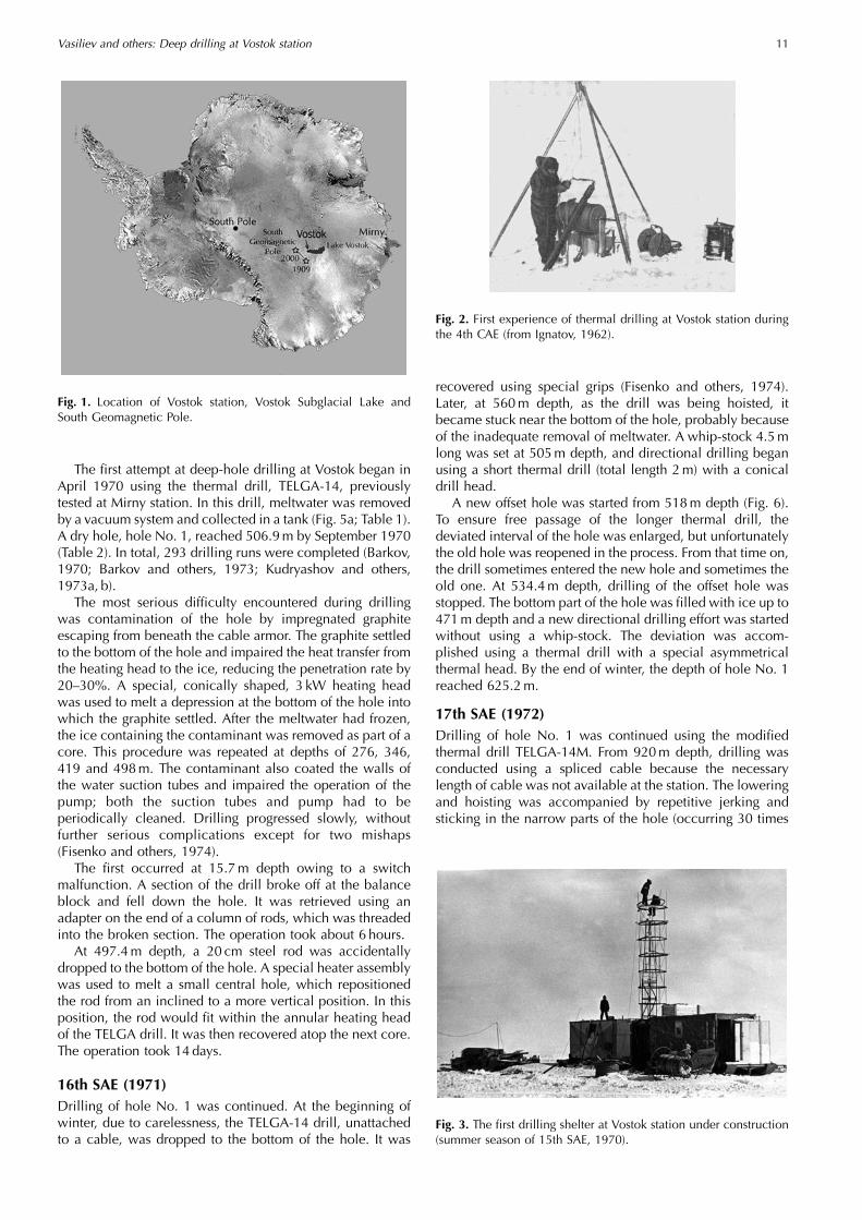
The first ice-drilling experience took place at Vostok in1958, when wintering-over personnel received a messagefrom the 4th CAE to start drilling into the ice sheet. Ninethermal-drill types were designed from makeshift materialand equipment found at the station. All of them were finallyfrozen in the ice. Nevertheless, four boreholes were drilledto a maximum depth of 52m (Fig. 2).
In 1963, a research agreement between the Arctic andAntarctic Research Institute (AARI) and two Moscow re-search institutes – the Moscow Mining Institute and theMoscow Institute of Radio-electronics and Mining Electro-mechanics – led to the design of a thermal ice-drillingsystem. In 1967 a collaboration between AARI and theLeningrad Mining Institute (LMI) led to development of thethermal coring drill for drilling in dry holes. Later, furtherimprovements were made under a new cooperative venturebetween AARI and LMI.
During the winter of 1969 (14th SAE) two test holes weredrilled near Mirny station and a 250m deep hole was drilledin 36 days at the 50 km mark of the Mirny–Vostok traverse. In1970, 12 years after the first experience, drilling at Vostokstation was conducted by LMI specialists. (In 1991 LMI wasrenamed the St Petersburg State Mining Institute (SPSMI)).Since 1970, five deep holes have been cored: hole No. 1 to952m; hole No. 2 to 450.4m; hole No. 3G (3G-1, 3G-2) to2201.7m; hole No. 4G (4G-1, 4G-2) to 2546.4m; and holeNo. 5G (5G-1) to 3650.2m depth.
In the mid-1990s, the existence of a large subglacial lakebeneath the Antarctic ice sheet (since named VostokSubglacial Lake – its south part underlies the station) wasrecognized (Ridley and others, 1993). Previously, theprimary objective of deep ice-core drilling at Vostok wasto acquire englacial geophysical data and a long ice core forstudies of past climate history. Now, the primary interest is tostudy the lake properties using the existing hole No. 5G-1.
In this paper, we recollect our successes and problemsincluding the reasons for accidents, some of which have notpreviously been published. Even for those that have beenpublished, descriptions of drilling operations have mostlybeen in Russian and not available for the English-readingscientific community. Most of the photographs are pub-lished here for the first time. The last part of the paper isdevoted to our plans for penetrating and sampling VostokSubglacial Lake.
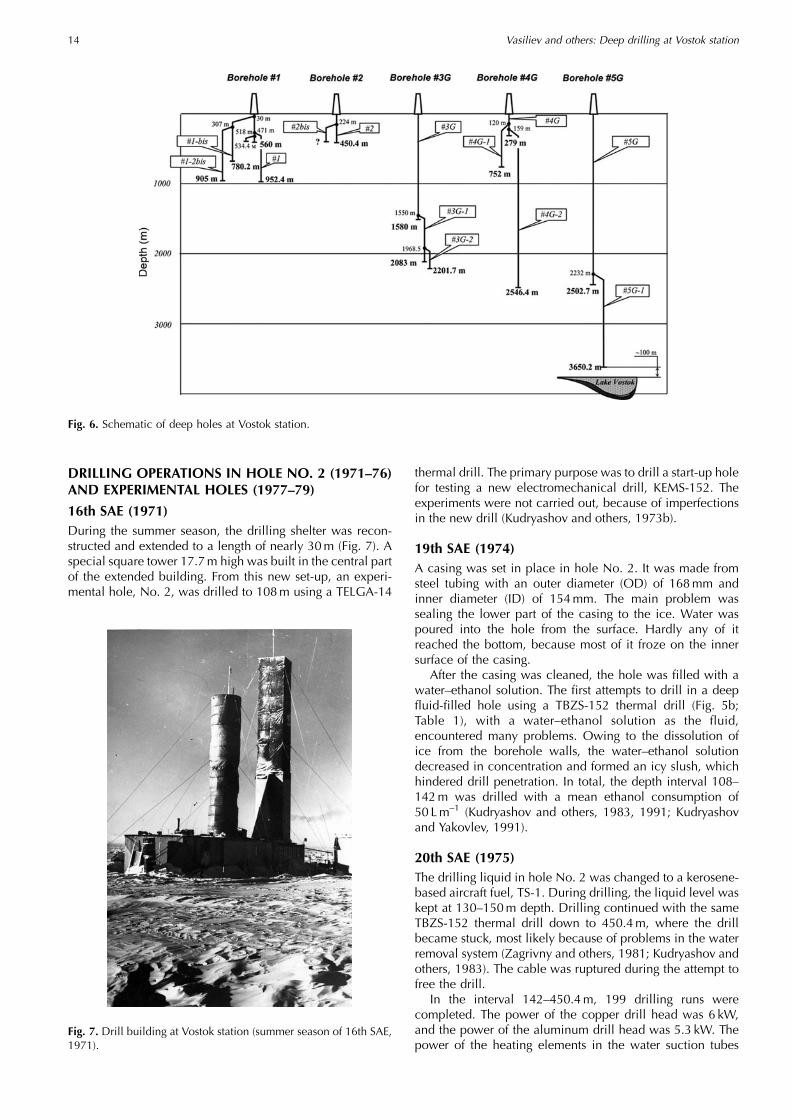
DRILLING OPERATIONS IN HOLE NO. 1 (1970–73)15th SAE (1970)In the summer season of the 15th SAE, the first drillingshelter was constructed on two steel sleds (Fig. 3), providinga work area measuring 15� 2.9�2.5m. A 9.7m roundtower, measured from the top of the hole, was constructed inthe center of the work area and wrapped in rubberized clothfor protection (Fig. 4).
Annals of Glaciology 47 2007
{Deceased.
10
The first attempt at deep-hole drilling at Vostok began inApril 1970 using the thermal drill, TELGA-14, previouslytested at Mirny station. In this drill, meltwater was removedby a vacuum system and collected in a tank (Fig. 5a; Table 1).A dry hole, hole No. 1, reached 506.9m by September 1970(Table 2). In total, 293 drilling runs were completed (Barkov,1970; Barkov and others, 1973; Kudryashov and others,1973a, b).
The most serious difficulty encountered during drillingwas contamination of the hole by impregnated graphiteescaping from beneath the cable armor. The graphite settledto the bottom of the hole and impaired the heat transfer fromthe heating head to the ice, reducing the penetration rate by20–30%. A special, conically shaped, 3 kW heating headwas used to melt a depression at the bottom of the hole intowhich the graphite settled. After the meltwater had frozen,the ice containing the contaminant was removed as part of acore. This procedure was repeated at depths of 276, 346,419 and 498m. The contaminant also coated the walls ofthe water suction tubes and impaired the operation of thepump; both the suction tubes and pump had to beperiodically cleaned. Drilling progressed slowly, withoutfurther serious complications except for two mishaps(Fisenko and others, 1974).
The first occurred at 15.7m depth owing to a switchmalfunction. A section of the drill broke off at the balanceblock and fell down the hole. It was retrieved using anadapter on the end of a column of rods, which was threadedinto the broken section. The operation took about 6 hours.
At 497.4m depth, a 20 cm steel rod was accidentallydropped to the bottom of the hole. A special heater assemblywas used to melt a small central hole, which repositionedthe rod from an inclined to a more vertical position. In thisposition, the rod would fit within the annular heating headof the TELGA drill. It was then recovered atop the next core.The operation took 14 days.
16th SAE (1971)Drilling of hole No. 1 was continued. At the beginning ofwinter, due to carelessness, the TELGA-14 drill, unattachedto a cable, was dropped to the bottom of the hole. It was
recovered using special grips (Fisenko and others, 1974).Later, at 560m depth, as the drill was being hoisted, itbecame stuck near the bottom of the hole, probably becauseof the inadequate removal of meltwater. A whip-stock 4.5mlong was set at 505m depth, and directional drilling beganusing a short thermal drill (total length 2m) with a conicaldrill head.
A new offset hole was started from 518m depth (Fig. 6).To ensure free passage of the longer thermal drill, thedeviated interval of the hole was enlarged, but unfortunatelythe old hole was reopened in the process. From that time on,the drill sometimes entered the new hole and sometimes theold one. At 534.4m depth, drilling of the offset hole wasstopped. The bottom part of the hole was filled with ice up to471m depth and a new directional drilling effort was startedwithout using a whip-stock. The deviation was accom-plished using a thermal drill with a special asymmetricalthermal head. By the end of winter, the depth of hole No. 1reached 625.2m.
17th SAE (1972)Drilling of hole No. 1 was continued using the modifiedthermal drill TELGA-14M. From 920m depth, drilling wasconducted using a spliced cable because the necessarylength of cable was not available at the station. The loweringand hoisting was accompanied by repetitive jerking andsticking in the narrow parts of the hole (occurring 30 times
Fig. 2. First experience of thermal drilling at Vostok station duringthe 4th CAE (from Ignatov, 1962).
Fig. 1. Location of Vostok station, Vostok Subglacial Lake andSouth Geomagnetic Pole.
Fig. 3. The first drilling shelter at Vostok station under construction(summer season of 15th SAE, 1970).
Vasiliev and others: Deep drilling at Vostok station 11

during one run). Nevertheless, the hole reached 952.4m inMay 1972, making it the deepest dry hole in ice (Korot-kevich and Kudryashov, 1976; Kudryashov, 1989). The finalrun occurred while the drill was being lowered to thebottom of the hole, when the winch-brake mechanismfailed. The drill dropped to the bottom of the hole followedby the cable, which eventually became detached from theclamp holding it to the winch drum and fell into the hole.The drill and cable were eventually left in the hole.
A new offset hole was started. A cylindrical piece of icewas dropped from the surface into the hole, but unfortu-nately it got stuck at 30m depth and efforts to dislodge itfailed (Fisenko and others, 1974). From this depth, a newoffset hole, hole No. 1-bis, was started and by the end of theyear reached 774m depth (Kudryashov and others, 1975,1977).
18th SAE (1973)The drilling in hole No. 1-bis was continued through theinterval 774–780.2m, at which point the hole becameinaccessible owing to an accident during hoisting. The
thermal head was stuck near the bottom and separated fromthe drill at 762m depth. The drill itself then became stuck at308m depth (Vartykyan and others, 1977). The main reasonfor the accident was the inexperience of the new team, whodid not recognize problems with the pumping of meltwaterat the bottom of the hole. Ultimately, this led to the drillbecoming stuck during hoisting (the drill profile ‘swelled’because of refrozen water on its surface) during one of thefirst runs carried out by the new drilling team of the18th SAE.
A new offset, hole No. 1-2bis, was started at 307m depthin hole No. 1-bis and reached 905m depth (Kudryashovand others, 1977, 1991). Further drilling in this hole wasstopped owing to the high risk of getting the drill stuck.Hole No. 1-2bis was available for several years for scientificobservations of temperature, deviation from the vertical, andwall deformation (Dmitriev and others, 1978).
Table 1. Main characteristics of drills
Type Max. depth drilled OD/ID of drill head Power of drill head Length of core barrel Length of drill Weight of drill
m mm kW m m kg
TELGA-14M 952 178/130 3.5 2.5 8.0 200TBZS-152M 2502 152/114 3.5 3.2 7.5 180TBZS-132 2755 132/95 3.0 3.0 7.2 120TBS-112VCh 2202 112/92 4.5 2.0 9.0 180KEMS-132(135) 3650 132–139/106–107 2.2� 1.5–3 7–12 180–240TBPO-132 – 132/– 4.0 – 3.0 100
Note: OD/ID: Outer diameter/inner diameter.�Power of driving motor.
Fig. 4. Schematic diagram of the first drilling shelter at Vostokstation: 1. electrical winch board; 2. control panel; 3. windowaperture; 4. oil furnace; 5. auxiliary hoist; 6. rig; 7. tower rings;8. drill positioned over the hole; 9. supporting framework; 10. benchand instruments; 11. fire prevention apparatus; 12. steel sled;13. hoist motor; 14. two-speed gear reducer; 15. main hoist;16. cable; 17. generator–motor system; 18. lathe; 19. collapsiblebalance block; 20. drill in the hole; 21. conductor.
Fig. 5. Thermal drills designed in Leningrad Mining Institute:(a) Thermal drill TELGA-14M: 1. cable; 2. centering springs; 3. vac-um pump; 4. central water suction tube; 5. water tank; 6. valve;7. water suction tubes; 8. core barrel; 9. core catcher; 10. thermalhead. (b) Thermal drill TBZS-152M: 1. cable; 2. cable termination;3. pump; 4. water tank; 5. central water suction tube; 6. connector;7. water suction tubes; 8. core barrel; 9. core catcher; 10. thermalhead. (c) Thermal drill TBS-112VCh: 1. cable; 2. cable termination;3. pump; 4. electrical transformers; 5. removable water tank;6. core barrel; 7. core catcher; 8. thermal head; 9. electrical lines;10. water suction tubes.
Vasiliev and others: Deep drilling at Vostok station12

Table 2. Deep drilling at Vostok station
Expedition No.(year)
Leaderof drilling team
HoleNo.
Drilling interval Type of drill Mean rateof penetration
Mean lengthof run
m mh–1 m
Hole No. 115 (1970) N.I. Barkov 1 0–506.9 TELGA-14 1.34 1.73
16 (1971) N.I. Slyusarev 1 506.9–560 TELGA-14 1.3 1.61 518–534.4 TELGA-14 1.3 1.61 471–625.2 TELGA-14 1.3 1.6
17 (1972) V.K. Chistyakov 1 625.2–952.4 TELGA-14M 1.2 2.31-bis 30–774 TELGA-14M 1.2 2.3
18 (1973) V.I. Kovalenko 1-bis 774–780.2 TELGA-14M 1.2 2.51-2bis 307–905 TELGA-14M 1.2 2.5
Hole No. 216 (1971) N.I. Slyusarev 2 0–108 TELGA-14M 1.3 1.6
19 (1974) B.S. Moiseev 2 108–142 TBZS-152 – –
20 (1975) R.N. Vostretsov 2 142–450.4 TBZS-152 2.6 1.55
21 (1976) V.N. Bakhtyukov 2-bis 224–? TBZS-152 – –
Hole No. 3G25 (1980) V.K. Chistyakov 3G 0–112 TELGA-14M – –
3G 112–1351 TBZS-152M 2.0 2.0
26 (1981) E.A. Zagrivny 3G 1351–1500 TBZS-152M 2.0 2.03G 1500–1580 TBS-112VCh 4.2 1.653G-1 1550–2004 TBS-112VCh 4.2 1.65
27 (1982) B.S. Moiseev 3G-1 2004–2083 TBS-112VCh 4.2 1.65
29 (1984) A.V. Krasilev 3G-2 1968.5–2040 TBS-112VCh 3.9 1.45
30 (1985) A.A. Zemtsov 3G-2 2040–2201.7 TBS-112VCh 3.7 1.55
Hole No. 4G28 (1983) A.M. Shkurko 4G 0–120 TELGA-14M 2.0 –
4G 120–279 TBZS-152M 1.9 2.18
29 (1984) A.V. Krasilev 4G – – – –
30 (1985) A.A. Zemtsov 4G-1 120–167 TELGA-14M – –4G-1 167–692 TBZS-152M 1.3 1.8
31 (1986) V.P. Lobanov, B.S. Moiseev 4G-1 692–752 TBZS-152M 1.3 2.34G-2 159–201 TELGA-14M – –4G-2 201–779 TBZS-152M 1.2 2.05
32 (1987) A.V. Krasilev 4G-2 779–1502 TBZS-152M 2.05 2.25
33 (1988) S.L. Mitin 4G-2 1502–2383 TBZS-152M 2.1 3.0
34 (1989) N.I. Vasiliev 4G-2 2383–2428.5 TBZS-152M 2.3 2.94G-2 2428.5–2546.4 KEMS-112 12.5 2.5
Hole No. 5G35 (1990) A.A. Zemtsov 5G 0–120 TELGA-14M 1.8 1.9
5G 120–1279.8 TBZS-152 2.1 2.9
36 (1991) A.V. Krasilev 5G 1279.8–2502.7 TBZS-152 2.3 3.0
37 (1992) B.S. Moiseev 5G-1 2232–2249.5 TBZS-132 2.0 1.05G-1 2249.5–2270.7 TBZS-132 2.0 2.0
38 (1993) V.K. Chistyakov 5G-1 2270.7–2755.3 TBZS-132 1.8 2.5
40 (1995) N.I. Vasiliev 5G-1 2755.3–3109 KEMS-132 (KEMS-135) 8.0 2.5
41 (1995/96)� N.I. Vasiliev 5G-1 3109–3350 KEMS-132 (KEMS-135) 8.0 2.2
42 (1997/98)� N.I. Vasiliev 5G-1 3350–3523 KEMS-132 (KEMS-135) 8.0 2.1
43 (1997/98)� N.I. Vasiliev 5G-1 3523–3623 KEMS-132 (KEMS-135) 8.0 1.8
51 (2005–06)� N.I. Vasiliev 5G-1 3623–3650.2 KEMS-132 (KEMS-135) 5.0 0.8
�Drilling was conducted during the austral summer only.
Vasiliev and others: Deep drilling at Vostok station 13
DRILLING OPERATIONS IN HOLE NO. 2 (1971–76)AND EXPERIMENTAL HOLES (1977–79)
16th SAE (1971)During the summer season, the drilling shelter was recon-structed and extended to a length of nearly 30m (Fig. 7). Aspecial square tower 17.7m high was built in the central partof the extended building. From this new set-up, an experi-mental hole, No. 2, was drilled to 108m using a TELGA-14
thermal drill. The primary purpose was to drill a start-up holefor testing a new electromechanical drill, KEMS-152. Theexperiments were not carried out, because of imperfectionsin the new drill (Kudryashov and others, 1973b).
19th SAE (1974)A casing was set in place in hole No. 2. It was made fromsteel tubing with an outer diameter (OD) of 168mm andinner diameter (ID) of 154mm. The main problem wassealing the lower part of the casing to the ice. Water waspoured into the hole from the surface. Hardly any of itreached the bottom, because most of it froze on the innersurface of the casing.
After the casing was cleaned, the hole was filled with awater–ethanol solution. The first attempts to drill in a deepfluid-filled hole using a TBZS-152 thermal drill (Fig. 5b;Table 1), with a water–ethanol solution as the fluid,encountered many problems. Owing to the dissolution ofice from the borehole walls, the water–ethanol solutiondecreased in concentration and formed an icy slush, whichhindered drill penetration. In total, the depth interval 108–142m was drilled with a mean ethanol consumption of50 Lm–1 (Kudryashov and others, 1983, 1991; Kudryashovand Yakovlev, 1991).
20th SAE (1975)The drilling liquid in hole No. 2 was changed to a kerosene-based aircraft fuel, TS-1. During drilling, the liquid level waskept at 130–150m depth. Drilling continued with the sameTBZS-152 thermal drill down to 450.4m, where the drillbecame stuck, most likely because of problems in the waterremoval system (Zagrivny and others, 1981; Kudryashov andothers, 1983). The cable was ruptured during the attempt tofree the drill.
In the interval 142–450.4m, 199 drilling runs werecompleted. The power of the copper drill head was 6 kW,and the power of the aluminum drill head was 5.3 kW. Thepower of the heating elements in the water suction tubes
Fig. 6. Schematic of deep holes at Vostok station.
Fig. 7. Drill building at Vostok station (summer season of 16th SAE,1971).
Vasiliev and others: Deep drilling at Vostok station14

was 120Wm–1; the power of the heating elements in thewater tank was 1.5 kW per meter of water column (Zagrivnyand others, 1980).
21st SAE (1976)A new offset hole, No. 2-bis, was started at 224m depth inthe original hole No. 2 but the drill became stuck again. Thefinal depth of hole No. 2-bis was not reported. According toour personal recollections, only a few runs in the new offsethole were made.
22nd SAE (1977)Experiments with a TBZS-152 thermal drill were continued.Two unnumbered holes with depths of 171 and 300m weredrilled. Drilling was difficult, and a few serious accidentsoccurred. Drilling at Vostok was suspended in order toimprove and test the technology of fluid-filled drilling. Suchexperimental drilling has been carried out on Vavilovglacier, Severnaya Zemlya archipelago, Russia, (Chistyakovand others, 1988) and, during the wintering of the 24th SAEat Gornaya base, at the 73 km mark of the Mirny–Vostokroute (Kudryashov and others, 1991).
DRILLING OPERATIONS IN HOLE NO. 3G(1980–86)
25th SAE (1980)The mobile drilling shelter, PBU-2, utilized for drilling atGornaya base was towed to Vostok (Fig. 8) and used fordrilling a new deep hole at Vostok station. The first 112m ofthe new hole, No. 3G (G is the first letter of the Russian wordglubokaya – ‘deep’), was drilled as an uncased, dry holeusing a TELGA-14M thermal drill. Below the firn–icetransition, the TBZS-152M thermal drill was used in a fluid-filled hole, the fluid consisting of aviation fuel TS-1 withdensifier CFC11. The hole was extended to 1351m by17 December 1980 (Kudryashov and others, 1983, 1984a, b,1991; Kudryashov, 1989; Kudryashov and Yakovlev, 1991).
26th SAE (1981)The drilling of hole No. 3G was continued with a TBZS-152M drill over the interval 1415–1500m. Beyond this
depth, the TBS-112VCh thermal coring drill (Fig. 5c; Table 1)was used. This drill used a high-frequency power supply,which reduced the dimensions of the electric transformerspositioned in the drill. At the surface, the power supply hada frequency of 2500Hz and voltage of 800–1000V. Passingthrough the cable, the electric voltage dropped to 700–900V. At the bottom, this primary voltage was reduced byelectric transformers to the voltage of 20–25V used inthe drill. The water tank was not heated. The meltwaterwas collected in a tank and frozen inside. At the surface,the tank was removed and replaced with an empty tank. Thecore barrel was made from a thick-walled tube, with thewater suction tubes and the electrical lines hidden withinthe wall.
The drilling rate was doubled to 3.5–4mh–1 over theTBZS-152M with 5 kW of power. After reaching 1580mdepth, owing to problems with the meltwater removalsystem, the drill became stuck near the bottom of the hole. Anew offset hole was started using another TBS-112VChthermal drill with a length of 7.1m at 1500m depth, and inthe interval 1550–1560m a full-diameter core was recov-ered (Zagrivny and Moiseev, 1988). The new offset hole wasdesignated hole No. 3G-1. A depth of 2004m was reachedby the end of the summer season (Kudryashov and others,1984a, 1991; Zagrivny and others, 1985; Kudryashov andYakovlev, 1991). Labeling of the ice core was kept as No. 3Gdown to 2083m, the end of hole No. 3G-1.
27th SAE (1982)In early 1982, hole No. 3G-1 was advanced to 2083m witha TBS-112VCh thermal drill (Zagrivny and others, 1985). Agenerator-room power-station fire on 12 April 1982 tragi-cally took the life of the chief mechanic and curtailed furtherdrilling (Kudryashov and others, 1991). On 26 December1982, another fire destroyed the drilling shelter PBU-2which housed the drilling complex for hole No. 3G, anddrilling was suspended.
29th SAE (1984)The mobile drilling complex PBU-3, which was transportedfrom Mirny during the 28th SAE, was installed above themouth of hole No. 3G (Fig. 9), replacing PBU-2 which hadbeen destroyed by fire. The drilling operations in hole
Fig. 8. The mobile drilling shelter PBU-2 towed to Vostok (summerseason of 25th SAE, 1980).
Fig. 9. The mobile drilling shelter PBU-3 installed above the mouthof hole No. 3G (summer season of 29th SAE, 1984).
Vasiliev and others: Deep drilling at Vostok station 15

No. 3G-1 were resumed with a TBS-112VCh thermal drill,but the lower part of the hole had closed in during the longperiod of inactivity. During the enlarging or reaming process,a new offset hole was accidentally started at 1968.5m depth.It was designated hole No. 3G-2 and was advanced to2040m (Kudryashov and others, 1991). Ice-core labeling wasNo. 3G-1 down to 2202m, the end of hole No. 3G-2.
30th SAE (1985)Drilling in hole No. 3G-2 was resumed. A TBS-112VChthermal drill reached 2201.7m in August 1985 for a newice-core drilling depth record (Kudryashov, 1989). Thedrilling was going on with continual enlarging of narrowingparts of the hole. Drill thermal heads were not properlyadapted to the high hydrostatic pressure of drilling fluids,which led to premature burning of heating elements. In total,nearly 75 thermal drill heads were used in the last interval,2040–2201.7m.
31st SAE (1986)The TBS-112VCh thermal drill was stuck in hole No. 3G-2during enlarging operations in the interval 1935–1943m(Kudryashov and others, 1991). Further activity in holeNo. 3G-2 was stopped.
DRILLING OPERATIONS IN HOLE NO. 4 (1982–89)27th SAE (1982)The construction of a new stationary drilling complex wasstarted for a new hole, No. 4G. It was built on two steel sledswith a 15m mast, and 4000m of a KG-95-180 type, seven-conductor armored cable (Kudryashov, 1989).
28th SAE (1983)The construction of a new drilling complex was finished by29 May 1983 (Fig. 10) and the new hole, No. 4G, wasstarted on 3 July. Drilling in holes No. 3G and No. 4Goverlapped by several years due to the efforts of two differentshifts. The 178mm diameter hole reached 120m using aTELGA-14M thermal drill. After the hole was filled withliquid, a TBZS-152M thermal drill was used to advance itto 279m by the end of the season, 12 February 1984(Kudryashov and others, 1991).
29th SAE (1984)Problems with the winch (the bolts of the winch drive-shaftcoupling failed) used for hole No. 4G resulted in the loss ofthe TBZS-152M drill at the previous season’s depth of 279m(Kudryashov, 1989). Further drilling operations in holeNo. 4G were curtailed.
30th SAE (1985)The lost drill in hole No. 4G was bypassed with an offset holeNo. 4G-1 started at 120m by a TELGA-14M thermal drill;drilling continued to 167m and then to 692m depth with aTBZS-152M thermal drill (Kudryashov and others, 1991).Unfortunately, the initial hole was not packed with ice beforedeviation, which caused many problems thereafter.
31st SAE (1986)Hole No. 4G-1 was advanced to 752m with the TBZS-152Mthermal drill. The old hole, No. 4G, was accidentally re-opened because of the absence of ice plug at the place ofdeviation. This made it impossible to return to holeNo. 4G-1, so a new offset hole, No. 4G-2, was started fromhole No. 4G at 159m. A depth of 779m was reached by26 December 1986. Owing to inadequate centering of thedrill, the inclination of hole No. 4G-2 reached 188 in the
Fig. 10. Schematic diagram of the drilling building utilized fordrilling of hole No. 4 and hole No. 5: 1. drilling shelter; 2. tower;3. winch; 4. cable; 5. control desk; 6. drill; 7. drill-handling device;8. d.c. generator; 9. electric motor; 10. worm reducer; 11 and12. pulleys; 13. geophysical winch.
Fig. 11. Mean daily core production in SAE-32: three pieces ofcore, each with a length near 3m.
Vasiliev and others: Deep drilling at Vostok station16

depth interval 500–600m (Kudryashov, 1989; Kudryashovand others, 1991).
32nd SAE (1987)Drilling in hole No. 4G-2 continued with a TBZS-152M drillto 1502m (Fig. 11). In order to reduce hole inclination, theinterval 779–936m was drilled with a shortened version ofthe TBZS-152M thermal drill (Kudryashov and others, 1991).The shortened version of the drill could penetrate with asmaller angle between axis of the drill and the vertical,allowing a reduction in the inclination.
33rd SAE (1988)The continuation of drilling in hole No. 4G-2 with the TBZS-152M drill passed 2213m by 1 November 1988, therebyexceeding the old record, and reached 2383m by the end ofthe season. The hole inclination did not exceed 48 (Kudrya-shov, 1989).
34th SAE (1989)Deep drilling of hole No. 4G-2 using the TBZS-152Mthermal drill was stopped at 2428.5m in April 1989 owingto hole closure caused by a deficiency in fluid pressuriza-tion. Attempts to increase the density of the hole fluid with ahigh-density additive were not fully successful.
In June 1989, drilling resumed with an electromechanicaldrill referred to as KEMS-112 or KEMS-132 (KEMS-135)
depending on ODs of the core barrel and the drill-headcutters (Fig. 12; Table 1). The upper part of the drill (motor-gear section, pump, cable termination, etc.), except theskates of the anti-torque sections, is the same in all versionsof the drill. The lower part of the drill (core barrel and chipchamber) of the KEMS-112 type is assembled from steeltubes with OD/ID of 108/99mm, and the KEMS-132 (KEMS-135) from tubes with OD/ID of 127/117mm. The drivemotor for either design was three-phase, 220V, with acapacity of 2.2 kW. A two-stage gear reducer lowered thespeed from 2800 rpm to 230 rpm. Testing had beenconducted in the Arctic prior to the drilling at Vostok.
In the first 20 runs, the length per run was <0.1m. Thedrill was stuck at 2431.7 and 2437.5m, but freed in 5 daysand 2 hours, respectively. After every 10–15m, the hole wasenlarged with a 135mm cutting head. At 2546.4m depth,drilling was interrupted for 16 days and a new 4000m longcable was installed. The drill became stuck on the first run,1m above the bottom. The operation was left for a year withtension on the cable (Vasil’yev and others, 1993; Kudrya-shov and others, 1994).
35th SAE (1990)The drilling complex was moved. A small shelter withpulling equipment was built above the mouth of holeNo. 4G. The drill was still stuck in the hole. During arecovery attempt, the cable failed near the surface inNovember 1990 (Kudryashov and others, 1994).
DRILLING OPERATIONS IN HOLE NO. 5G(1990–2006)35th SAE (1990)In January 1990 the drilling complex was moved 25m to thewest (Fig. 13 shows the drilling shelter as it appeared duringSAE-35). A new hole, No. 5G, was started on 20 February1990, using a TELGA-14M thermal drill to 120m depth in62 runs (Fig. 14). Beyond this depth, another thermal drill forfluid-filled holes, TBZS-152M, was used. A depth of1279.8m was achieved in 398 runs with the TBZS-152Mdrill by the end of the season, 29 January 1991 (Tchistiakovand others, 1994; Kudryashov and others, 1998a, b, 2002).
Fig. 12. KEMS-112 (KEMS-132) electromechanical drill: 1. cabletermination; 2. electric chamber; 3. hammer block; 4. anti-torquesystem; 5. pump; 6. electric drive motor; 7. reducer; 8. chipchamber including chip filter; 9. core barrel; 10. drill head.
Fig. 13. Drill building at Vostok station (summer season of 35thSAE, 1990).
Vasiliev and others: Deep drilling at Vostok station 17

36th SAE (1991)Drilling in hole No. 5G reached 2502.7m in December1991, with the TBZS-152M thermal drill completing 408runs. The round-trip time to the bottom of the hole and backincreased to 2.6 and 1.8 hours respectively, at 2500m depth.The inclination varied between 0.28 and 0.68 down to2000m, then increased gradually from 0.48 to 1.88 at2250m. At the end of December, the drill became stuck at2259m during a trip up-hole. The problem was caused byhole closure from insufficient fluid pressurization. Allattempts at recovery failed and the cable was pulled out ofthe top of the drill (Tchistiakov and others, 1994; Dmitrievand others, 1995; Kudryashov and others, 1998a, b, 2002).
37th RAE (1992)Densifier HCFC 141b was added to hole No. 5G, increasingthe fluid density to 900 kgm–3. About 35m of artificial corewas dropped on top of the stuck drill, creating a new holebottom at 2232m. A shortened version of the TBZS-132thermal drill, 6m long, was used to drill a new offset hole,No. 5G-1. From 2249.5m depth, drilling was continuedwith a TBZS-132 drill with a normal length of 8m, to2270.7m depth by the end of the winter and to 2341.8m bythe end of the summer season. The main differencesbetween the TBZS-132 and TBZS-152 thermal drills werethe OD and ID of the drill head and the tubing used for thecore barrel and water tank (Kudryashov and others,1998a, b).
38th RAE (1993)From August 1993, following the collapse of the USSR, icecoring and core research at Vostok station was conducted bya joint Russian–French–US project. The Russians maintainedthe station and conducted the drilling operations, the French
provided technical equipment and the Americans providedlogistical support. Since that time, the core has been dividedbetween the three partners to the agreement.
Hole No. 5G-1 reached 2755.3m depth with the TBZS-132 drill. The depth was a new record for thermal drilling inice. From 18 September 1993, drilling ceased because thesupply of drilling fluid was exhausted (Kudryashov andothers, 1998a, b, 2000, 2002).
39th RAE (summer season 1993/94)During the summer season, the upper part of hole No. 5G-1was enlarged from 180 to 220mm using an electromech-anical reaming technique. The hole was cased with fiberglasstubing and, using a thermal shoe at the bottom of the casing,it was sealed at 120m depth so that hole fluid could beretained throughout the permeable zone. The OD/ID of thecasing tubes was 179/165mm. The OD of the connectingcouplings of the 6m long sections was 215mm. It wasdiscovered, however, that fluid could only be maintained toa maximum height of 66m below the surface, owing to aleak at an uncertain location (Kudryashov and others, 2000,2002). On 10 February 1994, Vostok station was temporarilyclosed for the winter for logistical and economic reasons.
40th RAE (1995)On 22 November 1994, the traverse from Mirny reachedVostok, and on 27 November the station was fully reopened.Drilling operations in hole No. 5G-1 were resumed. First, tocompensate for the ice overburden pressure, the density ofthe drilling fluid in the hole was increased. Then the holewas enlarged between 2200 and 2755m from 134 to139mm in diameter with an electromechanical reamer tofacilitate lowering and raising the drill. Drilling began withthe KEMS-132 electromechanical drill in February 1995 andreached 3109m depth in September 1995, when the drillingwas stopped because all of the densifier supply had beenconsumed. An average drilling run of 2.8m was achieved,but beyond 2930m the length of the drilling runs decreaseddramatically because of sticking and jamming of the drill(Kudryashov and others, 1998a, b, 2000, 2002). The tem-perature in the hole at 2930m depth was near –208C
Fig. 14. One of the first cores recovered by TELGA-14M thermaldrill in hole No. 5G.
Fig. 15. Temperature profile in the lower part of hole No. 5G.
Vasiliev and others: Deep drilling at Vostok station18

(Fig. 15), too cold to consider ‘warm ice’ as the main reasonfor complications. Partially our problems can be explainedby changing ice properties, in particular changing ice crystalsize (see below).
41st RAE (summer season 1995/96)A supply of the densifier HCFC 141b was delivered to thestation by C-130 aircraft from the US McMurdo Station, anda large amount of densifier was added to hole No. 5G-1 toraise the fluid density. Drilling was continued, and reached3350m by January 1996 using the KEMS-132 drill with acutter diameter of 135mm. The hole was enlarged to137mm every 25–30m. Increasing difficulties with chipcollection in the warmer ice after 3000m resulted in shortercores and the eventual stoppage of drilling (Kudryashov andothers, 1998a, b, 2000, 2002). A traverse consisting of16 vehicles started from Mirny to Vostok on 12 November1995, but mechanical problems with the vehicles forced adecision to cancel the traverse at the 645 km mark. For thefirst time in Soviet and Russian Antarctic expeditions, atraverse failed to reach Vostok station. On 24 January 1996all the people were evacuated by C-130 aircraft and Vostokstation was closed down again. Future drilling operationswere to be reduced to short Antarctic summer seasons.
42nd RAE (summer season 1996/97)Vostok station was reopened and the drilling of holeNo. 5G-1 was resumed with the KEMS-132 electromech-anical drill. The drill head was equipped with special shoesto limit the pitch of the cutters, which allowed drillingoperations to resume. However, at the end of this season thedecrease in the length of the drilling runs (up to a completestoppage of coring) reoccurred. It is worth noting that in thetwo latter cases the stoppage was not associated with jam-ming of the drill head. Drilling efficiency was reduced dra-matically, and sticking of the drill head due to the presence of
ice chips at the hole bottom was occurring immediately afterthe beginning of a drilling run. Nevertheless, hole No. 5G-1reached 3523m by the end of the season at the end ofJanuary 1997 (Kudryashov and others, 2002).
43rd RAE (summer season 1997/98)Despite the improvements that have been brought into thedesign of some units of the drill, at the beginning of the 43rdRAE season the drilling was unstable again. Only after certainchanges in the geometry of the cutter, aimed at decreasingsticking of the ice chips to the drill head, could the drilling becontinued. To prevent icing on drill-head cutters, the clear-ance angle was increased to 158; in addition, the cutters andthe body of the drill head were covered with a thin Teflonlayer. These measures significantly increased the efficiency ofice destruction and chip removal from the hole bottom. As aresult, ice coring during the 43rd RAE season was performedin the routine mode of operations. Drilling was stopped at3623m in January 1998, about 130m above Vostok Sub-glacial Lake (Kudryashov and others, 2002).
During this drilling season, at 3538m depth the drillpassed from meteoric ice into accretion ice which formed byfreezing of the subglacial lake. There was no visible changein drilling mode except the appearance of oversize icepieces at the bottom of the hole (see next subsection).
Between 1998 and 2005, borehole geophysical measure-ments were performed.
51st RAE (summer season 2005/06)After 8 years, hole No. 5G-1 was reopened for drilling. Atthe beginning of the summer season, the drilling equipmentand the hole itself were carefully inspected. On 31 Decem-ber 2005, the first productive run was made by theelectromechanical drill KEMS-135, and 0.5m of new corewas recovered. The new geometry of cutters for drilling of‘warm ice’ was tested: the bottom-side form of the cuttershad a dihedral shape, which allowed the clearance angle tobe increased up to 308. This gave stabilization to the drillingprocess. As a result, hole No. 5G-1 was deepened to3650.2m, with an average core length of 0.7–0.8m per run(Fig. 16). On 25 January 2006, the seasonal operations atVostok ceased.
The hole diameter was measured by a special boreholelogger of lever type with a precision of 0.2mm. Thediameter change over time was insignificant and lay in therange of measurement accuracy (Fig. 17). The drilling-fluid
Fig. 16. Drilling team of the 2005/06 summer season with recordcore from 3650m depth. From left to right: A. Krasilev, A. Ekaikin,V. Zubkov, A. Dmitriev and N. Vasiliev.
Fig. 17. Diameter of hole No. 5G-1 versus depth at different times:25 January 1998 (thick solid line); 29 December 1999 (dotted line);and 23 January 2006 (thin solid line).
Vasiliev and others: Deep drilling at Vostok station 19

pressure in the hole was measured, and the pressuredifference on the hole walls was estimated (Fig. 18). Thepressure difference at depths close to the hole bottom is nearzero, which indicates satisfactory compensation of the iceoverburden pressure. The liquid level is at 95m depth; theaverage fluid density is 928 kgm–3.
Drilling performance in ‘warm ice’Electromechanical drilling of ‘warm ice’ is characterized bysudden losses of drilling progress, which are caused by therapid gluing together of ice cuttings forming ice spots andrings on the surface of the drill equipment (especially nearthe drill head). This blocks the fluid circulation, and thenormal drilling process is stopped. If the drilling is con-tinued, there is a high risk of getting the drill stuck. Thiseffect was noticed in all recent drilling projects in Greenland(NorthGRIP) and Antarctica (Dome C, Dronning Maud Landand Dome F).
The first problems that could be connected with thepeculiar properties of ‘warm ice’ appeared in hole No. 5G-1at depths near 3000m. The instability of drilling progres-sively increased with depth. In particular, unexpectedjamming of the drilling head often occurred even at lowdrilling pressures, that is, at penetration speeds of about1mh–1 or less. This was accompanied by significantly shorterdrilling runs. At depths below 3480m, the efficiency ofdrilling was reduced dramatically, and sticking of the drillhead due to the presence of ice chips at the bottom of thehole occurred immediately after beginning a drilling run.
We explain our problems in terms of the changing iceproperties, in particular by changes of ice crystal size andice surface structure. In Figure 19, two plots – run length and
crystal size vs depth – are combined (data on ice crystal sizeare from Lipenkov and Barkov (1998) and Lipenkov andothers (2000)). The correspondence between these plots isclearly visible: increasing ice crystal size leads to decreasingrun length. Certain improvements were brought into thedesign of the drill head and chips chamber that allowed thedrilling operations to proceed, but the tendency towarddecreasing run length continued.
The ice cuttings of fine-grained ice with crystal sizes lessthan 5mm consist of chips with dimensions of 1–2mm andmore. The cutting process of the coarse-grained ice isdifferent: the dimensions of the ice cuttings are much less,not exceeding 0.5mm. At the same time, many very smallchips like ice fines were formed. The fine chips easilyplugged the filter in the chips chamber, sharply increasingthe hydraulic resistance in the drill circulation system anddecreasing the fluid flow rate. The drop in the flow ratecaused ice plugs to form in the most critical places of thedrill, i.e. near the cutters and the drill head.
This situation is exacerbated by water appearance on theice surface. According to the theory of Fletcher (1970), onthe surface of ice with a temperature of –68C the quasi-watery layer with a thickness of near 10 A (10–9m) appearsinstantaneously, and at temperatures near 08C the thicknessof the layer increases to several hundred angstroms.Fletcher’s conclusions were made for ice under atmosphericpressure. Taking into account the depression of the icemelting point under pressure, we can estimate the change inadhesion properties of the ice starting from depths near3000m.
Another problem with coarse-grained-ice drilling was theformation of oversize pieces of ice that were split off thecore while the core was broken from the bottom by corecatchers. Higher in the hole, such ice pieces were fine-grained and easily broken by drill-head cutters. Breaking thecoarse-grained ice pieces required a considerably higherforce impact. Ice pieces with dimensions larger than clearopenings cannot be destroyed by the cutters, and so initiateice-plug formation in the space between two cutters(Fig. 20). Even though the two other openings of the drillhead were still unblocked, eventually the penetrationstopped (our experience showed that it was possible to drillno more than 50–100mm having such an ice plug in theopening between cutters).
We can imagine the following interaction modes betweencutters and oversize pieces of ice. If the oversize ice piecesenter the opening of the drill head, it is impossible topenetrate at all, even at a cutter load equal to the drill weight
Fig. 19. Length of run and ice crystal size versus depth in holeNo. 5G-1.
Fig. 18. Pressure difference on the walls of hole No. 5G-1.Fig. 20. Ice pieces and compressed cuttings between drill-headcutters.
Vasiliev and others: Deep drilling at Vostok station20

(Fig. 21a). To avoid such a mode it is necessary to limit thespace between cutters with the help of a fixed stop installedbetween cutters. The size A (Fig. 21b) should be less than theclearance between the core and the inner surface of the corebarrel. In this case, the destruction of oversize pieces of iceshould proceed as shown in Figure 21b–e. The oversizepieces of ice cannot enter the opening of the drill head andso begin to be cut by the cutters. The ice cuttings producedlook like thin plates with a width equal to cutter width and athickness of a few millimeters. During experimental drillingwith a modified drill head, we have repeatedly found suchice plates in the chips chamber.
The width of these plates is not small enough for them topass through the clearances of the drill circulation system.To decrease the width of such ice plates, special grooveswere made in the bottom side of the cutters, dividing theedge of the cutters into two working areas (Fig. 22).
PLANNING PENETRATION AND SAMPLINGOF VOSTOK SUBGLACIAL LAKESince 1998, a technique for the continued penetration ofhole No. 5G-1 to Vostok Subglacial Lake has been studied(Verkulich and others, 2002). We propose to access the lakeand sample the water in three stages, as follows (Fig. 23).
The first stage includes an additional deepening of holeNo. 5G-1 to a depth near 3720m, leaving about a 30mthick ice layer to prevent contamination of the lake by thedrilling fluid. This can be accomplished with electromech-anical drill KEMS-135, which has been successfully em-ployed here. Then a new, ecologically friendly liquid(silicone oil) is delivered to the hole bottom by a specialtanker. It is anticipated that this hydrophobic liquid, beingheavier than the drilling fluid and lighter than water, will
create a 100m thick ‘buffer layer’ in the bottom part of thehole. The hydrostatic pressure at the bottom of holeNo. 5G-1 should be slightly lower than the overburden icepressure.
The second stage is drilling up to the ice–water interface.This will be carried out by thermal drill TBPO-132 in oneoperation. Two versions of thermal drill TBPO-132 (withoutcontainer for subglacial water and with it) are shownschematically in Figure 24. At the instant the tip of the
Fig. 22. Modified cutter.
Fig. 23. Scheme of penetration and sampling of Vostok SubglacialLake.
Fig. 21. Scheme of interaction between cutters and oversize piecesof ice.
Fig. 24. Scheme of thermal drill TBPO-132: (a) without sampler;and (b) with sampler.
Vasiliev and others: Deep drilling at Vostok station 21

thermal head touches the ice–water interface, a specialpenetration gauge gives a signal to the surface and the packerof the thermal drill is automatically turned on. The packer isneeded for separation of the hole and lake at the instant ofpenetration.
If the special sterilized container is used, the valve isopened and the container is filled by subglacial water. Whenthe container is full, the valve is closed. After estimating theactual difference between the pressures in the hole and inthe lake and maintaining that pressure difference in therange 3–4bar, the packer is turned off and the water from thelake is allowed to enter the hole (this moment is shown inFig. 23, stage II). The thermal drill TBPO-132 will be pulledup. It should be possible to allow lake water to enter into thehole to a height of 30 or 40m and to freeze.
The third and last stage will be conducted afterconfirming that the freezing in the hole is finished. Coringof the frozen lake ice can then be done with the electro-mechanical drill KEMS-135 down to 10–15m above the ice–water interface.
The project ‘Basis and Design of an EnvironmentallyClean Penetration to Lake Vostok, Antarctica’, prepared bySPSMI and AARI, was approved by the Ministry of NatureResources of the Russian Federation (Order No. 257,26 March 2001). The Russian project for the penetration toVostok Subglacial Lake was presented to the 26th AntarcticTreaty Consultative Meeting in Madrid, Spain, in June 2003.The project for the penetration to Vostok Subglacial Lake hasstarted. The distance between the hole bottom and the ice–lake interface is near 100m now. In the 2006/07 summerseason and the winter of 2007, additional drilling of the holeto a depth of near 3720m is planned.
ACKNOWLEDGEMENTSThe report is dedicated to all ‘miners’ who tirelessly spent somany years and expended so much effort to further the causeof glaciology. From the very beginning, Vostok drilling wasled by B.B. Kudryashov, who passed away on 12 April 2002.Since 1999, deep drilling at Vostok station has been carriedout within the framework of the Federal Targeted Program(FTP) ‘World Ocean’, subprogram ‘Antarctica’, project 4‘Deep ice coring, paleoclimate research and Subglacial LakeVostok exploration’. The authors thank H. Ueda for help inorganizing and correcting material regarding the Vostokdrilling. We also thank C.R. Bentley for very constructiveand pertinent remarks and for editing this paper.
REFERENCESBarkov, N.I. 1970. Predvaritel’nie rezul’taty bureniya lednikovogo
pokrova na stantsii Vostok [Preliminary results of ice drilling atVostok Station]. Inf. Byull. Sov. Antarkt. Eksped., 8(2), 58–60. [InRussian.]
Barkov, N.I., N.Ye. Bobin and G.K. Stepanov. 1973. Burenieskvazhiny v lednikovom pokrove Antarktidy na stantsii Vostok v1970 g [Drilling on the ice sheet of Antarctica at Vostok Stationin 1970]. Inf. Byull. Sov. Antarkt. Eksped., 8(7), 376–379. [InRussian.]
Chistyakov, V.K., A.M. Shkurko, A.A. Zemtsov, N.I. Vasiliev andS.P. Solov’ev. 1988. Eksperimental’niye burobie raboti naSevernoi Zemle v 1975–1985 gg [Experimental drilling opera-tions at Severnaya Zemlya in 1975–1985]. In Geograficheskiei glyatsiologicheskie issledovaniya v polarnikh stranakh
[Geographical and glaciological investigations in polar regions].Leningrad, Gidrometroizdat, 33–42. [In Russian.]
Dmitriev, D.N., R.N. Vostretsov and I.A. Petukhov. 1978. Defor-matsiya stenok glubokoy skvazhiny v antarkticheskom ledniko-vom pokrove na stantsii Vostok [Deformation of the sides of adeep borehole in the Antarctic ice cover at Vostok Station].Byull. Sov. Antarkt. Eksped., 98, 53–57. [In Russian.]
Dmitriev, A.N., V.M. Zubkov, A.V. Krasilev, N.G. Menshikov andV.M. Pashkevich. 1995. Rezul’taty burenia skvazhiny 5G nastantsii Vostok v 1991 g [Results of drilling hole 5G at VostokStation in 1991]. Mater. Glyatsiol. Issled. 79, 174–176. [InRussian.]
Fisenko, V.F., N.E. Bobin, G.K. Stepanov, N.I. Slyusarev, G.N. Solo-v’ev and V.K. Chistyakov. 1974. Oslozhneniya i avarii priglubokom burenii-protaivanii, ih likvidatsiya i preduprezhdenie[Complications and accidents during deep thermal-drilling, theirremoval and prevention]. Antarkt. Dokl. Kom. 13, 161–166. [InRussian.]
Fletcher, N.H. 1970. The chemical physics of ice. Cambridge,Cambridge University Press.
Ignatov, V.S. 1962. God na polyuse kholoda [A year on the pole ofcold]. Moscow, Geografgiz. [In Russian.]
Korotkevich, Ye.S. and B.B. Kudryashov. 1976. Ice sheet drilling bySoviet Antarctic Expeditions. In Splettstoesser, J.F., ed. Ice-coredrilling. Lincoln, NB, University of Nebraska Press, 63–70.
Kudryashov, B.B. 1989. Soviet experience of deep drilling inAntarctica. In International Symposium on Mining in the Arctic,17–19 July 1989, Fairbanks, Alaska. Proceedings. Rotterdam,A.A. Balkema, 113–122.
Kudryashov, B.B. and A.M. Yakovlev. 1991. Drilling in thepermafrost. Rotterdam, A.A. Balkema. (Russian TranslationSeries 84.)
Kudryashov, B.B., V.F. Fisenko, G.K. Stepanov and N.E. Bobin.1973a. Opyt burenya ledyanogo pokrova Antarktidy [Experienceof drilling in Antarctic Ice Sheet]. Antarkt. Dokl. Kom. 12, 145–152. [In Russian.]
Kudryashov, B.B., N.Y. Bobin, N.I. Slyusarev, N.I. Stepanov,V.F. Fisenko and V.K. Chistyakov. 1973b. Teoriya i praktikabureniya-protaivaniya v Antarktide [Theory and practice ofthermal drilling in Antarctica]. Mater. Glyatsiol. Issled. 22, 71–77. [In Russian with English summary.]
Kudryashov, B.B., V.K. Chistyakov and V.G. Vartykyan. 1975.Rezul’taty issledovanyi I razrabotok po glubokomu bureniyu-protaivaniyu vo l’dah Antarktidy [Investigation and designingresults of deep drilling–melting in ice of Antarctica]. InFysicheskie protsessy gornogo proizvodstva. Mezhvuzovskysbornik, Vipusk 1 [Physical processes in mining. Inter-institutioncollection of articles, Issue 1]. Leningrad, Leningradskyi GornyiInstitut, 111–116. [In Russian.]
Kudryashov, B.B., V.K. Chistiakov and N.E. Bobin. 1977. Burenieskvazhin teplovim sposobom v lednikovom pokrove Antarktidy[Borehole thermodrilling in Antarctic ice sheet]. Moscow,VIEMS. [In Russian.]
Kudryashov, B.B., K.V. Chistyakov and V.A. Morev. 1983. Burenielednikovogo pokrova Antarktidy teplovym sposobom [Thermaldrilling in Antarctic ice sheet]. In 25 let Sovetskoi AntarkticheskoiEkspeditsii [25th Anniversary of the Soviet Antarctic Expedition].Leningrad, Gidrometeoizdat, 138–149. [In Russian.]
Kudryashov, B.B., K.V. Chistyakov, E.A. Zagrivny and V.Ya. Lipenkov.1984a. Preliminary results of deep drilling at Vostok Station,Antarctica 1981–1982. CRREL Spec. Rep. 84-34, 123–124.
Kudryashov, B.B., V.K. Chistyakov and N.Y. Bobin. 1984b.Problema bureniya glubokikh skvazhin v tsentral’nykh rayonakhAntarktidy [Problem of drilling deep boreholes in the centralregions of Antarctica]. Mater. Glyatsiol. Issled. 51, 168–172. [InRussian with English summary.]
Kudryashov, B.B., V.K. Chistyakov and V.S. Litvinenko. 1991.Burenie skvazhin v usloviah izmenenia agregatnogo sostoyanyagornikh porod [Drilling in conditions of rock aggregatechanges]. Leningrad, Nedra. [In Russian.]
Vasiliev and others: Deep drilling at Vostok station22

Kudryashov, B.B., N.I. Vasiliev, and P.G. Talalay. 1994. KEMS-112electromechanical ice core drill. Mem. Natl. Inst. Polar Res., 49,Special Issue, 138–152.
Kudryashov, B.B., V.K. Chistyakov, N.I. Vasiliev and A.B. Volkov.1998a. Burenie i issledovanie glubokoy skvazhiny na stantsii[Drilling and investigation of a deep hole at Vostok Station].Antarkt. Dokl. Kom. 34, 73–78. [In Russian.]
Kudryashov, B.B. and 6 others. 1998b. Drilling equipment andtechnology for deep ice coring in Antarctica. In Hall, J., ed.Proceedings of Seventh Symposium on Antarctic Logistics andOperations, 6–7 August 1996, Cambridge, UK. Cambridge,British Antarctic Survey, 205–210.
Kudryashov, B.B., N.I. Vasiliev, V.M. Zubkov, A.V. Krasilev,V.V. Nikishin and V.K. Chistyakov. 2000. O burenii glubokoyskvazhiny na stantsii Vostok v Antarktide [Drilling of the deephole at Vostok Station in Antarctica]. In IV MezhdunarodnySimposium po bureniyu skvazhin v oslozhennikh usloviayh:Sbornik dokladov [Fourth International Symposium on Drillingunder Complicated Conditions: Collection of Reports]. StPetersburg, SPSMI, 7–11. [In Russian.]
Kudryashov, B.B. and 9 others. 2002. Deep ice coring at VostokStation (East Antarctica) by an electromechanical drill. Mem.Natl. Inst. Polar Res., 56, Special Issue, 91–102.
Lipenkov, V.Ya. and N.I. Barkov. 1998. Stroyeniye Antarktiches-kogo lednikovogo pokrova po rezul’tatam glubokogo bur-eniya na stantsii Vostok [Internal structure of the Antarcticice sheet as revealed by deep core drilling at Vostokstation]. In Izuchenie ozera Vostok – nauchnye zadactu itekhnologii. Mezhdunarodnoe soveschanie. Tezisy dokladov.[Lake Vostok study: scientific objectives and technologicalrequirements. International workshop. Abstracts]. St Peters-burg, Arctic and Antarctic Research Institute, 31–35. [InRussian.]
Lipenkov, V.Y., N.I. Barkov and A.N. Salamatin. 2000. Istoriyaklimata i oledeneniya Antarktidy po rezul’tatam izucheniyaledanogo kerna so stantsii Vostok [The history of climate andglaciation of Antarctica from results of the ice core study atVostok Station]. Probl. Arkt. Antarkt., 72, 197–236. [In Russianwith English summary.]
Ridley, J.K., W. Cudlip and S.W. Laxon. 1993. Identification ofsubglacial lakes using ERS-1 radar altimeter. J. Glaciol., 39(133),625–634.
Tchistiakov, V.K., A. Kracilev, V.Y. Lipenkov, J.P. Balestrieri, C. Radoand J.R. Petit. 1994. Behaviour of a deep hole drilled in ice atVostok station. Mem. Nat. Inst. Polar Res., 49, Special Issue,247–255.
Vartykyan, V.G., V.I. Kovalenko and B.S. Moiseev. 1977. Opytiskrivleniya skvazhin v usloviyah Antarktidy [Experience ofborehole deviation in Antarctica]. Inf. Byull. Sov. Antarkt.Eksped., 96, 24–25. [In Russian.]
Vasil’yev, N.I., B.B. Kudryashov, P.G. Talalay and V.K. Chistyakov.1993. Core drilling by electromechanical drill. Polar Rec.,29(170), 235–237.
Verkulich, S.R. and 11 others. 2002. Proposal for penetration andexploration of subglacial Lake Vostok, Antarctica. Mem. Natl.Inst. Polar Res., 56, Special Issue, 245–252.
Zagrivny, E.A. and B.S. Moiseev. 1988. Oslozhneniya i metody ihustraneniya pri burenii glubokoi skvazhiny na stantsii Vostok[Complications and methods of their removal during deep dril-ling at Vostok station].Zapiski Leningrad.Gorn. Inst., 116, 87–93.
Zagrivny, E.A., A.A. Zemtsov, R.N. Vostretsov and A.M. Shkurko.1980. Eksperimental’noe burenie skvazhiny, zalitoi nezamer-zayushchei zhidkost’yu [Experimental drilling of a hole filled bya non-freezing liquid]. Inf. Byull. Sov. Antarkt. Eksped., 100,119–123. [In Russian.]
Zagrivny, E.A., A.A. Zemtsov, Yu.B. Kononov, B.S. Moiseev,P.A. Petukhov and A.M. Shkurko. 1981. Opyt byreniya-plavleniya skvazhin, zalitkh nezamerzayushchey zhidkostyu, vAntarktike i Arktike [Experience of drilling by melting of holesfilled with a non-freezing liquid in Antarctica and the Arctic].Zapiski Leningrad. Gorn. Inst., 86, 79–83. [In Russian.]
Zagrivny, E.A., B.S. Moiseev and A.M. Shkurko. 1985. Rezul’tatypolevih ispytanyi vysokochastotnogo termoburovogo kompleks-ka TBS-112VCh pri burenyi glubokoi skvazhiny v nizkotemper-aturnom lednikovom pokrove (stantsiya Vostok) [Results of fieldtests of a high frequency thermal drill TBS-112VCh by drilling adeep hole in a low-temperature ice sheet (Vostok station)].Zapiski Leningrad. Gorn. Inst., 105, 103–107. [In Russian.]
Vasiliev and others: Deep drilling at Vostok station 23


![Thermobaric Conditions at Ice-Water Interface in Subglacial Lake Vostok … · Vostok station can be taken equal to 923 kg/m3 [20]); g is the acceleration of gravity, 9.81 m/s2; Z](https://img.pdfslide.us/doc/110x75/5f0916e37e708231d4252e1a/thermobaric-conditions-at-ice-water-interface-in-subglacial-lake-vostok-vostok-station.jpg)