Embed Size (px)
Citation preview

Dedicated Links Connectivity Specifications
V0.2
Author 4CB
Version V0.2
Date 30/03/2012
All rights reserved. Reproduction for educational and non-commercial purposes is permitted provided that the source is acknowledged.

Dedicated Links Connectivity Specifications
Page 2 on 76
1. INTRODUCTION 4
1.1. DESCRIPTION OF THE NETWORK CONNECTION TO T2S............................................................ 4
1.2. T2S TECHNICAL ENVIRONMENTS ........................................................................................ 5
1.3. THE COMMUNICATION MODES ............................................................................................ 6
1.4. OVERALL COMMUNICATION SCHEMA AND DATA EXCHANGE SCENARIO ........................................ 7
2. THE NETWORK CONNECTIVITY FOR DEDICATED LINKS 9
3. APPLICATION TO APPLICATION (A2A) 10
3.1. T2S APPLICATION TO APPLICATION COMMUNICATION INTERFACE.......................................... 10 3.1.1. WMQ DESCRIPTION .........................................................................................................................10
3.2. T2S QUEUE MANAGER CONFIGURATION OVERVIEW.............................................................. 11
3.3. THE CONNECTION .......................................................................................................... 13 3.3.1. SERVER-SERVER WITH SENDER-RECEIVER CHANNELS ...................................................................................13
3.4. MESSAGE QUEUES.......................................................................................................... 16 3.4.1. CONSIDERATIONS ABOUT THE USAGE OF QUEUES .......................................................................................18
3.5. DICOA-DL SPECIFIC USAGE OF DEP ................................................................................. 22 3.5.1. STORE-AND-FORWARD MESSAGES EXCHANGE............................................................................................22 3.5.2. EXCHANGE HEADER VALIDATION AND TAG USAGE .......................................................................................22
3.6. MESSAGING SERVICES FOR DATA COMMUNICATION WITH DICOA-DL ..................................... 26 3.6.1. REAL-TIME FILES AND MESSAGES EXCHANGE .............................................................................................26 3.6.2. STORE-AND-FORWARD FILES AND MESSAGES EXCHANGE ...............................................................................29
4. USER TO APPLICATION (U2A) 32
5. VALUE ADDED CONNECTIVITY SERVICES 35
5.1. SECURITY SERVICES ....................................................................................................... 35 5.1.1. CERTIFICATE REVOCATION LIST SERVER AVAILABILITY .................................................................................36 5.1.2. PROVISIONING AND MANAGEMENT OF DIGITAL CERTIFICATES .........................................................................36 5.1.3. DIGITAL SIGNATURE MANAGEMENT ........................................................................................................40 5.1.4. NON-REPUDIATION OF THE EXCHANGED DATA ...........................................................................................40
5.2. HANDLING OF MESSAGING SERVICES ................................................................................ 41
Dedicated Links Connectivity Specifications
Page 3 on 76
5.2.1. REAL-TIME MODE.............................................................................................................................41 5.2.2. STORE-AND-FORWARD MODE...............................................................................................................41 5.2.3. TIMEOUT MANAGEMENT .....................................................................................................................42 5.2.4. OVERSIZE DATA MANAGEMENT .............................................................................................................44 5.2.5. RE-TRANSMISSION OF MESSAGES AND FILES IN CASE OF DICOA (OR NETWORK) UNAVAILABILITY. .............................48
6. OPERATIONAL MANAGEMENT 50
6.1. REGISTRATION PROCESS ................................................................................................ 50
6.2. RECOVERY MANAGEMENT................................................................................................ 50
APPENDIX1 - DATA EXCHANGE PROTOCOL (DEP) AND MESSAGING
SERVICES 53
APPENDIX1.1 DEP COMMUNICATION SERVICES OVERVIEW.......................................................... 53
APPENDIX1.2 DEP - MQMD MESSAGE FORMAT ........................................................................ 55 APPENDIX1.2.1 GENERAL RULES ...................................................................................................................57 APPENDIX1.2.2 TECHNICAL ACK MESSAGES......................................................................................................59
APPENDIX1.3 DEP MESSAGE FORMAT ...................................................................................... 59
APPENDIX1.4 DEP EXCHANGE HEADER FIELDS DESCRIPTION ....................................................... 62 APPENDIX1.4.1 NON REPUDIATION MANAGEMENT ...............................................................................................66 APPENDIX1.4.2 TECHNICAL ACK/NAK MANAGEMENT.............................................................................................68
APPENDIX2 - EXCHANGE HEADER XSD AND MESSAGE EXAMPLES 70
APPENDIX2.1 EXCHANGE HEADER XSD.................................................................................... 70
APPENDIX2.2 MESSAGE EXAMPLES ......................................................................................... 76

Dedicated Links Connectivity Specifications
Page 4 on 76
Dedicated Links Connectivity Specifications
1. Introduction
The aim of this document is to provide information to the DiCoAs to set up a connection to T2S in a dedicated link connectivity scenario.
1.1. Description of the network connection to T2S
The technical environments that compose the T2S technical platform are located in three regions, two
per region (six sites):
• Region 1 Italy;
• Region 2 Germany;
• Region 3 France.
Directly Connected T2S Actors (DiCoAs) will access the platform through two different channels:
• One using Network Service Providers (NSP) offering Value Added Services (VA-NSP): in this
case the NSP will be asked to de-couple the interface with the T2S Platform and the interface
with the DiCoAs and to offer all services required to the T2S Platform and to the DiCoAs;
Figure 1: DiCoAs connected to T2S via VA-NSP
Reg
ion1
Reg
ion 2
T2S Platform
Site 1
Site 2
Site 3
Site 4
VA-NSP
useror application
Network
DirectlyconnectedT2S actors
4CB
ne
twor
k
Reg
ion3
Site 1
Site 2
Reg
ion1
Reg
ion 2
T2S Platform
Site 1
Site 2
Site 3
Site 4
useror application
CoreNet
DirectlyconnectedT2S actors
4CB
ne
twor
k
Reg
ion3
Site 1
Site 2
Reg
ion1
Reg
ion 2
T2S Platform
Site 1
Site 2
Site 3
Site 4
useror application
Network
DirectlyconnectedT2S actors
4CB
ne
twor
k
Reg
ion3
Site 1
Site 2
Reg
ion1
Reg
ion 2
T2S Platform
Site 1
Site 2
Site 3
Site 4
useror application
Network
DirectlyconnectedT2S actors
4CB
ne
twor
k
Reg
ion3
Site 1
Site 2

Dedicated Links Connectivity Specifications
Page 5 on 76
Dedicated Links Connectivity Specifications
• One using NSP offering Dedicated Lines (CORENET): in this case a connection between
DiCoAs and the T2S platform will be established and all services must be implemented both at
T2S Platform and at DiCoAs sites.
Figure 2: DiCoAs connected to T2S via CORENET R
egio
n1
Reg
ion
2
T2S Platform
Site 1
Site 2
Site 3
Site 4
NSP
useror application
Network
Directly connectedT2S actors
4CB
ne
twor
k
Reg
ion3
Site 1
Site 2
Reg
ion
1R
egio
n2
T2S Platform
Site 1
Site 2
Site 3
Site 4
NSP
useror application
CoreNet
Directly connectedT2S actors
4CB
ne
twor
k
Reg
ion3
Site 1
Site 2
Reg
ion
1R
egio
n2
T2S Platform
Site 1
Site 2
Site 3
Site 4
NSP
useror application
Network
Directly connectedT2S actors
4CB
ne
twor
k
Reg
ion3
Site 1
Site 2
Reg
ion
1R
egio
n2
T2S Platform
Site 1
Site 2
Site 3
Site 4
NSP
useror application
CoreNet
Directly connectedT2S actors
4CB
ne
twor
k
Reg
ion3
Site 1
Site 2
T2S Platform will be accessible also via Internet, but limited to very low-volume DiCoAs and for
contingency reasons.
The DiCoAs will be able to access the T2S Platform via VA-NSP and via CORENET.
1.2. T2S technical environments
The technical platform consists of different environments.
Each of them is logically separated from the others and has a specific role in the T2S application life
cycle.
T2S environments can be grouped into 2 logical categories:
· “Production”, for live operations (one environment only);
ENVIRONMENT DESCRIPTION SHORT NAME PROD production F
· “Test & Training”: this category includes several environments (up to six) dedicated to development, testing and acceptance activities

Dedicated Links Connectivity Specifications
Page 6 on 76
Dedicated Links Connectivity Specifications
Only the “External” test environments are reachable by the DiCoAs via a network connection provided by VA-NSP or CORENET.
ENVIRONMENT DESCRIPTION SHORT NAME
EAC external acceptance test E
UTEST user test U
MIG1 additional user test G
MIG2 additional user test M
All T2S environments periodically swap between Region1 and Region2 (periodical rotation) to ensure
that technical and human resources are always adequate to provide production services. Rotation is
performed during a week-end (outside of service time) 1 or 2 times per year, with the aim to move
the Production environment from one Region to the other and, viceversa, the T&T environments from
the second Region to the first one.
1.3. The communication modes
The T2S Platform can be accessed by the Directly Connected Participant in two modes: "application
to application" (A2A) and "user to application" (U2A).
In the context of the U2A specification, DiCoAs will access the T2S application via a browser using
the HTTPs protocol. Although it is expected that the U2A will be utilized mainly to query T2S data, it
can also be used to submit updates.
The U2A interface between T2S and the VA-NSP or CORENET is based on the standard HTTPs
protocol established between end-user’s workstation and T2S. In this context the VA-NSP has to
provide mainly connectivity, CGU1 and PKI services, while CORENET has to provide only the
connectivity when the additional services (CGU and PKI ) are provided by T2S.
For the A2A mode, the T2S Platform communicates with the DiCoAs (via VA-NSP or CORENET) in
two modes: "real-time" and "store-and-forward". Business data will be exchanged as a "message" or a
"file" in "real-time" or "store-and-forward".
• The "real-time" service (message or file) requires that both parties, the sender and the
receiver, are available at the same time to exchange messages or files. In case of
unavailability of the receiver, no retry mechanism is foreseen.
• The "store-and-forward" service (message or file) enables the sender to transmit messages or
files even if the receiver is not available; the sender can be granted when the delivery of the
data to the receiver is successful.
A2A relies on messaging based applications. The messages are in XML format based on the
ISO20022 standard; files are in XML format.
1 Closed Group or Users

Dedicated Links Connectivity Specifications
Page 7 on 76
Dedicated Links Connectivity Specifications
The A2A message and file exchange between T2S and the VA-NSP or between T2S and the DiCoAs
connected via CORENET is based on a T2S protocol named DEP (Data Exchange Protocol).
Figure 3: A2A scenarios
DiCoA2
T2SVA-NSP 1 DiCoA1
WMQ
WMQ -DEP
WMQ -DEP VAN protocol
CoreNet
In the connection managed by VA-NSP the DEP protocol is used in the communication between the
VA-NSP gateway and T2S, while in the connection managed by CORENET the DEP protocol is used
between the DiCoAs and T2S.
The protocol is based on primitives in XML format, transported over an WMQ connection and
containing all the relevant information to address and describe messages and files.
1.4. Overall communication schema and data exchange scenario
Diagram 1 below shows the overall flow for the inbound and outbound data exchanged between
DiCoAs and the T2S Platform. In this diagram, with reference to an A2A scenario, DiCoAs’ application
needs to communicate with T2S platform through a network connectivity service.
For the A2A scenario, DiCoAs can be classified into three categories:
1. DiCoA-VAN: DiCoAs which communicate with the T2S platform through a VA-NSP
intermediation (e.g. DiCoA-1 in the diagram below). In this case, the data exchange is
compliant with a protocol defined by the relevant NSP and it is managed by the gateway of
the DiCoA (i.e. the original sender) and the gateway of the NSP. Then, the VA-NSP offers
connectivity services and manages the bi-directional data exchange with T2S Platform
according to the DEP, using real-time or store-and-forward data (message / file) exchange.
DEP messages are encapsulated in WMQ standard messages. The VA-NSP offers several
functionalities: Technical Sender Authentication, CGU, non-repudiation of emission,
encryption, proprietary protocol transformation into DEP.

Dedicated Links Connectivity Specifications
Page 8 on 76
Dedicated Links Connectivity Specifications
2. DiCoA-DL: DiCoAs which communicate directly with the T2S platform, using a DL-NSP
only for transport connectivity services (e.g. DiCoA-N in the diagram). In this case, the DiCoA
and the T2S platform communicate directly according to the DEP, using real-time or store-
and-forward data exchange. DEP messages are encapsulated in WMQ standard messages. In
this case, Technical Sender Authentication, non-repudiation of emission and encryption
functionalities are managed by the middleware layer client of the DiCoA gateway.
3. DiCoAs which can communicate both via the intermediation of a VA-NSP (category 1) or
directly via a DL-NSP (category 2). In this case, the DiCoA (e.g. DiCoA-M in the diagram)
has to define a gateway for VA-NSP communication, in compliance with communication
protocol adopted by the relevant NSP, plus a WMQ interface for DEP data exchanges over the
WMQ connection.
Diagram 1: Data exchange between DiCoAs and the T2S platform
Network T2S Platform
T2S
Middleware
T2S
Middleware
T2S
Application
T2S
Application
Directly
Connected
Participant M(DCP-VAN/DL )
T2S Actors
GWGW
Directly
Connected
Participant N(DCP-DL)
GW
VA-NSP 1
GW
VA-NSP 1
VA-NSP 1
Connectivity Layer
GW
VA-NSP 2
GW
VA-NSP 2
VA-NSP 2
Connectivity Layer
DL-NSP
Connectivity Layer
Transport
Network
DEP RT-SnF
over MQ
MQMQ
DEP RT-SnF
over MQ
DEP RT-SnF
over MQ
MQMQ
Transport
NetworkDirectly
Connected
Participant 1(DCP-VAN)
GWGW
VA-NSP
Protocol
MQ
interface
MQ
interface
MQ
interface
MQ
interface
MQ
interface
MQ
interface
MQ
interface
MQ
interface
The T2S platform’s logical architecture comprises a first level, named T2S middleware component,
which represents the T2S DEP interface towards DiCoAs and VA-NSP.

Dedicated Links Connectivity Specifications
Page 9 on 76
Dedicated Links Connectivity Specifications
2. The network connectivity for Dedicated Links
During the 322nd Governing Council meeting held on 16-17 November 2011, the Governing Council
“approved the use of CoreNet as provider of the dedicated link solution”. The description of CoreNet is
out of the Dedicated Links Connectivity Specifications’ scope.

Dedicated Links Connectivity Specifications
Page 10 on 76
Dedicated Links Connectivity Specifications
3. Application to Application (A2A)
3.1. T2S Application to Application communication interface
The communication interface is based on the IBM WebSphere MQ product (WMQ). WMQ is a message
oriented middleware that ensures asynchronous communication, linking applications that run on a
wide range of different technical platforms. IBM WebSphere WMQ is largely used in communication
among T2S internal applications and in the interface to the NSPs and CoreNet, ensuring technical
demarcation and separation of duties, as well as independence between the different layers (e.g.
NSP’s equipments and the T2S middleware and back-end application).
The WMQ product offers options to ensure the persistence of the exchanged information, avoiding
loss of messages and double deliveries.
WMQ is scalable and can run very large amounts of messages. Thanks to its clustering features
(including Queue Sharing configuration based on Parallel Sysplex in z/os environment2), this product
ensures full support of the T2S business continuity and high availability requirements.
For the above reasons it is used as transport protocol for A2A communication.
3.1.1. WMQ description
WMQ enables messages to be exchanged, either synchronously or asynchronously, between
application programs running on one or more target systems.
Messages exchanged between programs are stored on WMQ message queues, the message
repositories where messages are accumulated until they are retrieved by programs that ‘’consume’’
the queues.
The queues are under the control of a service provider called “queue manager”. The “queue manager”
provides the queuing services to the application programs.
Messages destined to a different system from the one on which they were created, will be
communicated to the queue manager on that system via an WMQ channel. On the source platform
the channel would be defined as a sender and on the destination platform as a receiver. It is the
sender channel definition that contains the connectivity information, such as the destination platform's
name or IP address. Channels must have the same name on both the source and the destination
platform.
The connections are controlled by another WMQ component named “Channel Initiator”.
To the programmer WMQ is presented as an application programming interface (API) which is unified
across the supported hardware and software platforms.
2 For any information regarding Queue sharing and Parallel Sysplex configuration please refer to the IBM official documentation

Dedicated Links Connectivity Specifications
Page 11 on 76
Dedicated Links Connectivity Specifications
WMQ can be configured to ensure the delivery of the messages; this means that, even if the hardware
or software platforms crash, the messages within the system will still be delivered once the platforms
are brought back up.
3.2. T2S Queue manager configuration overview
WMQ protocol is largely used in the T2S environment as base for the application-to-application data
exchange.
It is used for the internal communication between the different application modules as well as for the
external communication with the VAN providers and the T2S actors connected via CoreNet.
The T2S WMQ configuration is in SERVER mode and it is based on z/OS to fit the requirements related
to high availability and high volumes.
Figure 4: WMQ usage in T2S
AP
PL
AP
PL
AP
PL
AP
PL
MQMQ
MQMQ
MQMQ
MQMQ
Middleware
Mid
dle
wa
re
Middleware
Mid
dle
wa
re
Middleware
Mid
dle
wa
re
Middleware
Mid
dle
wa
re
MQMQ
MQMQ
MQMQ
MQMQ
ICM
Inte
rfa
ce
Co
ntr
ol
Mo
du
le
ICM
Inte
rfa
ce
Co
ntr
ol
Mo
du
le
ICM
Inte
rfa
ce
Co
ntr
ol
Mo
du
le
ICM
Inte
rfa
ce
Co
ntr
ol
Mo
du
le
MQMQ
MQMQ
MQMQ
MQMQMQMQ
MQMQ
DiCoA
DiCoA
GW
VA-NSP 1
GW
VA-NSP 1
GW
VA-NSP 2
GW
VA-NSP 2
DiCoA
DiCoA
DiCoA
DiCoA
z/OS
The WMQ Servers exploit the “parallel sysplex” functions and are configured in a Queue Sharing
Group composed at least of 2 images for each logical environment and of 2 coupling facilities used to
balance the workload of the shared queues and for mutual recovery.
The WMQ resources are configured in T2S following rules to ensure segregation of traffic and
availability of the services.
Servers, channel and queues are dedicated to each logical environment and are segregated by traffic
type (including addressee or producer of traffic, messaging services or message size).
The WMQ queue manager server is configured to have an automatic recovery in case of failure of one
of the components (queue manager instance or connectivity manager).

Dedicated Links Connectivity Specifications
Page 12 on 76
Dedicated Links Connectivity Specifications
The resources definitions are agnostic to a maximum extent, towards the physical implementation to
simplify any migration or recovery scenario. This is ensured by the usage of aliases to avoid the tight
link with the real resources name and usage of virtual IP address (VIPA).
In the following picture an example of a T2S logical WMQ environment is reported.
Figure 5: WMQ QSG infrastructure
z/OS Image-n
Coupling Facility - 2
DB2 (DBF1)
DSG – DBF0
WMQ (WQF1)
QSG– WQF0
DB2 (DBFn)
DSG – DBF0
WMQ (WQFn)
QSG – WQF0
Coupling Facility - 1
DB2 structures
WMQ structures
DB2 structures
WMQ structures
DASD
z/OS Image-1
Queue manager
WQF1MSTR
Channel initiator
WQF1CHINT
Queue manager
WQFnMSTR
Channel initiator
WQFnCHINT
The following table shows the name of the WMQ server instances in the T2S environments.
LOGICAL
ENVIRONMENT
DESCRIPTION SHORT
NAME
SERVICE
NAME
QUEUE
MANAGERS
QSG
NAME
EAC external acceptance test E EAC WQE1-WQE2 WQE0
UTEST user test U UTEST WQU1-WQU2 WQU0
MIG1 additional user test G MIG1 WQG1-WQG2 WQG0
MIG2 additional user test M MIG2 WQM1-WQM2 WQM0
PROD production F PROD WQF1-WQF2-WQF3-WQF4 WQF0

Dedicated Links Connectivity Specifications
Page 13 on 76
Dedicated Links Connectivity Specifications
3.3. The connection
T2S supports external connections in server-server mode.
The policy used to connect to T2S follows the rules reported below:
• each DiCoA or VA-NSP provider has its own dedicated set of channels;
• each set of channels is composed by:
o at least a couple of channels (incoming and outgoing from T2S) for each message/file
flow;
o channels dedicated to technical acknowledges.
• Connectivity is protected by SSL with mutual authentication based on digital certificates
provided by T2S.
3.3.1. Server-server with sender-receiver channels
For dedicated link connectivity the Server-Server configuration is envisaged for recovery and
availability reason:
• in this configuration the presence of transmission queue on both communication systems
ensures the local storage of messages before they are sent to the receiver.
• The removal of messages from the transmission queue is executed only when a commit is
performed on the remote queue.
• Synchronization and sequence control of messages is executed automatically by the message
channel agent (MCA).
Dedicated Links Connectivity Specifications
Page 14 on 76
Dedicated Links Connectivity Specifications
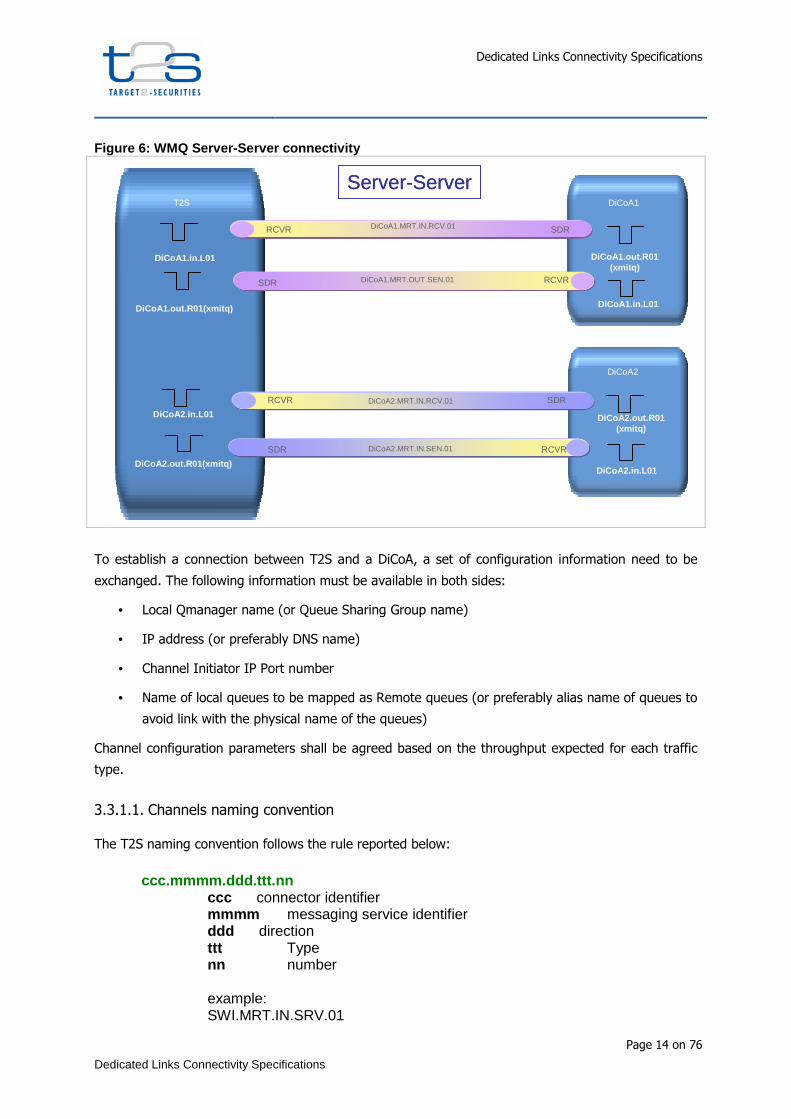
Figure 6: WMQ Server-Server connectivity
T2S
DiCoA1.in.L01
DiCoA1
DiCoA1.out.R01(xmitq)
DiCoA1.in.L01DiCoA1.out.R01(xmitq)
DiCoA2
DiCoA1.MRT.OUT.SEN.01SDR RCVR
DiCoA1.MRT.IN.RCV.01 SDRRCVR
SDRRCVR
SDR RCVRDiCoA2.MRT.IN.SEN.01
DiCoA2.MRT.IN.RCV.01
DiCoA2.in.L01
DiCoA2.out.R01(xmitq)
DiCoA2.out.R01(xmitq)
DiCoA2.in.L01
Server-ServerT2S
DiCoA1.in.L01
DiCoA1
DiCoA1.out.R01(xmitq)
DiCoA1.in.L01DiCoA1.out.R01(xmitq)
DiCoA2
DiCoA1.MRT.OUT.SEN.01SDR RCVR
DiCoA1.MRT.IN.RCV.01 SDRRCVR
SDRRCVR
SDR RCVRDiCoA2.MRT.IN.SEN.01
DiCoA2.MRT.IN.RCV.01
DiCoA2.in.L01
DiCoA2.out.R01(xmitq)
DiCoA2.out.R01(xmitq)
DiCoA2.in.L01
Server-Server
To establish a connection between T2S and a DiCoA, a set of configuration information need to be
exchanged. The following information must be available in both sides:
• Local Qmanager name (or Queue Sharing Group name)
• IP address (or preferably DNS name)
• Channel Initiator IP Port number
• Name of local queues to be mapped as Remote queues (or preferably alias name of queues to
avoid link with the physical name of the queues)
Channel configuration parameters shall be agreed based on the throughput expected for each traffic
type.
3.3.1.1. Channels naming convention
The T2S naming convention follows the rule reported below:
ccc.mmmm.ddd.ttt.nn
ccc connector identifier mmmm messaging service identifier ddd direction ttt Type nn number example: SWI.MRT.IN.SRV.01

Dedicated Links Connectivity Specifications
Page 15 on 76
Dedicated Links Connectivity Specifications
The name of the channel is limited to 20 characters.
In the following table detailed information are reported about the field values and their description.
FIELD VALUES EG. DESCRIPTION
ccc Swi Connector name or application identifier or DiCoA identifier
mmmm MRT Messaging services identifier. Accepted values are
MRT: messages RT
MSF: messages SnF
FRT: Files RT
FSF: Files SnF
MRTK: ACK for messages RT
MSFK: ACK for messages SnF
FRTK: ACK for files RT
FSFK: ACK for files SnF
CMD: command
ddd IN Direction of messages in T2S. values accepted are:
IN
OUT
ttt SRV Channel Type. Accepted values are
SRV server connection
CLI client connection
REC receiver
SEN Sender
nn 01 Sequential number
3.3.1.2. Channel security
The channels used to connect WMQ QSG with VAN providers or DiCoAs establish an SSL connection.
The following parameters control the connections:
SSLCAUTH: it is set to “yes”
SSLCIPH: it is set to the algorithm used for the encryption of the traffic
(TLS_RSA_WITH_AES_128_CBC_SHA).
SSLPEER: it is used to establish the SSL connection, to filter the Distinguished Name (DN) of the
certificate from the peer queue manager or client to the other end of a WMQ channel. The connection
is established only if the DN received from the peer matches with the SSLPEER value.
PUTAUTH: this parameter describes what type of authorization must be provided to put messages on
the queues. It is set to ONLYMCA
MCAUSER: it is the RACF userid granted to access the WMQ message queues.

Dedicated Links Connectivity Specifications
Page 16 on 76
Dedicated Links Connectivity Specifications
Figure 7: WMQ security
DicoA
VAN1
DN=Dicoa
DN=VAN1
WMQ z/OS SSL connection
Mutual authentication
DN=T2S
MQDICOA.TO.MQT2S.01 MQDICOA.TO.MQT2S.01 Channel definition• SSL certificate required . : Yes • SSL peer name : CN=dicoa.net, OU=Servizi di certificazione dei sistemi informatici -Collaudo,O=Banca d'Italia Collaudo,C=it• PUTAUTH:OnlyMCA•MCAUSER:DICOA
MQT2S.TO.MQDICOA.01
receiver
sender
Dicoa.queue.01
Dicoa.queue.02
Van1.queue.01
Van1queue.02
MQVAN1.TO.MQT2S.01
MQT2S.TO.MQVAN1.01
receiver
senderDN=T2S
Userid:VAN1
MQVAN1.TO.MQT2S.01 Channel definition• SSL certificate required . : Yes • SSL peer name : CN=van1.net, OU=Servizi di certificazione dei sistemi informatici -Collaudo,O=Banca d'Italia Collaudo,C=it• PUTAUTH:OnlyMCA•MCAUSER:VAN1
Userid: DICOA
Channel initiator Queue Manager
The management of certificates and the process to acquire them is described in the section ‘’Security Services’’
3.4. Message Queues
The T2S queues are divided in different categories:
• The system related queues: they are the queues needed by WMQ to work properly.
• The T2S application queues: they are the queues used by the T2S modules to
communicate within the T2S core system.
• The T2S VAN communication queues: they are the queues used to exchange incoming
and outgoing message traffic to be handled by the VAN provider. More specifically they are
the queues used to exchange data between the T2S middleware and the VAN gateways.
• The T2S DiCoA communication queues: they are the dedicated queues used to exchange
messages between remote directly connected actors and the T2S middleware.
The T2S queues are identified by a specific naming convention.
The queue names are made up of 3 parts separated by a dot (.);
• The first part identifies the application or the connection (VA-NSP or DL) name.
• The second part identifies the ‘purpose’ of the queue (that is the messaging service or the
type of message it refers to).
• The third part is an identifier of the queue type (from a T2S configuration point of view), for
example shared, local or remote and a sequence number (from 01 to 99).

Dedicated Links Connectivity Specifications
Page 17 on 76
Dedicated Links Connectivity Specifications
The name of the queue is limited to 48 characters
cbbl.ddd.xxxxxxxxxx.ttnn cbb block-module / domain / van name/DiCoA l logical environment (optional) ddd direction xxxxxxxxxx name suggested by application supplier tt queue type nn progressive number (optional) example: swi.in.msg_rt.SHnn
FIELD VALUES EG. DESCRIPTION
Cbb SWI Connector name or application identifier or DiCoA identifier
L N Accepted value
E EAC
U UTEST
G MIG1
M MIG2
F PROD
Ddd IN Direction of messages in T2S. values accepted are:
IN
OUT
xxxxxxxxx MSG_RT Free text. For the interface to the network the following is acceptable
MSG_RT
MSG_RT.ACK
MSG_SNF
MSG_SNF.ACK
FILE_RT
FILE_RT.ACK
FILE_SNF
FILE_SNF.ACK
CMD
Tt SH Queue Type. Accepted values are
SH shared
L local
R remote
Nn 01 Sequential number
Furthermore, specific queue types are supported for each category in order to correctly manage the
system.
Dedicated Links Connectivity Specifications
Page 18 on 76
Dedicated Links Connectivity Specifications
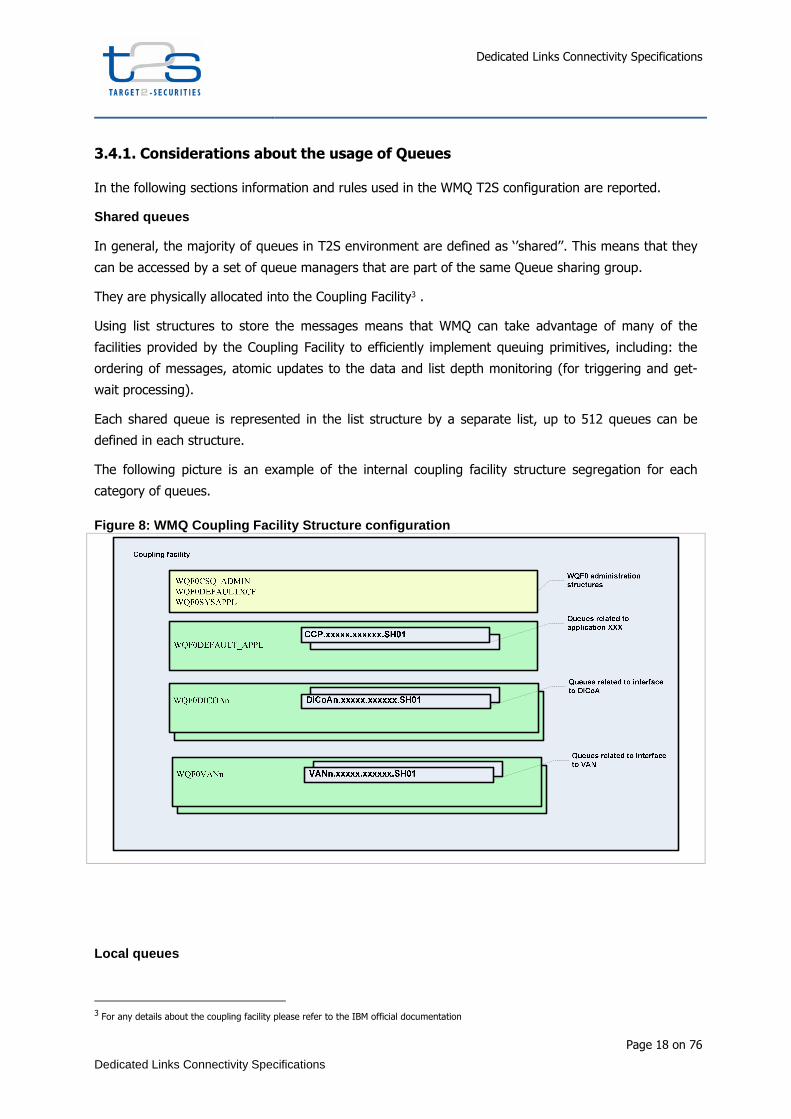
3.4.1. Considerations about the usage of Queues
In the following sections information and rules used in the WMQ T2S configuration are reported.
Shared queues
In general, the majority of queues in T2S environment are defined as ‘’shared’’. This means that they
can be accessed by a set of queue managers that are part of the same Queue sharing group.
They are physically allocated into the Coupling Facility3 .
Using list structures to store the messages means that WMQ can take advantage of many of the
facilities provided by the Coupling Facility to efficiently implement queuing primitives, including: the
ordering of messages, atomic updates to the data and list depth monitoring (for triggering and get-
wait processing).
Each shared queue is represented in the list structure by a separate list, up to 512 queues can be
defined in each structure.
The following picture is an example of the internal coupling facility structure segregation for each
category of queues.
Figure 8: WMQ Coupling Facility Structure configura tion
Local queues
3 For any details about the coupling facility please refer to the IBM official documentation
Dedicated Links Connectivity Specifications
Page 19 on 76
Dedicated Links Connectivity Specifications
Queues defined as local can be accessed only by a specific queue manager. They are physically
located on the same system as the related queue manager.
In T2S this queue category is used only for limited purposes (eg. Backout error queues).
Remote queues
Remote queues are used in order to provide put access to queues that are local to a remote system.
Any message put onto a remote queue is automatically routed to the associated platform and local
queue by the queue manager via the channels mechanism.
Remote queues only allow programs to put messages on (but not to get messages from).
Persistent and Non-persistent Messages
Persistence of messages ensures the availability of the message even in case of WMQ system failure.
All persistent messages are logged and can be recovered from the logs in the event of a CF outage or
structure failure in case of shared queues, and in case of WMQ failure for local queues.
Non-persistent messages are not logged, so they cannot survive to a WMQ server failure. They cannot
be recovered from the log if there is a structure or CF outage (in case of shared queues) or WMQ
failure (in case of local queues).
Due to performance constraints and to the high volume and throughput required by the T2S business,
the persistence of the messages is evaluated case by case (or, more generally, for messaging service
typology). In fact, persistence causes a performance overhead due to the write operation on the WMQ
logs. In case of usage of non persistent messages, the application that writes the messages into the
queue must persist them on a DB before writing them in the MQ queues. This is especially requested
for the implementation of the communication with T2S. An application that sends messages to T2S
and does not want to use the MQ messages persistence, must provide functionalities to be able to re-
send the messages in case of failure (see section ‘’ re-transmission of messages and files in case of
DiCoA (or network) unavailability” ).
Dead letter queue (DLQ)
The T2S installation does not use the Dead letter queue due to the necessity to ensure the order of
messages processing (to the maximum extent possible for a parallel environment). This forces the
applications to manage the errors returned by the queue manager in case of ‘’erroneous’’ addressing
of messages to unavailable queues.
Backout queues
In case of errors in reading a message from a queue, it could be useful to create a backout queue to
avoid that applications start looping in reading the erroneous or wrongly formatted message.

Dedicated Links Connectivity Specifications
Page 20 on 76
Dedicated Links Connectivity Specifications
Every time a message is backed out on the queue, the value of a ‘’backout counter’’ is increased. It is
possible to indicate:
• the name of the backout queue to be used to redirect the wrongly formatted messages.
• The backout threshold to indicate what is the value of message backout attempts after which
the message is routed to the backout queue.
• The retention interval after which the requeued messages in the backout queue can be
automatically dropped by WMQ (after a cleanup process is run).
In T2S the backout queues must be used by the application developer to avoid that wrongly formatted
messages can cause loop in the application. Moreover, backout queues will be defined in all the WMQ
instances as local queues to avoid filling the coupling facilities with orphan messages.
Putting messages and managing connections
Here below some recommendations for the usage of the ‘’T2S incoming queues’’ are listed:
• Avoid the execution or multiple MQPUT calls in a synchpoint without committing them. The
affected queues may fill up with messages that are currently inaccessible by the receiving T2S
middleware.
• Properly close and disconnect the connections prior to disconnection or shut-down of the
putting application. Failure to do so will result in hung connections, which will increase
resource consumption and cause the saturation of available connections.
Queue security is managed by RACF specific profiles, defined to restrict access to the content of the
queue only the allowed users. The naming convention adopted for the queue names facilitate the
profile definition.
Access to the DiCoA dedicated queues is controlled by a specific RACF userid associated via the
mechanism explained in paragraph ‘’Channel Security’’.
In the testing environment, access to the content of the queues is allowed to the WMQ
administrators.
In the production environment, the content of the queues can be accessed by the WMQ
administrators for debugging or recovery purposes only after a specific security request to activate the
auditable RACF Group defined for last level support intervention.

Dedicated Links Connectivity Specifications
Page 21 on 76
Dedicated Links Connectivity Specifications
3.4.1.1. Configuration example in a sender-receiver scenario (from a T2S perspective)
QUEUE NAME T2S SCOPE CONSUMER MESSAGE
DIRECTION QUEUE TYPE
(T2S) TRANSMISSION QUEUE CHANNEL CHANNEL
TYPE
ABC.in.msg_rt.SHnn msg rt incoming request T2S middleware t2s incoming flow shared (local) ABC.MRT.IN.REC.01 receiver
ABC.in .msg_rt.ack.SHnn msg rt incoming ack from GW T2S middleware t2s incoming flow shared (local) ABC.MRTK.IN.REC.01 receiver
ABC.in.file_rt.SHnn file rt incoming request T2S middleware t2s incoming flow shared (local) ABC.FRT.IN.REC.01 receiver
ABC.in.file_rt.ack.SHnn file rt incoming ack from GW T2S middleware t2s incoming flow shared (local) ABC.FRTK.IN.REC.01 receiver
ABC.in.msg_snf.SHnn msg snf incoming request T2S middleware t2s incoming flow shared (local) ABC.MSF.IN.REC.01 receiver
ABC.in.msg_snf.ack.SHnn msg snf incoming ack from GW T2S middleware t2s incoming flow shared (local) ABC.MSFK.IN.REC.01 receiver
ABC.in.file_snf.SHnn file snf incoming request T2S middleware t2s incoming flow shared (local) ABC.FSF.IN.REC.01 receiver
ABC.in.file_snf.ack.SHnn file snf incoming request T2S middleware t2s incoming flow shared (local) ABC.FSFK.IN.REC.01 receiver
ABC.in.cmd.SHnn command response from GW T2S middleware t2s incoming flow shared (local) ABC.CMD.IN.REC.01 receiver
ABC.out.msg_rt.Rnn msg rt outgoing response ABC gateway t2s outgoing flow Remote ABC.out.msg_rt.trn.SHnn ABC.MRT.OUT.SEN.01 sender
ABC.out.msg_rt.ack.Rnn msg rt outgoing ack to GW ABC gateway t2s outgoing flow Remote ABC.out.msg_rt.trn.SHnn ABC.MRTK.OUT.SEN.01 sender
ABC.out.file_rt.Rnn file rt outgoing response ABC gateway t2s outgoing flow Remote ABC.out.file_rt.trn.SHnn ABC.FRT.OUT.SEN.01 sender
ABC.out.file_rt.ack.Rnn file rt outgoing ack to GW ABC gateway t2s outgoing flow Remote ABC.out.file_rt.trn.SHnn ABC.FRTK.OUT.SEN.01 sender
ABC.out.msg_snf.Rnn msg snf outgoing request ABC gateway t2s outgoing flow Remote ABC.out.msg_rt.trn.SHnn ABC.MSF.OUT.SEN.01 sender
ABC.out.msg_snf.ack.Rnn msg snf outgoing ack to GW ABC gateway t2s outgoing flow Remote ABC.out.msg_rt.trn.SHnn ABC.MSFK.OUT.SEN.01 sender
ABC.out.file_snf.Rnn file snf outgoing request ABC gateway t2s outgoing flow Remote ABC.out.file_snf.trn.SHnn ABC.FSF.OUT.SEN.01 sender ABC.out.file_snf.ack.Rnn file snf outgoing ack to GW ABC gateway t2s outgoing flow Remote ABC.out.file_snf.trn.SHnn ABC.FSFK.OUT.SEN.01 sender ABC.out.cmd.Rnn command request to GW ABC gateway t2s outgoing flow Remote ABC.out.cmd.trn.SHnn ABC.CMD.OUT.SEN.01 sender

Dedicated Links Connectivity Specifications
Page 22 on 76
Dedicated Links Connectivity Specifications
3.5. DiCoa-DL specific usage of DEP
The following sections describe the specific usage of DEP protocol by DiCoA using the DL-NSP
connection.
3.5.1. Store-and-Forward messages exchange
It is expected that dep:DeliveryNotification flag, in case of DiCoA-DL, is set to NO to avoid useless
messages to be exchanged between the DEP counterparts.
Moreover the retry mechanism in the DiCoA-DL is implemented at sender level and doesn’t perform
any suspension of store-and-forward messages/files traffic.
3.5.2. Exchange Header validation and tag usage
In case of DiCoA-DL the Exchange Header validation checks that the channel and the related WMQ
queue is consistent with the user specified in the Sender: field of the ExchangeHeader.
T2S middleware checks that the TechnicalServiceId specified in the Exchange Header corresponds to
the incoming queue used by the DiCoA-DL (this includes the selected “logical environment’’ control).
Obviously for a single DEP request/response primitive not all information contained in
ExchangeHeader is significant for data exchange flow.
Next tables include an exhaustive list of the fields required for real-time and store-and-forward
scenario. DEP validation functionality is applied on all the fields of the ExchangeHeader: so, if
information is present that does not pertain to the primitive being handled, the outcome of the
validation will be negative.

Dedicated Links Connectivity Specifications
Page 23 on 76
Dedicated Links Connectivity Specifications
Table 1: DEP ExchangeHeader Fields in T2S outbound Real-Time communication schema
DEP EXCHANGE HEADER
ELEMENTS IN
T2S R-T OUTBOUND SCENARIO
T2S REQUEST DICOA ACK DICOA RESPONSE T2S ACK
dep:Version V4 V V V
dep:Sender V [T2S] V [DiCoA] V [DiCoA] V [T2S]
dep:Receiver V [DiCoA] V [T2S] V [T2S] V [DiCoA]
dep:TechnicalServiceId
V [with msg-pattern MSGRT or FILERT]
V5* V* V*
dep:RequestType V V* V* V*
dep:CommunicationId X6 V V* V*
dep:T2SMessageId V V* V* V*
dep:T2SActorMessageId X X V V*
dep:EntryTimestamp X X X X
dep:SendTimestamp V V* V V*
dep:ReceiveTimestamp X V X V
dep:PDMHistory X X X X
dep:DeliveryMode V [RT] V [RT] V [RT] V [RT]
dep:DeliveryNotification X X X X
dep:NonRepudiationExchange V V* V* V*
dep:Compression V V* V* V*
dep:ExchangeStatus X V V V
dep:ErrorDescription X V [NAN, with ExchangeStatus=KO]
V [Only with ExchangeStatus=KO]
V [NAN, with ExchangeStatus=KO]
dep:MessageDigest X V [if NonRepu-diationExchange is set]
X V [if NonRepu-diationExchange is set]
4 Element is present in this DEP message
5 Element is present in this DEP message with the same value of previous received message
6 Element is not present in this DEP message

Dedicated Links Connectivity Specifications
Page 24 on 76
Dedicated Links Connectivity Specifications
Table 2: DEP ExchangeHeader Fields in T2S inbound R eal-Time communication schema
DEP EXCHANGE HEADER
ELEMENTS IN
T2S R-T INBOUND SCENARIO
DICOA REQUEST
T2S ACK T2S RESPONSE DICOA ACK
dep:Version V V V V
dep:Sender V [DiCoA] V [T2S] V [T2S] V [DiCoA]
dep:Receiver V [T2S] V [DiCoA] V [DiCoA] V [T2S]
dep:TechnicalServiceId
V [with msg-pattern MSGRT or FILERT]
V* V* V*
dep:RequestType V V* V* V*
dep:CommunicationId V V* V* V*
dep:T2SMessageId X X V V*
dep:T2SActorMessageId V V* V* V*
dep:EntryTimestamp X X X X
dep:SendTimestamp V V* V V*
dep:ReceiveTimestamp X V X V
dep:PDMHistory X X X X
dep:DeliveryMode V [RT] V [RT] V [RT] V [RT]
dep:DeliveryNotification X X X X
dep:NonRepudiationExchange V V* V* V*
dep:Compression V V* V* V*
dep:ExchangeStatus X V V V
dep:ErrorDescription X V [NAN, with ExchangeStatus=KO]
V [Only with ExchangeStatus=KO]
V [NAN, with ExchangeStatus=KO]
dep:MessageDigest X V [if NonRepu-diationExchange is set]
X V [if NonRepu-diationExchange is set]

Dedicated Links Connectivity Specifications
Page 25 on 76
Dedicated Links Connectivity Specifications
Table 3: DEP ExchangeHeader Fields in T2S outbound Store-and-Forward communication schema
DEP EXCHANGE HEADER
ELEMENTS IN
T2S SNF OUTBOUND SCENARIO
T2S REQUEST DICOA ACK
dep:Version V V
dep:Sender V [T2S] V [DiCoA]
dep:Receiver V [DiCoA] V [T2S]
dep:TechnicalServiceId V [with msg-pattern MSGSNF or FILESNF]
V*
dep:RequestType V V*
dep:CommunicationId X V
dep:T2SMessageId V V*
dep:T2SActorMessageId X X
dep:EntryTimestamp X X
dep:SendTimestamp V V*
dep:ReceiveTimestamp X V
dep:PDMHistory V [In case of retry] V [In case of retry]
dep:DeliveryMode V [SF] V [SF]
dep:DeliveryNotification V [not meaningful for DiCoA]
V*
dep:NonRepudiationExchange V V*
dep:Compression V V*
dep:ExchangeStatus X V
dep:ErrorDescription X V [NAN, with ExchangeStatus=KO]
dep:MessageDigest X V [if NonRepudiation-Exchange is set]
Dedicated Links Connectivity Specifications
Page 26 on 76
Dedicated Links Connectivity Specifications
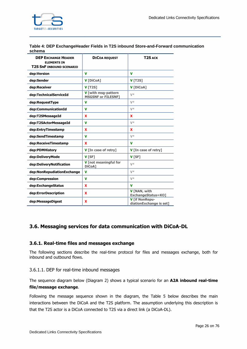
Table 4: DEP ExchangeHeader Fields in T2S inbound S tore-and-Forward communication schema
DEP EXCHANGE HEADER
ELEMENTS IN T2S SNF INBOUND SCENARIO
DICOA REQUEST T2S ACK
dep:Version V V
dep:Sender V [DiCoA] V [T2S]
dep:Receiver V [T2S] V [DiCoA]
dep:TechnicalServiceId V [with msg-pattern MSGSNF or FILESNF]
V*
dep:RequestType V V*
dep:CommunicationId V V*
dep:T2SMessageId X X
dep:T2SActorMessageId V V*
dep:EntryTimestamp X X
dep:SendTimestamp V V*
dep:ReceiveTimestamp X V
dep:PDMHistory V [In case of retry] V [In case of retry]
dep:DeliveryMode V [SF] V [SF]
dep:DeliveryNotification V [not meaningful for DiCoA]
V*
dep:NonRepudiationExchange V V*
dep:Compression V V*
dep:ExchangeStatus X V
dep:ErrorDescription X V [NAN, with ExchangeStatus=KO]
dep:MessageDigest X V [if NonRepu-diationExchange is set]
3.6. Messaging services for data communication with DiCoA-DL
3.6.1. Real-time files and messages exchange
The following sections describe the real-time protocol for files and messages exchange, both for inbound and outbound flows.
3.6.1.1. DEP for real-time inbound messages
The sequence diagram below (Diagram 2) shows a typical scenario for an A2A inbound real-time
file/message exchange.
Following the message sequence shown in the diagram, the Table 5 below describes the main
interactions between the DiCoA and the T2S platform. The assumption underlying this description is
that the T2S actor is a DiCoA connected to T2S via a direct link (a DiCoA-DL).

Dedicated Links Connectivity Specifications
Page 27 on 76
Dedicated Links Connectivity Specifications
Diagram 2: Real-Time T2S inbound message – SD of th e main Use Case
Table 5: Real-Time T2S inbound message – Descriptio n of the main Use Case
STEP
NUMBER STEP DESCRIPTION
1) The DiCoA-DL sends a real-time message/file to the T2S platform by a "Request" primitive.
The "Delivery Mode" field is set to "RT". The field T2SActorMessageId has to be set by DiCoA to the unique message identification generated at Directly Connected T2S Actor gateway site, the field CommunicationId has to be set by DicoA to the unique message identification at communication level.
2) The T2S Platform receives the message/file and performs the validation check of the "Exchange Header"; if the compression flag is set, the T2S middleware invokes the DEP decompression function. Finally, the T2S Middleware checks the size of the uncompressed message/file.
3) After the validation of the envelope, the T2S Middleware sends back to the DL-DiCoA a PAN or NAN "Technical Ack" setting the “dep:ReceiveTimestamp” with the receiving time.
If a NAN is returned the flow is completed and the reason of the failure is set in the field dep:ErrorCode and dep:ErrorDescription of the response message’s header (ref. alternative scenario modeled in Diagram 3).
4) The message/file is passed to the T2S Application.

Dedicated Links Connectivity Specifications
Page 28 on 76
Dedicated Links Connectivity Specifications
5) T2S Application sends a response message to the T2S Middleware.
As an alternative case, if the response is handed over after the timeout, the T2S middleware has to manage this scenario as described in section 5.2.3 – Timeout Management
6) The T2S Middleware sends the "response" message to the DL-DiCoA, setting in the "Exchange Header" the "dep:T2SMessageID" to a unique identifier and keeping all other fields as received in the “request” message. If the flag is set, the T2S Middleware invokes the DEP compression function.
As an alternative case, if the response is oversized (over 32kB for message and over 32MB for file), the T2S middleware has to manage this scenario as described in section 5.2.4 - Oversize Management
7) The DiCoA-DL receives the "response" and performs the validation check of the "Exchange Header" and of the size.
8) If the response is ok, DiCoA-DL sends a PAN Technical Ack.
If the validation process fails, or the size of the response is not in the allowed range, then DiCoA-DL sends back to the T2S Platform a "NAN Technical Ack" setting in the appropriate way the "dep:ExchangeStatus" and "dep:ErrorDescription" fields.
Diagram 3: Real-Time T2S inbound message – Alternat ive SD – NAN technical ack
3.6.1.2. DEP for real-time outbound messages
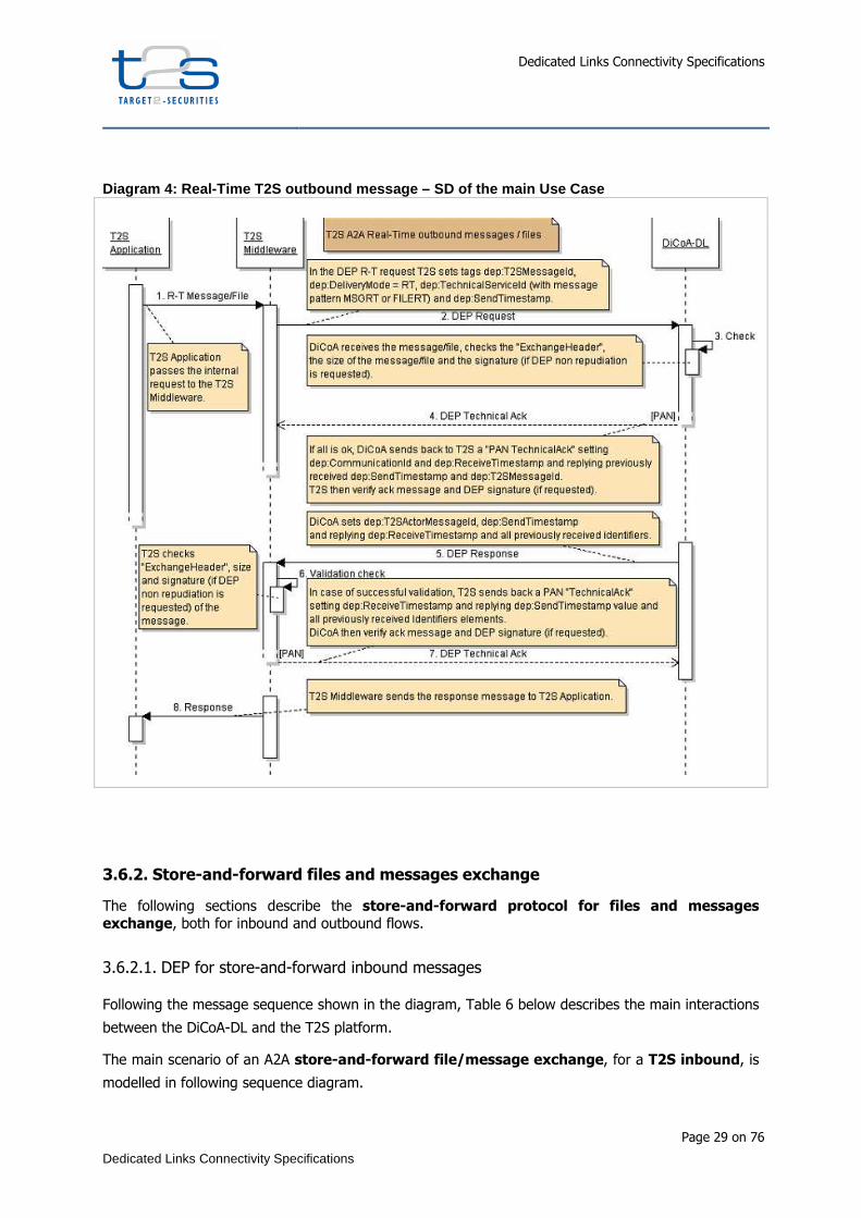
The sequence diagram below (Diagram 4) shows a typical scenario for an A2A outbound real-time
file/message exchange.
Currently there are no business cases for the usage of this service by T2S.
Dedicated Links Connectivity Specifications
Page 29 on 76
Dedicated Links Connectivity Specifications
Diagram 4: Real-Time T2S outbound message – SD of t he main Use Case
3.6.2. Store-and-forward files and messages exchange
The following sections describe the store-and-forward protocol for files and messages
exchange, both for inbound and outbound flows.
3.6.2.1. DEP for store-and-forward inbound messages
Following the message sequence shown in the diagram, Table 6 below describes the main interactions
between the DiCoA-DL and the T2S platform.
The main scenario of an A2A store-and-forward file/message exchange, for a T2S inbound, is
modelled in following sequence diagram.
Dedicated Links Connectivity Specifications
Page 30 on 76
Dedicated Links Connectivity Specifications
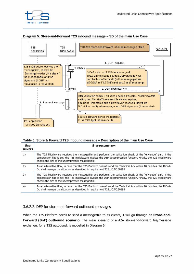
Diagram 5: Store-and-Forward T2S inbound message – SD of the main Use Case
Table 6: Store & Forward T2S inbound message – Desc ription of the main Use Case
STEP
NUMBER STEP DESCRIPTION
1) The T2S Middleware receives the message/file and performs the validation check of the "envelope" part. if the compression flag is set, the T2S middleware invokes the DEP decompression function. Finally, the T2S Middleware checks the size of the uncompressed message/file.
2) As an alternative flow, in case that the T2S Platform doesn’t send the Technical Ack within 10 minutes, the DiCoA-DL shall manage the situation as described in requirement T2S.UC.TC.30195
3) The T2S Middleware receives the message/file and performs the validation check of the "envelope" part. if the compression flag is set, the T2S middleware invokes the DEP decompression function. Finally, the T2S Middleware checks the size of the uncompressed message/file.
4) As an alternative flow, in case that the T2S Platform doesn’t send the Technical Ack within 10 minutes, the DiCoA-DL shall manage the situation as described in requirement T2S.UC.TC.30195
3.6.2.2. DEP for store-and-forward outbound messages
When the T2S Platform needs to send a message/file to its clients, it will go through an Store-and-
Forward (SnF) outbound scenario. The main scenario of a A2A store-and-forward file/message
exchange, for a T2S outbound, is modelled in Diagram 6.

Dedicated Links Connectivity Specifications
Page 31 on 76
Dedicated Links Connectivity Specifications
Diagram 6: Store-and-Forward T2S outbound message – SD of the main Use Case
Following the message order showed by diagram, Table 7 describes the main interactions between
T2S Platform and DiCoA-DL.
Table 7: Store & Forward T2S outbound message – Des cription of the main Use Case
STEP
NUMBER STEP DESCRIPTION
1) The T2S Application passes the request to the T2S Middleware
2) The T2S Middleware sends a "Request" message/file primitive to the DiCoA-DL. The "T2S Message Id" envelope field is generated by the T2S Platform (this identifier shall be unique at T2S level). The "Delivery Mode" field is set to "SF".
3) The DiCoA-DL receives the message/file and performs the validation check of the "Envelope" part and the validation of the size of the message/file.
4) If the validation check is passed, DiCoA-DL sends back to the T2S Platform a "PAN Technical Ack" setting “dep:CommunicationId” , “dep:ReceiveTimestamp” and “dep:T2SMessageId” with values generated for the incoming message with the receiving time.
If the validation process fails, the DiCoA-DL sends back to the T2S Platform a "NAN Technical Ack" setting in the "dep:ExchangeStatus" and "dep:ErrorDescription" fields appropriately; the flow is so completed.

Dedicated Links Connectivity Specifications
Page 32 on 76
Dedicated Links Connectivity Specifications
4. USER TO APPLICATION (U2A)
Using this communication mode, the Directly Connected T2S Actor can perform both query and
update operations. Users can also see status reports of incidents and problems and access the Long
Term Statistical Information system.
Access to T2S applications in U2A makes always use of a HTTPS connections as shown in the figure
below.
DiCoA T2S Platform
U2A
DL-NSP
DNS
DNS
HTTP ForwardProxy (optional)
DNS
https
Smartcardauthentication
+Access control
MIG2 logical environment
MIG1 logical environment
Application Server
EAC logical environment.
Application Server
PROD logical environment
Name resolution
Region 1
Region 2
DL-NSP
VP
N B
ox +
R
oute
r
VP
N B
ox +
R
oute
rV
PN
Box
+
Rou
ter
The main components that are involved in the interaction are:
• the user workstation where the users interacts with a browser
• if present, a forward proxy in the DiCoA domestic network; anyway, a firewalling device in the DiCoA domestic network for filtering the traffic from authorized workstations.
• the DNS in the domestic network that is dedicated to Internet name resolution; the counterpart DNS in T2S network that resolves the T2S names with IP addresses.
• the DL-NSP network that interconnects the DiCoA systems to T2S Platform
• The T2S systems that are dedicated to authenticate the user with the certificate that is provided by the user and to authorize the access to the application
• The web application servers where the T2S applications run.

Dedicated Links Connectivity Specifications
Page 33 on 76
Dedicated Links Connectivity Specifications
Different logical environments of the T2S applications can be accessed by the user at different URLs.
All U2A interactions are based on HTTPs protocol to assure confidentiality and integrity of the
exchanged data. HTTPs traffic between the users' workstations and the T2S Platform must be enabled
on the network devices at the DiCoA site, at the DL-NSP level and at T2S entry firewall.
End users at the Direct Connected T2S Actor who need to use U2A functionality shall be assigned a
certificate; certificates and related private keys are stored in a smart-card or in a USB token..
The DiCoA shall check the authorization of the end users’ workstations to access the T2S Platform
based on the Network level. The IP of the end user access point is checked by the DiCoA firewall to
authorize the access to the requested T2S URLs when the end user browser tries to establish a HTTPS
session with the T2S Platform.
This paragraph describes the flow performed in the U2A interactions.
At DiCoA site:
• The user opens a browser on a workstation that is connected to the DiCoA local network and
enters the URL of one the T2S U2A applications.
• In case the user’s browser is configured to use a proxy in the DiCoA network, the URL request
is forwarded to the proxy.
• The user’s workstation or the domestic proxy requests the domestic DNS to resolve the
hostname in the URL; to perform this task the domestic DNS forward the name resolution
request to the T2S DNS.
• The DiCoA network devices (e.g. the firewall or the proxy) performs a check whether the
workstation of the end user is authorised to access the requested IP.
• If the check is successful, the end user is able to establish an HTTPs session with the T2S
system at the IP address that is resolved by the DNS.
• If not authenticated, the user will be prompted to specify a valid certificate used for the
authentication of the end user;
• If foreseen by the T2S application, an applet can be downloaded on the end user's
workstation to sign the XML message for the purpose of non-repudiation; the end user sends
signed data via a HTTPs session to the T2S web application server.
At the T2S Site:
• The web application server receives the request to establish a HPPTS request
• If not authenticated it redirects the user browser on a page where the certificate based
authentication occurs;
• The T2S Platform validates the certificate by connecting to the T2S PKI for certificate
validation (CRL, CSL).

Dedicated Links Connectivity Specifications
Page 34 on 76
Dedicated Links Connectivity Specifications
• After authentication an identification phase can be necessary when the same certificate is
associated to more than one “system user” in T2S platform; in this case the user has to select
which “system user” he wants to access like in that specific U2A session.
• If the user has been authenticated, the HTTPS request is forwarded to the proper T2S web
application server.
• If during the interaction an XML signed message is uploaded on the T2S web server,
signature validation will be completed by the T2S Platform based on the certificate used for
digital signature;
• The web Application sends a (business) acknowledgement via HTTPs session.
The usage of T2S DNS to resolve the hostname in the URL allows the user’s browser to transparently
access the T2S application server in the proper region where the requested logical environment is
hosted.
Dedicated Links Connectivity Specifications
Page 35 on 76
Dedicated Links Connectivity Specifications
5. Value Added Connectivity Services
5.1. Security services
Security is of paramount importance for T2S, as very sensitive information will be exchanged between
the T2S Platform and its users.
T2S will provide a PKI infrastructure to generate:
- certificates associated to digital keys used to secure the direct link channel between the WMQ
systems (SSL at T2S side);
- certificates associated to digital keys used for the signature of DEP ExchangeHeader and
inside the Technical Acknowledgement when the non-repudiation have to be used at the DEP
level;
- certificates used for the signature of business Information that are transported by the DEP
protocol;
- certificates for users’ authentication in U2A interaction.
For that purposes purpose it will identify a registration authority (RA) to be involved during the
process of issuing and managing the life cycle of electronic certificates.
This infrastructure will be based on T2S PKI, which consists of:
- a Users Certification Authority, for issuing digital certificates to individual user (named “T2S
CA for Users” in this document);
- an Application Certification authority, for issuing digital certificates to devices, applications
(e.g. SSL certificates) or institutions (“T2S CA for Applications” in this document);
- a Registration Authority, for certificate life cycle management;
The “T2S CA for Users” has been assessed by the ESCB PKI Assessment Body and formally included in
the relevant ESCB-trusted white lists. Digital certificates are issued on cryptographic devices like smart
cards or USB tokens.
The “T2S CA for Applications” has been “cross-certified” by the Entrust 2048 CA with a chaining
agreement, making it trusted by the most popular web browsers. Digital certificates can be issued on
cryptographic hardware (such as HSMs) or software envelopes (PKCS#12). For T2s, the usage of FIPS
140-3 or CC EAL 4+ compliant HSMs is mandatory.

Dedicated Links Connectivity Specifications
Page 36 on 76
Dedicated Links Connectivity Specifications
5.1.1. Certificate revocation list server availability
Both Users and Application Certification Authorities make CRLs available over Internet via HTTP and
LDAP protocol.
The “T2S CA for Users”, additionally, provides an OCSP service. All of these services are accessible
from the Internet. The following table summarizes the CRL Distribution Points for both CAs and the
OCSP service URL.
Table 8: Summary of CRL Distribution Points (e.g. Banca d’Italia PKI)
CA HTTP CRL DISTRIBUTION POINT LDAP CRL DISTRIBUTION
POINT OCSP
Use
rs
www.firmadigitale.bancaditalia.it/crl/crl.crl
ldap.firmadigitale.bancaditalia.it/
cn=Banca%20d'Italia,
ou=Servizi%20di%20certificazione,
o=Banca%20d'Italia/00950501007,
c=IT?certificateRevocationList
ocsp.firmadigitale.bancaditalia.it/ocsp
Ap
pli
ca
tio
n
www.certificazione.bancaditalia.it/crl/crlapp.crl
ldap.certificazione.bancaditalia.it/
ou=Servizi%20di%20certificazione
%20dei%20sistemi%20informatici,
o=Banca%20d'Italia,
c=it?certificateRevocationList
N/A
T2S will provide also a CRL proxy that allows the DiCoA system to access the CRL over the Dedicated
Link network service provider.
5.1.2. Provisioning and management of digital certificates
The following schemes represent the logical flow of certificate issuance to individual users and
applications.
The identification of users by the T2S PKI Registration Authority will be delegated to the T2S Service
Desk that can delegate some tasks to the National Central Bank of the DiCoA’s respective Country.
Regarding certificates for individual users, private and public keys are generated at the PKI site during
the process of producing the smartcard and the certificate.
Regarding application certificates, private and public keys (“key pairs”) are generated on the HSM
device at the DiCoA site; the “T2S CA for Applications” will be responsible of generating the related
certificate based on the Certificate Signing Request (PKCS#10 format) issued by the DiCoA.
The DiCoA shall identify a Security Officer that will be responsible to initiate the certificate request
process and to receive information from the PKI Administrators.
Dedicated Links Connectivity Specifications
Page 37 on 76
Dedicated Links Connectivity Specifications
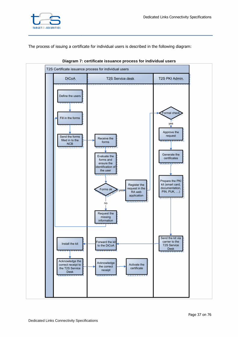
The process of issuing a certificate for individual users is described in the following diagram:
Diagram 7: certificate issuance process for individ ual users
T2S Certificate issuance process for individual users
T2S Service desk T2S PKI Admin.DiCoA
Define the users
Fill in the forms
Send the forms
filled in to the
NCB
Receive the
forms
Evaluate the
forms and
ensure the
identification of
the user
Forms ok
Generate the
certificates
Approve the
request
Register the
request in the
RA web
application
Prepare the PKI
kit (smart card,
documentation,
PIN, PUK, …)
Formal check
Send the kit via
carrier to the
T2S Service
Desk
Forward the kit
to the DiCoAInstall the kit
Acknowledge the
correct receipt to
the T2S Service
Desk
Acknowledge
the correct
receipt
Activate the
certificate
yes
no
Request the
missing
information
yes

Dedicated Links Connectivity Specifications
Page 38 on 76
Dedicated Links Connectivity Specifications
The process of issuing a certificate for individual users envisages that
1. the user is identified by the T2S Service Desk (vis-à-vis identification in the premise of the
NCB of the related Country) before accepting the request to generate the Certificate;
2. the digital keys are generated as part of the process to produce the smartcard/USB token, at
the T2S PKI premises. The certificate is originally “suspended” (the serial number is inserted
into the T2S PKI CRL) ;
3. The individual has to pick up the smartcard/USB token at the premises of the NCB of the
related Country;
4. The certificate is activated (i.e. its serial number is removed from the CRL) after the user has
acknowledged the reception of the smart card/USB token.
Dedicated Links Connectivity Specifications
Page 39 on 76
Dedicated Links Connectivity Specifications
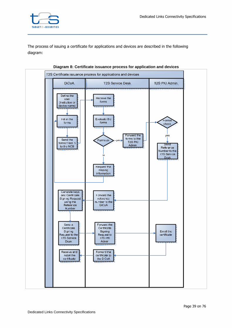
The process of issuing a certificate for applications and devices are described in the following
diagram:
Diagram 8: Certificate issuance process for applica tion and devices

Dedicated Links Connectivity Specifications
Page 40 on 76
Dedicated Links Connectivity Specifications
The process of issuing a certificate for digital keys that must be generated on a device (such as HSM)
at the DiCoA premise envisages that
1. the DiCoA initiates a formal request by describing the usage of the certificate and the
identification of the system or application that will use the certificate (including the DN to be
inserted in the certificate)
2. T2S PKI Administrator sends back a reference number to be used during the process of
generating the digital keys and the Certificate Signing Request file.
3. The DiCoA Security Officer sends the Certificate Signing Request to T2S PKI
4. T2S PKI Administrator sends the generated public certificate to DiCoA Security Officer
5.1.3. Digital signature management
The signature of the business content shall be in XAdES format; it can be generated by using either
the digital keys for the signature that have been provided by the “T2S CA for Users” on cryptographic
devices like smart cards or USB tokens or by Digital keys generated by the DiCoA on his own
hardware Security module. In this case the HSM shall be compliant with FIPS 150 or EAL4+
specifications; certificates associated with such digital keys are issued by the “T2S CA for
Applications”.
The signature of DEP protocol messages will be made using digital certificates provided by the
Applications Users Certificate on HSMs.
5.1.4. Non-repudiation of the exchanged data
In A2A, the non-repudiation of emission and receipt of exchanged data is ruled by the dep:Non-
Repudiation flag in the technical header and it is implemented according to the following assumptions:
For incoming messages, when the dep:nonRepudiation flag is set, the technical envelope shall contain
a digital signature. The digital signature proves that the message has been delivered by the DiCoA.
T2S replies with a technical acknowledgement that contains a digital signature of its content; such a
technical acknowledgement proves that the message was received by T2S.
For outgoing messages, if T2S sets the dep:nonRepudiation flag in the DEP technical header, the
technical envelope contains a digital signature. Such a technical header proves that T2S delivered the
message; the DiCoA shall reply with a technical acknowledgement that contains a digital signature of
its content that proves to T2S that the message was received by the DiCoA systems.
According to W3C’s XML Advanced Electronic Signature recommendations7, the XAdES format satisfies
the legal requirements for advanced electronic signatures as defined in the European Directive on 7 XML Advanced Electronic Signatures (XAdES), W3C Note 20 February 2003, available at http://www.w3.org/TR/XAdES/.
Dedicated Links Connectivity Specifications
Page 41 on 76
Dedicated Links Connectivity Specifications
electronic signatures. It provides basic authentication and integrity protection and can be created
without accessing on-line (time-stamping) services.
When the signature is validated the status of the certificate at the arrival time shall be considered; no
time stamp attribute attached to the signature (as in XAdES-T format) is used.
5.2. Handling of Messaging services
5.2.1. Real-time mode
The real time service is aimed at respecting the response time requirements.
Each request sent via real time service shall receive a response within 60 seconds.
In the case that no response is received within the 60 seconds, a timeout condition shall be raised to
close the real-time session.
On the T2S side, if the request is correctly received and the response is going to be processed, the
timeout condition is handled by a specific process named ‘’timeout management’’ described in depth
in the section “5.3.2 Timeout management”.
The process waiting for the response to a request needs to listen to the specific WMQ queues agreed
during configuration phase. If the response size is over the limit of the selected channel, a specific
process named ‘’oversize management’’ will handle the communication as described in the section
‘’5.2.4 Oversize management’’.
Currently there is no business case scenario that foresees a query sent by T2S to the DiCoA via this
messaging service, so the DiCoA should not implement oversize and timeout management on the
client side, but it should be able to correctly process the incoming messages provided by T2S related
to the above mentioned specific processes.
5.2.2. Store-and-forward mode
The Dedicated Link connectivity is implemented between 2 actors (the DiCoA and T2S). In this
scenario there is no additional actor that can store the messages to ensure delivery to the final
receiver.
For this reason, the store-and-forward service is implemented in a DiCoA configuration inheriting the
WMQ functionalities provided by server-server configuration.
Because automatically managed by the WMQ, the usage of this functionality provides the following
advantages:
• one and only one delivery of messages to the remote WMQ server

Dedicated Links Connectivity Specifications
Page 42 on 76
Dedicated Links Connectivity Specifications
• automatic message resend in case of connection problems, provided by the WMQ
channel agent;
• the usage of transmission queues ensures that messages are stored locally before
being sent to the remote WMQ, and are removed from the local queue only when the
messages persist on the remote queue. Reconnection in case of failure of the channel
is managed automatically by the WMQ channel agents that manages the
synchronization process to check the status of the exchanged and committed
messages;
• the channel (connection) availability means that the messaging service can be used
without having to handle the DEP protocol commands to enable or disable the Store-
and-forward traffic. The “EnableSnfTraffic” – “DisableSnfTraffic’’ DEP primitives have
no sense in this configuration. To enable the SNF traffic, the relative MQ channel will
be started and to disable the SNF traffic, it will be stopped.
Moreover as a possible exception respect to the DEP protocol description the usage of
dep:DeliveryNotifiication flag can be avoided and substituted by verifying the reception of a Technical
ACK generated by T2S to be sure that the message is correctly received by T2S. However a message
with the dep:DeliveryNotification flag set in the ExchangeHeader will not be refused by T2S and will
be treated following the DEP protocol;
In any case, the DiCoA client shall provide a retry mechanism based on the DEP Store and Forward
protocol description that is:
- If a NAN is returned by T2S for a message or File sent via Snf service, the DiCoA shall retry sending the message up to 10 times every 10 minutes.
- If for 10 times the DiCoA receives NAN from T2S this means there is a persistent problem on the platform, so the message shall be marked as ‘’undelivered’’ in the DiCoA site.
- A ‘’resending’’ functionality shall be available at the DiCoA site to recover messages following the rules reported in the section ‘’5.2.5 re-transmission of messages ‘’
5.2.3. Timeout management
For real-time messages exchange, the DEP protocol imposes to handle the entire exchange within a
specified limited time8. As soon as the timeout is expired the communication is interrupted and a
‘’timeout’’ error is generated.
For the query/response message flow, this limitation can interrupt the communication even if the
response is being producing, causing error message generation in a scenario that in reality is working
properly.
To overcome this limit for the production of the response that takes longer that the timeout limitation,
T2S applies an effective protocol.
8 Timeout value can be subjected to change in the future. It is currently fixed to 60 seconds and includes the transport time.

Dedicated Links Connectivity Specifications
Page 43 on 76
Dedicated Links Connectivity Specifications
It defines a timeout limit which anticipates that of the protocol. If the processing takes longer than
the T2S timeout limit the transfer mode of the response changes from real-time to store and forward.
The store and forward mode delivers all requested data properly.
The T2S timeout limit is considerably lower than that of the protocol one, to take in consideration the
transport time.
The following sequence illustrates the timeout management protocol with an example of
query/response flow:
1. the communication counterpart sends a query request in real-time mode to T2S. T2S
starts a timer at query request reception time;
2. T2S processes the query request but the processing time exceeds the T2S timeout limit.
3. If T2S cannot respond to the query request within the timeout limit, the middleware sends
an “Inbound Processing Rejection” admi.007.001.01 ReceiptAcknowledgement is sent as
query response to the communication coutnerpart (sender) indicating that a T2S timeout
has occurred but the request is being processed9.
4. T2S continues to prepare the response. When the data is available, it is sent in store and
forward mode to the communication counterpart according to the routing rule. Oversized
responses are sent according to the default routing rule for the file channel (see below).
The DEP timeout value is fixed to 60 seconds.
The T2S timeout value is configurable. It is initially set to 40 seconds.
Timeout management will be implemented following the schema below.
9 Text of the message will be ICAA001-T2S cannot respond to the query request within the timeout limit. File store and forward network service will be used.

Dedicated Links Connectivity Specifications
Page 44 on 76
Dedicated Links Connectivity Specifications
Diagram 9: Real-Time T2S inbound message – Alternat ive SD – Timeout management
5.2.4. Oversize Data management
DEP protocol is built to allow segregation of traffic and optimization of data exchange based on the
size of the communications.
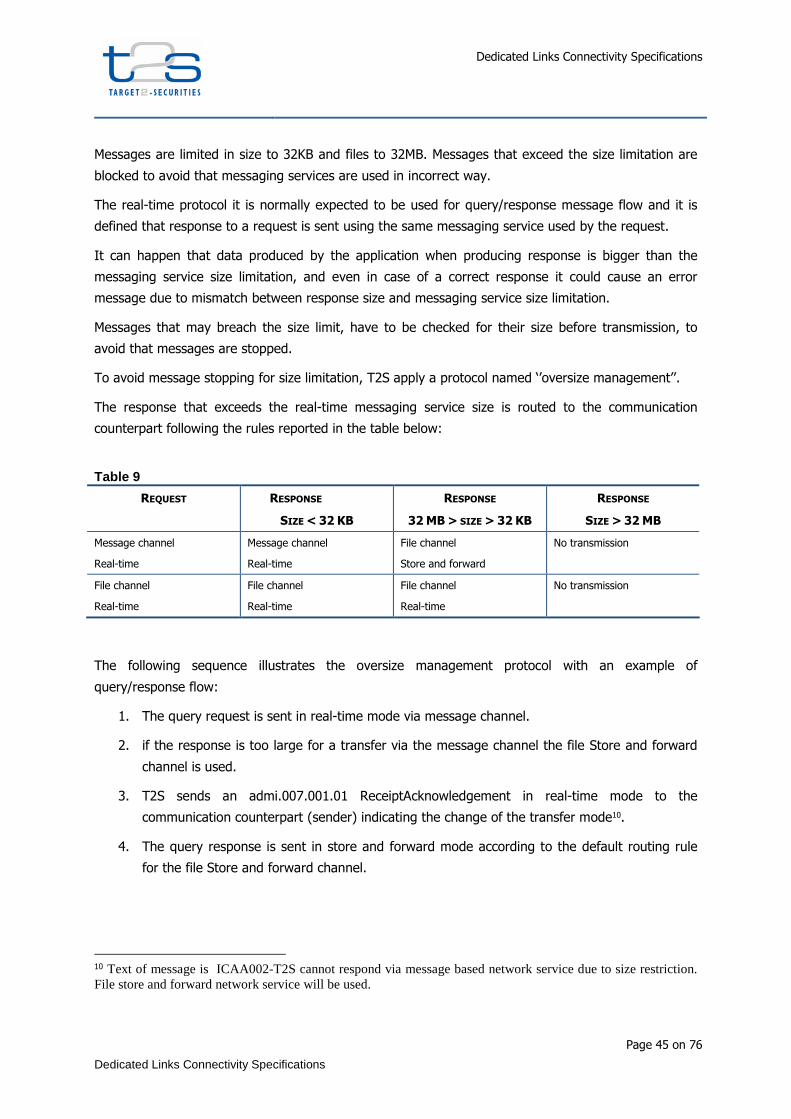
Dedicated Links Connectivity Specifications
Page 45 on 76
Dedicated Links Connectivity Specifications
Messages are limited in size to 32KB and files to 32MB. Messages that exceed the size limitation are
blocked to avoid that messaging services are used in incorrect way.
The real-time protocol it is normally expected to be used for query/response message flow and it is
defined that response to a request is sent using the same messaging service used by the request.
It can happen that data produced by the application when producing response is bigger than the
messaging service size limitation, and even in case of a correct response it could cause an error
message due to mismatch between response size and messaging service size limitation.
Messages that may breach the size limit, have to be checked for their size before transmission, to
avoid that messages are stopped.
To avoid message stopping for size limitation, T2S apply a protocol named ‘’oversize management’’.
The response that exceeds the real-time messaging service size is routed to the communication
counterpart following the rules reported in the table below:
Table 9
REQUEST RESPONSE
SIZE < 32 KB
RESPONSE
32 MB > SIZE > 32 KB
RESPONSE
SIZE > 32 MB
Message channel
Real-time
Message channel
Real-time
File channel
Store and forward
No transmission
File channel
Real-time
File channel
Real-time
File channel
Real-time
No transmission
The following sequence illustrates the oversize management protocol with an example of
query/response flow:
1. The query request is sent in real-time mode via message channel.
2. if the response is too large for a transfer via the message channel the file Store and forward
channel is used.
3. T2S sends an admi.007.001.01 ReceiptAcknowledgement in real-time mode to the
communication counterpart (sender) indicating the change of the transfer mode10.
4. The query response is sent in store and forward mode according to the default routing rule
for the file Store and forward channel.
10 Text of message is ICAA002-T2S cannot respond via message based network service due to size restriction. File store and forward network service will be used.

Dedicated Links Connectivity Specifications
Page 46 on 76
Dedicated Links Connectivity Specifications
5. If the response is bigger than the File channel size limitation, the file is not sent and an
admi.007.001.01 ReceiptAcknowledgement is sent via store and forward channel to the
communication counterpart to alert that response is aborted due to size limitation11.
Regarding the Store and Forward Communication (Reports, Notifications) the channel for the
transmission of push messages have to be configured by the receiver via dedicated routing rules.
These have to follow the technical restrictions for the various channels, i. e. it is not possible to
configure a rule for the message channel for messages larger than 32 kB, while a routing rule for the
file channel for messages with a lower size than 32 kB would be valid.
If no routing rule is configured for a present communication, the default routing rules are applied.
According to such default rules routing occurs via the message channel for all messages up to 32 kB
and via the file channel for all larger messages.
If no default routing rules are present, the message is not routed to the network and an alarm is
raised to the technical monitor to alert the operators to check the problem or alert the receiver to
update the routing rules in the Static Data.
The oversize management will be implemented following the schemas below.
In the first scenario (Real Time message/file channel with response size < 32 KB), the size of the
response is correct with the same channel that was used for the query request. So, T2S middleware
sends the response message over the same channel, as modeled in previous Diagram 2: Real-Time
T2S inbound message – SD of the main Use Case.
For file channel, this scenario applies with 32 MB > response size > 0 KB too.
11 Text of message is ICAA003-T2S cannot respond to the query due to 32MB size restriction

Dedicated Links Connectivity Specifications
Page 47 on 76
Dedicated Links Connectivity Specifications
The second scenario is when the request is sent via the message channel and the size of the response
is too large for a transfer via the message channel. In this case, T2S middleware sends the response
in store-and-forward mode, using file channel.
Diagram 10: Real-Time T2S inbound message – Alterna tive SD – Oversize - channel transaction
The third and final scenario is when response size > 32 MB; in this case, the size of the response is
too large for a transfer via the file channel and so the transmission is aborted.

Dedicated Links Connectivity Specifications
Page 48 on 76
Dedicated Links Connectivity Specifications
Diagram 11: Real-Time T2S inbound message – Alterna tive SD – Oversize - no transmission
5.2.5. Re-transmission of messages and files in case of DiCoA (or network)
unavailability.
In case of technical error (e.g service interruption due to failure of an infrastructural element),
resending of messages takes place to be sure that nothing has being lost.
Resendig functionalities shall be provided by the DiCoA.
The Resending functionality is implemented in T2S. To be able to send again a single message or a
group of messages the messages can be selected following the listed criteria:
• Sender
• Receiver
• Service used
• Message Identifier
• Time interval (date and time)
• Message type

Dedicated Links Connectivity Specifications
Page 49 on 76
Dedicated Links Connectivity Specifications
• Direction (sent or received)
The messages are then re-sent out without the ‘’duplication flag’’. Checks for duplication function are
needed on the DiCoA’s side in this case.
The DiCoAs are requested to implement similar functionalities to recover from any disaster recovery
scenario.
Dedicated Links Connectivity Specifications
Page 50 on 76
Dedicated Links Connectivity Specifications
6. Operational Management
6.1. Registration Process
6.2. Recovery Management
There is a basic recovery principle which applies to the Dedicated Link solution: on one side T2S must
be able to recover the U2A (https) and A2A (WMQ/DEP) services, at any of the four available sites,
with no changes from the DiCoA; on the other side the DiCoA must be able to recover the A2A (WMQ)
service, at any available site, with no changes from T2S. The goal is to have a data center agnostic
service: DiCoAs do not perceive which is the T2S active region, DiCoAs do not discern the swap of
active Region (the so called rotation), all this is fully transparent to the DiCoAs, thus no configuration
changes in the DiCoA systems are envisaged. To achieve this a DNS based solution is in place.
Each T2S data center is reachable via a specific IP subnets (DC1 is reachable via IP subnet1, DC2 is
reachable via IP subnet2, DC3 is reachable via IP subnet3, DC4 is reachable via IP subnet4). Between
the two T2S sites in the same region there is a layer 2 (L2) VLAN extension. Each data center runs
IBM WebSphere WMQ and DNS services. These local DNS caching services are updated and are
forwarders of a more internal DNS which “knows” on which T2S data center a certain service is
running.
Example: DiCoA looking for T2S services
The DNS name servers implemented at all four T2S sites (DC1, DC2, DC3, DC4) are authoritative for the
T2S domain (for example t2s.int). These name servers (for example ns[1-4].t2s.int) are updated by T2S
root DNS servers located anywhere in the T2S core, and are queried by the DNS client located at any
of the DiCoA sites (DC5, DC6).
Under normal operations a T2S service manager willing to run a specific T2S service (for example
xyz.t2s.int) on a specific T2S data center (for example the IBM WebSphere WMQ running on DC3), via
the operation support team, updates the root DNS, which then updates the DNS caching name
servers, thus the respective DNS records - describing where the service is active - are ready for
queries.
The DiCoAs (either A2A or U2A) want to connect to the xyz.t2s.int service, the DiCoA’s DNS client
points to all of the T2S name servers (authoritative for the t2s.int name resolution) and starts round
robin queries for example from DC5 to any of the four T2S DNS name servers. The name server at DC1

Dedicated Links Connectivity Specifications
Page 51 on 76
Dedicated Links Connectivity Specifications
(ns1.t2s.int) replies that the host xyz.t2s.int is active at a specific DC3 IP address and then the DiCoA
can establish a TCP session to the WMQ service available at DC312.
The following picture describes the solution:
Under recovery operations the T2S service manager might decide for whatever reason to run the
specific T2S service on another T2S data center (for example DC4), again via the operation support
team the root DNS is updated with the most current information, it then updates the DNS caching
name servers, which are again ready for queries. The DiCoA still wants to connect to the xyz.t2s.int
service, starts the round robin queries, for example from DC5, the name server at DC2 (ns2.t2s.int)
replies that the host xyz.t2s.int is active at a specific DC4 IP address and the DiCoA establishes a new
TCP session to the WMQ service available at DC4.
Example: T2S looking for DiCoA services
12 The well-known port number for WebSphere WMQ is 1414. If a single queue manager is hosted, it is common for the queue
manager to listen on TCP/IP port number 1414

Dedicated Links Connectivity Specifications
Page 52 on 76
Dedicated Links Connectivity Specifications
The same solution described above symmetrically applies to the DiCoA (with the only exception of the
L2 VLAN extension between the sites in the same region).
The DNS name servers implemented at the two (or more) DiCoA sites (DC5, DC6) are authoritative for
the DiCoA domain (for example DiCoA.com). These name servers (for example ns[5,6].DiCoA.com) are
updated by the DiCoA root DNS servers located anywhere in the DiCoA backbone, and are queried by
the DNS client located at any of the T2S sites (DC1, DC2, DC3, DC4).
Under normal operations the DiCoA runs a specific DiCoA service (for example abc.DiCoA.com) on a
specific DiCoA data center (for example the IBM WebSphere WMQ running on DC6), in whatever
suitable way, the information on the root DNS is updated, this is propagated to the DNS caching name
servers which are then updated, eventually the respective DNS records - describing where the service
is active - are ready for the T2S queries.
When T2S wants to connect to the abc.DiCoA.com service, T2S’s DNS client points to all of the DiCoA
name servers (authoritative for the DiCoA.com domain) and starts round robin queries for example
from DC3 to any of the DiCoA DNS name servers. The name server at DC5 (ns5.DiCoA.com) replies
that the host abc.DiCoA.com is active at a specific DC6 IP address and then T2S can establish a TCP
session to the WMQ service available at DC6.

Dedicated Links Connectivity Specifications
Page 53 on 76
Dedicated Links Connectivity Specifications
Appendix1 - Data Exchange Protocol (DEP) and messaging services
T2S connectivity model interfaces DiCoAs using two different network connection modes:
• indirect connection (using VA-NSP);
• direct connection (using DL-NSP).
In order to manage the communication with a multiplicity of actors, with different network connection
modes, T2S adopts an ad hoc protocol for data exchange in A2A mode. The Data Exchange
Protocol (DEP) is used to exchange data between the T2S platform and the VA-NSP or the DiCoA
connected via a CORENET channel. This protocol is developed on the WMQ application-to-application
protocol, so to inherit some of the native functionalities provided by the WMQ product (as explained in
section “DEP - MQMD message format”).
The aim of the DEP is to ensure the T2S network interface is independent from the DiCoAs’ choice to
use a direct (DL-NSP) or an indirect (VA-NSP) network connection.
Appendix1.1 DEP communication services overview
The DEP implements, based on the T2S requirements, two different kinds of communication flow
named real-time and store-and-forward services:
• the "real-time" service (message or file) requires that both parties, the sender and the
receiver, are available at the same time to exchange messages or files. In case of
unavailability of the receiver, no retry mechanism is available;
• the "store-and-forward" service (message or file) enables the sender to transmit messages or
files even if the receiver is not available; the sender can be informed when the delivery of the
data to the receiver has been successful.
Each of the above mentioned communication services is based on a client-server interaction.
In the real-time message/file exchange the communication is based on a request-response pattern.
This means that for each request the client submits to the server, a response is expected to be sent
from the server to the client.
The following picture describes the real-time exchange:
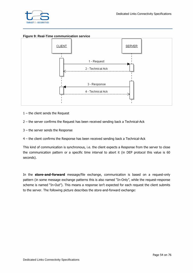
Dedicated Links Connectivity Specifications
Page 54 on 76
Dedicated Links Connectivity Specifications
Figure 9: Real-Time communication service
1 – the client sends the Request
2 – the server confirms the Request has been received sending back a Technical-Ack
3 – the server sends the Response
4 – the client confirms the Response has been received sending back a Technical-Ack
This kind of communication is synchronous, i.e. the client expects a Response from the server to close
the communication pattern or a specific time interval to abort it (in DEP protocol this value is 60
seconds).
In the store-and-forward message/file exchange, communication is based on a request-only
pattern (in some message exchange patterns this is also named “In-Only”, while the request-response
scheme is named “In-Out”). This means a response isn’t expected for each request the client submits
to the server. The following picture describes the store-and-forward exchange:
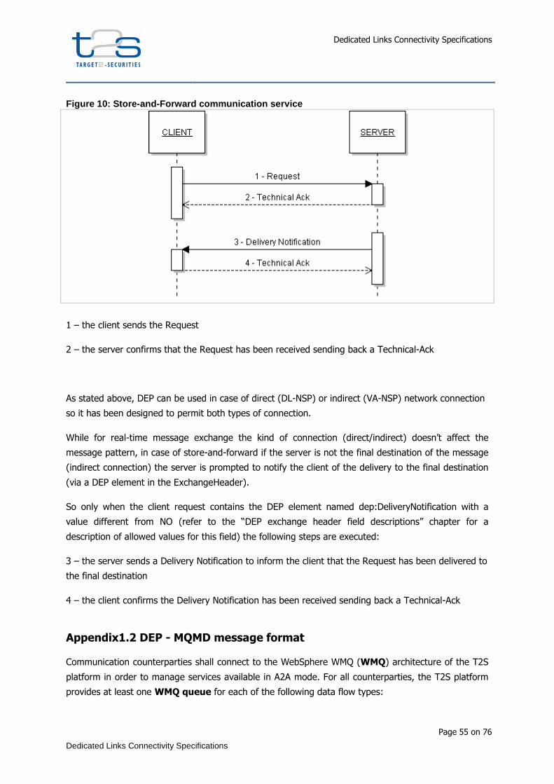
Dedicated Links Connectivity Specifications
Page 55 on 76
Dedicated Links Connectivity Specifications
Figure 10: Store-and-Forward communication service
1 – the client sends the Request
2 – the server confirms that the Request has been received sending back a Technical-Ack
As stated above, DEP can be used in case of direct (DL-NSP) or indirect (VA-NSP) network connection
so it has been designed to permit both types of connection.
While for real-time message exchange the kind of connection (direct/indirect) doesn’t affect the
message pattern, in case of store-and-forward if the server is not the final destination of the message
(indirect connection) the server is prompted to notify the client of the delivery to the final destination
(via a DEP element in the ExchangeHeader).
So only when the client request contains the DEP element named dep:DeliveryNotification with a
value different from NO (refer to the “DEP exchange header field descriptions” chapter for a
description of allowed values for this field) the following steps are executed:
3 – the server sends a Delivery Notification to inform the client that the Request has been delivered to
the final destination
4 – the client confirms the Delivery Notification has been received sending back a Technical-Ack
Appendix1.2 DEP - MQMD message format
Communication counterparties shall connect to the WebSphere WMQ (WMQ) architecture of the T2S
platform in order to manage services available in A2A mode. For all counterparties, the T2S platform
provides at least one WMQ queue for each of the following data flow types:

Dedicated Links Connectivity Specifications
Page 56 on 76
Dedicated Links Connectivity Specifications
• real-time messages
• real-time files
• store-and-forward messages
• store-and-forward files
The T2S middleware and the counterparties manage the data exchange based on WMQ messages,
that consist of a Message Description part (MQMD) and a Message Text part. WMQ RFH2
headers may exist in the WMQ messages but will be ignored by the T2S platform. The usage of other
headers is not allowed.
As previously mentioned, the message structure of DEP uses standard WMQ messages; so, DEP uses
IBM WebSphere WMQ as transport layer for its message primitives. The message text is in XML
format.
Figure 11: WMQ data structure
WMQ Message DescriptorWMQ Message Descriptor
WMQ Message TextWMQ Message Text
Message Type Feedback
Format Application Identity
Message Id and Correlation Id Encoding
Code Character Set Id Report option
Expiry
Exchange Header
Business Envelope
Digital Signature
Exchange Header
Business Envelope
Digital Signature
Figure 11 shows the WMQ format message structure:
• WMQ message descriptor: it contains all the data required to manage the message from
an infrastructure point of view.

Dedicated Links Connectivity Specifications
Page 57 on 76
Dedicated Links Connectivity Specifications
• WMQ message text: it is the information content of the message, formed according to the
DEP structure (detailed in the following sections), i.e.:
• Exchange Header (header of the DEP data structure);
• Business Envelope (its composition in Business File Header and/or Business Application
Header and business document is out-of-scope of this document);
• The digital signature of the technical sender (T2S Platform or DEP counterparties) of
the message. The signature of the Technical Sender is located in the DEP, while the
signature of the Business Sender is located in the Business Application Header (or in the
Business File Header in case of “multi-message”). This Technical Sender signature is
present only if the “Non Repudiation” flag is set in the exchange header of the DEP data
exchange.
Table 10 describes the list of WMQ message standard MQMD header fields, which sender and receiver
have to manage when a message or a file is exchanged, and the contents of the “WMQ Message
Text” part, in order to support the DEP message primitives.
Table 10: WMQ Data Structure
DATA SECTION DESCRIPTION
WMQ Message Description
No particular header (e.g. RFH2) are foreseen.
• MQMD.MsgType: request/reply/report/datagram values are allowed;
• MQMD.Format: e.g. WMQFMT_NONE;
• MQMD.MsgId and CorrelationId;
• MQMD.Encoding;
• MQMD.ApplIdentity;
• MQMD.Feedback;
• MQMD.CodeCharacterSetId;
• MQMD.Report option: set to the value WMQRO_PAN+WMQRO_NAN;
• MQMD.Expiry: this field will be used only for real-time traffic setting the value equal to the real-time time-out timeframe (e.g. 60 seconds). In this way it is possible to avoid unnecessary management of messages already expired.
WMQ Message Text
• Exchange Header section: contains all "service information" needed for the transport layer, exchanged between the DiCoA-DL or VA-NSP and the T2S Platform to manage messages and files flows;
• Business Envelope for business layer: contains the Business Application Header or the File Application Header with document (or document set) section.
• Digital Signature contains the signature at DEP level (signature at business level is, if present, inside the Business Envelope)
Appendix1.2.1 General Rules
The general rules summarized in table 2 should be applied to WMQ messages for the DEP. All other
fields that are not specifically mentioned here should preserve their default values as defined in the
WMQ API or as set as the defaults for the applied WMQ platform.
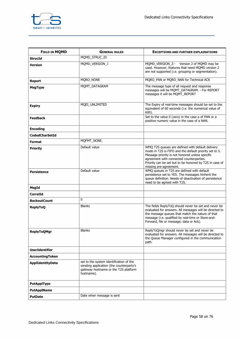
Dedicated Links Connectivity Specifications
Page 58 on 76
Dedicated Links Connectivity Specifications
FIELD IN MQMD GENERAL RULES EXCEPTIONS AND FURTHER EXPLAINATIONS
StrucId MQMD_STRUC_ID
Version MQMD_VERSION_1 MQMD_VERSION_2:· Version 2 of MQMD may be used. However, features that need MQMD version 2 are not supported (i.e. grouping or segmentation).
Report MQRO_NONE MQRO_PAN or MQRO_NAN for Technical ACK
MsgType MQMT_DATAGRAM The message type of all request and response messages will be MQMT_DATAGRAM. - For REPORT messages it will be MQMT_REPORT
Expiry MQEI_UNLIMITED The Expiry of real-time messages should be set to the equivalent of 60 seconds (i.e. the numerical value of 600).
Feedback Set to the value 0 (zero) in the case a of PAN or a positive numeric value in the case of a NAN.
Encoding
CodedCharSetId
Format MQFMT_NONE.
Priority Default value WMQ T2S queues are defined with default delivery mode in T2S is FIFO and the default priority set to 5. Message priority is not honored unless specific agreement with connected counterparties. Priority can be set but to be honored by T2S in case of missing pre-agreement.
Persistence Default value WMQ queues in T2S are defined with default persistence set to YES. The messages hinherit the queue definition. Needs of deactivation of persistence need to be agreed with T2S.
MsgId
CorrelId
BackoutCount 0
ReplyToQ Blanks The fields ReplyToQ should never be set and never be evaluated for answers. All messages will be directed to the message queues that match the nature of that message (i.e. qualified by real-time or Store-and-Forward, file or message; data or Ack).
ReplyToQMgr Blanks ReplyToQmgr should never be set and never be evaluated for answers. All messages will be directed to the Queue Manager configured in the communication path.
UserIdentifier
AccountingToken
ApplIdentityData set to the system identification of the sending application (the counterparty’s gateway hostname or the T2S platform hostname).
PutApplType
PutApplName
PutDate Date when message is sent

Dedicated Links Connectivity Specifications
Page 59 on 76
Dedicated Links Connectivity Specifications
PutTime Time when message is sent
ApplOriginData Blanks
GroupId
MsgSeqNumber
Offset
MsgFlags
OriginalLength
Please note that these regulations might be changed or extended in future versions of DEP.
Appendix1.2.2 Technical Ack Messages
The DEP requires a technical acknowledgment message to be sent for each data exchange
between the T2S platform and its communication counterparties. The technical ack is sent by the
receiver of a DEP message to the sender of the original DEP message. This technical ack is necessary
to confirm the completion of the data exchange.
This technical ack is a WebSphere WMQ report message with type PAN (Positive Application
Notification) or NAN (Negative Application Notification). The receiving counterpart sends back this
acknowledgment when it undertakes the received message (e.g. when it stores the message or it
starts processing it).
The structure of the technical ack is as follows:
1. Technical Acks will get message type MQMT_REPORT.
2. The Feedback field of the MQMD will be set to the value 0 (zero) in case of PAN or to a
positive numeric value in case of NAN.
3. The Application Identity Data field of the MQMD (ApplIdentityData) will be set to the system
identification of the sending application (the counterparty’s gateway hostname or the T2S
platform hostname).
4. The Correlation Id field of the MQMD section will be set to the "Message Id" (MQMD field
MsgId) of the original message.
5. The Message Text part of the WMQ message returns the "Exchange Header" of the original
message, updated as foreseen in the following message patterns description in case of a PAN.
In case of a NAN the field "dep:ErrorDescription" returns an error message.
Refer to Appendix1.4.2-Technical ack/nak management section for additional information.
Appendix1.3 DEP message format

Dedicated Links Connectivity Specifications
Page 60 on 76
Dedicated Links Connectivity Specifications
A valid DEP message is a well-formed XML document, as defined in the W3C specification, meeting
some additional constraints expressed by an XML Schema Definition (XSD, ref. Appendix 1). Every
message presents an XML declaration, which specifies the version of XML being used (e.g.
version=“1.0”), the character encoding (encoding=”UTF-8”) and an XML element which defines the
message primitive.
Diagram 12: Main DEP message primitives
As shown in Diagram 12, the DEP specifies four message primitives, each with a proper XML element
type definition:
• A Request message: the sender uses this message type to send a message/file to a receiver.
This kind of primitive is used both in real-time mode and in store-and-forward mode.
• A Response message: the sender uses this message type to answer a previously received
request. This kind of primitive is used only in real-time mode.
• A TechnicalAck message: this acknowledgement is provided for each data exchange
between the communication counterparties for the confirmation of the completion of the data
exchange. This kind of primitive shall be used both in real-time mode and in store-and-
forward mode. For technical sender non-repudiation functionality, the receiver must sign the
Technical Ack and include the hash of the received message and the relevant timestamp in
the ExchangeHeader.
• A DeliveryNotification message: in the store-and-forward mode this message is used to
inform the DEP sender that a Request message has been delivered to the final destination. In
case of indirect connection scenario, after 10 unsuccessful attempts, the server sends back to

Dedicated Links Connectivity Specifications
Page 61 on 76
Dedicated Links Connectivity Specifications
the original sender a “Delivery Notification Failure” and suspends the sending of the store-
and-forward messages/files to the T2S platform.
• An EnableSnfTraffic message: in case of store-and-forward mode in the indirect scenario
this primitive is used by T2S to inform the NSP that it is ready to receive the store-and-
forward traffic.
• An EnableSnfTrafficAck message: in case of store-and-forward mode in the indirect
scenario this primitive is used by the NSP to reply to the T2S Platform about an
EnableSnfTraffic request result.
• A DisableSnfTraffic message: in case of store-and-forward mode in the indirect scenario
this primitive is used by T2S to inform the NSP that it is not ready to receive the store-and-
forward traffic.
• A DisableSnfTrafficAck message: in case of store-and-forward mode in the indirect
scenario this primitive is used by the NSP to reply to the T2S Platform about DisableSnfTraffic
request result.
• A QuerySnfTraffic message: in case of store-and-forward mode in the indirect scenario this
primitive is used by T2S to check the status of the store-and-forward traffic.
• A QuerySnfTrafficAck message: in case of store-and-forward mode in the indirect scenario
this primitive is used by the NSP to reply to the T2S Platform about the status of the store-
and-forward traffic.
The Exchange Header section (see Diagram 13) contains all the service information needed by the
transport layer, exchanged between the DEP communication counterpart and the T2S platform to
manage messages and files flow.

Dedicated Links Connectivity Specifications
Page 62 on 76
Dedicated Links Connectivity Specifications
Diagram 13: DEP ExchangeHeader type
The BusinessEnvelope section contains business information. This part is not checked or modified by
the NSP or by the T2S middleware and it is delivered unchanged to the receiver.
Appendix1.4 DEP exchange header fields description
As shown in Diagram 13, the ExchangeHeader section contains all the service information needed for
the transport layer, exchanged between DEP communication counterparties to manage messages and
files flows, in real-time or store-and-forward mode.
As specified in the XSD (XML Schema Definition) of the DEP Exchange Header, provided in “Exchange
Header XSD and message examples”, this section contains many mandatory or optional fields.

Dedicated Links Connectivity Specifications
Page 63 on 76
Dedicated Links Connectivity Specifications
The DEP uses a technical header (ExchangeHeader) to convey technical information to the
counterpart. This technical information is used for many purposes, i.e.:
• Addressing (dep:Sender and dep:Receiver);
• Selecting Message/File channel to use (dep:TechnicalServiceId);
• Message/File identifier (dep:T2SActorMessageId, dep:T2SMessageId);
• Timestamps (dep:SendTimestamp, dep:ReceiveTimestamp, dep:EntryTimestamp);
• Function’s flags (dep:DeliveryNotification, dep:NonRepudiationExchange and
dep:Compression);
• Message/File security (dep:MessageDigest);
• Message/File flow control (dep:ExchangeStatus, dep:ErrorDescription).
Table 11 includes an exhaustive list of the available tags and their descriptions, specifying allowed
values and providing an example for the main tags.
Table 11: DEP ExchangeHeader Fields.
TAG NAME TAG DESCRIPTION / ALLOWED VALUES
EXAMPLE
dep:Version
<mandatory tag>
Version of Data Exchange Protocol. Enumeration with fixed value “0.2”
<dep:Version> 0.2
</dep:Version>
dep:Sender
<mandatory tag>
Identification for T2S Technical Sender that sends the message. Restriction is set on base type "string [100]".
<dep:Sender> cn=t2sappl1, o=t2sprod
</dep:Sender>
dep:Receiver
<mandatory tag>
Identification for T2S Technical Receiver that receives the message.
Restriction is set on base type "string [100]".
<dep:Receiver> cn=t2s-cust1, o=nsp-name1
</dep:Receiver>
dep:TechnicalServiceID
<mandatory tag>
Name of the service used to send messages and files, formed by the DEP counterpart name, the message pattern and the environment of reference.
Specifying a message pattern, it’s possible to manage a message or a file as a payload of the DEP message. Message pattern means the following:
• MSGRT: Real Time Message;
• MSGSNF: Store & Forward Message;
• FILERT: Real Time File;
• FILESNF: Store & Forward File.
Restriction is set on base type "string [60]", with expression in the format:
VA-NSP/DiCoA-DL Name+ "." + <msg-pattern> + "." + <environment>
where <msg-pattern> is one of: MSGRT MSGSNF FILERT FILESNF and <environment> is one of: INTEG,IAC,EAC,UTEST,MIG1,MIG2,PROD
<dep:TechnicalServiceId> nsp-name1.MSGRT.PROD
</dep:TechnicalServiceId>

Dedicated Links Connectivity Specifications
Page 64 on 76
Dedicated Links Connectivity Specifications
dep:RequestType
<mandatory tag>
Type of request, to classify message content.
In case of different request types in the same BusinessEnvelope, the "T2SRequest" value shall be used as RequestType
Restriction is set on base type "string [100]".
<dep:RequestType> T2SRequest
</dep: RequestType >
dep:CommunicationID
<minOccurs=”0”>
Unique message identifier assigned by the T2S counterpart (at DEP transport level)l
Restriction is set on base type "string [100]".
<dep:CommunicationId> nsp-name1.gtw134567. 20100908185555.123456
</dep:CommunicationId>
dep:T2SMessageId
<minOccurs=”0”>
Unique message identifier generated by T2S Platform Restriction is set on base type "string [100]".
<dep:T2SMessageId> T2S.MSGRT.NSPname1.20110101000000.000001
</dep:T2SMessageId>
dep:T2SActorMessageId
<minOccurs=”0”>
Unique message identifier generated at T2S actor site Restriction is set on base type "string [100]".
<dep:T2SActorMessageId> T2SActorGateway1.20100908175531.123456
</dep:T2SActorMessageId>
dep:EntryTimestamp
<minOccurs=”0”>
Timestamp of the NSP's gateway reception, based on UTC time
Restriction is set on base type "dateTime".
<dep:EntryTimestamp> 2011-01-01T00:00:00
</dep:EntryTimestamp>
dep:SendTimestamp
<mandatory tag>
Timestamp of the sending of message, based on UTC time
Restriction is set on base type "dateTime".
<dep:SendTimestamp> 2011-01-01T00:00:00
</dep:SendTimestamp>
dep:ReceiveTimestamp
<minOccurs=”0”>
Timestamp of the receiving of message, based on UTC time
Restriction is set on base type "dateTime".
<dep:ReceiveTimestamp> 2011-01-01T00:00:01
</dep:ReceiveTimestamp>
dep:PDMHistory
<minOccurs=”0”>
Only for store-and-forward, Timestamp's list of the attempts of the delivery of the message, based on UTC time.
This list contains a sequence of SendTimestamp entries. It also contains for each timestamp an optional AdditionalInfo.
This is a complex type tag based on a sequence of maximum occurrences, each one containing two elements:
• TimeStamp, a mandatory tag with base type dateTime;
• AdditionalInfo, an optional tag with restriction set on base type "string [100]".
<dep:PDMHistory> <dep:TimeStamp>
2011-01-01T00:00:00 </dep:TimeStamp> <dep:TimeStamp>
2011-02-14T00:10:01 </dep:TimeStamp> <dep:AdditionalInfo>
Annotation on 2th timestamp entry
</dep:AdditionalInfo>
</dep:PDMHistory>
dep:DeliveryMode
<mandatory tag>
Identification of real time or store-and-forward exchange.
Enumeration with possible values:
• “RT” for Real-Time;
• “SF” for Store-and-forward.
<dep:DeliveryMode> RT
</dep:DeliveryMode>

Dedicated Links Connectivity Specifications
Page 65 on 76
Dedicated Links Connectivity Specifications
dep:DeliveryNotification
<minOccurs=”0”>
Delivery notification management; this field has to be set only in the case of store-and-forward mode for indirect connection.
The following values are foreseen:
• “YES”: the delivery notification is requested always
• “FAIL”: the delivery notification is requested only in case of failure
• “NO”: the delivery notification is not requested (default value)
Restriction is set on base type "string".
<dep:DeliveryNotification> FAIL
</dep:DeliveryNotification>
dep:
NonRepudiationExchange
<mandatory tag>
Flag that indicates if the non-repudiation is requested or not
Enumeration with possible values: YES or NO.
<dep:NonRepudiationExchange> NO
</dep:NonRepudiationExchange>
dep:Compression
<mandatory tag>
Flag that indicates the algorithm used to compress the payload or "NO" (if compression is not used) Enumeration with possible values “NONE” or “ZIP”.
<dep:Compression> ZIP
</dep:Compression>
dep:ExchangeStatus
<mandatory tag>
Status of the exchange: "OK" in the case of a successful exchange "KO" in case of failure
This element must be present in DEP technical ack messages and in Response messages of R-T (message and file) exchange.
Enumeration with possible values:
• "OK" in the case of successful exchange
• "KO" in case of failure
<dep:ExchangeStatus> OK
</dep:ExchangeStatus>
dep:ErrorDescription
<minOccurs=”0”>
Description of the error occurred during the exchanging process (tag has to be set only if tag dep:ExchangeStatus has value "KO" )
This is a complex type tag based on two elements:
• ErrorCode, a mandatory tag with base type string and a validation pattern “T2S[0-9]{3}E”.
• AdditionalInfo, an optional tag with restriction set on base type "string [200]".
<dep:ErrorDescription> <dep:ErrorCode>
T2S040E </dep:ErrorCode> <dep:AdditionalInfo>
Message expired. Receiver has not been connected for 14 days.
</dep:AdditionalInfo> </dep:ErrorDescription>
dep:MessageDigest
<minOccurs=”0”>
Used only in Technical Ack primitive when the NonRepudiationExchange flag has been set.
The digest has to be calculated based on the received DEP Exchange Header and Business Envelope.
Restriction is set on base type "string [1024]".
In the DEP data can be exchanged as a message or a file. From a DEP point of view the distinction
between a file or a message is based only on the size of the transported Business Envelope. There is
no relationship between the message/file term used at DEP level and the message/file term used at
business level.
The channel through which data is exchanged, both for messages and files, defines the maximum size
of the Business Envelope part of the DEP message (size is calculated without considering the
BusinessEnvelope tags). Size limits for each channel are summarized in Table 12.
Dedicated Links Connectivity Specifications
Page 66 on 76
Dedicated Links Connectivity Specifications
Table 12: Size limits for the various channels.
MINIMUM LENGTH MAXIMUM LENGTH
Message channel n.a. 32 KB
File channel n.a. 32 MB
Appendix1.4.1 Non repudiation management
The non-repudiation feature of DEP is used to provide both sender and receiver of DEP messages with
a guarantee that both the emission and the reception of such messages cannot be repudiated. Non-
repudiation in DEP is based on the exchange of electronic signatures which include essential parts of
the DEP message. Non-repudiation in DEP relies on the so-called technical or transport signature. DEP
messages may also carry business signatures that only refer to the Business Envelope content of
messages. Business signatures have no function with respect to DEP non-repudiation.
Signature management is based on the XML Advanced Electronic Signature (XAdES) standard. In
particular, the DEP adopts the XAdES-BES (Basic Electronic Signature) format for signature of DEP
message/file exchange.
The counterparties using DEP shall manage the non-repudiation flag on exchanging of incoming and
outgoing messages/files. In the following is described the process that the T2S Platform and
counterparties shall manage in case of non-repudiation (dep:NonRepudiationExchange=YES). The
sender of a message will decide whether to enable non-repudiation or not on the basis of the business
requirements for that message. This decision is out of scope of DEP.
If the non-repudiation is requested for a message/file:
• The sending part (e.g. T2S) shall sign the message and insert the electronic signature into the
Signature element of the DEP request or response message.
• The receiving part (e.g. a counterparty) shall verify the validity of the signature and send back
an error message (NAN Technical ack) if the check fails (i.e. Code T2S999E in case of other
errors, appropriate error information is provided in th NAN), otherwise, the receiving part shall
create a PAN technical ack.
• Sign the message and insert the electronic signature into the Signature element.
• The sending part shall check the validity of the signature added to the Technical Ack and
store the message.
It is the responsibility of all counterparties to keep enough data of the messages (including its
signatures) and information used during signature validation to provide evidence of the correct issuing
and validation of signatures when required. The extent of such evidence and the time frame to keep
it, is beyond the scope of DEP.

Dedicated Links Connectivity Specifications
Page 67 on 76
Dedicated Links Connectivity Specifications
The technical signature shall be an XAdES-BES signature. It shall follow the manifest signature form
the W3C XML Signature Syntax and Processing recommendation (http://www.w3.org/TR/xmldsig-core/,
section 2.3).
The signature shall contain:
1. A single Reference in the SignedInfo that points to the Manifest.
2. A Manifest structure in its Object container. The Manifest itself will contain References as
follows:
o For Technical ack:
1. A Reference with empty URI covering the technical Ack itself containing its
DigestValue.
2. One Reference covering the BusinessEnvelope of the message or file for
which the technical ack was generated containing its DigestValue.
o For Request/Response:
1. A Reference with empty URI covering the Request/Response itself containing
its DigestValue.
The creation of a signature requires that the signer first obtain the digests of all messages contents
that should be included in the signature. As the final step, the signature structure shall be created and
signed.
On the receiving side, the process of validation depends on the responsible counterparty. Like signing,
validation will also be performed in two steps:
1. All receiving parties shall validate the signature as a fundamental step.
2. The validity of all contained digests shall be checked.
Parties that directly communicate using DEP are in possession of the complete DEP messages. It is
their responsibility to check all digests contained in the signature.
Downstream recipients of the contained Business Envelope are not able to check all DEP message
contents. However, it is their responsibility to check the validity of the digests of the affected Business
Envelope.
The following sample shows the contents of a Technical ack signature: <ds:Signature xmlns:ds="http://www.w3.org/2000/09/x mldsig#" Id="Signature-GS3PV"> <ds:SignedInfo> <ds:CanonicalizationMethod Algorithm="http://www.w 3.org/TR/2001/REC-xml-c14n-20010315" /> <ds:SignatureMethod Algorithm="http://www.w3.org/2 001/04/xmldsig-more#rsa-sha256" /> <ds:Reference URI="#Manifest"> <ds:Transforms> <ds:Transform Algorithm="http://www.w3.org/TR/200 1/REC-xml-c14n-20010315" /> </ds:Transforms> <ds:DigestMethod Algorithm="http://www.w3.org/2001 /04/xmlenc#sha256"/> <ds:DigestValue>...</ds:DigestValue>
Dedicated Links Connectivity Specifications
Page 68 on 76
Dedicated Links Connectivity Specifications
</ds:Reference> </ds:SignedInfo> <ds:SignatureValue>...</ds:SignatureValue> <ds:KeyInfo> <ds:X509Data> <ds:X509Certificate>...</ds:X509Certificate> </ds:X509Data> </ds:KeyInfo> <Object xmlns="http://www.w3.org/2000/09/xmldsig#" > <QualifyingProperties xmlns="http://uri.etsi.org/0 1903/v1.4.1#" Target="#Signature-GS3PV"> <UnsignedProperties> <UnsignedSignatureProperties> <SignatureTimeStamp Id="SignatureTimeStamp"> <CanonicalizationMethod xmlns="http://www.w3.org /2000/09/xmldsig#" Algorithm="http://www.w3.org/TR/2001/REC-xml-c14n-2 0010315" /> <EncapsulatedTimeStamp Encoding="http://uri.etsi.org/01903/v1.2.2#DER">... </EncapsulatedTimeStamp> </SignatureTimeStamp> </UnsignedSignatureProperties> </UnsignedProperties> </QualifyingProperties> <Manifest Id="Manifest"> <Reference URI=""> <Transforms> <Transform Algorithm=http://www.w3.org/2000/09/xmldsig#enve loped-signature/> <Transform Algorithm="http://www.w3.org/TR/2001/12/REC-xml- c14n-20010315"/> </Transforms> <DigestMethod Algorithm="http://www.w3.org/2001/04/xmlenc#sha25 6"/> <DigestValue>...</DigestValue> </Reference> <Reference URI="BusinessEnvelope"> <DigestMethod Algorithm="http://www.w3.org/2001/04/xmlenc#sha25 6"/> <DigestValue>...</DigestValue> </Reference> </Manifest> </Object>
</ds:Signature>
Appendix1.4.2 Technical ack/nak management
The receiver provides a Technical Ack for each data exchange with the sender, for confirmation of the
data exchange completion.
The receiver manages the technical acknowledgement process as follows. The Technical Ack is a
WebSphere WMQ report message with type PAN (Positive Application Notification) or NAN (Negative
Application Notification). The receiving WebSphere WMQ application (e.g. the T2S middleware
component) sends this report back when undertaking a message (i.e. when the message is stored or
processed setting the dep:ReceiveTimestamp). Section Appendix1.3-DEP message format describes
the structure of the Technical Ack.
The Technical Ack, for store-and-forward communication, shall be returned to the DEP sender within a
time-frame of 10 minutes13.
For real-time communication, no specific actions are required for timing issues, owing to the time-out
management mechanism. For store-and-forward incoming messages, in case that the time-out for the
Technical Ack is exceeded, the DEP sender re-sends the message including in the ExchangeHeader
13 This value can be configured.
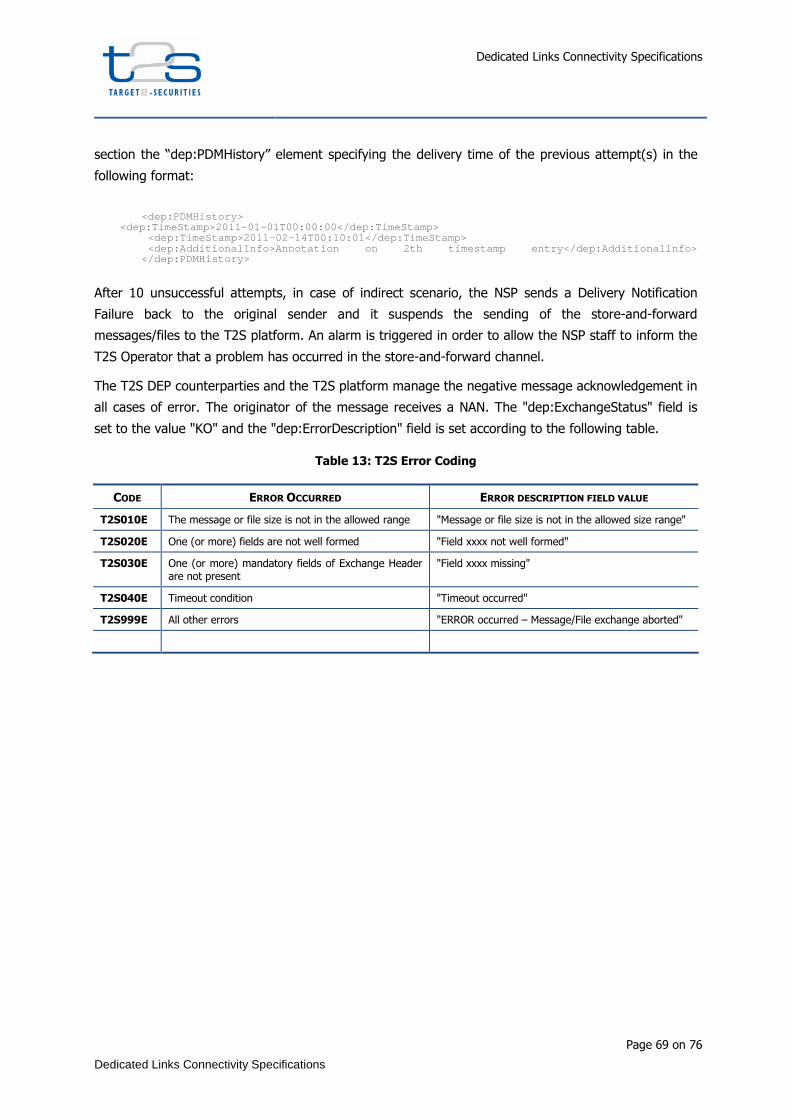
Dedicated Links Connectivity Specifications
Page 69 on 76
Dedicated Links Connectivity Specifications
section the “dep:PDMHistory” element specifying the delivery time of the previous attempt(s) in the
following format:
<dep:PDMHistory>
<dep:TimeStamp>2011-01-01T00:00:00</dep:TimeSta mp> <dep:TimeStamp>2011-02-14T00:10:01</dep:TimeStamp> <dep:AdditionalInfo>Annotation on 2th timestamp en try</dep:AdditionalInfo> </dep:PDMHistory>
After 10 unsuccessful attempts, in case of indirect scenario, the NSP sends a Delivery Notification
Failure back to the original sender and it suspends the sending of the store-and-forward
messages/files to the T2S platform. An alarm is triggered in order to allow the NSP staff to inform the
T2S Operator that a problem has occurred in the store-and-forward channel.
The T2S DEP counterparties and the T2S platform manage the negative message acknowledgement in
all cases of error. The originator of the message receives a NAN. The "dep:ExchangeStatus" field is
set to the value "KO" and the "dep:ErrorDescription" field is set according to the following table.
Table 13: T2S Error Coding
CODE ERROR OCCURRED ERROR DESCRIPTION FIELD VALUE
T2S010E The message or file size is not in the allowed range "Message or file size is not in the allowed size range"
T2S020E One (or more) fields are not well formed "Field xxxx not well formed"
T2S030E One (or more) mandatory fields of Exchange Header are not present
"Field xxxx missing"
T2S040E Timeout condition "Timeout occurred"
T2S999E All other errors "ERROR occurred – Message/File exchange aborted"
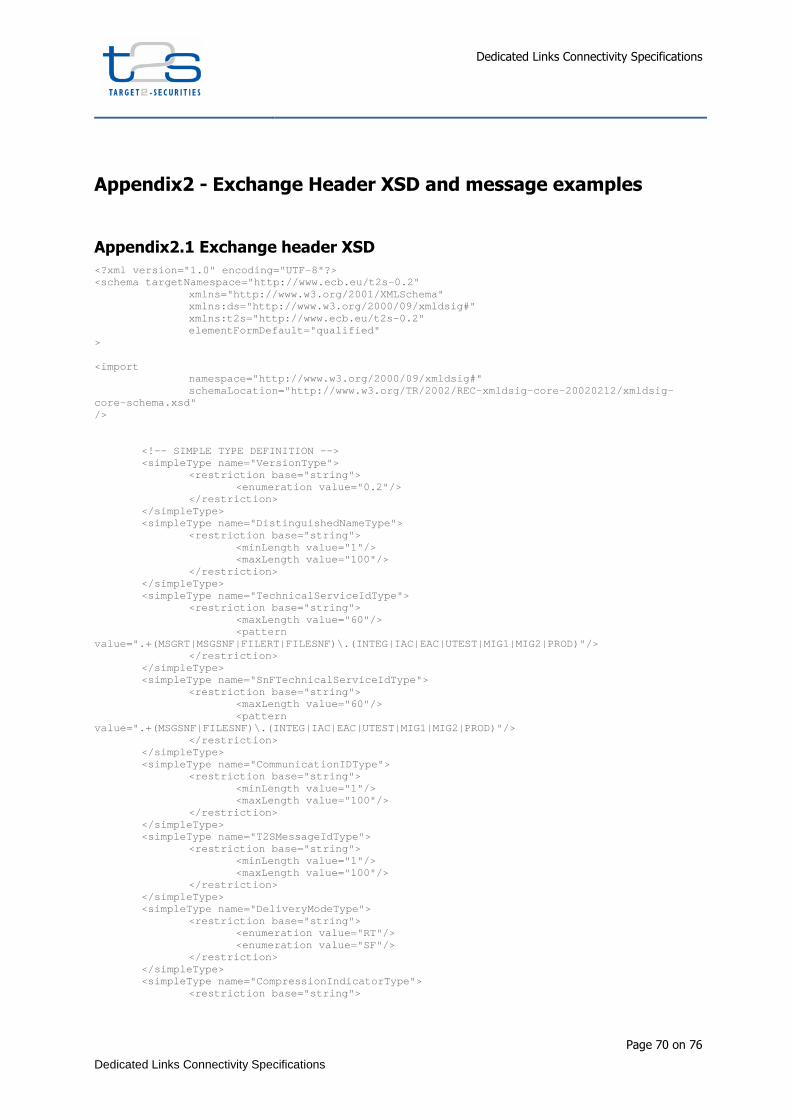
Dedicated Links Connectivity Specifications
Page 70 on 76
Dedicated Links Connectivity Specifications
Appendix2 - Exchange Header XSD and message examples
Appendix2.1 Exchange header XSD
<?xml version="1.0" encoding="UTF-8"?> <schema targetNamespace="http://www.ecb.eu/t2s-0.2" xmlns="http://www.w3.org/2001/XMLSchema" xmlns:ds="http://www.w3.org/2000/09/xmldsig#" xmlns:t2s="http://www.ecb.eu/t2s-0.2" elementFormDefault="qualified" > <import namespace="http://www.w3.org/2000/09/xmldsig#" schemaLocation="http://www.w3.org/TR/2002/REC-xml dsig-core-20020212/xmldsig-core-schema.xsd" /> <!-- SIMPLE TYPE DEFINITION --> <simpleType name="VersionType"> <restriction base="string"> <enumeration value="0.2"/> </restriction> </simpleType> <simpleType name="DistinguishedNameType"> <restriction base="string"> <minLength value="1"/> <maxLength value="100"/> </restriction> </simpleType> <simpleType name="TechnicalServiceIdType"> <restriction base="string"> <maxLength value="60"/> <pattern value=".+(MSGRT|MSGSNF|FILERT|FILESNF)\.(INTEG|IAC| EAC|UTEST|MIG1|MIG2|PROD)"/> </restriction> </simpleType> <simpleType name="SnFTechnicalServiceIdType"> <restriction base="string"> <maxLength value="60"/> <pattern value=".+(MSGSNF|FILESNF)\.(INTEG|IAC|EAC|UTEST|MIG 1|MIG2|PROD)"/> </restriction> </simpleType> <simpleType name="CommunicationIDType"> <restriction base="string"> <minLength value="1"/> <maxLength value="100"/> </restriction> </simpleType> <simpleType name="T2SMessageIdType"> <restriction base="string"> <minLength value="1"/> <maxLength value="100"/> </restriction> </simpleType> <simpleType name="DeliveryModeType"> <restriction base="string"> <enumeration value="RT"/> <enumeration value="SF"/> </restriction> </simpleType> <simpleType name="CompressionIndicatorType"> <restriction base="string">
Dedicated Links Connectivity Specifications
Page 71 on 76
Dedicated Links Connectivity Specifications
<enumeration value="NONE"/> <enumeration value="ZIP"/> </restriction> </simpleType> <simpleType name="TimestampType"> <restriction base="dateTime"/> </simpleType> <simpleType name="SnFQueueManagerNameType"> <restriction base="string"> <minLength value="1"/> <maxLength value="48"/> </restriction> </simpleType> <simpleType name="SnFQueueNameType"> <restriction base="string"> <minLength value="1"/> <maxLength value="48"/> </restriction> </simpleType> <simpleType name="SnFStatusType"> <restriction base="string"> <enumeration value="FAILED"/> <enumeration value="ACTIVATED"/> <enumeration value="DEACTIVATED"/> </restriction> </simpleType> <simpleType name="NonRepudiationType"> <restriction base="string"> <enumeration value="YES"/> <enumeration value="NO"/> </restriction> </simpleType> <simpleType name="ReasonType"> <restriction base="string"> <minLength value="1"/> <maxLength value="100"/> </restriction> </simpleType> <simpleType name="ErrorCodeType"> <restriction base="string"> <pattern value="T2S[0-9]{3}E"/> </restriction> </simpleType> <simpleType name="AdditionalInfoType"> <restriction base="string"> <minLength value="1"/> <maxLength value="200"/> </restriction> </simpleType> <simpleType name="T2SActorMessageIdType"> <restriction base="string"> <minLength value="1"/> <maxLength value="100"/> </restriction> </simpleType> <simpleType name="MessageDigestType"> <restriction base="string"> <minLength value="1"/> <maxLength value="1024"/> </restriction> </simpleType> <simpleType name="ExchangeStatusType"> <restriction base="string"> <enumeration value="OK"/> <enumeration value="KO"/> </restriction> </simpleType> <simpleType name="PDMAnnotationType"> <restriction base="string"> <minLength value="1"/> <maxLength value="100"/>
Dedicated Links Connectivity Specifications
Page 72 on 76
Dedicated Links Connectivity Specifications
</restriction> </simpleType> <simpleType name="DeliveryNotificationMode"> <restriction base="string"> <enumeration value="YES"/> <enumeration value="NO"/> <enumeration value="FAIL"/> </restriction> </simpleType> <simpleType name="RequestType"> <restriction base="string"> <minLength value="1"/> <maxLength value="30"/> </restriction> </simpleType> <!-- COMPLEX TYPE DEFINITION --> <complexType name="SnFServiceType"> <sequence> <element name="Name" type="t2s:SnFTechnicalServi ceIdType"/> <element name="DestQmanagerName" type="t2s:SnFQu eueManagerNameType"/> <element name="DestQueueName" type="t2s:SnFQueue NameType"/> </sequence> </complexType> <complexType name="SnFQueryServiceType"> <sequence> <element name="Name" type="t2s:SnFTechnicalServi ceIdType"/> </sequence> </complexType> <complexType name="SnFServiceAckType"> <complexContent> <extension base="t2s:SnFServiceType"> <sequence> <element name="Status" type="t2s:SnFStatusType "/> <element name="Reason" type="t2s:ReasonType" minOccurs="0"/> </sequence> </extension> </complexContent> </complexType> <complexType name="SnFTrafficCommandType"> <sequence> <element name="Service" type="t2s:SnFServiceType " maxOccurs="unbounded"/> </sequence> </complexType> <complexType name="SnFTrafficQueryCommandType"> <sequence> <element name="Service" type="t2s:SnFQueryServic eType"/> </sequence> </complexType> <complexType name="SnFTrafficCommandAckType"> <sequence> <element name="Service" type="t2s:SnFServiceAckT ype" maxOccurs="unbounded"/> </sequence> </complexType> <complexType name="ErrorDescriptionType"> <sequence> <element name="ErrorCode" type="t2s:ErrorCodeTyp e"/> <element name="AdditionalInfo" type="t2s:Additio nalInfoType" minOccurs="0"/> </sequence> </complexType> <complexType name="PDMType"> <sequence minOccurs="1" maxOccurs="10"> <element name="TimeStamp" type="t2s:TimestampTyp e"/> <element name="AdditionalInfo" type="t2s:PDMAnno tationType" minOccurs="0"/>

Dedicated Links Connectivity Specifications
Page 73 on 76
Dedicated Links Connectivity Specifications
</sequence> </complexType> <complexType name="ExchangeHeaderType"> <sequence> <element name="Version" type="t2s:VersionType"> <annotation> <documentation>Version of Data Exchange Protocol</documentation> </annotation> </element> <element name="Sender" type="t2s:DistinguishedNa meType"> <annotation> <documentation> Identification for T2S Technical Sender that sends the message </documentation> </annotation> </element> <element name="Receiver" type="t2s:Distinguished NameType"> <annotation> <documentation> Identification for T2S Technical Receiver that receives the message </documentation> </annotation> </element> <element name="TechnicalServiceId" type="t2s:Tec hnicalServiceIdType"> <annotation> <documentation> Name of the service used to send messages and files VA-NSP/DiCoA-DL Name+ "." + <msg-pattern&g t; + "." + <environment> where <msg-pattern> is one of: MSGRT MS GSNF FILERT FILESNF and <environment> is one of: I NTEG,IAC,EAC,UTEST,MIG1,MIG2,PROD. </documentation> </annotation> </element> <element name="RequestType" type="t2s:RequestTyp e"> <annotation> <documentation> Type of the request, to classify message cont ent. In case of different request types in the sam e BusinessEnvelope, the "T2SRequest" value shall be u sed as RequestType </documentation> </annotation> </element> <element name="CommunicationId" type="t2s:Commun icationIDType" minOccurs="0"> <annotation> <documentation> Unique message identifier assigned by the T2S counterpart (at DEP transport level) </documentation> </annotation> </element> <element name="T2SMessageId" type="t2s:T2SMessag eIdType" minOccurs="0"> <annotation> <documentation> Unique message identifier generated by T2S Platform </documentation> </annotation> </element> <element name="T2SActorMessageId" type="t2s:T2SA ctorMessageIdType" minOccurs="0"> <annotation> <documentation>
Dedicated Links Connectivity Specifications
Page 74 on 76
Dedicated Links Connectivity Specifications
Unique message identifier generated at T2S ac tor site </documentation> </annotation> </element> <element name="EntryTimestamp" type="t2s:Timesta mpType" minOccurs="0"> <annotation> <documentation> Timestamp of the NSP's gateway reception, bas ed on UTC time </documentation> </annotation> </element> <element name="SendTimestamp" type="t2s:Timestam pType"> <annotation> <documentation> Timestamp of the sending of message, based on UTC time </documentation> </annotation> </element> <element name="ReceiveTimestamp" type="t2s:Times tampType" minOccurs="0"> <annotation> <documentation> Timestamp of the receiving of message, based on UTC time </documentation> </annotation> </element> <element name="PDMHistory" type="t2s:PDMType" mi nOccurs="0"> <annotation> <documentation> Timestamp's list of the attempting of the deli very of the message, based on UTC time. This list contains a sequence of SendTimestamp entries. </documentation> </annotation> </element> <element name="DeliveryMode" type="t2s:DeliveryM odeType"> <annotation> <documentation> Identification of real time or store-and-forwa rd exchange </documentation> </annotation> </element> <element name="DeliveryNotification" type="t2s:D eliveryNotificationMode" minOccurs="0"> <annotation> <documentation> Delivery notification management. This field has to be set only in the case of store-and-forward mode. The following values are foreseen: YES: the delivery notification is requested a lways FAIL: the delivery notification is requested only in case of failure NO: the delivery notification is not requeste d (this is the DEFAULT value) </documentation> </annotation> </element> <element name="NonRepudiationExchange" type="t2s :NonRepudiationType"> <annotation> <documentation> Flag that indicates if the non-repudiation is requested or not </documentation> </annotation> </element> <element name="Compression" type="t2s:Compressio nIndicatorType"> <annotation>
Dedicated Links Connectivity Specifications
Page 75 on 76
Dedicated Links Connectivity Specifications
<documentation> Flag that indicates the algorithm used to comp ress the payload or "NONE" (if compression is not used) </documentation> </annotation> </element> <element name="ExchangeStatus" type="t2s:Exchang eStatusType" minOccurs="0"> <annotation> <documentation> Status of the exchange: "OK" in the case of a successful exchange "KO" in case of failure This element must be present in DEP technical ack messages and in Response messages of R-T (message a nd file) exchange. </documentation> </annotation> </element> <element name="ErrorDescription" type="t2s:Error DescriptionType" minOccurs="0"> <annotation> <documentation> Description of the error occurred during the e xchanging </documentation> </annotation> </element> <element name="MessageDigest" type="t2s:MessageD igestType" minOccurs="0"> <annotation> <documentation> Digest of the Message/File exchanged (The dige st has to be applied to the DEP Exchange Header and to the Bu siness Envelope) This element is used only in Technical Ack pri mitive, when DEP:NonRepudiationExchange flag has been set. The digest has to be based on the received DEP Exchange Header and Business Envelope. </documentation> </annotation> </element> </sequence> </complexType> <complexType name="BusinessEnvelopeType"> <complexContent> <extension base="anyType"/> </complexContent> </complexType> <complexType name="ExchangeEnvelopeType"> <sequence> <element name="ExchangeHeader" type="t2s:Exchang eHeaderType"/> <element name="BusinessEnvelope" type="t2s:Busin essEnvelopeType"/> <element ref="ds:Signature" minOccurs="0"/> </sequence> </complexType> <complexType name="TechnicalAckType"> <sequence> <element name="ExchangeHeader" type="t2s:Exchang eHeaderType"/> <element ref="ds:Signature" minOccurs="0"/> </sequence> </complexType> <complexType name="DeliveryNotificationType"> <sequence> <element name="ExchangeHeader" type="t2s:Exchang eHeaderType"/> <element ref="ds:Signature" minOccurs="0"/> </sequence> </complexType>

Dedicated Links Connectivity Specifications
Page 76 on 76
Dedicated Links Connectivity Specifications
<!-- ELEMENT TYPE DEFINITION --> <element name="Request" type="t2s:ExchangeEnvelope Type"/> <element name="Response" type="t2s:ExchangeEnvelop eType"/> <element name="TechnicalAck" type="t2s:TechnicalAc kType"/> <element name="DeliveryNotification" type="t2s:Del iveryNotificationType"/> <element name="EnableSnfTraffic" type="t2s:SnFTraf ficCommandType"/> <element name="DisableSnfTraffic" type="t2s:SnFTra fficCommandType"/> <element name="QuerySnfTraffic" type="t2s:SnFTraff icQueryCommandType"/> <element name="EnableSnfTrafficAck" type="t2s:SnFT rafficCommandAckType"/> <element name="DisableSnfTrafficAck" type="t2s:SnF TrafficCommandAckType"/> <element name="QuerySnfTrafficAck" type="t2s:SnFTr afficCommandAckType"/> </schema>
Appendix2.2 Message Examples


![[RTF]d1lge852tjjqow.cloudfront.netd1lge852tjjqow.cloudfront.net/CIK-0001385157/9ee1b2e7-1b...Use these links to rapidly review the document HYPERLINK "# TE CONNECTIVITY LTD. TABLE](https://img.pdfslide.us/doc/110x75/5b2b27be7f8b9a9c648b4aef/rtf-these-links-to-rapidly-review-the-document-hyperlink-te-connectivity-ltd.jpg)