Embed Size (px)
Citation preview
DECswitch 900EF Router
Installation and ConfigurationPart Number: EK-DEFBA-DN-B01
December 1996
This book explains how to install and configure the DECswitch 900EF module.
Revision/Update Information: This is a revised document.

Digital Equipment Corporation makes no representations that the use of its products in the manner described in this publication will not infringe on existing or future patent rights, nor do the descriptions contained in this publication imply the granting of licenses to make, use, or sell equipment or software in accordance with the description.
Possession, use, or copying of the software described in this publication is authorized only pursuant to a valid written license from Digital or an authorized sublicensor.
© Digital Equipment Corporation 1996. All rights reserved. Printed in U.S.A
The following are trademarks of Digital Equipment Corporation: DEC, DEChub, DECnet, DECswitch, DECconnect, Digital, MultiSwitch, RouteAbout, ThinWire, VAX, VMS, clearVISN, and the Digital logo.
The following are third-party trademarks:AppleTalk is a registered trademark of Apple Computer, Inc.Novell and IPX are registered trademarks of Novell, Inc.
All other trademarks and registered trademarks are the property of their respective holders.
FCC Notice — Class A Computing Device:This equipment generates, uses, and may emit radio frequency energy. The equipment has been type tested and found to comply with the limits for a Class A digital device pursuant to Part 15 of FCC rules, which are designed to provide reasonable protection against such radio frequency interference. Operation of this equipment in a residential area may cause interference in which case the user at his own expense will be required to take whatever measures may be required to correct the interference. Any modifications to this device - unless expressly approved by the manufacturer - can void the user's authority to operate this equipment under part 15 of the FCC rules.VCCI Notice — Class 1 Computing Device:This equipment is in the 1st Class category (information equipment to be used in commercial and/or industrial areas) and conforms to the standards set by the Voluntary Control Council for Interference by Data Processing Equipment and Electronic Office Machines aimed at preventing radio interference in commercial and/or industrial areas. Consequently, when used in a residential area or in an adjacent area thereto, radio interference may be caused to radios and TV receivers. Read the instructions for correct handling. CE Notice — Class A Computing Device:Warning!This is a Class A product. In a domestic environment, this product may cause radio interference, in which case the user may be required to take adequate measures.Achtung!Dieses ist ein Gerät der Funkstörgrenzwertklasse A. In Wohnbereichen können bei Betrieb dieses Gerätes Rundfunkstörungen auftreten, in welchen Fällen der Benutzer für entsprechende Gegenmaßnahmen verantwortlich ist.Attention!Ceci est un produit de Classe A. Dans un environment domestique, ce produit risque de créer des interférences radioélectriques, il appartiendra alors à l’utilisateur de prendre les mesures spécifiques appropriées.
iii
Contents
Preface
Overview . . . . . . . . . . . . . . . . . . . . . . . . . . . . . . . . . . . . . . . . . . . . . . . . . . . . . . . . . . . . . . . . . . . . . ixPurpose of This Document . . . . . . . . . . . . . . . . . . . . . . . . . . . . . . . . . . . . . . . . . . . . . . . . . . . . ixIntended Audience . . . . . . . . . . . . . . . . . . . . . . . . . . . . . . . . . . . . . . . . . . . . . . . . . . . . . . . . . . ix
Organization. . . . . . . . . . . . . . . . . . . . . . . . . . . . . . . . . . . . . . . . . . . . . . . . . . . . . . . . . . . . . . . . . . . .xConventions . . . . . . . . . . . . . . . . . . . . . . . . . . . . . . . . . . . . . . . . . . . . . . . . . . . . . . . . . . . . . . . . . . . xi
Overview. . . . . . . . . . . . . . . . . . . . . . . . . . . . . . . . . . . . . . . . . . . . . . . . . . . . . . . . . . . . . . . . . . xiAssociated Documents . . . . . . . . . . . . . . . . . . . . . . . . . . . . . . . . . . . . . . . . . . . . . . . . . . . . . . . . . . .xiiCorrespondence . . . . . . . . . . . . . . . . . . . . . . . . . . . . . . . . . . . . . . . . . . . . . . . . . . . . . . . . . . . . . . . xiv
Documentation Comments . . . . . . . . . . . . . . . . . . . . . . . . . . . . . . . . . . . . . . . . . . . . . . . . . . . xivOnline Services . . . . . . . . . . . . . . . . . . . . . . . . . . . . . . . . . . . . . . . . . . . . . . . . . . . . . . . . . . . . xiv
How to Order Additional Documentation . . . . . . . . . . . . . . . . . . . . . . . . . . . . . . . . . . . . . . . . . . . .xv
Safety
Overview . . . . . . . . . . . . . . . . . . . . . . . . . . . . . . . . . . . . . . . . . . . . . . . . . . . . . . . . . . . . . . . . . . . .xvii
1 Product Description
Overview . . . . . . . . . . . . . . . . . . . . . . . . . . . . . . . . . . . . . . . . . . . . . . . . . . . . . . . . . . . . . . . . . . . . 1-1Introduction. . . . . . . . . . . . . . . . . . . . . . . . . . . . . . . . . . . . . . . . . . . . . . . . . . . . . . . . . . . . . . . 1-1In this chapter . . . . . . . . . . . . . . . . . . . . . . . . . . . . . . . . . . . . . . . . . . . . . . . . . . . . . . . . . . . . . 1-1
What is the DECswitch 900EF Router?. . . . . . . . . . . . . . . . . . . . . . . . . . . . . . . . . . . . . . . . . . . . . 1-2Features . . . . . . . . . . . . . . . . . . . . . . . . . . . . . . . . . . . . . . . . . . . . . . . . . . . . . . . . . . . . . . . . . . . . . 1-3
Hot Swap. . . . . . . . . . . . . . . . . . . . . . . . . . . . . . . . . . . . . . . . . . . . . . . . . . . . . . . . . . . . . . . . . 1-3Configuration and Management . . . . . . . . . . . . . . . . . . . . . . . . . . . . . . . . . . . . . . . . . . . . . . . 1-3Routing Protocols . . . . . . . . . . . . . . . . . . . . . . . . . . . . . . . . . . . . . . . . . . . . . . . . . . . . . . . . . . 1-4Bridging . . . . . . . . . . . . . . . . . . . . . . . . . . . . . . . . . . . . . . . . . . . . . . . . . . . . . . . . . . . . . . . . . 1-4Virtual LAN Support . . . . . . . . . . . . . . . . . . . . . . . . . . . . . . . . . . . . . . . . . . . . . . . . . . . . . . . 1-5SNMP . . . . . . . . . . . . . . . . . . . . . . . . . . . . . . . . . . . . . . . . . . . . . . . . . . . . . . . . . . . . . . . . . . . 1-6FDDI/Ethernet . . . . . . . . . . . . . . . . . . . . . . . . . . . . . . . . . . . . . . . . . . . . . . . . . . . . . . . . . . . . 1-7
iv
EasyStart . . . . . . . . . . . . . . . . . . . . . . . . . . . . . . . . . . . . . . . . . . . . . . . . . . . . . . . . . . . . . . . . 1-7
2 Installing the Module
Overview . . . . . . . . . . . . . . . . . . . . . . . . . . . . . . . . . . . . . . . . . . . . . . . . . . . . . . . . . . . . . . . . . . . . 2-1Introduction . . . . . . . . . . . . . . . . . . . . . . . . . . . . . . . . . . . . . . . . . . . . . . . . . . . . . . . . . . . . . . 2-1In this chapter. . . . . . . . . . . . . . . . . . . . . . . . . . . . . . . . . . . . . . . . . . . . . . . . . . . . . . . . . . . . . 2-1
Module Components . . . . . . . . . . . . . . . . . . . . . . . . . . . . . . . . . . . . . . . . . . . . . . . . . . . . . . . . . . . 2-2Front Panel Features . . . . . . . . . . . . . . . . . . . . . . . . . . . . . . . . . . . . . . . . . . . . . . . . . . . . . . . . . . . 2-3
Back Panel Features . . . . . . . . . . . . . . . . . . . . . . . . . . . . . . . . . . . . . . . . . . . . . . . . . . . . . . . . 2-6Installing the Module in a DEChub 900 . . . . . . . . . . . . . . . . . . . . . . . . . . . . . . . . . . . . . . . . . . . . 2-8Task 1: Compare the Power Ratings . . . . . . . . . . . . . . . . . . . . . . . . . . . . . . . . . . . . . . . . . . . . . . . 2-9Task 2: Seat the Module into the DEChub 900. . . . . . . . . . . . . . . . . . . . . . . . . . . . . . . . . . . . . . 2-10Task 3: Verify Initial LED Operation . . . . . . . . . . . . . . . . . . . . . . . . . . . . . . . . . . . . . . . . . . . . . 2-11Task 4: Connect the Cables . . . . . . . . . . . . . . . . . . . . . . . . . . . . . . . . . . . . . . . . . . . . . . . . . . . . . 2-12
Task 4 (Cont.): Connect the FDDI Cable . . . . . . . . . . . . . . . . . . . . . . . . . . . . . . . . . . . . . . 2-13Task 4 (Cont.): Connect the AUI Cable. . . . . . . . . . . . . . . . . . . . . . . . . . . . . . . . . . . . . . . . 2-14Task 4 (Cont.): Connecting the UTP/STP Cable . . . . . . . . . . . . . . . . . . . . . . . . . . . . . . . . . 2-15
3 Installing the Setup Port Cable
Overview . . . . . . . . . . . . . . . . . . . . . . . . . . . . . . . . . . . . . . . . . . . . . . . . . . . . . . . . . . . . . . . . . . . . 3-1Introduction . . . . . . . . . . . . . . . . . . . . . . . . . . . . . . . . . . . . . . . . . . . . . . . . . . . . . . . . . . . . . . 3-1In this chapter. . . . . . . . . . . . . . . . . . . . . . . . . . . . . . . . . . . . . . . . . . . . . . . . . . . . . . . . . . . . . 3-1
Signaling Standards. . . . . . . . . . . . . . . . . . . . . . . . . . . . . . . . . . . . . . . . . . . . . . . . . . . . . . . . . . . . 3-2Setup Port Device Cabling . . . . . . . . . . . . . . . . . . . . . . . . . . . . . . . . . . . . . . . . . . . . . . . . . . . . . . 3-3Connecting the Setup Port. . . . . . . . . . . . . . . . . . . . . . . . . . . . . . . . . . . . . . . . . . . . . . . . . . . . . . . 3-4
4 Configuring the Module in a Standalone Unit
Overview . . . . . . . . . . . . . . . . . . . . . . . . . . . . . . . . . . . . . . . . . . . . . . . . . . . . . . . . . . . . . . . . . . . . 4-1Introduction . . . . . . . . . . . . . . . . . . . . . . . . . . . . . . . . . . . . . . . . . . . . . . . . . . . . . . . . . . . . . . 4-1In this chapter. . . . . . . . . . . . . . . . . . . . . . . . . . . . . . . . . . . . . . . . . . . . . . . . . . . . . . . . . . . . . 4-1
Accessing the Setup Port. . . . . . . . . . . . . . . . . . . . . . . . . . . . . . . . . . . . . . . . . . . . . . . . . . . . . . . . 4-2Using Menus to Setup the Module . . . . . . . . . . . . . . . . . . . . . . . . . . . . . . . . . . . . . . . . . . . . . . . . 4-3[1] Restart with Factory Defaults . . . . . . . . . . . . . . . . . . . . . . . . . . . . . . . . . . . . . . . . . . . . . . . . . 4-5[2] Restart with Current Settings. . . . . . . . . . . . . . . . . . . . . . . . . . . . . . . . . . . . . . . . . . . . . . . . . . 4-6[3] Show Current Settings . . . . . . . . . . . . . . . . . . . . . . . . . . . . . . . . . . . . . . . . . . . . . . . . . . . . . . . 4-7[4] Configure IP . . . . . . . . . . . . . . . . . . . . . . . . . . . . . . . . . . . . . . . . . . . . . . . . . . . . . . . . . . . . . . 4-8
[1] Set SNMP Read/Write Community . . . . . . . . . . . . . . . . . . . . . . . . . . . . . . . . . . . . . . . . . 4-9[2] Set In-Band Interface IP Address . . . . . . . . . . . . . . . . . . . . . . . . . . . . . . . . . . . . . . . . . . 4-10
v
[3] Set Out-of-Band Interface IP Address . . . . . . . . . . . . . . . . . . . . . . . . . . . . . . . . . . . . . . 4-11[4] Set Default Gateway . . . . . . . . . . . . . . . . . . . . . . . . . . . . . . . . . . . . . . . . . . . . . . . . . . . . 4-12
[5] Configure Out-of-Band Port . . .. . . . . . . . . . . . . . . . . . . . . . . . . . . . . . . . . . . . . . . . . . . . . . . 4-13[1] Set Port Speed . . . . . . . . . . . . . . . . . . . . . . . . . . . . . . . . . . . . . . . . . . . . . . . . . . . . . . . . . 4-14
Go To Local Console . . . . . . . . . . . . . . . . . . . . . . . . . . . . . . . . . . . . . . . . . . . . . . . . . . . . . . . . . . 4-15[6] Go To Local Console (Qconfig) . . . . . . . . . . . . . . . . . . . . . . . . . . . . . . . . . . . . . . . . . . . 4-15[3] Go To Local Console (Commands) . . . . . . . . . . . . . . . . . . . . . . . . . . . . . . . . . . . . . . . . 4-16
5 Configuring the Module in a DEChub 900
Overview . . . . . . . . . . . . . . . . . . . . . . . . . . . . . . . . . . . . . . . . . . . . . . . . . . . . . . . . . . . . . . . . . . . . 5-1Introduction. . . . . . . . . . . . . . . . . . . . . . . . . . . . . . . . . . . . . . . . . . . . . . . . . . . . . . . . . . . . . . . 5-1In this chapter . . . . . . . . . . . . . . . . . . . . . . . . . . . . . . . . . . . . . . . . . . . . . . . . . . . . . . . . . . . . . 5-1
Accessing the Setup Port . . . . . . . . . . . . . . . . . . . . . . . . . . . . . . . . . . . . . . . . . . . . . . . . . . . . . . . . 5-2DEChub 900 MultiSwitch Installation Menu . . . . . . . . . . . . . . . . . . . . . . . . . . . . . . . . . . . . . . . . 5-4
[9] Start Redirect Mode . . . . . . . . . . . . . . . . . . . . . . . . . . . . . . . . . . . . . . . . . . . . . . . . . . . . . 5-5Using Menus to Setup the Module. . . . . . . . . . . . . . . . . . . . . . . . . . . . . . . . . . . . . . . . . . . . . . . . . 5-6[1] Restart with Factory Defaults. . . . . . . . . . . . . . . . . . . . . . . . . . . . . . . . . . . . . . . . . . . . . . . . . . 5-8[2] Restart with Current Settings . . . . . . . . . . . . . . . . . . . . . . . . . . . . . . . . . . . . . . . . . . . . . . . . . . 5-9[3] Show Current Settings . . . . . . . . . . . . . . . . . . . . . . . . . . . . . . . . . . . . . . . . . . . . . . . . . . . . . . 5-10[4] IP Configuration . . . . . . . . . . . . . . . . . . . . . . . . . . . . . . . . . . . . . . . . . . . . . . . . . . . . . . . . . . . 5-11
[1] Set SNMP Read/Write Community . . . . . . . . . . . . . . . . . . . . . . . . . . . . . . . . . . . . . . . . 5-12[2] Set In-Band Interface IP Address . . . . . . . . . . . . . . . . . . . . . . . . . . . . . . . . . . . . . . . . . . 5-13[3] Set Out-of-Band Interface IP Address . . . . . . . . . . . . . . . . . . . . . . . . . . . . . . . . . . . . . . 5-14[4] Set Default Gateway . . . . . . . . . . . . . . . . . . . . . . . . . . . . . . . . . . . . . . . . . . . . . . . . . . . . 5-15
Go to Local Console . . . . . . . . . . . . . . . . . . . . . . . . . . . . . . . . . . . . . . . . . . . . . . . . . . . . . . . . . . 5-16[5] Go To Local Console (Qconfig) . . . . . . . . . . . . . . . . . . . . . . . . . . . . . . . . . . . . . . . . . . . 5-17[3] Go To Local Console (Commands) . . . . . . . . . . . . . . . . . . . . . . . . . . . . . . . . . . . . . . . . 5-18
6 Configuration Commands
Overview . . . . . . . . . . . . . . . . . . . . . . . . . . . . . . . . . . . . . . . . . . . . . . . . . . . . . . . . . . . . . . . . . . . . 6-1Introduction. . . . . . . . . . . . . . . . . . . . . . . . . . . . . . . . . . . . . . . . . . . . . . . . . . . . . . . . . . . . . . . 6-1In this chapter . . . . . . . . . . . . . . . . . . . . . . . . . . . . . . . . . . . . . . . . . . . . . . . . . . . . . . . . . . . . . 6-1
Accessing Configuration Commands. . . . . . . . . . . . . . . . . . . . . . . . . . . . . . . . . . . . . . . . . . . . . . . 6-2To Exit and Restart . . . . . . . . . . . . . . . . . . . . . . . . . . . . . . . . . . . . . . . . . . . . . . . . . . . . . . . . . 6-2
Configuring FDDI Port Connection. . . . . . . . . . . . . . . . . . . . . . . . . . . . . . . . . . . . . . . . . . . . . . . . 6-3Configuring Ethernet Port Connection . . . . . . . . . . . . . . . . . . . . . . . . . . . . . . . . . . . . . . . . . . . . . 6-4Configuring OBM Port . . . . . . . . . . . . . . . . . . . . . . . . . . . . . . . . . . . . . . . . . . . . . . . . . . . . . . . . . 6-5Configuring Virtual LANs . . . . . . . . . . . . . . . . . . . . . . . . . . . . . . . . . . . . . . . . . . . . . . . . . . . . . . . 6-6
Creating, Deleting, and Modifying VLANs . . . . . . . . . . . . . . . . . . . . . . . . . . . . . . . . . . . . . . 6-7? (Help) . . . . . . . . . . . . . . . . . . . . . . . . . . . . . . . . . . . . . . . . . . . . . . . . . . . . . . . . . . . . . . . . . . 6-7Create . . . . . . . . . . . . . . . . . . . . . . . . . . . . . . . . . . . . . . . . . . . . . . . . . . . . . . . . . . . . . . . . . . . 6-7

vi
Delete . . . . . . . . . . . . . . . . . . . . . . . . . . . . . . . . . . . . . . . . . . . . . . . . . . . . . . . . . . . . . . . . . . . 6-8Modify . . . . . . . . . . . . . . . . . . . . . . . . . . . . . . . . . . . . . . . . . . . . . . . . . . . . . . . . . . . . . . . . . . 6-8List . . . . . . . . . . . . . . . . . . . . . . . . . . . . . . . . . . . . . . . . . . . . . . . . . . . . . . . . . . . . . . . . . . . . . 6-9Assigning Frame Types to VLANs . . . . . . . . . . . . . . . . . . . . . . . . . . . . . . . . . . . . . . . . . . . 6-10Assigning IPX Encapsulation to VLAN Ports . . . . . . . . . . . . . . . . . . . . . . . . . . . . . . . . . . . 6-11
7 Monitoring Commands
Overview . . . . . . . . . . . . . . . . . . . . . . . . . . . . . . . . . . . . . . . . . . . . . . . . . . . . . . . . . . . . . . . . . . . . 7-1Introduction . . . . . . . . . . . . . . . . . . . . . . . . . . . . . . . . . . . . . . . . . . . . . . . . . . . . . . . . . . . . . . 7-1In this chapter. . . . . . . . . . . . . . . . . . . . . . . . . . . . . . . . . . . . . . . . . . . . . . . . . . . . . . . . . . . . . 7-1
Accessing Monitoring Commands . . . . . . . . . . . . . . . . . . . . . . . . . . . . . . . . . . . . . . . . . . . . . . . . 7-2To Exit Monitor Mode . . . . . . . . . . . . . . . . . . . . . . . . . . . . . . . . . . . . . . . . . . . . . . . . . . . . . . 7-2
Listing All Interfaces. . . . . . . . . . . . . . . . . . . . . . . . . . . . . . . . . . . . . . . . . . . . . . . . . . . . . . . . . . . 7-3Monitoring FDDI Port Connection . . . . . . . . . . . . . . . . . . . . . . . . . . . . . . . . . . . . . . . . . . . . . . . . 7-4Monitoring Ethernet Port Connection . . . . . . . . . . . . . . . . . . . . . . . . . . . . . . . . . . . . . . . . . . . . . . 7-5Monitoring Virtual Interfaces . . . . . . . . . . . . . . . . . . . . . . . . . . . . . . . . . . . . . . . . . . . . . . . . . . . . 7-6
Displaying VLAN Configurations . . . . . . . . . . . . . . . . . . . . . . . . . . . . . . . . . . . . . . . . . . . . . 7-6Listing VLAN Connections . . . . . . . . . . . . . . . . . . . . . . . . . . . . . . . . . . . . . . . . . . . . . . . . . . 7-7Listing a Virtual Interface . . . . . . . . . . . . . . . . . . . . . . . . . . . . . . . . . . . . . . . . . . . . . . . . . . . 7-8
8 Removing the Module
Overview . . . . . . . . . . . . . . . . . . . . . . . . . . . . . . . . . . . . . . . . . . . . . . . . . . . . . . . . . . . . . . . . . . . . 8-1Introduction . . . . . . . . . . . . . . . . . . . . . . . . . . . . . . . . . . . . . . . . . . . . . . . . . . . . . . . . . . . . . . 8-1In this chapter. . . . . . . . . . . . . . . . . . . . . . . . . . . . . . . . . . . . . . . . . . . . . . . . . . . . . . . . . . . . . 8-1
Removing the Cables . . . . . . . . . . . . . . . . . . . . . . . . . . . . . . . . . . . . . . . . . . . . . . . . . . . . . . . . . . 8-2Unseating the Module . . . . . . . . . . . . . . . . . . . . . . . . . . . . . . . . . . . . . . . . . . . . . . . . . . . . . . . . . . 8-4
A Problem Solving
Overview . . . . . . . . . . . . . . . . . . . . . . . . . . . . . . . . . . . . . . . . . . . . . . . . . . . . . . . . . . . . . . . . . . . . A-1Introduction . . . . . . . . . . . . . . . . . . . . . . . . . . . . . . . . . . . . . . . . . . . . . . . . . . . . . . . . . . . . . . A-1In this appendix . . . . . . . . . . . . . . . . . . . . . . . . . . . . . . . . . . . . . . . . . . . . . . . . . . . . . . . . . . . A-1
LED Descriptions . . . . . . . . . . . . . . . . . . . . . . . . . . . . . . . . . . . . . . . . . . . . . . . . . . . . . . . . . . . . . A-2Normal Powerup . . . . . . . . . . . . . . . . . . . . . . . . . . . . . . . . . . . . . . . . . . . . . . . . . . . . . . . . . . A-2
Problem Solving Using LEDs . . . . . . . . . . . . . . . . . . . . . . . . . . . . . . . . . . . . . . . . . . . . . . . . . . . . A-4
vii
B Connector and Pin Assignments
Overview . . . . . . . . . . . . . . . . . . . . . . . . . . . . . . . . . . . . . . . . . . . . . . . . . . . . . . . . . . . . . . . . . . . .B-1Introduction. . . . . . . . . . . . . . . . . . . . . . . . . . . . . . . . . . . . . . . . . . . . . . . . . . . . . . . . . . . . . . .B-1In This Chapter . . . . . . . . . . . . . . . . . . . . . . . . . . . . . . . . . . . . . . . . . . . . . . . . . . . . . . . . . . . .B-1
Connector Assignments . . . . . . . . . . . . . . . . . . . . . . . . . . . . . . . . . . . . . . . . . . . . . . . . . . . . . . . . .B-2Optical Bypass Relay (6-pin MJ) Connector . . . . . . . . . . . . . . . . . . . . . . . . . . . . . . . . . . . . .B-210BaseT (8-pin MJ) Port Connector. . . . . . . . . . . . . . . . . . . . . . . . . . . . . . . . . . . . . . . . . . . .B-3AUI (15-pin D-Sub) Port Connector . . . . . . . . . . . . . . . . . . . . . . . . . . . . . . . . . . . . . . . . . . .B-4H8571-J Adapter. . . . . . . . . . . . . . . . . . . . . . . . . . . . . . . . . . . . . . . . . . . . . . . . . . . . . . . . . . .B-5H8575-A Adapter . . . . . . . . . . . . . . . . . . . . . . . . . . . . . . . . . . . . . . . . . . . . . . . . . . . . . . . . . .B-6
Internal and External Crossover Configurations . . . . . . . . . . . . . . . . . . . . . . . . . . . . . . . . . . . . . .B-7
C Product Specifications
Overview . . . . . . . . . . . . . . . . . . . . . . . . . . . . . . . . . . . . . . . . . . . . . . . . . . . . . . . . . . . . . . . . . . . .C-1Introduction. . . . . . . . . . . . . . . . . . . . . . . . . . . . . . . . . . . . . . . . . . . . . . . . . . . . . . . . . . . . . . .C-1In this chapter . . . . . . . . . . . . . . . . . . . . . . . . . . . . . . . . . . . . . . . . . . . . . . . . . . . . . . . . . . . . .C-1
Operating Specifications . . . . . . . . . . . . . . . . . . . . . . . . . . . . . . . . . . . . . . . . . . . . . . . . . . . . . . . .C-2Connectors . . . . . . . . . . . . . . . . . . . . . . . . . . . . . . . . . . . . . . . . . . . . . . . . . . . . . . . . . . . . . . . . . . .C-4Acoustical Specifications . . . . . . . . . . . . . . . . . . . . . . . . . . . . . . . . . . . . . . . . . . . . . . . . . . . . . . . .C-5
Index
Figures
Figure 2-1Front Panel . . . . . . . . . . . . . . . . . . . . . . . . . . . . . . . . . . . . . . . . . . . . . . . . . . . . . . . . . . . . . . 2-5Figure 2-2Back Panel Layout . . . . . . . . . . . . . . . . . . . . . . . . . . . . . . . . . . . . . . . . . . . . . . . . . . . . . . . . 2-7Figure 2-3Module Power Ratings . . . . . . . . . . . . . . . . . . . . . . . . . . . . . . . . . . . . . . . . . . . . . . . . . . . . . 2-9Figure 2-4Seating the Module. . . . . . . . . . . . . . . . . . . . . . . . . . . . . . . . . . . . . . . . . . . . . . . . . . . . . . . 2-10Figure 2-5FDDI Cable Connection . . . . . . . . . . . . . . . . . . . . . . . . . . . . . . . . . . . . . . . . . . . . . . . . . . . 2-13Figure 2-6AUI Cable Connection . . . . . . . . . . . . . . . . . . . . . . . . . . . . . . . . . . . . . . . . . . . . . . . . . . . . 2-14Figure 2-7UTP/STP Cable Connection. . . . . . . . . . . . . . . . . . . . . . . . . . . . . . . . . . . . . . . . . . . . . . . . 2-16Figure 3-1Device, Cable and Connector Identification . . . . . . . . . . . . . . . . . . . . . . . . . . . . . . . . . . . . 3-5Figure 8-1Cable Removal . . . . . . . . . . . . . . . . . . . . . . . . . . . . . . . . . . . . . . . . . . . . . . . . . . . . . . . . . . . 8-3Figure 8-2Unseating the Module. . . . . . . . . . . . . . . . . . . . . . . . . . . . . . . . . . . . . . . . . . . . . . . . . . . . . . 8-4Figure B-1Optical Bypass Relay Connector . . . . . . . . . . . . . . . . . . . . . . . . . . . . . . . . . . . . . . . . . . . . .B-2Figure B-210BaseT Port Connector . . . . . . . . . . . . . . . . . . . . . . . . . . . . . . . . . . . . . . . . . . . . . . . . . . .B-3Figure B-3AUI Port Connector . . . . . . . . . . . . . . . . . . . . . . . . . . . . . . . . . . . . . . . . . . . . . . . . . . . . . . .B-5Figure B-4H8571-J Adapter . . . . . . . . . . . . . . . . . . . . . . . . . . . . . . . . . . . . . . . . . . . . . . . . . . . . . . . . .B-5Figure B-5H8575-A Adapter . . . . . . . . . . . . . . . . . . . . . . . . . . . . . . . . . . . . . . . . . . . . . . . . . . . . . . . .B-6Figure B-6External Crossover Configurations . . . . . . . . . . . . . . . . . . . . . . . . . . . . . . . . . . . . . . . . . . .B-7
viii
Figure B-7Internal Crossover Configurations . . . . . . . . . . . . . . . . . . . . . . . . . . . . . . . . . . . . . . . . . . . B-7
Tables
Table 2-1Front Panel LEDs and Connections . . . . . . . . . . . . . . . . . . . . . . . . . . . . . . . . . . . . . . . . . . . 2-3Table 2-2Back Panel Feature Descriptions . . . . . . . . . . . . . . . . . . . . . . . . . . . . . . . . . . . . . . . . . . . . . 2-6Table 6-1Frame Encapsulation Types . . . . . . . . . . . . . . . . . . . . . . . . . . . . . . . . . . . . . . . . . . . . . . . . 6-10Table A-1Module LED States . . . . . . . . . . . . . . . . . . . . . . . . . . . . . . . . . . . . . . . . . . . . . . . . . . . . . . A-3Table A-2FDDI PHY LED Values. . . . . . . . . . . . . . . . . . . . . . . . . . . . . . . . . . . . . . . . . . . . . . . . . . . A-3Table A-3Problem Solving Using LEDs . . . . . . . . . . . . . . . . . . . . . . . . . . . . . . . . . . . . . . . . . . . . . . A-4Table B-1Optical Bypass Relay Connector Pin Assignments . . . . . . . . . . . . . . . . . . . . . . . . . . . . . . . B-2Table B-210BaseT Port Connector Pin Assignments . . . . . . . . . . . . . . . . . . . . . . . . . . . . . . . . . . . . . B-3Table B-3AUI Port Connector . . . . . . . . . . . . . . . . . . . . . . . . . . . . . . . . . . . . . . . . . . . . . . . . . . . . . . . B-4Table C-1Product Specifications . . . . . . . . . . . . . . . . . . . . . . . . . . . . . . . . . . . . . . . . . . . . . . . . . . . . . C-2Table C-2Connectors for the DECswitch 900EF . . . . . . . . . . . . . . . . . . . . . . . . . . . . . . . . . . . . . . . . . C-4Table C-3Connectors for the DEChub ONE-MX . . . . . . . . . . . . . . . . . . . . . . . . . . . . . . . . . . . . . . . . C-4Table C-4Connectors for the DEChub ONE . . . . . . . . . . . . . . . . . . . . . . . . . . . . . . . . . . . . . . . . . . . . C-4Table C-5Acoustical Specifications . . . . . . . . . . . . . . . . . . . . . . . . . . . . . . . . . . . . . . . . . . . . . . . . . . . C-5Table C-6Aktuelle Werte für spezielle Produkt . . . . . . . . . . . . . . . . . . . . . . . . . . . . . . . . . . . . . . . . . . C-5

ix
Preface
Overview
Purpose of This DocumentThis manual describes how to install the DECswitch 900EF Router in either a DEChub 900 MultiSwitch or a DEChub ONE or DEChub ONE-MX docking station. This manual also describes how to configure the DECswitch 900EF Router software to operate in either a DEChub 900 MultiSwitch or as a standalone module in a DEChub ONE or DEChub ONE-MX docking station.
Intended AudienceThis manual is intended for use by personnel who will install, configure and monitor the DECswitch 900EF Router.

Organization
x
Organization
This manual is organized as follows.
Chapter Description
1 Provides an overview of the DECswitch 900EF Router and describes its features.
2 Describes the front and back panel features and provides instructions for installing the module in a DEChub 900 MultiSwitch.
3 Provides instructions for installing the setup port cable.
4 Provides instructions for configuring the module in a DEChub ONE.
5 Provides instructions for configuring the module in a DEChub 900 MultiSwitch.
6 Provides instructions for configuring the module using commands.
7 Provides instructions for monitoring the module using commands.
8 Provides instructions for removing the module from a DEChub 900 MultiSwitch.
A Provides installation-specific troubleshooting information using the LEDs.
B Provides connector and pin assignment information.
C Provides product specifications.

xi
Conventions
Conventions
OverviewThis book uses the following conventions.
Convention Description
Bold Boldface type in example indicates user input.
Special Type This special type in examples indicates system output or user output.
<Return> Indicates that you should press the Return key.

Associated Documents
xii
Associated Documents
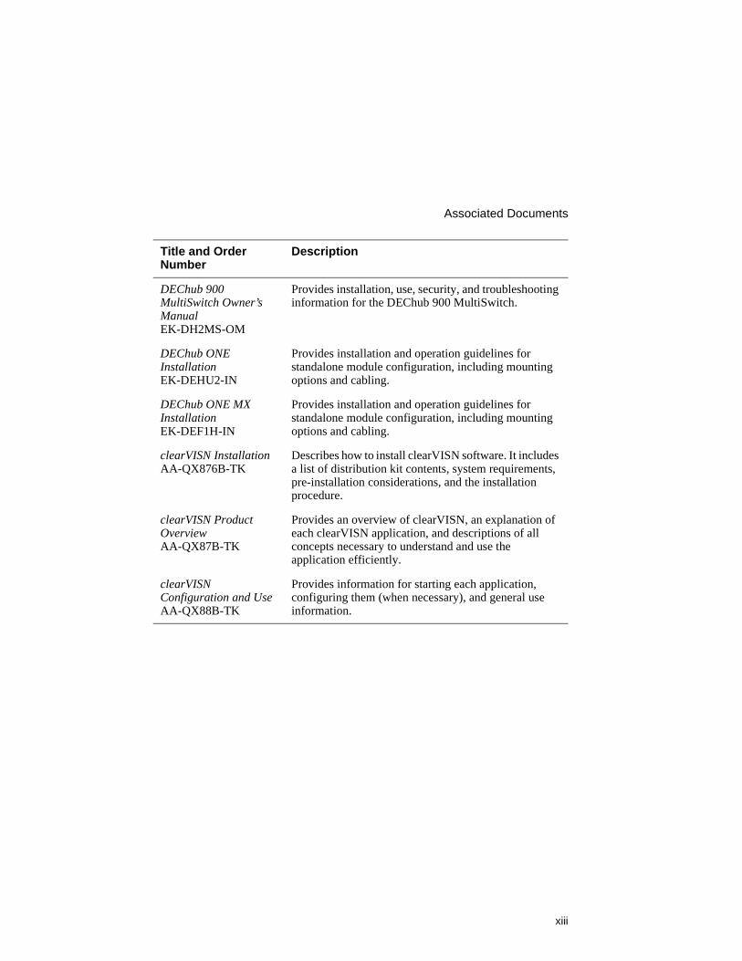
The following documents provide information relating to the module. To order any of the following documents, refer to the directions at the end of this preface.
Title and Order Number
Description
Bridging Configuration Guide AA-QL29D-TE
Describes bridging methods, operational features of bridging, configuration methods and basic configurations, and monitoring of bridging software.
Event Logging System Messages Guide AA-QL2AD-TE
Describes messages logged by the Event Logging System.
Network Interface Operations Guide AA-QL2BD-TE
Describes the configuring and monitoring of the network interfaces in the Bridge Router Software bridging router.
Bridge Router Software Router Protocols Reference Guide AA-QL2CD-TE
Provides detailed reference information about the micro-operating system structure and the protocols and interfaces that the bridging routers support.
Bridge Router Software Routing Protocols Users Guide AA-QL2DD-TE
Explains how to configure and monitor the routing protocol software.
Bridge Router Software System Software Guide AA-QL2ED-TE
Describes the installation, configuration, and operation of the Bridge Router Software.
Bridging Configuration Guide AA-QL29D-TE
Describes bridging methods, operational features of bridging, configuration methods and basic configurations, and monitoring of bridging software.
SNA Configuration Guide AA-QU5SB-TE
Describes SNA configuration.
xiii
Associated Documents
DEChub 900 MultiSwitch Owner’s Manual EK-DH2MS-OM
Provides installation, use, security, and troubleshooting information for the DEChub 900 MultiSwitch.
DEChub ONE Installation EK-DEHU2-IN
Provides installation and operation guidelines for standalone module configuration, including mounting options and cabling.
DEChub ONE MX Installation EK-DEF1H-IN
Provides installation and operation guidelines for standalone module configuration, including mounting options and cabling.
clearVISN Installation AA-QX876B-TK
Describes how to install clearVISN software. It includes a list of distribution kit contents, system requirements, pre-installation considerations, and the installation procedure.
clearVISN Product Overview AA-QX87B-TK
Provides an overview of clearVISN, an explanation of each clearVISN application, and descriptions of all concepts necessary to understand and use the application efficiently.
clearVISN Configuration and Use AA-QX88B-TK
Provides information for starting each application, configuring them (when necessary), and general use information.
Title and Order Number
Description
Correspondence
xiv
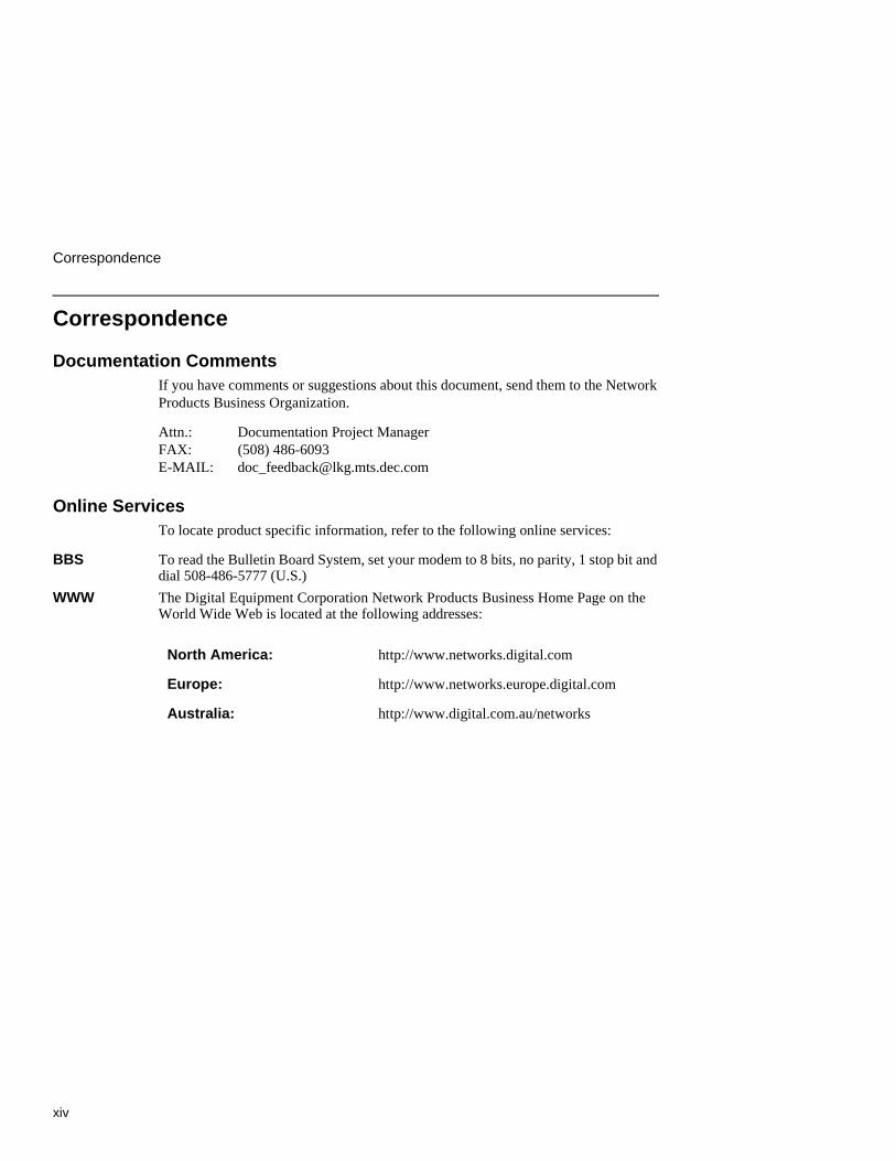
Correspondence
Documentation CommentsIf you have comments or suggestions about this document, send them to the Network Products Business Organization.
Attn.: Documentation Project ManagerFAX: (508) 486-6093E-MAIL: [email protected]
Online ServicesTo locate product specific information, refer to the following online services:
BBS To read the Bulletin Board System, set your modem to 8 bits, no parity, 1 stop bit and dial 508-486-5777 (U.S.)
WWW The Digital Equipment Corporation Network Products Business Home Page on the World Wide Web is located at the following addresses:
North America: http://www.networks.digital.com
Europe: http://www.networks.europe.digital.com
Australia: http://www.digital.com.au/networks
xv
How to Order Additional Documentation
How to Order Additional Documentation
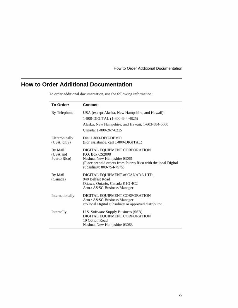
To order additional documentation, use the following information:
To Order: Contact:
By Telephone USA (except Alaska, New Hampshire, and Hawaii):
1-800-DIGITAL (1-800-344-4825)
Alaska, New Hampshire, and Hawaii: 1-603-884-6660
Canada: 1-800-267-6215
Electronically(USA. only)
Dial 1-800-DEC-DEMO(For assistance, call 1-800-DIGITAL)
By Mail (USA and Puerto Rico)
DIGITAL EQUIPMENT CORPORATIONP.O. Box CS2008Nashua, New Hampshire 03061(Place prepaid orders from Puerto Rico with the local Digital subsidiary: 809-754-7575)
By Mail (Canada)
DIGITAL EQUIPMENT of CANADA LTD.940 Belfast RoadOttawa, Ontario, Canada K1G 4C2Attn.: A&SG Business Manager
Internationally DIGITAL EQUIPMENT CORPORATIONAttn.: A&SG Business Managerc/o local Digital subsidiary or approved distributor
Internally U.S. Software Supply Business (SSB)DIGITAL EQUIPMENT CORPORATION10 Cotton RoadNashua, New Hampshire 03063


xvii
Safety
Overview
Any warning or caution that appears in this manual is defined as follows:.
WARNING Contains information to prevent personal injury.
CAUTION Contains information to prevent damage to equipment.
VORSICHT Enthält Informationen, die beachtet werden müssen um den Benutzer vor Schaden zu bewahren.
ACHTUNG Enthält Informationen, die beachtet werden müssen um die Gerate vor Schaden zu bewahren
DANGER Signale les informations destinées à prévenir les accidents corporels.
ATTENTION Signale les informations destinées à prévenir la détérioration du matériel.
AVISO Contiene información para evitar daños personales.
PRECAUCIÓN Contiene información para evitar daños al equipo.
xviii
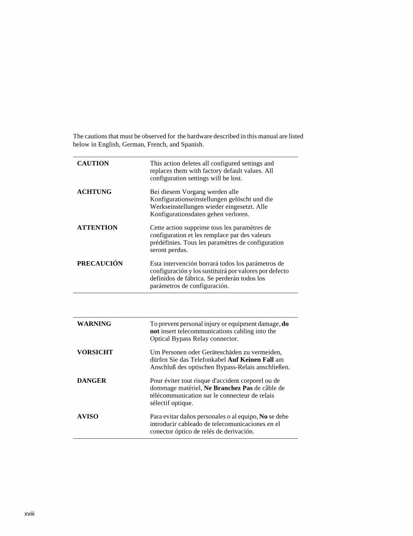
The cautions that must be observed for the hardware described in this manual are listed below in English, German, French, and Spanish.
CAUTION This action deletes all configured settings and replaces them with factory default values. All configuration settings will be lost.
ACHTUNG Bei diesem Vorgang werden alle Konfigurationseinstellungen gelöscht und die Werkseinstellungen wieder eingesetzt. Alle Konfigurationsdaten gehen verloren.
ATTENTION Cette action supprime tous les paramètres de configuration et les remplace par des valeurs prédéfinies. Tous les paramètres de configuration seront perdus.
PRECAUCIÓN Esta intervención borrará todos los parámetros de configuración y los sustituirá por valores por defecto definidos de fábrica. Se perderán todos los parámetros de configuración.
WARNING To prevent personal injury or equipment damage, do not insert telecommunications cabling into the Optical Bypass Relay connector.
VORSICHT Um Personen oder Geräteschäden zu vermeiden, dürfen Sie das Telefonkabel Auf Keinen Fall am Anschluß des optischen Bypass-Relais anschließen.
DANGER Pour éviter tout risque d'accident corporel ou de dommage matériel, Ne Branchez Pas de câble de télécommunication sur le connecteur de relais sélectif optique.
AVISO Para evitar daños personales o al equipo, No se debe introducir cableado de telecomunicaciones en el conector óptico de relés de derivación.

Product Description 1-1
Chapter 1
Product Description
Overview
IntroductionThis chapter describes the DECswitch 900EF Router product and its features.
In this chapter
Topic Page
What is the DECswitch 900EF Router? 1-2
Features 1-3

What is the DECswitch 900EF Router?
1-2 Product Description
What is the DECswitch 900EF Router?
The DECswitch 900EF Router (also referred to in this manual as the module) provides multiprotocol routing and switching. This module interconnects networks that have both routable and nonroutable protocols. It routes some protocols while switching others.
The module can be configured in the DEChub 900 MultiSwitch or as a standalone unit into a DEChub ONE or DEChub ONE-MX docking station (see the DEChub ONE Installation manual or the DEChub ONE-MX Installation manual).
The DECswitch 900EF Router is available with the following two protocol packages:
• Internet Protocol (IP)
• Multiprotocol (MP)
The IP package supports IP routing and bridging.The Multiprotocol package includes bridging and supports IP, IPX, AppleTalk Phases I & II, DECnet Phase IV, and DECnet/OSI protocols.
The DECswitch 900EF Router also provides virtual LAN support, in which the DECswitch bridges a protocol within a port group while concurrently routing the protocol between port groups. A port group is a set of switch ports and has a virtual interface that acts as a single connection on the LAN.
The DECswitch 900EF Router provides the interconnection between six 10 Mb/s Ethernet LANs and a high-speed 100 Mb/s Fiber Distributed Data Interface (FDDI) network backbone.
Ethernet is Digital’s term for its product compatibility with the ISO 8802-3/ANSI/IEEE 802.3 standards and the Ethernet standards for Carrier Sense Multiple Access with Collision Detection (CSMA/CD) local area networks (LANs).
The DECswitch 900EF Router standards-compliant technology (IEEE 802.1d, 802.1h, 802.1i, 802.2, 802.3, and ANSI FDDI) ensures interoperability in multivendor networks.
Product Description 1-3
Features
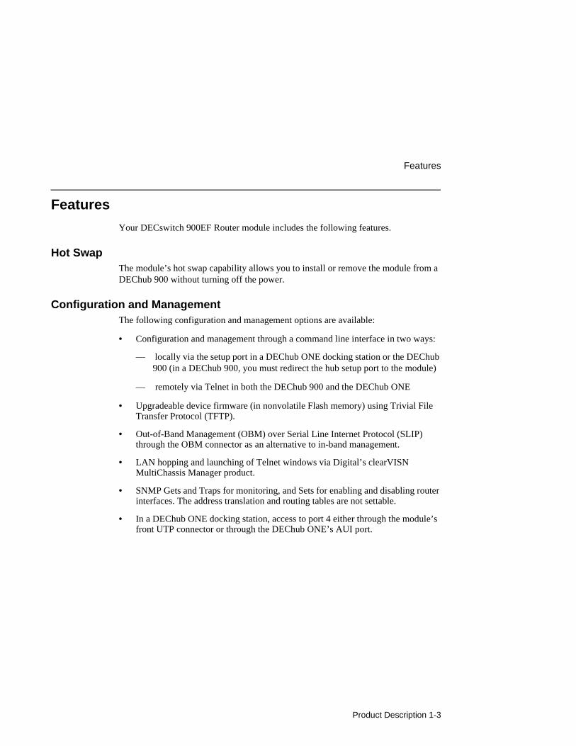
Features
Your DECswitch 900EF Router module includes the following features.
Hot SwapThe module’s hot swap capability allows you to install or remove the module from a DEChub 900 without turning off the power.
Configuration and ManagementThe following configuration and management options are available:
• Configuration and management through a command line interface in two ways:
— locally via the setup port in a DEChub ONE docking station or the DEChub 900 (in a DEChub 900, you must redirect the hub setup port to the module)
— remotely via Telnet in both the DEChub 900 and the DEChub ONE
• Upgradeable device firmware (in nonvolatile Flash memory) using Trivial File Transfer Protocol (TFTP).
• Out-of-Band Management (OBM) over Serial Line Internet Protocol (SLIP) through the OBM connector as an alternative to in-band management.
• LAN hopping and launching of Telnet windows via Digital’s clearVISN MultiChassis Manager product.
• SNMP Gets and Traps for monitoring, and Sets for enabling and disabling router interfaces. The address translation and routing tables are not settable.
• In a DEChub ONE docking station, access to port 4 either through the module’s front UTP connector or through the DEChub ONE’s AUI port.
Features
1-4 Product Description
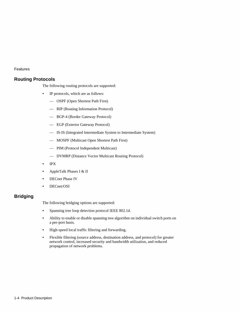
Routing ProtocolsThe following routing protocols are supported:
• IP protocols, which are as follows:
–– OSPF (Open Shortest Path First)
–– RIP (Routing Information Protocol)
–– BGP-4 (Border Gateway Protocol)
–– EGP (Exterior Gateway Protocol)
–– IS-IS (Integrated Intermediate System to Intermediate System)
–– MOSPF (Multicast Open Shortest Path First)
–– PIM (Protocol Independent Multicast)
–– DVMRP (Distance Vector Multicast Routing Protocol)
• IPX
• AppleTalk Phases I & II
• DECnet Phase IV
• DECnet/OSI
BridgingThe following bridging options are supported:
• Spanning tree loop detection protocol IEEE 802.1d.
• Ability to enable or disable spanning tree algorithm on individual switch ports on a per-port basis.
• High-speed local traffic filtering and forwarding.
• Flexible filtering (source address, destination address, and protocol) for greater network control, increased security and bandwidth utilization, and reduced propagation of network problems.
Product Description 1-5
Features
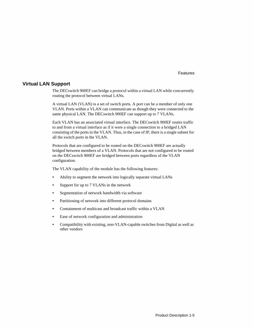
Virtual LAN SupportThe DECswitch 900EF can bridge a protocol within a virtual LAN while concurrently routing the protocol between virtual LANs.
A virtual LAN (VLAN) is a set of switch ports. A port can be a member of only one VLAN. Ports within a VLAN can communicate as though they were connected to the same physical LAN. The DECswitch 900EF can support up to 7 VLANs.
Each VLAN has an associated virtual interface. The DECswitch 900EF routes traffic to and from a virtual interface as if it were a single connection to a bridged LAN consisting of the ports in the VLAN. Thus, in the case of IP, there is a single subnet for all the switch ports in the VLAN.
Protocols that are configured to be routed on the DECswitch 900EF are actually bridged between members of a VLAN. Protocols that are not configured to be routed on the DECswitch 900EF are bridged between ports regardless of the VLAN configuration.
The VLAN capability of the module has the following features:
• Ability to segment the network into logically separate virtual LANs
• Support for up to 7 VLANs in the network
• Segmentation of network bandwidth via software
• Partitioning of network into different protocol domains
• Containment of multicast and broadcast traffic within a VLAN
• Ease of network configuration and administration
• Compatibility with existing, non-VLAN-capable switches from Digital as well as other vendors

Features
1-6 Product Description
SNMPThe complete MIB-II is provided with the exception of ifInNUcastPkts, ifOutNUcastPkts, and the TCP group. SNMP Gets and Traps are supported for the following RFCs.
• Structure and Identification of Management Information for TCP/IP-based Internets (RFC 1155)
• SNMP management (RFC 1157)
• Management Information Base for Network Management of TCP/IP-Based Internets: MIB-II (RFC 1213)
• AppleTalk MIB (RFC 1243)
• OSPF Version 2 MIB (RFC 1253)
• FDDI MIP (RFC 1285)
• Bridge MIB (RFC 1286)
• Ethernet MIB (RFC 1623)
Sets are supported for enabling and disabling router interfaces. The address translation and routing tables are not settable.
Manageability using any generic SNMP management application that supports the MIBs listed above.
Product Description 1-7
Features
FDDI/Ethernet FDDI and Ethernet support is as follows:
• One FDDI dual attachment station (DAS) port and six 802.3/Ethernet LAN ports.
• Translation between FDDI and IEEE 802.3/Ethernet frame formats for direct, transparent connections; translation of AppleTalk 1 and AppleTalk 2 AARP packets; handling of raw IEEE 802.3 Novell IPX packets.
• Console support for enabling and disabling translation of IPX raw 802.3 packets into SNAP encapsulated packets on the FDDI.
• Ability to switch FDDI port A to emulate a concentrator port M. If this is done, FDDI port B is automatically switched to emulate an S port.
• Each of the ports (including FDDI PHY ports 1A/M and 1B/S) is individually switchable to a DEChub 900 backplane LAN through the clearVISN MultiChassis Manager. Port 3 can be redirected to the DEChub 900 backplane ThinWire LAN segment via the clearVISN MultiChassis Manager.
EasyStartEasyStart is a feature that allows you to downline load configuration files that are stored on a central server. The configuration files are identified by the MAC address of a LAN interface on the router.
Using EasyStart eliminates the need for an initial configuration via the console port. When the module is booted, it autoconfigures all interfaces and sends out requests to load its configuration file. Once the file is received, the module automatically restarts so that the configuration parameters specified in the file take effect.

Installing the Module 2-1
Chapter 2
Installing the Module
Overview
IntroductionThis chapter describes the front and back panel components of the DECswitch 900EF Router and tells you how to install the DECswitch 900EF Router in a DEChub 900 MultiSwitch. To install a module in a DEChub ONE docking station refer to the DEChub ONE Installation manual.
In this chapter
Topic Page
Module Components 2-2
Installing the Module in a DEChub 900 2-8
Task 1: Compare the Power Ratings 2-9
Task 2: Seat the Module into the DEChub 900 2-10
Task 3: Verify Initial LED Operation 2-11
Task 4: Connect the Cables 2-12
Module Components
2-2 Installing the Module
Module Components
The following sections describe the front and back panel components for the DECswitch 900EF Router.
Table 2-1 describes the front panel components, including LEDs, that are illustrated in Figure 2-1.
Table 2-2 describes the back panel components as illustrated in Figure 2-2. For problem-solving information using the LEDs, refer to Appendix A.
Installing the Module 2-3
Front Panel Features
Front Panel Features
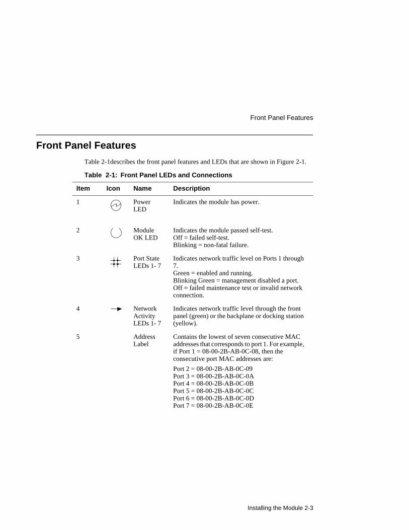
Table 2-1describes the front panel features and LEDs that are shown in Figure 2-1.
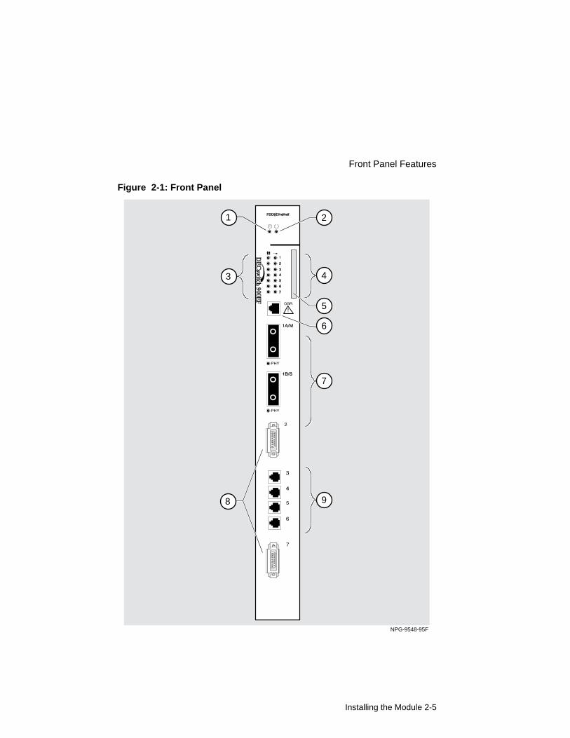
Table 2-1: Front Panel LEDs and Connections
Item Icon Name Description
1 Power LED
Indicates the module has power.
2 Module OK LED
Indicates the module passed self-test. Off = failed self-test. Blinking = non-fatal failure.
3 Port State LEDs 1- 7
Indicates network traffic level on Ports 1 through 7. Green = enabled and running.Blinking Green = management disabled a port. Off = failed maintenance test or invalid network connection.
4 Network Activity LEDs 1- 7
Indicates network traffic level through the front panel (green) or the backplane or docking station (yellow).
5 Address Label
Contains the lowest of seven consecutive MAC addresses that corresponds to port 1. For example, if Port 1 = 08-00-2B-AB-0C-08, then the consecutive port MAC addresses are:
Port 2 = 08-00-2B-AB-0C-09Port 3 = 08-00-2B-AB-0C-0APort 4 = 08-00-2B-AB-0C-0BPort 5 = 08-00-2B-AB-0C-0CPort 6 = 08-00-2B-AB-0C-0DPort 7 = 08-00-2B-AB-0C-0E

Front Panel Features
2-4 Installing the Module
6 OBR (6-pin MJ) connector
Allows you to connect an Optical Bypass Relay (OBR) device (not supplied) to maintain connectivity of the FDDI ring in the absence of power or during fault conditions in a station.
WARNING
To prevent personal injury or equipment damage, do not insert telecommunications cables into the Optical Bypass Relay connector.
7 DAS FDDI port connectors and their PHY LEDs
Indicates one Dual Attachment Station (DAS) port is labeled 1A/M and the other port is labeled 1B/S. Both ports are standard FDDI MIC connectors.
8 802.3/Ethernet AUI (15-pin D-Sub)
Refer to the OPEN DECconnect Applications Guide for a list of AUI media adapters you can use with your module.
9 10BaseT (8-pin MJ) connector
Wired as straight-through connectors; support UTP and STP cabling.
Item Icon Name Description
Installing the Module 2-5
Front Panel Features
Figure 2-1: Front Panel
NPG-9548-95F
5
9
4
6
7
1
3
8
2
Front Panel Features
2-6 Installing the Module
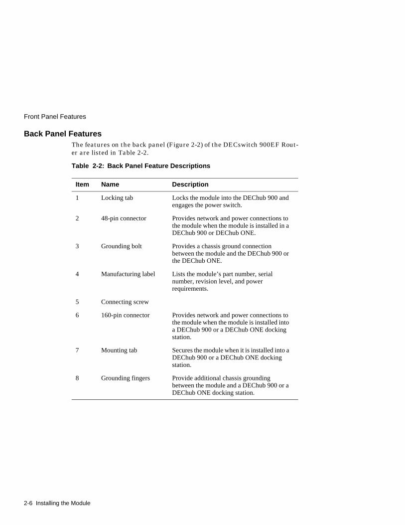
Back Panel FeaturesThe features on the back panel (Figure 2-2) of the DECswitch 900EF Rout-er are listed in Table 2-2.
Table 2-2: Back Panel Feature Descriptions
Item Name Description
1 Locking tab Locks the module into the DEChub 900 and engages the power switch.
2 48-pin connector Provides network and power connections to the module when the module is installed in a DEChub 900 or DEChub ONE.
3 Grounding bolt Provides a chassis ground connection between the module and the DEChub 900 or the DEChub ONE.
4 Manufacturing label Lists the module’s part number, serial number, revision level, and power requirements.
5 Connecting screw
6 160-pin connector Provides network and power connections to the module when the module is installed into a DEChub 900 or a DEChub ONE docking station.
7 Mounting tab Secures the module when it is installed into a DEChub 900 or a DEChub ONE docking station.
8 Grounding fingers Provide additional chassis grounding between the module and a DEChub 900 or a DEChub ONE docking station.
Installing the Module 2-7
Front Panel Features
Figure 2-2: Back Panel Layout
NPG-9723-95F
1
2
3
4
5
6
7
8

Installing the Module in a DEChub 900
2-8 Installing the Module
Installing the Module in a DEChub 900
The DECswitch 900EF Router hot-swap feature allows you to install the module into the DEChub 900 without turning off power. Seating the module initiates the module’s powerup sequence if enough power is available.
Installing the module in a DEChub 900 involves the following tasks:
Description Page
Task 1: Compare the Power Ratings 2-9
Task 2: Seat the Module into the DEChub 900 2-10
Task 3: Verify Initial LED Operation 2-11
Task 4: Connect the Cables 2-12

Installing the Module 2-9
Task 1: Compare the Power Ratings
Task 1: Compare the Power Ratings
Compare the module’s power ratings (1) with the values shown in the Hub Manager Status display (2) (see Figure 2-3). If the power values on the module’s manufacturing label do not exceed the values shown in the Hub Manager status display, go to Task 2.
If the power values on the module’s manufacturing label exceed the values shown in the Hub Manager status display, add another power supply to the DEChub 900 (refer to the DEChub 900 MultiSwitch Owner’s Manual.). The 12V power in the DEChub 900 is derived from the 15V source. Although it is listed separately in the product specifications, the 12V requirements are included in the 15V power total.
Figure 2-3: Module Power Ratings
9.0 A
0.1 A
1.5 A
5 V
12 V
15 V
67.5 W
1 2
NPG-0107-95F
Available: 90.5 W5V: 13.0 A, 15V: 3.5 A
Task 2: Seat the Module into the DEChub 900
2-10 Installing the Module
Task 2: Seat the Module into the DEChub 900
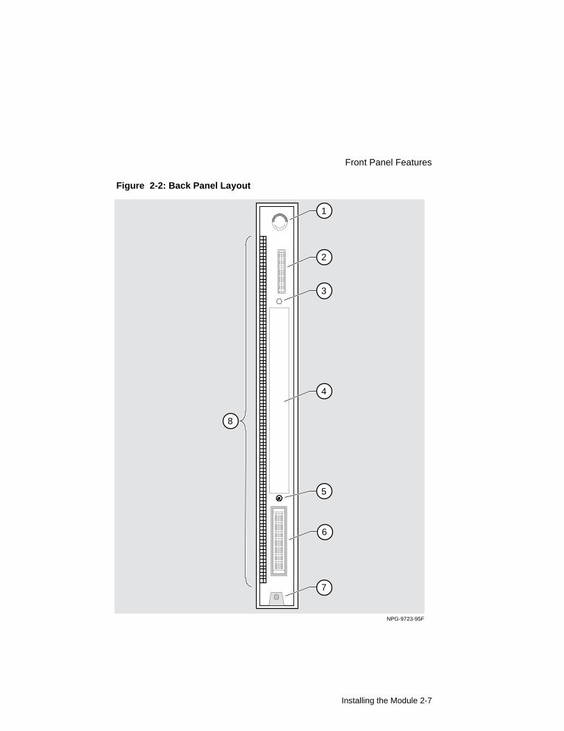
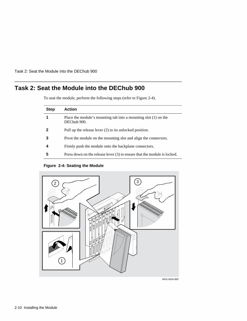
To seat the module, perform the following steps (refer to Figure 2-4).
Figure 2-4: Seating the Module
Step Action
1 Place the module’s mounting tab into a mounting slot (1) on the DEChub 900.
2 Pull up the release lever (2) to its unlocked position.
3 Pivot the module on the mounting slot and align the connectors.
4 Firmly push the module onto the backplane connectors.
5 Press down on the release lever (3) to ensure that the module is locked.
NPG-0004-95F
1
2 3
Installing the Module 2-11
Task 3: Verify Initial LED Operation
Task 3: Verify Initial LED Operation
Verify that the module’s Power LED and the Module OK LED light within 1 minute (see Figure 2-1). The LEDs light in the following two occurrences:
NOTE
Refer to Appendix A, Problem Solving if the LEDs do not operate as described.
Occurrence Description
1 The Power LED lights when power is applied to the DEChub 900, then the module performs a self-test.
2 After the module completes self-test, the Module OK LED lights and remains lit. Then the Hub Manager status display shows:
Slot <slot-number> DECswitch 900EF up.

Task 4: Connect the Cables
2-12 Installing the Module
Task 4: Connect the Cables
Depending on your network configuration requirements, connect the appropriate FDDI cables, AUI cables, and UTP/STP cables.
See your network manager if you are not sure which cables to connect.
NOTE
All cables should be installed, tested, and tagged at the site, prior to this installation.
After all cables are installed, go to Chapter 5, Configuring the Module in a DEChub 900.
To Go to
Connect FDDI cables 2-13
Connect AUI cables 2-14
Connect UTP/STP cables 2-15
Connect Optical Bypass Relay (OBR) The installation instructions included with the OBR

Installing the Module 2-13
Task 4: Connect the Cables
Task 4 (Cont.): Connect the FDDI CableTo connect the FDDI cable, complete the following steps (see Figure 2-5).
NOTE
To disconnect the cables, press the locking clips on the cable plug (1), then pull out the connector.
Figure 2-5: FDDI Cable Connection
Step Action
1 Remove the protective caps from the module’s FDDI connector and from the FDDI cable plug.
2 Align the keyway on the FDDI cable plug with the key on the module’s FDDI connector.
3 Insert the plug into the connector (2), ensuring that the locking clips (1) on the sides of the plug snap into the locked position.
NPG-0110-95F
1
2
Task 4: Connect the Cables
2-14 Installing the Module
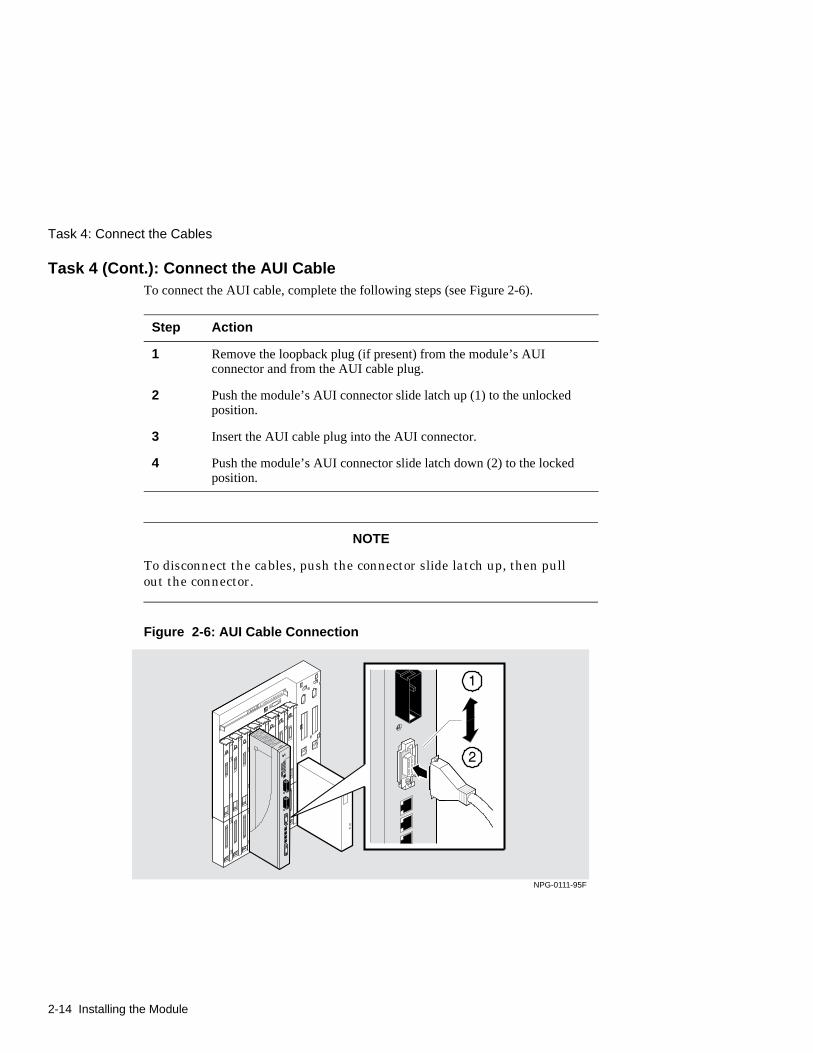
Task 4 (Cont.): Connect the AUI CableTo connect the AUI cable, complete the following steps (see Figure 2-6).
NOTE
To disconnect the cables, push the connector slide latch up, then pull out the connector.
Figure 2-6: AUI Cable Connection
Step Action
1 Remove the loopback plug (if present) from the module’s AUI connector and from the AUI cable plug.
2 Push the module’s AUI connector slide latch up (1) to the unlocked position.
3 Insert the AUI cable plug into the AUI connector.
4 Push the module’s AUI connector slide latch down (2) to the locked position.
NPG-0111-95F

Installing the Module 2-15
Task 4: Connect the Cables
Task 4 (Cont.): Connecting the UTP/STP CableThe DECswitch 900EF Router module uses straight-through 10BaseT (8-pin MJ) port connectors. Select the appropriate UTP/STP cable type (crossover or straight-through) to ensure that the module’s transmit/receive signals connect correctly to the transmitter/receiver of the connected device.
Before connecting the cables to the module, note the following rules:
NOTES
Digital’s straight-through cables are marked (=); crossover connectors (and cables) are marked (X).
If you need help determining the appropriate cable type to use, refer to Appendix B, Connector and Pin Assignments.
If the device you are connecting the module to is a
Then use
DTE (data terminal equipment) device Crossover cables
DCE (data circuit-terminating equipment) device Straight-through cables
Task 4: Connect the Cables
2-16 Installing the Module
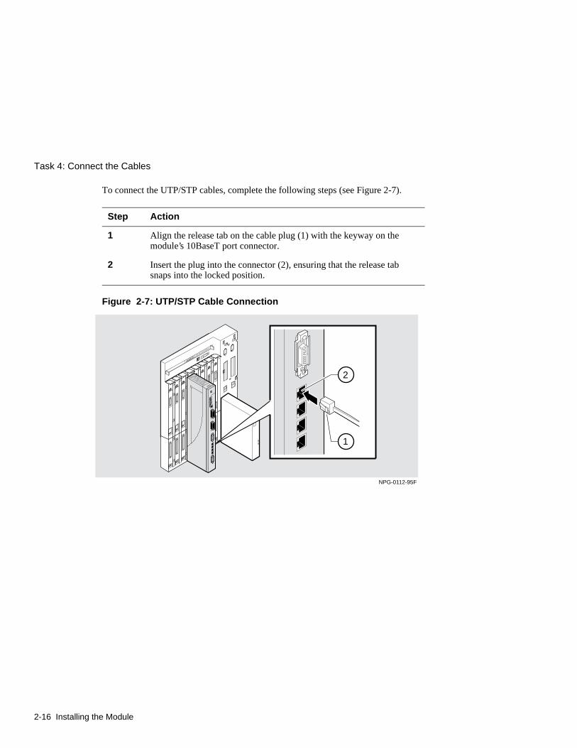
To connect the UTP/STP cables, complete the following steps (see Figure 2-7).
Figure 2-7: UTP/STP Cable Connection
Step Action
1 Align the release tab on the cable plug (1) with the keyway on the module’s 10BaseT port connector.
2 Insert the plug into the connector (2), ensuring that the release tab snaps into the locked position.
NPG-0112-95F
1
2

Installing the Setup Port Cable 3-1
Chapter 3
Installing the Setup Port Cable
Overview
IntroductionThis chapter describes how to connect the DECswitch 900EF Router module to the setup port on a DEChub 900 MultiSwitch or a DEChub ONE docking station.
In this chapter
Topic Page
Signaling Standards 3-2
Setup Port Device Cabling 3-3
Connecting the Setup Port 3-4

Signaling Standards
3-2 Installing the Setup Port Cable
Signaling Standards
Signals from the DEChub 900 Hub setup port and from the DEChub ONE docking station setup port conform to the EIA-232D signaling standard at 9600 baud. To the user, the port appears as a data terminal equipment (DTE) device.
Installing the Setup Port Cable 3-3
Setup Port Device Cabling
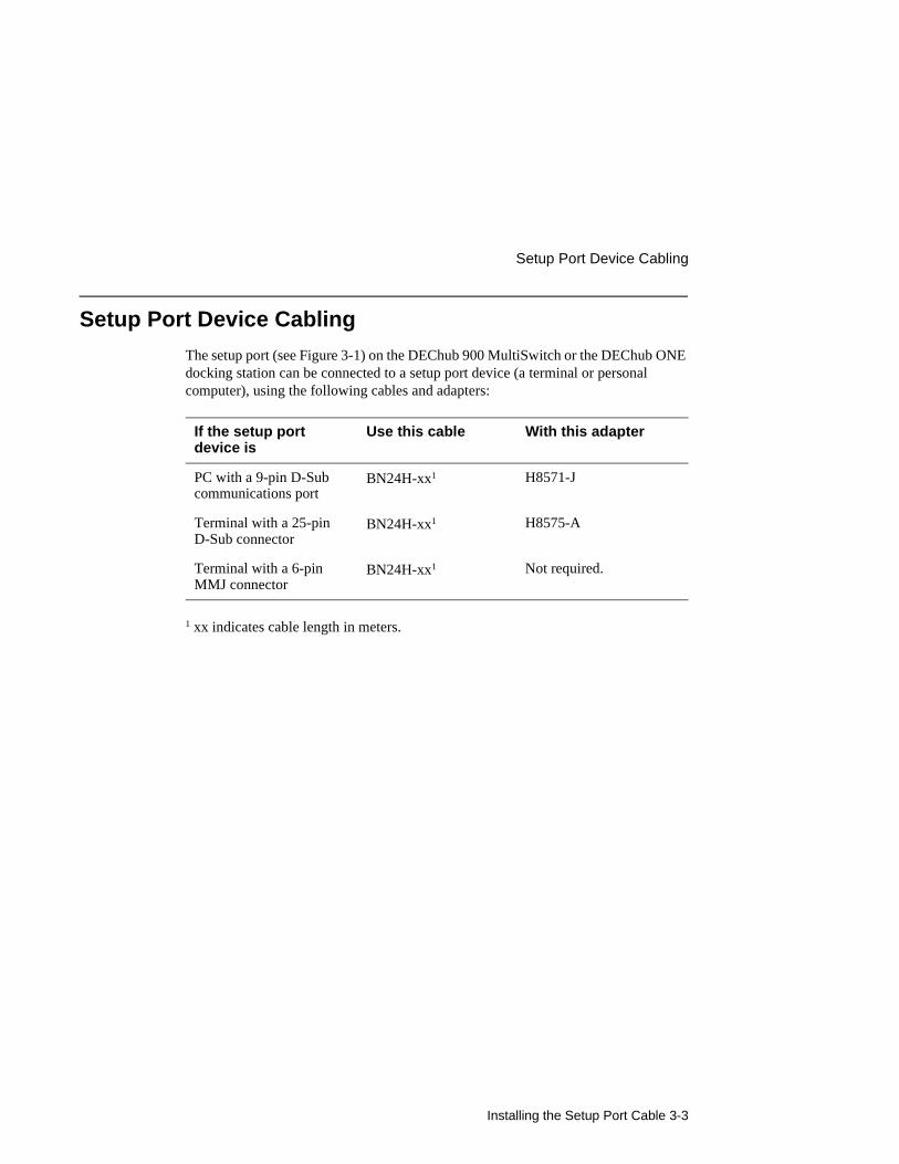
Setup Port Device Cabling
The setup port (see Figure 3-1) on the DEChub 900 MultiSwitch or the DEChub ONE docking station can be connected to a setup port device (a terminal or personal computer), using the following cables and adapters:
1 xx indicates cable length in meters.
If the setup port device is
Use this cable With this adapter
PC with a 9-pin D-Sub communications port
BN24H-xx1 H8571-J
Terminal with a 25-pin D-Sub connector
BN24H-xx1 H8575-A
Terminal with a 6-pin MMJ connector
BN24H-xx1 Not required.
Connecting the Setup Port
3-4 Installing the Setup Port Cable
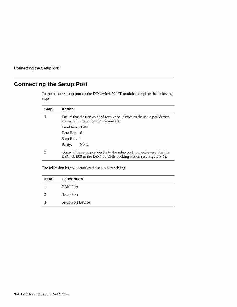
Connecting the Setup Port
To connect the setup port on the DECswitch 900EF module, complete the following steps:
The following legend identifies the setup port cabling.
Step Action
1 Ensure that the transmit and receive baud rates on the setup port device are set with the following parameters:
Baud Rate: 9600
Data Bits: 8
Stop Bits: 1
Parity: None
2 Connect the setup port device to the setup port connector on either the DEChub 900 or the DEChub ONE docking station (see Figure 3-1).
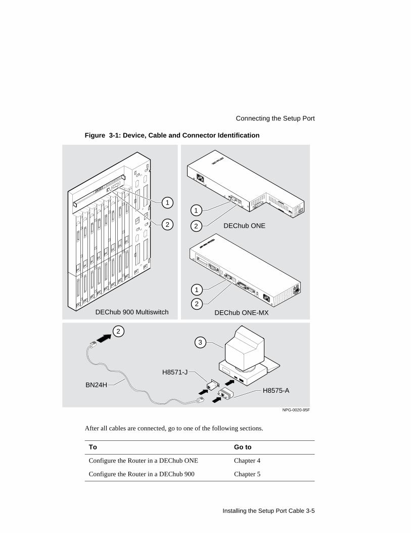
Item Description
1 OBM Port
2 Setup Port
3 Setup Port Device
Installing the Setup Port Cable 3-5
Connecting the Setup Port
Figure 3-1: Device, Cable and Connector Identification
After all cables are connected, go to one of the following sections.
To Go to
Configure the Router in a DEChub ONE Chapter 4
Configure the Router in a DEChub 900 Chapter 5
BN24H
H8571-J
H8575-A
1
2
2
3
NPG-0020-95F
DEChub 900 Multiswitch
DEChub ONE
1
2
DEChub ONE-MX
1
2

Configuring the Module in a Standalone Unit 4-1
Chapter 4
Configuring the Module in a Standalone Unit
Overview
IntroductionThis chapter describes how to setup and configure your DECswitch 900EF Router when it is installed as a standalone unit.
In this chapter
Topic Page
Accessing the Setup Port 4-2
Using Menus to Setup the Module 4-3
Accessing the Setup Port
4-2 Configuring the Module in a Standalone Unit
Accessing the Setup Port
To configure your module and make it remotely accessible you must assign:
• An IP address
• A subnet mask
• A default gateway
• An SNMP community string, if the module will be managed by the clearVISN MultiChassis Manager. See the clearVISN Product Overview for more information.
You can configure the module through either
• a Telnet session
or
• the console configuration interface which is accessed by connecting a terminal to the console port on the module.
The setup port provides menus that allow you to access the DECswitch 900EF Router. These menus allow you to setup the module for basic connectivity. After the initial setup, you can configure the module software using a command-based interface. These commands can be accessed remotely via Telnet, or accessed locally through the setup port on a DEChub ONE docking station.
Examples of the setup screen displays are provided in this section to aid in the description of the setup port and to display the options that are available. Because they are examples only, the displays can vary slightly from the actual screen displays on your setup port device. Boldface type in the screen display examples indicates user input.
To access the setup menus, press the Return key on the setup port device until the DECswitch 900EF/MP INSTALLATION MENU appears (see Chapter 3, Installing the Setup Port Cable for information about connecting the setup port device).
To configure the module using Go to the section titled
Menus Using Menus to Setup the Module
Commands Go To Local Console

Configuring the Module in a Standalone Unit 4-3
Using Menus to Setup the Module
Using Menus to Setup the Module
This section describes the options that are available from the DECswitch 900EF/MP INSTALLATION MENU when the module is installed in the DEChub ONE docking station.
When the module powers up, the EasyStart feature begins to run. See the Distributed Routing Software guides for more information. After the EasyStart feature has executed, the following menu appears if the module is setup with factory defaults, or if the module is configured for bridging and IP only.
NOTE
The /MP that appears in menus will be replaced with /IP when using the IP-only package.
DECswitch900EF/MP============================================================= DECswitch 900EF/MP INSTALLATION MENU
[1] Restart with Factory Defaults [2] Restart with Current Settings [3] Show Current Settings [4] Configure IP . . . [5] Configure Out-of-Band Port ... [6] Go to Local Console
============================================================= Enter selection:
Using Menus to Setup the Module
4-4 Configuring the Module in a Standalone Unit
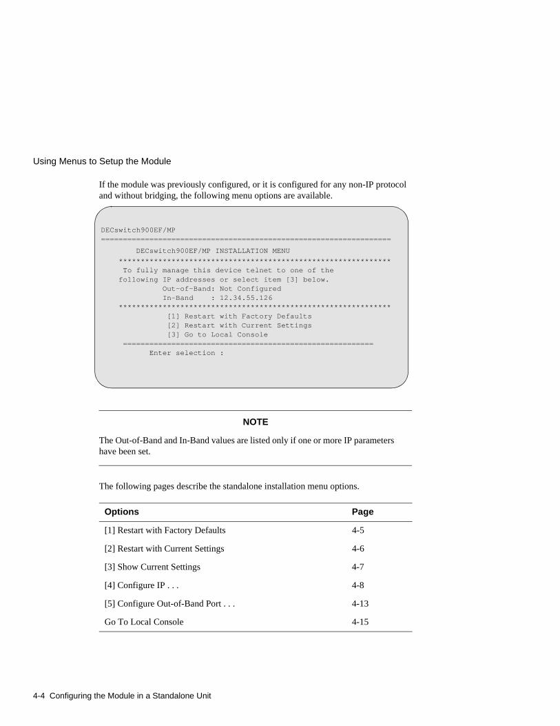
If the module was previously configured, or it is configured for any non-IP protocol and without bridging, the following menu options are available.
NOTE
The Out-of-Band and In-Band values are listed only if one or more IP parameters have been set.
The following pages describe the standalone installation menu options.
Options Page
[1] Restart with Factory Defaults 4-5
[2] Restart with Current Settings 4-6
[3] Show Current Settings 4-7
[4] Configure IP . . . 4-8
[5] Configure Out-of-Band Port . . . 4-13
Go To Local Console 4-15
DECswitch900EF/MP==================================================================
DECswitch900EF/MP INSTALLATION MENU ************************************************************** To fully manage this device telnet to one of the following IP addresses or select item [3] below. Out-of-Band: Not Configured In-Band : 12.34.55.126 ************************************************************** [1] Restart with Factory Defaults [2] Restart with Current Settings [3] Go to Local Console ========================================================= Enter selection :

Configuring the Module in a Standalone Unit 4-5
[1] Restart with Factory Defaults
[1] Restart with Factory Defaults
This option initializes the router configuration to factory default values by resetting the module’s nonvolatile configuration storage parameters and then restarting the module. (To retain current values, use Option [2] Restart with Current Settings). Allow approximately one minute for the module to restart and complete self-test.
CAUTION
This action deletes all configured settings and replaces them with factory default values. All configuration settings will be lost.
The following example shows the dialog associated with this option.
If you selected Y, then the following additional information appears:
Then, the EasyStart rebooting feature becomes active. The EasyStart feature allows the module to boot up using existing configuration files. EasyStart messages may appear on the console device. See the Distributed Routing Software guides for more information about the EasyStart feature.
The DECswitch 900EF/MP INSTALLATION MENU menu appears.
Enter selection : 1DECswitch900EF/MP================================================================= RESTART WITH FACTORY DEFAULTS * * * * * * * * * * * * * * * * * * * * * * * * * * * * * * * IMPORTANT! IMPORTANT! IMPORTANT! * * * * * * * * * * * * * * * * * * * * * * * * * * * * * * * * This selection will delete the current configuration * * settings and restart the system with the factory default* * settings. All configuration settings will be lost. * * * * * * * * * * * * * * * * * * * * * * * * * * * * * * *================================================================= Press Y to confirm [N]:
About to Initialize CONFIG memory Configuration memory initialized System Restart ...

[2] Restart with Current Settings
4-6 Configuring the Module in a Standalone Unit
[2] Restart with Current Settings
This option restarts the module but leaves the module’s configured nonvolatile configuration storage parameters at their current values. The module should restart in less than one minute.
The following example shows the dialog associated with this option.
If you select Y, then the DECswitch900EF/MP INSTALLATION MENU appears.
Enter selection: 2
DECswitch900EF/MP
=============================================================
RESTART WITH CURRENT SETTINGS
This selection will restart your system with the current
configuration settings.
=============================================================
Press Y to confirm [N] : <Return>
Press Return for Main Menu ...

Configuring the Module in a Standalone Unit 4-7
[3] Show Current Settings
[3] Show Current Settings
This option shows the module’s current settings. If the module is being configured for the first time, some of the fields will be blank.
The following example shows the dialog associated with this option.
Enter selection : 3
DECswitch900EF/MP
===================================================================
DECswitch900EF/MP,MP Brouter:6 Enet 1 FDDI,HW=v1/2,#1489,SW=v2.0.000
SysUpTime : 00:00:52 28 resets
SNMP Read/Write Community : whitney95
Out-of-Band (OBM) Management RTS : Disabled
Default Gateway : 16.126.16.254
------------------------------------------------------------------
Interface IP Address Subnet Mask Other Info
Ethernet 16.126.16.116 255.255.255.0
------------------------------------------------------------------
==================================================================
Press Return for Main Menu ...
[4] Configure IP . . .
4-8 Configuring the Module in a Standalone Unit
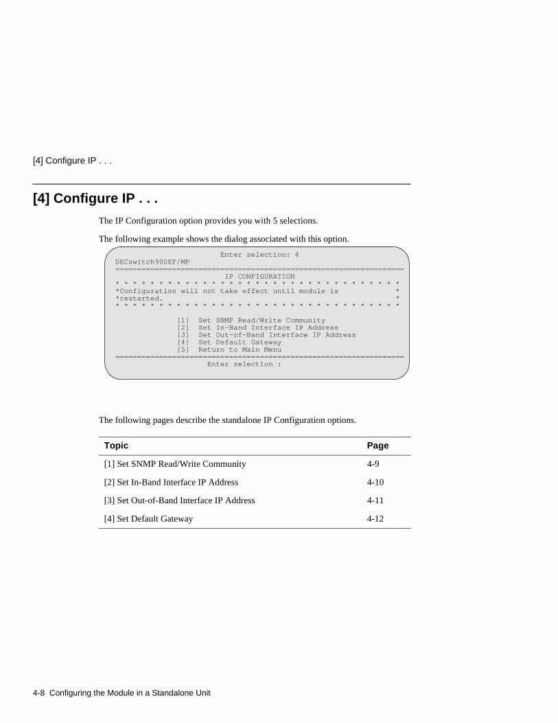
[4] Configure IP . . .
The IP Configuration option provides you with 5 selections.
The following example shows the dialog associated with this option.
The following pages describe the standalone IP Configuration options.
Topic Page
[1] Set SNMP Read/Write Community 4-9
[2] Set In-Band Interface IP Address 4-10
[3] Set Out-of-Band Interface IP Address 4-11
[4] Set Default Gateway 4-12
Enter selection: 4DECswitch900EF/MP================================================================== IP CONFIGURATION* * * * * * * * * * * * * * * * * * * * * * * * * * * * * * * * **Configuration will not take effect until module is **restarted. ** * * * * * * * * * * * * * * * * * * * * * * * * * * * * * * * *
[1] Set SNMP Read/Write Community [2] Set In-Band Interface IP Address [3] Set Out-of-Band Interface IP Address [4] Set Default Gateway [5] Return to Main Menu================================================================== Enter selection :
Configuring the Module in a Standalone Unit 4-9
[4] Configure IP . . .
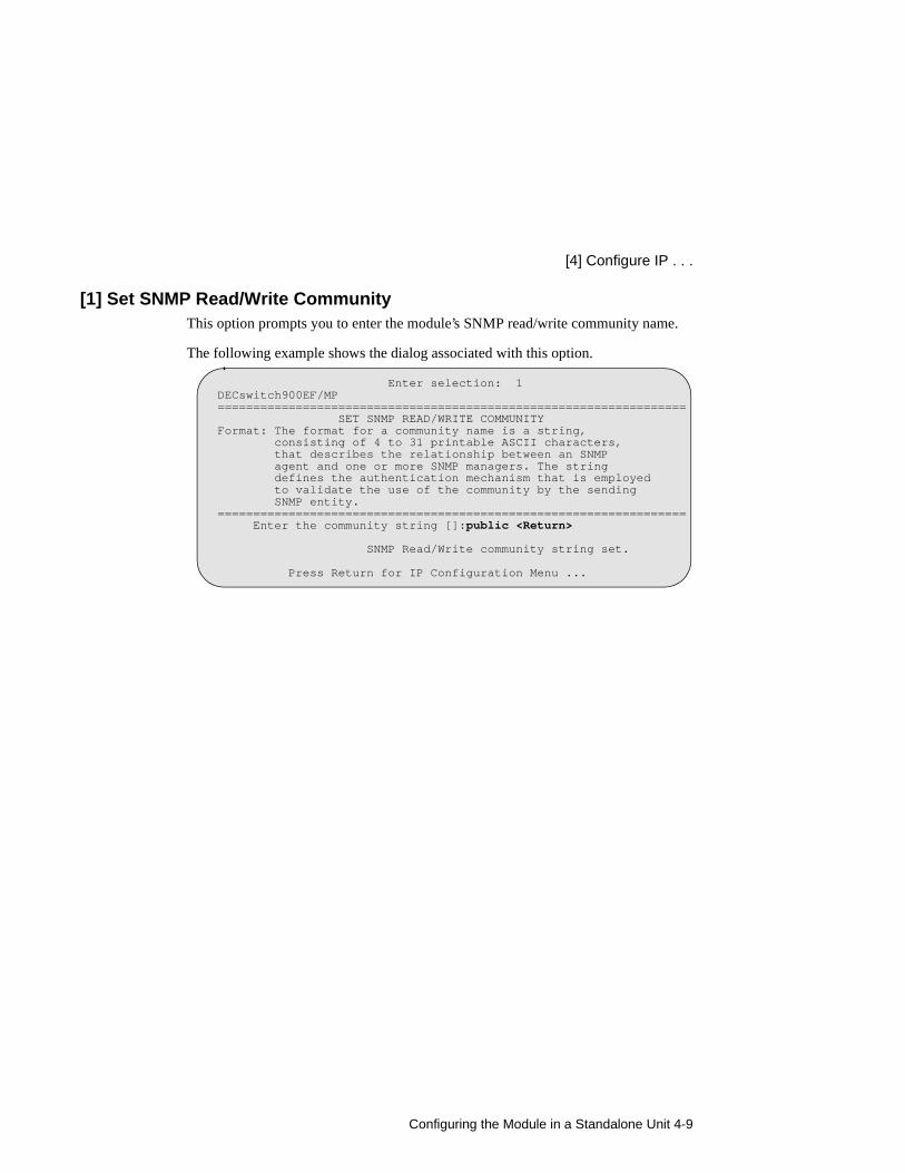
[1] Set SNMP Read/Write CommunityThis option prompts you to enter the module’s SNMP read/write community name.
The following example shows the dialog associated with this option.
Enter selection: 1DECswitch900EF/MP================================================================== SET SNMP READ/WRITE COMMUNITYFormat: The format for a community name is a string, consisting of 4 to 31 printable ASCII characters, that describes the relationship between an SNMP agent and one or more SNMP managers. The string defines the authentication mechanism that is employed to validate the use of the community by the sending SNMP entity.================================================================== Enter the community string []:public <Return>
SNMP Read/Write community string set.
Press Return for IP Configuration Menu ...

[4] Configure IP . . .
4-10 Configuring the Module in a Standalone Unit
[2] Set In-Band Interface IP AddressThis option prompts you to change or enter the IP address and subnet mask for the in-band interface. You can only configure one in-band interface at a time. The module does not need to be configured with a subnet mask for SNMP and Telnet communications with management stations located on the same subnet as the module.
The format for these values is the standard 4-octet dotted decimal notation, in which each octet of the address is represented as a decimal value, separated by a decimal point (.).
The following example shows the dialog associated with this option.
Enter selection: 2
DECswitch900EF/MP
==================================================================
IN-BAND INTERFACE IP ADDRESS CONFIGURATIONFormat: The standard 4 octet dotted decimal notation in which
each octet of the address is represented as a decimal
value, separated by a ’.’ character.
example: 16.20.40.156
To delete the address, enter 0 in the appropriate address
field.
-------------------------------------------------------------------
Interface IP Address Subnet Mask Other Info
Ethernet
-------------------------------------------------------------------
==================================================================
Port Number (1-7) [ ]: 2
Enter the IP address [ ]: 16.126.16.116 <Return>
Enter the Subnet Mask [255.0.0.0] : 255.255.255.0 <Return>
Press Return for IP Configuration Menu ...
Configuring the Module in a Standalone Unit 4-11
[4] Configure IP . . .
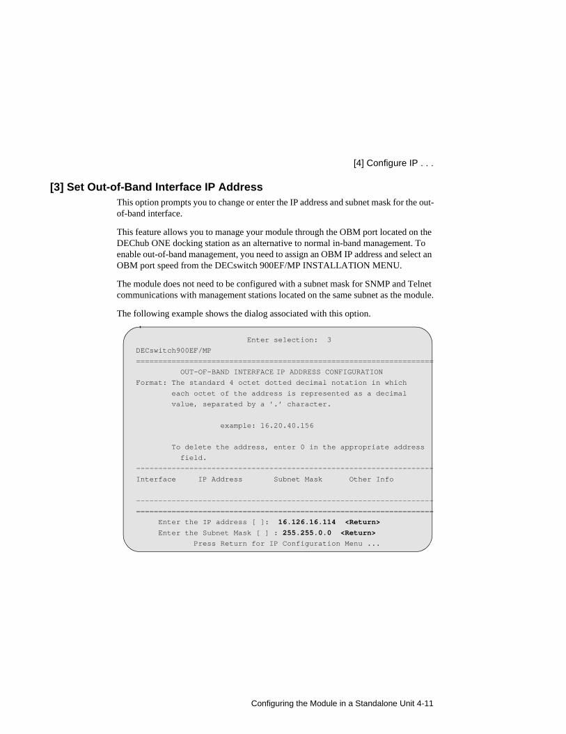
[3] Set Out-of-Band Interface IP AddressThis option prompts you to change or enter the IP address and subnet mask for the out-of-band interface.
This feature allows you to manage your module through the OBM port located on the DEChub ONE docking station as an alternative to normal in-band management. To enable out-of-band management, you need to assign an OBM IP address and select an OBM port speed from the DECswitch 900EF/MP INSTALLATION MENU.
The module does not need to be configured with a subnet mask for SNMP and Telnet communications with management stations located on the same subnet as the module.
The following example shows the dialog associated with this option.
Enter selection: 3
DECswitch900EF/MP
===================================================================
OUT-OF-BAND INTERFACE IP ADDRESS CONFIGURATIONFormat: The standard 4 octet dotted decimal notation in which
each octet of the address is represented as a decimal
value, separated by a ’.’ character.
example: 16.20.40.156
To delete the address, enter 0 in the appropriate address
field.
-------------------------------------------------------------------
Interface IP Address Subnet Mask Other Info
-------------------------------------------------------------------
===================================================================
Enter the IP address [ ]: 16.126.16.114 <Return>
Enter the Subnet Mask [ ] : 255.255.0.0 <Return>
Press Return for IP Configuration Menu ...
[4] Configure IP . . .
4-12 Configuring the Module in a Standalone Unit
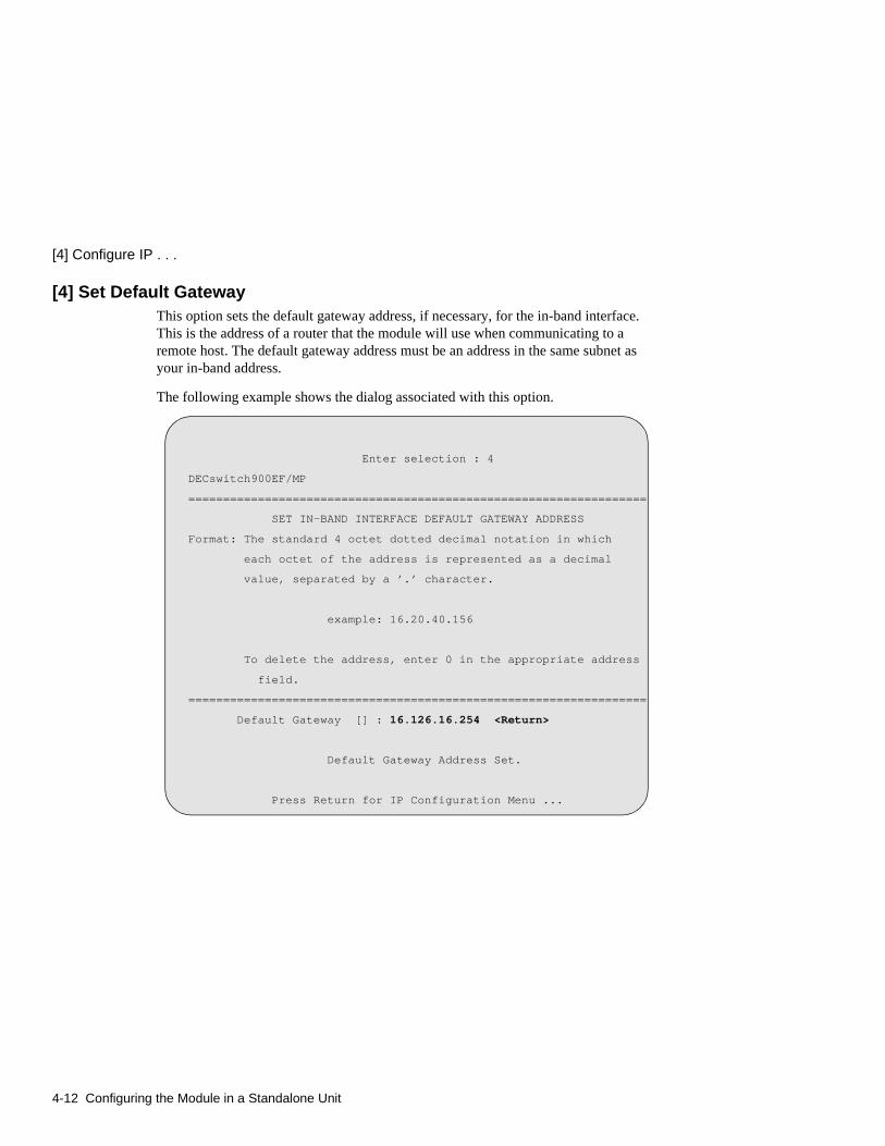
[4] Set Default GatewayThis option sets the default gateway address, if necessary, for the in-band interface. This is the address of a router that the module will use when communicating to a remote host. The default gateway address must be an address in the same subnet as your in-band address.
The following example shows the dialog associated with this option.
Enter selection : 4
DECswitch900EF/MP
==================================================================
SET IN-BAND INTERFACE DEFAULT GATEWAY ADDRESS
Format: The standard 4 octet dotted decimal notation in which
each octet of the address is represented as a decimal
value, separated by a ’.’ character.
example: 16.20.40.156
To delete the address, enter 0 in the appropriate address
field.
==================================================================
Default Gateway [] : 16.126.16.254 <Return>
Default Gateway Address Set.
Press Return for IP Configuration Menu ...
Configuring the Module in a Standalone Unit 4-13
[5] Configure Out-of-Band Port . . .
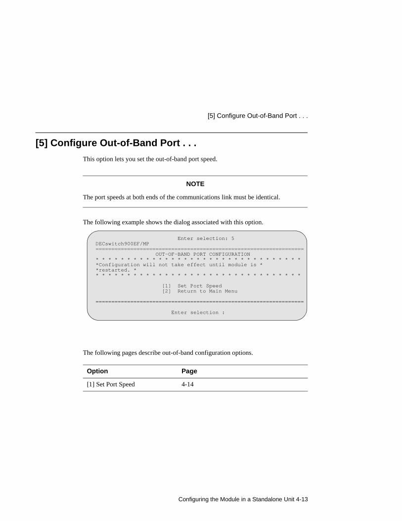
[5] Configure Out-of-Band Port . . .
This option lets you set the out-of-band port speed.
NOTE
The port speeds at both ends of the communications link must be identical.
The following example shows the dialog associated with this option.
The following pages describe out-of-band configuration options.
Option Page
[1] Set Port Speed 4-14
Enter selection: 5DECswitch900EF/MP================================================================== OUT-OF-BAND PORT CONFIGURATION* * * * * * * * * * * * * * * * * * * * * * * * * * * * * * * * **Configuration will not take effect until module is **restarted. ** * * * * * * * * * * * * * * * * * * * * * * * * * * * * * * * *
[1] Set Port Speed ==================================================================
Enter selection :
[2] Return to Main Menu

[5] Configure Out-of-Band Port . . .
4-14 Configuring the Module in a Standalone Unit
[1] Set Port SpeedThis option lets you select the out-of-band port speed. The factory default for this option is 9600 baud. The OBM port speed that you select must match the speed of your OBM device.
The following example shows the dialog associated with this option.
Enter selection: 1
DECswitch900EF/MP
==================================================================
SET OUT-OF-BAND MANAGEMENT INTERFACE PORT SPEED
[1] 2400 baud
[2] 9600 baud
[3] 38400 baud
==================================================================
Enter selection [2] (9600): 1 <Return>
OBM port speed set...
Press Return for Main Menu ...
Configuring the Module in a Standalone Unit 4-15
Go To Local Console
Go To Local Console
This option lets you configure the module.You must configure the module before it is operational. The Go to Local Console option provides two different configuration methods, depending on whether the module has been setup with factory defaults or has been previously configured.
If the module has been setup with factory defaults, or is configured for bridging and for IP-only operation, then this is option [6] Go to Local Console from the DECswitch900EF/MP INSTALLATION MENU. This option runs a quick configuration interactive question and answer dialog. This method (qconfig) allows fast configuration of interfaces, basic bridging, and IP configuration.
If the module has been previously configured, or is configured with a non-IP protocol and with no bridging, then this is option [3] Go to Local Console from the installation menu. This option allows you to configure the module using commands to configure interfaces, bridging, and routing protocol.
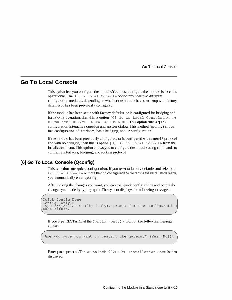
[6] Go To Local Console (Qconfig)This selection runs quick configuration. If you reset to factory defaults and select Go to Local Console without having configured the router via the installation menu, you automatically enter qconfig.
After making the changes you want, you can exit quick configuration and accept the changes you made by typing: quit. The system displays the following messages:
If you type RESTART at the Config (only)> prompt, the following message appears:
Enter yes to proceed.The DECswitch 900EF/MP Installation Menu is then displayed.
Quick Config DoneConfig (only)>Type RESTART at Config (only)> prompt for the configuration take effect.
Are you sure you want to restart the gateway? (Yes [No]):
Go To Local Console
4-16 Configuring the Module in a Standalone Unit
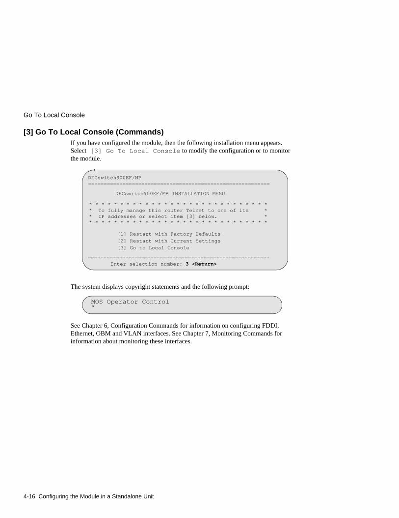
[3] Go To Local Console (Commands)If you have configured the module, then the following installation menu appears. Select [3] Go To Local Console to modify the configuration or to monitor the module.
The system displays copyright statements and the following prompt:
See Chapter 6, Configuration Commands for information on configuring FDDI, Ethernet, OBM and VLAN interfaces. See Chapter 7, Monitoring Commands for information about monitoring these interfaces.
DECswitch900EF/MP ==========================================================
DECswitch900EF/MP INSTALLATION MENU
* * * * * * * * * * * * * * * * * * * * * * * * * * * * * * To fully manage this router Telnet to one of its * * IP addresses or select item [3] below. * * * * * * * * * * * * * * * * * * * * * * * * * * * * * *
[1] Restart with Factory Defaults
[2] Restart with Current Settings[3] Go to Local Console
==========================================================
Enter selection number: 3 <Return>
MOS Operator Control*

Configuring the Module in a DEChub 900 5-1
Chapter 5
Configuring the Module in a DEChub 900
Overview
IntroductionThis chapter describes how to configure your DECswitch 900EF Router when it resides in a DEChub 900 MultiSwitch.
In this chapter
Topic Page
Accessing the Setup Port 5-2
DEChub 900 MultiSwitch Installation Menu 5-4
Using Menus to Setup the Module 5-6
Accessing the Setup Port
5-2 Configuring the Module in a DEChub 900
Accessing the Setup Port
The basic steps you must follow to configure your module and make it remotely accessible are to assign:
• An IP address
• A subnet mask
• A default gateway
• An SNMP community string, if the module will be managed by the clearVISN MultiChassis Manager. See the clearVISN Product Overview for more information.
You can configure the module through either
• a Telnet session
or
• the console configuration interface which is accessed by connecting a terminal to the console port on the hub, then redirecting to the module.
The setup port provides menus that allow you to access the DECswitch 900EF Router. These menus allow you to setup the module for basic connectivity. After the initial setup, you can configure the module software using a command-based interface. These commands can be accessed remotely via Telnet, or accessed locally through the setup port.
NOTE
You must restart the module in order for the configuration changes to take effect. The hub will close the connection to the selected slot after restart, but after the module has restarted, you can redirect to the desired slot and resume communication.
Configuring the Module in a DEChub 900 5-3
Accessing the Setup Port
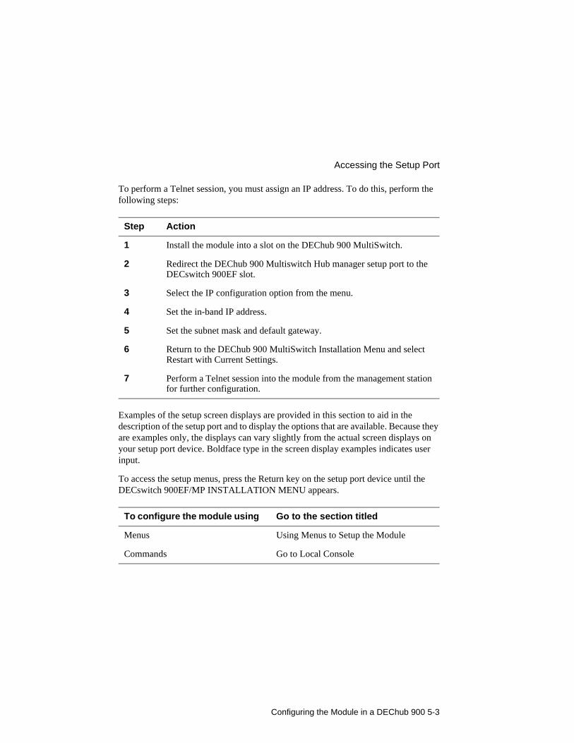
To perform a Telnet session, you must assign an IP address. To do this, perform the following steps:
Examples of the setup screen displays are provided in this section to aid in the description of the setup port and to display the options that are available. Because they are examples only, the displays can vary slightly from the actual screen displays on your setup port device. Boldface type in the screen display examples indicates user input.
To access the setup menus, press the Return key on the setup port device until the DECswitch 900EF/MP INSTALLATION MENU appears.
Step Action
1 Install the module into a slot on the DEChub 900 MultiSwitch.
2 Redirect the DEChub 900 Multiswitch Hub manager setup port to the DECswitch 900EF slot.
3 Select the IP configuration option from the menu.
4 Set the in-band IP address.
5 Set the subnet mask and default gateway.
6 Return to the DEChub 900 MultiSwitch Installation Menu and select Restart with Current Settings.
7 Perform a Telnet session into the module from the management station for further configuration.
To configure the module using Go to the section titled
Menus Using Menus to Setup the Module
Commands Go to Local Console
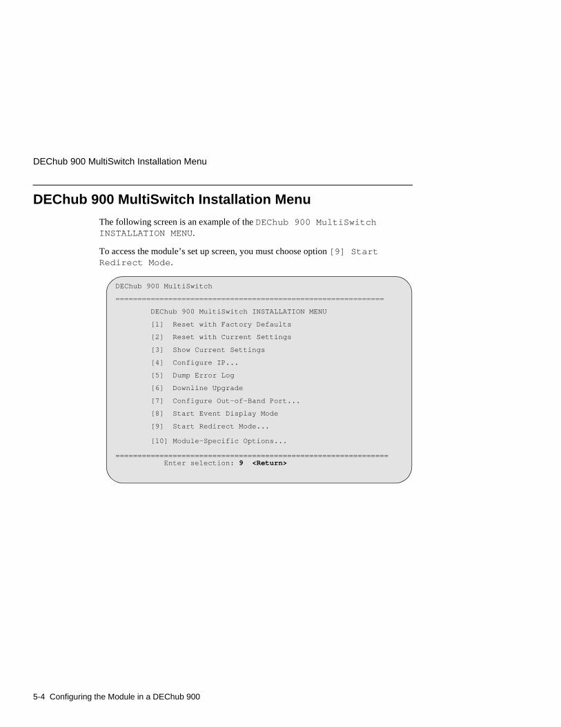
DEChub 900 MultiSwitch Installation Menu
5-4 Configuring the Module in a DEChub 900
DEChub 900 MultiSwitch Installation Menu
The following screen is an example of the DEChub 900 MultiSwitch INSTALLATION MENU.
To access the module’s set up screen, you must choose option [9] Start Redirect Mode.
DEChub 900 MultiSwitch
=============================================================
DEChub 900 MultiSwitch INSTALLATION MENU
[1] Reset with Factory Defaults
[2] Reset with Current Settings
[3] Show Current Settings
[4] Configure IP...
[5] Dump Error Log
[6] Downline Upgrade
[7] Configure Out-of-Band Port...
[8] Start Event Display Mode
[9] Start Redirect Mode...
[10] Module-Specific Options...
============================================================== Enter selection: 9 <Return>
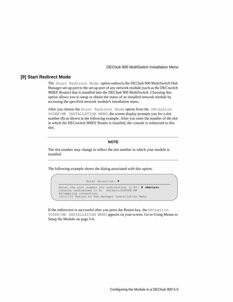
Configuring the Module in a DEChub 900 5-5
DEChub 900 MultiSwitch Installation Menu
[9] Start Redirect ModeThe Start Redirect Mode option redirects the DEChub 900 MultiSwitch Hub Manager set-up port to the set-up port of any network module (such as the DECswitch 900EF Router) that is installed into the DEChub 900 MultiSwitch. Choosing this option allows you to setup or obtain the status of an installed network module by accessing the specified network module’s installation menu.
After you choose the Start Redirect Mode option from the DECswitch 900EF/MP INSTALLATION MENU, the screen display prompts you for a slot number (8) as shown in the following example. After you enter the number of the slot in which the DECswitch 900EF Router is installed, the console is redirected to this slot.
NOTE
The slot number may change to reflect the slot number in which your module is installed.
The following example shows the dialog associated with this option.
If the redirection is successful after you press the Return key, the DECswitch 900EF/MP INSTALLATION MENU appears on your screen. Go to Using Menus to Setup the Module on page 5-6.
Enter selection: 9=============================================================Enter the slot number for redirection (1-8): 8 <Return>Console redirected to 8: DECswitch900EF/MPAttempting connection [Ctrl/C] Return to Hub Manager Installation Menu

Using Menus to Setup the Module
5-6 Configuring the Module in a DEChub 900
Using Menus to Setup the Module
This section describes the options that are available from the DECswitch 900EF/MP INSTALLATION MENU when the module is installed in the DEChub 900 MultiSwitch.
The following example shows the menu options available when the module is setup with factory defaults.
NOTE
The /MP that appears in menus will be replaced with /IP when using the Internet Protocol package.
DECswitch900EF/MP - slot 8============================================================= DECswitch 900EF/MP INSTALLATION MENU
[1] Restart with Factory Defaults [2] Restart with Current Settings [3] Show Current Settings [4] IP Configuration [5] Go to Local Console
============================================================= Enter selection :
[Ctrl/C] Return to Hub Manager Installation Menu

Configuring the Module in a DEChub 900 5-7
Using Menus to Setup the Module
If the module was previously configured, the following example shows the dialog associated with this option.
NOTE
The Out-of-Band and In-Band values are listed only if one or more IP parameters have been set.
The following pages describe the installation menu options.
Options Page
[1] Restart with Factory Defaults 5-8
[2] Restart with Current Settings 5-9
[3] Show Current Settings 5-10
[4] IP Configuration 5-11
Go to Local Console 5-16
DECswitch900EF/MP - slot 8============================================================= DECswitch 900EF/MP INSTALLATION MENU* * * * * * * * * * * * * * * * * * * * * * * * * * * * * * ** To fully manage this router telnet to one of the ** following IP addresses or select item [3] below. ** Out-of-Band: Not Configured ** In-Band : 13.24.1.254 ** * * * * * * * * * * * * * * * * * * * * * * * * * * * * * * [1] Restart with Factory Defaults [2] Restart with Current Settings [3] Go to Local Console [Ctrl/C] Return to Hub Manager Installation Menu============================================================= Enter selection:
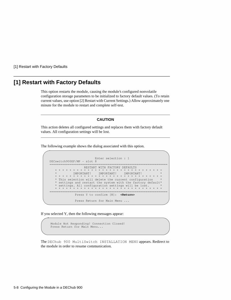
[1] Restart with Factory Defaults
5-8 Configuring the Module in a DEChub 900
[1] Restart with Factory Defaults
This option restarts the module, causing the module’s configured nonvolatile configuration storage parameters to be initialized to factory default values. (To retain current values, use option [2] Restart with Current Settings.) Allow approximately one minute for the module to restart and complete self-test.
CAUTION
This action deletes all configured settings and replaces them with factory default values. All configuration settings will be lost.
The following example shows the dialog associated with this option.
If you selected Y, then the following messages appear:
The DEChub 900 MultiSwitch INSTALLATION MENU appears. Redirect to the module in order to resume communication.
Enter selection : 1DECswitch900EF/MP - slot 8================================================================= RESTART WITH FACTORY DEFAULTS * * * * * * * * * * * * * * * * * * * * * * * * * * * * * * * IMPORTANT! IMPORTANT! IMPORTANT! * * * * * * * * * * * * * * * * * * * * * * * * * * * * * * * * This selection will delete the current configuration * * settings and restart the system with the factory default* * settings. All configuration settings will be lost. * * * * * * * * * * * * * * * * * * * * * * * * * * * * * * *================================================================= Press Y to confirm [N]: <Return>
Press Return for Main Menu ...
Module Not Responding! Connection Closed! Press Return for Main Menu...

Configuring the Module in a DEChub 900 5-9
[2] Restart with Current Settings
[2] Restart with Current Settings
This option restarts the module but leaves the module’s configured nonvolatile configuration storage parameters at their current values.
NOTE
Allow approximately 1 minute for the module to Restart.
The following example shows the dialog associated with this option.
The DEChub 900 MultiSwitch INSTALLATION MENU appears. Redirect to the module in order to resume communication.
Enter selection: 2
DECswitch900EF/MP - slot 8
=============================================================
RESTART WITH CURRENT SETTINGS
This selection will restart your system with the current
configuration settings.
=============================================================
Press Y to confirm [N] : Y <Return>
Press Return for Main Menu ...
Module Not Responding! Connection Closed!

[3] Show Current Settings
5-10 Configuring the Module in a DEChub 900
[3] Show Current Settings
This option shows the module’s current settings. If the module is being configured for the first time, some of the fields will be blank.
The following example shows the dialog associated with this option.
Enter selection : 3
DECswitch900EF/MP - slot 8
=================================================================
DECswitch900EF/MP,MP Brouter:6 Enet 1 Fddi,HW=v1/2,#1489,SW=v2.0.000
SysUpTime : 00:00:52 28 resets
SNMP Read/Write Community : thepublic
Out-of-Band Management RTS : Disabled
Default Gateway : 16.126.16.254
-----------------------------------------------------------------
Interface IP Address Subnet Mask Other Info
Ethernet 16.126.16.116 255.255.255.0
=================================================================
Press Return for Main Menu ...
Out-of-Band 16.126.16.114 Not Configured
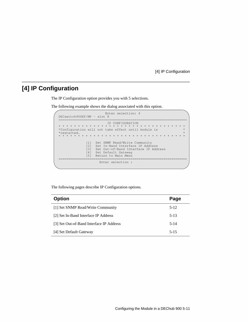
Configuring the Module in a DEChub 900 5-11
[4] IP Configuration
[4] IP Configuration
The IP Configuration option provides you with 5 selections.
The following example shows the dialog associated with this option.
The following pages describe IP Configuration options.
Option Page
[1] Set SNMP Read/Write Community 5-12
[2] Set In-Band Interface IP Address 5-13
[3] Set Out-of-Band Interface IP Address 5-14
[4] Set Default Gateway 5-15
Enter selection: 4DECswitch900EF/MP - slot 8================================================================== IP CONFIGURATION* * * * * * * * * * * * * * * * * * * * * * * * * * * * * * * * **Configuration will not take effect until module is **restarted. ** * * * * * * * * * * * * * * * * * * * * * * * * * * * * * * * *
[1] Set SNMP Read/Write Community [2] Set In-Band Interface IP Address [3] Set Out-of-Band Interface IP Address [4] Set Default Gateway [5] Return to Main Menu================================================================== Enter selection :
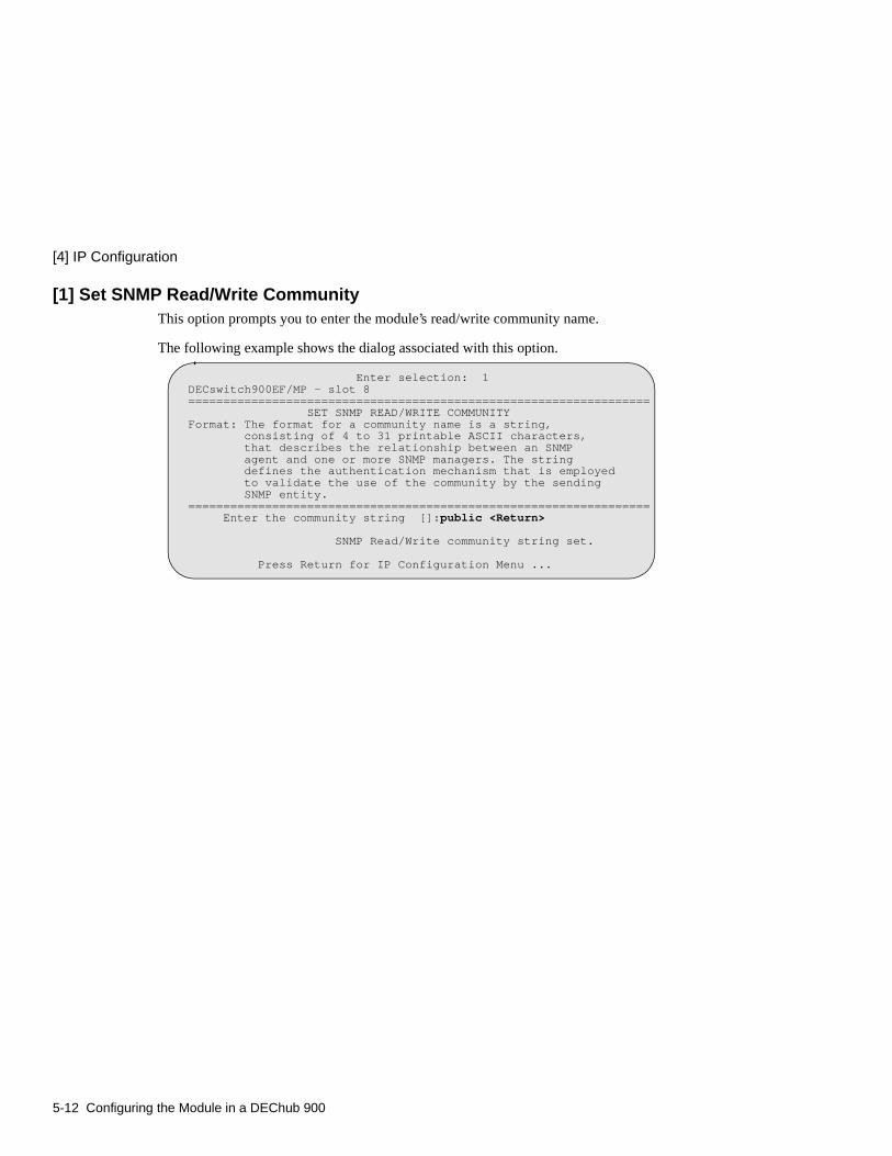
[4] IP Configuration
5-12 Configuring the Module in a DEChub 900
[1] Set SNMP Read/Write CommunityThis option prompts you to enter the module’s read/write community name.
The following example shows the dialog associated with this option.
Enter selection: 1DECswitch900EF/MP - slot 8================================================================== SET SNMP READ/WRITE COMMUNITYFormat: The format for a community name is a string, consisting of 4 to 31 printable ASCII characters, that describes the relationship between an SNMP agent and one or more SNMP managers. The string defines the authentication mechanism that is employed to validate the use of the community by the sending SNMP entity.================================================================== Enter the community string []:public <Return>
SNMP Read/Write community string set.
Press Return for IP Configuration Menu ...
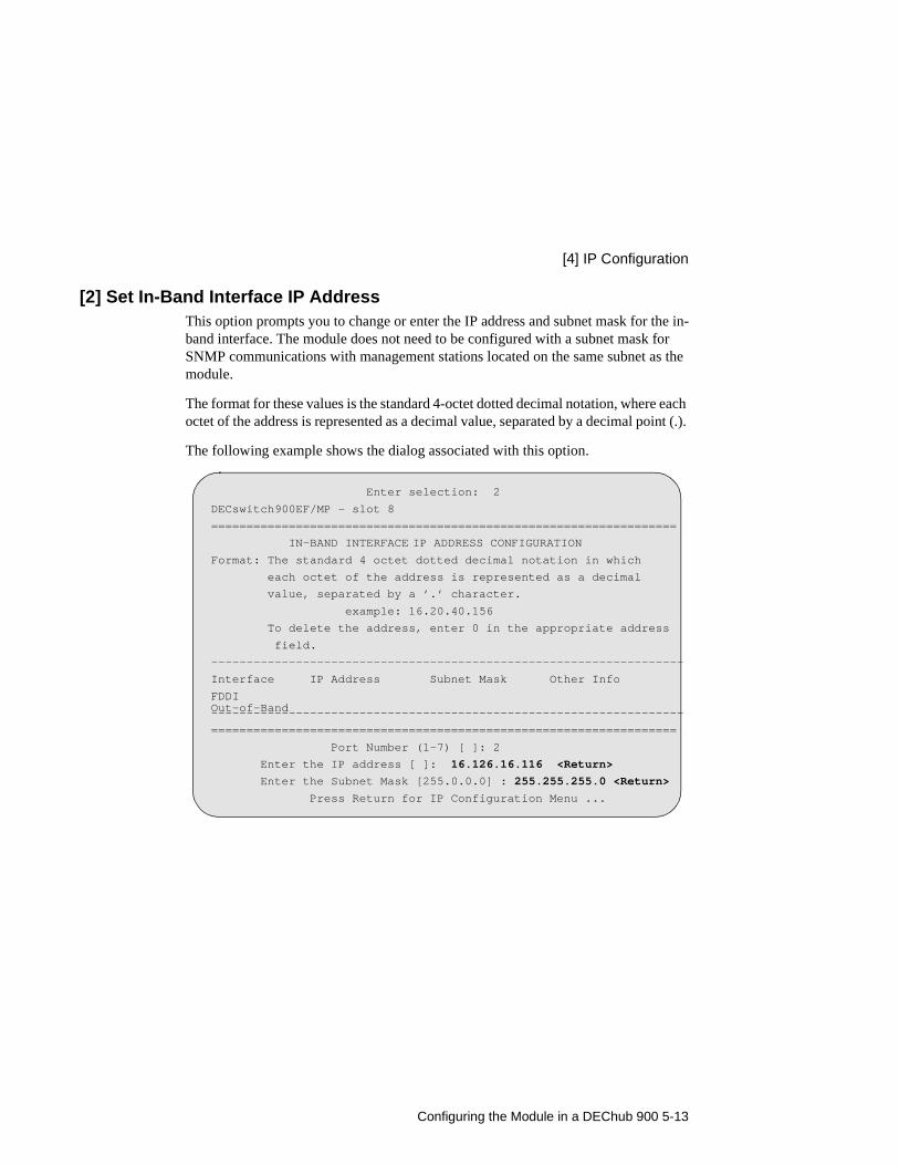
Configuring the Module in a DEChub 900 5-13
[4] IP Configuration
[2] Set In-Band Interface IP AddressThis option prompts you to change or enter the IP address and subnet mask for the in-band interface. The module does not need to be configured with a subnet mask for SNMP communications with management stations located on the same subnet as the module.
The format for these values is the standard 4-octet dotted decimal notation, where each octet of the address is represented as a decimal value, separated by a decimal point (.).
The following example shows the dialog associated with this option.
Enter selection: 2
DECswitch900EF/MP - slot 8
==================================================================
IN-BAND INTERFACE IP ADDRESS CONFIGURATIONFormat: The standard 4 octet dotted decimal notation in which
each octet of the address is represented as a decimal
value, separated by a ’.’ character.
example: 16.20.40.156
To delete the address, enter 0 in the appropriate address
field.
-------------------------------------------------------------------
Interface IP Address Subnet Mask Other Info
FDDI
-------------------------------------------------------------------
==================================================================
Port Number (1-7) [ ]: 2
Enter the IP address [ ]: 16.126.16.116 <Return>
Enter the Subnet Mask [255.0.0.0] : 255.255.255.0 <Return>
Press Return for IP Configuration Menu ...
Out-of-Band
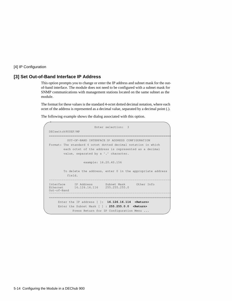
[4] IP Configuration
5-14 Configuring the Module in a DEChub 900
[3] Set Out-of-Band Interface IP AddressThis option prompts you to change or enter the IP address and subnet mask for the out-of-band interface. The module does not need to be configured with a subnet mask for SNMP communications with management stations located on the same subnet as the module.
The format for these values is the standard 4-octet dotted decimal notation, where each octet of the address is represented as a decimal value, separated by a decimal point (.).
The following example shows the dialog associated with this option.
Enter selection: 3
DECswitch900EF/MP
===================================================================
OUT-OF-BAND INTERFACE IP ADDRESS CONFIGURATIONFormat: The standard 4 octet dotted decimal notation in which
each octet of the address is represented as a decimal
value, separated by a ’.’ character.
example: 16.20.40.156
To delete the address, enter 0 in the appropriate address
field.
-------------------------------------------------------------------
Interface IP Address Subnet Mask Other Info
-------------------------------------------------------------------
===================================================================
Enter the IP address [ ]: 16.126.16.114 <Return>
Enter the Subnet Mask [ ] : 255.255.0.0 <Return>
Press Return for IP Configuration Menu ...
Ethernet 16.126.16.116 255.255.255.0Out-of-Band

Configuring the Module in a DEChub 900 5-15
[4] IP Configuration
[4] Set Default GatewayThis option sets the default gateway, if necessary. This is the address of a router that the module will use when communicating to a remote host. The default gateway address must be in the same subnet as your in-band address.
The following example shows the dialog associated with this option.
Enter selection : 4
DECswitch900EF/MP - slot 8
==================================================================
SET IN-BAND INTERFACE DEFAULT GATEWAY ADDRESS
Format: The standard 4 octet dotted decimal notation in which
each octet of the address is represented as a decimal
value, separated by a ’.’ character.
example: 16.20.40.156
To delete the address, enter 0 in the appropriate address
field.
==================================================================
Default Gateway [] : 16.126.16.254 <Return>
Default Gateway Address Set.
Press Return for IP Configuration Menu ...
Go to Local Console
5-16 Configuring the Module in a DEChub 900
Go to Local Console
This option lets you configure the module.You must configure the module before it is operational. The Go to Local Console option provides two different configuration methods, depending on whether the module has been setup with factory defaults or has been previously configured.
If the module has been setup with factory defaults, then this is option [5] Go to Local Console from the DECswitch900EF/MP INSTALLATION MENU. This option runs a quick configuration interactive question and answer dialog. This method (qconfig) allows fast configuration of interfaces, basic bridging, and IP configuration.
If the module has been previously configured, then this is option [3] Go to Local Console from the installation menu. This option allows you to configure the module using commands to configure interfaces, bridging, and routing protocol.
NOTE
You must restart the module in order for the configuration changes to take effect. The hub will close the connection to the selected slot after restart, but you can resume communication with the desired slot after redirection.
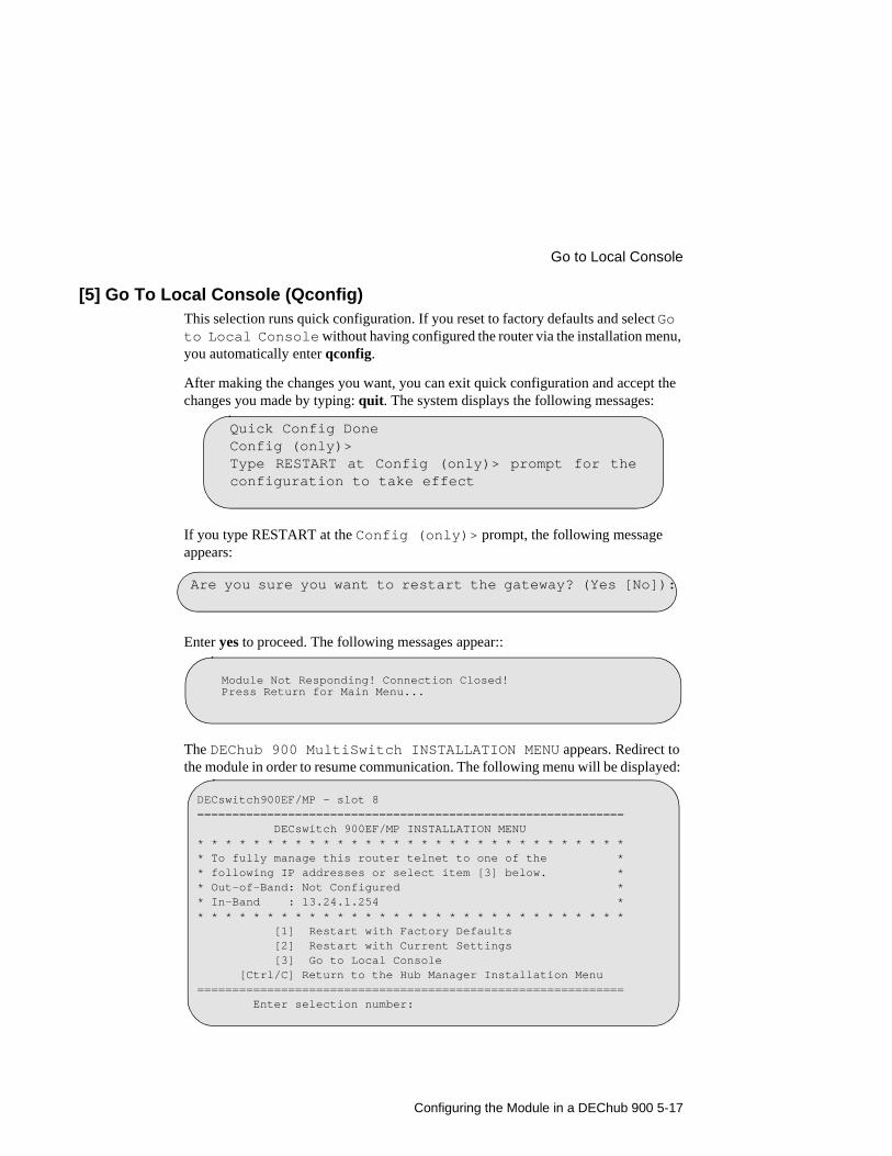
Configuring the Module in a DEChub 900 5-17
Go to Local Console
[5] Go To Local Console (Qconfig)This selection runs quick configuration. If you reset to factory defaults and select Go to Local Console without having configured the router via the installation menu, you automatically enter qconfig.
After making the changes you want, you can exit quick configuration and accept the changes you made by typing: quit. The system displays the following messages:
If you type RESTART at the Config (only)> prompt, the following message appears:
Enter yes to proceed. The following messages appear::
The DEChub 900 MultiSwitch INSTALLATION MENU appears. Redirect to the module in order to resume communication. The following menu will be displayed:
Quick Config DoneConfig (only)>Type RESTART at Config (only)> prompt for theconfiguration to take effect
Are you sure you want to restart the gateway? (Yes [No]):
Module Not Responding! Connection Closed! Press Return for Main Menu...
DECswitch900EF/MP - slot 8============================================================= DECswitch 900EF/MP INSTALLATION MENU* * * * * * * * * * * * * * * * * * * * * * * * * * * * * * ** To fully manage this router telnet to one of the ** following IP addresses or select item [3] below. ** Out-of-Band: Not Configured ** In-Band : 13.24.1.254 ** * * * * * * * * * * * * * * * * * * * * * * * * * * * * * * [1] Restart with Factory Defaults [2] Restart with Current Settings [3] Go to Local Console [Ctrl/C] Return to the Hub Manager Installation Menu============================================================= Enter selection number:

Go to Local Console
5-18 Configuring the Module in a DEChub 900
[3] Go To Local Console (Commands)If you have configured the module, then the following installation menu appears. Select [3] Go To Local Console to modify the configuration or to monitor the module.
The system displays copyright statements and the following prompt:
See Chapter 6, Configuration Commands for information on configuring FDDI, Ethernet, OBM and VLAN interfaces. See Chapter 7, Monitoring Commands for information about monitoring these interfaces.
DECswitch900EF/MP - slot 8============================================================= DECswitch 900EF/MP INSTALLATION MENU* * * * * * * * * * * * * * * * * * * * * * * * * * * * * * ** To fully manage this router telnet to one of the ** following IP addresses or select item [3] below. ** Out-of-Band: Not Configured ** In-Band : 13.24.1.254 ** * * * * * * * * * * * * * * * * * * * * * * * * * * * * * * [1] Restart with Factory Defaults [2] Restart with Current Settings [3] Go to Local Console [Ctrl/C] Return to the Hub Manager Installation Menu============================================================= Enter selection number: 3 <Return>
MOS Operator Control*

Configuration Commands 6-1
Chapter 6
Configuration Commands
Overview
IntroductionAfter you have installed the DECswitch 900EF Router, you will need to configure the following.
• FDDI Port
• Ethernet Port
• OBM Port
• VLAN Interfaces
The instructions provided in this chapter describe how to setup and configure these ports and interfaces. For more information about configuration commands, see the Network Interface Operations Guide.
In this chapter
Topic Page
Accessing Configuration Commands 6-2
Configuring FDDI Port Connection 6-3
Configuring Ethernet Port Connection 6-4
Configuring OBM Port 6-5
Configuring Virtual LANs 6-6

Accessing Configuration Commands
6-2 Configuration Commands
Accessing Configuration Commands
This section describes configuration commands that are unique to the DECswitch 900EF Router. To begin configuring the module, at the * prompt enter the following command:
* talk 6
To configure the module using CONFIG commands, refer to the following sections.
To Exit and RestartWhen you modify parameters, you must restart the module for the change to take effect. Enter the following commands in the order shown:
If you need to configure additional software, refer to the Distributed Routing Software guides.
Option Page
Configuring FDDI Port Connection 6-3
Configuring Ethernet Port Connection 6-4
Configuring OBM Port 6-5
Configuring Virtual LANs 6-6
At the prompt Enter the Command
FDDI Config> or ETH Config> orVLAN Config> orVI Config>
exit to return to the Config> prompt, or control/p to return to the * prompt
Config> control/p
* restart
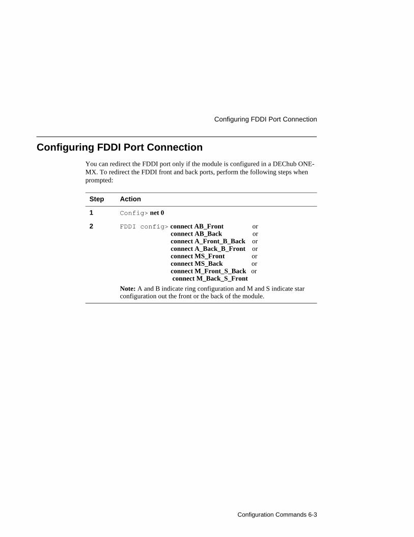
Configuration Commands 6-3
Configuring FDDI Port Connection
Configuring FDDI Port Connection
You can redirect the FDDI port only if the module is configured in a DEChub ONE-MX. To redirect the FDDI front and back ports, perform the following steps when prompted:
Step Action
1 Config> net 0
2 FDDI config> connect AB_Front or connect AB_Back or connect A_Front_B_Back or connect A_Back_B_Front or connect MS_Front or connect MS_Back or connect M_Front_S_Back or connect M_Back_S_Front
Note: A and B indicate ring configuration and M and S indicate star configuration out the front or the back of the module.
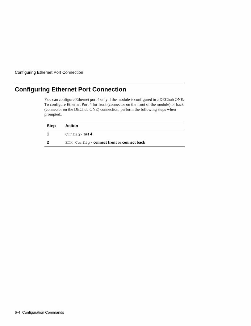
Configuring Ethernet Port Connection
6-4 Configuration Commands
Configuring Ethernet Port Connection
You can configure Ethernet port 4 only if the module is configured in a DEChub ONE. To configure Ethernet Port 4 for front (connector on the front of the module) or back (connector on the DEChub ONE) connection, perform the following steps when prompted:.
Step Action
1 Config> net 4
2 ETH Config> connect front or connect back
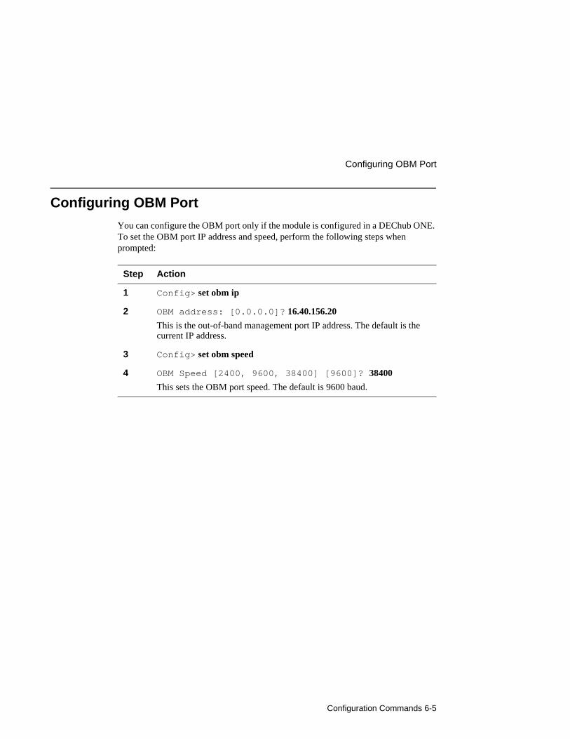
Configuration Commands 6-5
Configuring OBM Port
Configuring OBM Port
You can configure the OBM port only if the module is configured in a DEChub ONE. To set the OBM port IP address and speed, perform the following steps when prompted:
Step Action
1 Config> set obm ip
2 OBM address: [0.0.0.0]? 16.40.156.20
This is the out-of-band management port IP address. The default is the current IP address.
3 Config> set obm speed
4 OBM Speed [2400, 9600, 38400] [9600]? 38400
This sets the OBM port speed. The default is 9600 baud.

Configuring Virtual LANs
6-6 Configuration Commands
Configuring Virtual LANs
To create a virtual LAN, you must complete the following tasks:
1) Create a VLAN, providing a name and a list of bridge ports that will be included in the VLAN. A virtual interface (VI) number and a VLAN number are assigned to the VLAN. You can create up to 7 VLANs, which are assigned VI numbers 7-13. Ports that are not explicitly assigned to a VLAN belong to a “default” VLAN named Unconfigured.
2) Assign a frame type to the VLAN interface. The frame type allowed depends on whether the bridge ports in the VLAN are all Ethernet, all FDDI, or else a mix of the two.
3) If a port that is included in a VLAN uses IPX, then you must specify the port’s frame encapsulation type as part of its IPX configuration.
This section contains the following topics:
Topic Page
Creating, Deleting, and Modifying VLANs 6-7
Assigning Frame Types to VLANs 6-10
Assigning IPX Encapsulation to VLAN Ports 6-11
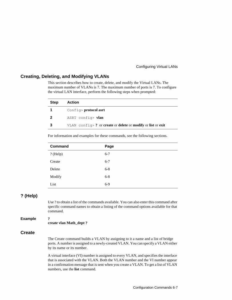
Configuration Commands 6-7
Configuring Virtual LANs
Creating, Deleting, and Modifying VLANsThis section describes how to create, delete, and modify the Virtual LANs. The maximum number of VLANs is 7. The maximum number of ports is 7. To configure the virtual LAN interface, perform the following steps when prompted:
For information and examples for these commands, see the following sections.
? (Help)Use ? to obtain a list of the commands available. You can also enter this command after specific command names to obtain a listing of the command options available for that command.
Example ?create vlan Math_dept ?
CreateThe Create command builds a VLAN by assigning to it a name and a list of bridge ports. A number is assigned to a newly-created VLAN. You can specify a VLAN either by its name or its number.
A virtual interface (VI) number is assigned to every VLAN, and specifies the interface that is associated with the VLAN. Both the VLAN number and the VI number appear in a confirmation message that is sent when you create a VLAN. To get a list of VLAN numbers, use the list command.
Step Action
1 Config> protocol asrt
2 ASRT config> vlan
3 VLAN config> ? or create or delete or modify or list or exit
Command Page
? (Help) 6-7
Create 6-7
Delete 6-8
Modify 6-8
List 6-9

Configuring Virtual LANs
6-8 Configuration Commands
Syntax create vlan name [ports] port-list
name must be a maximum of 32 ASCII characters, including at least one alphabetic character. VLAN names must be unique.
port-list is a list of bridge ports that you want to include in the VLAN. You must specify valid bridge ports. To add bridge ports, return to the ASRT Config> prompt and use the add port command. If you delete a bridge port which is in a VLAN, it will be removed from the VLAN.
Ports can be specified in the following ways:
1-71,2,3,41
Example create vlan Math_dept ports 1-3
VLAN 3 created (VI number 8)
Example create vlan Eng_dept 6, 7
VLAN 4 created (VI number 9)
DeleteUse Delete to delete a VLAN, specifying either its name or number. Deleting a VLAN does not affect the VLAN number or VI number assignments of the remaining VLANs. Use the list all command to view all VLANs.
Syntax delete vlan number | name
Example delete vlan Math_dept
VLAN 3 deleted (VI number 8)
Example delete vlan 4
VLAN 4 deleted (VI number 9)
ModifyThe Modify command modifies a VLAN’s name and port list. Specify the VLAN either by its name or number.
Syntax modify vlan number | name new-name new-port-list
new-name must be a maximum of 32 ASCII characters, including at least one alphabetic character. VLAN names must be unique. If you do not want to change the VLAN name, specify the original name.

Configuration Commands 6-9
Configuring Virtual LANs
new-port-list is a list of bridge ports that you want to include in the VLAN. You must specify valid bridge ports. To add bridge ports, return to the ASRT Config> prompt and use the add port command. If you delete a bridge port which is in a VLAN, it will be removed from the VLAN. If you do not want to change the list of ports, do not specify a new list.
Ports can be specified in the following ways:
1-71,2,3,41
Example modify vlan Eng_dept Eng_dept 5, 6, 7
VLAN 4 modified (VI number 9)
Example modify vlan 4 Eng_dept 3
VLAN 4 modified (VI number 9)
ListThe List command displays all information about existing VLANs. Specify the VLAN you want to display, or else list them all. If you have not assigned all ports to a VLAN, the unassigned ports will appear as part of a VLAN named Unconfigured.
Syntax list vlan name | number | all
Example list vlan Sci_dept
# Name Ports VI Number4 Sci_dept 3,4 9
Example list vlan 4
# Name Ports VI Number4 Sci_dept 3,4 9
Example list vlan all
# Name Ports VI Number1 Unconfigured 1, 2, 5, 6 4 Sci_dept 3,4 9
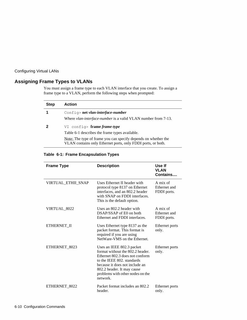
Configuring Virtual LANs
6-10 Configuration Commands
Assigning Frame Types to VLANsYou must assign a frame type to each VLAN interface that you create. To assign a frame type to a VLAN, perform the following steps when prompted:
Table 6-1: Frame Encapsulation Types
Step Action
1 Config> net vlan-interface-number
Where vlan-interface-number is a valid VLAN number from 7-13.
2 VI config> frame frame-type
Table 6-1 describes the frame types available.
Note: The type of frame you can specify depends on whether the VLAN contains only Ethernet ports, only FDDI ports, or both.
Frame Type Description Use If VLAN Contains....
VIRTUAL_ETHII_SNAP Uses Ethernet II header with protocol type 8137 on Ethernet interfaces, and an 802.2 header with SNAP on FDDI interfaces. This is the default option.
A mix of Ethernet and FDDI ports.
VIRTUAL_8022 Uses an 802.2 header with DSAP/SSAP of E0 on both Ethernet and FDDI interfaces.
A mix of Ethernet and FDDI ports.
ETHERNET_II Uses Ethernet type 8137 as the packet format. This format is required if you are using NetWare-VMS on the Ethernet.
Ethernet ports only.
ETHERNET_8023 Uses an IEEE 802.3 packet format without the 802.2 header. Ethernet 802.3 does not conform to the IEEE 802. standards because it does not include an 802.2 header. It may cause problems with other nodes on the network.
Ethernet ports only.
ETHERNET_8022 Packet format includes an 802.2 header.
Ethernet ports only.
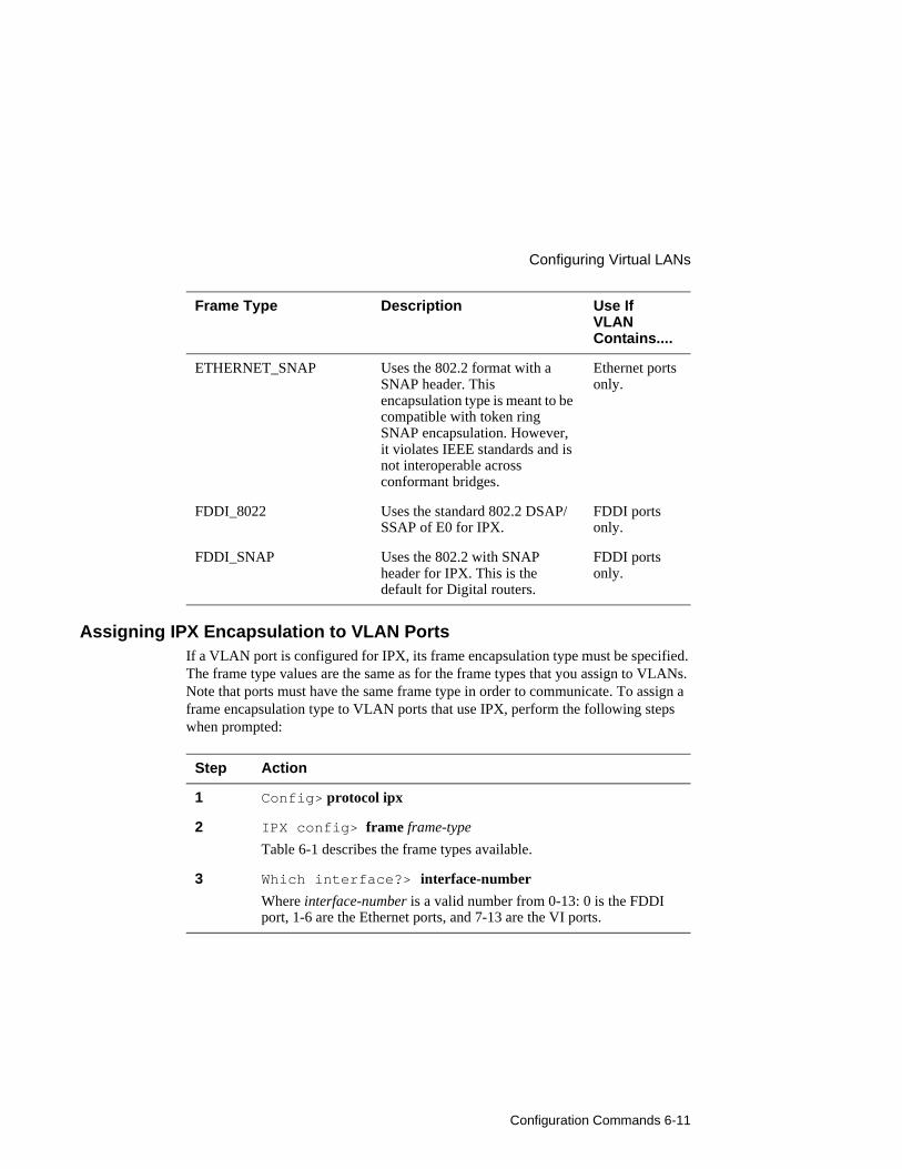
Configuration Commands 6-11
Configuring Virtual LANs
Assigning IPX Encapsulation to VLAN PortsIf a VLAN port is configured for IPX, its frame encapsulation type must be specified. The frame type values are the same as for the frame types that you assign to VLANs. Note that ports must have the same frame type in order to communicate. To assign a frame encapsulation type to VLAN ports that use IPX, perform the following steps when prompted:
ETHERNET_SNAP Uses the 802.2 format with a SNAP header. This encapsulation type is meant to be compatible with token ring SNAP encapsulation. However, it violates IEEE standards and is not interoperable across conformant bridges.
Ethernet ports only.
FDDI_8022 Uses the standard 802.2 DSAP/SSAP of E0 for IPX.
FDDI ports only.
FDDI_SNAP Uses the 802.2 with SNAP header for IPX. This is the default for Digital routers.
FDDI ports only.
Step Action
1 Config> protocol ipx
2 IPX config> frame frame-type
Table 6-1 describes the frame types available.
3 Which interface?> interface-number
Where interface-number is a valid number from 0-13: 0 is the FDDI port, 1-6 are the Ethernet ports, and 7-13 are the VI ports.
Frame Type Description Use If VLAN Contains....

Monitoring Commands 7-1
Chapter 7
Monitoring Commands
Overview
IntroductionThis chapter describes commands used to monitor your DECswitch 900EF Router when it is installed in either a standalone unit DEChub ONE docking station or a DEChub 900 MultiSwitch. You should only use this chapter if the module has been previously configured.
In this chapter
Topic Page
Accessing Monitoring Commands 7-2
Listing All Interfaces 7-3
Monitoring FDDI Port Connection 7-4
Monitoring Ethernet Port Connection 7-5
Monitoring Virtual Interfaces 7-6
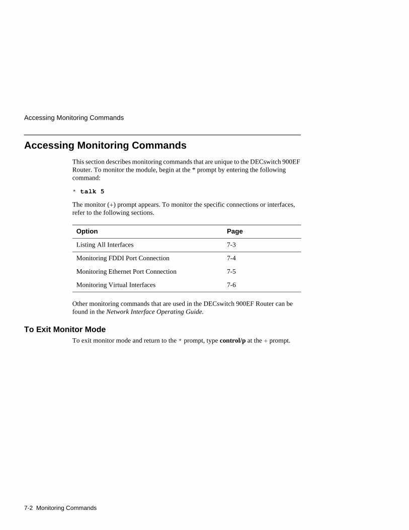
Accessing Monitoring Commands
7-2 Monitoring Commands
Accessing Monitoring Commands
This section describes monitoring commands that are unique to the DECswitch 900EF Router. To monitor the module, begin at the * prompt by entering the following command:
* talk 5
The monitor (+) prompt appears. To monitor the specific connections or interfaces, refer to the following sections.
Other monitoring commands that are used in the DECswitch 900EF Router can be found in the Network Interface Operating Guide.
To Exit Monitor ModeTo exit monitor mode and return to the * prompt, type control/p at the + prompt.
Option Page
Listing All Interfaces 7-3
Monitoring FDDI Port Connection 7-4
Monitoring Ethernet Port Connection 7-5
Monitoring Virtual Interfaces 7-6
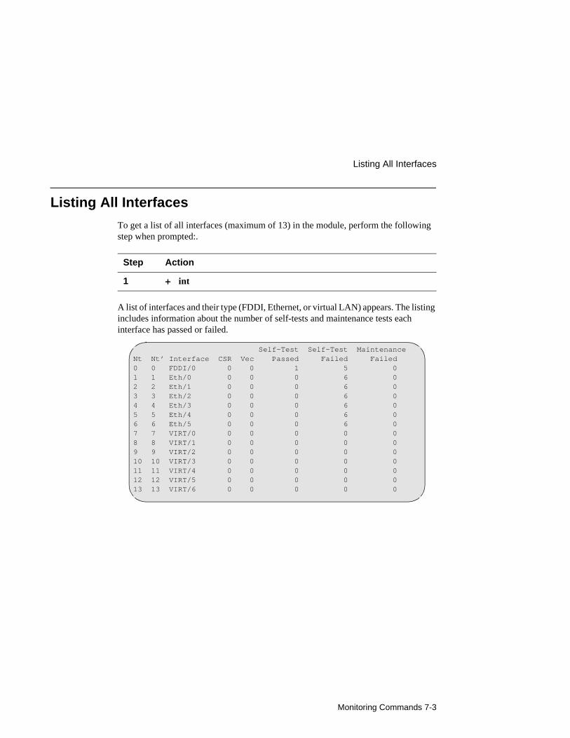
Monitoring Commands 7-3
Listing All Interfaces
Listing All Interfaces
To get a list of all interfaces (maximum of 13) in the module, perform the following step when prompted:.
A list of interfaces and their type (FDDI, Ethernet, or virtual LAN) appears. The listing includes information about the number of self-tests and maintenance tests each interface has passed or failed.
Step Action
1 + int
Self-Test Self-Test MaintenanceNt Nt’ Interface CSR Vec Passed Failed Failed0 0 FDDI/0 0 0 1 5 01 1 Eth/0 0 0 0 6 02 2 Eth/1 0 0 0 6 03 3 Eth/2 0 0 0 6 04 4 Eth/3 0 0 0 6 05 5 Eth/4 0 0 0 6 06 6 Eth/5 0 0 0 6 07 7 VIRT/0 0 0 0 0 08 8 VIRT/1 0 0 0 0 09 9 VIRT/2 0 0 0 0 010 10 VIRT/3 0 0 0 0 011 11 VIRT/4 0 0 0 0 012 12 VIRT/5 0 0 0 0 013 13 VIRT/6 0 0 0 0 0
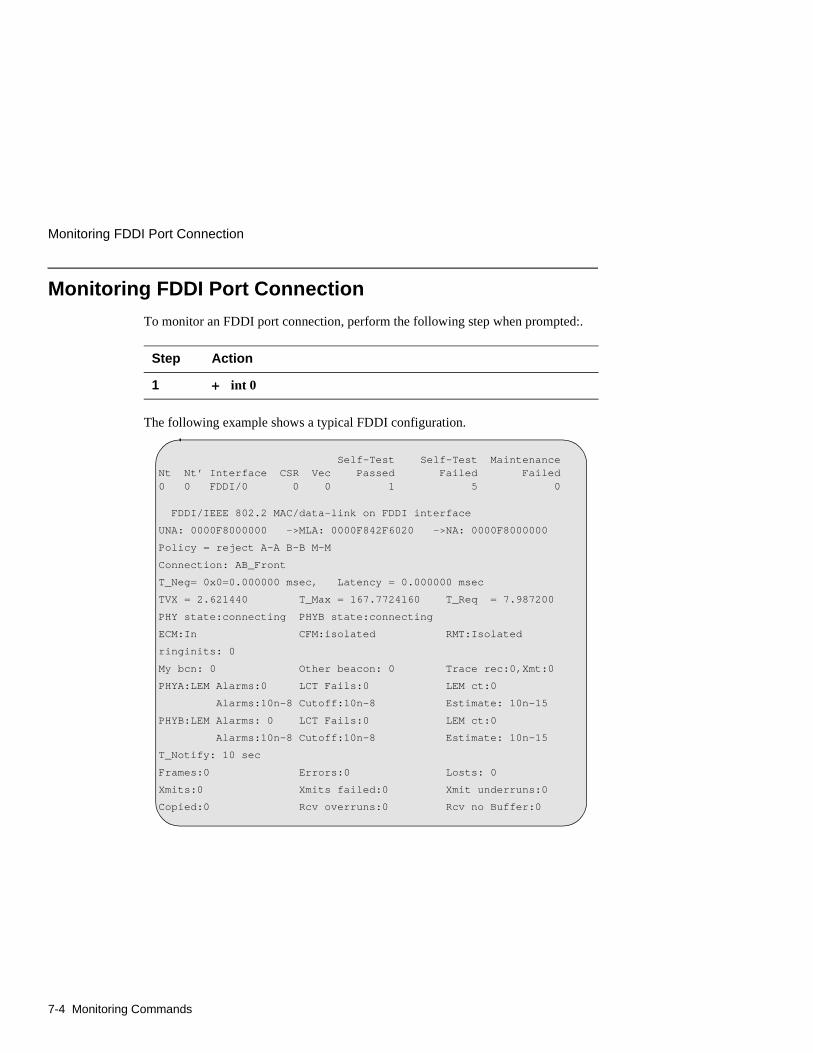
Monitoring FDDI Port Connection
7-4 Monitoring Commands
Monitoring FDDI Port Connection
To monitor an FDDI port connection, perform the following step when prompted:.
The following example shows a typical FDDI configuration.
Step Action
1 + int 0
Self-Test Self-Test MaintenanceNt Nt’ Interface CSR Vec Passed Failed Failed0 0 FDDI/0 0 0 1 5 0
FDDI/IEEE 802.2 MAC/data-link on FDDI interface
UNA: 0000F8000000 ->MLA: 0000F842F6020 ->NA: 0000F8000000
Policy = reject A-A B-B M-M
Connection: AB_Front
T_Neg= 0x0=0.000000 msec, Latency = 0.000000 msec
TVX = 2.621440 T_Max = 167.7724160 T_Req = 7.987200
PHY state:connecting PHYB state:connecting
ECM:In CFM:isolated RMT:Isolated
ringinits: 0
My bcn: 0 Other beacon: 0 Trace rec:0,Xmt:0
PHYA:LEM Alarms:0 LCT Fails:0 LEM ct:0
Alarms:10n-8 Cutoff:10n-8 Estimate: 10n-15
PHYB:LEM Alarms: 0 LCT Fails:0 LEM ct:0
Alarms:10n-8 Cutoff:10n-8 Estimate: 10n-15
T_Notify: 10 sec
Frames:0 Errors:0 Losts: 0
Xmits:0 Xmits failed:0 Xmit underruns:0
Copied:0 Rcv overruns:0 Rcv no Buffer:0
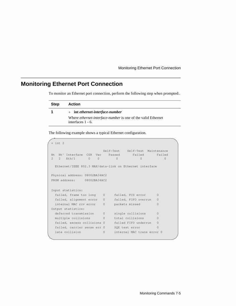
Monitoring Commands 7-5
Monitoring Ethernet Port Connection
Monitoring Ethernet Port Connection
To monitor an Ethernet port connection, perform the following step when prompted:.
The following example shows a typical Ethernet configuration.
Step Action
1 + int ethernet-interface-number
Where ethernet-interface-number is one of the valid Ethernet interfaces 1 - 6.
+ int 2
Self-Test Self-Test MaintenanceNt Nt’ Interface CSR Vec Passed Failed Failed2 2 Eth/1 0 0 0 0 0
Ethernet/IEEE 802.3 MAX/data-link on Ethernet interface
Physical address: 08002BA34AC2
PROM address: 08002BA34AC2
Input statistics:
failed, frame too long 0 failed, FCS error 0
failed, alignment error 0 failed, FIFO overrun 0
internal MAC rcv error 0 packets missed 0
Output statistics:
deferred transmission 0 single collisions 0
multiple collisions 0 total collisions 0
failed, excess collisions 0 failed FIFO underrun 0
failed, carrier sense err 0 SQE test error 0
late collision 0 internal MAC trans error 0
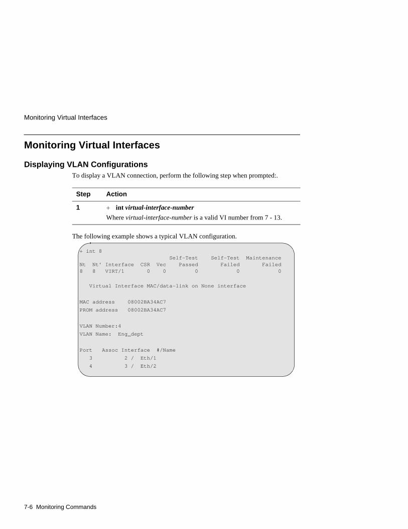
Monitoring Virtual Interfaces
7-6 Monitoring Commands
Monitoring Virtual Interfaces
Displaying VLAN ConfigurationsTo display a VLAN connection, perform the following step when prompted:.
The following example shows a typical VLAN configuration.
Step Action
1 + int virtual-interface-number
Where virtual-interface-number is a valid VI number from 7 - 13.
+ int 8 Self-Test Self-Test MaintenanceNt Nt’ Interface CSR Vec Passed Failed Failed8 8 VIRT/1 0 0 0 0 0
Virtual Interface MAC/data-link on None interface
MAC address 08002BA34AC7
PROM address 08002BA34AC7
VLAN Number:4
VLAN Name: Eng_dept
Port Assoc Interface #/Name
3 2 / Eth/1
4 3 / Eth/2
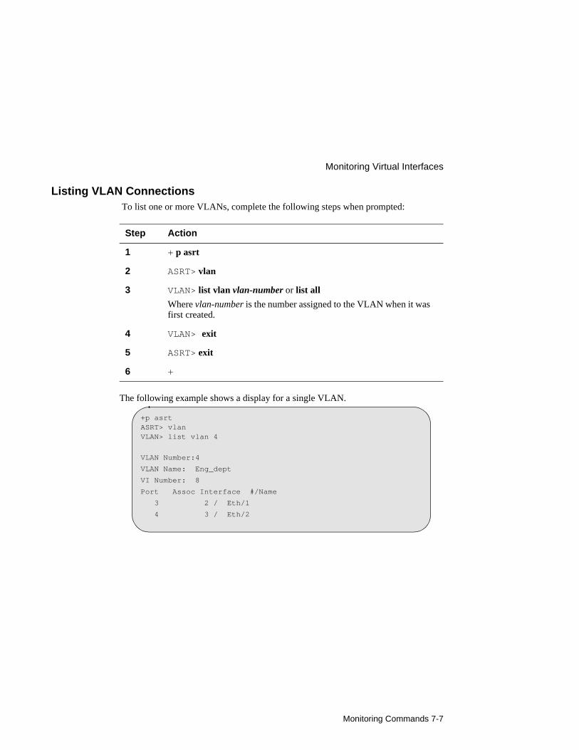
Monitoring Commands 7-7
Monitoring Virtual Interfaces
Listing VLAN Connections To list one or more VLANs, complete the following steps when prompted:
The following example shows a display for a single VLAN.
Step Action
1 + p asrt
2 ASRT> vlan
3 VLAN> list vlan vlan-number or list all
Where vlan-number is the number assigned to the VLAN when it was first created.
4 VLAN> exit
5 ASRT> exit
6 +
+p asrtASRT> vlanVLAN> list vlan 4
VLAN Number:4
VLAN Name: Eng_dept
VI Number: 8
Port Assoc Interface #/Name
3 2 / Eth/1
4 3 / Eth/2
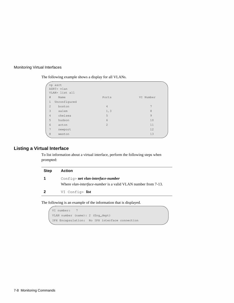
Monitoring Virtual Interfaces
7-8 Monitoring Commands
The following example shows a display for all VLANs.
Listing a Virtual InterfaceTo list information about a virtual interface, perform the following steps when prompted:
The following is an example of the information that is displayed.
Step Action
1 Config> net vlan-interface-number
Where vlan-interface-number is a valid VLAN number from 7-13.
2 VI Config> list
+p asrtASRT> vlanVLAN> list all
# Name Ports VI Number
1 Unconfigured
2 boston 4 7
3 salem 1,3 8
4 chelsea 5 9
5 hudson 6 10
6 acton 2 11
7 newport 12
8 weston 13
VI number: 7
VLAN number (name): 2 (Eng_dept)
IPX Encapsulation: No IPX interface connection
Removing the Module 8-1
Chapter 8
Removing the Module
Overview
IntroductionThis chapter describes how to remove the DECswitch 900EF Router from a DEChub 900 MultiSwitch. To remove the DECswitch 900EF Router from a standalone module, refer to the DEChub ONE Installation manual.
In this chapter
Topic Page
Removing the Cables 8-2
Unseating the Module 8-4

Removing the Cables
8-2 Removing the Module
Removing the Cables
WARNING
Some fiber optic equipment can emit laser or infrared light that can injure your eyes. Never look into an optical fiber or connector port. Always assume the cable is connected to a light source.
To remove cables from the module, complete the step in the following table that is appropriate for your type of cable (see Figure 8-1).
Step Action
1 FDDI cables, press the locking clips (1) on the cable plug, then pull out the cable.
2 AUI cables, push the connector slide latch up (2) to the unlocked position, then pull out the cable.
3 UTP/ScTP cables, press the release tab (3) on the cable plug, then pull out the cable.
4 Optical Bypass Relay (OBR) cables, refer to the removal instructions included with the OBR.

Removing the Module 8-3
Removing the Cables
Figure 8-1: Cable Removal
NPG-0109-95F
1
2
3
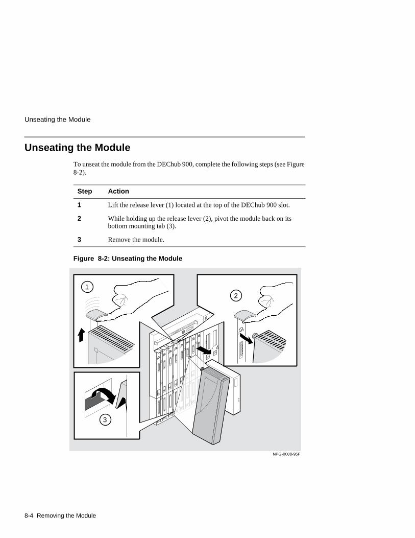
Unseating the Module
8-4 Removing the Module
Unseating the Module
To unseat the module from the DEChub 900, complete the following steps (see Figure 8-2).
Figure 8-2: Unseating the Module
Step Action
1 Lift the release lever (1) located at the top of the DEChub 900 slot.
2 While holding up the release lever (2), pivot the module back on its bottom mounting tab (3).
3 Remove the module.
NPG-0008-95F
2
3
1

Problem Solving A-1
Appendix A
Problem Solving
Overview
IntroductionThis appendix describes how to diagnose and solve problems with the module using the LED displays.
In this appendix
Topic Page
LED Descriptions A-2
Problem Solving Using LEDs A-4
LED Descriptions
A-2 Problem Solving
LED Descriptions
The module’s LEDs provide dynamic indications of the status of the module. The LEDs can be in various states (on, off, or flashing), and can change color (green or yellow) depending on the operational status of the module or the level of activity on the network.
Normal PowerupWhen power to the module is initially turned on, the following events occur:
Event Description
1 The module’s Power LED lights as soon as power is applied to the unit.
2 The module initiates its built-in self-test. Flashing Port State LEDs and activity LEDs indicate that the module is running various subroutines as part of the self-test.
3 After the successful completion of self-test (within 60 seconds after power is applied), the Module OK LED lights, and remains lit.
4 The remaining LEDs (Port State and Network Activity LEDs, and PHY LEDs) now indicate their operational status, as described in the following tables.
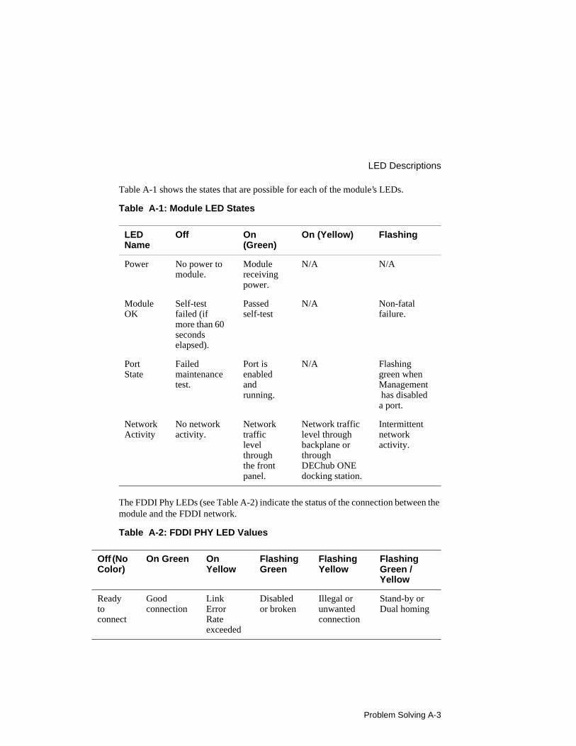
Problem Solving A-3
LED Descriptions
Table A-1 shows the states that are possible for each of the module’s LEDs.
Table A-1: Module LED States
The FDDI Phy LEDs (see Table A-2) indicate the status of the connection between the module and the FDDI network.
Table A-2: FDDI PHY LED Values
LED Name
Off On (Green)
On (Yellow) Flashing
Power No power to module.
Module receiving power.
N/A N/A
Module OK
Self-test failed (if more than 60 seconds elapsed).
Passed self-test
N/A Non-fatal failure.
Port State
Failed maintenance test.
Port is enabled and running.
N/A Flashing green when Management has disabled a port.
NetworkActivity
No network activity.
Network traffic level through the front panel.
Network traffic level through backplane or through DEChub ONE docking station.
Intermittent network activity.
Off (No Color)
On Green On Yellow
Flashing Green
FlashingYellow
Flashing Green / Yellow
Ready to connect
Good connection
Link Error Rate exceeded
Disabled or broken
Illegal or unwanted connection
Stand-by or Dual homing

Problem Solving Using LEDs
A-4 Problem Solving
Problem Solving Using LEDs
When diagnosing a problem with the module, note that the problem is often indicated by the combined states of the module’s LEDs. Table A-3 lists the typical combined states of the LEDs for various error conditions that can occur during initial installation of the device, along with probable causes and corrective actions to take.
Table A-3: Problem Solving Using LEDs
Symptom Probable Cause Corrective Action
Power LED is off. The module is not receiving +5Vdc.
Check the power status on the Hub Manager status display.
If the Hub Manager status display indicates that power is available for this module, press the release lever and reseat or remove the module.
Inspect the module's 48- or 160-pin connector for bent, broken, or dirty pins.
If the problem persists, either replace the module or contact your service representative to correct the problem.
Module OK LED is off.
Self-test in progress.
Wait for self-test to complete.
Self-test failed. If the LED does not light within 60 seconds, lift the release lever momentarily to repeat the self-test.
If self-test fails again, replace the module. If the problem persists, contact your service representative to correct the problem.
Module OK LED is off and Port State LED for Port 1 is blinking green (once every 8 seconds).
Module's firmware image is corrupted.
Either replace the module or contact your service representative to correct the problem.
Module OK LED is flashing, but module continues to operate normally.
A nonfatal error occurred.
Power off and on. If the problem persists, either replace the module or contact your service representative to correct the problem.
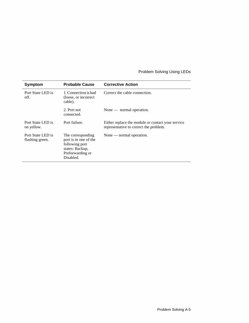
Problem Solving A-5
Problem Solving Using LEDs
Port State LED is off.
1. Connection is bad (loose, or incorrect cable).
Correct the cable connection.
2. Port not connected.
None — normal operation.
Port State LED is on yellow.
Port failure. Either replace the module or contact your service representative to correct the problem.
Port State LED is flashing green.
The corresponding port is in one of the following port states: Backup, Preforwarding or Disabled.
None — normal operation.
Symptom Probable Cause Corrective Action

Connector and Pin Assignments B-1
Appendix B
Connector and Pin Assignments
Overview
IntroductionThis appendix shows the pin assignments of the connectors, cables, and adapters that are part of, or can be used with, the module.
In This Chapter
Topic Page
Connector Assignments B-2
Internal and External Crossover Configurations B-7
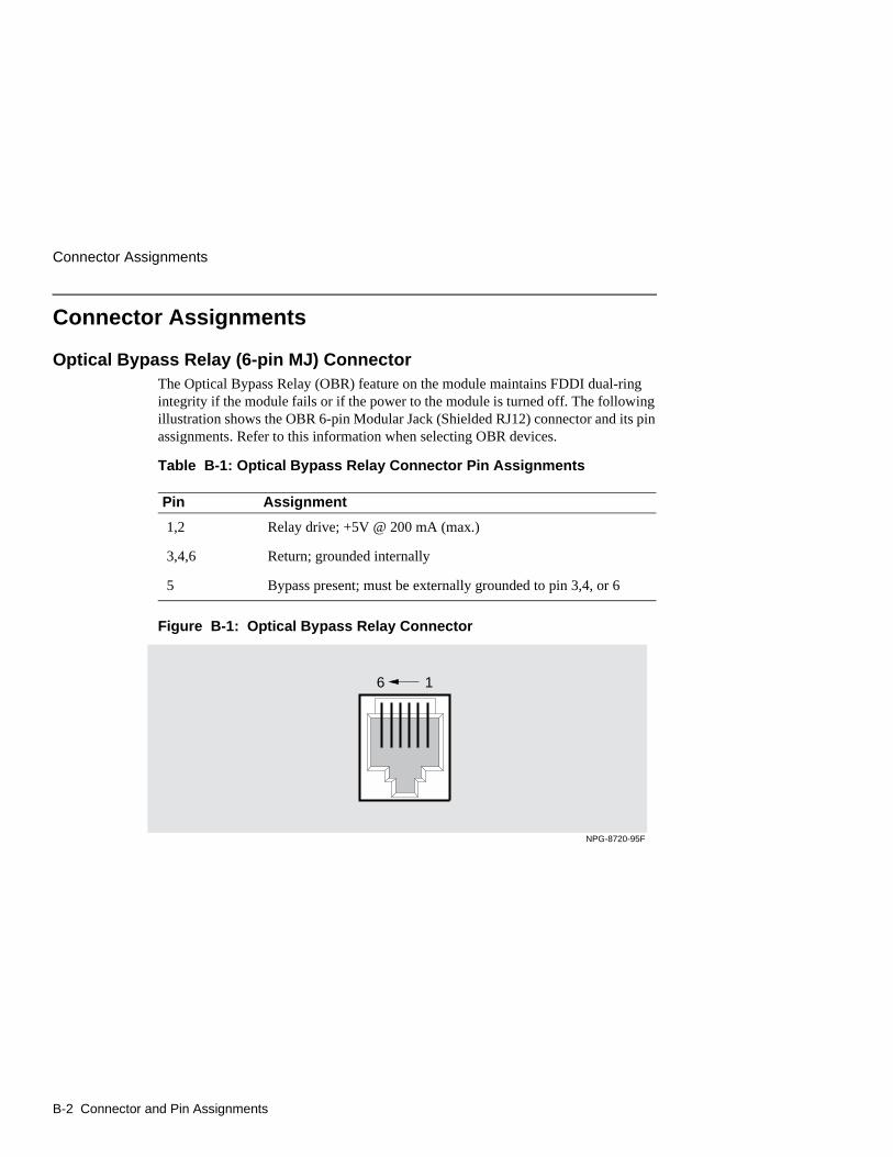
Connector Assignments
B-2 Connector and Pin Assignments
Connector Assignments
Optical Bypass Relay (6-pin MJ) ConnectorThe Optical Bypass Relay (OBR) feature on the module maintains FDDI dual-ring integrity if the module fails or if the power to the module is turned off. The following illustration shows the OBR 6-pin Modular Jack (Shielded RJ12) connector and its pin assignments. Refer to this information when selecting OBR devices.
Table B-1: Optical Bypass Relay Connector Pin Assignments
Figure B-1: Optical Bypass Relay Connector
Pin Assignment
1,2 Relay drive; +5V @ 200 mA (max.)
3,4,6 Return; grounded internally
5 Bypass present; must be externally grounded to pin 3,4, or 6
6
NPG-8720-95F
1
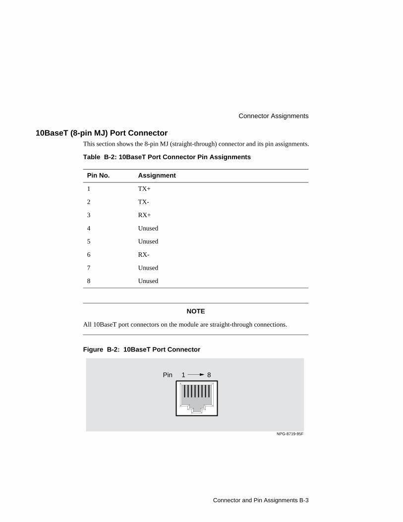
Connector and Pin Assignments B-3
Connector Assignments
10BaseT (8-pin MJ) Port ConnectorThis section shows the 8-pin MJ (straight-through) connector and its pin assignments.
Table B-2: 10BaseT Port Connector Pin Assignments
NOTE
All 10BaseT port connectors on the module are straight-through connections.
Figure B-2: 10BaseT Port Connector
Pin No. Assignment
1 TX+
2 TX-
3 RX+
4 Unused
5 Unused
6 RX-
7 Unused
8 Unused
NPG-8719-95F
Pin 1 8
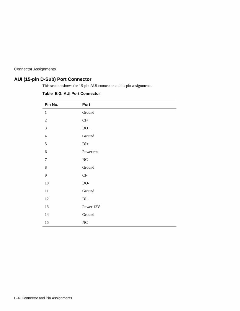
Connector Assignments
B-4 Connector and Pin Assignments
AUI (15-pin D-Sub) Port ConnectorThis section shows the 15-pin AUI connector and its pin assignments.
Table B-3: AUI Port Connector
Pin No. Port
1 Ground
2 CI+
3 DO+
4 Ground
5 DI+
6 Power rtn
7 NC
8 Ground
9 CI-
10 DO-
11 Ground
12 DI-
13 Power 12V
14 Ground
15 NC

Connector and Pin Assignments B-5
Connector Assignments
Figure B-3: AUI Port Connector
H8571-J AdapterThis section shows the H8571-J adapter (6-pin MMJ to 9-pin D-Sub connector) and its pin assignments.
Figure B-4: H8571-J Adapter
NPG-0222-95F
8 1
15 9
NPG-5342-95F
1234567820
123456
6MMJ
9D-Sub(F)
DCDSDRDDTRGNDDSRRTSCTSRI

Connector Assignments
B-6 Connector and Pin Assignments
H8575-A AdapterThis section shows the H8575-A adapter (6-pin MMJ connector to 25-pin D-Sub connector) and its pin assignments.
Figure B-5: H8575-A Adapter
NOTE
EOS/ESD protection devices are not shown in the illustration.
1234567820
NPG-8793-95F
25 D-Sub(F)
6 MMJ
H8575-A
123456
DTRTX+TX-RX-RX+DRS
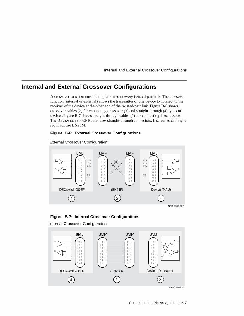
Connector and Pin Assignments B-7
Internal and External Crossover Configurations
Internal and External Crossover Configurations
A crossover function must be implemented in every twisted-pair link. The crossover function (internal or external) allows the transmitter of one device to connect to the receiver of the device at the other end of the twisted-pair link. Figure B-6 shows crossover cables (2) for connecting crossover (3) and straight-through (4) types of devices.Figure B-7 shows straight-through cables (1) for connecting these devices. The DECswitch 900EF Router uses straight-through connectors. If screened cabling is required, use BN26M.
Figure B-6: External Crossover Configurations
Figure B-7: Internal Crossover Configurations
(BN24F)
2 44
8MJ 8MJ8MP 8MP
External Crossover Configuration:
DECswitch 900EF Device (MAU)
12345678
TX+TX-RX+
RX-
12345678
12345678
TX+TX-RX+
RX-
12345678
T
R
T
R
NPB-0103-95F
12345678
12345678
NPG-0104-95F
4 1 3
8MJ 8MJ8MP 8MP
Internal Crossover Configuration:
(BN25G)DECswitch 900EF Device (Repeater)
T
R
T
R
12345678
12345678


Product Specifications C-1
Appendix C
Product Specifications
Overview
IntroductionThis appendix lists the operating specifications and the acoustical specifi-cations for the DECswitch 900EF Router.
In this chapter
Topic Page
Operating Specifications C-2
Connectors C-4
Acoustical Specifications C-5
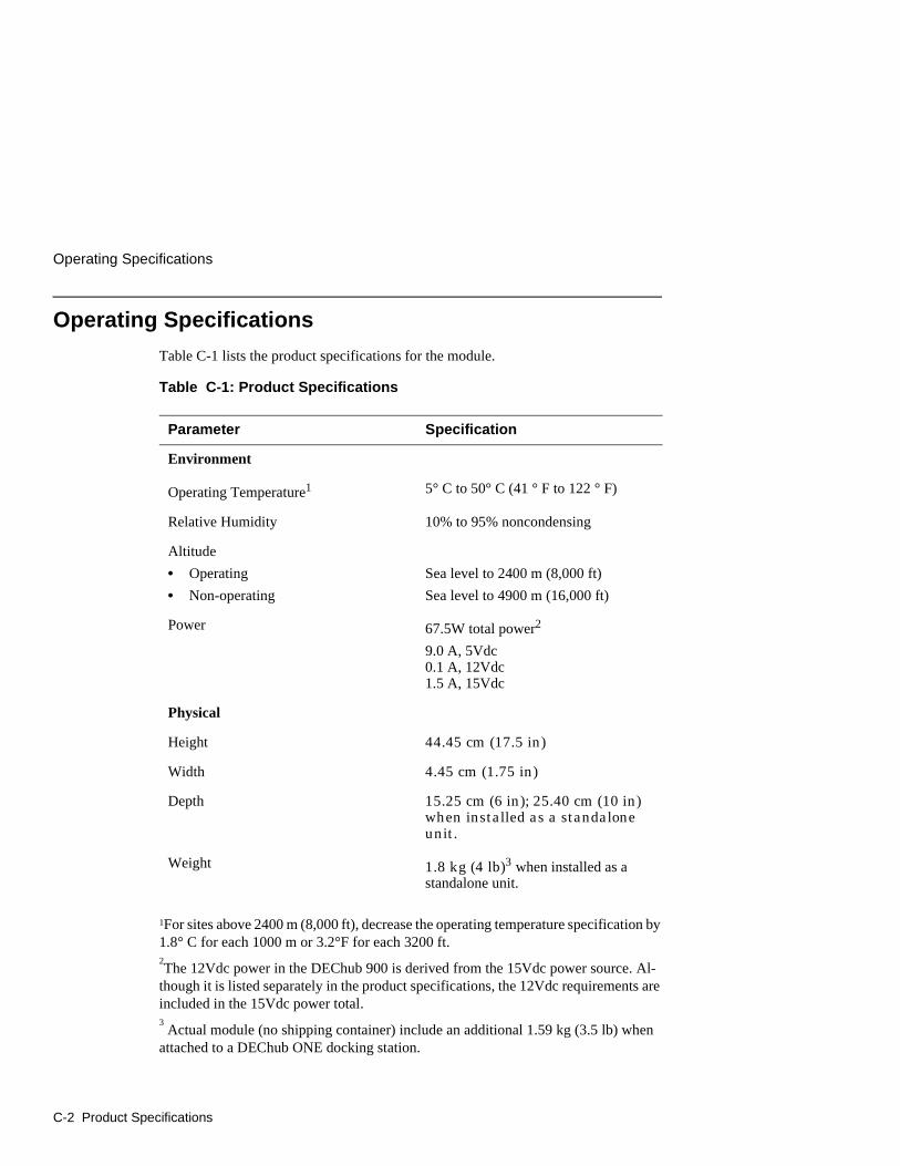
Operating Specifications
C-2 Product Specifications
Operating Specifications
Table C-1 lists the product specifications for the module.
Table C-1: Product Specifications
1For sites above 2400 m (8,000 ft), decrease the operating temperature specification by 1.8° C for each 1000 m or 3.2°F for each 3200 ft.2The 12Vdc power in the DEChub 900 is derived from the 15Vdc power source. Al-
though it is listed separately in the product specifications, the 12Vdc requirements are included in the 15Vdc power total.3 Actual module (no shipping container) include an additional 1.59 kg (3.5 lb) when
attached to a DEChub ONE docking station.
Parameter Specification
Environment
Operating Temperature1 5° C to 50° C (41 ° F to 122 ° F)
Relative Humidity 10% to 95% noncondensing
Altitude
• Operating
• Non-operating
Sea level to 2400 m (8,000 ft)
Sea level to 4900 m (16,000 ft)
Power 67.5W total power2
9.0 A, 5Vdc 0.1 A, 12Vdc1.5 A, 15Vdc
Physical
Height 44.45 cm (17.5 in)
Width 4.45 cm (1.75 in)
Depth 15.25 cm (6 in); 25.40 cm (10 in) when installed as a standalone unit.
Weight 1.8 kg (4 lb)3 when installed as a standalone unit.
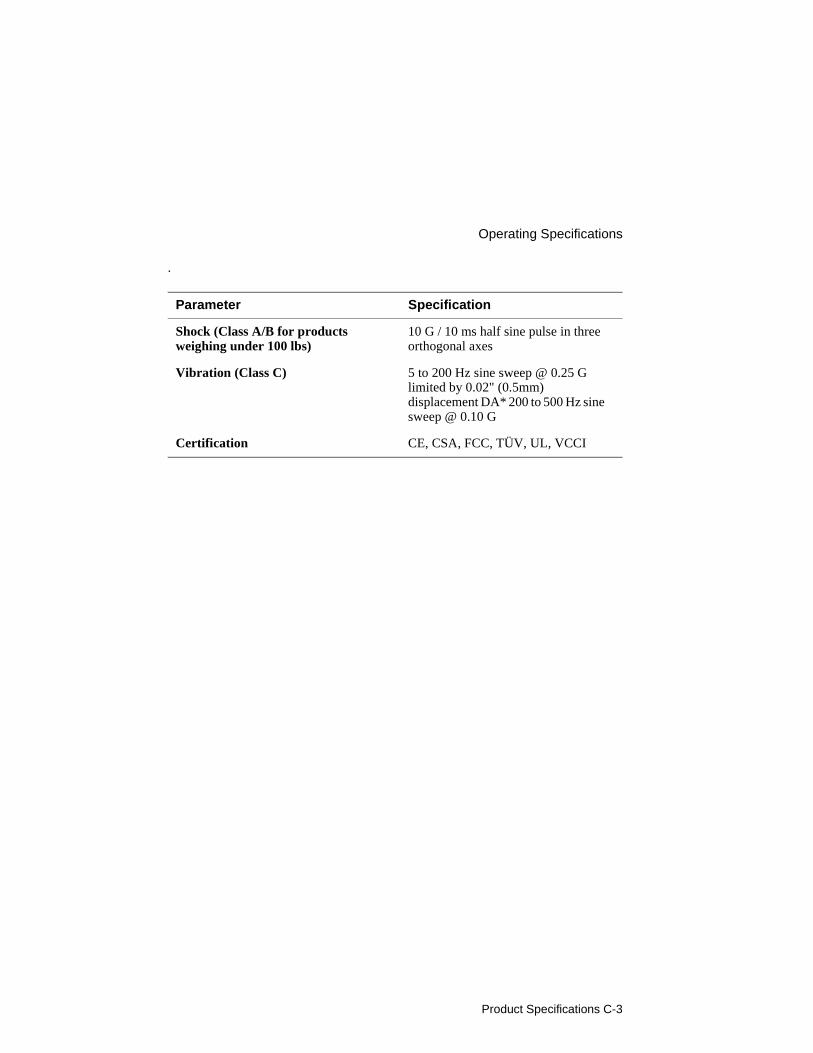
Product Specifications C-3
Operating Specifications
.
Parameter Specification
Shock (Class A/B for products weighing under 100 lbs)
10 G / 10 ms half sine pulse in three orthogonal axes
Vibration (Class C) 5 to 200 Hz sine sweep @ 0.25 G limited by 0.02" (0.5mm) displacement DA* 200 to 500 Hz sine sweep @ 0.10 G
Certification CE, CSA, FCC, TÜV, UL, VCCI
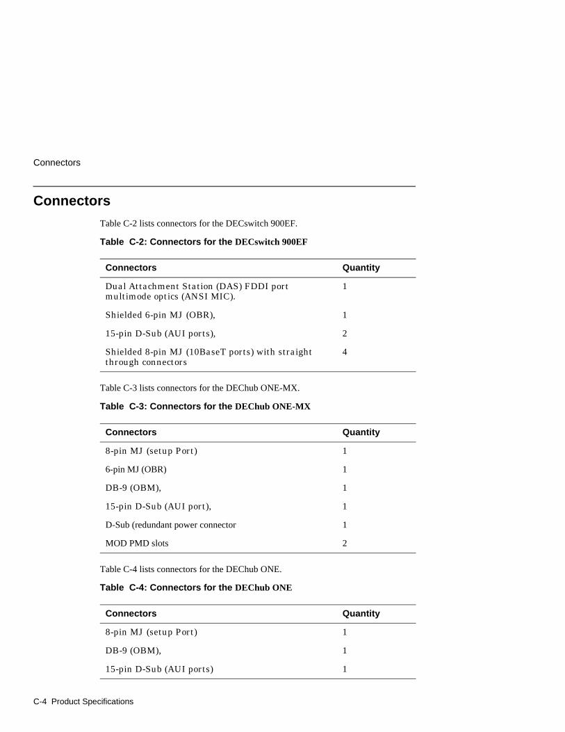
Connectors
C-4 Product Specifications
Connectors
Table C-2 lists connectors for the DECswitch 900EF.
Table C-2: Connectors for the DECswitch 900EF
Table C-3 lists connectors for the DEChub ONE-MX.
Table C-3: Connectors for the DEChub ONE-MX
Table C-4 lists connectors for the DEChub ONE.
Table C-4: Connectors for the DEChub ONE
Connectors Quantity
Dual Attachment Station (DAS) FDDI port multimode optics (ANSI MIC).
1
Shielded 6-pin MJ (OBR), 1
15-pin D-Sub (AUI ports), 2
Shielded 8-pin MJ (10BaseT ports) with straight through connectors
4
Connectors Quantity
8-pin MJ (setup Port) 1
6-pin MJ (OBR) 1
DB-9 (OBM), 1
15-pin D-Sub (AUI port), 1
D-Sub (redundant power connector 1
MOD PMD slots 2
Connectors Quantity
8-pin MJ (setup Port) 1
DB-9 (OBM), 1
15-pin D-Sub (AUI ports) 1
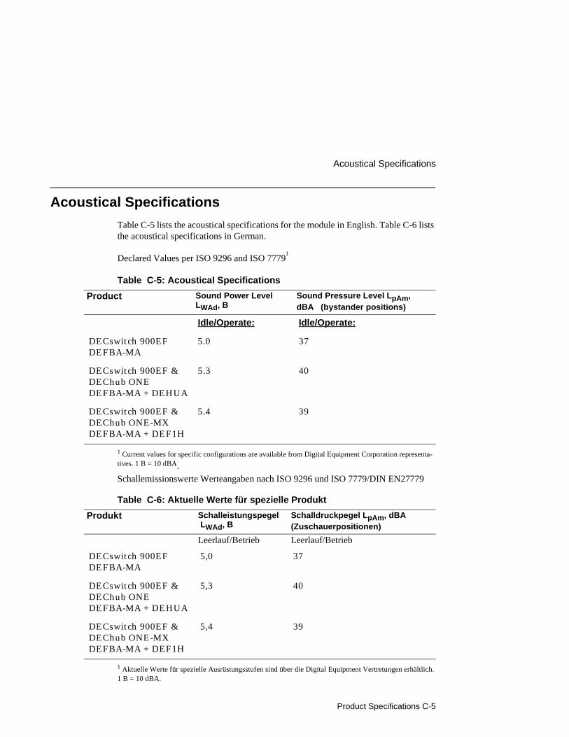
Product Specifications C-5
Acoustical Specifications
Acoustical Specifications
Table C-5 lists the acoustical specifications for the module in English. Table C-6 lists the acoustical specifications in German.
Declared Values per ISO 9296 and ISO 77791
Table C-5: Acoustical Specifications
1 Current values for specific configurations are available from Digital Equipment Corporation representa-tives. 1 B = 10 dBA.
Schallemissionswerte Werteangaben nach ISO 9296 und ISO 7779/DIN EN27779
Table C-6: Aktuelle Werte für spezielle Produkt
1 Aktuelle Werte für spezielle Ausrüstungsstufen sind über die Digital Equipment Vertretungen erhältlich. 1 B = 10 dBA.
Product Sound Power Level LWAd, B
Sound Pressure Level LpAm, dBA (bystander positions)
Idle/Operate: Idle/Operate:
DECswitch 900EF DEFBA-MA
5.0 37
DECswitch 900EF & DEChub ONE DEFBA-MA + DEHUA
5.3 40
DECswitch 900EF & DEChub ONE-MX DEFBA-MA + DEF1H
5.4 39
Produkt Schalleistungspegel LWAd, B
Schalldruckpegel LpAm, dBA (Zuschauerpositionen)
Leerlauf/Betrieb Leerlauf/Betrieb
DECswitch 900EF DEFBA-MA
5,0 37
DECswitch 900EF & DEChub ONE DEFBA-MA + DEHUA
5,3 40
DECswitch 900EF & DEChub ONE-MX DEFBA-MA + DEF1H
5,4 39

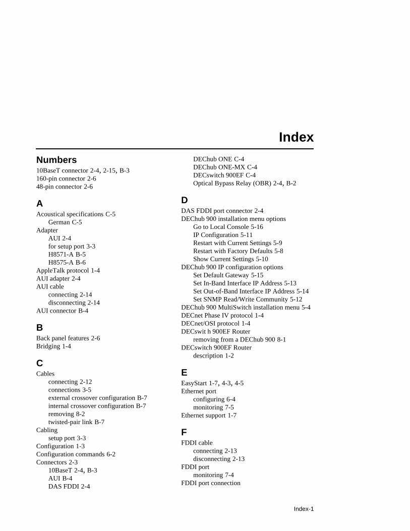
Index-1
Index
Numbers10BaseT connector 2-4, 2-15, B-3160-pin connector 2-648-pin connector 2-6
AAcoustical specifications C-5
German C-5Adapter
AUI 2-4for setup port 3-3H8571-A B-5H8575-A B-6
AppleTalk protocol 1-4AUI adapter 2-4AUI cable
connecting 2-14disconnecting 2-14
AUI connector B-4
BBack panel features 2-6Bridging 1-4
CCables
connecting 2-12connections 3-5external crossover configuration B-7internal crossover configuration B-7removing 8-2twisted-pair link B-7
Cablingsetup port 3-3
Configuration 1-3Configuration commands 6-2Connectors 2-3
10BaseT 2-4, B-3AUI B-4DAS FDDI 2-4
DEChub ONE C-4DEChub ONE-MX C-4DECswitch 900EF C-4Optical Bypass Relay (OBR) 2-4, B-2
DDAS FDDI port connector 2-4DEChub 900 installation menu options
Go to Local Console 5-16IP Configuration 5-11Restart with Current Settings 5-9Restart with Factory Defaults 5-8Show Current Settings 5-10
DEChub 900 IP configuration optionsSet Default Gateway 5-15Set In-Band Interface IP Address 5-13Set Out-of-Band Interface IP Address 5-14Set SNMP Read/Write Community 5-12
DEChub 900 MultiSwitch installation menu 5-4DECnet Phase IV protocol 1-4DECnet/OSI protocol 1-4DECswit h 900EF Router
removing from a DEChub 900 8-1DECswitch 900EF Router
description 1-2
EEasyStart 1-7, 4-3, 4-5Ethernet port
configuring 6-4monitoring 7-5
Ethernet support 1-7
FFDDI cable
connecting 2-13disconnecting 2-13
FDDI portmonitoring 7-4
FDDI port connection

Index-2
using commands to redirect 6-3FDDI support 1-7Features
bridging 1-4configuration 1-3EasyStart 1-7Ethernet support 1-7FDDI support 1-7hot swap 1-3management 1-3routing protocols 1-4SNMP support 1-6virtual LANs (VLANs) 1-5
Frame translation 1-7Front panel components 2-3
HH8571-A adapter B-5H8585-A adapter B-6Hot swap 1-3
IInstallation menu 4-3, 5-6Interfaces
listing 7-3IP address format 4-10IP protocols 1-4IPX protocol 1-4
specifying frame encapsulation type 6-11
LLEDs
displays A-2indicators 2-3problem solving with A-4states A-3troubleshooting A-4
MMAC addresses 2-3Management 1-3Menus
using for setting up 4-3, 5-6
Module components 2-3Module setup
using menus 4-3, 5-6Monitor mode
accessing 7-2exiting 7-2
OOBM
configuring 6-5Operating specifications
altitude C-2certification C-3humidity C-2power C-2shock C-3temperature C-2vibration C-3
Optical Bypass Relay (OBR) connector 2-4, B-2
PPacket translation 1-7Port switching 1-7Power ratings 2-9Product specifications C-2Protocols
AppleTalk 1-4DECnet Phase IV 1-4DECnet/OSI 1-4IP 1-4IPX 1-4
QQconfig 4-15Quick configuration 4-15
RRFCs
supported 1-6Routing protocols 1-4
SSetup port

Index-3
accessing 4-2, 5-2connecting 3-4
Setup port cabling 3-3Signaling standards 3-2SNMP support 1-6Specifications
acoustical C-5operating C-2
Standalone installation menu optionsConfigure IP 4-8Configure Out-of-Band Port 4-13Go to Local Console 4-15Out-of-Band Port Speed 4-14Restart with Current Settings 4-6Restart with Factory Defaults 4-5Show Current Settings 4-7
Standalone IP configuration optionsSet Default Gateway 4-12Set In-Band Interface IP Address 4-10Set Out-of-Band Interface IP Address 4-11Set SNMP Read/Write Community 4-9
UUTP/STP cable
connecting 2-15
VVirtual interface (VI)
listing 7-8Virtual interface (VI) number 6-7, 6-10, 7-8Virtual LAN (VLAN) number 6-7Virtual LANs (VLANs)
configuring 6-6create 6-7default 6-6, 6-9delete 6-8frame types 6-10IPX encapsulation 6-11list 6-9, 7-7modify 6-8monitoring 7-6name 6-8online help 6-7ports 6-8 to 6-9
support 1-5virtual interface (VI) number 6-7, 6-10, 7-8virtual LAN (VLAN) number 6-7