Embed Size (px)
Citation preview

1 5
1
Decommissioning Programmes DRAFT FOR CONSULTATION
Viking Satellites CD, DD, ED, GD, HD
& Associated Infield Pipelines

2 5
Document Control
Approvals
Name Signature Date
Prepared by Cathy Marston
Reviewed by Steven McColl
Approved by Ian McCulloch
Approved by Kate Simpson
Approved by Joe Farrell
Approved by Barry King
Revision Control
Rev Reference Changes / Comments Issue Date
1 COP-SNS-V-XX-X-PM-12-00001 Pre Draft for DECC 29-10-2014
2 COP-SNS-V-XX-X-PM-12-00001 Updated Pre Draft for DECC 19-12-2014
3 COP-SNS-V-XX-X-PM-12-00001 Updated Pre Draft for DECC 10-03-2015
4 COP-SNS-V-XX-X-PM-12-00001 Updated Pre Draft for DECC 01-05-2015
5 COP-SNS-V-XX-X-PM-12-00001 Draft for Consultation 16-09-2015
Distribution List
Name Company No of Copies
Ian McCulloch ConocoPhillips 1
Linda Harpley Britoil PLC / BP 1
3 5
Contents
INST = Installations; P/L = Pipelines INST P/L
CONTENTS 3 A. TABLE OF TERMS AND ABBREVIATIONS 4 B. TABLE OF FIGURES AND TABLES 5 C. TABLE OF APPENDICES 6 1. EXECUTIVE SUMMARY 7
1.1. COMBINED DECOMMISSIONING PROGRAMMES 7 1.2. REQUIREMENT FOR DECOMMISSIONING PROGRAMMES 7 1.3. INTRODUCTION 7 1.4. OVERVIEW OF INSTALLATIONS AND PIPELINES BEING DECOMMISSIONED 9 1.4.1. INSTALLATIONS 9 1.4.2. PIPELINES 9 1.5. SUMMARY OF PROPOSED DECOMMISSIONING PROGRAMMES 10 1.6. FIELD LOCATION INCLUDING FIELD LAYOUT AND ADJACENT FACILITIES 11 1.7. INDUSTRIAL IMPLICATIONS 15
2. DESCRIPTION OF ITEMS TO BE DECOMMISSIONED 16 2.1. SURFACE FACILITIES (TOPSIDES AND JACKETS) 16 2.2. SUBSEA INSTALLATIONS AND STABILISATION FEATURES 19 2.3. PIPELINES INCLUDING STABILISATION FEATURES 20 2.4. WELLS 23 2.5. DRILL CUTTINGS 24 2.6. INVENTORY ESTIMATES 24
3. REMOVAL AND DISPOSAL METHODS 26 3.1. TOPSIDES 26 3.1.1. TOPSIDES DESCRIPTIONS 26 3.1.2. REMOVAL METHODS 30 3.2. JACKETS 31 3.2.1. JACKET DECOMMISSIONING OVERVIEW 31 3.2.2. JACKET REMOVAL METHODS 34 3.3. SUBSEA INSTALLATIONS AND STABILISATION FEATURES 35 3.4. PIPELINES 35 3.4.1. DECOMMISSIONING OPTIONS 35 3.4.2. COMPARATIVE ASSESSMENT METHOD 36 3.5. PIPELINE STABILISATION FEATURES 37 3.6. WELLS 38 3.7. DRILL CUTTINGS 38 3.7.1. DRILL CUTTINGS DECOMMISSIONING OPTIONS: 38 3.8. WASTE STREAMS 39
4. ENVIRONMENTAL IMPACT ASSESSMENT 40 4.1. ENVIRONMENTAL SENSITIVITIES 40 4.2. POTENTIAL ENVIRONMENTAL IMPACTS AND THEIR MANAGEMENT 42 4.2.1. ENVIRONMENTAL IMPACT ASSESSMENT SUMMARY 42
5. INTERESTED PARTY CONSULTATIONS 46 6. PROGRAMME MANAGEMENT 47
6.1. PROJECT MANAGEMENT AND VERIFICATION 47 6.2. POST-DECOMMISSIONING DEBRIS CLEARANCE AND VERIFICATION 47 6.3. SCHEDULE 47 6.4. COSTS 48 6.5. CLOSE OUT 48 6.6. POST – DECOMMISSIONING MONITORING AND EVALUATION 48
7. SUPPORTING DOCUMENTS 48 8. PARTNER LETTERS OF SUPPORT 49

4 5
A. Table of Terms and Abbreviations
Abbreviation Explanation
AR Viking A Riser Platform
CA Comparative Assessment
CD Viking C Satellite Platform
CoP Cessation of Production
DD Viking D Satellite Platform
DECC Department of Energy and Climate Change
ED Viking E Satellite Platform
EIA Environmental Impact Assessment
EMS Environmental Management System
ES Environmental Statement
FD Viking F Satellite Platform
GD Viking G Satellite Platform
HD Viking H Satellite Platform
HLV Heavy Lift Vessel
KP Kilometre Point
KPI Key Performance Indicator
LAT Lowest Astronomical Tide
LOGGS Lincolnshire Offshore Gas Gathering System
MeOH Methanol
NORM Naturally Occurring Radioactive Material
NUI Normally Unattended Installation
OGUK Oil and Gas United Kingdom
P&A Plug and Abandon
PMT Project Management Team
PWA Pipeline Works Authorisation
SCI Site of Community Importance
SLV Shear Leg Vessel
SNS Southern North Sea
Te Tonne
TGT Theddlethorpe Gas Terminal
Tscf Trillion standard cubic foot
UKCS United Kingdom Continental Shelf

5 5
B. Table of Figures and Tables
Figure No Description Page
1.1 Viking Field Location in UKCS 11
1.2 Viking Field Layout 12
1.3 Adjacent Facilities 14
2.1.1 Photograph of Viking CD 16
2.1.2 Photograph of Viking DD 17
2.1.3 Photograph of Viking ED 17
2.1.4 Photograph of Viking GD 18
2.1.5 Photograph of Viking HD 18
3.1.1 CD Topsides 26
3.1.2 DD Topsides 27
3.1.3 ED Topsides 27
3.1.4 GD Topsides 28
3.1.5 HD Topsides 28
3.2.1 CD Jacket Elevation 31
3.2.2 DD Jacket Elevation 32
3.2.3 ED Jacket Elevation 32
3.2.4 GD Jacket Elevation 33
3.2.5 HD Jacket Elevation 33
6.1 Gantt Chart of Project Plan 47
Table No Description Page
1.1 Installations Being Decommissioned 9
1.2 Installation Section 29 Notice Holder Details 9
1.3 Pipelines Being Decommissioned 9
1.4 Pipeline Section 29 Notice Holder Details 9
1.5 Summary of Decommissioning Programmes 10
1.6 List of Adjacent Facilities 13
2.1 Surface Facilities Information 16
2.2 Subsea Installation and Stabilisation Features 19
2.3 Pipeline / Flowline / Umbilical Information 20
2.4 Subsea Pipeline Stabilisation Features 22
2.5 Well Information 23
2.6 Drill Cuttings Pile Information 24
2.7 Installation Material Functional Category Summary 24
2.8 Pipeline and Mattress Material Functional Category Summary 25
3.1 Cleaning of Topsides for Removal 29
3.2 Topsides Removal Methods 30
3.3 Jacket Removal Methods 34
3.4 Subsea Installations and Stabilisation features 35
3.5 Pipeline or Pipeline Groups / Decommissioning Options 35
3.6 Outcomes of Comparative Assessment 37
3.7 Pipeline Stabilisation Features 37
3.8 Well Plug and Abandonment 38
3.9 Waste Stream Management Methods 39
3.10 Inventory Disposition 39
4.1 Environmental Sensitivities 40
4.2 Environmental Impact Management 42
5.1 Summary of Stakeholder Comments 46
6.1 Provisional Decommissioning Programme Costs 48
7.1 Supporting Documents 48

6 5
C. Table of Appendices
Appendix No Description
None

7 5
1. Executive Summary
Combined Decommissioning Programmes 1.1
This document contains two decommissioning programmes for (1) 5 Viking Satellite installations and (2) for 10 interfield pipelines (5 pairs) for each set of associated notices served under Section 29 of the Petroleum Act 1998.
1.2 Requirement for Decommissioning Programmes
Installations: In accordance with the Petroleum Act 1998, ConocoPhillips (U.K.) Limited as Operator of the Viking Field and on behalf of the Section 29 notice holders (see Table 1.2 and Section 8) is applying to the Department of Energy and Climate Change to obtain approval for decommissioning of the Viking CD, DD, ED, GD and HD installations detailed in Section 2 of this document. Pipelines: In accordance with the Petroleum Act 1998, ConocoPhillips (U.K.) Limited as Operator of the Viking Field and on behalf of the Section 29 notice holders (see Table 1.4 and Section 8) is applying to the Department of Energy and Climate Change to obtain approval for decommissioning of the Viking CD, DD, ED, GD and HD interfield pipelines detailed in Section 2 of this document. In conjunction with public, stakeholder and regulatory consultation, the decommissioning programmes are submitted in compliance with national and international regulations and with consideration of DECC guidelines. The schedule outlined in this document is for a 4 year decommissioning project beginning June 2014, when the Ensco 92 Jack Up Drilling Rig commenced well Plug and Abandonment (P&A) activities at the Viking GD satellite platform.
Introduction 1.3
The Viking Field was discovered in 1965 and is spread over a 24 km diameter sector in blocks 49/11d, 49/12a, 49/16a, 49/16c, 49/17a, and 49/18a in the Southern North Sea, approximately 138 km due East of Theddlethorpe on the Lincolnshire coast. The reservoirs developed with wells from the Viking satellites covered by this document are in the following Quad/blocks:
Viking CD 49/17a,
Viking DD 49/17a/18a,
Viking ED 49/16a,
Viking GD 49/17a,
Viking HD 49/12a/17a.
Production from the Viking reservoirs commenced in 1972 from two manned multi jacket bridge linked complexes Viking A (Alpha) and Viking B (Bravo). Gas export from Viking A and B was combined at the Viking A Riser (AR) platform prior to being exported to the Theddlethorpe Gas Terminal (TGT) via a 28” export pipeline. Normally Unattended Installations (NUI) were subsequently tied back to the two manned complexes as follows:
1974 – 1975, Viking CD, DD, ED, GD, HD tied back to Viking B complex
1975 Viking FD tied back to Viking A complex
1984 Victor JD tied back to Viking B complex
8 5
1995 Victor JM (subsea) tied-back to Victor JD
1998 Viking KD and LD tied back to Viking B complex
2000 Vixen VM (subsea) tied back to Viking B complex
2008 Victoria SM (subsea) tied back to Viking B complex
In 1991 the reservoirs produced by the Viking A Complex and Viking FD satellite became uneconomic and were decommissioned in 1995. The Viking AR platform was r e designed as a Normally Unattended Installation (NUI) and transported export gas from the Viking B Complex to TGT until 2009. In 2009 Viking B export gas was rerouted to the Lincolnshire Offshore Gas Gathering System (LOGGS) manned Complex via a new 16” export pipeline. The 5 Viking satellites CD, DD, ED, GD, HD covered by these Decommissioning Programmes have produced 1.7 Tscf of gas and depending on the satellite; last produced between 2002 and 2012. Cessation of Production applications were submitted and approved as follows:
Field Reservoirs Installation Submission Date Approval Date
Viking D Field G GD 01 April 2011 15 April 2011
Viking E Field Gn GD 22 July 2015 19 August 2015
Viking B Field B, C, D BD, CD, DD 15 May 2014 18 June 2014
Viking A Field H HD 14 August 2014 20 August 2014
Viking C Field E ED 25 June 2015 14 August 2015
All 5 Viking Satellites are small installations with total combined Topsides and Jacket weights ranging from 750 Te to 1358 Te; stand in 22m to 32m of water and are tied back to the Viking B complex by individual buried pipelines ranging between 4km and 12km in length. The small size, shallow water depth and design life of the 5 Viking Satellites has determined the philosophy of their decommissioning, which will be to:
Well Plug and Abandon (P&A)
Remove the satellite platforms
Leave the cleaned pipelines in situ.
The other installations and pipelines in the Viking field will subsequently be decommissioned at an appropriate time and will be covered by their own Decommissioning Programmes.

9 5
Overview of Installations and Pipelines Being Decommissioned 1.4
1.4.1 Installations
Table 1.1 Installations Being Decommissioned
Field Names Quad / Block
Fields Viking A,B,C,D,E Production Type Gas / Condensate
Water Depth 22.6m – 32.3 m UKCS block Quad 49 Blocks
12a/16a/ 17a and 18a
Surface Installations
Number Type Topsides Weight (Te) Jacket Weight (Te)
5 Fixed steel jacket 1080 4021
Subsea Installations Number of Wells
Number Type Number Type
0 N/A 15 Platform
Drill Cuttings Piles Distance to Median Distance from nearest
UK coastline
Number of Piles Total Est volume m3 km km
0 0 Viking DD 18 km Viking ED 78 km
See Figure 1.1 for further details.
Table 1.2 Installation Section 29 Notice Holders Details
Section 29 Notice Holders Registration Number Equity Interest
ConocoPhillips (U.K.) Limited 00524868 50%
ConocoPhillips Petroleum Limited 01247477 0%
Britoil Limited SC077750 50%
1.4.2 Pipelines
Table 1.3 Pipelines Being Decommissioned
Number of Pipelines 10 See table 2.3
Table 1.4 Pipelines Section 29 Notice Holders Details
Section 29 Notice Holders Registration Number Equity Interest
ConocoPhillips (U.K.) Limited 00524868 50%
Britoil Limited SC077750 50%

10
5
1.5 Summary of Proposed Decommissioning Programmes
Table 1.5: Summary of Decommissioning Programmes
Selected Option Reason for Selection Proposed Decommissioning Solution
1. Topsides
Complete removal, dismantlement and reuse/ recycling and disposal.
Topsides past design life, equipment obsolete and degraded, or recovery no longer economic.
Removed wholly by Heavy Lift Vessel (HLV) transported to appropriate land based facility for dismantlement, recycling and disposal. Equipment that cannot be re-used will be recycled or disposed of as appropriate.
2. Jackets
Complete removal (3m below seabed), dismantlement and reuse/recycling and disposal.
Meets DECC regulatory requirements. Jackets past design life.
Removed by HLV, transported to appropriate land based facility for dismantlement, recycling and disposal.
3.Subsea Installations
Not Applicable Not Applicable Not Applicable
4. Pipelines, Flowlines and Umbilicals
Pipelines will be flushed and decommissioned in situ. Concrete mattresses and other pipeline stabilisation structures will be decommissioned in situ.
In situ decommissioning with minimum intervention option: All mattresses would be left in situ to maintain pipeline stabilisation. Minimise disturbance of the established environment. Reduce the requirement for the introduction of new material (Rock Dump) to the Site of Community Importance (SCI).
Pipelines will be flushed prior to subsea disconnection from the Satellite. Pipelines would be left open and flooded with seawater with cut ends only to be rock dumped as required. Post flushing, the remaining pipeline would be left in its current state, marked on sea charts and notifications issued to fishermen/other users of the sea. Concrete mattresses and other pipeline stabilisation structures will be decommissioned in situ.
5.Well Abandonment Operations
Permanent well Plug and Abandonment (P&A).
Meets DECC regulatory requirements.
Abandonment in accordance with Oil and Gas UK Guidelines for the Suspension and Abandonment of Wells.

11
5
Table 1.5: Summary of Decommissioning Programmes (cont.)
Selected Option Reason for Selection Proposed Decommissioning Solution
6. Drill Cuttings
None required. No Drill Cuttings Piles have been identified by seabed survey.
None required.
7. Interdependencies
Platform removal can only occur after Well P&A and Topsides / Pipeline cleaning.
1.6 Field Location including Field Layout and Adjacent Facilities
Figure 1.1 – Viking Field Location in UKCS

12
5
The Viking development is part of the ConocoPhillips Southern North Sea (SNS) Gas Operation with the installations and pipelines covered by this decommissioning programme highlighted in the Field Layout Figure 1.2.
Figure 1.2 – Viking Field Layout
Facilities adjacent to the Viking Satellites that are potentially impacted by this decommissioning programme are listed below in Table 1.6 and highlighted in Figure 1.3.

13
5
Table 1.6 List of Adjacent Facilities
Owner Name Type Distance / Direction
Information Status
ConocoPhillips / BP
Viking Bravo Complex
Manned 4 Jacket bridge linked complex
CD to BD 4km DD to BD 4km ED to BD 12 km GD to BD 5km HD to BD 6 km
Each of the 10 pipelines to be decommissioned interconnects to the Viking BD Platform.
Operational
ConocoPhillips / BP
PL2643 16” Gas Pipeline
Viking BP to LOGGS
Crosses over PL91 & PL92
Operational
ConocoPhillips / BP
PL2644 3” MeoH Pipeline
LOGGS to Viking BP
Piggy backed onto PL2643. Crosses over PL91 & PL92
Operational
ConocoPhillips / BP
PL1767 10” Gas Pipeline
Vixen VM to Viking BD
Crosses over PL89 Operational
ConocoPhillips / BP
PL1768 Control Umbilical
Viking BD to Vixen VM
Crosses over PL89 Operational
Verus Petroleum
PL2526 6” Gas Pipeline
Victoria SM to Viking BD
Crosses over PL90 & PL93
Operational
Verus Petroleum
PLU2527 Umbilical Viking BD to Victoria SM
Crosses over PL90 & PL93
Operational
Impacts of Decommissioning Proposals
No anticipated impact on adjacent facilities if pipelines are decommissioned in situ.

14
5
Figure 1.3 - Adjacent Facilities (highlighted in yellow)

15
5
1.7 Industrial Implications
Principles of the contracting and procurement strategies to be utilised by ConocoPhillips as operator and on behalf of the other Section 29 notice holders, for the decommissioning of the Viking Satellites are listed below: 1. Publish project information and contact details on the DECC website:
www.gov.uk/oil-and-gas-projectpathfinder
2. ConocoPhillips participated in the PILOT Share Fair event in November 2014 providing
one to one sessions with the UK supply chain on the SNS decommissioning programme
and timeline.
3. ConocoPhillips decommissioning representatives attended the Energy Industry Council
CONNECT event held in Manchester November 2014 and provided one to one sessions
for EIC members.
4. The First Point Assessment (FPAL) database is the primary source for establishing
tender lists for contracts / purchases valued at US $ 100,000 and above, although it is
also used under this limit.
5. ConocoPhillips is committed to competitively bidding all of its major contracts where
possible and practicable. We are supporters of the UK Supply Chain Code of Practice
and our performance in this regard has been acknowledged through Excellence Awards
from Oil & Gas UK.

16
5
2. Description of Items to be Decommissioned
Surface Facilities (Topsides and Jackets) 2.1
Table 2.1 Surface Facilities Information
Name Facility Type
Location Topsides / Facilities
Jacket (if applicable)
WGS84 Format
Weight (Te)*
No of modules
Weight (Te)**
No of Legs
No of piles
Weight of piles (Te)
Viking CD
Fixed steel jacket
53° 25.396'N 02° 22.524'E
172 1 1185 10 12 62.4
below mudline
Viking DD
Fixed steel jacket
53° 26.469'N 02° 23.630'E
171 1 756 4 8 15.5
below mudline
Viking ED
Fixed steel jacket
53° 25.986'N 02° 09.191'E
409 1 752 4 8 15.5
below mudline
Viking GD
Fixed steel jacket
53° 26.851'N 02° 15.291'E
164 1 586 4 6 15.5
below mudline
Viking HD
Fixed steel jacket
53° 29.797'N 02° 19.464'E
164 1 743 4 8 15.5
below mudline
Note* Weights are based on structural designs and review of the Return to Scene (R2S) footage
Note** Weights are based on design drawings, include piles to mudline, (excludes marine growth)
Figure 2.1.1 Photograph of Viking CD

17
5
Figure 2.1.2 Photograph of Viking DD
Figure 2.1.3 Photograph of Viking ED

18
5
Figure 2.1.4 Photograph of Viking GD
Figure 2.1.5 Photograph of Viking HD

19
5
2.2 Subsea Installations and Stabilisation Features
Table 2.2 Subsea Installation and Stabilisation Features
Subsea installations and stabilisation features
Number Size / Weight (Te) Locations Comments / Status
Wellheads 0 0 None None present
Manifolds 0 0 None None present
Templates 0 0 None None present
Protection frames 0 0 None None present
SSIV 0 0 None None present
Concrete mattresses 0 0 None None present
Grout bags 0 0 None None present
Formwork 0 0 None None present
Frond mats 0 0 None None present
Rock dump 0 0 None None present
Other 0 0 None None present

2.3 Pipelines Including Stabilisation Features
Table 2.3 Pipeline / Flowline / Umbilical Information
Description Pipeline No
(as per PWA) Diameter (inches)
Length (km)
Description of Component Parts
Product Conveyed
From – To End Points
Burial Status Pipeline Status
Current Content
Gas Pipeline
PL89 12 4.023 Steel with concrete
and coal tar coatings
Gas, Condensate,
produced water,
Viking CD to Viking BD
Trenched & Buried, 64m exposed*,
no reportable spans** Out of use
Gas, Condensate, produced water
Gas Pipeline
PL90 12 4.148 Steel with concrete
and coal tar coatings
Gas, Condensate,
produced water,
Viking DD to Viking BD
Trenched & Buried, 16m exposed*,
no reportable spans** Out of use
Gas, Condensate, produced water,
MeOH, Corrosion Inhibitor
Gas Pipeline
PL91 12 12.875 Steel with concrete
and coal tar coatings
Gas, Condensate,
produced water,
Viking ED to Viking BD
Trenched & Buried, 3,893m exposed*,
no reportable spans** Operational
Gas, Condensate, produced water
Gas Pipeline
PL92 12 5.100 Steel with concrete
and coal tar coatings
Gas, Condensate,
produced water,
Viking GD to Viking BD
Trenched & Buried, 133m exposed*,
no reportable spans** Out of use
Gas, Condensate, produced water, MeOH, Corrosion
Inhibitor
Gas Pipeline
PL93 12 5.592 Steel with concrete
and coal tar coatings
Gas, Condensate,
produced water,
Viking HD to Viking BD
Trenched & Buried, 639m exposed*,
no reportable spans** Out of use
Gas, Condensate, produced water
Note * As per pipeline survey length Note ** As per FishSAFE requirements
20

Table 2.3 Pipeline / Flowline / Umbilical Information (cont.)
Description Pipeline No (as per PWA)
Diameter (inches)
Length (km)
Description of Component Parts
Product Conveyed
From – To End Points
Burial Status
Pipeline Status
Current Content
MeOH Pipeline Piggy backed onto PL89
PL132 2 4.023 Steel with
Polyethylene wrap
MeOH, corrosion inhibitor
Viking BD to Viking CD
Trenched & Buried, 64m exposed*, no reportable
spans**
Out of use MeOH, Corrosion
Inhibitor
MeOH Pipeline Piggy backed onto PL90
PL131 2 4.148 Steel with
Polyethylene wrap
MeOH, corrosion inhibitor
Viking BD to Viking DD
Trenched & Buried, 16m exposed*, no reportable
spans**
Out of use MeOH, Corrosion
Inhibitor
MeOH Pipeline Piggy backed onto PL91
PL133 2 12.875 Steel with
Polyethylene wrap
MeOH, corrosion inhibitor
Viking BD to Viking ED
Trenched & Buried, 3,893m exposed*,
no reportable spans**
Operational MeOH, Corrosion
Inhibitor
MeOH Pipeline Piggy backed onto PL92
PL66 2 5.100 Steel with
Polyethylene wrap
MeOH, corrosion inhibitor
Viking BD to Viking GD
Trenched & Buried, 133m exposed*,
no reportable spans**
Out of use MeOH, Corrosion
Inhibitor
MeOH Pipeline Piggy backed onto PL93
PL130 2 5.592 Steel with
Polyethylene wrap
MeOH, corrosion inhibitor
Viking BD to Viking HD
Trenched & Buried, 639m exposed*,
no reportable spans**
Out of use MeOH, Corrosion
Inhibitor
Note * As per pipeline survey length Note ** As per FishSAFE requirements
21

Table 2.4 Subsea Pipeline Stabilisation Features
Stabilisation Feature
Total Number*
Weight (Te)*
Locations** Exposed / Buried / Condition
Concrete mattresses
5 10 10 3
30 60 60 18
PL89 & PL132 at KP 0.002 PL90 & PL131 at KP 0.013 PL91 & PL133 at KP 0.025 and 10.807 PL93 & PL130 at KP 0.004
Exposed during 2006, 2007, 2008, 2009, 2011, 2012 surveys Exposed during 2009, 2011 surveys Exposed during 2007, 2009, 2011 surveys Exposed during 2009, 2011 surveys
Grout bags
0.4m length 3m length
13m length 8m length
PL90 & PL131 at KP 0.010 PL91 & PL133 at KP 0.029 PL92 & PL66 at KP 0.004 PL93 & PL130 at KP -0.032
Exposed during 2007, 2009, 2011 surveys Exposed during 2007 survey Exposed during 2007, 2009, 2011 surveys Exposed during 2007, 2009, 2011 surveys
Formwork None
Frond mats 1 1
6 6
PL89 & PL132 at KP 0.016 PL91 & PL133 at KP 11.936
Exposed during 2009 survey Exposed during 2008 survey
Rock Dump 9m section
49m section 46m section
PL89 & PL132 at KP 3.876 PL91 & PL133at KP 0.100 PL92 & PL66 at KP 0.044
Exposed during 2008 survey Exposed during 2009, 2011 surveys Exposed during 2009, 2011 surveys
Other
Note * The total number and weight for Mattresses have been estimated from the visual survey data and based on a typical mattress size of 6m by 3m and weight of 6 Te. Grout bag and Rock Dump have also been estimated from visual survey data. Note ** KP 0.00 is at the Viking BD end of the pipeline
22

23 5
2.4 Wells
Table 2.5 Well Information
Platform Wells Designation Status Category of Well
GB_049_17_C01 Gas Production Shut-in PL 3-3-3
GB_049_17_C02Z Gas Production Shut-in PL 3-3-3
GB_049_17_C03 Gas Production Suspended PL 3-3-3
GB_049_17_C04 Gas Production Shut-in PL 3-3-3
GB_049_17_D01 Gas Production Shut-in PL 3-3-4
GB_049_17_D02 Gas Production Shut-in PL 3-3-3
GB_049_16_E03A Gas Production Shut-in PL 3-3-3
GB_049_16_E04 Gas Production Shut-in PL 3-3-3
GB_049_16_E05 Gas Production Shut-in PL 3-3-3
GB_049_17_G01 Gas Production Suspended PL 3-3-3
GB_049_17_G04 Gas Production Shut-in PL 3-3-3
GB_049_17_G05 Gas Production Shut-in PL 3-3-3
GB_049_17_05Z Gas Production Suspended PL 4-4-4
GB_049_17_H02 Gas Production Shut-in PL 3-3-3
GB_049_17_H03 Gas Production Shut-in PL 3-3-3
Subsea Wells Designation Status Category of Well
0 Not Applicable N/A Not Applicable
Note: Status of wells prior to commencement of P&A campaign June 2014
For further details of well categorisation see OGUK guidelines for the Suspension or Abandonment of Wells –Issue 4 –July 2012.

24 5
2.5 Drill Cuttings
Table 2.6 Drill Cuttings Pile Information
Location of Pile Centre (Latitude / Longitude)
Seabed area (m2)
Estimated volume of cuttings (m3)
None of the facilities has a cuttings pile present
0 0
A 2013 Fugro survey (Fugro 2013c) found no evidence of cuttings piles from around the 5 Viking Satellites covered by these decommissioning programmes. The dynamic marine environment has resulted in the redistribution of drill cuttings.
2.6 Inventory Estimates
Table 2.7 Current Installation Material Functional Category Summary
Installation
Haz Mat / NORM
Te
Concrete
Te
Ferrous Metal
Te
Non-Ferrous Metal
Te
Plastics
Te
Other Non-Haz
Te*
Total
Te
Viking CD 15 0 1334 0 0.25 10 1359
Viking DD 15 0 905 0 0.25 8 928
Viking ED 28 0 1035 0 0 100 1163
Viking GD 14 0 727 0 0.25 8 749
Viking HD 15 0 885 0 0.25 8 908
Total 87 0 4886 0 1 134 5108
Note* Weights exclude the calculated 142Te marine growth associated with all assets

25 5
Table 2.8 Pipeline and Mattress Material Functional Category Summary
Installation
Description Haz Mat / NORM
Te
Concrete
Te
Ferrous Metal
Te
Non-Ferrous Metal
Te
Plastics
Te
Other Non-Haz
Te*
PL66 BD to GD
MeOH piggy back
0 0 38 0 2 0
PL89 CD to BD
Gas 40 253 425 0 0 0
PL90 DD to BD
Gas 42 266 447 0 0 0
PL91 ED to BD
Gas 120 778 1307 0 0 0
PL92 GD to BD
Gas 51 330 556 0 0 0
PL93 HD to BD
Gas 56 362 610 0 0 0
PL130 BD to HD
MeOH piggy back
0 0 42 0 2 0
PL131 BD to DD
MeOH piggy back
0 0 31 0 1 0
PL132 BD to CD
MeOH piggy back
0 0 29 0 1 0
PL133 BD to ED
MeOH piggy back
0 0 90 0 4 0
Mattresses - 0 168 0 0 0 0
Total 309 2157 3575 0 10 0
Note* Weights exclude the calculated 142Te marine growth associated with all assets

26 5
3. Removal and Disposal Methods
In line with the waste hierarchy, the re-use of an installation (or parts thereof) is first in the order of preferred decommissioning options considered. Options considered for re-use of the Viking Satellites were:
Further Hydrocarbon production from development local to the satellites
Relocation elsewhere to produce hydrocarbons
Sale for reuse to others
No economic or technical hydrocarbon developments local to any of the Viking Satellites were identified. The 5 Viking Satellites are past their design life, require refurbishment; contain obsolete control systems and components all of which makes their re-use uneconomic and therefore non-viable. The selected option for the 5 Viking Satellites CD, DD, ED, GD, HD is to remove, dismantle and dispose of them, ensuring a high level of material recycling.
3.1 Topsides
3.1.1 Topsides Descriptions
Viking CD The Viking CD topsides are a minimal facility designed for use as a NUI which extends 22.6m above Lowest Astronomical Tide (LAT). The Topsides weigh 172Te have a deck size of 12.2m by 8.5m and comprise of a wellbay, local equipment room, diesel power generation, pedestal crane and Helideck.
Figure 3.1.1 CD Topsides

27 5
Viking DD The Viking DD topsides are a minimal facility designed for use as a NUI which extends 22.6m above LAT. The Topsides weigh 171Te have a deck size of 12.2m by 8.6m and comprise of a wellbay, local equipment room, diesel power generation, pedestal crane and Helideck.
Figure 3.1.2 DD Topsides
Viking ED The Viking ED topsides are a minimal facility designed for use as a NUI which extends 29.5m above LAT. The Topsides weigh 409Te have a deck size of 20.0m by 16.5m and comprise of a wellbay, test separator, gas driven compressor, local equipment room, gas power generation, pedestal crane and Helideck.
Figure 3.1.3 ED Topsides

28 5
Viking GD The Viking GD topsides are a minimal facility designed for use as a NUI which extends 22.6m above LAT. The Topsides weigh 164 Te have a deck size of 12.2m by 8.8m and comprise of a wellbay, local equipment room, diesel power generation, pedestal crane and Helideck.
Figure 3.1.4 GD Topsides
Viking HD The Viking HD topsides are a minimal facility designed for use as a NUI which extends 23.2m above LAT. The Topsides weigh 164Te have a deck size of 12.2m by 8.9m and comprise of a wellbay, local equipment room, diesel power generation, pedestal crane and Helideck.
Figure 3.1.5 HD Topsides

29 5
Preparation / Cleaning: Table 3.1 describes the methods that will be used to flush, purge and clean the topsides offshore, prior to removal to shore.
Table 3.1 Cleaning of Topsides for Removal
Waste Type Composition of Waste Disposal Route
Hydrocarbons Process fluids Will be flushed, Nitrogen purged and vented
Produced solids Sand, NORM
Produced solids will be removed and disposed of during the dismantlement of the Topsides onshore.
Diesel Bunkered Diesel fuel
Bunkered Diesel will be drained and returned onshore for re-use or disposal.
Lubricating oils Lubricants for equipment e.g. gearboxes, pumps, pedestal crane compressor skid
Lubricating oils will be drained and returned onshore for re-use or disposal.

30 5
3.1.2 Removal Methods
Given the small size and combined weight of the Viking Satellites Topsides and Jackets, there is potential to remove both together in a single lift. The exception to this is ED which has a larger and heavier topsides, where it is likely that the topsides may be separated from the Jacket and two lifts carried out and CD where the 2 Jacket tripod support frames will have to be removed prior to the Topsides and Jacket being removed in a single lift.
Table 3.2 Topsides Removal Methods
1) HLV (semi-submersible crane vessel ) 2) Monohull crane vessel 3) SLV
4) Piece small 5) Other Simultaneous removal of Topsides with Jacket
Methods Considered Description
Single lift removal complete with Jacket by HLV / Monohull crane vessel / SLV
Removal of Topsides complete with Jacket in a single lift and transportation to shore for dismantlement, disposal and recycling.
Modular lift removal of Topsides by HLV / Monohull crane vessel / SLV
Removal of Topsides for transportation to shore for dismantlement, disposal and recycling.
Offshore removal “piece small” for onshore disposal
Removal of Topsides and dismantlement offshore for transportation onshore for disposal and recycling.
Proposed removal method and disposal route.
Removal of Topsides complete with Jacket in a single lift for CD,DD,GD,HD. Modular lift for ED Topsides. Transportation to shore for dismantlement, disposal and recycling. Trans-frontier shipment of waste will be addressed during the commercial tendering process.
Note:Option Considered in Comparative Assessment
31 5
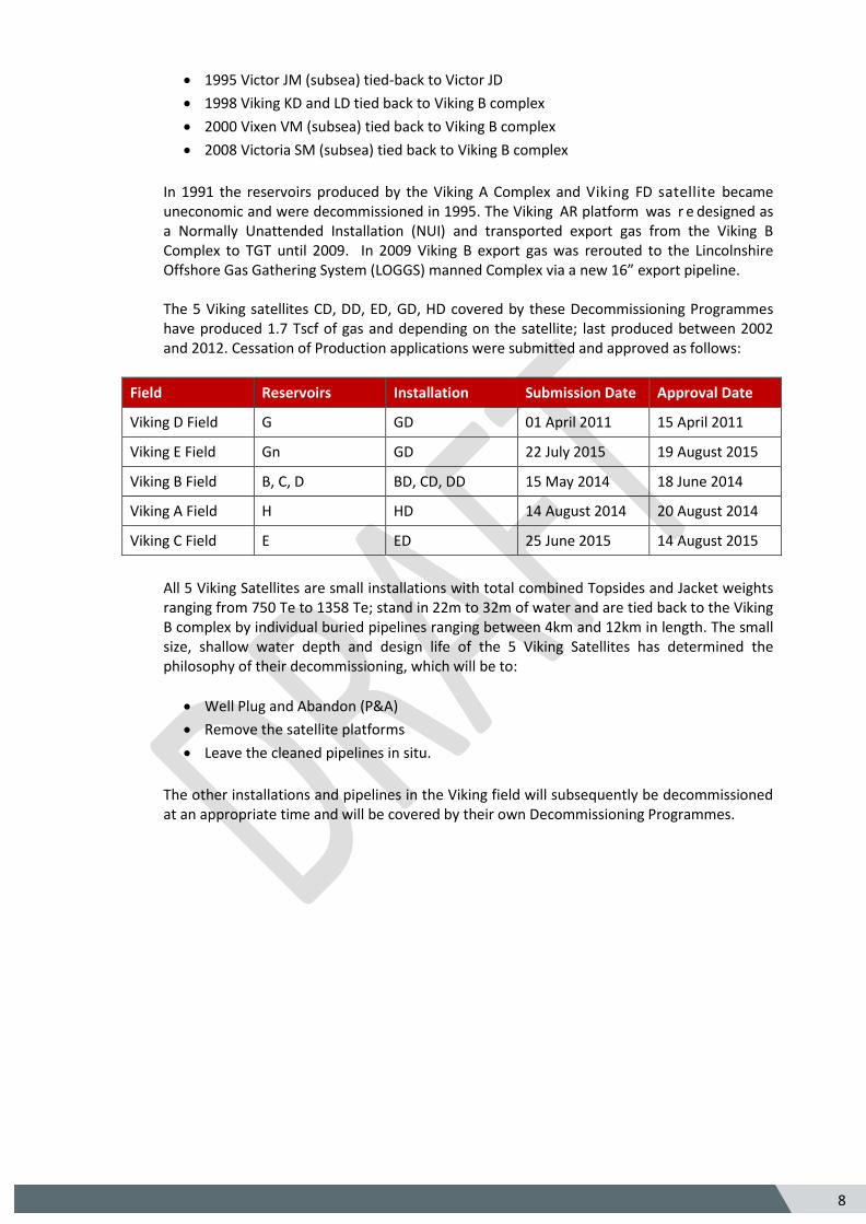
3.2 Jackets
The jackets of all five Viking Satellites are of the same basic design with the following differences:
The Jackets for Viking CD & GD were identical up until 1983 when the 2 Jacket tripod
support frames where added to the Viking CD Jacket.
The Jackets for Viking DD, ED and HD were designed with 2 extra piles to account for
greater water depth.
3.2.1 Jacket Decommissioning Overview
All Jackets will be removed to 3m below the seabed. As stated in section 3.1, given the small size of the Viking Satellites the Jackets except for ED will be removed in a single lift with the Topsides.
Figure 3.2.1 CD Jacket Elevation
18 18

32 5
Figure 3.2.2 DD Jacket Elevation
Figure 3.2.3 ED Jacket Elevation

33 5
F
Figure 3.2.4 GD Jacket Elevation
Figure 3.2.5 HD Jacket Elevation
34 5
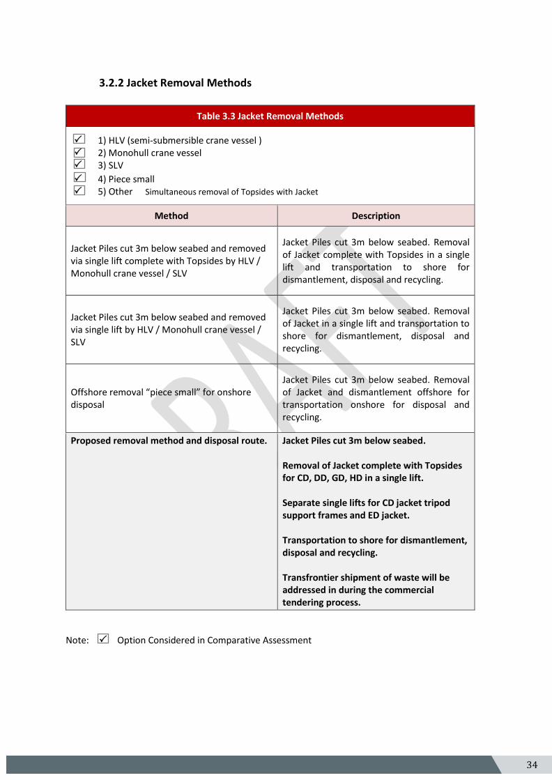
3.2.2 Jacket Removal Methods
Table 3.3 Jacket Removal Methods
1) HLV (semi-submersible crane vessel ) 2) Monohull crane vessel 3) SLV
4) Piece small 5) Other Simultaneous removal of Topsides with Jacket
Method Description
Jacket Piles cut 3m below seabed and removed via single lift complete with Topsides by HLV / Monohull crane vessel / SLV
Jacket Piles cut 3m below seabed. Removal of Jacket complete with Topsides in a single lift and transportation to shore for dismantlement, disposal and recycling.
Jacket Piles cut 3m below seabed and removed via single lift by HLV / Monohull crane vessel / SLV
Jacket Piles cut 3m below seabed. Removal of Jacket in a single lift and transportation to shore for dismantlement, disposal and recycling.
Offshore removal “piece small” for onshore disposal
Jacket Piles cut 3m below seabed. Removal of Jacket and dismantlement offshore for transportation onshore for disposal and recycling.
Proposed removal method and disposal route.
Jacket Piles cut 3m below seabed. Removal of Jacket complete with Topsides for CD, DD, GD, HD in a single lift. Separate single lifts for CD jacket tripod support frames and ED jacket. Transportation to shore for dismantlement, disposal and recycling. Transfrontier shipment of waste will be addressed in during the commercial tendering process.
Note:Option Considered in Comparative Assessment

35 5
3.3 Subsea Installations and Stabilisation Features
Table 3.4 Subsea Installations and Stabilisation features
Subsea installations and stabilisation
features Number Option Disposal Route
Wellheads 0 None None
Manifolds 0 None None
Templates 0 None None
Protection frames 0 None None
SSIV 0 None None
Concrete mattresses 0 None None
Grout bags 0 None None
Formwork 0 None None
Frond mats 0 None None
Rock dump 0 None None
Other 0 None None
3.4 Pipelines
3.4.1 Decommissioning Options
Table 3.5: Pipeline or Pipeline Groups / Decommissioning Options
Pipeline or Group (as per
PWA)
Condition of line / group
Whole or part of pipeline / group
Decommissioning Options considered*
PL89, PL90 PL91, PL92 PL93 ,PL132 PL131, PL133 PL66, PL130
Trenched, Buried, spanning
Pipelines will be disconnected on seabed at Satellite end to facilitate Satellite Removal. Pipeline at Viking B Complex end will be disconnected as part of the Viking B complex decommissioning.
1, 2, 4, 5, 6, 7, 8, 9
* Key to Options: 1) Remove – reverse reeling 2) Remove – Reverse S lay 3) Trench and bury 4) Remedial removal 5) Remedial trenching 6) Partial Removal 7) Leave in place 8) Other ** 9) Remedial rock-dump ** Float and Tow i.e. expose pipelines and add buoyancy so that they can be floated and towed ashore for disposal and recycling

36 5
3.4.2 Comparative Assessment Method
A two phase process was used comprising of multidisciplinary workshops followed by the assessment compilation and option selection. The purpose of the comparative assessment being to identify the best overall option for decommissioning of each of the ten pipelines included within the scope of the decommissioning programme in view of the pipeline status, condition and environmental setting. The independently chaired workshops comprised of an assessment of the technical feasibility and risk of major operations failure for all identified decommissioning options for the associated pipelines. Initially 9 decommissioning options were identified and considered by ConocoPhillips for assessment of Technical Feasibility of the decommissioning of the infield pipelines; these included:
o Leave in situ minimum intervention o Leave in situ minor intervention
o Partial removal reverse lay o Partial removal reverse reel
o Partial removal cut and lift o Full removal reverse lay
o Full removal reverse reel o Full removal cut and lift
o Full removal float and tow
Note: Leave in Situ Minimum Intervention entails: Post flushing, the remaining pipeline would be left in its current state, marked on sea charts and notifications issued to fishermen / other users of the sea. All mattresses would be left in situ in their current state to maintain pipeline stabilisation, minimise disturbance of the established environment and reduce the requirement for the introduction of new material to the SCI. Pipelines would be left open and flooded with seawater. Leave in Situ Minor Intervention entails: Post flushing, the pipelines decommissioned in situ would be left in such a manner that they do not pose a risk to other users of the sea. Reasonable attempts to remove all mattresses would be undertaken where safe to do so. Pipelines would be left open and flooded with seawater.
The decommissioning options deemed to be technically feasible were carried forwards through the comparative assessment process and compared in terms of pre-defined selection criteria namely safety, environmental impacts, energy and atmospheric emissions, socio-economic impacts and cost . Based on technical feasibility and the risk of major operations failure, the decommissioning options progressed to the second phase of the comparative assessment were reduced to six options comprising; o Leave in situ minimum intervention o Leave in situ minor intervention
o Partial removal cut and lift o Full removal reverse lay
o Full removal reverse reel o Full removal cut and lift

37 5
Table 3.6: Outcomes of Comparative Assessment
Pipeline or Group
Recommended Option* Justification
PL89, PL90 PL91, PL92 PL93 ,PL132 PL131, PL133 PL66, PL130
Option 7 Leave in place Pipelines and mattress were subject to a formal comparative assessment which concluded that in situ decommissioning with minimum intervention was the preferred option. Rock-placement (max. 25Te per cut pipeline end) on the cut pipeline ends only.
*Key to Options: 1) Remove – reverse reeling 2) Remove – Reverse S lay 3) Trench and bury 4) Remedial removal 5) Remedial trenching 6) Partial Removal 7) Leave in place 8) Other** 9) Remedial rock-dump ** Float and Tow i.e. expose pipelines and add buoyancy so that they can be floated and towed ashore for disposal and recycling
3.5 Pipeline Stabilisation Features
Table 3.7 Pipeline Stabilisation features
Stabilisation features Number Option Disposal Route
Concrete mattresses 28
Pipelines and mattresses were subject to a formal comparative assessment which concluded that in situ decommissioning with minimum intervention was the preferred option
None required
Grout bags 24.4m length
Pipelines and mattresses were subject to a formal comparative assessment which concluded that in situ decommissioning with minimum intervention was the preferred option
None required
Formwork None
NA NA
Frond mats 2
Pipelines and mattresses were subject to a formal comparative assessment which concluded that in situ decommissioning with minimum intervention was the preferred option
None required
Rock dump 104m length
Pipelines and mattresses were subject to a formal comparative assessment which concluded that in situ decommissioning with minimum intervention was the preferred option
None required
Other

38 5
3.6 Wells
Table 3.8: Well Plug and Abandonment
The wells which require to be abandoned, as listed in Section 2.4 (Table 2.5) will be plugged and abandoned in accordance with OGUK Guidelines for the suspension and abandonment of wells. The 15 Viking Satellite wells will be plugged and abandoned by the Ensco 92 Jack up Mobile Offshore Drilling Unit in an estimated 541 day programme of work, which commenced 11th June 2014. A Master Application Template (MAT) and the supporting Subsidiary Application Templates (SATs) have been submitted in support of all well plug and abandonment activities.
3.7 Drill Cuttings
3.7.1 Drill Cuttings Decommissioning Options:
Not applicable, a 2013 Fugro survey (Fugro 2013c) found no evidence of cuttings piles from around the 5 Viking Satellites covered by this decommissioning programme.

39 5
3.8 Waste Streams
Note* Excludes 142Te marine growth associated with the installation jackets and weight
It is not currently possible to predict the market for re-usable materials with confidence however there
is a target that >95% of the materials will be recycled.
Table 3.9 Waste Stream Management Methods
Waste Stream Removal and Disposal method
Bulk liquids
Pipeline flushing fluids will be injected into redundant gas production wells. Bulk liquids removed from vessels and transported to shore. Vessels and pipework will be drained prior to removal to shore and shipped in accordance with maritime transportation guidelines. Bulk fluids taken onshore for handling at the appropriately permitted facilities prior to onshore treatment and disposal.
Marine growth To be taken onshore with the infrastructure identified for removal for handling at the appropriately permitted disposal yard prior to onshore disposal.
NORM
To be taken onshore with the infrastructure identified for removal and decontamination at the appropriately permitted disposal yard prior to onshore disposal. NORM not removed as part of pipeline cleaning will be left in situ and is considered to have a negligible impact on the receiving marine environment (ES Section 11).
Asbestos To be taken onshore with the infrastructure identified for removal for handling at the appropriately permitted disposal yard prior to onshore disposal.
Other hazardous wastes To be taken onshore with the infrastructure identified for removal for handling at the appropriately permitted disposal yard prior to onshore disposal.
Onshore Dismantling sites
Appropriately permitted sites will be selected through the ConocoPhillips procurement process. Disposal yard selection has not yet concluded however the selection process will consider proven materials re-use and recycling performance including the use of innovative materials management practices to minimise the quantity of materials disposed of. Locations of the shortlisted disposal sites may present the potential for the consideration of transfrontier shipment of waste including hazardous materials
Table 3.10 Inventory Disposition
Total inventory Tonnage
Planned Tonnage to shore*
Planned Tonnage Decommissioned in situ
Installations 5232 5108 124 (Below Mudline)
Pipelines 5883 0 5883
Mattresses 168 0 168

40 5
4. Environmental Impact Assessment
4.1 Environmental Sensitivities
Table 4.1: Environmental Sensitivities
Environmental Receptor Main Features
Conservation interests
Annex I Habitats The Viking Satellite installations are located with the North Norfolk Sandbanks and Saturn Reef Site of Community Importance (SCI), currently under consideration as a UK Special Area of Conservation (SAC). Annex I habitats occurring in this area include sandbanks and biogenic reef habitats formed by Sabellaria spinulosa. Annex II Species Annex II species likely to be sighted within the Viking area include
harbour porpoise, grey seals and common or harbour seals (ES Section
4.3).
Seabed
The seabed in the vicinity of the Viking Satellite installations comprises of ripples and sand formations. The sediments are comprised of fine to coarse sands, often silty with variable amounts of shell fragments and occasional pebbles and cobbles. The highly dynamic marine environment restricts the silt and clay content to less than 15% (Fugro, 2013a) (ES Section 4.2.6). There is no evidence of bedrock, pockmarks or unusual or irregular bedforms. Dominant taxa are typical of the mobile sands and coarser sediments present across the decommissioning area. There is a high probability of Sabellaria spinulosa across the region. The Fugro (2013a) report identified a mosaic of small patches of Sabellaria spinulosa aggregations to the west of the Viking ED platform. The spatial extent of these aggregations was limited and they were not elevated above the seabed and do not fit the criteria to be considered as Sabellaria spinulosa reef (ES Section 4.2.6).
Fish
The Viking infrastructure is located within the spawning grounds of mackerel, cod, whiting, plaice, lemon sole, sole, sandeel, sprat and Nephrops. The plaice spawning area within the vicinity of the decommissioning infrastructure is considered to be part of an important spawning area for the species, with a relative high intensity spawning recorded from the International Council for the Exploration of the Sea (ICES) fish survey data. The infrastructure also lies within the nursery grounds throughout the year for mackerel, herring, cod, whiting, plaice, lemon sole, sandeel, Nephrops and tope shark (ES Section 4.4)

41 5
Table 4.1: Environmental Sensitivities (Cont)
Environmental Receptor Main Features
Fisheries
Fishing activity in the Viking area is described as moderate to low. Vessel Monitoring Satellite data indicates that the majority of fishing effort is targeted outside the area. The Netherlands have the greatest fishing interests in the area with between 30-35 vessels engaged in fishing the grounds within which the decommissioning infrastructure is situated; however this is lower than activity observed further south. The Dutch vessels consist predominantly of beam trawlers fishing for demersal species. However, there is shift to electric beam trawl gear which requires a clean seabed; as a result fewer vessels are fishing near the current infrastructure (ES Section 4.8.1).
Marine Mammals
The main cetacean species occurring in the area include white-beaked dolphin, white-sided dolphin and harbour porpoise. Additional species observed in the surrounding area include minke whale, long-finned pilot whale, bottlenose dolphin and common dolphin. Pinnipeds sighted in the area include grey seals and harbour or common seals. Grey seals may travel past the infrastructure towards foraging grounds, but densities generally reduce with distance offshore. Harbour seals are more likely to be sighted further offshore; travelling to this area from haul-out sites in The Wash to forage for food (ES Section 4.6).
Birds
Seabirds found in the North Sea waters include fulmars, gannets, auks, gulls and terns. Peak numbers of seabirds occur following the breeding season and through winter. The overall seabird vulnerability to surface pollution in the decommissioning area is classified as moderate. March, August, November and December are the most sensitive times of year for seabirds, with vulnerability to oil pollution classified as very high (ES Section 4.5).
Onshore Communities An onshore decommissioning facility will be used that complies with all relevant permitting and legislative requirements.
Other Users of the Sea
Shipping Shipping density in the area of the infrastructure to be decommissioned ranges from very low to high (ES Section 4.8.4). Oil & Gas Industry The infrastructure is located in the SNS gas basin which is currently home to 177 installations, eight of which are currently listed as un-operational (ES Section 4.8.2). See table 1.6 for a list of adjacent facilities. Offshore Renewables The infrastructure to be decommissioned is located approximately (at their closest point) 32 km south of the Hornsea Wind farm zone and 42 km NW of the East Anglia Wind farm zone. (ES Section 4.8.3)
Atmosphere Local atmospheric emissions arise from the Viking operations, vessel use and nearby oil and gas facilities (ES Section 7).

42 5
4.2 Potential Environmental Impacts and their Management
4.2.1 Environmental Impact Assessment Summary
The potential environmental impacts associated with Viking Satellites decommissioning activities have been assessed and it is concluded that the proposed decommissioning of the Viking satellites can be completed without causing significant adverse impact to the environment. The results of the Environmental Impact Assessment (EIA) will be reported in an Environmental Statement (ES) accompanying the Decommissioning Programmes. The ES identifies potential environmental impacts by identifying interactions between the proposed decommissioning activities and the associated environmental receptors. The ES also describes the proposed mitigation measures designed to avoid or reduce the identified potential environmental impacts and how these will be managed in accordance with ConocoPhillips’s Environmental Management System (EMS) while considering responses from stakeholders.
Table 4.2: Environmental Impact Management
Activity Main Impacts Management
Topsides Removal
Energy use and atmospheric emissions (ES Section 7)
All engines, generators and combustion plant on the vessels will be well maintained and correctly operated to ensure that they are working efficiently to minimise energy use and gaseous emissions. Vessel operations will be minimised where practical.
Underwater noise (ES Section 8) A noise assessment has been completed to determine the likely impact of noise generated by the proposed operations on marine mammals in the surrounding area. The results of the assessment will be used during the planning of vessel operations.
Accidental hydrocarbon release (ES Section 12)
Hydrocarbon inventories are to be removed from the topsides prior to commencing removal operations. The SNS Oil Pollution Emergency Plan will be updated in agreement with DECC to include all planned decommissioning operations.

43 5
Table 4.2: Environmental Impact Management (cont)
Activity Main Impacts Management
Jacket Removal
Energy use and atmospheric emissions (ES Section 7)
All engines, generators and combustion plant on the vessels will be well maintained and correctly operated to ensure that they are working efficiently to minimise energy use and gaseous emissions. Vessel operations will be minimised where practical.
Underwater noise (ES Section 8) A noise assessment has been completed to determine the likely impact of noise generated by the proposed operations on marine mammals in the surrounding area. The results of the assessment will be used during the planning of vessel operations. There is no intention to use underwater explosives during these activities.
Accidental hydrocarbon release (ES Section 12)
The SNS Oil Pollution Emergency Plan will be updated in agreement with DECC to include all planned decommissioning operations.
Seabed disturbance (ES Section 9) The decommissioning operations will be carefully designed and executed so as to minimise the area of seabed that will be disturbed within the SCI. The introduction of new material to the marine environment is to be avoided or minimised throughout the proposed operations.
Subsea Installation Removal
None None

44 5
Table 4.2: Environmental Impact Management (cont)
Activity Main Impacts Management
Decommissioning Pipelines
Energy use and atmospheric emissions (ES Section 7)
All engines, generators and combustion plant on the vessels will be well maintained and correctly operated to ensure that they are working efficiently to minimise energy use and gaseous emissions.
Underwater noise (ES Section 8) A noise assessment has been completed to determine the likely impact of noise generated by the proposed operations on marine mammals in the surrounding area. The results of the assessment will be used during the planning of vessel operations.
Seabed disturbance (ES Section 9) The operations to remove the pipeline ends will be carefully designed and executed so as to minimise the area of seabed that will be disturbed within the SCI. Any rock introduced to the SCI will be minimised and will be carefully placed using a suitable vessel. The resulting rock berm profile will be overtrawlable.
Discharges to sea (ES Section 11) The pipelines will be flushed prior to cutting of the pipeline ends. A chemical risk assessment will be undertaken and operations permitted under the Offshore Chemicals Regulations 2002 (as amended). Residual hydrocarbons, scale and sediments will be released gradually after through-wall corrosion occurs and the integrity of the pipelines progressively fails. Any failure is anticipated to begin to occur after many decades (i.e., >60 years). Release would therefore be gradual and prolonged such that the effects on the receiving marine environment are considered to be negligible (ES Section 11.5.2).

45 5
Table 4.2: Environmental Impact Management (cont)
Activity Main Impacts Management
Decommissioning Stabilisation Features
Snagging hazard of stabilisation feature associated with pipeline
Pipelines decommissioned in situ will continue to be shown on Navigational charts. Stabilisation features associated with pipeline remain in situ. Full overtrawlability survey in 500m zone where stabilisation features predominantly exist and at locations beyond the 500m zone where exposed mattresses are identified. Stabilisation features inherently overtrawlable by design.
Decommissioning Drill Cuttings Piles
No drill cuttings piles present No drill cuttings piles present.
Note: The overtrawlability surveys within the Viking Bravo 500m zone will be conducted at the time of
decommissioning the Viking Bravo facilities.

46
5
5. Interested Party Consultations Note Section 5 to be populated post consultation.
Table 5.1 Summary of Stakeholder Comments
Stakeholder Comment Response
Global Marine Systems
NFFO
SFF
NIFPO
ANIFPO
VisNed

47
5
6. Programme Management
6.1 Project Management and Verification
ConocoPhillips has established a UK Decommissioning organisation as a department to manage and execute decommissioning projects. ConocoPhillips existing processes for Operations, Planning, Project Management, Procurement, Health Safety and Environment, will be used and tailored to meet the specific requirements of decommissioning projects. ConocoPhillips will manage all permitting, licences, authorisations, notices, consents and consultations.
Any changes to this decommissioning document will be discussed and agreed with DECC.
6.2 Post-Decommissioning Debris Clearance and Verification
A post decommissioning site survey will be carried out around a 500m radius of installation sites of each Viking Satellite and at locations beyond the 500m zone where exposed mattresses are identified. Oil and Gas seabed debris will be recovered for onshore disposal or recycling in line with existing disposal methods. The pipeline route within the Viking B 500m zone will be surveyed as per the pipeline integrity inspection schedule for the Viking B complex 500m zone. Independent verification of seabed state will be obtained by trawling the platform area of each Viking Satellite. This will be followed by a statement of clearance to all relevant governmental departments and statutory consultees.
6.3 Schedule
Figure 6.1: Gantt Chart of Project Plan
Note: This is an indicative schedule and is subject to change based on technical, market, and commercial,
factors.

48
5
6.4 Costs
Table 6.1 – Provisional Decommissioning Programme costs
Item Estimated Cost (millions)
Platform / Jacket – Preparation / Removal and Disposal
Provided to DECC*
Pipelines Decommissioning Provided to DECC*
Well Abandonment Provided to DECC*
Continuing Liability – Future Pipeline & Environmental Survey Requirements
Provided to DECC*
Total Provided to DECC*
* An estimate of the overall cost has been provided separately to DECC.
Note: Provisional estimate subject to change based on technical, market, and commercial, factors.
6.5 Close Out
In accordance with DECC guidelines a close out report will be submitted to DECC within 4 months of completion of the offshore decommissioning scope covered by this decommissioning document . The close out report will contain debris removal and independent verification of seabed clearance, the first post-decommissioning environmental survey and explanation of any variations to the approved Decommissioning Programme.
6.6 Post Decommissioning Monitoring and Evaluation
A post decommissioning environmental seabed survey will be carried out once the offshore decommissioning work scope covered by this decommissioning document has been completed. The survey will include seabed sampling to monitor levels of hydrocarbons, heavy metals and other contaminants to allow for a comparison with the results of the pre-decommissioning survey. Results of this survey will be available once the decommissioning document work scope is complete. All pipeline routes and Viking Satellite sites will be the subject of surveys when the decommissioning activity covered by this decommissioning document has concluded. The first pipeline survey will be carried out within 12 months of completing the offshore decommissioning work scope covered by this decommissioning document. After the surveys have been issued to DECC and reviewed, a post monitoring survey regime will be agreed by both parties.
7. Supporting Documents
Table 7.1 : Supporting Documents
Document Number Title
BMT-SNS-P-XX-X-HS-02-00006 Environmental Statement
BMT-SNS-P-XX-X-HS-02-00012 Comparative Assessment
J/1/20/2342 Fugro EMU Limited, 2013c. Decommissioning Environmental Survey Report

49
5
8. Partner Letters of Support