Embed Size (px)
Citation preview
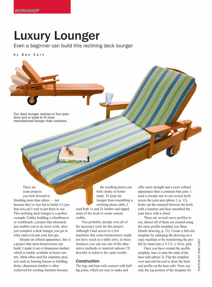
Luxury LoungerEven a beginner can build this reclining deck lounger
b y D a n C a r y
There are
some projects
you look forward to
finishing more than others — not
because they’re less fun to build; it’s just
that you can’t wait to put them to use.
This reclining deck lounger is a perfect
example. Unlike building a wheelbarrow
or workbench, a project that ultimately
just enables you to do more work, once
you complete a deck lounger you get to
relax (and even put your feet up).
Despite its refined appearance, this is
a project that most homeowners can
build. I made it out of dimension lumber,
which is readily available at home cen-
ters. Most often used for carpentry proj-
ects such as framing houses or building
decks, dimension lumber is often
eschewed for creating furniture because
the resulting pieces can
look clunky or home-
made. To keep my
lounger from resembling a
reclining picnic table, I
used both 1x and 2x lumber and ripped
some of the stock to create custom
widths.
You probably already own all of
the necessary tools for this project.
Although I had access to a few
machines that some homeowners might
not have (such as a table saw), in these
instances you can use one of the alter-
native methods or material options I’ll
describe to achieve the same results.
ConstructionThe legs and base rails connect with half-
lap joints, which are easy to make and
offer more strength and a more refined
appearance than a common butt joint. I
used a circular saw to cut several kerfs
across the joint area (photo 1, p. 12),
broke out the material between the kerfs
with a hammer and then smoothed the
joint faces with a chisel.
There are several curve profiles to
cut; almost all of them are created using
the same profile template (see Base
Details drawing, p. 13). Create a full-size
template by enlarging the drawing on a
copy machine or by transferring the pro-
file by hand onto a 5-1/2- x 10-in. grid.
Once you have created the profile
template, trace it onto the ends of the
base rails (photo 2). Flip the template
over and end-for-end to draw the back
end profile on the base rails. Next, use
only the top portion of the template for Ph
Ot
Os
by
da
n c
ar
y
WORKSHOPWORKSHOP
Our deck lounger reclines in four posi-tions and is sized to fit mostmanufactured lounge chair cushions.

the back rails. Then place the front legs across the base rails
in the position that they will later be fastened and adjust the
template on the front legs so that the curve flows into the
front curve on the base rails. Finally, draw the only curves
that don’t follow the template — a
1-1/2-in.-radius half-circle on the bottom of the back leg and
an arc on the front arm support. Cut the curve profiles in
each piece.
The adjustable backrest is supported by two arms that
connect to a dowel. The dowel fits into notches that are cut
into a support rail. The notches are spaced to accommodate
four positions, ranging from lying flat to sitting upright. To
form the notches, first drill 3/4-in.-dia. holes at each notch
position (see Support Rail Detail, p. 13) and then cut
through the top of the support rail to open up the top of
each notch (photo 3). The front cut into each notch is
beveled slightly so that the support bar easily slides out of
the notch when the backrest is lifted, but the back cut is
perpendicular so that the support bar can’t slide out when
you lean on the backrest.
Assemble the base frame and back frame with
exterior-rated glue and screws (photo 4, p. 14). I con-
cealed the screws that fasten the legs by driving them
from the inside of the frame, but not all of the screws are
as easily hidden. So instead of trying to hide all of them,
I used decorative stainless steel washers to enhance the
look of the exposed screws. Next, attach the support rails
to the base rails and glue the support arm spacers to the
inside of the back rails.
Because making the slats out of stock widths of 1x
lumber would have given the piece a clunky appearance, I
ripped 1x4s down the middle to create boards that were a
KEy nO. dEscrIPtIOn sIZE
A 2 base rails 1-1/2 x 5-1/2 x 78 in.
B 4 base stretchers 1-1/2 x 3-1/2 x 24 in.
C 2 back rails 7/8 x 3 x 31 in.
D 2 back stretchers 1-1/2 x 3-1/2 x 22 in.
E 2 Front legs 1-1/2 x 3-1/2 x 14 in.
F 2 back legs 1-1/2 x 3-1/2 x 11-3/4 in.
G 2 support rails 1-1/2 x 1-5/8 x 15 in.
H 12 base slats 7/8 x 1-3/4 x 51 in.
I 12 back slats 7/8 x 1-3/4 x 32-1/2 in.
J 2 back-support spacers 7/8 x 3 x 3 in.
K 2 back-support arms 7/8 x 2 x 15 in.
L 1 back-support bar 3/4 in. dia. x 23-3/4 in.
M 2 Front armrest supports 7/8 x 1-3/4 x 12-3/4 in.
N 2 back armrest supports 7/8 x 1-3/4 x 9 in.
O 2 armrest rails 1-1/2 x 2 x 28 in.
P 2 armrests 7/8 x 4-1/2 x 31 in.
MATERIALS AND CUTTING LISTall parts exterior-rated lumber
SHOPPING LIST1x4 x 8-ft. cedar (8)1x6 x 8-ft. cedar (1)2x4 x 8-ft. cedar (3)2x6 x 8-ft. cedar (2)3/4-in.-dia. x 23-3/4-in. dowel1-1/4-in. stainless steel screws1-5/8-in. stainless steel screws3-in. stainless steel screwsstainless steel finish washers(40)1/4 x 3-in. stainless steel
machine screws (2)1/4 x 3-1/2-in. stainless steel
machine screws (2)1/4-in. stainless steel finish
washers (4)1/4-in. stainless steel
flat washers (8)1/4-in. stainless steel locknuts (4)1/2-in.-dia. x 28-1/2-in.
aluminum rod8-in.-dia. lawn mower wheels (2)1/2-in. stainless steel washers (6)1/2-in.-dia. x 19-1/2-in.
PVc tubing1/2-in. axle push caps (2)
Mark the area on each piece that willoverlap. set the saw blade depth tohalf the thickness of the stock. Makeseveral passes, starting at the insideedge of the half-lap area.
create a curved profile template. Usethe same template to mark the curveprofiles on the base rail, back rail andfront leg. cut along the profile lineswith a jigsaw or band saw.
drill 3/4-in.-dia. holes at each notchposition and then use a handsaw tocut to the edge of each hole. bevel thefront cut, and keep the back cut per-pendicular to the top.
1 2 3
Bevel cut
Straight cut

24" radius curveHalf-lap legs and base rails
24" radius curve
Each square = 2"
8-1/2"
45"
Half-lap legs and base rails
26-1/2 " 28"16"
3-7/8"
2-3/8"
7/8"
2-1/2"2"
3-1/2"
Trim to fit
1-1/2"2"
3"
12-3/4" 12-1/2"
4-1/2"
1-1/2"
4" radius 3" radius
9" 1-1/2"
1-1/2"
11-1/2"
1-1/2"Bore 3/4" dia.holes and cut sidewalls with saw
3-1/4"5"
7-1/2"10"
10"
1/4 x 3-1/2" machine screwand finish washer
1/4 x 3" machine screwand finishwasher
Washers andlocknuts
26"
12-1/2"
5-1/2"
22-1/2"
1"
1/4" dia.holes
1/4" dia. hole 1/2" dia.hole
3/4" dia.hole1" rad. 1" rad.
3"
2" 8" dia. wheel
1-1/4"fhws
1-1/4" fhws andfinish washers
3" fhws andfinish washers(typical)
1-5/8"fhwsand plug
1-5/8" fhws(typical)
8" dia. wheel
1/2" i.d. washers
1/2" i.d. PVC tube1/2" i.d. washer
1/2" dia. steel rod 1/2" axle push cap
3"
BASE DETAILS
BACK DETAILS
ARMREST DETAILS
SUPPORT RAIL DETAIL
E
E
H
A
A
A
A
A
F
F
F
B
B
B
B
B
B
B
B
K
K
K
C
C
C
D
D
D
D
H
H
I
I
J
J
J
L
G
G
G
M
N
O
P
M
N O
P
DECK LOUNGER
IllUstratIOn by gabrIEl graPhIcs
HANDY M A g A z I N e
little less than 1-3/4 in. wide. (This
approach also left very little waste.) I
ripped a few extra feet of 1x4 to use for
the armrest supports and back-support
arms. If you don’t have access to a table
saw to rip the 1x4s, your best option is to
substitute 1x2s and add two slats — the
spacing will be just a little less than 1/4
in.
I eased the top long edges of each
slat with a router and 1/8-in.-radius
roundover bit. Then I attached the slats to
the base and back frames with 1-5/8-in.
stainless steel screws, leaving slightly
more than 1/4 in. between slats. Test the
spacing before attaching any slats. I
countersunk all of the slat screws slightly
below the surface and did not use the fin-
ish washers.
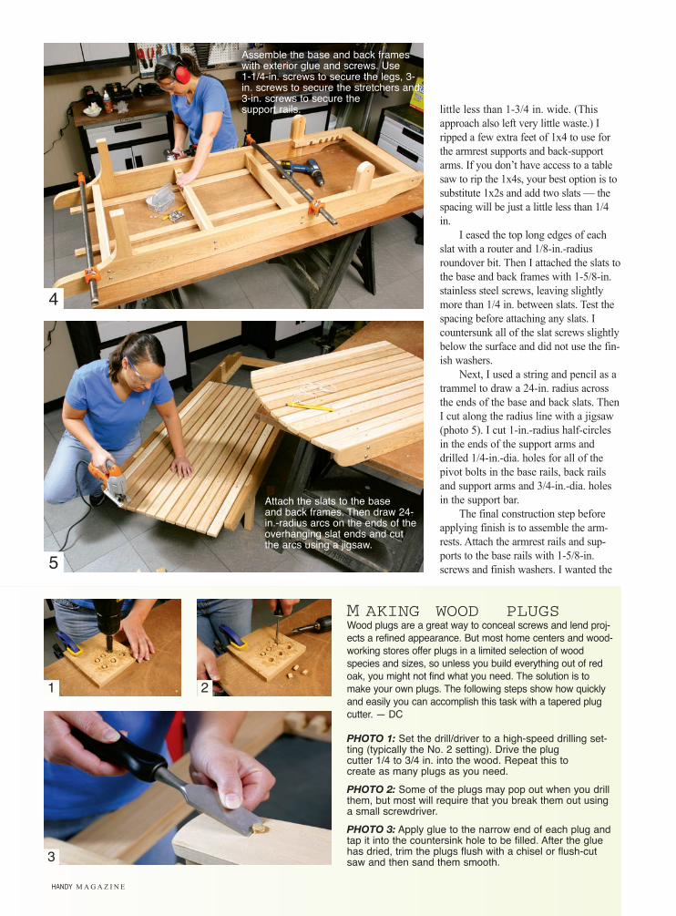
Next, I used a string and pencil as a
trammel to draw a 24-in. radius across
the ends of the base and back slats. Then
I cut along the radius line with a jigsaw
(photo 5). I cut 1-in.-radius half-circles
in the ends of the support arms and
drilled 1/4-in.-dia. holes for all of the
pivot bolts in the base rails, back rails
and support arms and 3/4-in.-dia. holes
in the support bar.
The final construction step before
applying finish is to assemble the arm-
rests. Attach the armrest rails and sup-
ports to the base rails with 1-5/8-in.
screws and finish washers. I wanted the
M AKING WOOD PLUGSWood plugs are a great way to conceal screws and lend proj-
ects a refined appearance. but most home centers and wood-
working stores offer plugs in a limited selection of wood
species and sizes, so unless you build everything out of red
oak, you might not find what you need. the solution is to
make your own plugs. the following steps show how quickly
and easily you can accomplish this task with a tapered plug
cutter. — dc
PHOTO 1: set the drill/driver to a high-speed drilling set-ting (typically the no. 2 setting). drive the plugcutter 1/4 to 3/4 in. into the wood. repeat this tocreate as many plugs as you need.
PHOTO 2: some of the plugs may pop out when you drillthem, but most will require that you break them out usinga small screwdriver.
PHOTO 3: apply glue to the narrow end of each plug andtap it into the countersink hole to be filled. after the gluehas dried, t rim the plugs flush with a chisel or flush-cutsaw and then sand them smooth.
4
5
1 2
3
assemble the base and back frameswith exterior glue and screws. Use1-1/4-in. screws to secure the legs, 3-in. screws to secure the stretchers and3-in. screws to secure thesupport rails.
attach the slats to the baseand back frames. then draw 24-in.-radius arcs on the ends of theoverhanging slat ends and cutthe arcs using a jigsaw.

HANDYMAGAZINE.com
armrests to be smooth and comfortable,
so I fastened them to the armrest rails
with exterior glue and 1-5/8-in. screws
that are recessed in countersunk holes
and covered with wood plugs (photo 6).
Cedar plugs are not readily available, so
I cut the plugs myself (see “Making
Wood Plugs,” opposite).
Finish and assemblyease any exposed rough edges with a
router and 1/8-in.-radius roundover bit or
sandpaper. Sand the rest of the lounger
smooth with 150-grit sandpaper and then
apply the finish. I applied one coat of a
penetrating oil finish (see SOURCeS
ONLINe).
Once the finish has cured, attach
the backrest to the base with 1/4-in.-dia.
x 3-1/2-in. exterior machine screws,
washers and locknuts (photo 7). Then
attach the support arms to the back rail
with 1/4-in.-dia. x 3-in. exterior
machine screws, washers and locknuts.
Slide the support bar through the holes
in the support arms.
The deck lounger rolls on a set of
8-in.-dia. lawn mower wheels that are
mounted on a 1/2-in.-dia. aluminum rod
as an axle. Both the wheels and the alu-
minum rod are available at most home
centers and hardware stores. To partially
conceal the wheels, I mounted them
inside the back legs. I fit a piece of
1/2-in.-i.d. (inside diameter) PVC pipe
over the axle and between the wheels to
keep the wheels tight against the legs.
The axle is retained with 1/2-in. push
caps (photo 8), which are available at
most hardware stores and home centers.
Push caps feature metal flanges that are
angled to slide onto the rod, but when
you try to pull them off, the flange digs
into the rod and will not slide off.
Once the wheels are in place, the
anticipation is over — your deck lounger
is ready for extensive use-testing. Try not
to sleep through dinner. u
Behr (Premium Weatherproofing WoodFinish, Natural Cedar), 800-854-0133, ext. 2
Rockler Woodworking (plug cutters)800-279-4441
For online information, go towww.handymanclub.com
attach the armrests to the armrestrails and supports. If you are talleror shorter than average, you canadjust the armrest height byincreasing or decreasing the sup-port lengths.
attach the back assembly to the base assembly with bolts, washers and lock-nuts. then attach the support arms to the back frame.
clamp a scrap ofwood against theopposite end of theaxle to hold itsecurely in placewhen pounding thepush caps onto theaxle.
7
8
6
Scrap board