Embed Size (px)
Citation preview

Decimeter Accurate, Long Range Non-Line-of-Sight RF Wireless Localization Solution for Public Safety Applications
Hun-Seok KimAssistant Professor
EECS, University of Michigan

2
DISCLAIMER
This presentation was produced by guest speaker(s) and presented at the National Institute of Standards
and Technology’s 2019 Public Safety Broadband Stakeholder Meeting. The contents of this
presentation do not necessarily reflect the views or policies of the National Institute of Standards and
Technology or the U.S. Government.
Posted with permission

Motivation: Fast and Accurate Indoor Localization
§ Applications for Indoor Localization§ Public safety
§ Firefighter / first responder rescue operations§ Emergency evacuation path planning / guidance§ Medicine, equipment, patients, and staffs in
hospitals§ Customer Applications
§ Indoor navigation (airport, retail malls, museum, conference center, etc.)
§ Industrial Applications• Intelligent logistics by tracking robots, packages,
and workers in warehouses
Image from http://scanonline.com/rtls/
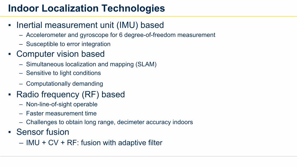
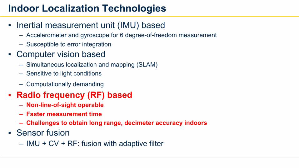
Indoor Localization Technologies▪ Inertial measurement unit (IMU) based
– Accelerometer and gyroscope for 6 degree-of-freedom measurement– Susceptible to error integration
▪ Computer vision based– Simultaneous localization and mapping (SLAM)– Sensitive to light conditions
– Computationally demanding
▪ Radio frequency (RF) based– Non-line-of-sight operable– Faster measurement time– Challenges to obtain long range, decimeter accuracy indoors
▪ Sensor fusion– IMU + CV + RF: fusion with adaptive filter
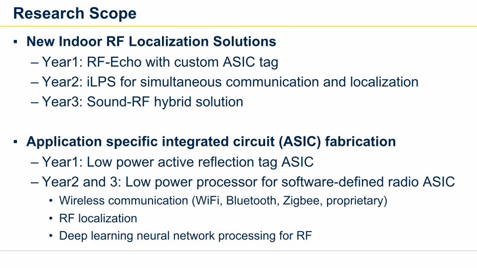
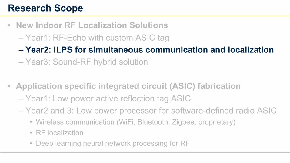
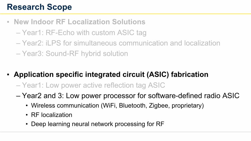
Research Scope▪ New Indoor RF Localization Solutions
– Year1: RF-Echo with custom ASIC tag– Year2: iLPS for simultaneous communication and localization– Year3: Sound-RF hybrid solution
▪ Application specific integrated circuit (ASIC) fabrication– Year1: Low power active reflection tag ASIC– Year2 and 3: Low power processor for software-defined radio ASIC
• Wireless communication (WiFi, Bluetooth, Zigbee, proprietary)• RF localization• Deep learning neural network processing for RF
Available RF Localization Solutions and Challenges
7
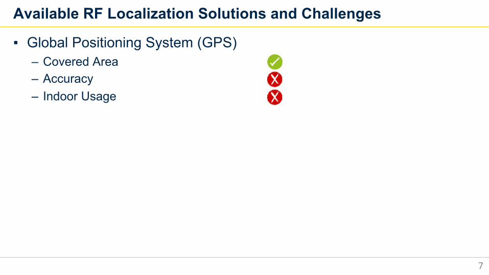
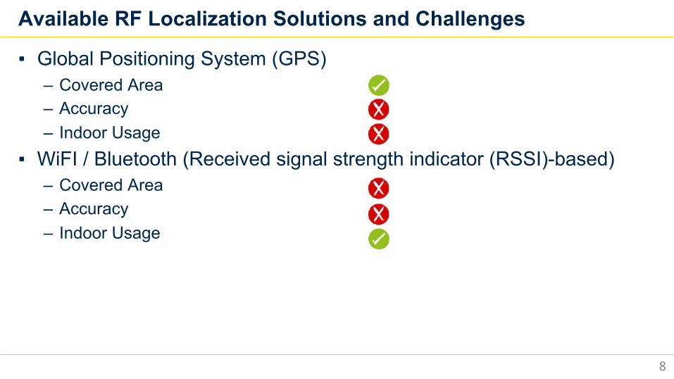
▪ Global Positioning System (GPS)– Covered Area– Accuracy– Indoor Usage
Available RF Localization Solutions and Challenges
8
▪ Global Positioning System (GPS)– Covered Area– Accuracy– Indoor Usage
▪ WiFI / Bluetooth (Received signal strength indicator (RSSI)-based)– Covered Area– Accuracy– Indoor Usage
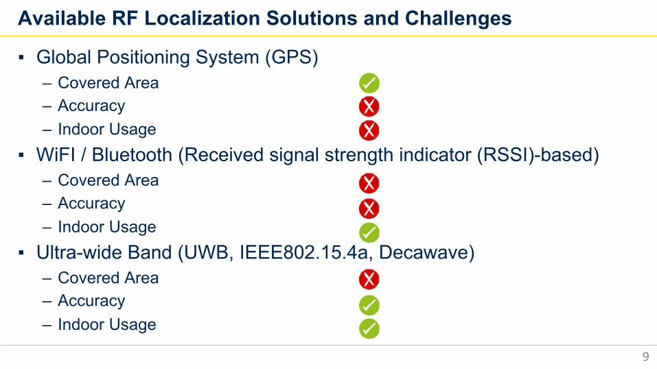
Available RF Localization Solutions and Challenges
9
▪ Global Positioning System (GPS)– Covered Area– Accuracy– Indoor Usage
▪ WiFI / Bluetooth (Received signal strength indicator (RSSI)-based)– Covered Area– Accuracy– Indoor Usage
▪ Ultra-wide Band (UWB, IEEE802.15.4a, Decawave)– Covered Area– Accuracy– Indoor Usage
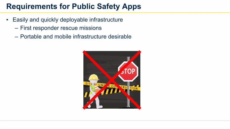
Requirements for Public Safety Apps▪ Easily and quickly deployable infrastructure
– First responder rescue missions– Portable and mobile infrastructure desirable
Requirements for Public Safety Apps▪ Easily and quickly deployable infrastructure
– First responder rescue missions– Portable and mobile infrastructure desirable
▪ Decimeter-level accuracy in non-line-of-sight indoors– Long range (~100m) operable– Milli-second refresh rate, tens of centimeter accuracy
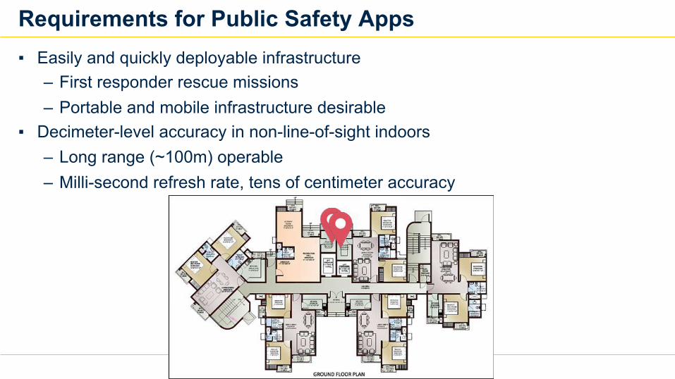
Requirements for Public Safety Apps▪ Easily and quickly deployable infrastructure
– First responder rescue missions– Portable and mobile infrastructure desirable
▪ Decimeter-level accuracy in non-line-of-sight indoors – Long range (~100m) operable– Milli-second refresh rate, tens of centimeter accuracy
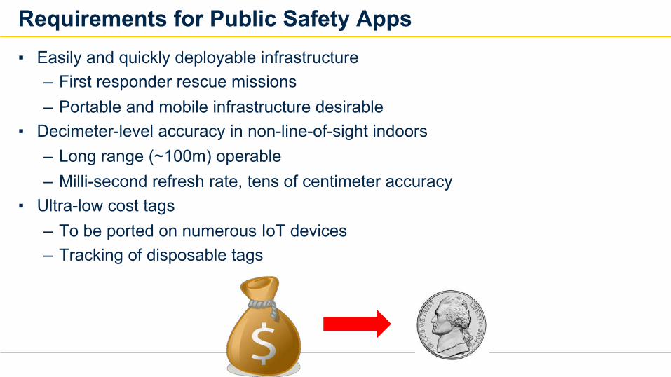
▪ Ultra-low cost tags– To be ported on numerous IoT devices– Tracking of disposable tags
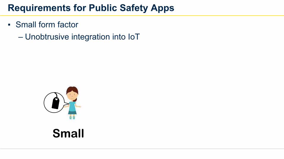
Requirements for Public Safety Apps▪ Small form factor
– Unobtrusive integration into IoT
Small
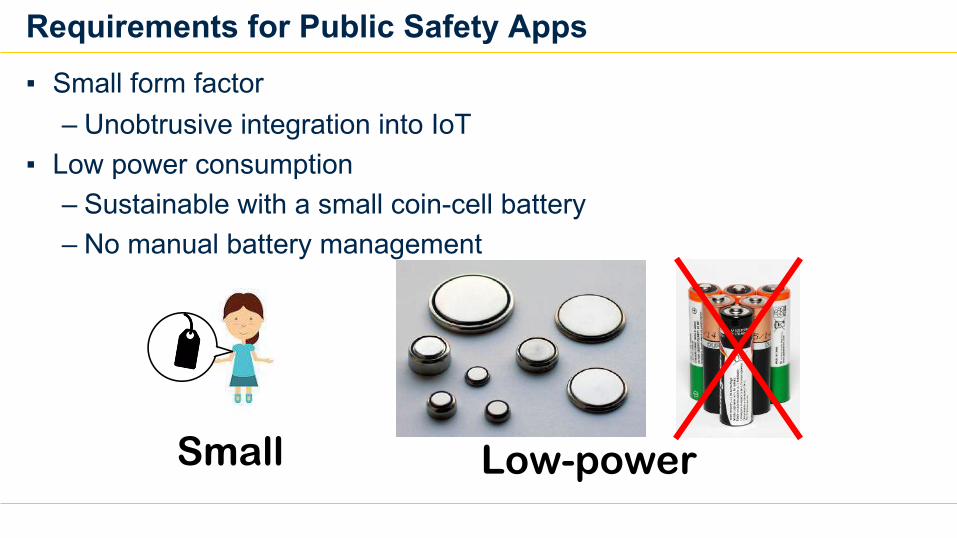
Requirements for Public Safety Apps▪ Small form factor
– Unobtrusive integration into IoT▪ Low power consumption
– Sustainable with a small coin-cell battery– No manual battery management
Small Low-power
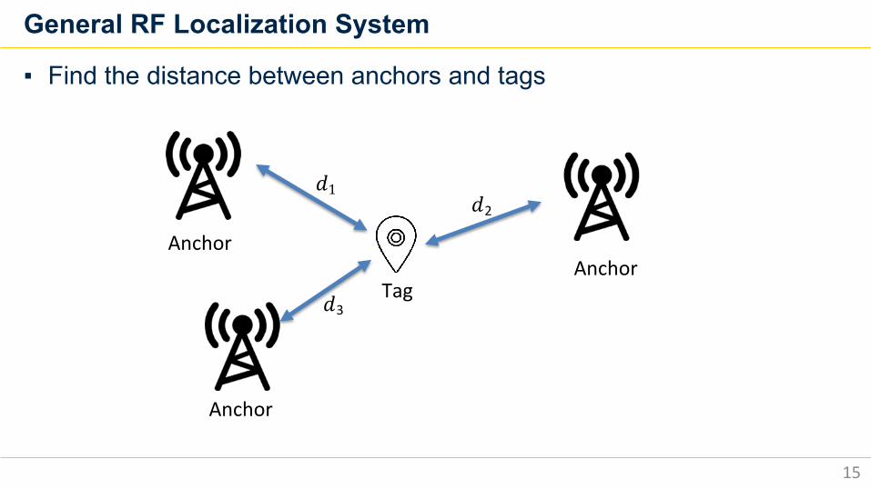
General RF Localization System
15
▪ Find the distance between anchors and tags
Anchor
Anchor
Anchor
Tag
𝑑1
𝑑3
𝑑2
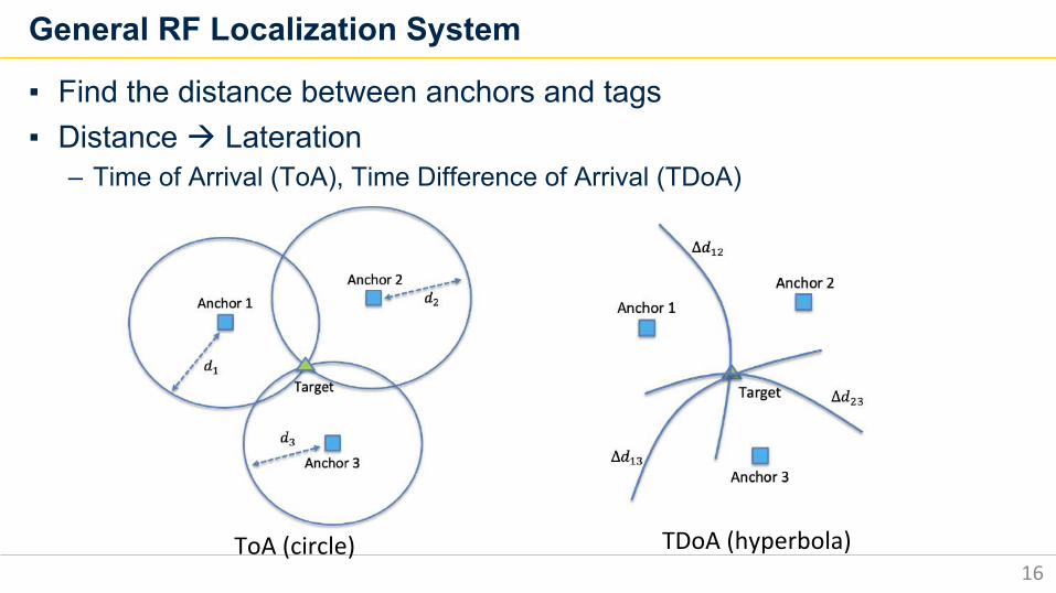
General RF Localization System
16
▪ Find the distance between anchors and tags▪ Distance à Lateration
– Time of Arrival (ToA), Time Difference of Arrival (TDoA)
ToA (circle) TDoA (hyperbola)
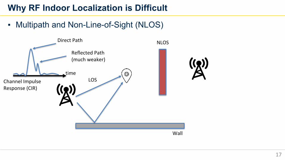
Why RF Indoor Localization is Difficult
17
▪ Multipath and Non-Line-of-Sight (NLOS)
Wall
NLOS
LOStime
Direct Path
Reflected Path (much weaker)
Channel Impulse Response (CIR)
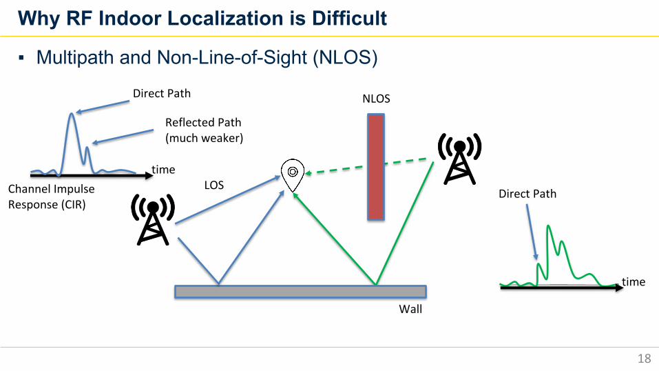
Why RF Indoor Localization is Difficult
18
▪ Multipath and Non-Line-of-Sight (NLOS)
Wall
NLOS
LOStime
Direct Path
time
Direct Path
Reflected Path (much weaker)
Channel Impulse Response (CIR)
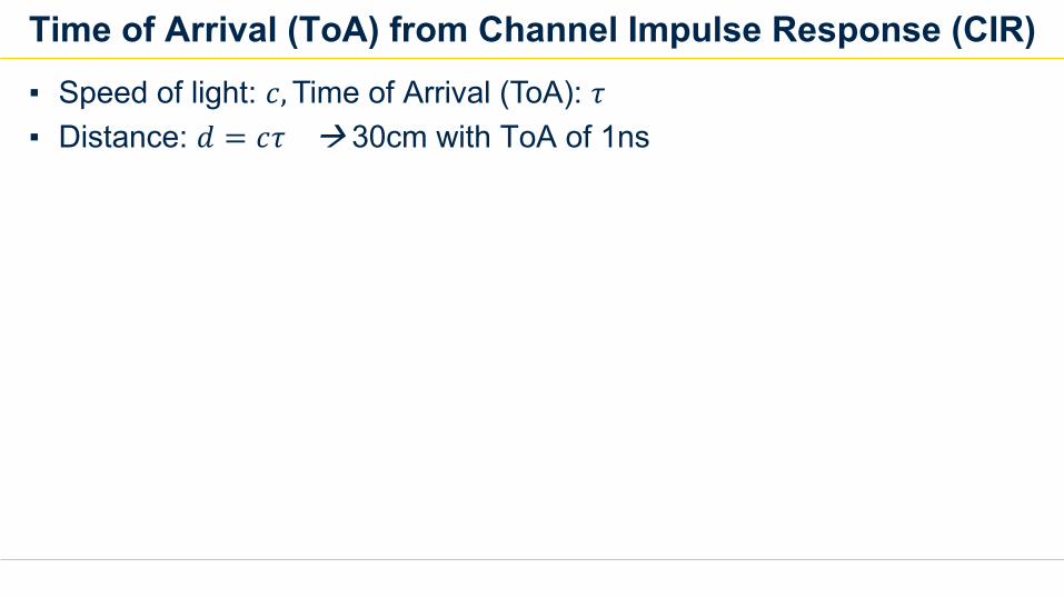
Time of Arrival (ToA) from Channel Impulse Response (CIR)▪ Speed of light: 𝑐,Time of Arrival (ToA): 𝜏▪ Distance: 𝑑 = 𝑐𝜏 à 30cm with ToA of 1ns
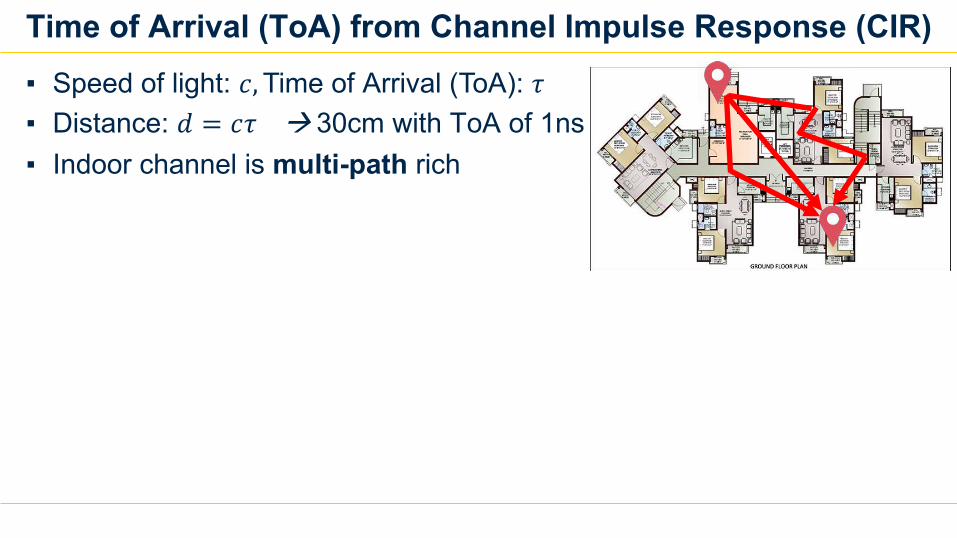
Time of Arrival (ToA) from Channel Impulse Response (CIR)▪ Speed of light: 𝑐,Time of Arrival (ToA): 𝜏▪ Distance: 𝑑 = 𝑐𝜏 à 30cm with ToA of 1ns▪ Indoor channel is multi-path rich
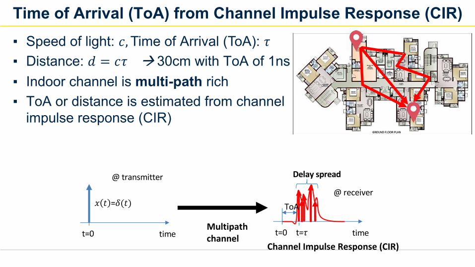
Time of Arrival (ToA) from Channel Impulse Response (CIR)▪ Speed of light: 𝑐,Time of Arrival (ToA): 𝜏▪ Distance: 𝑑 = 𝑐𝜏 à 30cm with ToA of 1ns▪ Indoor channel is multi-path rich▪ ToA or distance is estimated from channel
impulse response (CIR)
t=0 time t=0 timet=𝜏
𝑥 𝑡 =𝛿(𝑡)@ receiver
@ transmitter
Multipath channel
Delay spread
ToA
Channel Impulse Response (CIR)
TDoA Localization Challenges
22
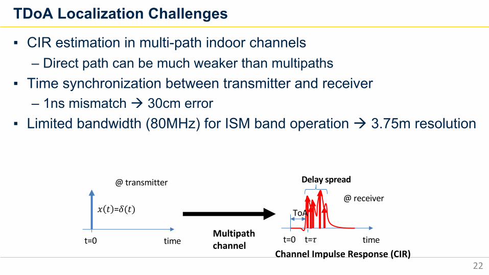
▪ CIR estimation in multi-path indoor channels– Direct path can be much weaker than multipaths
▪ Time synchronization between transmitter and receiver– 1ns mismatch à 30cm error
▪ Limited bandwidth (80MHz) for ISM band operation à 3.75m resolution
t=0 time t=0 timet=𝜏
𝑥 𝑡 =𝛿(𝑡)@ receiver
@ transmitter
Multipath channel
Delay spread
ToA
Channel Impulse Response (CIR)
Proposed System: RF-Echo and iLPS
23
▪ Decimeter-level (tens of centimeter) ranging accuracy▪ Large covered area: >100m distance▪ GPS-like local positioning scheme
– Indefinite number of tags localize themselves simultaneously ▪ Reliable wireless communications between anchors and tags
– Localization and communication at the same time▪ Deployable without heavy infrastructure investment
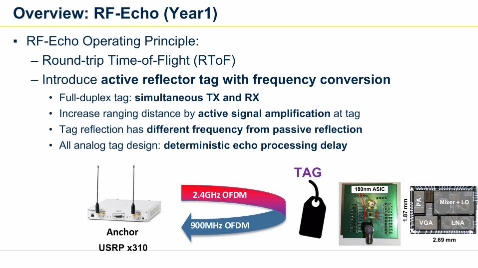
Overview: RF-Echo (Year1)▪ RF-Echo Operating Principle:
– Round-trip Time-of-Flight (RToF)– Introduce active reflector tag with frequency conversion
• Full-duplex tag: simultaneous TX and RX• Increase ranging distance by active signal amplification at tag• Tag reflection has different frequency from passive reflection• All analog tag design: deterministic echo processing delay
TAG
Anchor
2.4GHz OFDM
900MHz OFDM
180nm ASIC
TagUSRP x310
LNA
Mixer + LO
VGA
PA
2.69 mm
1.87
mm
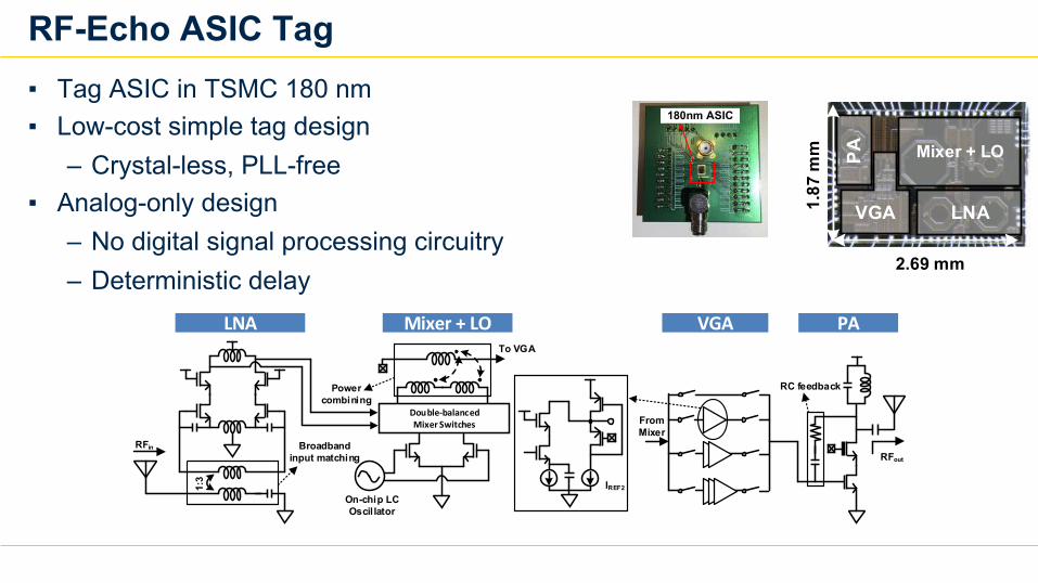
RF-Echo ASIC Tag▪ Tag ASIC in TSMC 180 nm▪ Low-cost simple tag design
– Crystal-less, PLL-free▪ Analog-only design
– No digital signal processing circuitry– Deterministic delay
RFin
1:3
On-chip LC Oscil lator
Double-balanced Mixer Switches
To VGA
Broadband input matching
Power combining
From Mixer
IREF2
RFout
RC feedback
LNA Mixer + LO VGA PA
LNA
Mixer + LO
VGA
PA
2.69 mm
1.87
mm
180nm ASIC
Tag
180nm ASIC
Tag
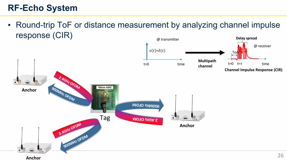
RF-Echo System
26
▪ Round-trip ToF or distance measurement by analyzing channel impulse response (CIR)
Tag
Anchor
2.4GHz OFDM900MHz OFDM
2.4GHz OFDM
900MHz OFDM
Anchor
2.4GHz OFDM
900MHz OFDM
Anchor
t=0 time t=0 timet=!
" # =$(#)@ receiver
@ transmitter
Multipath channel
Delay spread
ToA
Channel Impulse Response (CIR)
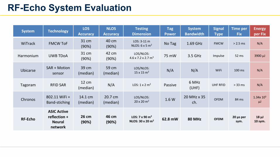
RF-Echo System Evaluation
System Technology LOSAccuracy
NLOSAccuracy
TestingDimension
Tag Power
System Bandwidth
Signal Type
Time per Fix
Energy per Fix
WiTrack FMCW ToF 31 cm(90%)
40 cm(90%)
LOS: 3-11 mNLOS: 6 x 5 m2 No Tag 1.69 GHz FMCW > 2.5 ms N/A
Harmonium UWB TDoA 31 cm(90%)
42 cm(90%)
LOS/NLOS: 4.6 x 7.2 x 2.7 m3 75 mW 3.5 GHz Impulse 52 ms 3900 µJ
Ubicarse SAR + Motion sensor
39 cm(median)
59 cm(median)
LOS/NLOS: 15 x 15 m2 N/A N/A WiFi 100 ms N/A
Tagoram RFID SAR 12 cm(median)
N/A LOS: 1 x 2 m2 Passive 6 MHz(UHF)
UHF RFID > 33 ms N/A
Chronos 802.11 WiFi + Band-stiching
14.1 cm(median)
20.7 cm(median)
LOS/NLOS: 20 x 20 m2 1.6 W 20 MHz x 35
ch.OFDM 84 ms 1.34x 10⁵
µJ
RF-Echo
ASIC Active reflection +
Neural network
26 cm(90%)
46 cm(90%)
LOS: 7 x 90 m2
NLOS: 30 x 20 m2 62.8 mW 80 MHz OFDM 20 µs per sym.
18 µJ10 sym.
Research Scope▪ New Indoor RF Localization Solutions
– Year1: RF-Echo with custom ASIC tag– Year2: iLPS for simultaneous communication and localization– Year3: Sound-RF hybrid solution
▪ Application specific integrated circuit (ASIC) fabrication– Year1: Low power active reflection tag ASIC– Year2 and 3: Low power processor for software-defined radio ASIC
• Wireless communication (WiFi, Bluetooth, Zigbee, proprietary)• RF localization• Deep learning neural network processing for RF
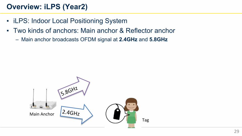
Overview: iLPS (Year2)
29
▪ iLPS: Indoor Local Positioning System▪ Two kinds of anchors: Main anchor & Reflector anchor
– Main anchor broadcasts OFDM signal at 2.4GHz and 5.8GHz
2.4GHzMain AnchorTag
5.8GHz
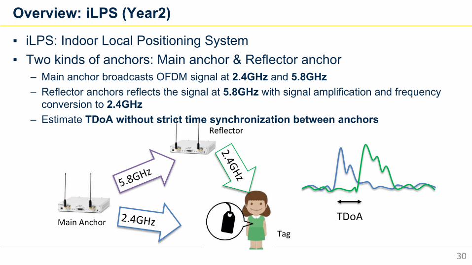
Overview: iLPS (Year2)
30
▪ iLPS: Indoor Local Positioning System▪ Two kinds of anchors: Main anchor & Reflector anchor
– Main anchor broadcasts OFDM signal at 2.4GHz and 5.8GHz– Reflector anchors reflects the signal at 5.8GHz with signal amplification and frequency
conversion to 2.4GHz– Estimate TDoA without strict time synchronization between anchors
5.8GHz
2.4GHz
2.4GHzTDoAMain Anchor
Reflector
Tag
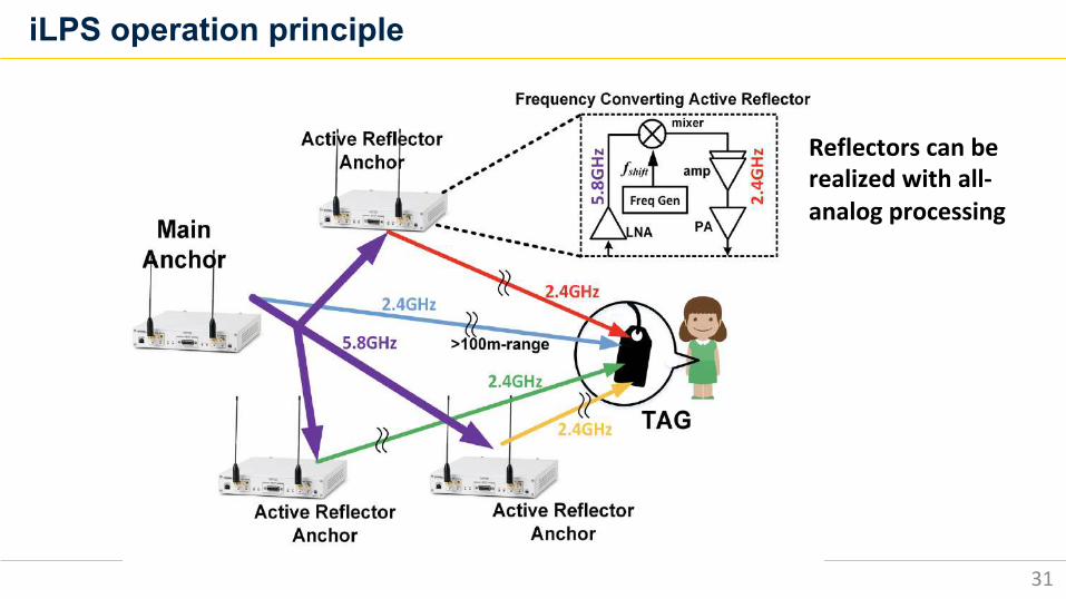
iLPS operation principle
31
Reflectors can be realized with all-analog processing
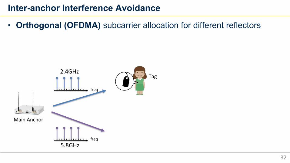
Inter-anchor Interference Avoidance
32
▪ Orthogonal (OFDMA) subcarrier allocation for different reflectors
2.4GHz
5.8GHz
Main Anchor
Tag
freq
freq
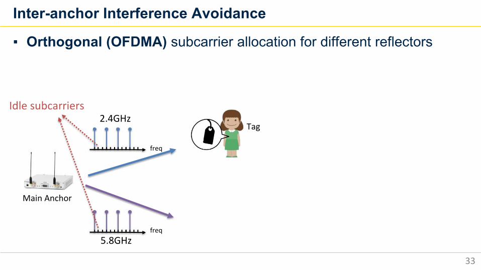
Inter-anchor Interference Avoidance
33
▪ Orthogonal (OFDMA) subcarrier allocation for different reflectors
2.4GHz
5.8GHz
Main Anchor
Idle subcarriers
Tag
freq
freq
Inter-anchor Interference Avoidance
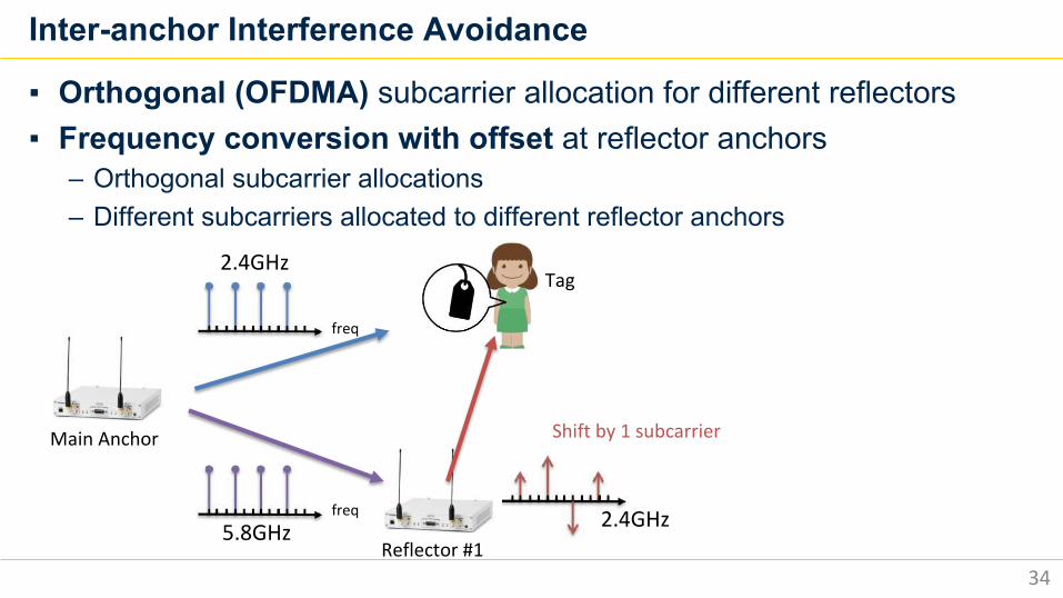
34
▪ Orthogonal (OFDMA) subcarrier allocation for different reflectors▪ Frequency conversion with offset at reflector anchors
– Orthogonal subcarrier allocations– Different subcarriers allocated to different reflector anchors
2.4GHz
5.8GHz
Main Anchor
Reflector #1
Tag
Shift by 1 subcarrier
2.4GHz
freq
freq
Inter-anchor Interference Avoidance
35
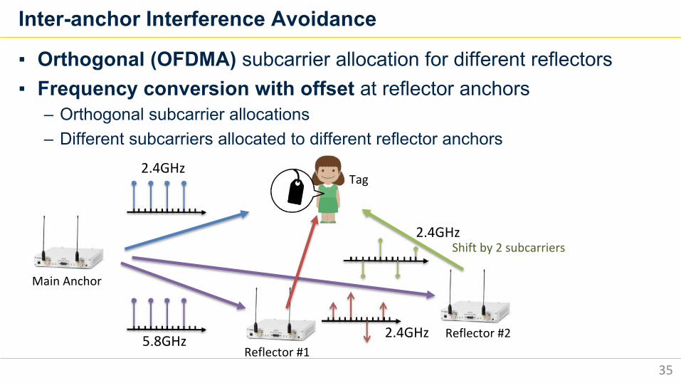
▪ Orthogonal (OFDMA) subcarrier allocation for different reflectors▪ Frequency conversion with offset at reflector anchors
– Orthogonal subcarrier allocations– Different subcarriers allocated to different reflector anchors
2.4GHz
5.8GHz
Main Anchor
Reflector #1Reflector #2
Tag
2.4GHz
2.4GHzShift by 2 subcarriers
Tag
Inter-anchor Interference Avoidance
36
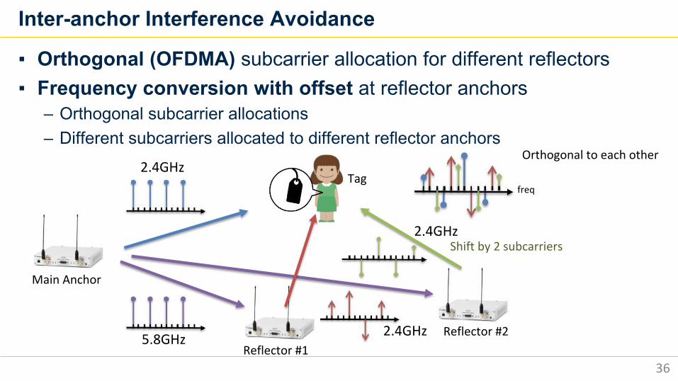
▪ Orthogonal (OFDMA) subcarrier allocation for different reflectors▪ Frequency conversion with offset at reflector anchors
– Orthogonal subcarrier allocations– Different subcarriers allocated to different reflector anchors
2.4GHz
5.8GHz
Main Anchor
Reflector #1Reflector #2
Orthogonal to each other
2.4GHz
2.4GHz
freq
Shift by 2 subcarriers
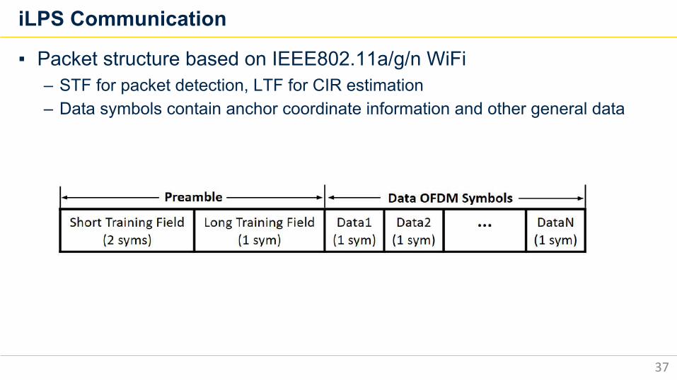
iLPS Communication
37
▪ Packet structure based on IEEE802.11a/g/n WiFi– STF for packet detection, LTF for CIR estimation– Data symbols contain anchor coordinate information and other general data
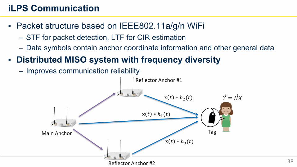
iLPS Communication
38
▪ Packet structure based on IEEE802.11a/g/n WiFi– STF for packet detection, LTF for CIR estimation– Data symbols contain anchor coordinate information and other general data
▪ Distributed MISO system with frequency diversity– Improves communication reliability
x 𝑡 ∗ ℎ/(𝑡)
x 𝑡 ∗ ℎ0(𝑡)
x 𝑡 ∗ ℎ1(𝑡)Main Anchor
Reflector Anchor #1
Reflector Anchor #2
Tag
𝑌 = 𝐻𝑋
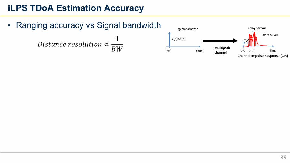
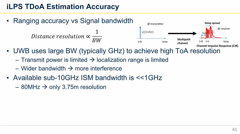
iLPS TDoA Estimation Accuracy
39
▪ Ranging accuracy vs Signal bandwidth
𝐷𝑖𝑠𝑡𝑎𝑛𝑐𝑒 𝑟𝑒𝑠𝑜𝑙𝑢𝑡𝑖𝑜𝑛 ∝1𝐵𝑊 t=0 time t=0 timet=!
" # =$(#)@ receiver
@ transmitter
Multipath channel
Delay spread
ToA
Channel Impulse Response (CIR)
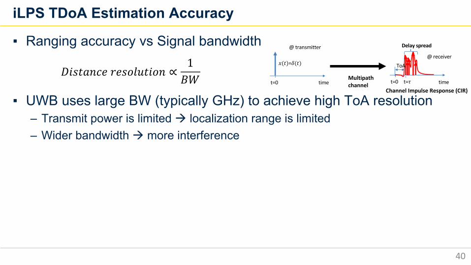
iLPS TDoA Estimation Accuracy
40
▪ Ranging accuracy vs Signal bandwidth
▪ UWB uses large BW (typically GHz) to achieve high ToA resolution– Transmit power is limited à localization range is limited – Wider bandwidth à more interference
𝐷𝑖𝑠𝑡𝑎𝑛𝑐𝑒 𝑟𝑒𝑠𝑜𝑙𝑢𝑡𝑖𝑜𝑛 ∝1𝐵𝑊 t=0 time t=0 timet=!
" # =$(#)@ receiver
@ transmitter
Multipath channel
Delay spread
ToA
Channel Impulse Response (CIR)
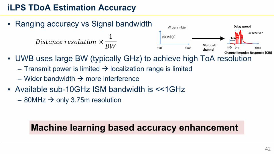
iLPS TDoA Estimation Accuracy
41
▪ Ranging accuracy vs Signal bandwidth
▪ UWB uses large BW (typically GHz) to achieve high ToA resolution– Transmit power is limited à localization range is limited – Wider bandwidth à more interference
▪ Available sub-10GHz ISM bandwidth is <<1GHz – 80MHz à only 3.75m resolution
𝐷𝑖𝑠𝑡𝑎𝑛𝑐𝑒 𝑟𝑒𝑠𝑜𝑙𝑢𝑡𝑖𝑜𝑛 ∝1𝐵𝑊 t=0 time t=0 timet=!
" # =$(#)@ receiver
@ transmitter
Multipath channel
Delay spread
ToA
Channel Impulse Response (CIR)
iLPS TDoA Estimation Accuracy
42
▪ Ranging accuracy vs Signal bandwidth
▪ UWB uses large BW (typically GHz) to achieve high ToA resolution– Transmit power is limited à localization range is limited – Wider bandwidth à more interference
▪ Available sub-10GHz ISM bandwidth is <<1GHz – 80MHz à only 3.75m resolution
𝐷𝑖𝑠𝑡𝑎𝑛𝑐𝑒 𝑟𝑒𝑠𝑜𝑙𝑢𝑡𝑖𝑜𝑛 ∝1𝐵𝑊
Machine learning based accuracy enhancement
t=0 time t=0 timet=!
" # =$(#)@ receiver
@ transmitter
Multipath channel
Delay spread
ToA
Channel Impulse Response (CIR)
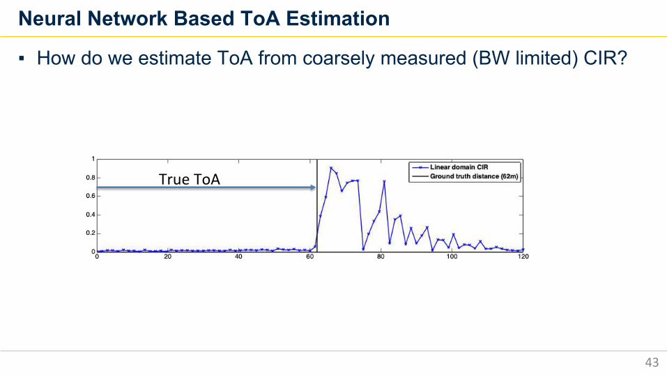
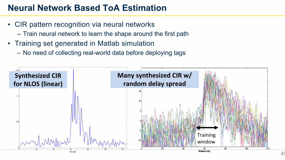
Neural Network Based ToA Estimation
43
▪ How do we estimate ToA from coarsely measured (BW limited) CIR?
True ToA
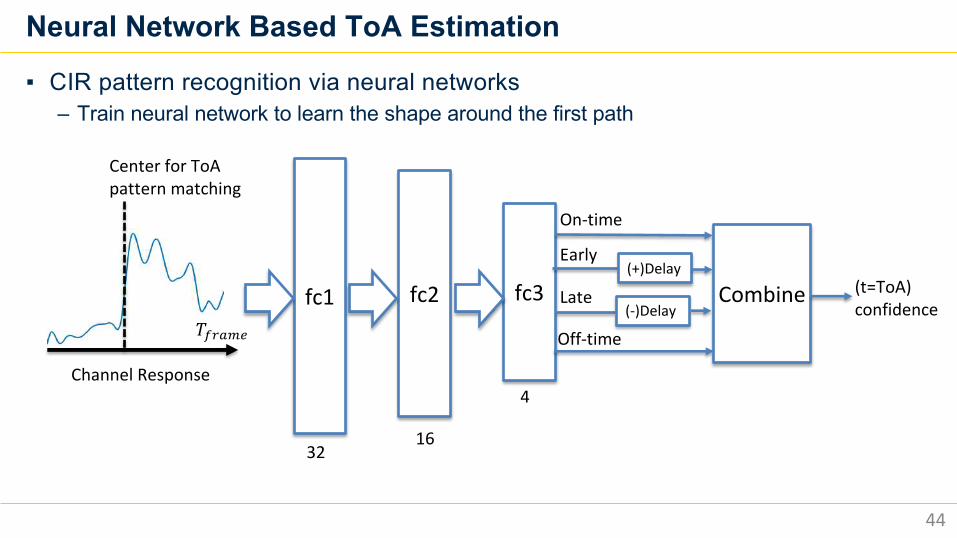
Neural Network Based ToA Estimation
44
▪ CIR pattern recognition via neural networks– Train neural network to learn the shape around the first path
fc1 fc2 fc3
On-time
(+)DelayEarly
(-)DelayLate
Off-time
Combine (t=ToA) confidence
3216
4
Center for ToApattern matching
Channel Response
𝑇CDEFG
0 20 40 60 80 100 1200
0.05
0.1
0.15
Time index
Neural Network Based ToA Estimation
45
▪ CIR pattern recognition via neural networks– Train neural network to learn the shape around the first path
▪ Training set generated in Matlab simulation– No need of collecting real-world data before deploying tags
Synthesized CIR for NLOS (linear)
Many synthesized CIR w/ random delay spread
Training window
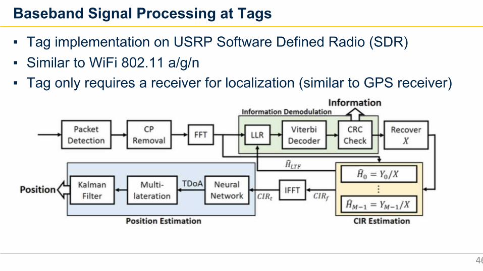
Baseband Signal Processing at Tags
46
▪ Tag implementation on USRP Software Defined Radio (SDR)▪ Similar to WiFi 802.11 a/g/n▪ Tag only requires a receiver for localization (similar to GPS receiver)
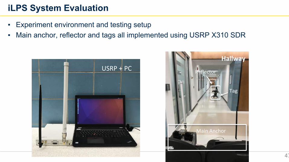
iLPS System Evaluation
47
▪ Experiment environment and testing setup▪ Main anchor, reflector and tags all implemented using USRP X310 SDR
USRP + PC
Tag
Hallway
Main Anchor
Reflector
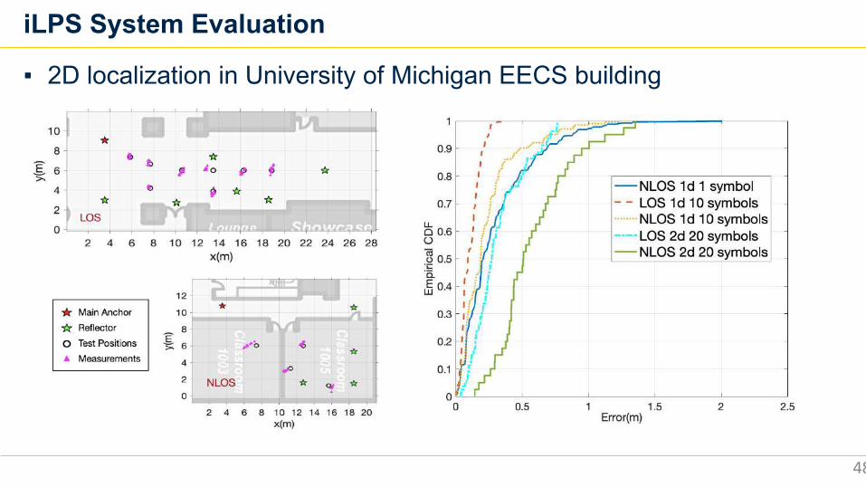
iLPS System Evaluation
48
▪ 2D localization in University of Michigan EECS building
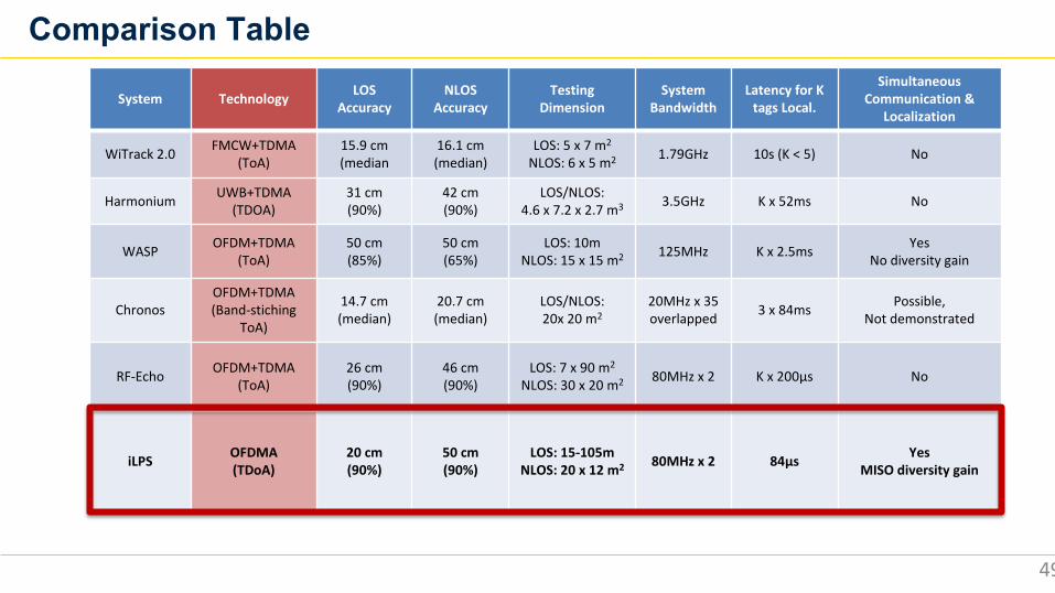
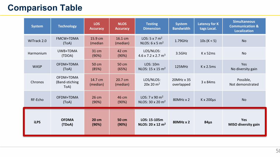
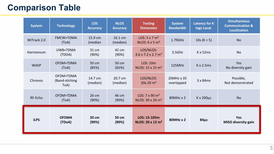
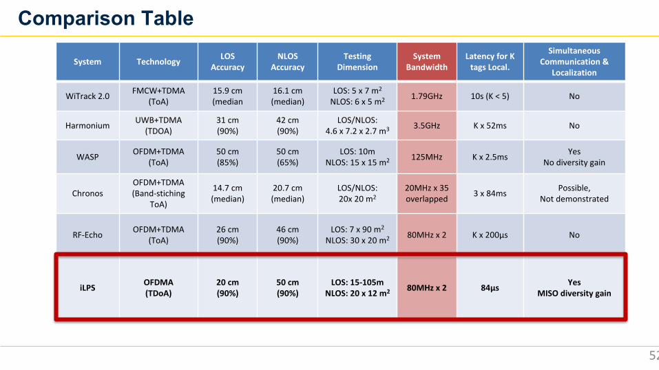
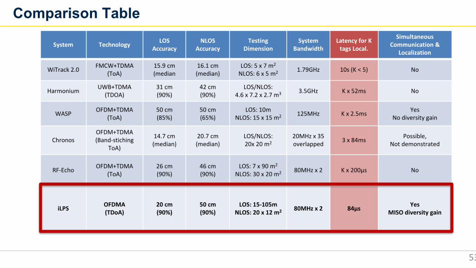
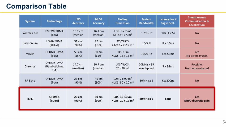
Comparison Table
49
System Technology LOSAccuracy
NLOSAccuracy
TestingDimension
System Bandwidth
Latency for K tags Local.
Simultaneous Communication &
Localization
WiTrack 2.0 FMCW+TDMA (ToA)
15.9 cm(median
16.1 cm(median)
LOS: 5 x 7 m2
NLOS: 6 x 5 m2 1.79GHz 10s (K < 5) No
Harmonium UWB+TDMA (TDOA)
31 cm(90%)
42 cm(90%)
LOS/NLOS: 4.6 x 7.2 x 2.7 m3 3.5GHz K x 52ms No
WASP OFDM+TDMA(ToA)
50 cm(85%)
50 cm(65%)
LOS: 10mNLOS: 15 x 15 m2 125MHz K x 2.5ms Yes
No diversity gain
ChronosOFDM+TDMA(Band-stiching
ToA)
14.7 cm(median)
20.7 cm(median)
LOS/NLOS: 20x 20 m2
20MHz x 35overlapped 3 x 84ms Possible,
Not demonstrated
RF-Echo OFDM+TDMA(ToA)
26 cm(90%)
46 cm(90%)
LOS: 7 x 90 m2
NLOS: 30 x 20 m2 80MHz x 2 K x 200µs No
iLPS OFDMA(TDoA)
20 cm(90%)
50 cm(90%)
LOS: 15-105mNLOS: 20 x 12 m2 80MHz x 2 84µs Yes
MISO diversity gain
Comparison Table
50
System Technology LOSAccuracy
NLOSAccuracy
TestingDimension
System Bandwidth
Latency for K tags Local.
Simultaneous Communication &
Localization
WiTrack 2.0 FMCW+TDMA (ToA)
15.9 cm(median
16.1 cm(median)
LOS: 5 x 7 m2
NLOS: 6 x 5 m2 1.79GHz 10s (K < 5) No
Harmonium UWB+TDMA (TDOA)
31 cm(90%)
42 cm(90%)
LOS/NLOS: 4.6 x 7.2 x 2.7 m3 3.5GHz K x 52ms No
WASP OFDM+TDMA(ToA)
50 cm(85%)
50 cm(65%)
LOS: 10mNLOS: 15 x 15 m2 125MHz K x 2.5ms Yes
No diversity gain
ChronosOFDM+TDMA(Band-stiching
ToA)
14.7 cm(median)
20.7 cm(median)
LOS/NLOS: 20x 20 m2
20MHz x 35overlapped 3 x 84ms Possible,
Not demonstrated
RF-Echo OFDM+TDMA(ToA)
26 cm(90%)
46 cm(90%)
LOS: 7 x 90 m2
NLOS: 30 x 20 m2 80MHz x 2 K x 200µs No
iLPS OFDMA(TDoA)
20 cm(90%)
50 cm(90%)
LOS: 15-105mNLOS: 20 x 12 m2 80MHz x 2 84µs Yes
MISO diversity gain
Comparison Table
51
System Technology LOSAccuracy
NLOSAccuracy
TestingDimension
System Bandwidth
Latency for K tags Local.
Simultaneous Communication &
Localization
WiTrack 2.0 FMCW+TDMA (ToA)
15.9 cm(median
16.1 cm(median)
LOS: 5 x 7 m2
NLOS: 6 x 5 m2 1.79GHz 10s (K < 5) No
Harmonium UWB+TDMA (TDOA)
31 cm(90%)
42 cm(90%)
LOS/NLOS: 4.6 x 7.2 x 2.7 m3 3.5GHz K x 52ms No
WASP OFDM+TDMA(ToA)
50 cm(85%)
50 cm(65%)
LOS: 10mNLOS: 15 x 15 m2 125MHz K x 2.5ms Yes
No diversity gain
ChronosOFDM+TDMA(Band-stiching
ToA)
14.7 cm(median)
20.7 cm(median)
LOS/NLOS: 20x 20 m2
20MHz x 35overlapped 3 x 84ms Possible,
Not demonstrated
RF-Echo OFDM+TDMA(ToA)
26 cm(90%)
46 cm(90%)
LOS: 7 x 90 m2
NLOS: 30 x 20 m2 80MHz x 2 K x 200µs No
iLPS OFDMA(TDoA)
20 cm(90%)
50 cm(90%)
LOS: 15-105mNLOS: 20 x 12 m2 80MHz x 2 84µs Yes
MISO diversity gain
Comparison Table
52
System Technology LOSAccuracy
NLOSAccuracy
TestingDimension
System Bandwidth
Latency for K tags Local.
Simultaneous Communication &
Localization
WiTrack 2.0 FMCW+TDMA (ToA)
15.9 cm(median
16.1 cm(median)
LOS: 5 x 7 m2
NLOS: 6 x 5 m2 1.79GHz 10s (K < 5) No
Harmonium UWB+TDMA (TDOA)
31 cm(90%)
42 cm(90%)
LOS/NLOS: 4.6 x 7.2 x 2.7 m3 3.5GHz K x 52ms No
WASP OFDM+TDMA(ToA)
50 cm(85%)
50 cm(65%)
LOS: 10mNLOS: 15 x 15 m2 125MHz K x 2.5ms Yes
No diversity gain
ChronosOFDM+TDMA(Band-stiching
ToA)
14.7 cm(median)
20.7 cm(median)
LOS/NLOS: 20x 20 m2
20MHz x 35overlapped 3 x 84ms Possible,
Not demonstrated
RF-Echo OFDM+TDMA(ToA)
26 cm(90%)
46 cm(90%)
LOS: 7 x 90 m2
NLOS: 30 x 20 m2 80MHz x 2 K x 200µs No
iLPS OFDMA(TDoA)
20 cm(90%)
50 cm(90%)
LOS: 15-105mNLOS: 20 x 12 m2 80MHz x 2 84µs Yes
MISO diversity gain
Comparison Table
53
System Technology LOSAccuracy
NLOSAccuracy
TestingDimension
System Bandwidth
Latency for K tags Local.
Simultaneous Communication &
Localization
WiTrack 2.0 FMCW+TDMA (ToA)
15.9 cm(median
16.1 cm(median)
LOS: 5 x 7 m2
NLOS: 6 x 5 m2 1.79GHz 10s (K < 5) No
Harmonium UWB+TDMA (TDOA)
31 cm(90%)
42 cm(90%)
LOS/NLOS: 4.6 x 7.2 x 2.7 m3 3.5GHz K x 52ms No
WASP OFDM+TDMA(ToA)
50 cm(85%)
50 cm(65%)
LOS: 10mNLOS: 15 x 15 m2 125MHz K x 2.5ms Yes
No diversity gain
ChronosOFDM+TDMA(Band-stiching
ToA)
14.7 cm(median)
20.7 cm(median)
LOS/NLOS: 20x 20 m2
20MHz x 35overlapped 3 x 84ms Possible,
Not demonstrated
RF-Echo OFDM+TDMA(ToA)
26 cm(90%)
46 cm(90%)
LOS: 7 x 90 m2
NLOS: 30 x 20 m2 80MHz x 2 K x 200µs No
iLPS OFDMA(TDoA)
20 cm(90%)
50 cm(90%)
LOS: 15-105mNLOS: 20 x 12 m2 80MHz x 2 84µs Yes
MISO diversity gain
Comparison Table
54
System Technology LOSAccuracy
NLOSAccuracy
TestingDimension
System Bandwidth
Latency for K tags Local.
Simultaneous Communication &
Localization
WiTrack 2.0 FMCW+TDMA (ToA)
15.9 cm(median
16.1 cm(median)
LOS: 5 x 7 m2
NLOS: 6 x 5 m2 1.79GHz 10s (K < 5) No
Harmonium UWB+TDMA (TDOA)
31 cm(90%)
42 cm(90%)
LOS/NLOS: 4.6 x 7.2 x 2.7 m3 3.5GHz K x 52ms No
WASP OFDM+TDMA(ToA)
50 cm(85%)
50 cm(65%)
LOS: 10mNLOS: 15 x 15 m2 125MHz K x 2.5ms Yes
No diversity gain
ChronosOFDM+TDMA(Band-stiching
ToA)
14.7 cm(median)
20.7 cm(median)
LOS/NLOS: 20x 20 m2
20MHz x 35overlapped 3 x 84ms Possible,
Not demonstrated
RF-Echo OFDM+TDMA(ToA)
26 cm(90%)
46 cm(90%)
LOS: 7 x 90 m2
NLOS: 30 x 20 m2 80MHz x 2 K x 200µs No
iLPS OFDMA(TDoA)
20 cm(90%)
50 cm(90%)
LOS: 15-105mNLOS: 20 x 12 m2 80MHz x 2 84µs Yes
MISO diversity gain
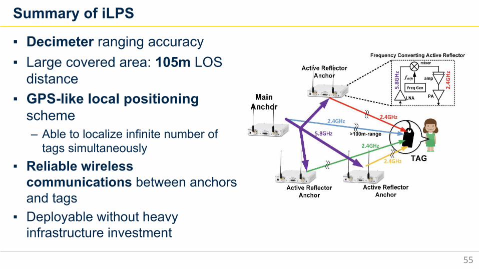
Summary of iLPS
▪ Decimeter ranging accuracy▪ Large covered area: 105m LOS
distance▪ GPS-like local positioning
scheme– Able to localize infinite number of
tags simultaneously ▪ Reliable wireless
communications between anchors and tags
▪ Deployable without heavy infrastructure investment
55
Research Scope▪ New Indoor RF Localization Solutions
– Year1: RF-Echo with custom ASIC tag– Year2: iLPS for simultaneous communication and localization– Year3: Sound-RF hybrid solution
▪ Application specific integrated circuit (ASIC) fabrication– Year1: Low power active reflection tag ASIC– Year2 and 3: Low power processor for software-defined radio ASIC
• Wireless communication (WiFi, Bluetooth, Zigbee, proprietary)• RF localization• Deep learning neural network processing for RF
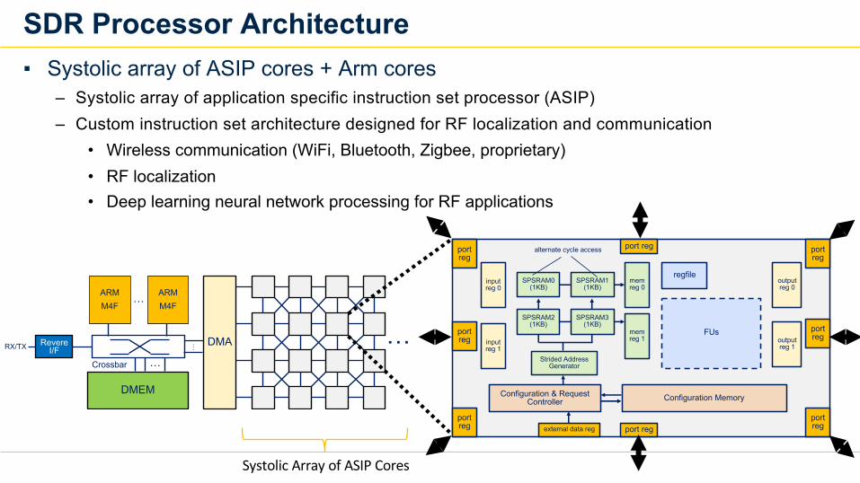
SDR Processor Architecture▪ Systolic array of ASIP cores + Arm cores
– Systolic array of application specific instruction set processor (ASIP)– Custom instruction set architecture designed for RF localization and communication
• Wireless communication (WiFi, Bluetooth, Zigbee, proprietary)• RF localization• Deep learning neural network processing for RF applications
Systolic Array of ASIP Cores
ARMM4F
…
ARMM4F
DMEM
…
Crossbar
Revere I/FRX/TX
…
DMA…
SPSRAM1 (1KB)
mem reg 0
mem reg 1
FUs
regfileinputreg 0
inputreg 1
outputreg 0
outputreg 1
port reg
port reg
port reg
port reg
port reg
port reg
port reg
port reg
Strided Address Generator
Configuration MemoryConfiguration & Request Controller
SPSRAM0 (1KB)
SPSRAM3 (1KB)
SPSRAM2 (1KB)
alternate cycle access
external data reg
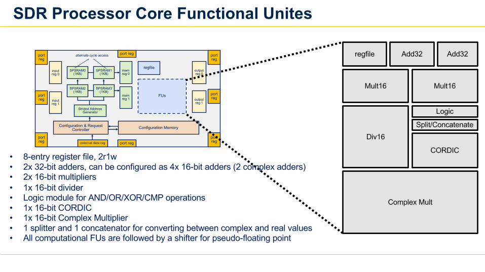
SDR Processor Core Functional Unites
SPSRAM1 (1KB)
mem reg 0
mem reg 1
FUs
regfileinputreg 0
inputreg 1
outputreg 0
outputreg 1
port reg
port reg
port reg
port reg
port reg
port reg
port reg
port reg
Strided Address Generator
Configuration MemoryConfiguration & Request Controller
SPSRAM0 (1KB)
SPSRAM3 (1KB)
SPSRAM2 (1KB)
alternate cycle access
external data reg
regfile Add32 Add32
Mult16 Mult16
Div16
Logic
CORDIC
Complex Mult
Split/Concatenate
• 8-entry register file, 2r1w• 2x 32-bit adders, can be configured as 4x 16-bit adders (2 complex adders)• 2x 16-bit multipliers• 1x 16-bit divider• Logic module for AND/OR/XOR/CMP operations• 1x 16-bit CORDIC• 1x 16-bit Complex Multiplier• 1 splitter and 1 concatenator for converting between complex and real values• All computational FUs are followed by a shifter for pseudo-floating point
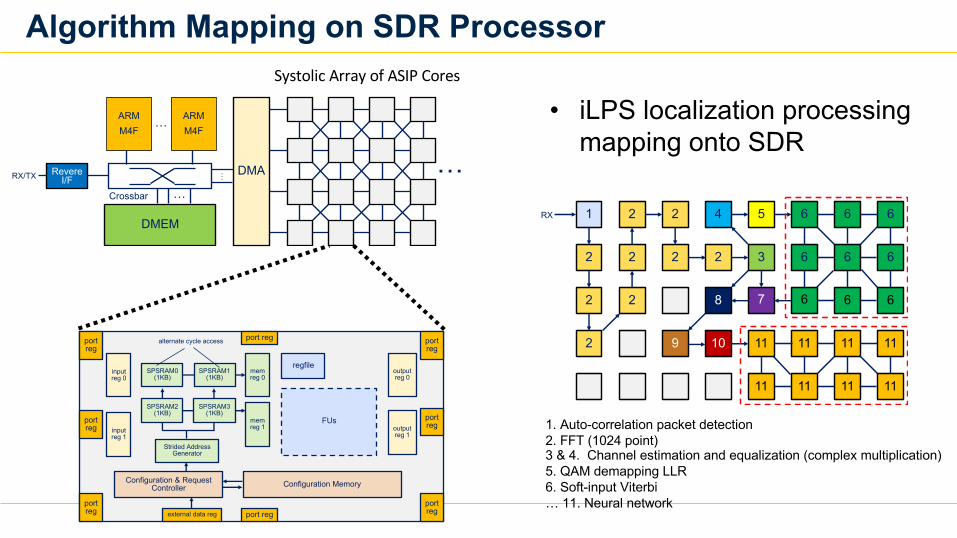
Algorithm Mapping on SDR Processor
1RX 2 2 4 5 6 6 6
66632222
2
2
2 8 7 6 6 6
11111111109
11 11 11 11
1. Auto-correlation packet detection2. FFT (1024 point)3 & 4. Channel estimation and equalization (complex multiplication)5. QAM demapping LLR6. Soft-input Viterbi… 11. Neural network
Systolic Array of ASIP Cores
ARMM4F
…
ARMM4F
DMEM
…
Crossbar
Revere I/FRX/TX
…
DMA…
• iLPS localization processing mapping onto SDR
SPSRAM1 (1KB)
mem reg 0
mem reg 1
FUs
regfileinputreg 0
inputreg 1
outputreg 0
outputreg 1
port reg
port reg
port reg
port reg
port reg
port reg
port reg
port reg
Strided Address Generator
Configuration MemoryConfiguration & Request Controller
SPSRAM0 (1KB)
SPSRAM3 (1KB)
SPSRAM2 (1KB)
alternate cycle access
external data reg
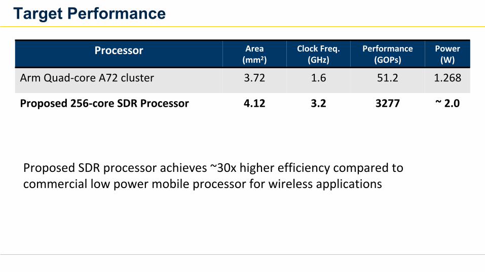
Target Performance
Processor Area (mm2)
Clock Freq. (GHz)
Performance(GOPs)
Power (W)
Arm Quad-core A72 cluster 3.72 1.6 51.2 1.268
Proposed 256-core SDR Processor 4.12 3.2 3277 ~ 2.0
Proposed SDR processor achieves ~30x higher efficiency compared to commercial low power mobile processor for wireless applications
Conclusion▪ New Indoor RF Localization Solutions
– Year1: RF-Echo with custom ASIC tag– Year2: iLPS for simultaneous communication and localization– Year3: Sound-RF hybrid solution
▪ Application specific integrated circuit (ASIC) fabrication– Year1: Low power active reflection tag ASIC– Year2 and 3: Low power processor for software-defined radio ASIC
• Wireless communication (WiFi, Bluetooth, Zigbee, proprietary)• RF localization• Deep learning neural network processing for RF

62
Thank you !

Get your hands on the tech!
Demos OpenBACK TOMORROW
8:00 AM
63
#PSCR2019


![StarFireTM: A Global SBAS for Sub-Decimeter Precise Point ... · [Hatch et al 2003]. ... GPS satellite when using the station elevation mask of ... A Global SBAS for Sub-Decimeter](https://img.pdfslide.us/doc/110x75/5c16718309d3f25e0b8c86d9/starfiretm-a-global-sbas-for-sub-decimeter-precise-point-hatch-et-al-2003.jpg)