Embed Size (px)
Citation preview

DECENTRALIZED SLIDING MODE CONTROL FOR AN
ELECTROHYDRAULIC ROBOT MANIPULATOR
HASZURAIDAH ISHAK
A project report submitted in partial fulfilment of the
requirements for a award of the degree of
Master of Engineering (Electrical-Mechatronics and Automatic Control)
Faculty of Electrical Engineering
Universiti Teknologi Malaysia
MAY 2007

iii
This thesis is especially dedicated to my dearest father, mother and family
for their love, blessing and encouragement ...

iv
ACKNOWLEDGEMENT
Alhamdulillah, I am greatly indebted to Allah SWT on His mercy and
blessing for making this project successful.
I would like to express my deepest gratitude and thanks to Professor Dr.
Johari Halim Shah Osman, my honourable supervisor, for his continuous guidance,
committed support and invaluable advice throughout my study.
I wish to thank Associate Professor Dr. Mohamad Noh Ahmad and
Associate Professor Dr. Yahaya Md Sam for their guidance and facilitation on the
Sliding Mode Control theory and the utilisation of Matlab / Simulink software.
I sincerely thank to all lecturers who have taught me, for the lesson that has
been delivered. Not to mention, to all my friends, thank you for sharing useful idea,
information and moral support during the course of study.
Last but not least, I would like to express my sincere appreciation and
gratitude to my parents, who are always there when it matters most.

v
PUBLICATION
The following paper, based on the work described in this thesis, has been submitted
to conference:
1. J.H.S Osman, H. Ishak. A Decentralized Sliding Mode Tracking Controller
for Hydraulic Robot Manipulators. The 1st International Conference on
Control, Instrumentation, and Mechatronics Engineering (CIM). 2007.
Johor, Malaysia. (Accepted for Oral Presentation and Publication).
2. S.Z Nordin, H. Ishak, J.H.S Osman. Sliding Mode Tracking Controller for
Hydraulic Manipulators with Numerical Analysis. 2ND International
Conference on Mathematical Sciences (ICoMS). 2007. Johor, Malaysia.
(Accepted for Oral Presentation and Publication).

vi
ABSTRACT
This thesis is concerned with the problems of modelling and controlling of a
3 DOF electrohydraulic robot manipulators. The control of electrohydraulic robot
manipulator is challenging due to the dependence of system parameters on variables
such as displacement and velocity, on the geometry and inertia of the links,
uncertainties associated with gravity, coriolis and centrifugal forces, variations in
payload handled by the manipulator, and environmental influences. To overcome
these problems, an integrated mathematical model of the 3 DOF electrohydraulic
robot manipulators is treated as a large-scale uncertain system models using the
known parameters of the robot. Decentralized control concept is used in this study
where the uncertain system is treated as large-scale system which composed of a set
of interconnected uncertain subsystems. A variable structure control (VSC) strategy
is utilized to overcome the inherent high nonlinearity in the system dynamics under
decentralized and centralized frameworks. In each of the approach, a variant of the
VSC known as the Sliding Mode Control (SMC) is adopted to ensure the stability of
the system dynamics during the sliding phase and to render that the system
insensitive to the parametric variations and disturbances. The performance and
robustness of the proposed controller is evaluated through computer simulation by
using Matlab and Simulink. The results proved that the controller has successfully
provided the necessary tracking control for the 3 DOF electrohydraulically driven
robot manipulator system.

vii
ABSTRAK
Tesis ini bertujuan untuk mengenengahkan model matematik dan teknik
kawalan bagi robot berkuasa hidro. Pengawalan robot berkuasa hidro adalah lebih
rumit disebabkan sifat sambungan mekanikal dan motornya yang tidak linear,
parameter yang berubah-ubah, ketidaktentuan beban dan kesan perangkai. Untuk
mengatasi masalah ini, model bersepadu untuk tiga darjah kebebasan robot berkuasa
hidro ditukar menjadi suatu sistem berskala besar tak pasti berdasarkan kepada had-
had parameter sistem. Reka bentuk kawalan berasaskan kepada pendekatan kawalan
ternyahpusat digunakan dalam simulasi ini dengan menganggap sistem robot sebagai
suatu sistem berskala besar, yang mempunyai model bersepadu yang boleh
dipecahkan menjadi beberapa sub-sistem yang saling terhubungkait. Strategi
kawalan struktur berubah (VSC) diadaptasi untuk mengatasi ciri-ciri rumit yang
terdapat dalam robot berkuasa hidro menggunakan konsep ternyahpusat dan sepusat.
Didalam setiap pendekatan ini, dua pengawal penjejakan menggunakan konsep
kawalan gelincir telah dicadangkan, di mana pengawal pertama menggunakan
konsep sepusat, manakala pengawal kedua menggunakan konsep ternyahpusat
Kawalan ragam gelincir (SMC) iaitu variasi daripada kawalan struktur berubah telah
dipilih untuk memastikan kestabilan sistem semasa fasa gelincir tanpa dipengaruhi
parameter yng berubah-ubah dan ketidaktentuan beban. Pencapaian kaedah ini
dinilai melalui simulasi komputer. Keputusan membuktikan bahawa, strategi
kawalan ini berjaya dalam membekalkan kawalan laluan/ trajektori yang diperlukan
untuk sistem lengan robot berkuasa hidro.
viii
CONTENTS
CHAPTER TITLE PAGE
TITLE
DECLARATION ii
DEDICATION iii
ACKNOWLEDGEMENT iv
PUBLICATION v
ABSTRACT vi
ABSTRAK vii
CONTENTS viii
LIST OF TABLES xi
LIST OF FIGURES xii
LIST OF SYMBOLS xviii
LIST OF ABBREVIATIONS xx
1 INTRODUCTION 1
1.1 Robot Manipulator System 1
1.2 Electrohydraulic Robot Manipulator 4
1.3 Research Objective 9
1.4 Scope of Research 10
1.5 Research Methodology 10
1.6 Structure and Layout of Thesis 12

ix
2 MATHEMATICAL MODELING OF ELECTROHYDRAULIC
ROBOT MANIPULATOR 14
2.1 Introduction 14
2.2 Dynamic Equation and State Space Representation
of Electrohydraulic Actuator 15
2.3 Dynamic Equation of Robot Manipulator
Mechanical Linkage 21
2.4 Integrated Dynamic Model of the Electrohydraulic
Robot Manipulator 23
2.5 Dynamic Model of 3 DOF Electrohydraulic
Robot Manipulators 26
2.5.1 Dynamic Equation of the Electrohydraulic
Motors for the 3 DOF Robot Manipulator 28
2.5.2 Dynamic Equation of 3 DOF Robot
Manipulator Mechanical Linkage 31
2.5.3 Integrated Dynamic Model of the Three DOF
Electrohydraulic Robot Manipulator 35
2.6 Summary 40
3 DECENTRALIZED SLIDING MODE
CONTROLLER DESIGN 42
3.1 Introduction 42
3.2 Decentralized Sliding Mode Control Strategies 43
3.3 Electrohydraulic Robot Manipulator as a
Large-Scale Uncertain System 45
3.4 Problem Formulation for Decentralized SMC 52
3.4.1 System Dynamics during Sliding Mode 54
3.4.2 Sliding Mode Tracking Controller Design 55
3.5 Summary 57

x
4 SIMULATION 58
4.1 Introduction 58
4.2 Trajectory Generation 58
4.3 Simulation Study 60
4.4 Controller Parameters Selection 61
4.5 Tuning Algorithm 62
4.6 Simulation using Centralized Sliding Mode
Controller 64
4.61 Numerical Computation and Selection
of Controller Parameters 64
4.7 Simulation Decentralized Sliding Mode
Controller 72
4.71 Numerical Computation and Selection
of Controller Parameters 72
4.7.2 Comparison of the Centralized SMC &
Decentralized SMC 80
4.7.3 Effect of Load Variation 87
4.7.4 Effect of the Controller Parameter 90
4.7.5 Effect of Sliding Surface Constant, C 97
4.7.6 Effect of Sampling Time 102
4.7.7 Effect of Closed-loop Poles 106
4.7.8 Control Input Chattering Suppression 110
4.6 Summary 115
5 CONCLUSION 117
5.1 Conclusion 117
5.2 Suggestion For Future Work 118
REFERENCES 120
xi
LIST OF TABLES
TABLE NUMBER TITLE PAGE
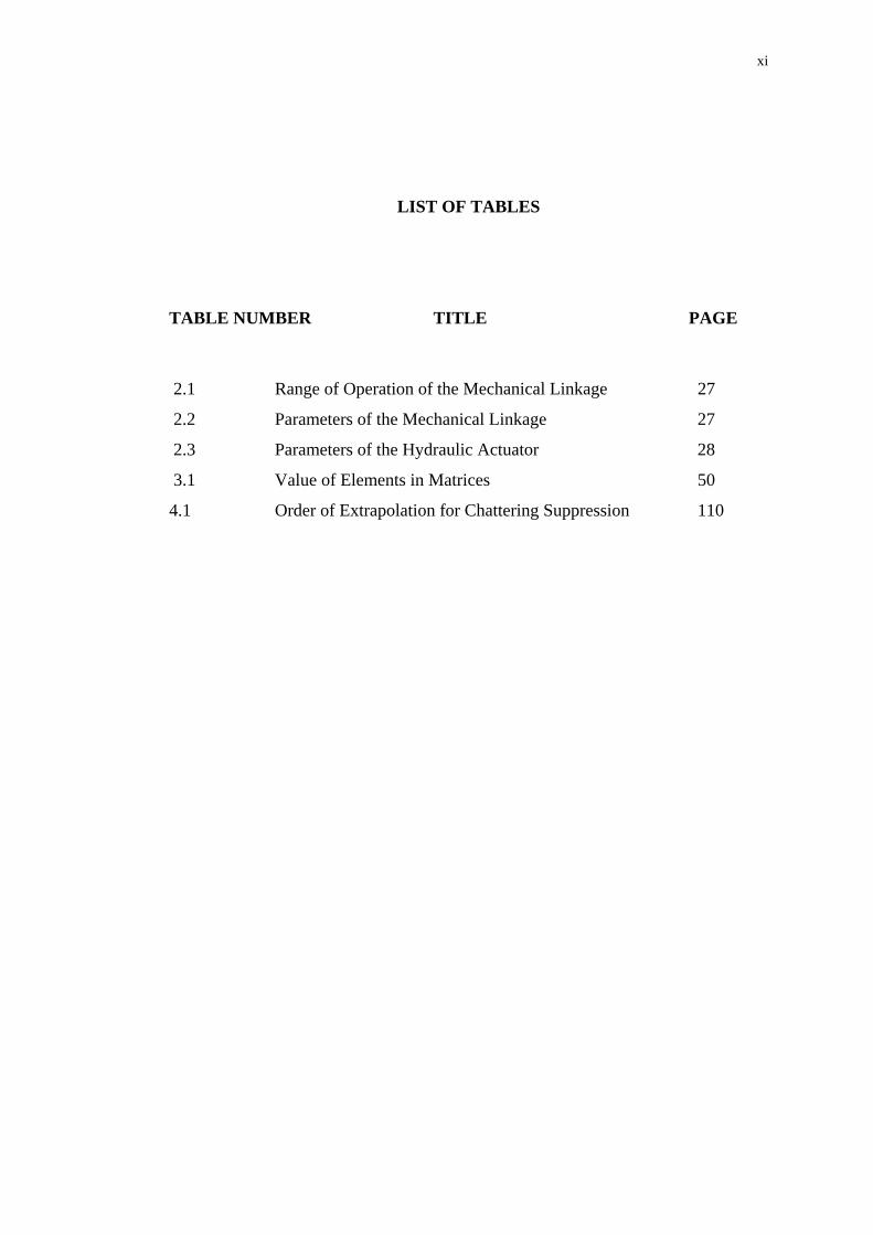
2.1 Range of Operation of the Mechanical Linkage 27
2.2 Parameters of the Mechanical Linkage 27
2.3 Parameters of the Hydraulic Actuator 28
3.1 Value of Elements in Matrices 50
4.1 Order of Extrapolation for Chattering Suppression 110
xii
LIST OF FIGURES
FIGURE NUMBER TITLE PAGE
1.1 Schematic diagram of a hydraulic system and its
components 2
1.2 Schematic diagram of a spool valve in a neutral position 3
2.1 Physical Model of an Electrohydraulic Servo Control
System 16
2.2 Schematic diagram of the Gear Train Connecting the
Motor and the Load 18
2.3 Three DOF Hydraulically Driven Robot Manipulator 26
4.1 Desired Joint Position Profile 59
4.2 Desired Joint Velocity Profile 60
4.3 Simulation Flow Chart 61
4.4 Joint 1 tracking response (angle) using centralized SMC
tracking controller 66
4.5 Joint 2 tracking response (angle) using centralized SMC
tracking controller 66
4.6 Joint 3 tracking response (angle) using centralized SMC
tracking controller 67
4.7 Joint 1 tracking response (velocity) using centralized
SMC tracking controller 2 67
4.8 Joint 2 tracking response (velocity) using centralized
SMC tracking controller 2 68
4.9 Joint 3 tracking response (velocity) using centralized
SMC tracking controller 2 68
4.10 Joint 1 control input using centralized SMC
tracking controller 69

xiii
4.11 Joint 2 control input using centralized SMC
tracking controller 69
4.12 Joint 3 control input using centralized SMC
tracking controller 70
4.13 Joint 1 sliding surface using centralized SMC
tracking controller 70
4.14 Joint 2 sliding surface using centralized SMC
tracking controller 71
4.15 Joint 3 sliding surface using centralized SMC
tracking controller 71
4.16 Joint 1 tracking response (angle) using decentralized
SMC tracking controller 74
4.17 Joint 2 tracking response (angle) using decentralized
SMC tracking controller 74
4.18 Joint 3 tracking response (angle) using decentralized
SMC tracking controller 75
4.19 Joint 1 tracking response (velocity) using decentralized
SMC tracking controller 75
4.20 Joint 2 tracking response (velocity) using decentralized
SMC tracking controller 76
4.21 Joint 3 tracking response (velocity) using decentralized
SMC tracking controller 76
4.22 Joint 1 control input using decentralized SMC
tracking controller 77
4.23 Joint 2 control input using decentralized SMC
tracking controller 77
4.24 Joint 3 control input using decentralized SMC
tracking controller 78
4.25 Joint 1 sliding surface using decentralized SMC
tracking controller 78
4.26 Joint 2 sliding surface using decentralized SMC
tracking controller 79
4.27 Joint 3 sliding surface using decentralized SMC
tracking controller 79

xiv
4.28 Joint 1 tracking error (angle, 0kg) using Centralized
and Decentralized SMC 81
4.29 Joint 2 tracking error (angle, 0kg) using Centralized
and Decentralized SMC 81
4.30 Joint 3 tracking error (angle, 0kg) using Centralized
and Decentralized SMC 82
4.31 Joint 1 tracking error (velocity, 0kg) using Centralized
and Decentralized SMC 82
4.32 Joint 2 tracking error (velocity, 0kg) using Centralized
and Decentralized SMC 83
4.33 Joint 3 tracking error (velocity, 0kg) using Centralized
and Decentralized SMC 83
4.34 Joint 1 tracking error (angle, 10kg) using Centralized
and Decentralized SMC 84
4.35 Joint 2 tracking error (angle, 10kg) using Centralized
and Decentralized SMC 84
4.36 Joint 3 tracking error (angle, 10kg) using Centralized
and Decentralized SMC 85
4.37 Joint 1 tracking error (velocity, 10kg) using Centralized
and Decentralized SMC 85
4.38 Joint 2 tracking error (velocity, 10kg) using Centralized
and Decentralized SMC 86
4.39 Joint 3 tracking error (velocity, 10kg) using Centralized
and Decentralized SMC 86
4.40 Joint 1 tracking error (angle) with mass variation 87
4.41 Joint 2 tracking error (angle) with mass variation 88
4.42 Joint 3 tracking error (angle) with mass variation 88
4.43 Joint 1 tracking error (velocity) with mass variation 89
4.44 Joint 2 tracking error (velocity) with mass variation 89
4.45 Joint 3 tracking error (velocity) with mass variation 90
4.46 Joint 1 tracking response (angle) with unsatisfied
controller parameter 91
4.47 Joint 2 tracking response (angle) with unsatisfied
controller parameter 92

xv
4.48 Joint 3 tracking response (angle) with unsatisfied
controller parameter 92
4.49 Joint 1 tracking error (velocity) with unsatisfied
controller parameter 93
4.50 Joint 2 tracking error (velocity) with unsatisfied
controller parameter 93
4.51 Joint 3 tracking error (velocity) with unsatisfied
controller parameter 94
4.52 Joint 1 control input with unsatisfied
controller parameter 94
4.53 Joint 2 control input with unsatisfied
controller parameter 95
4.54 Joint 3 control input with unsatisfied
controller parameter 95
4.55 Joint 1 sliding surface with unsatisfied
controller parameter 96
4.56 Joint 2 sliding surface with unsatisfied
controller parameter 96
4.57 Joint 3 sliding surface with unsatisfied
controller parameter 97
4.58 Joint 1 tracking error (angle) with different
sliding surfaces 99
4.59 Joint 2 tracking error (angle) with different
sliding surfaces 99
4.60 Joint 3 tracking error (angle) with different
sliding surfaces 100
4.61 Joint 1 tracking error (velocity) with different
sliding surfaces 100
4.62 Joint 2 tracking error (velocity) with different
sliding surfaces 101
4.63 Joint 3 tracking error (velocity) with different
sliding surfaces 101
4.64 Joint 1 tracking response (angle) with different
sampling time 103
xvi
4.65 Joint 2 tracking response (angle) with different
sampling time 103
4.66 Joint 3 tracking response (angle) with different
sampling time 104
4.67 Joint 1 tracking response (velocity) with different
sampling time 104
4.68 Joint 2 tracking response (velocity) with different
sampling time 105
4.69 Joint 3 tracking response (velocity) with different
sampling time 105
4.70 Joint 1 tracking error (angle) with different
closed-loop poles 107
4.71 Joint 2 tracking error (angle) with different
closed-loop poles 107
4.72 Joint 3 tracking error (angle) with different
closed-loop poles 108
4.73 Joint 1 tracking error (velocity) with different
closed-loop poles 108
4.74 Joint 2 tracking error (velocity) with different
closed-loop poles 109
4.75 Joint 3 tracking error (velocity) with different
closed-loop poles 109
4.76 Control input for each joint using Solver Ode14x Set 1 111
4.77 Control input for each joint using Solver Ode14x Set 2 111
4.78 Control input for each joint using Solver Ode14x Set 3 112
4.79 Joint 1 tracking error (angle) using variation order of
Solver Ode14x 113
4.80 Joint 2 tracking error (angle) using variation order of
Solver Ode14x 113
4.81 Joint 3 tracking error (angle) using variation order of
Solver Ode14x 113
4.82 Joint 1 tracking error (velocity) using variation order of
Solver Ode14x 114

xvii
4.83 Joint 2 tracking error (velocity) using variation order of
Solver Ode14x 114
4.84 Joint 3 tracking error (velocity) using variation order of
Solver Ode14x 115

xviii
LIST OF SYMBOLS
SYMBOL DESCRIPTION
1. UPPERCASE
A(*,*) system matrix for the integrated direct drive robot arm
ΔA(*,*) matrix representing the uncertainties in the system matrix
B(*,*) input matrix for the intagrated direct drive robot arm
ΔB(*,*) matrix representing the uncertainties in the input matrix
Bmi viscous damping coefficient of ith actuator
C constant matrix of the PI sliding surface
Dmi volumetric displacement of ith actuator
Jmi ith motor inertia
Ii moment of inertia of ith link
Kqi flow gain in ith actuator
Kti total leakage coefficient in ith actuator
Kvi servo valve gain
N number of joints
Psi supply pressure in ith actuator )(tSδ a continuous function used to eliminate chattering
iLT load torque for ith motor
U(*) N x 1 control input vector for a N DOF robot arm
Vti
total compressed volume in ith actuator
X(*) state vector for the integrated electrohydraulic manipulator
Z(*) error state vector between the actual and the desired states of
the overall system
(*)T transpose of (*)

xix
||(*)T|| Euclidean norm of (*)
2. LOWERCASE
aij ijth element of the integrated system matrix A(*,*)
bij ijth element of the integrated input matrix B(*,*)
g gravity acceleration (m.s2)
li length of the ith manipulator link (m)
mi mass of the ith manipulator link (kg)
t time (s)
3. GREEK SYMBOLS
α norm bound of continuous function H(*)
β norm bound of continuous function E(*)
eiβ
effective bulk modulus in ith actuator
θ& joint displacement (rad)
θ&& joint velocity (rad/s)
θ&&& joint acceleration (rad/s2)
dθ& desired joint angle (rad)
dθ&& desired joint velocity (rad/s)
dθ&&& desired joint acceleration (rad/s2)
σ Integral sliding manifold
τ time interval for arm to travel from a given initial position to a final
desired position (seconds)
xx
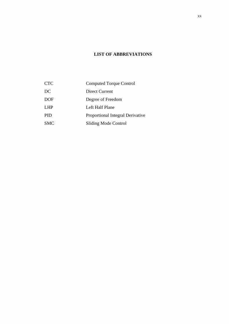
LIST OF ABBREVIATIONS
CTC Computed Torque Control
DC Direct Current
DOF Degree of Freedom
LHP Left Half Plane
PID Proportional Integral Derivative
SMC Sliding Mode Control

1
CHAPTER 1
INTRODUCTION
1.1 Robot Manipulator System
Industrial robots have gained a wide popularity as essential components for
the realization of automated manufacturing systems. Reduction of manufacturing
costs, increase of productivity, improvement of product quality standards and last
but not least, the possibility of eliminating harmful or alienating tasks for the human
operator in manufacturing system, represent the main factors that have spearhead the
spreading of robotics technology in a wide range of applications in manufacturing
industry [1].
An industrial robot is constituted by a mechanical structure or manipulator
that consists of sequence of rigid bodies (links) connected by means of articulation
whether revolute or prismatic joints and this manipulator is characterized by an arm
that ensures mobility, a wrist that confers dexterity and an end effector that performs
the task required of the robot, actuators that set the manipulator in motion through
actuation of the joints while the motors employed are typically electric and
hydraulic, and occasionally pneumatic, sensors that measure the status of the
manipulator and if necessary the status of the environment and a control system
(computer) that enables control and supervision of manipulator motion [1].
Although electrically driven robots are widely used in an increasing number
of applications, there are many industrial tasks where hydraulic actuators can be
used advantageously. For special applications such as for very large robots and civil

2
service robots, hydraulic actuator may be an appropriate choice [2]. Machinery in
construction, forming, mining, forestry industry, heavy load motion control and
mobile equipment applications as well as large flight simulators take the advantage
of the high power to weight ratio, possible speed reversals and continuous operation,
the stiffness and short response time of hydraulic drives.
Electrohydraulic system uses low power electrical signals for precisely
controlling the movements of large power pistons and motors. The interface between
the electrical equipment and the hydraulic (power) equipment is called ‘hydraulic
servo valve’. These valves used in the system must respond quickly and accurately.
A schematic diagram of a typical hydraulic system is shown in Figure 1.1.
Figure 1.1: Schematic diagram of a hydraulic system and its components
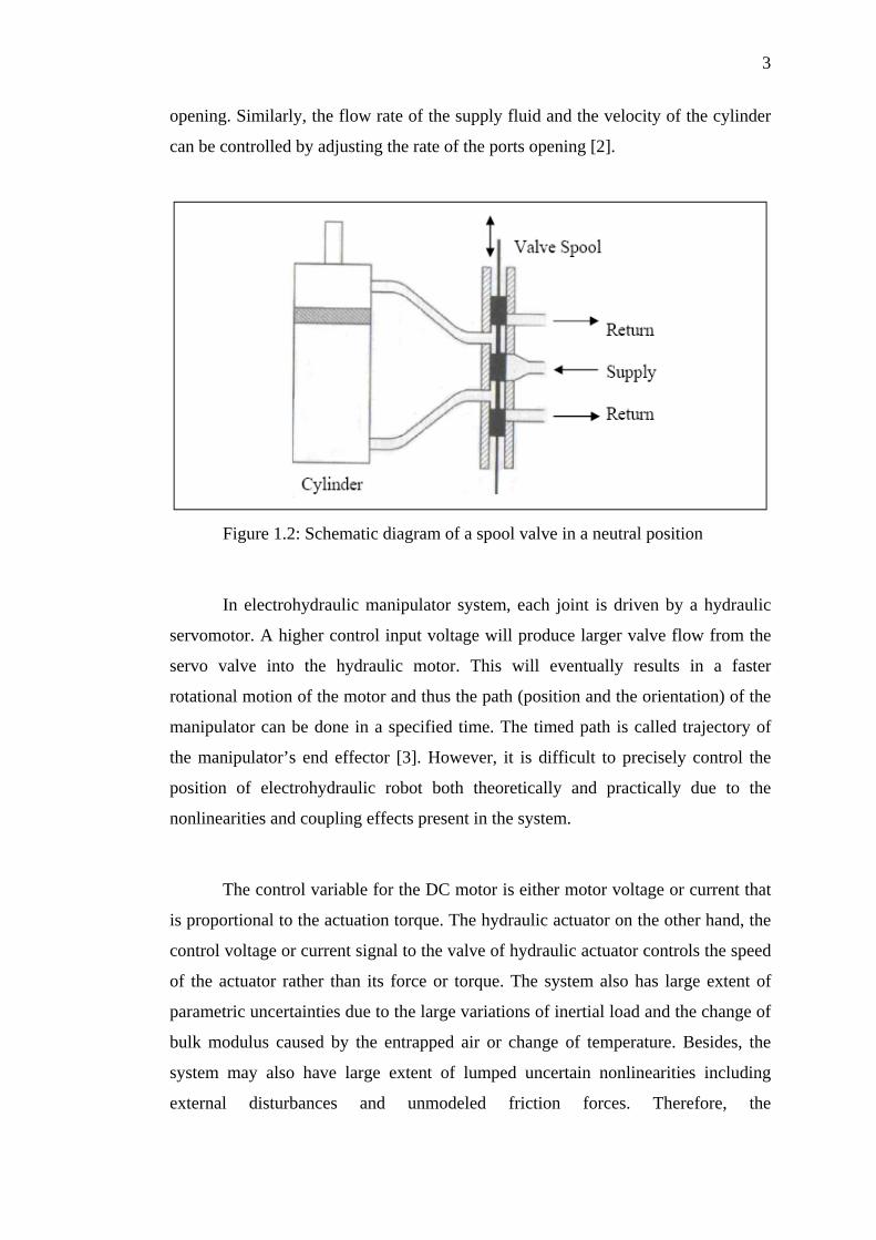
A servo valve is created when a servomotor is attached to the spool valve
and the servo valve. The servo valve together with the hydraulic actuator will form
the hydraulic servomotor. A simple movement of the spool valve controls the
motion of the actuator. As the spool moves up and down, it opens the supply and
returns to the port through which the fluid travels to the cylinder or return to the
reservoir as shown in Figure 1.2. The amount of the supply fluid and the
displacement of the cylinder can be controlled by adjusting the size of these ports
3
opening. Similarly, the flow rate of the supply fluid and the velocity of the cylinder
can be controlled by adjusting the rate of the ports opening [2].
Figure 1.2: Schematic diagram of a spool valve in a neutral position
In electrohydraulic manipulator system, each joint is driven by a hydraulic
servomotor. A higher control input voltage will produce larger valve flow from the
servo valve into the hydraulic motor. This will eventually results in a faster
rotational motion of the motor and thus the path (position and the orientation) of the
manipulator can be done in a specified time. The timed path is called trajectory of
the manipulator’s end effector [3]. However, it is difficult to precisely control the
position of electrohydraulic robot both theoretically and practically due to the
nonlinearities and coupling effects present in the system.
The control variable for the DC motor is either motor voltage or current that
is proportional to the actuation torque. The hydraulic actuator on the other hand, the
control voltage or current signal to the valve of hydraulic actuator controls the speed
of the actuator rather than its force or torque. The system also has large extent of
parametric uncertainties due to the large variations of inertial load and the change of
bulk modulus caused by the entrapped air or change of temperature. Besides, the
system may also have large extent of lumped uncertain nonlinearities including
external disturbances and unmodeled friction forces. Therefore, the
4
electrohydraulically driven revolute robot manipulator dynamics are more complex
than electrically driven manipulator dynamics. All of these factors make the
modeling and control of such system a challenging task [4].
In all industrial robot applications, completion of a generic task requires the
execution of a specific motion that prescribed by the desired path trajectory and
performance. However, when faster trajectories are demanded, the performance of
the manipulator will be worst. Therefore, the correct execution is entrusted to the
control system which shall provide the joint actuators of the manipulator with the
command consistent with the desired motion trajectory. Thus, an accurate analysis
of the characteristics of the manipulator dynamics is therefore a necessary premise
to finding motion control strategies. In general, motion control problem consists of
obtaining the dynamics model of the electrohydraulic robot manipulator in which
these models will be used to determine the control laws or strategies to achieve the
desired system response and performance.
1.2 Electrohydraulic Robot Manipulator
Nowadays, hydraulic robots are widely used in the construction and mining
industries. However, majority of earlier work in the design of the control laws for
manipulators deal with electrically actuated manipulators. In terms of hydraulic
actuators, comparatively less work has been done [5]. However, by taking the
dynamics of the actuator alone is not sufficient to represent the dynamic of hydraulic
manipulator, since it does not take into account the arm dynamic forces such as the
inertia forces, the coriolis and centrifugal effects and also the gravity effects that will
affect the performance of the controller. Tracking performance of the system can be
improved by implementing mechanical linkage dynamic model in the controller
design since it is part of the overall control system. This approach has been
successfully shown in many electrical robots in the past [6].

5
[7] has used 6 DOF hydraulic robot and the models incorporate manipulator
dynamics. The limitation with this project is that it did not include the hydraulic
motor nonlinear spring stiffness, viscous damping and inertia. Same goes with [8]
who has incorporated manipulator dynamics in developing 2 DOF hydraulic robot
arm models, but the hydraulic motor nonlinear spring stiffness, viscous damping and
inertia are not taken into account in the design. [9] on the other hand, have used
hydraulic cylinders with the application to robot manipulators. The problem with the
study is that it did not incorporate the mechanical linkage dynamics in the design
model.
[5] has incorporated both rigid body dynamics and hydraulic actuator
dynamics into the design. However, the mathematical model presented was not in
state-space form. For some recent development on mathematical model derivation of
this type of manipulator, [10] has developed the mathematical model in state-space
form for the electrohydraulic robot manipulator that integrated both the manipulator
dynamics and hydraulic actuator dynamics including the hydraulic motor nonlinear
spring stiffness, viscous damping and inertia.
The mathematical model derived in [10] will be used in this project to
synthesize different control laws in providing the trajectory tracking control of the 3
DOF electrohydraulically driven revolute robot manipulator.
The robot control problem revolves around the computation of the required
actuator inputs in order to maintain the dynamic response of manipulator in
accordance with the desired response and performance. This control problem will
become complex due to the nonlinear dependence of system parameters on variables
such as displacement and velocity, on the geometry and inertia of the links,
uncertainties associated with gravity, coriolis and centrifugal forces, variations in
payload handled by the manipulator, and environmental influences.
In classical control theory, it is assumed that the control actions are
undertaken by a single controller that has all the available information about the
6
system and treat each joint of the manipulator as a simple linear servomechanism as
in most of industrial robots, whereby the simple controller like Independent Joint
Control (IJC), proportional plus derivative (PD), or proportional plus integral plus
derivative (PID) controllers are adopted. In these methods, the nonlinear, coupled
and time-varying dynamics of the mechanical linkage of the robot manipulator have
been excluded and completely ignored, or assumed as disturbances. Manipulators
that have been controlled by this method usually move at slow speeds with
unnecessary vibrations. In general, the method is only suitable for relatively slow
manipulation and limited precision tasks [11]. However, when the manipulator joints
are moving simultaneously and at high speed, the nonlinear coupling effects and the
interaction forces between the manipulator links may affect the performance of the
overall system and increase the tracking error. The disturbances and uncertainties
such as variable payload in a task cycle may also reduce the tracking quality of the
robot manipulator system [12].
Therefore, control strategies for high speed robotic system are of great
interest for both industrial and academic fields, whereby various advanced and
sophisticated control techniques have been proposed by numerous researchers in
providing the necessary tracking trajectory of robot manipulator and at the same
time guaranteeing the stability of the system. In general, these strategies can be
divided into two categories; the non-model based or usually known as Artifical
Intelligence approaches and model based approaches. While for the structures of
these controllers can be grouped into three categories; the centralized, decentralized,
and multilevel hierarchical. For the model based approaches, among the major
control approaches considered in the literature for the uncertainties nonlinear
systems are the Adaptive Control method [13], Lyapunov based control and
Variable Structure Control [14]. While for the non-model based approaches, where
the knowledge of the mathematical model is not needed, Fuzzy Logic system,
Genetic Algorithm and Neural Networks controls have become important research
topics [15].
In [8], PID and Computed Torque Control (CTC) strategies have been
implemented for the hydraulic robot and the performance of both methods did not

7
give satisfactory results. As mentioned earlier, the limitation with PID controllers is
that they are not meant for high speed robots and in situations that require precise
trajectory tracking. While for the CTC, it only can be applied to robots allowing
joint torque control. Moreover, the problem with CTC is essentially based on exact
robot arm dynamic model; the explicit use of an incorrect robot model will affect the
performance of control. He further synthesized the Kinematic Compensation Control
integrating a feedforward kinematic compensation and conventional regulatory
control techniques. Even though the system shows good experimental result, it still
lacks mathematical stability proof.
[16] has proposed a link-space pressure feedback controller for Stewart type
hydraulic manipulator. However, this approach lacks stability proofs that are
important from both theoretical and implementations points of view. [17] has
developed a generalized predictive control algorithm for hydraulic control system
but the limitation of this approach is that it relies heavily on online parameter
estimation and consequently, is computationally expensive. [18] on the other hand,
have adopted a Lyapunov based Model-based Adaptive Control for hydraulic
manipulator. Even though the technique possesses mathematical stability proof but it
needs persistent excitation and pressure feedback. A strategy based on Backstepping
approach has been developed by [19] to provide necessary position tracking for the
hydraulic robot. However, the proposed strategy also relies on online computation
for converting into task-space coordinates. Furthermore, it is said to be sensitive to
sensor noise, hence high-quality measurements are needed. To overcome this
drawback is by introducing heuristic limitation of time derivatives in the control law
so that the influence of sensor noise in the simulations reduces significantly, but may
deteriorate the control performance.
Non-adaptive control techniques such as computed torque methods and
optimal control have serious disadvantages, namely complex controller structure,
excessive on-line computation, and sensitivity to uncertainties and nonlinearities in
the system. These difficulties become more complicated by their being centralized
approaches. Adaptive control methods tackle the robot control problem fairly
effective, but the controller is greatly complicated. In much of the works on adaptive

8
control of manipulators, the justification for this added complexity is not addressed
[20]. Despite the fact that the centralized approaches have attained significant
achievements to improve the tracking performance of robots, but when the degree of
freedom (D.O.F) of robots is large, they stumble upon time consuming computations
and complexity of the controller structure. Furthermore, very few results could be
transferred into practice due to the high implementation cost. Besides, the
centralized approach treats the robot manipulator as a single entity plant, which is
unfavorable and impractical for implementation and maintenance of the controllers
[21]. Therefore control methods that reduce these problems by changing the problem
to control smaller scale subsystems by using the decentralized controllers have the
advantage of computation simplicity and low-cost hardware setup. For this reason,
improving the performance of the trajectory tracking problem of robot manipulator
through decentralized control is an interesting topic.
Variable Structure Control utilizes a high-speed switching control law to
drive the nonlinear plant’s state trajectory onto a specified and user-chosen surface
in the state space and to maintain the plant’s state trajectory on this surface for all
subsequent time [22]. This property of remaining on the switching surface once
intercepted is called a sliding mode. The plant dynamics will be restricted to this
surface to represent the controlled system’s behavior. Hence, it is suitable for
complex systems and is insensitive to parameters variations and uncertainties. SMC is
particularly well suited for the manipulator control problem for the following
reasons. First, the application of SMC does not require an exact knowledge of the
system dynamics, provided there is no un-modeled structural uncertainty. This
property is desirable since the complexity of the manipulator dynamics makes the
exact calculation of the dynamics infeasible if not impossible. Second, when the
SMC is applied, the performance of the system can be made insensitive to bounded
disturbances. This property is important in rejecting effects due to the Coulomb and
viscous frictions. It is also important when the manipulator is carrying payloads
because the payload exerts at the robot end-effector can be translated into forces or
disturbances at each of the joints. Thus, the application of the SMC technique results
in a performance that is robust with respect to disturbances and modeling errors,
while provides accurate tracking [21].

9
This project will extend the control strategies proposed in controlling two
coupled pendulums in [23] to provide trajectory tracking control of a three DOF
electrohydraulically driven revolute robot manipulator. The approach stabilizes a
system through a fast switching global control to render that the system to behave as
a second linear time invariant system which can be chosen to be stable. This method
incorporated the ideas of variable structure system with the technique of pole
placement in a decentralized nature. This is done by constructing a decentralized
sliding mode controller which will force the original nonlinear interconnected
uncertain subsystems to behave as a second linear interconnected uncertain
subsystem which has had its pole placed in the left half of the s-plane by pole
placement method.
1.3 Research Objective
The objectives of this project are:
i) To decompose the 3 degree of freedom (DOF) electrohydraulic robot
manipulator into interconnected uncertain subsystems;
ii) To design a decentralized robust controller based on Sliding Mode Control
(SMC) for the 3 degree of freedom (DOF) electrohydraulic robot
manipulator;
iii) To evaluate the performance of the system based on the proposed controller
and to compare the performance of the decentralized robust controller with a
centralized robust controller.

10
1.4 Scope of Research
The scope of work for this project includes:
i) To decompose the integrated nonlinear dynamic model of the 3 DOF
revolute electrohydraulic robot manipulator as described in [10] into a set of
interconnected subsystem by treating it as a large-scale system. The
interconnected model will be transformed into interconnected uncertain
subsystems models using the known parameters of the robot;
ii) To synthesize a decentralized tracking trajectory controller based on a
variant of the VSC approach, which is the SMC for large-scale uncertain
system. This proposed controller will be applied to the 3 DOF
electrohydraulically driven revolute robot manipulator models developed in
part (i);
iii) A centralized tracking trajectory controller will be designed based on the
deterministic approach for an uncertain system, where the transformation-
free SMC will be utilized;
iv) Simulation studies will be done to investigate the performance of the
proposed controller and the effectiveness of the decentralized SMC as
compared to the centralized SMC in providing the necessary position
tracking control for the system. These will be done using SIMULINK and
MATLAB 7.0.
1.5 Research Methodology
The research work is undertaken in the following three developmental stages:
a) Development of an interconnected uncertain system models of a 3 DOF
revolute hydraulic robot manipulator. The steps taken in this stage are:

11
i) Conduct literature review on the existing electrohydraulic robot
manipulator mathematical model in order to understand the
dynamics behavior of the system. Based on the information
obtained, the integrated model will be decomposed into three
interconnected subsystems in order to apply the decentralized
tracking controller;
ii) Conduct literature review on the existing techniques for
decomposing the system into interconnected uncertain
subsystems.
b) Application of a decentralized robust controller based on VSC technique to
the robotic system. The steps taken in this stage are:
i) Conduct literature review on the existing control technique for
robotic systems;
ii) Conduct literature review on the existing robust control technique
based on decentralized Sliding Mode Control algorithm;
iii) Synthesize the decentralized SMC technique cited from [23] to
the robotic system. The procedures performed in this stage are:
• Decomposition of the complete model into an large-scale
uncertain model
• Definition of each local sliding surface
• Determination of the system dynamics during Sliding Mode
• Establishment of the final control law for each subsystem
c) Perform computer simulation of the proposed controller by using MATLAB
and SIMULINK to investigate the effectiveness of the decentralized SMC as
compared to a centralized SMC.

12
1.6 Structure and Layout of Thesis
This report is organized into five chapters. In Chapter 2, the formulation of
the mathematical modeling of the integrated electrohydraulic robot manipulator, in
which, first, a general dynamic model of a hydraulic actuator dynamics and a rigid
manipulator link are described separately. Then, based on these equations, an
integrated model in state space representation is presented. At the end of the chapter,
the complete integrated dynamic model of three DOF electrohydraulically driven
revolute robot manipulator is determined.
Chapter 3 deals with the controller design using decentralized sliding mode
control strategies with specific application to the plant described in Chapter 2.
Firstly, by treating the electrohydraulic robot manipulator as a large-scale system
and each joint as a subsystem, a linear interconnected uncertain system is developed
to represent the manipulator as interconnected subsystems. Secondly, based on the
known allowable range of operation of the manipulator and the maximum allowable
payloads, the nominal and bounded uncertainties of the system may be developed
and the manipulator can be represented as an interconnected uncertain subsystems.
Finally, the decentralized SMC controller is designed for the system.
Chapter 4 outlines the performance of the proposed control system which is
evaluated by means of computer simulation study through MATLAB/SIMULINK.
The simulation begins with a pre-specified desired trajectory for each of the
manipulator joints in terms of joint displacement, velocities and accelerations. In
order to analyze the effectiveness of the decentralized SMC, centralized SMC
strategy is used as a mean of comparison. Conclusion on the robustness of the
approach in handling the nonlinearities, uncertainties and couplings effect present in
the system and the necessary trajectory tracking control of the plant is also made and
discussed based on the results obtained.
13
This thesis ends with Chapter 5, where the summary of the synthesized
approach while undertaking this project is described. Recommendations for future
work are also presented at the end of the chapter.