Embed Size (px)
Citation preview
CONTENTS
SCIENTIFIC AND TECHNICALMakhnenko V.I., Velikoivanenko E.A., Rozynka G.F. and
Pivtorak N.I. Consideration of pore formation at estimation of
limiting state in zone of pressure vessel wall thinning defect ................. 2
Kostin V.A., Grigorenko G.M., Poznyakov V.D., Zhdanov S.L.,Solomijchuk T.G., Zuber T.A. and Maksimenko A.A. Influence
of welding thermal cycle on structure and properties of
microalloyed structural steels ............................................................... 8
Golikov N.I. and Dmitriev V.V. Residual stresses in
circumferential butt joints in the main gas pipeline at
long-term service in the North ............................................................. 15
Goncharov I.A., Sokolsky V.E., Davidenko A.O., Galinich V.I.and Mishchenko D.D. Formation of spinel in melt of the
MgO—Al2O3—SiO2—CaF2 system agglomerated welding flux and
its effect on viscosity of slag ............................................................... 18
INDUSTRIALLobanov L.M., Pashchin N.A., Mikhoduj O.L., Cherkashin A.V.,Manchenko A.N., Kondratenko I.P. and Zhiltsov A.V.
Effectiveness of various variants of electrodynamic treatment
of AMg6 alloy and its welded joints ...................................................... 26
Shelyagin V.D., Khaskin V.Yu., Akhonin S.V., Belous V.Yu.,Petrichenko I.K., Siora A.V., Palagesha A.N. and Selin R.V.
Peculiarities of laser-arc welding of titanium alloys ............................... 32
Kolomijtsev E.V. Corrosion-fatigue strength of 12Kh18N10T
steel T-joints and methods of its improvement ..................................... 36
Pokhodnya I.K., Yavdoshchin I.R. and Gubenya I.P. Influence
of content of iron powder and compounds of alkali metals in
the composition of electrode coating on their sanitary-
hygienic characteristics ....................................................................... 38
Makovetskaya O.K. Modern welding market of the North
America .............................................................................................. 41
NEWSOpening of Laser Center in Kirov, RF ................................................... 44
International Specialised Exhibition of Welding Consumables,
Equipment and Technologies «Weldex/Rossvarka 2012» ...................... 46
Index of articles for TPWJ’2012, Nos. 1—12 ......................................... 49
List of authors ..................................................................................... 53
© PWI, International Association «Welding», 2012
English translation of the monthly «Avtomaticheskaya Svarka» (Automatic Welding) journal published in Russian since 1948
International Scientific-Technical and Production Journal
Founders: E.O. Paton Electric Welding Institute of the NAS of Ukraine Publisher: International Association «Welding» International Association «Welding»
Editor-in-Chief B.E.Paton
Editorial board:Yu.S.Borisov V.F.Khorunov
A.Ya.Ishchenko I.V.KrivtsunB.V.Khitrovskaya L.M.Lobanov
V.I.Kyrian A.A.MazurS.I.Kuchuk-Yatsenko
Yu.N.Lankin I.K.PokhodnyaV.N.Lipodaev V.D.Poznyakov
V.I.Makhnenko K.A.YushchenkoO.K.Nazarenko A.T.Zelnichenko
I.A.Ryabtsev
International editorial council:N.P.Alyoshin (Russia)
U.Diltey (Germany)Guan Qiao (China)
D. von Hofe (Germany)V.I.Lysak (Russia)
N.I.Nikiforov (Russia)B.E.Paton (Ukraine)
Ya.Pilarczyk (Poland)G.A.Turichin (Russia)
Zhang Yanmin (China)A.S.Zubchenko (Russia)
Promotion group:V.N.Lipodaev, V.I.Lokteva
A.T.Zelnichenko (exec. director)Translators:
A.A.Fomin, O.S.Kurochko,I.N.Kutianova, T.K.Vasilenko
Editor:N.A.Dmitrieva
Electron galley:D.I.Sereda, T.Yu.Snegiryova
Address:E.O. Paton Electric Welding Institute,International Association «Welding»,
11, Bozhenko str., 03680, Kyiv, UkraineTel.: (38044) 200 82 77Fax: (38044) 200 81 45
E-mail: [email protected]: www.rucont.ru
State Registration CertificateKV 4790 of 09.01.2001
Subscriptions:$348, 12 issues per year,
postage and packaging included.Back issues available.
All rights reserved.This publication and each of the articles
contained herein are protected by copyright.Permission to reproduce material contained inthis journal must be obtained in writing from
the Publisher.Copies of individual articles may be obtained
from the Publisher.
December2012# 12
CONSIDERATION OF PORE FORMATIONAT ESTIMATION OF LIMITING STATE IN ZONE
OF PRESSURE VESSEL WALL THINNING DEFECT
V.I. MAKHNENKO, E.A. VELIKOIVANENKO, G.F. ROZYNKA and N.I. PIVTORAKE.O. Paton Electric Welding Institute, NASU, Kiev, Ukraine
The tough fracture models allowing for pores forming in plastic flow either at non-metallic inclusions orin matrix from the microcracks that do not propagate by cleavage mechanism provide for the correspondingalgorithms of growth of the pore due to plastic strains and respective redistribution of the stress-strainstate. At present, the interest in these models is determined by growth of the scope of prediction and expertestimates for the welded structures, based on calculation estimation of the limiting state. In a number ofcases, in view of the trend to utilization of high-strength and sufficiently ductile materials in the weldedstructures, the limiting state occurs under the tough deformation conditions at the rigid stressed state,which contribute to the pore formation. Fracture as a result takes place at relatively small plastic strainsthat rapidly reduce deformation capacity of corresponding welded assemblies before fracture.
Keywo r d s : steel pressure vessels, development ofplastic flow, limiting state, pore formation, fracturezone, criteria of fracture involving pores, spontaneousfracture
Operational defects of wall thinning in currentwelded pressure vessels are the most widely iden-tified defects of long-term service structures(main pipeline, oil and gas storages, tank carsetc.). At periodic technical diagnostics of suchstructures the identified defects are estimatedfrom point of view of safe operation of the struc-ture for a period at least up to the next technicaldiagnostics. Specific rules based on correspond-ing calculation and experimental investigationsare applied at that. These rules are improvedaccording to accumulation of facts of their ap-plication, change of operation conditions for spe-cific type of structures, development of calcula-tion models of loading (fracture) as well as meth-ods of realization of these models.
Observed significant progress in computer en-gineering, deformation and fracture mechanicsof structural materials, respectively, provides forrealization of the more complex physical models.It is a good basis for development of more detailedmodels of behavior of structural material at de-formation (in stage close to fracture) as well asat fracture to certain extent. This makes the cal-culation approaches to prediction of a limitingstate for complex cases of deformation suffi-ciently suitable to that is observed in experimentallowing reducing the scope of expensive experi-ments. Such an approach is connected with at-traction of additional physical and mathematical
models for development of information relatedwith the coming of limiting state. Work in thisdirection is actively performed in different coun-tries. Works of scientists of Siberian school ofProf. V.E. Panin in scope of new scientific di-rection, i.e. physical mesomechanics of materials[1], are worthy of notice among the current in-vestigations. Deformation of material onmesolevel, i.e. considering significant physicaldiscontinuity determined by presence of differentinterfaces (for example, gain boundary) with fur-ther estimation of reaction of material onmacrolevel by means of average of characteristicsof stress-strain state along representative meso-volume is considered in scope of this direction.Primitive example of inelastic material behavioraccording to [1] is a «shear + rotation» that al-lows preserving continuity condition up to frac-ture. The latter is a final stage of material frag-mentation on macrolevel when global shear buck-ling takes place.
Pore formation in many cases is an importantphase of material deformation before fracturestage. The pores are formed in plastic flow atnon-metallic inclusions or in matrix from the mi-crocracks that do not propagate by cleavagemechanism, i.e. being almost essential attributeof material tough fracture. It is not surprisingthat a great attention is paid to the issue of for-mation and growth of pores at tough fracture ofmaterials [2—4]. Initial dimensions of appearingpores are not large around 1 μm as a rule. There-fore, their influence on deformation processes andfracture can be considered in scope of mesolevel
© V.I. MAKHNENKO, E.A. VELIKOIVANENKO, G.F. ROZYNKA and N.I. PIVTORAK, 2012
2 12/2012
models, i.e. corresponding inhomogeneity of ma-terial properties in pore volumes and out of thesevolumes.
The results obtained under the following as-sumptions are given below.
The pores are nucleated in an arbitrary finiteelement (structural volume) under isothermicconditions, when intensity of plastic strain εi
p
is more than specified value (εip)n and they are
uniformly distributed along the element vol-ume, i.e. concentration of pores per unit of ele-ment volume is
ρV = Vp
Vf.e at εi
p ≥ (εip)n,
ρV = 0 at εip < (εi
p)n,(1)
where Vp is the pore volume; Vf.e is the elementvolume without pores.
ρS concept of pore concentration per unit ofsectional area of the element (that can be ob-served in sample fracture) is introduced. By anal-ogy with (1)
ρS = Sp
Sf.e > 0 at εi
p ≥ (εip)n,
ρS = 0 at εip < (εi
p)n,
(2)
where Sp is the area of pores in given section ofSf.e value.
lp is the total length of pores per unit of lineardimension lf.e, respectively. Then
ρl = lplf.e
. (3)
Relationship between ρV and ρl is
ρV = (1 + ρl)3 — 1 = 3ρl
⎛⎜⎝1 + ρl +
13 ρl
2⎞⎟⎠ ≈ 3ρl.
(4)
Correspondingly ρS = 2ρl ⎛⎜⎝1 + 1
2ρl
⎞⎟⎠ ≈ 2ρl.
Developed plastic flow promotes growth ofpore linear dimensions according to Rice—Tracylaw [4] at εi
p ≥ (εip)n.Assume that the amount of pores in given
structural volume has little changes, but theirdimensions increase:
dl
dεip = 0.28 l exp
⎛⎜⎝1.5
σmσi
⎞⎟⎠, (5)
where σm/σi is the rigidity of stressed state;
σm = 13 (σrr + σββ + σzz) is the average normal
stress in coordinate system r, β, z;
σi = 1√⎯⎯2
[(σrr — σββ)2 + (σrr — σzz)
2 +
+ (σββ — σzz)2 + 6(σrz
2 + σrβ2 + σβz
2 )]1/2(6)
is the stress intensity;
dεip =
√⎯⎯23
[(dεrrp — dεββ
p )2 + (dεrrp — dεzz
p )2 +
+ (dεββp — dεrr
p )2 + 6(dεrβp )2 + 6(dεrz
p )2 + 6(dεβzp )2]1/2
is the intensity of increase of plastic strain.Under mentioned above assumption that
amount of pores in given volume V0 has smallchanges, the change of ρl value corresponds withrelative variation of the linear dimensions due toporosity.
Respectively, equation of relationship ofstrain tensor dεij and stress tensor σij at i, j = r,z, β allowing for linear elongation equals ρl canbe written in the following way:
dεij = d ⎛⎜⎝
⎜⎜σij — δijσm
2G
⎞⎟⎠
⎟⎟ +
+ dλ(σij — δijσm) + δij[d(Kσm) + dρl],
(7)
where ρl is the solution of equation (5) at l = ρland initial ρl value on (1) and (4); G = E/(2(1 ++ ν)); K = (1—2ν)/E; E is the Young’s modulus;ν is the Poisson’s ratio; δij = 1 at i = j and δij == 0 at i ≠ j.
Under sequential tracing of development ofplastic strain and initial value of ρV
init in moment
k = 0 on (1), assuming that dεip value has small
changes in a course of tracing steps k-th and k ++ 1st, solution of equation (5) relatively to valueρl will give
ln ρl(k + 1)
ρl(k) = 0.28 exp
⎛⎜⎝
⎜⎜1.5
σm(k)
σi(k)
⎞⎟⎠
⎟⎟ (Δεi
p)(k). (8)
Under values of relationship х = ρl(k + 1)
ρl(k) close
to one, expanding ln x as a power series
ln х = 2 ∑ n = 1
∞ ⎛⎜⎝x — 1x + 1
⎞⎟⎠
n
1n
(9)
and being limited by member n = 1, the followingwill be obtained:
ρl(k + 1) =
(2 + Ak)ρl(k)
2 — Ak, where
Ak = 0.28 exp ⎛⎜⎝
⎜⎜1.5
σm(k)
σi(k)
⎞⎟⎠
⎟⎟ (Δεi
p)(k)
(10)
12/2012 3
starting from k = 0, for which ρl(0) is determined
by conditions (4).Knowing ρl
(k) (k = 0, 1, 2, … ), an incrementof elongation of linear dimensions of given finiteelement due to porosity will be found for (7)
Δρl(k + 1) = ρl
(k + 1) — ρl(k) = ρl
(k) Ak
1 — 0.5Ak
(k = 0, 1, 2, … ).
(11)
It follows from mentioned above that consid-eration of porosity affects to certain extent thestrain and stress fields due to additional volu-metric changes of Δρl
(k + 1) (k = 0, 1, 2, … ) valuesimilar to such at temperature expansion Δϕ [5].
Besides, realization of flow conditions and cri-teria of limiting state requires consideration ofnet-stress in sections of finite elements, i.e. σij
(k)
values from solution of boundary value problem
equate to net-stress (σijnet)(k) =
σij(k)
1 — ρs(k).
The following according to [2] are used ascriteria of the limiting state of brittle-tough frac-ture in volume of given finite element:
σ1 > Sc – brittle fracture;
κk > εcr(k)
⎛⎜⎝
σmσi
⎞⎟⎠ – tough fracture,
(12)
where σ1 is the maximum main net-stress; κk == ∫ dεip = ∑(
k
dεip)(k) is the Odqvist parameter of
strain hardening; εcr(k) is the critical value κk in
k-th tracing step depending on rigidity of stressedstate.
For example, based on MacKenzie [2]
εcr(k)
⎛⎜⎝
σmσi
⎞⎟⎠ > ε0 + a exp
⎛⎜⎝
⎜⎜—1.5
σm(k)
σi(k)
⎞⎟⎠
⎟⎟, (13)
where ε0 and a are the experimental charac-teristics of materials (for hull steels ε0 = 0.07,a = 2.99).
Method of accumulation of tough fractures inthe volume of given element can be used accord-ing to [2] in the next form for the case of rapidchange in tracing of (σm/σi)
(k) and εcr(k) values
respectively:
∑ k = 0
kcr
⎛⎜⎝
⎜⎜Δεi
p
κ
⎞⎟⎠
⎟⎟k = 1, (14)
where kcr is the limiting value of tracing step atwhich given finite element will «fail», i.e. itsmechanical properties rapidly change for proper-ties of air or corresponding aggressive liquid (inpresence of respective access).
Present procedure at this step of tracing onloading is performed in iteration way with con-stant external loading since such a replacementof properties results in redistribution of loads inadjacent finite elements. The case when replace-ment procedure in the given finite element leadsduring the next iteration to the replacements inthe adjacent elements up to «spontaneous frac-ture» (when replacement procedure covers largevolume of considered structure at specified load-ing) is quite natural at that. Corresponding con-ditions for coming of such a state are consideredas macroconditions of coming of the limitingstate.
Described approach is to be applied to steelpressure vessel with defect overall dimensions s ×× c × a (Figure 1), where s – dimension alongthe generatrix; c – along the circumference;a – same to depth of the wall in which thethinning was found. Elastic characteristics ofsteel E and ν, yield strength σy and index ofpower strain hardening m are known.
Estimation of limiting pressure Plim, at whichmacroscopic spontaneous fracture of the walltakes place in zone of thinning, is necessary underconditions of three-axial stressed state with in-ternal pressure P.
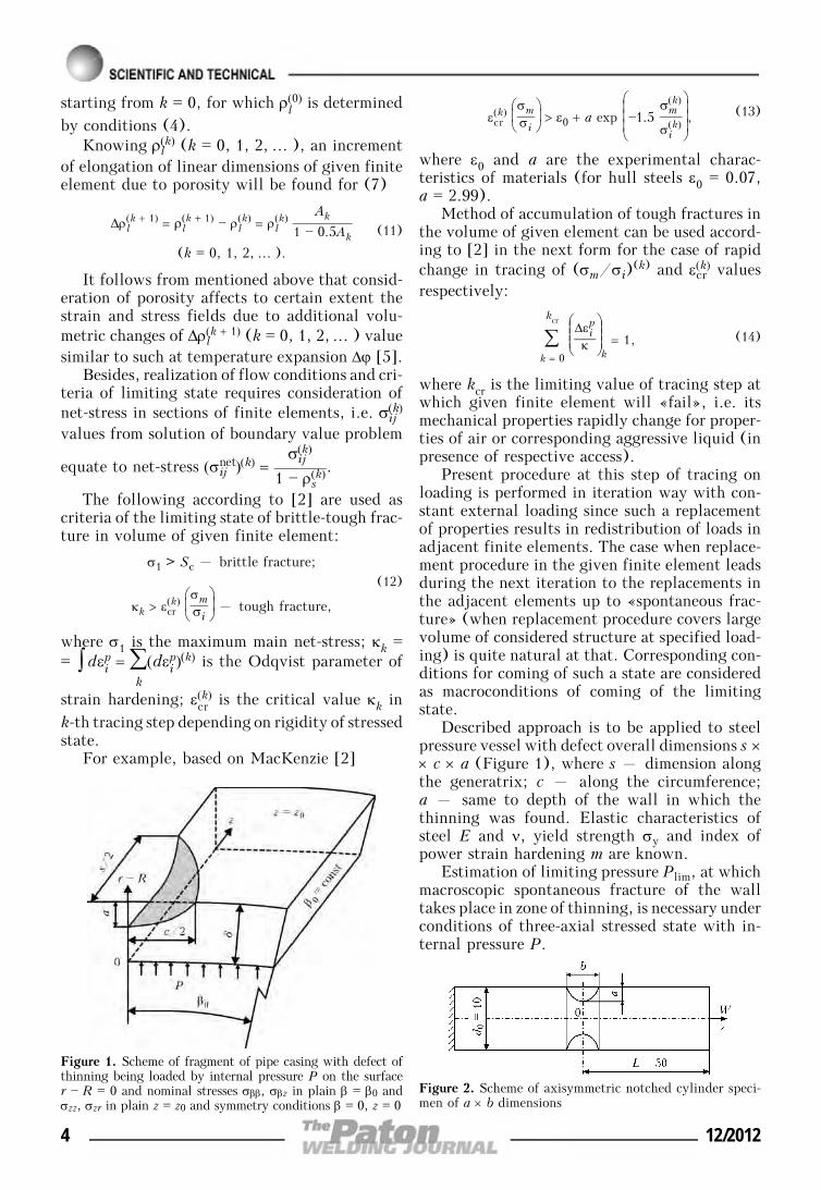
Figure 1. Scheme of fragment of pipe casing with defect ofthinning being loaded by internal pressure P on the surfacer — R = 0 and nominal stresses σββ, σβz in plain β = β0 andσzz, σzr in plain z = z0 and symmetry conditions β = 0, z = 0
Figure 2. Scheme of axisymmetric notched cylinder speci-men of a × b dimensions
4 12/2012
Algorithm of numerical determination inscope of 3D stress-strain state in zone of consid-ered defect taking no account to porosity is givenin work [6]. The latter was considered in thiswork using equations (1)—(14).
Necessary data for such a model connectedwith specified steel are proposed to be determinedusing simple tensile experiments of axisymmetricnotched cylinder specimens (Figure 2) from pipesteel with yield strength σy ≈ 480 MPa. Twodimensions of notch in 10 mm diameter specimenswere considered. The first is a × b = 1 × 3 andthe second is a × b = 3 × 1 mm at theoreticalconcentration factors αtheor = 1.60 and 3.45.
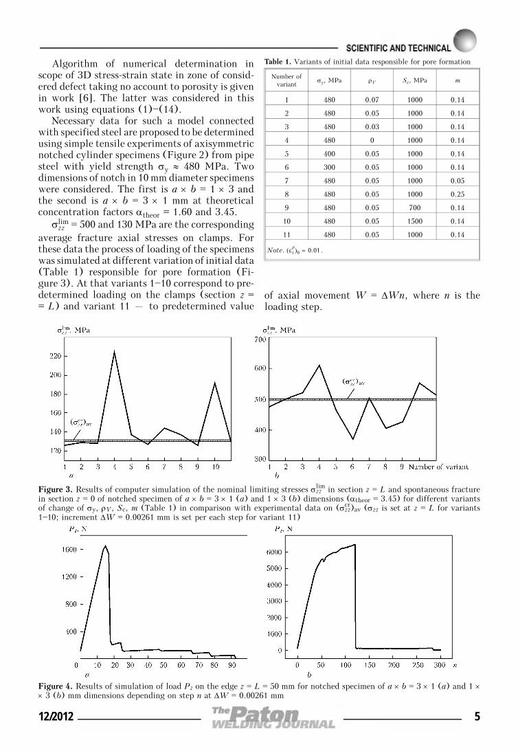
σzzlim = 500 and 130 MPa are the corresponding
average fracture axial stresses on clamps. Forthese data the process of loading of the specimenswas simulated at different variation of initial data(Table 1) responsible for pore formation (Fi-gure 3). At that variants 1—10 correspond to pre-determined loading on the clamps (section z == L) and variant 11 – to predetermined value
of axial movement W = ΔWn, where n is theloading step.
Figure 4. Results of simulation of load Pz on the edge z = L = 50 mm for notched specimen of a × b = 3 × 1 (a) and 1 ×× 3 (b) mm dimensions depending on step n at ΔW = 0.00261 mm
Table 1. Variants of initial data responsible for pore formation
Number ofvariant
σy, MPa ρV Sc, MPa m
1 480 0.07 1000 0.14
2 480 0.05 1000 0.14
3 480 0.03 1000 0.14
4 480 0 1000 0.14
5 400 0.05 1000 0.14
6 300 0.05 1000 0.14
7 480 0.05 1000 0.05
8 480 0.05 1000 0.25
9 480 0.05 700 0.14
10 480 0.05 1500 0.14
11 480 0.05 1000 0.14
Note. (εip)0 = 0.01.
Figure 3. Results of computer simulation of the nominal limiting stresses σzzlim in section z = L and spontaneous fracture
in section z = 0 of notched specimen of a × b = 3 × 1 (a) and 1 × 3 (b) dimensions (αtheor = 3.45) for different variantsof change of σy, ρV, Sc, m (Table 1) in comparison with experimental data on (σzz
cr)av (σzz is set at z = L for variants1—10; increment ΔW = 0.00261 mm is set per each step for variant 11)
12/2012 5
For this case Figure 4 shows the kinetics ofload change Pz in the process of n value growthup to coming of spontaneous fracture (withoutfurther increase of load Pz).
Correlation of σzzlim value with specified aver-
age value shows that taking no account to po-rosity (variant 4 in Figure 3) provides conserva-tive values of σzz
lim. At the same time reductionof σy below 300 MPa or Sc below 700 MPa aswell as increase of m significantly reduce σzz
lim
value. Change of porosity ρV (the main factor offracture zone embrittlement) in the range of ρV ≈≈ 0.03—0.07 provides insignificant effect onσzz
lim critical value.Fracture process taking into account pore for-
mation which promotes embrittlement of thefracture zone has sufficiently high resistance tomain parameters of the considered model (ρV,Sc, σy, m) for steel under study from this analysis.This allows using their approximate values forpractical estimations.
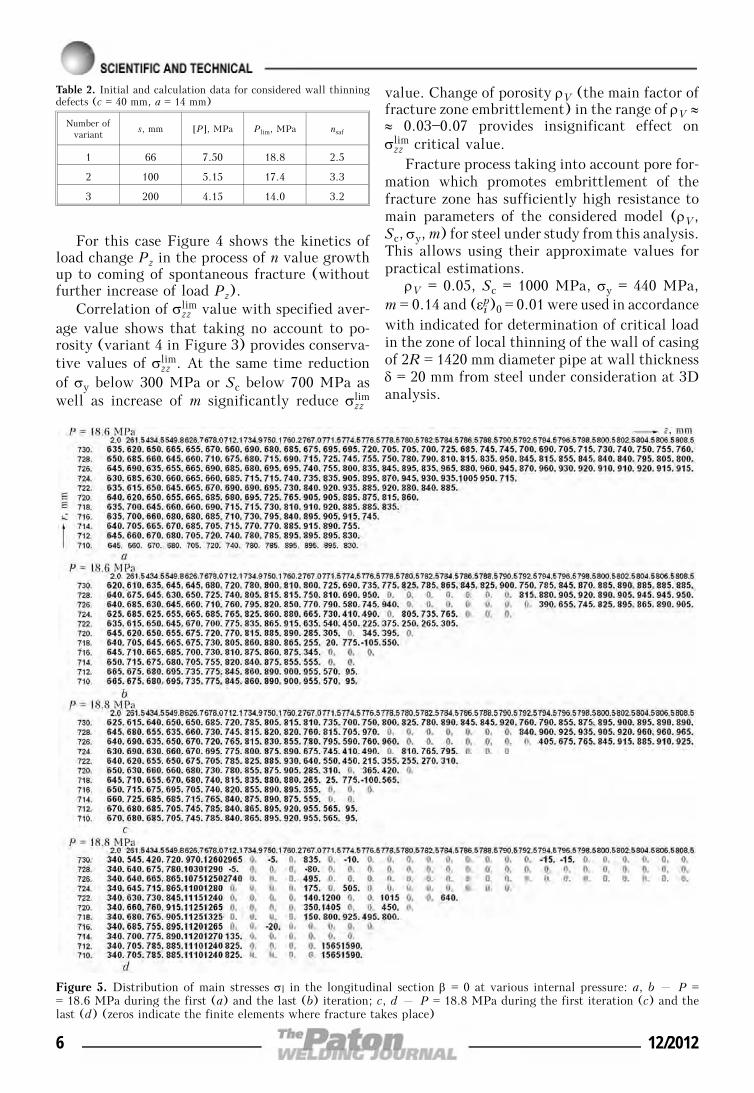
ρV = 0.05, Sc = 1000 MPa, σy = 440 MPa,m = 0.14 and (εip)0 = 0.01 were used in accordancewith indicated for determination of critical loadin the zone of local thinning of the wall of casingof 2R = 1420 mm diameter pipe at wall thicknessδ = 20 mm from steel under consideration at 3Danalysis.
Figure 5. Distribution of main stresses σl in the longitudinal section β = 0 at various internal pressure: a, b – P == 18.6 MPa during the first (a) and the last (b) iteration; c, d – P = 18.8 MPa during the first iteration (c) and thelast (d) (zeros indicate the finite elements where fracture takes place)
Table 2. Initial and calculation data for considered wall thinningdefects (c = 40 mm, a = 14 mm)
Number ofvariant
s, mm [P], MPa Plim, MPa nsaf
1 66 7.50 18.8 2.5
2 100 5.15 17.4 3.3
3 200 4.15 14.0 3.2
6 12/2012
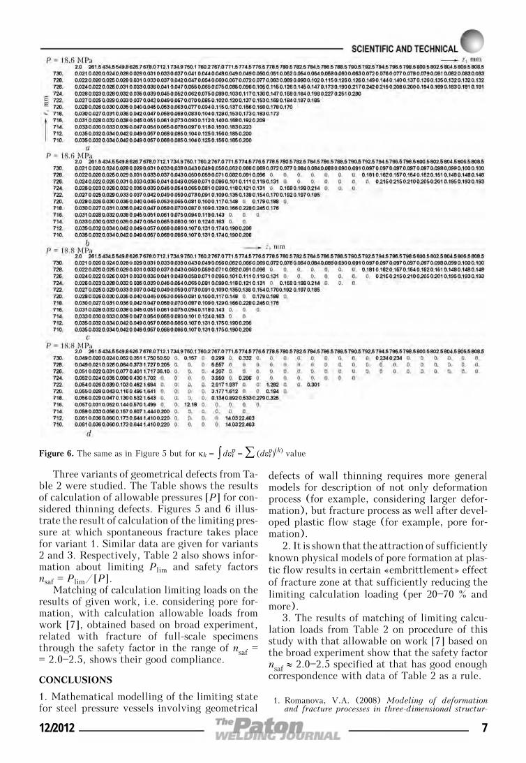
Three variants of geometrical defects from Ta-ble 2 were studied. The Table shows the resultsof calculation of allowable pressures [P] for con-sidered thinning defects. Figures 5 and 6 illus-trate the result of calculation of the limiting pres-sure at which spontaneous fracture takes placefor variant 1. Similar data are given for variants2 and 3. Respectively, Table 2 also shows infor-mation about limiting Plim and safety factorsnsaf = Plim/[P].
Matching of calculation limiting loads on theresults of given work, i.e. considering pore for-mation, with calculation allowable loads fromwork [7], obtained based on broad experiment,related with fracture of full-scale specimensthrough the safety factor in the range of nsaf == 2.0—2.5, shows their good compliance.
CONCLUSIONS
1. Mathematical modelling of the limiting statefor steel pressure vessels involving geometrical
defects of wall thinning requires more generalmodels for description of not only deformationprocess (for example, considering larger defor-mation), but fracture process as well after devel-oped plastic flow stage (for example, pore for-mation).
2. It is shown that the attraction of sufficientlyknown physical models of pore formation at plas-tic flow results in certain «embrittlement» effectof fracture zone at that sufficiently reducing thelimiting calculation loading (per 20—70 % andmore).
3. The results of matching of limiting calcu-lation loads from Table 2 on procedure of thisstudy with that allowable on work [7] based onthe broad experiment show that the safety factornsaf ≈ 2.0—2.5 specified at that has good enoughcorrespondence with data of Table 2 as a rule.
1. Romanova, V.A. (2008) Modeling of deformationand fracture processes in three-dimensional structur-
Figure 6. The same as in Figure 5 but for κk = ∫ dεip = ∑ (dεip)(k) value
12/2012 7
ally heterogeneous materials: Syn. of Thesis for Dr.of Techn. Sci. Degree. Tomsk.
2. Karzov, G.P., Margolin, B.Z., Shvetsova, V.A.(1993) Physical-mechanical modeling of fracture pro-cesses. St.-Petersburg: Politekhnika.
3. Rybin, V.V. (1986) High plastic strains and fractureof metals. Moscow: Metallurgiya.
4. (1986) Static strength and fracture mechanics ofsteels. Ed. by V. Dal, V. Antonov. Moscow: Metal-lurgizdat.
5. Makhnenko, V.I. (1976) Computational methods forinvestigation of kinetics of welding stresses andstrains. Kiev: Naukova Dumka.
6. Makhnenko, V.I., Velikoivanenko, O.A., Pozynka,G.P. et al. (2009) Stressed state in zone of thinningdefects of thin-wall pipes. In: Problems of servicelife and service safety of structures, buildings andmachines. Ed. by B.E. Paton. Kyiv: PWI.
7. (2000) Fitness-for-service: American Petroleum Insti-tute recommended practice 579. 1st ed.
INFLUENCE OF WELDING THERMAL CYCLEON STRUCTURE AND PROPERTIES
OF MICROALLOYED STRUCTURAL STEELS
V.A. KOSTIN, G.M. GRIGORENKO, V.D. POZNYAKOV, S.L. ZHDANOV, T.G. SOLOMIJCHUK,T.A. ZUBER and A.A. MAKSIMENKO
E.O. Paton Electric Welding Institute, NASU, Kiev, Ukraine
Influence of welding thermal cycle on microstructure and properties of HAZ metal in new steels withcarbide and carbonitride type of strengthening, namely 06GBD, 10G2FB, 15KSATYuD, was studied. Itis shown that under the influence of welding thermal cycle an optimum complex of ferritic-bainitic structuresforms in a rather broad range of cooling rates (w6/5 = 10—30 °C/s), which is characterized by values ofstrength, ductility and cold resistance on the level of requirements made of base metal of strength classC440.
Keywo r d s : arc welding, structural steels, carboni-tride strengthening, welding thermal cycle, Gleeble3800, microstructure, bainite, MAC-phase, mechanicalproperties
At present transportation engineering and build-ing industry of Ukraine are the main users ofhigher strength steels with yield point of up to400 MPa. Today, however, they no longer satisfy,by a number of objective factors, the require-ments of high-speed traffic or modern conceptsof urban planning, both by the level of strengthand impact toughness.
Over the recent years, PWI in cooperationwith metallurgists developed a number of newsteels with 440—590 MPa yield point, based onthe principle of carbide and carbonitridestrengthening [1, 2].
As welding is the main technological processof fabrication of structures from these steels, im-proved performance of the new steels (bystrength and impact toughness level) should bepreserved also in the welded joints. However,HAZ formation in the metal being welded leadsto deterioration of mechanical properties underthe impact of welding thermal cycle (WTC),both as a result of grain growth, and in connec-tion with formation of quenching structures.Wide introduction of new steels should be pre-
ceded by profound comprehensive investigationof these steels reaction to WTC.
Disembodied published data on the featuresof structural changes in the new steels with car-bide and carbonitride strengthening under WTCconditions are obviously insufficient [3, 4].
In addition, the clearly increased require-ments to impact toughness of new steels ofstrength class C345—440 (KCU—40 = 39 J/cm2,KCU—70 = 34 J/cm2 to GOST 27772—88) requirestudying WTC effect on strength and impacttoughness levels in HAZ metal.
The objective of this work consisted in inves-tigation of the features of formation of HAZ met-al structure under WTC impact and assessmentof microstructure influence on mechanical prop-erties and impact toughness in this zone, in orderto select optimum welding modes, ensuring highperformance of the welded joint.
Table 1 gives the composition of the studiedsteel grades. Steels 10G2FB and 06GBD belongto steels with carbide strengthening type, and15KhSATYuD steel is of carbonitride strengthen-ing type. Mechanical properties of steels in as-de-livered condition are given in Tables 2 and 3.
In order to evaluate WTC effect on the struc-ture of welded joint HAZ metal, investigationswere conducted on model samples in Geeble 3800
© V.A. KOSTIN, G.M. GRIGORENKO, V.D. POZNYAKOV, S.L. ZHDANOV, T.G. SOLOMIJCHUK, T.A. ZUBER and A.A. MAKSIMENKO, 2012
8 12/2012
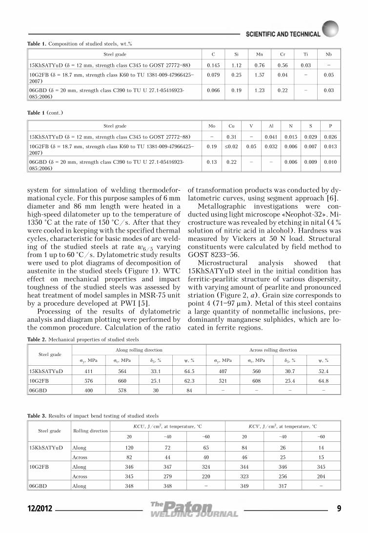
system for simulation of welding thermodefor-mational cycle. For this purpose samples of 6 mmdiameter and 86 mm length were heated in ahigh-speed dilatometer up to the temperature of1350 °C at the rate of 150 °C/s. After that theywere cooled in keeping with the specified thermalcycles, characteristic for basic modes of arc weld-ing of the studied steels at rate w6/5 varyingfrom 1 up to 60 °C/s. Dylatometric study resultswere used to plot diagrams of decomposition ofaustenite in the studied steels (Figure 1). WTCeffect on mechanical properties and impacttoughness of the studied steels was assessed byheat treatment of model samples in MSR-75 unitby a procedure developed at PWI [5].
Processing of the results of dylatometricanalysis and diagram plotting were performed bythe common procedure. Calculation of the ratio
of transformation products was conducted by dy-latometric curves, using segment approach [6].
Metallographic investigations were con-ducted using light microscope «Neophot-32». Mi-crostructure was revealed by etching in nital (4 %solution of nitric acid in alcohol). Hardness wasmeasured by Vickers at 50 N load. Structuralconstituents were calculated by field method toGOST 8233—56.
Microstructural analysis showed that15KhSATYuD steel in the initial condition hasferritic-pearlitic structure of various dispersity,with varying amount of pearlite and pronouncedstriation (Figure 2, a). Grain size corresponds topoint 4 (71—97 μm). Metal of this steel containsa large quantity of nonmetallic inclusions, pre-dominantly manganese sulphides, which are lo-cated in ferrite regions.
Table 1. Composition of studied steels, wt.%
Steel grade C Si Mn Cr Ti Nb
15KhSATYuD (δ = 12 mm, strength class C345 to GOST 27772—88) 0.145 1.12 0.76 0.56 0.03 —
10G2FB (δ = 18.7 mm, strength class K60 to TU 1381-009-47966425—2007)
0.079 0.25 1.57 0.04 — 0.05
06GBD (δ = 20 mm, strength class C390 to TU U 27.1-05416923-085:2006)
0.066 0.19 1.23 0.22 — 0.03
Table 1 (cont.)
Steel grade Mo Cu V Al N S P
15KhSATYuD (δ = 12 mm, strength class C345 to GOST 27772—88) — 0.31 — 0.041 0.015 0.029 0.026
10G2FB (δ = 18.7 mm, strength class K60 to TU 1381-009-47966425—2007)
0.19 ≤0.02 0.05 0.032 0.006 0.007 0.013
06GBD (δ = 20 mm, strength class C390 to TU U 27.1-05416923-085:2006)
0.13 0.22 — — 0.006 0.009 0.010
Table 2. Mechanical properties of studied steels
Steel gradeAlong rolling direction Across rolling direction
σy, MPa σt, MPa δ5, % ψ, % σy, MPa σt, MPa δ5, % ψ, %
15KhSATYuD 411 564 33.1 64.5 407 560 30.7 52.4
10G2FB 576 660 25.1 62.3 521 608 25.4 64.8
06GBD 400 578 30 84 — — — —
Table 3. Results of impact bend testing of studied steels
Steel grade Rolling directionKCU, J/cm2, at temperature, °C KCV, J/cm2, at temperature, °C
20 —40 —60 20 —40 —60
15KhSATYuD Along 120 72 65 84 26 14
Across 82 44 40 46 25 15
10G2FB Along 346 347 324 344 346 345
Across 345 279 220 323 256 204
06GBD Along 348 348 — 349 317 —
12/2012 9
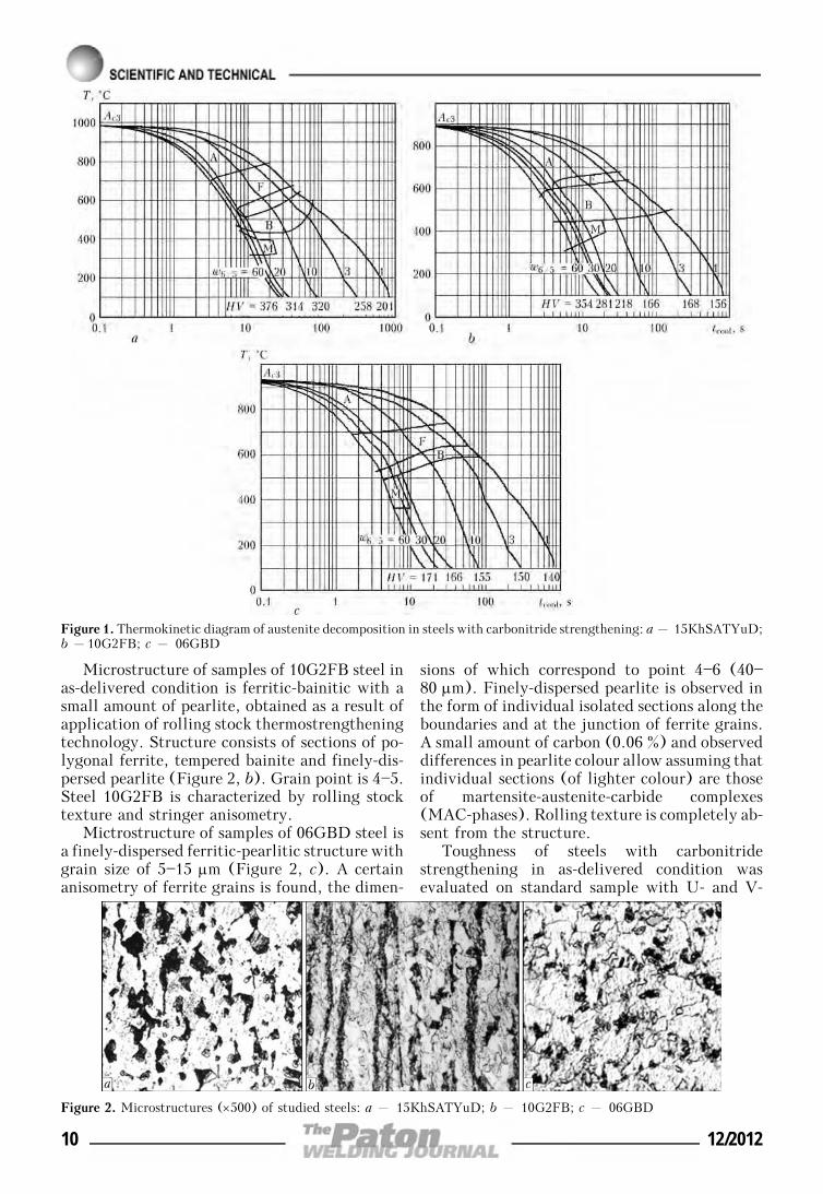
Microstructure of samples of 10G2FB steel inas-delivered condition is ferritic-bainitic with asmall amount of pearlite, obtained as a result ofapplication of rolling stock thermostrengtheningtechnology. Structure consists of sections of po-lygonal ferrite, tempered bainite and finely-dis-persed pearlite (Figure 2, b). Grain point is 4—5.Steel 10G2FB is characterized by rolling stocktexture and stringer anisometry.
Mictrostructure of samples of 06GBD steel isa finely-dispersed ferritic-pearlitic structure withgrain size of 5—15 μm (Figure 2, c). A certainanisometry of ferrite grains is found, the dimen-
sions of which correspond to point 4—6 (40—80 μm). Finely-dispersed pearlite is observed inthe form of individual isolated sections along theboundaries and at the junction of ferrite grains.A small amount of carbon (0.06 %) and observeddifferences in pearlite colour allow assuming thatindividual sections (of lighter colour) are thoseof martensite-austenite-carbide complexes(MAC-phases). Rolling texture is completely ab-sent from the structure.
Toughness of steels with carbonitridestrengthening in as-delivered condition wasevaluated on standard sample with U- and V-
Figure 1. Thermokinetic diagram of austenite decomposition in steels with carbonitride strengthening: a – 15KhSATYuD;b –10G2FB; c – 06GBD
Figure 2. Microstructures (×500) of studied steels: a – 15KhSATYuD; b – 10G2FB; c – 06GBD
10 12/2012
shaped notch for impact bending according toGOST 9454—78. Obtained results are indicativeof the fact that in 10G2FB and 06GBD steelstoughness margin is much higher than in15KhSATYuD steel, and brittle transition tem-perature is below —60 °C (Table 3).
Metallographic analysis of simulation samplesof overheating zone from 15KhSATYuD steelshowed that austenite transformation at theircontinuous cooling at the rate of 3 °C/s occurs
in the ferritic, pearlitic and bainitic regions.Therefore, this steel structure contains quite alot of ferrite (Figure 3, a). Hypoeutectoid ferriteof polygonal morphology precipitated alongaustenite grain boundaries, and sections ofpealite precipitates are observed at the junctionof ferrite grains and inside them. Widmanstattenferrite is found locally. Inside the austenite grainsof these steels the structure was identified asglobular bainite. These structural changes lead
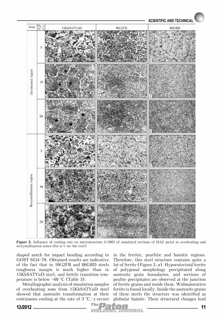
Figure 3. Influence of cooling rate on microstructure (×500) of simulated sections of HAZ metal in overheating andrecrystallization zones (for a—r see the text)
12/2012 11
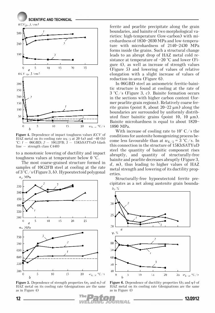
to a monotonic lowering of ductility and impacttoughness values at temperature below 0 °C.
The most coarse-grained structure formed insamples of 10G2FB steel at cooling at the rateof 3 °C/s (Figure 3, b). Hypoeutectoid polygonal
ferrite and pearlite precipitate along the grainboundaries, and bainite of two morphological va-rieties: high-temperature (low-carbon) with mi-crohardness of 1850—2030 MPa and low-tempera-ture with microhardness of 2140—2430 MPaforms inside the grains. Such a structural changeleads to an abrupt drop of HAZ metal cold re-sistance at temperature of —20 °C and lower (Fi-gure 4), as well as increase of strength values(Figure 5) and lowering of values of relativeelongation with a slight increase of values ofreduction-in-area (Figure 6).
In 06GBD steel an anisometric ferritic-baini-tic structure is found at cooling at the rate of3 °C/s (Figure 3, c). Bainite formation occursin the sections with higher carbon content (for-mer pearlite grain regions). Relatively coarse fer-rite grains (point 8, about 20—22 μm) along theboundaries are surrounded by uniformly distrib-uted finer bainitic grains (point 10, 10 μm).Bainite microhardness is equal to about 1820—1890 MPa.
With increase of cooling rate to 10° C/s theconditions for austenite homogenizing process be-come less favourable than at w6/5 = 3 °C/s. Inthis connection in the structure of 15KhSATYuDsteel the quantity of bainitic component risesabruptly, and quantity of structurally-freebainite and pearlite decreases abruptly (Figure 3,d, m), thus leading to higher values of HAZmetal strength and lowering of its ductility prop-erties.
Structurally-free hypoeutectoid ferrite pre-cipitates as a net along austenite grain bounda-
Figure 4. Dependence of impact toughness values KCV ofHAZ metal on its cooling rate w6/5 at 20 (a) and —40 (b)°C: 1 – 06GBD; 2 – 10G2FB; 3 – 15KhSATYuD (dashline – strength class C440)
Figure 5. Dependence of strength properties (σy and σt) ofHAZ metal on its cooling rate (designations are the sameas in Figure 4)
Figure 6. Dependence of ductility properties (δ5 and ψ) ofHAZ metal on its cooling rate (designations are the sameas in Figure 4)
12 12/2012
ries, whereas pearlite is sometimes found nearferrite grains. Bainite was identified as granular.Size of bainite grains at cooling rate w6/5 == 3 °C/s practically did not change.
Results of metallographic analysis of micro-structure of simulation samples from steel15KhSATYuD, formed at w6/5 = 10 °C/s, areindicative of the fact that austenite overcoolingbecomes greater at increase of cooling rate thatresults in an increase of its resistance and lower-ing of transformation temperature of both ferritefrom 800 to 750 °C, and bainite from 630 to550 °C. Amount of bainitic constituent rises. In-crease of the amount of bainite in the structurecauses an increase of hardness in the completerecrystallization region, as well as of strengthvalues. At the same time, ductility and impacttoughness values (Figure 4) decrease.
Cooling of 10G2FB steel at the rate of10 °C/s leads to narrowing of the region withoverheated structure and grain refinement. Com-pared to cooling rate of 3 °C/s, structuralchanges in this case promote a reduction of theamount of hypoeutectoid polygonal ferrite andlow-carbon bainite, and increase of the amountof high-carbon bainite (Figure 3, e, n). Pearlitictransformation at this rate is almost completelyabsent. Temperatures of ferrite and bainite trans-formation decrease to a smaller degree than in15KhSATYuD steel. Such a nature of microstruc-ture leads to a small increase of impact toughnessvalues (see Figure 4), values of strength andreduction in area are on base metal level (Fi-gures 5 and 6), whereas values of relative elon-gation decreased to 21 % (Figure 6).
Results of metallographic analysis of 06GBDsteel formed at w6/5 = 10 °C/s show that itconsists of ferrite, bainite and small regions ofMAC-phase precipitates (about 1 %, Table 4).
Bainite grains are observed in the form of elon-gated plates of upper bainite, formed both alongferrite grain boundaries, and of preservedequiaxed regions of granular bainite (Figure 3,f, o) With increase of cooling rate to w6/5 == 10 °C/s, microhardness of bainitic structurerises up to 2190 MPa, mainly due to increase ofthe quantity of its high-temperature species.MAC-phase distribution in the structure is uni-form. Change of phase transformation tempera-ture turns out to be negligible (lowering by ap-proximately 20—30 °C).
Analysis of microstructure of simulation sam-ples from 15KhSATYuD steel formed as a resultof cooling at the rate of w6/5 = 20 °C/s (Fi-gure 3, g, p) showed a complex combination ofbainite of granular and plate-like morphology,
as well as hypoeutectoid ferrite and a small quan-tity of acicular ferrite. Bainite microhardnesschanges from 2150—2200 (for granular bainite)to 1930—1980 MPa (for plate-like bainite).
Microstructure of samples from steel 10G2FBformed as a result of cooling at the rate of w6/5 == 20 °C/s revealed further narrowing of the re-gion simulating the overheating zone, at reduc-tion of grain size. In the simulated region struc-ture hypoeutectoid polygonal ferrite is seldomfound along grain boundaries. Main componentsof such metal structure are low-temperaturebainite (granular, with microhardness of 2100 to2360 MPa) and to a smaller extent – high-tem-perature bainite (1850—2030 MPa) (Figure 3, h,q). Values of strength, ductility and cold resis-tance almost did not change.
Cooling of 06GBD steel at the rate of w6/5 == 20 °C/s leads to further increase of the amountof products of intermediate transformation(bainite and MAC-phases, Table 4). Microhard-ness of bainitic component rises up to 2220—2390 MPa (Figure 3, i, r). Strength and impacttoughness values in 06GBD steel remain on thelevel of 10G2FB steel.
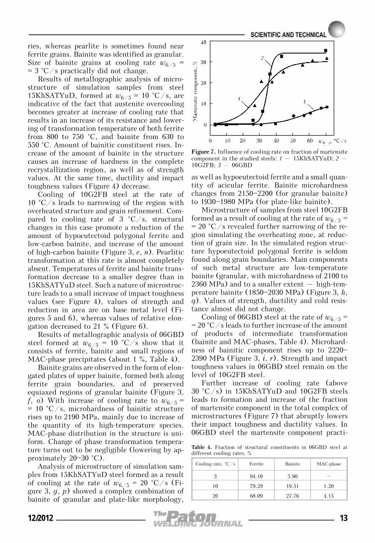
Further increase of cooling rate (above30 °C/s) in 15KhSATYuD and 10G2FB steelsleads to formation and increase of the fractionof martensite component in the total complex ofmicrostructures (Figure 7) that abruptly lowerstheir impact toughness and ductility values. In06GBD steel the martensite component practi-
Figure 7. Influence of cooling rate on fraction of martensitecomponent in the studied steels: 1 – 15KhSATYuD; 2 –10G2FB; 3 – 06GBD
Table 4. Fraction of structural constituents in 06GBD steel atdifferent cooling rates, %
Cooling rate, °C/s Ferrite Bainite MAC-phase
3 94.10 5.90 —
10 79.29 19.51 1.20
20 68.09 27.76 4.15
12/2012 13
cally does not form, because of low carbon con-tent (0.06 %) that is in good agreement withmechanical testing results.
Comparison of mechanical testing results ofsamples, simulating the HAZ of the studied steels(see Figures 4—6) shows that increase of coolingrate leads to gradual increase of yield point andstrength, as well as ductility lowering due toincrease of martensitic component. WTC has thegreatest effect on impact toughness at below zerotemperatures (see Figure 4, b). In 10G2FB steelKCV—40 impact toughness decreases from 320 to25 J/cm2, in 06GDB steel – from 170 to50 J/cm2, and in 15KhSATYuD steel – from46 to 22 J/cm2 already at the cooling rate of1 °C/s. Such an abrupt drop of toughness ofsteels with carbide strengthening can be associ-ated with partial dissolution of the carbide phasesduring WTC [7]. At further increase of coolingrate from 1 up to 30 °C/s, sample toughnessslightly rises due to a change in bainitic structuremorphology from plate-like to granular one.
At impact bend testing of standard sampleswith U-shaped notch all the studied steel dem-onstrated a good toughness (KCU—40 ≥≥ 50 J/cm2). At impact bend testing of standardsamples with a sharp V-shaped notch impact prop-erties at below zero temperatures (to —40 °C) cor-respond to the requirements of GOST 27772—88for steels of strength class C345—440 only forsteels with carbide strengthening 10G2FB and06GBD at cooling rates of 10—25 °C/s.
Impact toughness of simulation samples of15KhSATYuD steel with a sharp notch KCU—40at cooling rate of 10 °C/s is equal to 20 J/cm2,and at 25 °C/s it is only 12 J/cm2 that is relatedto the features of arrangement of carbonitrideparticles during secondary precipitation [8]. In-vestigations reveal the need for correction of thecomposition of 15KhSATYuD steel, in order toimprove its toughness at WTC impact.
Results of these investigations were a scien-tific basis for application of new 06GBD steel inconstruction of a motor road bridge across theentrance to the Bay of Podol Bridge Crossing inKiev [9] and application steel of 10G2FB typein the arch structure of the roofing of a newstadium in Kazan (Russia).
CONCLUSIONS
1. Under the conditions of WTC simulation atcooling rates of 1—60 °C/s, austenite transfor-mation in the studied steels 15KhSATYuD,10G2FB and 06GBD occurs in the ferritic, bain-itic and martensitic regions.
2. At impact bend testing of standard sam-ples with U-shaped notch all the studied steels15KhSATYuD, 10G2FB and 06GBD demon-strated high performance (according to GOSTKCU—60 > 29.4 J/cm2). At testing of standardsamples with a sharp V-shaped notch only steels10G2FB and 06GBD with carbide strengthen-ing at cooling rates up to 1 and 10—25 °C/scorrespond to the requirements (according toGOST KCU—40 > 39 J/cm2).
3. Optimum values of mechanical propertiesand impact toughness in samples of steels10G2FB and 06GBD are achieved due to forma-tion of a ferritic-bainitic structure in them atcooling rates of 10—25 °C/s with a small amountof brittle martensitic phase.
1. Matrosov, Yu.I., Litvinenko, D.A., Golovanenko,S.A. (1989) Steel for main pipelines. Moscow: Me-tallurgiya.
2. Shipitsyn, S.Ya., Babaskin, Yu.Z., Kirchu, I.F. et al.(2008) Microalloyed steel for railway wheels. Stal, 9,76—79.
3. Gretsky, Yu.Ya., Demchenko, Yu.V., Vasiliev, V.G.(1993) Formation of HAZ metal structure of low-sili-con steel with carbonitride strengthening. Avtoma-tich. Svarka, 9, 3—5, 22.
4. Zakharova, I.V., Chichkarev, E.A., Vasiliev, V.G. etal. (2001) Structure and properties of HAZ metal oflow-alloyed pipe steels modified with calcium. ThePaton Welding J., 8, 14—17.
5. Sarzhevsky, V.A., Sazonov, V.Ya. (1981) Unit for si-mulation of welding thermal cycles on the base ofMSR-75 machine. Avtomatich. Svarka, 5, 69—70.
6. Steven, W., Mayer, G. (1953) Continuous-coolingtransformation diagrams of steels. Pt 1. J. Iron andSteel Institute, 174, 33—45.
7. Livshits, L.S. (1979) Metals science for welders(welding of steels). Moscow: Mashinostroenie.
8. Zmienko, D.S., Stepanova, I.A., Yaropolova, E.I. etal. (2008) Identification of nanoparticles of niobiumcarbide in steel 10Kh13G12S2N2D2B. Zavod. Labo-ratoriya. Diagn. Mater., 74(6), 40—42.
9. Sineok, O.G., Gerasimenko, A.M., Ryabokon, V.D.et al. (2010) Application of current welding consu-mables and technologies for welding of improvedstrength rolled metal. Visnyk Dnipropetr. Nats. Un-tu Zalizn. Transporty im. Akad. V. Lazaryana, Issue33, 245—250.
14 12/2012
RESIDUAL STRESSES IN CIRCUMFERENTIAL BUTTJOINTS IN THE MAIN GAS PIPELINE
AT LONG-TERM SERVICE IN THE NORTH
N.I. GOLIKOV and V.V. DMITRIEVV.P. Larionov Institute of Physico-Technical Problems of the North, SD RAS, Yakutsk, RF
Fields of residual welding stresses in circumferential butt joints of the main pipeline of 530 mm diameterwith 7 mm wall thickness after long-term service under the North conditions were experimentally studied.It is shown that a high level of tensile residual welding stresses is preserved in circumferential weldedjoints of the main gas pipeline after 40 years of service. In sites of corrugation formation the residualwelding stresses may reach 87 % of base metal yield point. They should be taken into account at calculationof residual life of welded main pipelines.
Keywo r d s : main welded gas pipelines, circumferen-tial butt joints, HAZ, residual tensile welding stresses,corrugation, residual life
Service period of some sections of operating maingas pipelines Kysyl—Syr—Mastakh—Berge—Yakutsk, which were put into operation in 1967—1988, is up to 40 years. Acquisition and treatmentof statistical data on failures of the main gaspipeline have been performed since the momentof its putting into operation. Analysis of the mostcharacteristic causes for gas pipeline failures re-vealed that more than 50 % of failures are incircumferential welds with formation of athrough-thickness crack. Studying the causes forformation of blowholes showed that the mainsites of fracture are defects of welding the rootweld (lacks-of-penetration, pores, slags) whichare stress raisers [1].
It is known that during welding of field buttjoints of pipelines a stress-strain state formswhich is induced by a field of residual weldingstresses (RWS). One of the features of weldingcircumferential welds of cylindrical shells is de-velopment of weld «sagging», i.e. radial displace-ments leading to narrowing of pipe diameter inthe section of welded joint. This results in low-ering of hoop RWS (σθ), and at a certain com-bination of welding modes, metal properties andshell rigidity parameters σθ in the weld can evenbe close to 0. Axial stresses σz from the shellinner side turn out to be tensile because of bend-ing, and on the metal surface from the outer sidethey are compressive [2, 3]. Level of tensile RWSfrom the inner side of shell wall can reach thebase metal yield point [4]. In study [5] circum-ferential residual strains of a welded butt jointof a pipe from austenitic steel 10Kh18N10T were
measured using strain gauges (10 mm base). Pro-ceeding from the obtained data tensile residualwelding strains were found in 25—30 mm zonefrom the weld center on the pipe inner and outersurface. Thus, tensile RWS of circumferentialbutt joints of pipes are one of the factors stronglyinfluencing appearance of through-thickness brit-tle cracks in welds.
It is known that at considerable elastoplasticdeformations a practically complete relaxationof RWS takes place. In this connection, in thefield of quasi-static failures RWS do not affectthe cyclic strength of the welded joint. At loadingof the corresponding regions of low-cycle fatigue,RWS relaxation usually proceeds quite inten-sively during the first several cycles [6]. At thesame time, data of investigation of RWS relaxa-tion at long-term operation of structures are prac-tically absent. In service the fields of RWS dis-tribution in pipe welded butt joints change as aresult of an abrupt temperature gradient, struc-tural changes and elastoplastic deformation. Inthis connection RWS were studied in circumfer-ential butt joints of the main gas pipeline of530 mm diameter, 7 mm wall thickness, whichwas in operation for about 40 years.
RWS measurements in the subsurface layersof the pipe on the inner and outer sides wereconducted using a portable X-ray stress determi-nation unit.
The first coil of a pipe fragment with a cir-cumferential butt joint was cut out of a sectionof the main gas pipeline Berge—Yakutsk, becauseof formation of a corrugation in it in service.Mechanical characteristics of pipe base metalwere σt = 501 MPa, σy= 383 MPa and δ = 24.9 %.By the results of mechanical testing and spectral
© N.I. GOLIKOV and V.V. DMITRIEV, 2012
12/2012 15
analysis, pipe metal corresponds to low-alloyedsteel of 09G2S grade.
Modes of welding the main gas pipeline aregiven in the monograph of Prof. V.P. Larionov[7]. Welding was performed in three layers withapplication of Sv-10G2 welding wire (2 mm di-ameter) and AN-348A flux, baked at the tem-perature of 250—300 °C for 1.5 h, in the followingmodes: Iw = 440—500 A, Uw = 38—42 V, vw == 32—35 m/h. This ensured heat input level inthe range of 1600—1900 kJ/m that is optimumto produce a welded joint with the required heatresistance. Weld reinforcement was equal to 2—3 mm with a smooth transition to base metal,weld width was 18—20 mm.
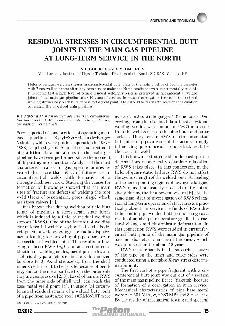
In gas pipeline service a corrugation of520 mm length and 7 mm height formed at 80 mmdistance from the welded joint. RWS measure-ments were conducted in the corrugation section,as well as in undeformed section from the pipeopposite side. By the results of measurementsfrom the pipe outer side it was established (Fi-gure 1, a) that considerable tensile stresses arefound at 30 mm distance from weld center, reach-ing 300 MPa in the circumferential direction,and up to 200 MPa in the axial direction (at40 mm distance). Near the corrugation the natureof stress variation is as follows: considerable com-pressive stresses are found in the circumferentialand axial directions, reaching 150—200 MPa. Onthe inner surface of pipe wall in the near-weldzone a high level of tensile RWS is found in theaxial direction, reaching 350 MPa. In points nearthe corrugation, compressive stresses are foundin the circumferential direction (up to 150 MPa)and negligible stresses are observed in the axialdirection.
Thus, corrugation formation results in appear-ance of considerable tensile stresses in the HAZof the weld on the inner and outer subsurfacelayers.
In the section from the opposite side on pipeouter surface (Figure 1, b) a high level of tensileand compressive stresses is found in the axial
Figure 1. Distribution of residual welding stresses of circumferential butt joint of the first coil of 530 mm diameter gaspipeline from the corrugation side (a) and undeformed section (b): 1 – axial; 2 – hoop stresses
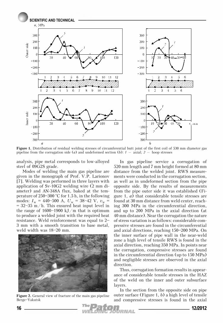
Figure 2. General view of fracture of the main gas pipelineBerge—Yakutsk
16 12/2012
direction, reaching 250 MPa at maximum. Onthe pipe inner surface RWS level at 15 mm dis-tance is equal to 230 MPa.
Second coil was cut out of the main gas pipe-line section, where the accident occurred. It con-sists of complete opening of metal along the pipe-line from the outer side with numerous branchesof the crack in the site of field circumferentialjoint (Figure 2). After the accident fracture frag-ment of the total length of 2160 mm were col-lected. Circumferential weld was broken in thetransverse direction into four individual sections:1010; 235; 315; 127 mm, respectively. Total weldlength around the perimeter is equal to 1687 mm.Fracture was of explosive nature without igni-tion. Cracks propagated by tearing mechanismin the sites of crack arresting, developing intothe shear mechanism with ductile components.
Investigation of pipe fracture surface showedthat the fracture nucleus is located on the pipeinner side, normal to the circumferential weld inthe HAZ in the site of joining of base metal andweld, and has a considerable extent and lengthof time of crack growth. Fracture surface is in-dicative of long-term propagation of the crack.
Crack stopped at transition to base metal thatis demonstrated by the transition zone. Then thecrack started moving in-depth of base material,where radial scars were observed, originatingfrom this zone and later on going into the maincrack which had a chevron pattern. Crack propa-gated for a longer time and more uniformly inthe direction normal to base metal, under theimpact of maximum tensile stresses, which arecharacterized by fatigue ridges. It stopped di-rectly in the weld that is indicative of sufficientresistance of weld metal to crack propagation,compared to base metal.
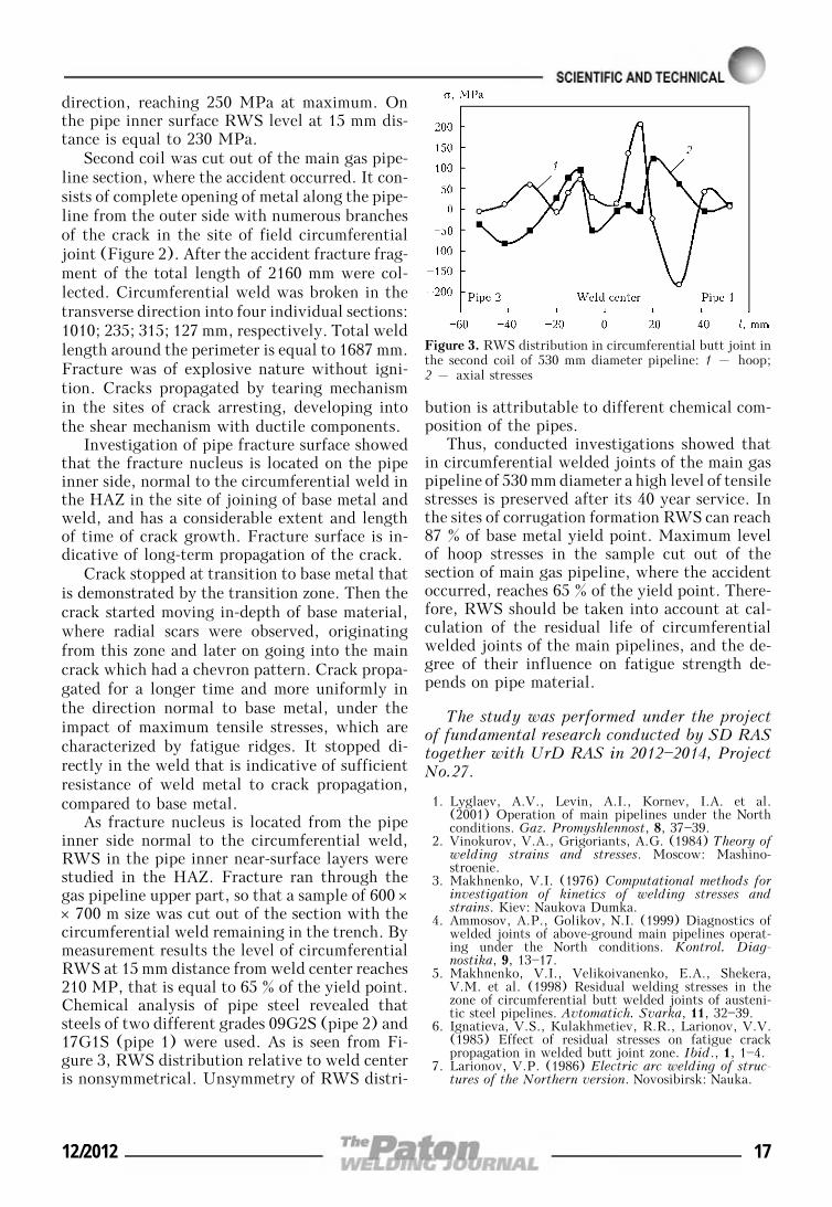
As fracture nucleus is located from the pipeinner side normal to the circumferential weld,RWS in the pipe inner near-surface layers werestudied in the HAZ. Fracture ran through thegas pipeline upper part, so that a sample of 600 ×× 700 m size was cut out of the section with thecircumferential weld remaining in the trench. Bymeasurement results the level of circumferentialRWS at 15 mm distance from weld center reaches210 MP, that is equal to 65 % of the yield point.Chemical analysis of pipe steel revealed thatsteels of two different grades 09G2S (pipe 2) and17G1S (pipe 1) were used. As is seen from Fi-gure 3, RWS distribution relative to weld centeris nonsymmetrical. Unsymmetry of RWS distri-
bution is attributable to different chemical com-position of the pipes.
Thus, conducted investigations showed thatin circumferential welded joints of the main gaspipeline of 530 mm diameter a high level of tensilestresses is preserved after its 40 year service. Inthe sites of corrugation formation RWS can reach87 % of base metal yield point. Maximum levelof hoop stresses in the sample cut out of thesection of main gas pipeline, where the accidentoccurred, reaches 65 % of the yield point. There-fore, RWS should be taken into account at cal-culation of the residual life of circumferentialwelded joints of the main pipelines, and the de-gree of their influence on fatigue strength de-pends on pipe material.
The study was performed under the projectof fundamental research conducted by SD RAStogether with UrD RAS in 2012—2014, ProjectNo.27.
1. Lyglaev, A.V., Levin, A.I., Kornev, I.A. et al.(2001) Operation of main pipelines under the Northconditions. Gaz. Promyshlennost, 8, 37—39.
2. Vinokurov, V.A., Grigoriants, A.G. (1984) Theory ofwelding strains and stresses. Moscow: Mashino-stroenie.
3. Makhnenko, V.I. (1976) Computational methods forinvestigation of kinetics of welding stresses andstrains. Kiev: Naukova Dumka.
4. Ammosov, A.P., Golikov, N.I. (1999) Diagnostics ofwelded joints of above-ground main pipelines operat-ing under the North conditions. Kontrol. Diag-nostika, 9, 13—17.
5. Makhnenko, V.I., Velikoivanenko, E.A., Shekera,V.M. et al. (1998) Residual welding stresses in thezone of circumferential butt welded joints of austeni-tic steel pipelines. Avtomatich. Svarka, 11, 32—39.
6. Ignatieva, V.S., Kulakhmetiev, R.R., Larionov, V.V.(1985) Effect of residual stresses on fatigue crackpropagation in welded butt joint zone. Ibid., 1, 1—4.
7. Larionov, V.P. (1986) Electric arc welding of struc-tures of the Northern version. Novosibirsk: Nauka.
Figure 3. RWS distribution in circumferential butt joint inthe second coil of 530 mm diameter pipeline: 1 – hoop;2 – axial stresses
12/2012 17
FORMATION OF SPINEL IN MELTOF THE MgO—Al2O3—SiO2—CaF2 SYSTEM
AGGLOMERATED WELDING FLUXAND ITS EFFECT ON VISCOSITY OF SLAG
I.A. GONCHAROV1, V.E. SOKOLSKY2, A.O. DAVIDENKO2, V.I. GALINICH1 and D.D. MISHCHENKO1
1E.O. Paton Electric Welding Institute, NASU, Kiev, Ukraine2Taras Shevchenko National University, Kiev, Ukraine
X-ray examinations of structure of agglomerated flux of the MgO—Al2O3—SiO2—CaF2 system in solid andmolten states evidence that in a temperature range above 1200 °C the Al2MgO4 hard spinel phase with amelting temperature of 2105 °C forms in the slag melt. It determines physical-chemical properties of themelt and, in particular, the smooth character of viscosity changes in a temperature range of 1180—1540 °C.By manipulating proportions and concentrations of spinel-forming components Al2O3 and MgO, it is possibleto achieve the optimal values of the temperature dependence of viscosity of the slag melt and, on this base,develop welding fluxes with predictable technological properties.
Keywo r d s : welding, agglomerated flux, structureof slag melts, viscosity, diffraction examinations, spinel
Conventional-strength steels have been gradu-ally replaced lately by increased- and high-strength steels. To weld such steels it is necessaryto use a number of appropriate metallurgicalprocesses and consumables.
Welding of conventional-strength steels isperformed by using the MnO—SiO2—CaF2 slagsystem fluxes characterised by good welding-technological properties. The latter are achieveddue to the fact that structure of the melts of thesefluxes is determined by a silicate skeleton of adiffering polymerisation degree, which, in turn,determines physical-chemical properties of slagin the molten state at temperatures of existenceof the weld pool. To provide formation of thedefect-free welds in submerged-arc welding theslag pool should damp oscillations of the metalpool. Therefore, slags must be characterised bya smooth increase in viscosity with decrease intemperature, i.e. they must be «long» [1]. How-ever, despite good technological properties, themanganese-silicate fluxes have limited possibili-ties in terms of affecting the values of mechanicalproperties of the weld metal, and impact tough-ness in particular. This is explained by the factthat welding by using these fluxes involves theprocesses of formation of silicate non-metallicinclusions and reduction of silicon in the weldmetal, which are undesirable for increased-strength steels. To achieve required mechanical
properties in welding of high-strength steels, nor-mally the use is made of high-basicity fluxes withan increased content of calcium oxide and fluo-ride. However, they fail to provide stability ofthe welding process and quality formation of thewelds in multi-arc welding of pipes at a speed ofmore than 100 m/h, as they are «short», unlikethe manganese-silicate fluxes.
Agglomerated fluxes are finding growing ap-plication in welding of high- and increased-strength steels. This is attributable to their widermetallurgical possibilities of affecting the weldpool metal. In general, the problems of sub-merged-arc welding of low-alloy high-strengthsteels by using agglomerated fluxes are consid-ered in detail in studies by I.K. Pokhodnya [2],D. Olson [3], T. Eagar [4], etc. At the sametime, there are almost no studies dedicated tothe fundamental research of structure, physical-chemical properties of the slag melts in connec-tion with technological properties of the weldingfluxes.
There are several theories describing structureof the welding slag melts. But all of them applyto the equilibrium processes of metallurgy [5—8]characterised by complete remelting of slag com-ponents and formation of the liquid slag phase.Unlike the metallurgical processes, the weldingprocesses are rapid. They feature substantial tem-perature gradients in different zones of the weldpool and, hence, are far from being equilibrium.Moreover, in melting during the welding processthe majority of the agglomerated fluxes used now
© I.A. GONCHAROV, V.E. SOKOLSKY, A.O. DAVIDENKO, V.I. GALINICH and D.D. MISHCHENKO, 2012
18 12/2012
are not a homogeneous liquid, like the fusedfluxes, but a heterogeneous mixture of differentphases, some of which are crystalline. At present,there are no slag theories describing the liquid-crystalline structure of a slag, which does notallow theoretical estimation of the effect of thecrystalline component of the slag on the processesoccurring in the weld pool.
Coarse crystallites present in the matrix of aliquid part of the slag must have a considerableeffect on viscosity and, hence, welding-techno-logical properties of the flux. Therefore, one ofthe purposes of this study was to qualitativelyreveal the effect of the crystalline inclusions onviscosity of the slag.
For a number of years we have been develop-ing agglomerated welding fluxes based on theMgO—Al2O3—SiO2—CaF2 slag system. The re-sults obtained prove the possibility of developinga new generation of welding fluxes based on theabove system. Study [9] describes investigationsof structure of a welding flux of the given systemwith a low MgO content (10 wt.%), and study[10] – investigations of the processes of meltingand solidification of fluxes of the above slag sys-tem. As established in study [11], increase in thecontent of magnesium oxide in fluxes of theMgO—Al2O3—SiO2—CaF2 system leads to de-crease in thermodynamic activity of SiO2 in theslag melt. This fact is very important in terms ofmetallurgy of welding of high-strength steels, asit makes it possible to reasonably suppress theundesirable processes of silicon reduction and for-mation of silicate non-metallic inclusions in theweld metal.
Experimental conditions and analysis of ex-perimental data. X-ray examinations of structureof molten and solid slags were carried out at thePhysical Chemistry Chair of the Taras Shevchen-ko National University by using the upgradedX-ray diffractometer for examinations of melts.Monochromatisation of MoKα-radiation was per-formed by using a pair of balanced differentialfilters Zr—Y. Earlier, the diffactometer was usedto advantage for examination of fused fluxes inglassy and solid states [12]. After upgrading, thisdiffractometer allows the diffraction examina-tions of specimens to be performed both in theliquid and solid states in a temperature range of100—1700 °C. After granulation and drying of aflux, it was ground into a powder and subjectedto X-ray analysis (CuKα-radiation, diffractome-ter DRON-3M). Also, investigations were car-ried out with a solid specimen of the slag afterholding at 1500 °C on the sides of the cruciblebottom and surface.
The E.O. Paton Electric Welding Institutestudied the temperature dependence of viscosityof the investigated flux and a number of modelfluxes of the same slag system in order to deter-mine the effect of the solid phase in a liquid slagmelt on physical-chemical properties. Viscosityof slags was measured by using the rotationalviscometer in the Tamman furnace in a purifiedargon flow.
Scanning electron microscope JSM-7700Fwith the X-ray spectral microanalyser was usedfor obtaining images of the initial and remeltedfluxes, and for local chemical analysis of microin-clusions.
The powdered specimen of the flux on a graph-ite substrate and the solidified specimen of theslag produced from it by remelting in the molyb-denum crucible at a temperature of 1500 °C inthe high-purity helium atmosphere were sub-jected to electron optical examinations. The slagspecimen was examined on the side of both bot-tom and surface of the molybdenum crucible. Toprevent the effect of charging of the specimen bythe electron beam, a 3 nm thick layer of pureplatinum was sprayed on the specimen surface.
Filming of the flux specimen was carried outat temperatures of 600, 800, 1000, 1200, 1300,1400 and 1500 °C in a high-temperature vacuumchamber in the high-purity helium atmosphere.
Chemical composition of the specimens wascontrolled by the X-ray fluorescent analysismethod.
Structural software Powdercell and Mercury,data bases Match and Retrieve, which are dis-seminated free of charge through the Internet,were used to interpret the X-ray analysis data.The software developed in-house was used in cal-culations for investigation of the slag melt [12].
Investigations at room temperature. The cal-culated contents of the main components of theflux, i.e. MgO, Al2O3, SiO2 and CaF2, are givenin Table 1. Liquid glass Na—K was added to therefined mechanical mixture in the granulator. Af-ter granulation, the flux was held for 24 h at atemperature of 20 °C, and then was baked for1 h at 500 °C. The actual chemical compositionof the flux, according to the X-ray fluorescentanalysis data, is also given in Table 1.
Results of electron microscopic examinationsof the powdered agglomerated flux indicate that
Table 1. Composition of welding flux, wt.%
Type of analysis MgO Al2O3 SiO2 CaF2 Na2O K2O Fe2O3
Calculated 30 25 20 25 — — —
Actual 25.8 18.7 28.4 22.2 1.58 0.8 1.88
12/2012 19
particles of initial components MgO, Al2O3, SiO2and CaF2 hardly undergo any changes as a resultof granulation and subsequent baking at a tem-perature of 500 °C.
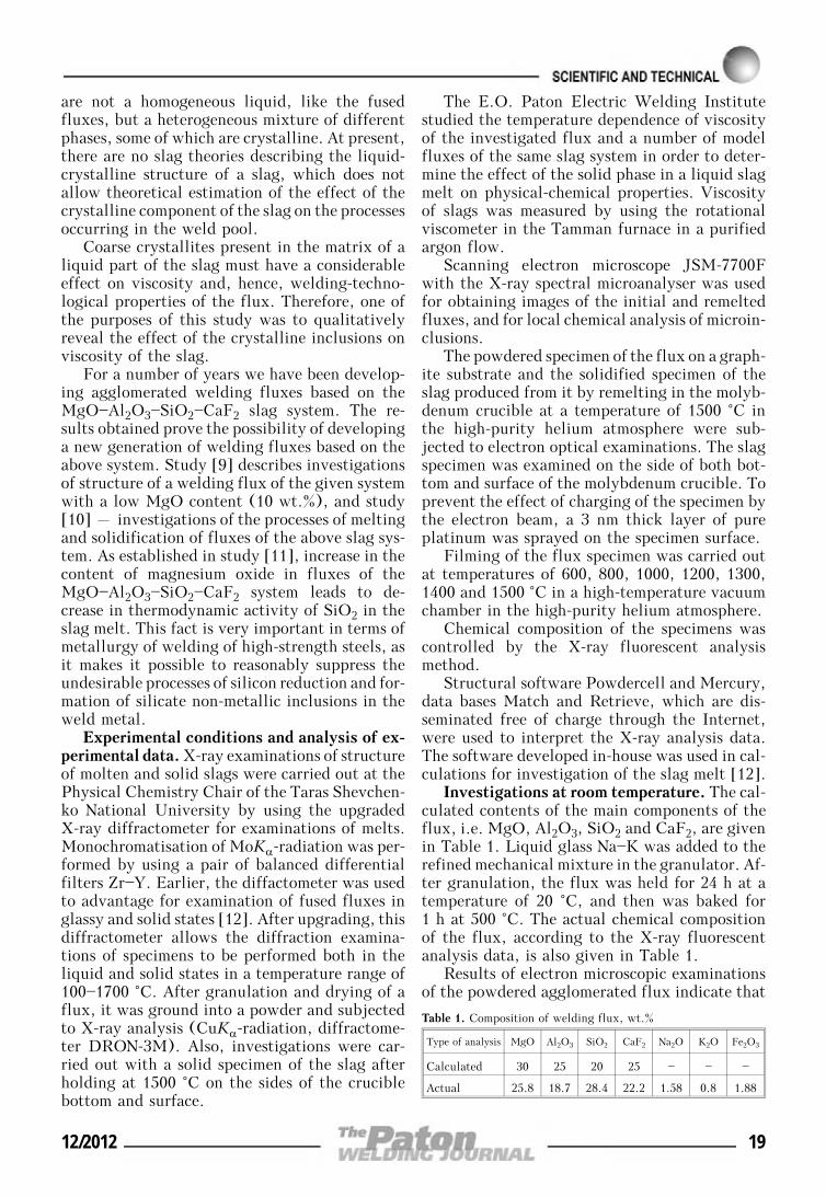
X-ray phase analysis (Figure 1) showed thatafter granulation and drying the specimen con-tained only the initial components, such as α-quartz, trigonal Al2O3, and cubic MgO and CaF2.No primary products of solidification of the com-ponents based on the liquid glass were detected.
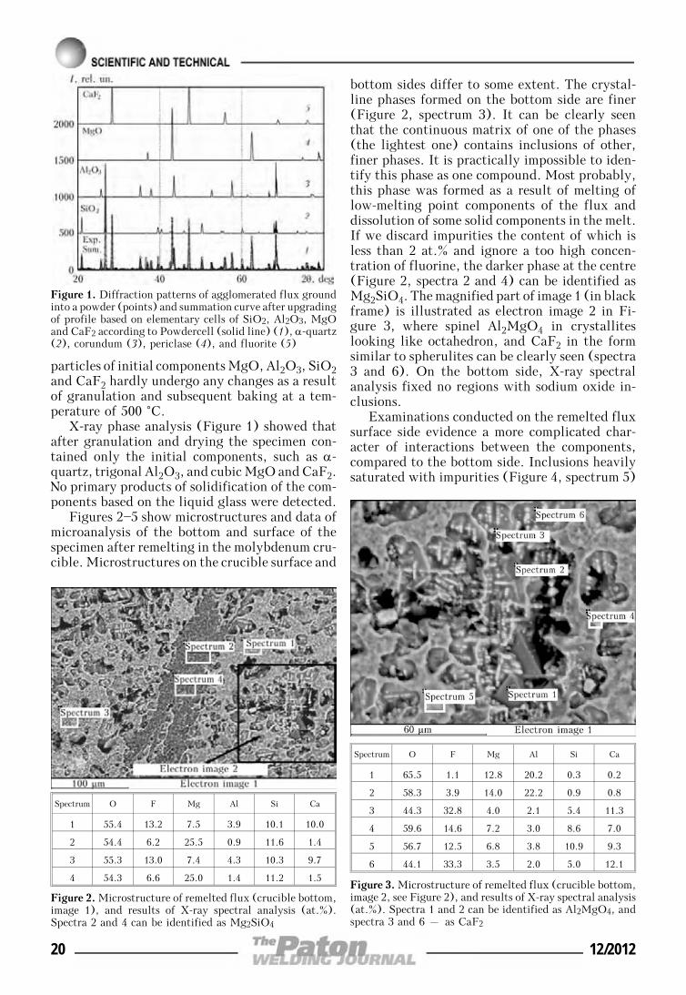
Figures 2—5 show microstructures and data ofmicroanalysis of the bottom and surface of thespecimen after remelting in the molybdenum cru-cible. Microstructures on the crucible surface and
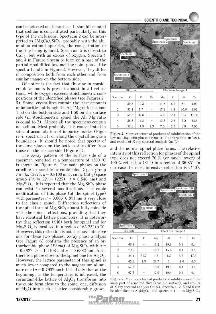
bottom sides differ to some extent. The crystal-line phases formed on the bottom side are finer(Figure 2, spectrum 3). It can be clearly seenthat the continuous matrix of one of the phases(the lightest one) contains inclusions of other,finer phases. It is practically impossible to iden-tify this phase as one compound. Most probably,this phase was formed as a result of melting oflow-melting point components of the flux anddissolution of some solid components in the melt.If we discard impurities the content of which isless than 2 at.% and ignore a too high concen-tration of fluorine, the darker phase at the centre(Figure 2, spectra 2 and 4) can be identified asMg2SiO4. The magnified part of image 1 (in blackframe) is illustrated as electron image 2 in Fi-gure 3, where spinel Al2MgO4 in crystalliteslooking like octahedron, and CaF2 in the formsimilar to spherulites can be clearly seen (spectra3 and 6). On the bottom side, X-ray spectralanalysis fixed no regions with sodium oxide in-clusions.
Examinations conducted on the remelted fluxsurface side evidence a more complicated char-acter of interactions between the components,compared to the bottom side. Inclusions heavilysaturated with impurities (Figure 4, spectrum 5)
Figure 1. Diffraction patterns of agglomerated flux groundinto a powder (points) and summation curve after upgradingof profile based on elementary cells of SiO2, Al2O3, MgOand CaF2 according to Powdercell (solid line) (1), α-quartz(2), corundum (3), periclase (4), and fluorite (5)
Spectrum O F Mg Al Si Ca
1 55.4 13.2 7.5 3.9 10.1 10.0
2 54.4 6.2 25.5 0.9 11.6 1.4
3 55.3 13.0 7.4 4.3 10.3 9.7
4 54.3 6.6 25.0 1.4 11.2 1.5
Figure 2. Microstructure of remelted flux (crucible bottom,image 1), and results of X-ray spectral analysis (at.%).Spectra 2 and 4 can be identified as Mg2SiO4
Spectrum O F Mg Al Si Ca
1 65.5 1.1 12.8 20.2 0.3 0.2
2 58.3 3.9 14.0 22.2 0.9 0.8
3 44.3 32.8 4.0 2.1 5.4 11.3
4 59.6 14.6 7.2 3.0 8.6 7.0
5 56.7 12.5 6.8 3.8 10.9 9.3
6 44.1 33.3 3.5 2.0 5.0 12.1
Figure 3. Microstructure of remelted flux (crucible bottom,image 2, see Figure 2), and results of X-ray spectral analysis(at.%). Spectra 1 and 2 can be identified as Al2MgO4, andspectra 3 and 6 – as CaF2
20 12/2012
can be detected on the surface. It should be notedthat sodium is concentrated particularly on thistype of the inclusions. Spectrum 2 can be inter-preted as (MgCa)2SiO4, probably with the alu-minium cation impurities, the concentration offluorine being ignored. Spectrum 3 is closest toCaF2, but with an excess of oxygen. Spectra 1and 4 in Figure 4 seem to form on a base of thepartially solidified low-melting point phase, likespectra 1 and 3 in Figure 2. However, they differin composition both from each other and fromsimilar images on the bottom side.
Of notice is the fact that fluorine in consid-erable amounts is present almost in all reflec-tions, while oxygen exceeds stoichiometric com-positions of the identified phases (see Figures 2—5). Spinel crystallites contain the least amountsof impurities, although the Al/Mg ratio is about1.58 on the bottom side and 1.50 on the surfaceside (in stoichiometric spinel the Al/Mg ratiois equal to 2). Almost all the specimens containno sodium. Most probably, it is concentrated insites of accumulation of impurity oxides (Figu-re 4, spectrum 5), or along the crystalline grainboundaries. It should be noted that spectra ofthe close phases on the bottom side differ fromthose on the surface side (Figure 5).
The X-ray pattern of the surface side of aspecimen remelted at a temperature of 1500 °Cis shown in Figure 6. The main phases on thecrucible surface side are cubic spinel (space groupFd—3m (227), a = 0.8100 nm), cubic CaF2 (spacegroup F4/m—32/m (225), a = 0.546 nm) andMg2SiO4. It is reported that the Mg2SiO4 phasecan exist in several modifications. The cubicmodification of this phase (of the spinel type)with parameter a = 0.806—0.811 nm is very closeto the classic spinel. Diffraction reflections ofthe spinel form of Mg2SiO4 almost fully coincidewith the spinel reflections, providing that theyhave identical lattice parameters. It is notewor-thy that reflection (440) both for spinel and forMg2SiO4 is localised in a region of 65.25° to 2θ.However, this reflection is not the most intensiveone for these two phases. X-ray phase analysis(see Figure 6) confirms the presence of an or-thorhombic phase (Pbnm) of Mg2SiO4 with a == 0.4822, b = 1.1108 and c = 0.6382 nm. Also,there is a phase close to the spinel one for Al2O3.However, the lattice parameter of this spinel ismuch lower compared to the magnesium alumi-nate one (a = 0.7932 nm). It is likely that at thebeginning, as the temperature is increased, thecorundum-like lattice of Al2O3 transforms intothe cubic form close to the spinel one, diffusionof MgO into such a lattice considerably grows,
and the normal spinel phase forms. The relativeintensity of this reflection for phases of the spineltype does not exceed 70 % (or much lower) of100 % reflection (311) in a region of 36.85°. Inour case the most intensive reflection is (440).
Spectrum O F Na Mg Al Si Ca
1 59.5 10.3 — 11.8 6.2 8.1 4.09
2 55.1 7.7 — 17.2 4.4 10.6 4.92
3 44.3 32.8 — 4.0 2.1 5.4 11.30
4 56.5 14.8 — 15.5 2.6 7.2 3.36
5 58.6 17.9 1.3 7.0 2.5 3.8 7.90
Figure 4. Microstructure of products of solidification of thelow-melting point phase of remelted flux (crucible surface),and results of X-ray spectral analysis (at.%)
Spectrum O F Mg Al Si Ca
1 66.8 — 13.2 19.8 0.1 0.1
2 73.5 — 10.7 15.6 0.1 0.1
3 24.1 51.7 1.5 1.5 3.7 17.5
4 65.6 1.3 21.7 0 11.0 0.3
5 67.3 — 13.0 19.5 0.1 0.1
6 67.5 — 12.9 19.4 0.1 0.1
Figure 5. Microstructure of products of solidification of themain part of remelted flux (crucible surface), and resultsof X-ray spectral analysis (at.%). Spectra 1, 2, 5 and 6 canbe identified as Al2MgO4, and spectrum 4 – as Mg2SiO4
12/2012 21
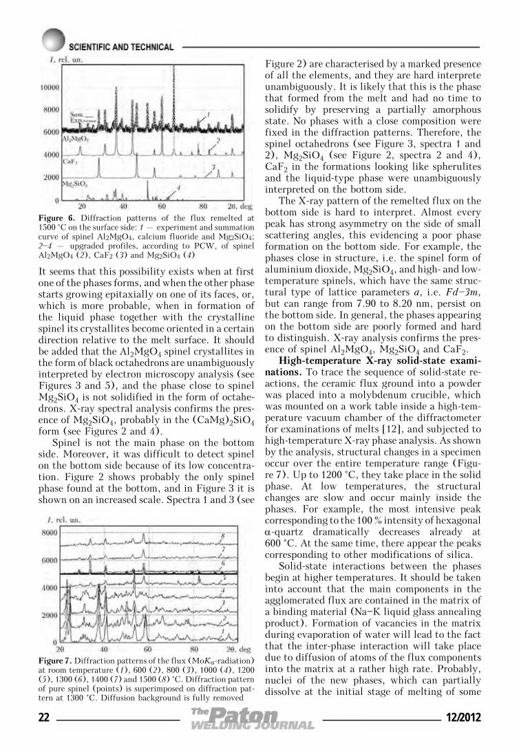
It seems that this possibility exists when at firstone of the phases forms, and when the other phasestarts growing epitaxially on one of its faces, or,which is more probable, when in formation ofthe liquid phase together with the crystallinespinel its crystallites become oriented in a certaindirection relative to the melt surface. It shouldbe added that the Al2MgO4 spinel crystallites inthe form of black octahedrons are unambiguouslyinterpreted by electron microscopy analysis (seeFigures 3 and 5), and the phase close to spinelMg2SiO4 is not solidified in the form of octahe-drons. X-ray spectral analysis confirms the pres-ence of Mg2SiO4, probably in the (CaMg)2SiO4form (see Figures 2 and 4).
Spinel is not the main phase on the bottomside. Moreover, it was difficult to detect spinelon the bottom side because of its low concentra-tion. Figure 2 shows probably the only spinelphase found at the bottom, and in Figure 3 it isshown on an increased scale. Spectra 1 and 3 (see
Figure 2) are characterised by a marked presenceof all the elements, and they are hard interpreteunambiguously. It is likely that this is the phasethat formed from the melt and had no time tosolidify by preserving a partially amorphousstate. No phases with a close composition werefixed in the diffraction patterns. Therefore, thespinel octahedrons (see Figure 3, spectra 1 and2), Mg2SiO4 (see Figure 2, spectra 2 and 4),CaF2 in the formations looking like spherulitesand the liquid-type phase were unambiguouslyinterpreted on the bottom side.
The X-ray pattern of the remelted flux on thebottom side is hard to interpret. Almost everypeak has strong asymmetry on the side of smallscattering angles, this evidencing a poor phaseformation on the bottom side. For example, thephases close in structure, i.e. the spinel form ofaluminium dioxide, Mg2SiO4, and high- and low-temperature spinels, which have the same struc-tural type of lattice parameters a, i.e. Fd—3m,but can range from 7.90 to 8.20 nm, persist onthe bottom side. In general, the phases appearingon the bottom side are poorly formed and hardto distinguish. X-ray analysis confirms the pres-ence of spinel Al2MgO4, Mg2SiO4 and CaF2.
High-temperature X-ray solid-state exami-nations. To trace the sequence of solid-state re-actions, the ceramic flux ground into a powderwas placed into a molybdenum crucible, whichwas mounted on a work table inside a high-tem-perature vacuum chamber of the diffractometerfor examinations of melts [12], and subjected tohigh-temperature X-ray phase analysis. As shownby the analysis, structural changes in a specimenoccur over the entire temperature range (Figu-re 7). Up to 1200 °C, they take place in the solidphase. At low temperatures, the structuralchanges are slow and occur mainly inside thephases. For example, the most intensive peakcorresponding to the 100 % intensity of hexagonalα-quartz dramatically decreases already at600 °C. At the same time, there appear the peakscorresponding to other modifications of silica.
Solid-state interactions between the phasesbegin at higher temperatures. It should be takeninto account that the main components in theagglomerated flux are contained in the matrix ofa binding material (Na—K liquid glass annealingproduct). Formation of vacancies in the matrixduring evaporation of water will lead to the factthat the inter-phase interaction will take placedue to diffusion of atoms of the flux componentsinto the matrix at a rather high rate. Probably,nuclei of the new phases, which can partiallydissolve at the initial stage of melting of some
Figure 6. Diffraction patterns of the flux remelted at1500 °C on the surface side: 1 – experiment and summationcurve of spinel Al2MgO4, calcium fluoride and Mg2SiO4;2—4 – upgraded profiles, according to PCW, of spinelAl2MgO4 (2), CaF2 (3) and Mg2SiO4 (4)
Figure 7. Diffraction patterns of the flux (MoKα-radiation)at room temperature (1), 600 (2), 800 (3), 1000 (4), 1200(5), 1300 (6), 1400 (7) and 1500 (8) °C. Diffraction patternof pure spinel (points) is superimposed on diffraction pat-tern at 1300 °C. Diffusion background is fully removed
22 12/2012
flux components in the molten phase, or, on thecontrary, can accumulate due to intensified in-teraction with the molten phase, will start form-ing in the matrix on a base of the liquid glassremainders. Below 1200 °C, the melts preservethe main components, although, as can be seenfrom Figure 7, intensive decrease in their peaksand, hence, destruction of the initial structurestake place. At 1200 °C, the diffraction patternsshow practically no reflections corresponding tothe initial flux components. The flux melts. How-ever, a new crystalline phase, i.e. spinelAl2MgO4, forms against the background of themolten component.
The diffraction pattern of pure spinel is su-perimposed on the diffraction pattern of a speci-men at a temperature of 1300 °C (see Figure 7).Then the spinel reflections in a temperature rangeof 1200—1500 °C coincide in location with thespecimen reflections. The relative intensity of thereflections is in some disagreement with the tabu-lar data. This can be the case if the crystallitesof spinel in the melt are oriented with a certainplane relative to the melt surface, rather thanbeing chaotically located. As the melt surface issaturated with spinel to a much greater degree,and the bottom – to a lesser degree, it can beassumed that the spinel is lighter than the liquidphase and, as such, it floats to the surface.
Discussion of results. The insignificant ad-ditions the content of which is not in excess of1 wt.% being ignored, to interpret the resultsobtained it is necessary to use a complex consti-tutional diagram of Na2O—Al2O3—MgO—SiO2—CaF2. But this oxide-fluoride diagram is notavailable in the scientific literature. The closest,well-studied constitutional diagram for the four-component system is CaO—MgO—Al2O3—SiO2[13]. As discovered in investigation of the ag-glomerated flux of the calculated MgO(10 wt.%)—Al2O3 (25 wt.%)—SiO2 (40 wt.%)—CaF2 (25 wt.%) composition, CaF2 at least par-tially transforms into an oxide [9, 14]. It wasestablished for this flux that the main phase hasthe form of anorthite, i.e. CaAl2Si2O8, wherecalcium has the oxide form. Probably, MgF2forms in small amounts. Spinel Al2MgO4 doesnot form in this case. The spinel fields appear inthe CaO—MgO—Al2O3—SiO2 diagram already ina section of 15 wt.% Al2O3. In the MgO—Al2O3binary constitutional diagram the spinel is almoststoichiometric at low temperatures, and featuresa wide range of homogeneity at high tempera-tures. Earlier the spinel was not distinguishedfrom the cubic modification of Al2O3. Solid so-lutions based on spinel MgO and Al2O3 are found
in the entire concentration range of the consti-tutional diagram at a temperature of up to2000 °C. Investigations of the solid solutions ofAl2O3 in the spinel show that they have cationvacancies, which are readily filled up from ex-ternal sources. Reaction of formation of the spinelin the solid phase from aluminium oxide beginsapproximately at 750 °C [15]. According to [13],the initial stage of formation of the spinel occursby the surface diffusion of alumina into MgO,which is followed by the volume diffusion ofatoms (ions) of magnesium and aluminiumthrough the oxygen sub-lattice to transform thehexagonal arrangement of this sub-lattice in co-rundum into the cubic one (probably, the corun-dum itself first forms the cubic lattice of thespinel type). A high melting temperature ofspinel and physical-chemical properties of theslag melts it determines arouse considerable in-terest in the spinel when developing a new gen-eration of welding fluxes. The spinel phase per-sists after remelting of the flux during the weld-ing process and its transformation into a slagcrust.
Therefore, the presence of spinel is an experi-mental fact, and it is necessary to reveal all ad-vantages and drawbacks of the presence of a solidspinel phase in the melt, as well as its effect onthe welding process. It is possible to distinguishfour moments which can be affected by formationof the crystalline spinel, although, in general,there may be much more of such moments.
1. If the thermal expansion coefficients ofspinel and liquid phase solidification productsdiffer greatly at the temperatures of detachmentof the slag crust from the weld metal (250—500 °C), this will induce microstresses in the ma-trix of the former liquid phase, thus creatingpreconditions for good detachability of the slagcrust from the surface of the metal welded.
2. The presence of the crystalline phase in theliquid slag melt at a temperature of about 1100—2000 °C will have a considerable effect on vis-cosity of the melt. Increase in the content of thecrystalline spinel in the molten slag may lead toincrease in viscosity and make the molten slag«longer», this being a positive factor in terms ofthe technological properties of the flux, whichwas already noted at the beginning of the article.
3. The general decrease in the content of elec-tricity carriers in the slag during formation ofthe spinel phase due to decrease in the quantityand mobility of elementary particles (ions andelectrons) may lead to a substantial decrease inelectrical conductivity. This also is a positivefactor, as it will allow mitigating the effect of
12/2012 23
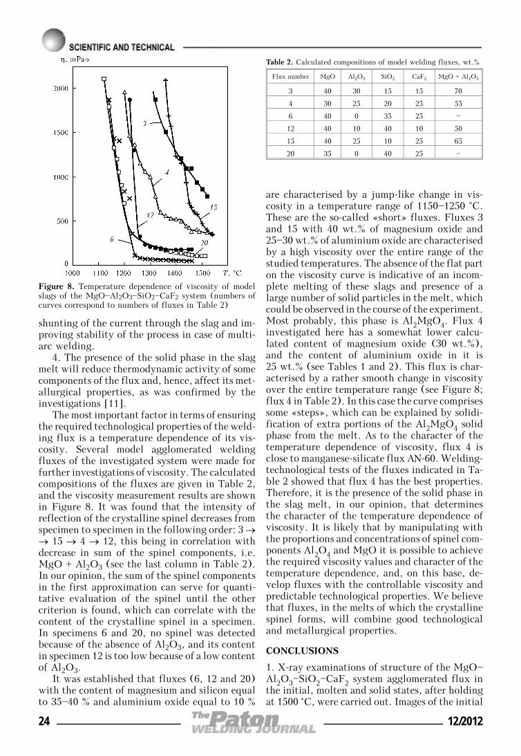
shunting of the current through the slag and im-proving stability of the process in case of multi-arc welding.
4. The presence of the solid phase in the slagmelt will reduce thermodynamic activity of somecomponents of the flux and, hence, affect its met-allurgical properties, as was confirmed by theinvestigations [11].
The most important factor in terms of ensuringthe required technological properties of the weld-ing flux is a temperature dependence of its vis-cosity. Several model agglomerated weldingfluxes of the investigated system were made forfurther investigations of viscosity. The calculatedcompositions of the fluxes are given in Table 2,and the viscosity measurement results are shownin Figure 8. It was found that the intensity ofreflection of the crystalline spinel decreases fromspecimen to specimen in the following order: 3 →→ 15 → 4 → 12, this being in correlation withdecrease in sum of the spinel components, i.e.MgO + Al2O3 (see the last column in Table 2).In our opinion, the sum of the spinel componentsin the first approximation can serve for quanti-tative evaluation of the spinel until the othercriterion is found, which can correlate with thecontent of the crystalline spinel in a specimen.In specimens 6 and 20, no spinel was detectedbecause of the absence of Al2O3, and its contentin specimen 12 is too low because of a low contentof Al2O3.
It was established that fluxes (6, 12 and 20)with the content of magnesium and silicon equalto 35—40 % and aluminium oxide equal to 10 %
are characterised by a jump-like change in vis-cosity in a temperature range of 1150—1250 °C.These are the so-called «short» fluxes. Fluxes 3and 15 with 40 wt.% of magnesium oxide and25—30 wt.% of aluminium oxide are characterisedby a high viscosity over the entire range of thestudied temperatures. The absence of the flat parton the viscosity curve is indicative of an incom-plete melting of these slags and presence of alarge number of solid particles in the melt, whichcould be observed in the course of the experiment.Most probably, this phase is Al2MgO4. Flux 4investigated here has a somewhat lower calcu-lated content of magnesium oxide (30 wt.%),and the content of aluminium oxide in it is25 wt.% (see Tables 1 and 2). This flux is char-acterised by a rather smooth change in viscosityover the entire temperature range (see Figure 8;flux 4 in Table 2). In this case the curve comprisessome «steps», which can be explained by solidi-fication of extra portions of the Al2MgO4 solidphase from the melt. As to the character of thetemperature dependence of viscosity, flux 4 isclose to manganese-silicate flux AN-60. Welding-technological tests of the fluxes indicated in Ta-ble 2 showed that flux 4 has the best properties.Therefore, it is the presence of the solid phase inthe slag melt, in our opinion, that determinesthe character of the temperature dependence ofviscosity. It is likely that by manipulating withthe proportions and concentrations of spinel com-ponents Al2O4 and MgO it is possible to achievethe required viscosity values and character of thetemperature dependence, and, on this base, de-velop fluxes with the controllable viscosity andpredictable technological properties. We believethat fluxes, in the melts of which the crystallinespinel forms, will combine good technologicaland metallurgical properties.
CONCLUSIONS
1. X-ray examinations of structure of the MgO—Al2O3—SiO2—CaF2 system agglomerated flux inthe initial, molten and solid states, after holdingat 1500 °C, were carried out. Images of the initial
Figure 8. Temperature dependence of viscosity of modelslags of the MgO—Al2O3—SiO2—CaF2 system (numbers ofcurves correspond to numbers of fluxes in Table 2)
Table 2. Calculated compositions of model welding fluxes, wt.%
Flux number MgO Al2O3 SiO2 CaF2 MgO + Al2O3
3 40 30 15 15 70
4 30 25 20 25 55
6 40 0 35 25 —
12 40 10 40 10 50
15 40 25 10 25 65
20 35 0 40 25 —
24 12/2012
and remelted flux were obtained by using scan-ning electron microscope JSM-7700F fitted withthe X-ray spectral microanalyser, and localchemical compositions of the microinclusionswere determined. Viscosity of the slags was meas-ured by using the rotational viscometer in a pu-rified argon flow inside the Tamman furnace.
2. The examinations conducted evidence acomplex character of interactions taking place inthe agglomerated flux before formation of themolten slag phase. The main structural changesin heating the flux to 1200 °C occur due to thesolid-phase interactions in a product formed bya cake of the liquid glass with the adjacent maincomponents of the flux.
3. Formation of the liquid phase begins in atemperature range of about 1200 °C due to melt-ing of the cake of the liquid glass with the maincomponents and complex unstable compounds.The solid Al2MgO4 spinel phase having a meltingtemperature of 2105 °C forms in this case in themelt. Full melting of the flux of the investigatedcomposition does not take place in a temperaturerange of up to 1500 °C. This phase persists in theslag crust after remelting of the flux during thewelding process. The presence of the solidAl2MgO4 phase in the slag melt of the MgO—Al2O3—SiO2—CaF2 system determines its physi-cal-chemical properties, in particular the smoothcharacter of viscosity changes in a temperaturerange of 1180—1540 °C.
4. It is an established fact that by manipulat-ing the proportions and concentrations of spinel-forming components Al2O3 and MgO it is possi-ble to achieve the optimal values of the tempera-ture dependence of viscosity of the slag melt and,on this base, develop welding fluxes with con-trollable technological properties.
The authors express their gratitude to Com-pany «Tokyo Boeki» and personally to Dr. Tin-kov V.A. for conducting electron microscopy ex-
aminations and assistance in interpretation ofthe obtained results.
1. Podgaetsky, V.V., Lyuborets, I.I. (1984) Weldingfluxes. Kiev: Tekhnika.
2. Pokhodnya, I.K., Yavdoshchin, I.R., Shvachko, V.I.et al. (2004) Metallurgy of arc welding. Interactionof gases with metals. Ed. by I.K. Pokhodnya. Kiev:Naukova Dumka.
3. Olson, D.L. (1983) The investigation of the influ-ence of welding flux on the pyrometallurgical, physi-cal and mechanical behavior of weld metal. In: Finalreport of Center for welding research Coloradoschool of mines Golden Colorado.
4. Eagar, T.W. (1991) Thermochemistry of joining. In:Proc. of Elliot Symp. on Chemical Process Metal-lurgy.
5. Herasymenko, P., Speigth, G.E. (1950) Ionic theoryof slag-metal equilibrium. J. Iron and Steel Inst.,166, 169—183, 289—303.
6. Tyomkin, M.I. (1946) Mixtures of molten salts asionic solutions. Zhurnal Fizich. Khimii, Issue 1,105—110.
7. Kozheurov, V.A. (1955) Thermodynamics of metal-lurgical slags. Sverdlovsk: Metallurgizdat.
8. Esin, O.A. (1961) About the nature of molten sili-cates. Tr. Ural. Polytechn. In-ta, Issue 122, 29—39.
9. Sokolskii, V.E., Roik, A.S., Davidenko, A.O. et al.(2012) X-ray diffraction and sem/edx studies ontechnological evolution of the oxide-fluoride ceramicflux for submerged arc-surfacing. J. Min. Metall. B,48, 101—113.
10. Duchenko, A.N., Mishchenko, D.D., Goncharov, I.A.et al. (2011) Study of the process of melting and soli-dification of fluxes of the Al2O3—MgO—SiO2—CaF2slag system. In: Proc. of 13th Rus. Conf. on Structu-re and Properties of Metallic and Slag Melts.Vol. 3: Experimental investigation of slag melts,metal-slag interaction (Ekaterinburg, 2011), 136—139.
11. Goncharov, I.A., Galinich, V.I., Mishchenko, D.D.et al. (2011) Prediction of thermodynamic propertiesof melts of MgO—Al2O3—SiO2—CaF2 system. ThePaton Welding J., 10, 2—4.
12. Shpak, A.P., Sokolsky, V.E., Kazimirov, V.P. et al.(2003) Structural peculiarities of oxide system melts.Kiev: Akademperiodika.
13. Berezhnoj, A.S. (1970) Multi-component oxide sys-tems. Kiev: Naukova Dumka.
14. Sokolsky, V.E., Roik, A.S., Davidenko, A.O. et al.(2010) On phase transformations in agglomeratedflux of salt-oxide slag system at heating. The PatonWelding J., 12, 9—14.
15. Pashchenko, A.A., Myasnikov, A.A., Myasnikova,E.A. et al. (1986) Physical chemistry of silicates:Manual. Ed. by A.A. Pashchenko. Moscow: VysshayaShkola.
12/2012 25
EFFECTIVENESS OF VARIOUS VARIANTSOF ELECTRODYNAMIC TREATMENT OF AMg6 ALLOY
AND ITS WELDED JOINTS
L.M. LOBANOV, N.A. PASHCHIN, O.L. MIKHODUJ, A.V. CHERKASHIN, A.N. MANCHENKO,I.P. KONDRATENKO and A.V. ZHILTSOV
E.O. Paton Electric Welding Institute, NASU, Kiev, Ukraine
Influence of various variants of discharge circuits on effectiveness of electrodynamic treatment (EDT) ofaluminium alloy AMg6 and its welded joints was studied. It is established that maximum EDT effectivenessis achieved at simultaneous impact of pulsed electric current and dynamic load on the treated metal, whileminimum effectiveness is achieved at the impact of just the pulsed current. Deformation wave parameterswere studied at EDT of AMg6 alloy welded joints.
Keywo r d s : welded joints, aluminium alloy, resid-ual stresses, electrodynamic treatment, deformationwave, flat inductor, capacitive energy storage, treatmenteffectiveness
Methods of treatment of metallic materials andtheir welded joints by applying pulsed electro-magnetic fields to them are becoming ever wideraccepted at regulation of the stressed state ofwelded structure elements [1, 2].
One of such methods is electrodynamic treat-ment (EDT) based on simultaneous impact ofelectric current and dynamic load on the electriccontact point. Electrodynamic impact on the met-al (welded joint) is produced at discharge ofcapacitive energy storage through electric con-tact of working electrode with the metal surface.Investigations were conducted earlier on evalu-ation of the influence on treatment effectivenessof such parameters of electrodynamic impact, ascharging voltage, storage capacitance, and am-plitude values of pulsed current [3]. During cur-rent discharge passage electric pulse and dynamicprocesses are initiated in the treated material,determined by electroplasticity mechanism [4]and generation of deformation waves in the ma-terial, respectively. Interaction of electroplasticand dynamic components of EDT at passage ofpulsed current through the treated item deter-mines its effectiveness.
The objective of this work is assessment ofelectroplastic effect and dynamic force load, de-termining the effectiveness of EDT of AMg6 alu-minium alloy and its welded joints.
The work was performed using an EDT sys-tem, the principle of operation of which is de-scribed in [5], and design features of dischargecircuit elements providing the electrodynamic
impact on the treated metal are given in [3]. Thesystem (Figure 1, a) consists of capacitive storageC, flat inductor L, electrode 2 and disc 3 fromnonferromagnetic material. Electric power in thestorage device C in the form of a current pulseis transferred into treated metal 1 at the momentof closing of contactor K. At current passagethrough inductor L a pulsed magnetic field isexcited in it, which induces eddy current in thedisc. Its interaction with the magnetic field gen-erates an electromagnetic force. Force impact istransferred from the disc to the electrode, whichtransfers the electrodynamic impact to the metal.Thus, the capacitive storage discharge ensuresinteraction of two mechanisms – dynamic forceimpact of the electrode with simultaneous pas-sage of pulsed electric current through the ma-terial being treated.
Influence of various variants of discharge cir-cuit (Figure 1) on parameters of electrodynamicimpact at EDT was studied, including amplitudevalues of pulsed current I and dynamic loads Pduring the time of capacitive storage discharge.Measurements of I and P were performed in theinstrumentation complex, the principle of opera-tion of which is set forth in [3]. Values of pulsedcurrent I were recorded by contactless methodof Rogowski loop, parameters of dynamic loadP were recorded by a piezoelectric pressure sen-sor, and a cylindrical sample from an aluminiumalloy was used as the treated material.
Four circuit variants were studied. In the first(basic) variant (see Figure 1, a) discharge cur-rent flowed through inductor L, disc 3, electrode2 and treated metal 1. In this case, parameters Iand P were determined by electrodynamic inter-action of such circuit elements as «inductor +
© L.M. LOBANOV, N.A. PASHCHIN, O.L. MIKHODUJ, A.V. CHERKASHIN, A.N. MANCHENKO, I.P. KONDRATENKO and A.V. ZHILTSOV, 2012
26 12/2012
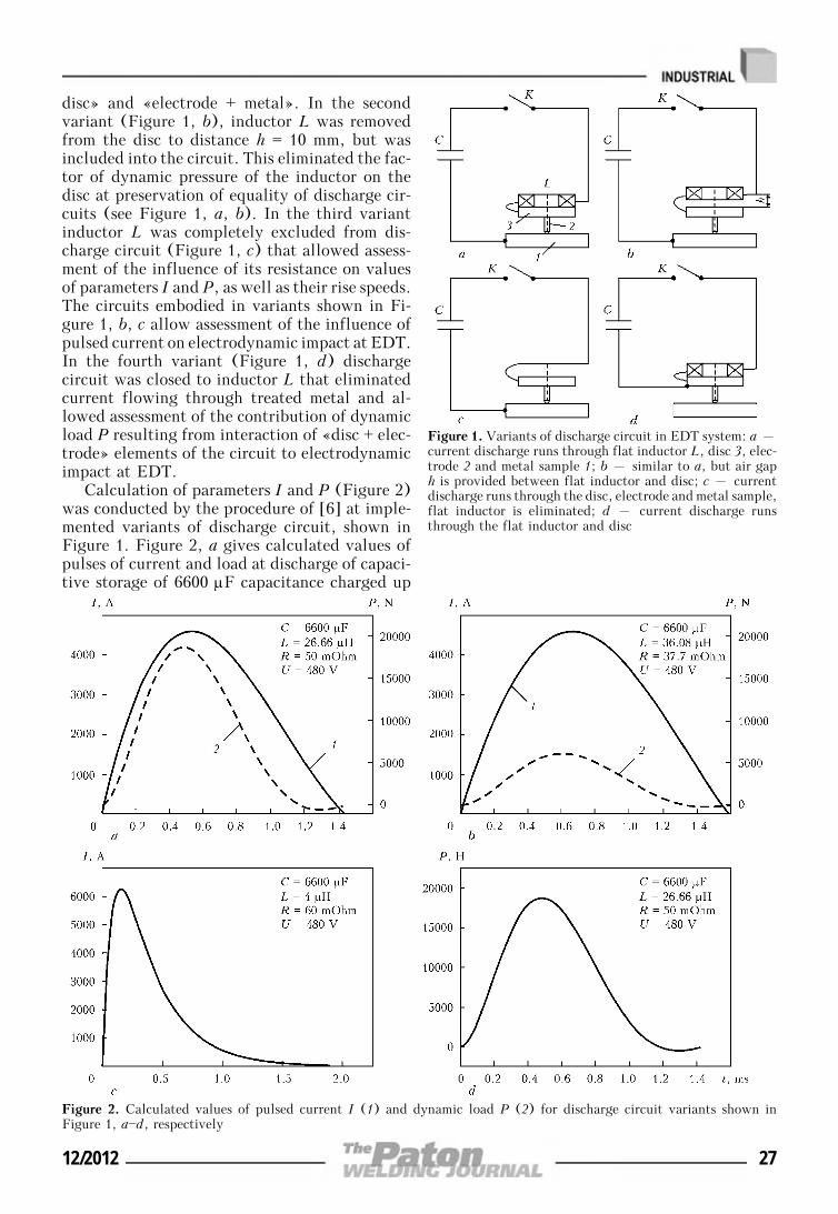
disc» and «electrode + metal». In the secondvariant (Figure 1, b), inductor L was removedfrom the disc to distance h = 10 mm, but wasincluded into the circuit. This eliminated the fac-tor of dynamic pressure of the inductor on thedisc at preservation of equality of discharge cir-cuits (see Figure 1, a, b). In the third variantinductor L was completely excluded from dis-charge circuit (Figure 1, c) that allowed assess-ment of the influence of its resistance on valuesof parameters I and P, as well as their rise speeds.The circuits embodied in variants shown in Fi-gure 1, b, c allow assessment of the influence ofpulsed current on electrodynamic impact at EDT.In the fourth variant (Figure 1, d) dischargecircuit was closed to inductor L that eliminatedcurrent flowing through treated metal and al-lowed assessment of the contribution of dynamicload P resulting from interaction of «disc + elec-trode» elements of the circuit to electrodynamicimpact at EDT.
Calculation of parameters I and P (Figure 2)was conducted by the procedure of [6] at imple-mented variants of discharge circuit, shown inFigure 1. Figure 2, a gives calculated values ofpulses of current and load at discharge of capaci-tive storage of 6600 μF capacitance charged up
Figure 1. Variants of discharge circuit in EDT system: a –current discharge runs through flat inductor L, disc 3, elec-trode 2 and metal sample 1; b – similar to a, but air gaph is provided between flat inductor and disc; c – currentdischarge runs through the disc, electrode and metal sample,flat inductor is eliminated; d – current discharge runsthrough the flat inductor and disc
Figure 2. Calculated values of pulsed current I (1) and dynamic load P (2) for discharge circuit variants shown inFigure 1, a—d, respectively
12/2012 27
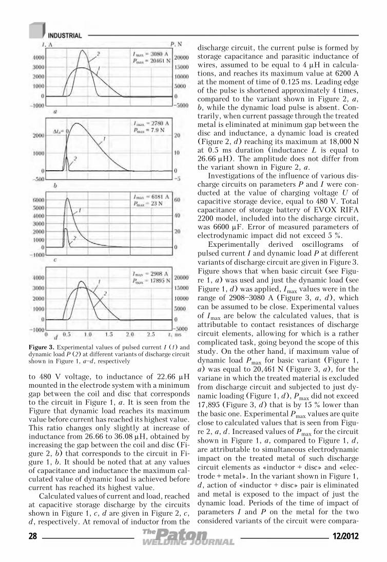
to 480 V voltage, to inductance of 22.66 μHmounted in the electrode system with a minimumgap between the coil and disc that correspondsto the circuit in Figure 1, a. It is seen from theFigure that dynamic load reaches its maximumvalue before current has reached its highest value.This ratio changes only slightly at increase ofinductance from 26.66 to 36.08 μH, obtained byincreasing the gap between the coil and disc (Fi-gure 2, b) that corresponds to the circuit in Fi-gure 1, b. It should be noted that at any valuesof capacitance and inductance the maximum cal-culated value of dynamic load is achieved beforecurrent has reached its highest value.
Calculated values of current and load, reachedat capacitive storage discharge by the circuitsshown in Figure 1, c, d are given in Figure 2, c,d, respectively. At removal of inductor from the
discharge circuit, the current pulse is formed bystorage capacitance and parasitic inductance ofwires, assumed to be equal to 4 μH in calcula-tions, and reaches its maximum value at 6200 Aat the moment of time of 0.125 ms. Leading edgeof the pulse is shortened approximately 4 times,compared to the variant shown in Figure 2, a,b, while the dynamic load pulse is absent. Con-trarily, when current passage through the treatedmetal is eliminated at minimum gap between thedisc and inductance, a dynamic load is created(Figure 2, d) reaching its maximum at 18,000 Nat 0.5 ms duration (inductance L is equal to26.66 μH). The amplitude does not differ fromthe variant shown in Figure 2, a.
Investigations of the influence of various dis-charge circuits on parameters P and I were con-ducted at the value of charging voltage U ofcapacitive storage device, equal to 480 V. Totalcapacitance of storage battery of EVOX RIFA2200 model, included into the discharge circuit,was 6600 μF. Error of measured parameters ofelectrodynamic impact did not exceed 5 %.
Experimentally derived oscillograms ofpulsed current I and dynamic load P at differentvariants of discharge circuit are given in Figure 3.Figure shows that when basic circuit (see Figu-re 1, a) was used and just the dynamic load (seeFigure 1, d) was applied, Imax values were in therange of 2908—3080 A (Figure 3, a, d), whichcan be assumed to be close. Experimental valuesof Imax are below the calculated values, that isattributable to contact resistances of dischargecircuit elements, allowing for which is a rathercomplicated task, going beyond the scope of thisstudy. On the other hand, if maximum value ofdynamic load Pmax for basic variant (Figure 1,a) was equal to 20,461 N (Figure 3, a), for thevariane in which the treated material is excludedfrom discharge circuit and subjected to just dy-namic loading (Figure 1, d), Pmax did not exceed17,895 (Figure 3, d) that is by 15 % lower thanthe basic one. Experimental Pmax values are quiteclose to calculated values that is seen from Figu-re 2, a, d. Increased values of Pmax for the circuitshown in Figure 1, a, compared to Figure 1, d,are attributable to simultaneous electrodynamicimpact on the treated metal of such dischargecircuit elements as «inductor + disc» and «elec-trode + metal». In the variant shown in Figure 1,d, action of «inductor + disc» pair is eliminatedand metal is exposed to the impact of just thedynamic load. Periods of the time of impact ofparameters I and P on the metal for the twoconsidered variants of the circuit were compara-
Figure 3. Experimental values of pulsed current I (1) anddynamic load P (2) at different variants of discharge circuitshown in Figure 1, a—d, respectively
28 12/2012
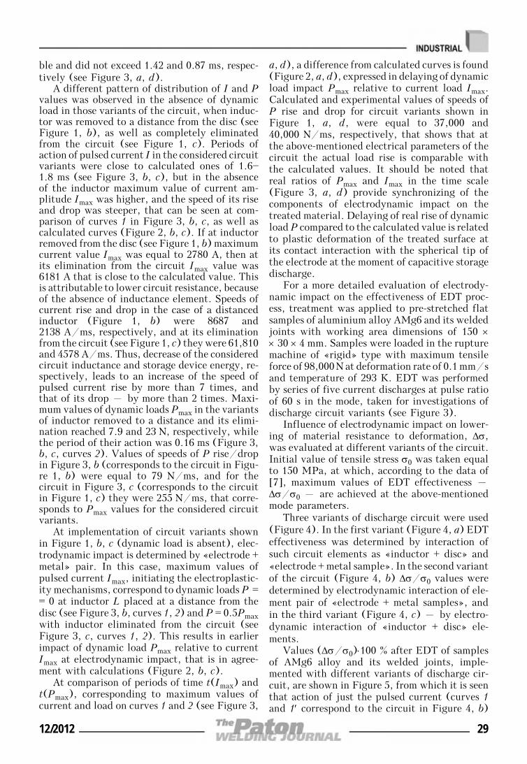
ble and did not exceed 1.42 and 0.87 ms, respec-tively (see Figure 3, a, d).
A different pattern of distribution of I and Pvalues was observed in the absence of dynamicload in those variants of the circuit, when induc-tor was removed to a distance from the disc (seeFigure 1, b), as well as completely eliminatedfrom the circuit (see Figure 1, c). Periods ofaction of pulsed current I in the considered circuitvariants were close to calculated ones of 1.6—1.8 ms (see Figure 3, b, c), but in the absenceof the inductor maximum value of current am-plitude Imax was higher, and the speed of its riseand drop was steeper, that can be seen at com-parison of curves 1 in Figure 3, b, c, as well ascalculated curves (Figure 2, b, c). If at inductorremoved from the disc (see Figure 1, b) maximumcurrent value Imax was equal to 2780 A, then atits elimination from the circuit Imax value was6181 A that is close to the calculated value. Thisis attributable to lower circuit resistance, becauseof the absence of inductance element. Speeds ofcurrent rise and drop in the case of a distancedinductor (Figure 1, b) were 8687 and2138 A/ms, respectively, and at its eliminationfrom the circuit (see Figure 1, c) they were 61,810and 4578 A/ms. Thus, decrease of the consideredcircuit inductance and storage device energy, re-spectively, leads to an increase of the speed ofpulsed current rise by more than 7 times, andthat of its drop – by more than 2 times. Maxi-mum values of dynamic loads Pmax in the variantsof inductor removed to a distance and its elimi-nation reached 7.9 and 23 N, respectively, whilethe period of their action was 0.16 ms (Figure 3,b, c, curves 2). Values of speeds of P rise/dropin Figure 3, b (corresponds to the circuit in Figu-re 1, b) were equal to 79 N/ms, and for thecircuit in Figure 3, c (corresponds to the circuitin Figure 1, c) they were 255 N/ms, that corre-sponds to Pmax values for the considered circuitvariants.
At implementation of circuit variants shownin Figure 1, b, c (dynamic load is absent), elec-trodynamic impact is determined by «electrode +metal» pair. In this case, maximum values ofpulsed current Imax, initiating the electroplastic-ity mechanisms, correspond to dynamic loads P == 0 at inductor L placed at a distance from thedisc (see Figure 3, b, curves 1, 2) and P = 0.5Pmaxwith inductor eliminated from the circuit (seeFigure 3, c, curves 1, 2). This results in earlierimpact of dynamic load Pmax relative to currentImax at electrodynamic impact, that is in agree-ment with calculations (Figure 2, b, c).
At comparison of periods of time t(Imax) andt(Pmax), corresponding to maximum values ofcurrent and load on curves 1 and 2 (see Figure 3,
a, d), a difference from calculated curves is found(Figure 2, a, d), expressed in delaying of dynamicload impact Pmax relative to current load Imax.Calculated and experimental values of speeds ofP rise and drop for circuit variants shown inFigure 1, a, d, were equal to 37,000 and40,000 N/ms, respectively, that shows that atthe above-mentioned electrical parameters of thecircuit the actual load rise is comparable withthe calculated values. It should be noted thatreal ratios of Pmax and Imax in the time scale(Figure 3, a, d) provide synchronizing of thecomponents of electrodynamic impact on thetreated material. Delaying of real rise of dynamicload P compared to the calculated value is relatedto plastic deformation of the treated surface atits contact interaction with the spherical tip ofthe electrode at the moment of capacitive storagedischarge.
For a more detailed evaluation of electrody-namic impact on the effectiveness of EDT proc-ess, treatment was applied to pre-stretched flatsamples of aluminium alloy AMg6 and its weldedjoints with working area dimensions of 150 ×× 30 × 4 mm. Samples were loaded in the rupturemachine of «rigid» type with maximum tensileforce of 98,000 N at deformation rate of 0.1 mm/sand temperature of 293 K. EDT was performedby series of five current discharges at pulse ratioof 60 s in the mode, taken for investigations ofdischarge circuit variants (see Figure 3).
Influence of electrodynamic impact on lower-ing of material resistance to deformation, Δσ,was evaluated at different variants of the circuit.Initial value of tensile stress σ0 was taken equalto 150 MPa, at which, according to the data of[7], maximum values of EDT effectiveness –Δσ/σ0 – are achieved at the above-mentionedmode parameters.
Three variants of discharge circuit were used(Figure 4). In the first variant (Figure 4, a) EDTeffectiveness was determined by interaction ofsuch circuit elements as «inductor + disc» and«electrode + metal sample». In the second variantof the circuit (Figure 4, b) Δσ/σ0 values weredetermined by electrodynamic interaction of ele-ment pair of «electrode + metal samples», andin the third variant (Figure 4, c) – by electro-dynamic interaction of «inductor + disc» ele-ments.
Values (Δσ/σ0)⋅100 % after EDT of samplesof AMg6 alloy and its welded joints, imple-mented with different variants of discharge cir-cuit, are shown in Figure 5, from which it is seenthat action of just the pulsed current (curves 1and 1′ correspond to the circuit in Figure 4, b)
12/2012 29
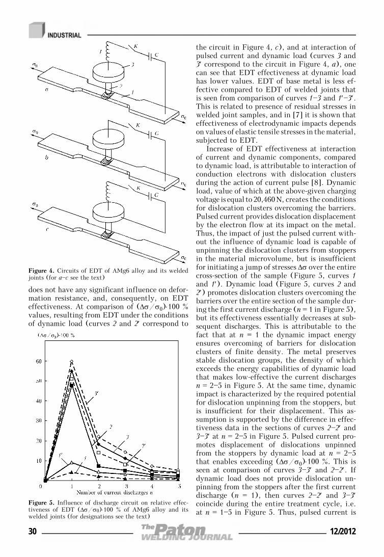
does not have any significant influence on defor-mation resistance, and, consequently, on EDTeffectiveness. At comparison of (Δσ/σ0)⋅100 %values, resulting from EDT under the conditionsof dynamic load (curves 2 and 2′ correspond to
the circuit in Figure 4, c), and at interaction ofpulsed current and dynamic load (curves 3 and3′ correspond to the circuit in Figure 4, a), onecan see that EDT effectiveness at dynamic loadhas lower values. EDT of base metal is less ef-fective compared to EDT of welded joints thatis seen from comparison of curves 1—3 and 1′—3′.This is related to presence of residual stresses inwelded joint samples, and in [7] it is shown thateffectiveness of electrodynamic impacts dependson values of elastic tensile stresses in the material,subjected to EDT.
Increase of EDT effectiveness at interactionof current and dynamic components, comparedto dynamic load, is attributable to interaction ofconduction electrons with dislocation clustersduring the action of current pulse [8]. Dynamicload, value of which at the above-given chargingvoltage is equal to 20,460 N, creates the conditionsfor dislocation clusters overcoming the barriers.Pulsed current provides dislocation displacementby the electron flow at its impact on the metal.Thus, the impact of just the pulsed current with-out the influence of dynamic load is capable ofunpinning the dislocation clusters from stoppersin the material microvolume, but is insufficientfor initiating a jump of stresses Δσ over the entirecross-section of the sample (Figure 5, curves 1and 1′). Dynamic load (Figure 5, curves 2 and2′) promotes dislocation clusters overcoming thebarriers over the entire section of the sample dur-ing the first current discharge (n = 1 in Figure 5),but its effectiveness essentially decreases at sub-sequent discharges. This is attributable to thefact that at n = 1 the dynamic impact energyensures overcoming of barriers for dislocationclusters of finite density. The metal preservesstable dislocation groups, the density of whichexceeds the energy capabilities of dynamic loadthat makes low-effective the current dischargesn = 2—5 in Figure 5. At the same time, dynamicimpact is characterized by the required potentialfor dislocation unpinning from the stoppers, butis insufficient for their displacement. This as-sumption is supported by the difference in effec-tiveness data in the sections of curves 2—2′ and3—3′ at n = 2—5 in Figure 5. Pulsed current pro-motes displacement of dislocations unpinnedfrom the stoppers by dynamic load at n = 2—5that enables exceeding (Δσ/σ0)⋅100 %. This isseen at comparison of curves 3—3′ and 2—2′. Ifdynamic load does not provide dislocation un-pinning from the stoppers after the first currentdischarge (n = 1), then curves 2—2′ and 3—3′coincide during the entire treatment cycle, i.e.at n = 1—5 in Figure 5. Thus, pulsed current is
Figure 4. Circuits of EDT of AMg6 alloy and its weldedjoints (for a—c see the text)
Figure 5. Influence of discharge circuit on relative effec-tiveness of EDT (Δσ/σ0)⋅100 % of AMg6 alloy and itswelded joints (for designations see the text)
30 12/2012
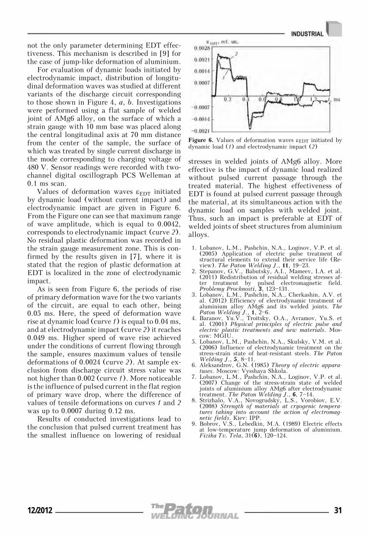
not the only parameter determining EDT effec-tiveness. This mechanism is described in [9] forthe case of jump-like deformation of aluminium.
For evaluation of dynamic loads initiated byelectrodynamic impact, distribution of longitu-dinal deformation waves was studied at differentvariants of the discharge circuit correspondingto those shown in Figure 4, a, b. Investigationswere performed using a flat sample of weldedjoint of AMg6 alloy, on the surface of which astrain gauge with 10 mm base was placed alongthe central longitudinal axis at 70 mm distancefrom the center of the sample, the surface ofwhich was treated by single current discharge inthe mode corresponding to charging voltage of480 V. Sensor readings were recorded with two-channel digital oscillograph PCS Welleman at0.1 ms scan.
Values of deformation waves εEDT initiatedby dynamic load (without current impact) andelectrodynamic impact are given in Figure 6.From the Figure one can see that maximum rangeof wave amplitude, which is equal to 0.0042,corresponds to electrodynamic impact (curve 2).No residual plastic deformation was recorded inthe strain gauge measurement zone. This is con-firmed by the results given in [7], where it isstated that the region of plastic deformation atEDT is localized in the zone of electrodynamicimpact.
As is seen from Figure 6, the periods of riseof primary deformation wave for the two variantsof the circuit, are equal to each other, being0.05 ms. Here, the speed of deformation waverise at dynamic load (curve 1) is equal to 0.04 ms,and at electrodynamic impact (curve 2) it reaches0.049 ms. Higher speed of wave rise achievedunder the conditions of current flowing throughthe sample, ensures maximum values of tensiledeformations of 0.0024 (curve 2). At sample ex-clusion from discharge circuit stress value wasnot higher than 0.002 (curve 1). More noticeableis the influence of pulsed current in the flat regionof primary wave drop, where the difference ofvalues of tensile deformations on curves 1 and 2was up to 0.0007 during 0.12 ms.
Results of conducted investigations lead tothe conclusion that pulsed current treatment hasthe smallest influence on lowering of residual
stresses in welded joints of AMg6 alloy. Moreeffective is the impact of dynamic load realizedwithout pulsed current passage through thetreated material. The highest effectiveness ofEDT is found at pulsed current passage throughthe material, at its simultaneous action with thedynamic load on samples with welded joint.Thus, such an impact is preferable at EDT ofwelded joints of sheet structures from aluminiumalloys.
1. Lobanov, L.M., Pashchin, N.A., Loginov, V.P. et al.(2005) Application of electric pulse treatment ofstructural elements to extend their service life (Re-view). The Paton Welding J., 11, 19—23.
2. Stepanov, G.V., Babutsky, A.I., Mameev, I.A. et al.(2011) Redistribution of residual welding stresses af-ter treatment by pulsed electromagnetic field.Problemy Prochnosti, 3, 123—131.
3. Lobanov, L.M., Pashchin, N.A., Cherkashin, A.V. etal. (2012) Efficiency of electrodynamic treatment ofaluminium alloy AMg6 and its welded joints. ThePaton Welding J., 1, 2—6.
4. Baranov, Yu.V., Troitsky, O.A., Avramov, Yu.S. etal. (2001) Physical principles of electric pulse andelectric plastic treatments and new materials. Mos-cow: MGIU.
5. Lobanov, L.M., Pashchin, N.A., Skulsky, V.M. et al.(2006) Influence of electrodynamic treatment on thestress-strain state of heat-resistant steels. The PatonWelding J., 5, 8—11.
6. Aleksandrov, G.N. (1985) Theory of electric appara-tuses. Moscow: Vysshaya Shkola.
7. Lobanov, L.M., Pashchin, N.A., Loginov, V.P. et al.(2007) Change of the stress-strain state of weldedjoints of aluminium alloy AMg6 after electrodynamictreatment. The Paton Welding J., 6, 7—14.
8. Strizhalo, V.A., Novogrudsky, L.S., Vorobiov, E.V.(2008) Strength of materials at cryogenic tempera-tures taking into account the action of electromag-netic fields. Kiev: IPP.
9. Bobrov, V.S., Lebedkin, M.A. (1989) Electric effectsat low-temperature jump deformation of aluminium.Fizika Tv. Tela, 31(6), 120—124.
Figure 6. Values of deformation waves εEDT initiated bydynamic load (1) and electrodynamic impact (2)
12/2012 31
PECULIARITIES OF LASER-ARC WELDINGOF TITANIUM ALLOYS
V.D. SHELYAGIN, V.Yu. KHASKIN, S.V. AKHONIN, V.Yu. BELOUS, I.K. PETRICHENKO, A.V. SIORA,A.N. PALAGESHA and R.V. SELIN
E.O. Paton Electric Welding Institute, NASU, Kiev, Ukraine
Methods were developed, and parameters were selected for hybrid laser-arc welding. It was establishedthat hybrid laser-arc welding allows producing joints on low and medium titanium alloys with propertiesthat are not inferior to those of the base metal. Impact toughness of the hybrid laser-arc welded joints onhigh titanium alloy T110 is much higher than that of the laser welded joints.
Keywo r d s : hybrid laser-arc welding, laser radia-tion, tungsten-electrode arc, titanium alloys, experi-ments, parameters, metallography, structures, mechanicalproperties
At present titanium alloys are applied for fabri-cation of critical structures operating in aero-space engineering, chemical industry, instrumentmaking and ship building. They are used to manu-facture such critical parts as stringer panels foraircraft, rocket components, tanks for chemicalindustry, casing parts, etc. [1]. Often the designsolutions these parts are based on require the useof welding processes. In practice, more than 90 %of all the welds are made by argon-arc and elec-tron beam welding [2].
However, these welding methods have draw-backs of both technological (low power densityin the arc discharge plasma) and economical char-acter (high cost even at small dimensions of themajority of vacuum chambers for electron beamwelding). Laser welding has been gaining accep-tance lately, which is due to its advantages, suchas high power density in the laser beam, highproductivity and precision of processing [3]. Asubstantial drawback of the process of laser weld-ing is a high cost of the equipment involved. Asshown in study [4], one of the ways of reducingthis indicator is partial replacement of the laserpower by the arc one. Moreover, laser weldingalso has some technological limitations relatedto a high reflection power of surfaces of manystructural metals and alloys. However, it can beovercome by using the hybrid laser-arc process.
The work on hybrid laser-arc welding of steelsand aluminium alloys has been performed forabout three decades (e.g. [5]). The discussionsare underway for the last ten years concerningthe possibility of applying it for titanium alloys[6], and corresponding experimental data have
been accumulated. The issue of the highest cur-rent importance is determination of the effect ofthe thermal cycle of hybrid laser-arc welding onproperties of the joints on high-strength titaniumalloys, for example, such as T110. In particular,under conditions of the experiment described instudy [7], laser welding of alloy T110 led todeterioration of its mechanical properties com-pared to the base metal.
The purpose of the present study was to in-vestigate peculiarities of laser-arc welding ofjoints on titanium alloys, such as low titaniumalloy VT6 and high-strength alloy T110, as wellas to evaluate mechanical properties of the re-sulting welded joints.
To solve this problem, the authors imple-mented the flowchart of the hybrid laser-arcwelding process shown in Figure 1. The radiationsource was Nd:YAG-laser DY 044 (Rofin Sinar,Germany) with a power of up to 4.4 kW andwavelength of 1.06 μm, and the welding currentsource was power supply VDU-601 UZ for auto-matic TIG welding. According to this flowchart,the tungsten electrode is located ahead of thelaser beam. This combination of laser and TIGwelding makes it possible to increase the pene-trating power of the welding process and permitsa simple feed of the filler wire to the weldingzone. To implement this flowchart, a weldinghead was developed to provide feed of laser beam1 focused by the lens (focal distance – 300 mm)and tungsten electrode 7 (diameter – 5 mm,sharpening angle – 30°) to a certain point onthe surface of specimen 5 being welded. The dis-tance from the electrode tip to the surface of thewelded specimen was set at about 3 mm. Thedistance from the exit section of the lower partof the welding head to the specimen was thesame. Deepening of the focal plane of the laser
© V.D. SHELYAGIN, V.Yu. KHASKIN, S.V. AKHONIN, V.Yu. BELOUS, I.K. PETRICHENKO, A.V. SIORA, A.N. PALAGESHA and R.V. SELIN, 2012
32 12/2012
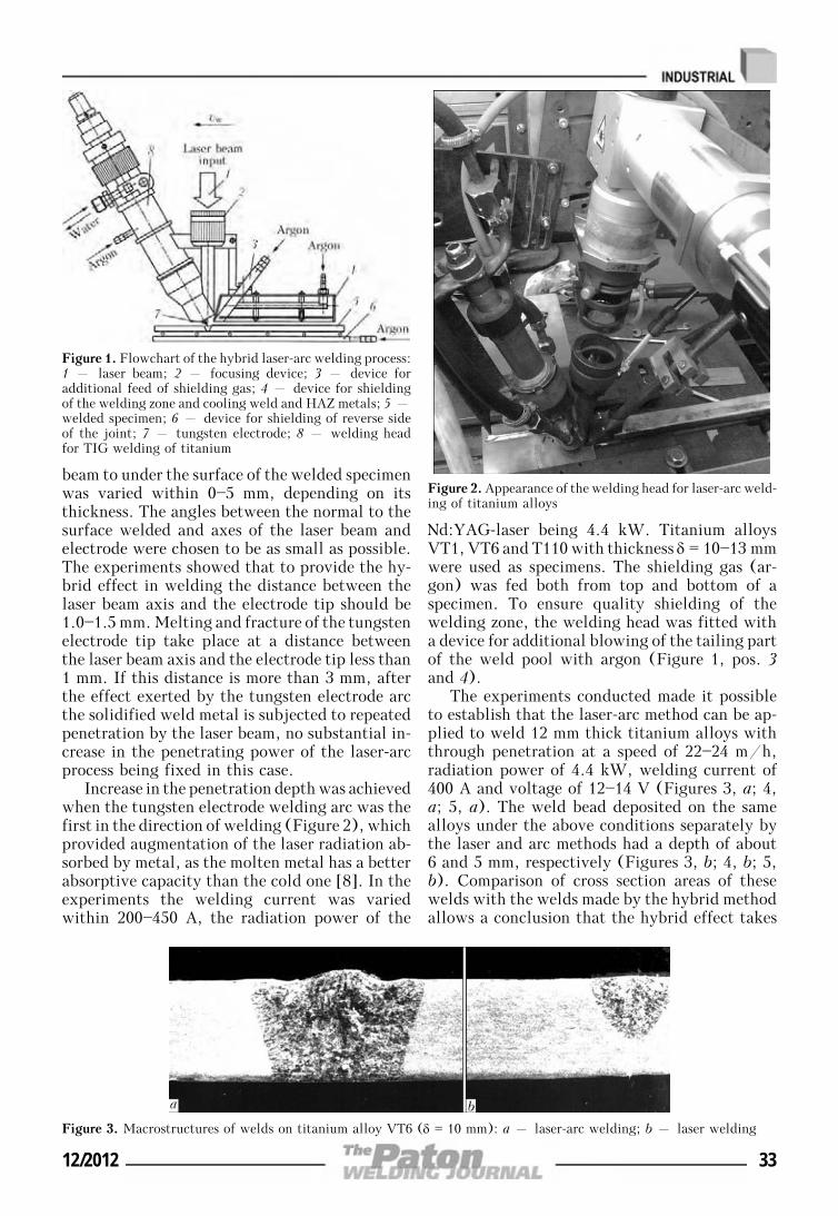
beam to under the surface of the welded specimenwas varied within 0—5 mm, depending on itsthickness. The angles between the normal to thesurface welded and axes of the laser beam andelectrode were chosen to be as small as possible.The experiments showed that to provide the hy-brid effect in welding the distance between thelaser beam axis and the electrode tip should be1.0—1.5 mm. Melting and fracture of the tungstenelectrode tip take place at a distance betweenthe laser beam axis and the electrode tip less than1 mm. If this distance is more than 3 mm, afterthe effect exerted by the tungsten electrode arcthe solidified weld metal is subjected to repeatedpenetration by the laser beam, no substantial in-crease in the penetrating power of the laser-arcprocess being fixed in this case.
Increase in the penetration depth was achievedwhen the tungsten electrode welding arc was thefirst in the direction of welding (Figure 2), whichprovided augmentation of the laser radiation ab-sorbed by metal, as the molten metal has a betterabsorptive capacity than the cold one [8]. In theexperiments the welding current was variedwithin 200—450 A, the radiation power of the
Nd:YAG-laser being 4.4 kW. Titanium alloysVT1, VT6 and T110 with thickness δ = 10—13 mmwere used as specimens. The shielding gas (ar-gon) was fed both from top and bottom of aspecimen. To ensure quality shielding of thewelding zone, the welding head was fitted witha device for additional blowing of the tailing partof the weld pool with argon (Figure 1, pos. 3and 4).
The experiments conducted made it possibleto establish that the laser-arc method can be ap-plied to weld 12 mm thick titanium alloys withthrough penetration at a speed of 22—24 m/h,radiation power of 4.4 kW, welding current of400 A and voltage of 12—14 V (Figures 3, a; 4,a; 5, a). The weld bead deposited on the samealloys under the above conditions separately bythe laser and arc methods had a depth of about6 and 5 mm, respectively (Figures 3, b; 4, b; 5,b). Comparison of cross section areas of thesewelds with the welds made by the hybrid methodallows a conclusion that the hybrid effect takes
Figure 1. Flowchart of the hybrid laser-arc welding process:1 – laser beam; 2 – focusing device; 3 – device foradditional feed of shielding gas; 4 – device for shieldingof the welding zone and cooling weld and HAZ metals; 5 –welded specimen; 6 – device for shielding of reverse sideof the joint; 7 – tungsten electrode; 8 – welding headfor TIG welding of titanium
Figure 2. Appearance of the welding head for laser-arc weld-ing of titanium alloys
Figure 3. Macrostructures of welds on titanium alloy VT6 (δ = 10 mm): a – laser-arc welding; b – laser welding
12/2012 33
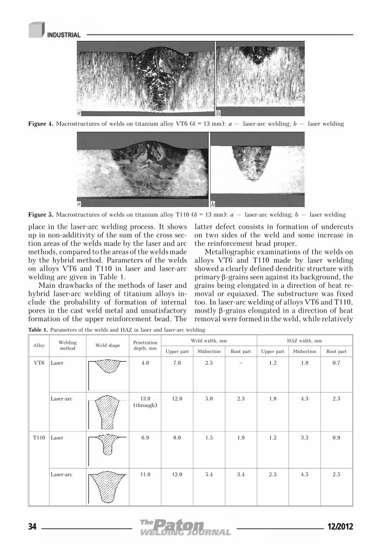
place in the laser-arc welding process. It showsup in non-additivity of the sum of the cross sec-tion areas of the welds made by the laser and arcmethods, compared to the areas of the welds madeby the hybrid method. Parameters of the weldson alloys VT6 and T110 in laser and laser-arcwelding are given in Table 1.
Main drawbacks of the methods of laser andhybrid laser-arc welding of titanium alloys in-clude the probability of formation of internalpores in the cast weld metal and unsatisfactoryformation of the upper reinforcement bead. The
latter defect consists in formation of undercutson two sides of the weld and some increase inthe reinforcement bead proper.
Metallographic examinations of the welds onalloys VT6 and T110 made by laser weldingshowed a clearly defined dendritic structure withprimary β-grains seen against its background, thegrains being elongated in a direction of heat re-moval or equiaxed. The substructure was fixedtoo. In laser-arc welding of alloys VT6 and T110,mostly β-grains elongated in a direction of heatremoval were formed in the weld, while relatively
Figure 4. Macrostructures of welds on titanium alloy VT6 (δ = 13 mm): a – laser-arc welding; b – laser welding
Table 1. Parameters of the welds and HAZ in laser and laser-arc welding
AlloyWeldingmethod
Weld shapePenetrationdepth, mm
Weld width, mm HAZ width, mm
Upper part Midsection Root part Upper part Midsection Root part
VT6 Laser 4.0 7.0 2.5 — 1.2 1.8 0.7
Laser-arc 13.0(through)
12.0 5.0 2.3 1.8 4.3 2.3
Т110 Laser 6.9 8.0 1.5 1.9 1.2 3.3 0.9
Laser-arc 11.0 12.0 5.4 3.4 2.3 4.5 2.5
Figure 5. Macrostructures of welds on titanium alloy T110 (δ = 13 mm): a – laser-arc welding; b – laser welding
34 12/2012
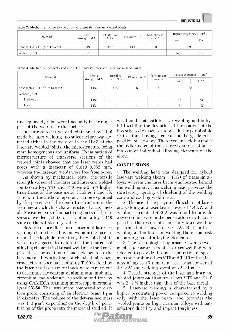
fine equiaxed grains were fixed only in the upperpart of the weld near the surface.
In contrast to the welded joints on alloy T110made by laser welding, no substructure was de-tected either in the weld or in the HAZ of thelaser-arc welded joints, the microstructure beingmore homogeneous and uniform. Examination ofmicrostructure of transverse sections of thewelded joints showed that the laser welds hadpores with a diameter of 0.010—0.035 mm,whereas the laser-arc welds were free from pores.
As shown by mechanical tests, the tensilestrength values of the laser and laser-arc weldedjoints on alloys VT6 and T110 were 2—4 % higherthan those of the base metal (Tables 2 and 3),which, in the authors’ opinion, can be explainedby the presence of the dendritic structure in theweld metal, which is characteristic of a cast met-al. Measurements of impact toughness of the la-ser-arc welded joints on titanium alloy T110showed the satisfactory values.
Because of peculiarities of laser and laser-arcwelding characterised by an evaporating mecha-nism of the keyhole formation, the welded jointswere investigated to determine the content ofalloying elements in the cast weld metal and com-pare it to the content of such elements in thebase metal. Investigations of chemical microhet-erogeneity in specimens of alloy T100 welded bythe laser and laser-arc methods were carried outto determine the content of aluminium, niobium,zirconium, molybdenum, vanadium and iron byusing CAMECA scanning microscope-microana-lyser SX-50. The instrument comprised an elec-tron probe consisting of an electron beam 1 μmin diameter. The volume of the determined masswas 1—3 μm3, depending on the depth of pene-tration of the probe into the material studied. It
was found that both in laser welding and in hy-brid welding the deviation of the content of theinvestigated elements was within the permissiblescatter for alloying elements in the grade com-position of the alloy. Therefore, in welding underthe indicated conditions there is no risk of burn-ing out of individual alloying elements of thealloy.
CONCLUSIONS
1. The welding head was designed for hybridlaser-arc welding (beam + TIG) of titanium al-loys, wherein the laser beam was located behindthe welding arc. This welding head provides thesatisfactory quality of shielding of the weldingzone and cooling weld metal.
2. The use of the proposed flowchart of laser-arc welding at a laser beam power of 4.4 kW andwelding current of 400 A was found to providea twofold increase in the penetration depth, com-pared to the results of using only laser weldingperformed at a power of 4.4 kW. Both in laserwelding and in laser-arc welding there is no riskof burning out of alloying elements.
3. The technological approaches were devel-oped, and parameters of laser-arc welding wereselected to provide through penetration of speci-mens of titanium alloys VT6 and T110 with thick-ness of up to 13 mm at a laser beam power of4.4 kW and welding speed of 22—24 m/h.
4. Tensile strength of the laser and laser-arcwelded joints on titanium alloys VT6 and T110was 2—4 % higher than that of the base metal.
5. Laser-arc welding is characterised by ahigher penetrating power compared to weldingonly with the laser beam, and provides thewelded joints on high titanium alloys with sat-isfactory ductility and impact toughness.
Table 2. Mechanical properties of alloy VT6 and its laser-arc welded joints
MaterialTensile
strength, MPaDuctility limit,
MPaElongation, %
Reduction inarea, %
Impact toughness, J/cm2
Weld HAZ
Base metal VT6 (δ = 13 mm) 888 815 13.6 30 39
Welded joint 911 — — — 54 32
Table 3. Mechanical properties of alloy T110 and its laser and laser-arc welded joints
MaterialTensile
strength, MPaDuctility
limit, MPaElongation, %
Reduction inarea, %
Impact toughness, J/cm2
Weld HAZ
Base metal T110 (δ = 13 mm) 1130 999 6 5 38
Welded joint:
laser-arc 1180 — — — 15 23
laser 1131 — — — 6 13
12/2012 35
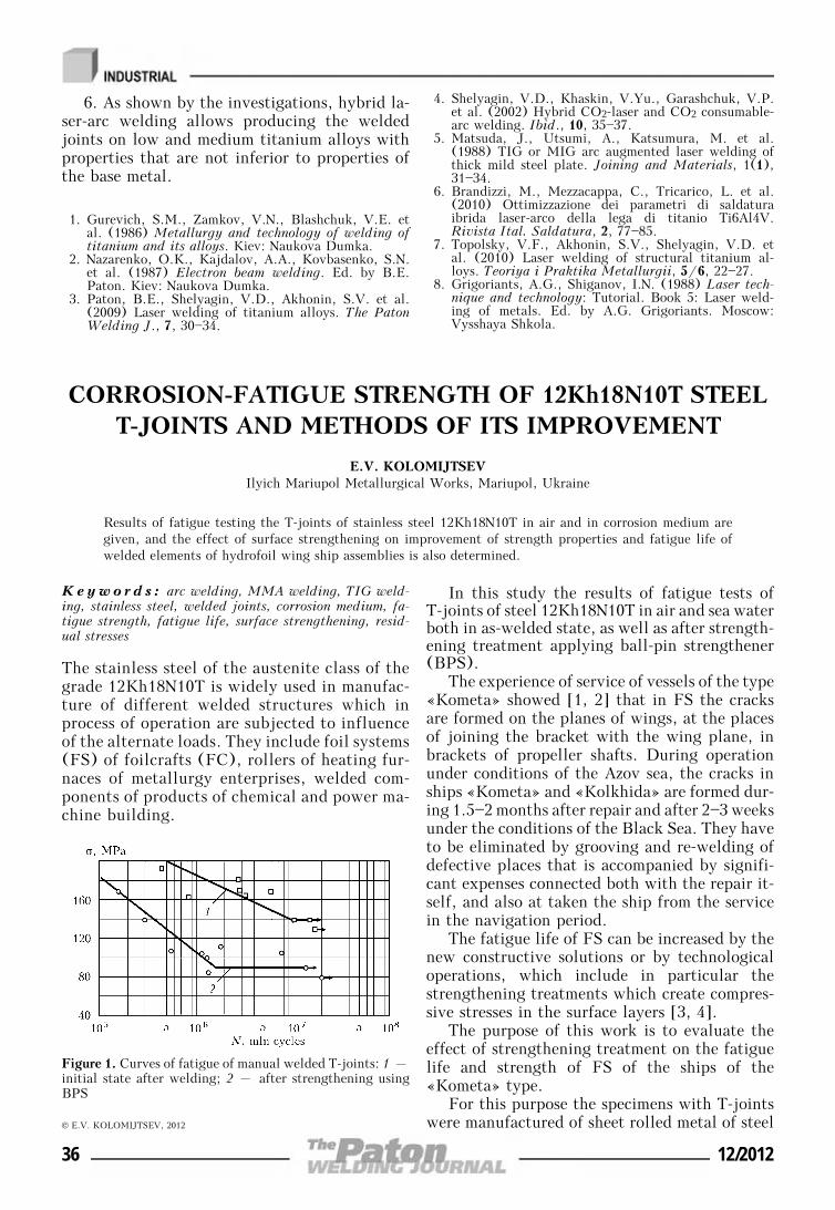
6. As shown by the investigations, hybrid la-ser-arc welding allows producing the weldedjoints on low and medium titanium alloys withproperties that are not inferior to properties ofthe base metal.
1. Gurevich, S.M., Zamkov, V.N., Blashchuk, V.E. etal. (1986) Metallurgy and technology of welding oftitanium and its alloys. Kiev: Naukova Dumka.
2. Nazarenko, O.K., Kajdalov, A.A., Kovbasenko, S.N.et al. (1987) Electron beam welding. Ed. by B.E.Paton. Kiev: Naukova Dumka.
3. Paton, B.E., Shelyagin, V.D., Akhonin, S.V. et al.(2009) Laser welding of titanium alloys. The PatonWelding J., 7, 30—34.
4. Shelyagin, V.D., Khaskin, V.Yu., Garashchuk, V.P.et al. (2002) Hybrid CO2-laser and CO2 consumable-arc welding. Ibid., 10, 35—37.
5. Matsuda, J., Utsumi, A., Katsumura, M. et al.(1988) TIG or MIG arc augmented laser welding ofthick mild steel plate. Joining and Materials, 1(1),31—34.
6. Brandizzi, M., Mezzacappa, C., Tricarico, L. et al.(2010) Ottimizzazione dei parametri di saldaturaibrida laser-arco della lega di titanio Ti6Al4V.Rivista Ital. Saldatura, 2, 77—85.
7. Topolsky, V.F., Akhonin, S.V., Shelyagin, V.D. etal. (2010) Laser welding of structural titanium al-loys. Teoriya i Praktika Metallurgii, 5/6, 22—27.
8. Grigoriants, A.G., Shiganov, I.N. (1988) Laser tech-nique and technology: Tutorial. Book 5: Laser weld-ing of metals. Ed. by A.G. Grigoriants. Moscow:Vysshaya Shkola.
CORROSION-FATIGUE STRENGTH OF 12Kh18N10T STEELT-JOINTS AND METHODS OF ITS IMPROVEMENT
E.V. KOLOMIJTSEVIlyich Mariupol Metallurgical Works, Mariupol, Ukraine
Results of fatigue testing the T-joints of stainless steel 12Kh18N10T in air and in corrosion medium aregiven, and the effect of surface strengthening on improvement of strength properties and fatigue life ofwelded elements of hydrofoil wing ship assemblies is also determined.
Keywo r d s : arc welding, MMA welding, TIG weld-ing, stainless steel, welded joints, corrosion medium, fa-tigue strength, fatigue life, surface strengthening, resid-ual stresses
The stainless steel of the austenite class of thegrade 12Kh18N10T is widely used in manufac-ture of different welded structures which inprocess of operation are subjected to influenceof the alternate loads. They include foil systems(FS) of foilcrafts (FC), rollers of heating fur-naces of metallurgy enterprises, welded com-ponents of products of chemical and power ma-chine building.
In this study the results of fatigue tests ofT-joints of steel 12Kh18N10T in air and sea waterboth in as-welded state, as well as after strength-ening treatment applying ball-pin strengthener(BPS).
The experience of service of vessels of the type«Kometa» showed [1, 2] that in FS the cracksare formed on the planes of wings, at the placesof joining the bracket with the wing plane, inbrackets of propeller shafts. During operationunder conditions of the Azov sea, the cracks inships «Kometa» and «Kolkhida» are formed dur-ing 1.5—2 months after repair and after 2—3 weeksunder the conditions of the Black Sea. They haveto be eliminated by grooving and re-welding ofdefective places that is accompanied by signifi-cant expenses connected both with the repair it-self, and also at taken the ship from the servicein the navigation period.
The fatigue life of FS can be increased by thenew constructive solutions or by technologicaloperations, which include in particular thestrengthening treatments which create compres-sive stresses in the surface layers [3, 4].
The purpose of this work is to evaluate theeffect of strengthening treatment on the fatiguelife and strength of FS of the ships of the«Kometa» type.
For this purpose the specimens with T-jointswere manufactured of sheet rolled metal of steel
Figure 1. Curves of fatigue of manual welded T-joints: 1 –initial state after welding; 2 – after strengthening usingBPS
© E.V. KOLOMIJTSEV, 2012
36 12/2012
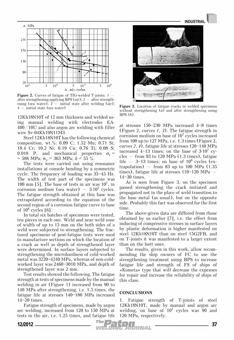
12Kh18N10T of 12 mm thickness and welded us-ing manual welding with electrodes EA-400/10U and also argon arc welding with fillerwire Sv-04Kh19N11M3.
Steel 12Kh18N10T has the following chemicalcomposition, wt.%: 0.09 C; 1.52 Mn; 0.71 Si;18.4 Cr; 10.2 Ni; 0.19 Cu; 0.76 Ti; 0.08 S;0.018 P, and mechanical properties σt == 588 MPa; σy = 363 MPa; δ = 55 %.
The tests were carried out using resonanceinstallations at console bending by a symmetriccycle. The frequency of loading was 35—45 Hz.The width of test part of the specimens was100 mm [5]. The base of tests in air was 107, incorrosion medium (sea water) – 3⋅107 cycles.The fatigue strength obtained at this base wasextrapolated according to the equation of thesecond region of a corrosion fatigue curve to baseof 108 cycles [6].
In total six batches of specimens were tested,ten pieces in each one. Weld and near-weld zoneof width of up to 15 mm on the both sides of aweld were subjected to strengthening. The frac-tured specimens of post-fatigue tests were usedto manufacture sections on which the location ofa crack as well as depth of strengthened layerwere determined. In surface layers subjected tostrengthening the microhardness of cold-workedmetal was 3220—4240 MPa, whereas of non-cold-worked layer was 2460—3010 MPa, and depth ofstrengthened layer was 2 mm.
Test results showed the following. The fatiguestrength at tests of specimens made by the manualwelding in air (Figure 1) increased from 90 to140 MPa after strengthening, i.e. 1.5 times, thefatigue life at stresses 140—180 MPa increased14—20 times.
Fatigue strength of specimens, made by argonarc welding, increased from 120 to 150 MPa attests in the air, i.e. 1.25 times, and fatigue life
at stresses 150—230 MPa increased 4—8 times(Figure 2, curves 1, 3). The fatigue strength incorrosion medium on base of 107 cycles increasedfrom 100 up to 127 MPa, i.e. 1.3 times (Figure 2,curves 2, 4), fatigue life at stresses 120—140 MPaincreased 4—13 times; on the base of 3⋅107 cy-cles – from 93 to 120 MPa (1.3 times), fatiguelife – 3—13 times; on base of 108 cycles (ex-trapolation) – from 83 up to 100 MPa (1.35times), fatigue life at stresses 110—120 MPa –14—30 times.
As is seen from Figure 3, on the specimenpassed strengthening the crack initiated andpropagated not in the place of weld transition tothe base metal (as usual), but on the oppositeside. Probably this fact was observed for the firsttime.
The above-given data are differed from thoseobtained by us earlier [7], i.e. the effect frominducing of compressive stresses in surface layersby plastic deformation is higher manifested onsteel 12Kh18N10T than on steel 15G2FB, andon T-joints it was manifested to a larger extentthan on the butt ones.
The results, given in this work, allow recom-mending the ship owners of FC to use thestrengthening treatment using BPS to increasefatigue life and strength of FS of ships of«Kometa» type that will decrease the expensesfor repair and increase the reliability of ships ofthis class.
CONCLUSIONS
1. Fatigue strength of T-joints of steel12Kh18N10T, made by manual and argon arcwelding, on base of 107 cycles was 90 and120 MPa, respectively.
Figure 2. Curves of fatigue of TIG-welded T-joints: 1 –after strengthening applying BPS (air); 2 – after strength-ening (sea water); 3 – initial state after welding (air);4 – initial state (sea water) Figure 3. Location of fatigue cracks in welded specimens
without strengthening (a) and after strengthening usingBPS (b)
12/2012 37
2. Corrosion-fatigue strength of 12Kh18N10Tsteel T-joints, made by argon arc welding, onbase of 107 cycles was 100, on base of 108 –83 MPa.
3. Plastic deformation using BPS increasedthe fatigue strength of steel 12Kh18N10T T-joints up to 140 and 150 MPa for manual andargon arc welding, respectively: fatigue life –4—8 times for TIG-welded joints and 14—20 timesfor manual welded joints; corrosion-fatiguestrength was increased up to 127 MPa on baseof 107 cycles and up to 110 MPa on base of 108
cycles, i.e. 1.3 times; fatigue life at stresses 110—120 MPa was 14—30 times increased.
4. Hardening treatment of FC FS using BPScan be recommended to implementation at shiprepair enterprises.
1. Ziganchenko, P.P., Kuzovenkov, B.P., Tarasov, I.K.(1981) Hydrofoil ships (design and strength). Lenin-grad: Sudostroenie.
2. Kuzovenkov, B.P. (1968) Some informations aboutdamageability of foil systems. In: Trudy NTO Sud-proma, Issue 101.
3. Stepanov, V.G., Klestov, M.I. (1977) Surfacestrengthening of hull structures. Leningrad: Sudo-stroenie.
4. Olejnik, N.V., Kychin, V.P., Lugovskoj, A.L. (1984)Surface dynamic strengthening of machine parts.Kiev: Tekhnika.
5. Kolomijtsev, E.V., Serenko, A.N. (1985) Experimen-tal evaluation of fatigue resistance of low alloy steelbutt joints in corrosion medium. Avtomatich.Svarka, 4, 49—52.
6. Kolomijtsev, E.V., Karpov, I.V. (1986) To choice oftest base of hull plates on fatigue corrosion. Sudo-stroenie, 10, 39—40.
7. Kolomijtsev, E.V., Serenko, A.N. (1990) Influence ofultrasonic and laser treatments on fatigue resistanceof welded butt joints in air and corrosive medium.Avtomatich. Svarka, 11, 13—15.
INFLUENCE OF CONTENT OF IRON POWDERAND COMPOUNDS OF ALKALI METALS
IN THE COMPOSITION OF ELECTRODE COATINGON THEIR SANITARY-HYGIENIC CHARACTERISTICS
I.K. POKHODNYA, I.R. YAVDOSHCHIN and I.P. GUBENYAE.O. Paton Electric Welding Institute, NASU, Kiev, Ukraine
The dependence of the specific precipitations and chemical composition of a hard component of weldingaerosol on content of iron powder in electrode coating was established. The effect of content of potassiumcompounds in coating of rutile and basic electrodes on their sanitary-hygienic characteristics was considered.
Keywo r d s : manual arc welding, electrodes, elec-trode coating, welding aerosol, coating composition,sanitary-hygienic characteristics, hard component, spe-cific precipitations
The manual arc welding with coated electrodesis challenging today and according to the fore-casts of the specialists [1, 2] it will continue itsexistence due to a number of advantages, suchas relatively moderate price of the process andconsumable materials, possibility of welding in
all positions and in hard-to-access places, lack ofrigid requirements to welder skills. At the sametime, already more than 50 years the searches forways to improve the sanitary-hygienic charac-teristics of electrodes are being continued.
The factors were determined influencing theevolution of aerosol [3], which consists of a gas-likecomponent of welding aerosol (GCWA) and a hardcomponent of welding aerosol (HCWA). One ofthe main factors defining the level of specific pre-cipitations and chemical composition of HCWA iscomposition of electrode coating as far as duringheating and melting it is the main source of aerosol,i.e. 35—70 % of the total volume depending on thetype of electrode coating [3, 4].
The iron powder, widely used in productionof coated electrodes, allows enhancing labor pro-ductivity of welder, decreasing the cost of weld-ing works, improving welding-technologicalproperties of electrodes [5]. The increase of pro-ductivity is achieved due to increase of transfer© I.K. POKHODNYA, I.R. YAVDOSHCHIN and I.P. GUBENYA, 2012
Table 1. Conditions of welding using coated electrodes of DZ se-ries
Electrode index Uw, V
DZ-0 26—28
DZ-1 26—28
DZ-2 25—27
DZ-3 24—26
Note. Welding current of 180 A.
38 12/2012
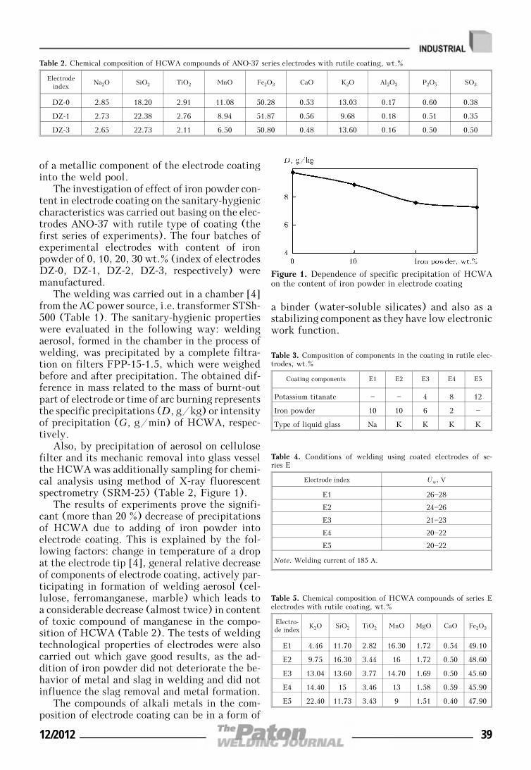
of a metallic component of the electrode coatinginto the weld pool.
The investigation of effect of iron powder con-tent in electrode coating on the sanitary-hygieniccharacteristics was carried out basing on the elec-trodes ANO-37 with rutile type of coating (thefirst series of experiments). The four batches ofexperimental electrodes with content of ironpowder of 0, 10, 20, 30 wt.% (index of electrodesDZ-0, DZ-1, DZ-2, DZ-3, respectively) weremanufactured.
The welding was carried out in a chamber [4]from the AC power source, i.e. transformer STSh-500 (Table 1). The sanitary-hygienic propertieswere evaluated in the following way: weldingaerosol, formed in the chamber in the process ofwelding, was precipitated by a complete filtra-tion on filters FPP-15-1.5, which were weighedbefore and after precipitation. The obtained dif-ference in mass related to the mass of burnt-outpart of electrode or time of arc burning representsthe specific precipitations (D, g/kg) or intensityof precipitation (G, g/min) of HCWA, respec-tively.
Also, by precipitation of aerosol on cellulosefilter and its mechanic removal into glass vesselthe HCWA was additionally sampling for chemi-cal analysis using method of X-ray fluorescentspectrometry (SRM-25) (Table 2, Figure 1).
The results of experiments prove the signifi-cant (more than 20 %) decrease of precipitationsof HCWA due to adding of iron powder intoelectrode coating. This is explained by the fol-lowing factors: change in temperature of a dropat the electrode tip [4], general relative decreaseof components of electrode coating, actively par-ticipating in formation of welding aerosol (cel-lulose, ferromanganese, marble) which leads toa considerable decrease (almost twice) in contentof toxic compound of manganese in the compo-sition of HCWA (Table 2). The tests of weldingtechnological properties of electrodes were alsocarried out which gave good results, as the ad-dition of iron powder did not deteriorate the be-havior of metal and slag in welding and did notinfluence the slag removal and metal formation.
The compounds of alkali metals in the com-position of electrode coating can be in a form of
a binder (water-soluble silicates) and also as astabilizing component as they have low electronicwork function.
Figure 1. Dependence of specific precipitation of HCWAon the content of iron powder in electrode coating
Table 2. Chemical composition of HCWA compounds of ANO-37 series electrodes with rutile coating, wt.%
Electrodeindex
Na2O SiO2 TiO2 MnO Fe2O3 CaO K2O Al2O3 P2O5 SO3
DZ-0 2.85 18.20 2.91 11.08 50.28 0.53 13.03 0.17 0.60 0.38
DZ-1 2.73 22.38 2.76 8.94 51.87 0.56 9.68 0.18 0.51 0.35
DZ-3 2.65 22.73 2.11 6.50 50.80 0.48 13.60 0.16 0.50 0.50
Table 3. Composition of components in the coating in rutile elec-trodes, wt.%
Coating components E1 E2 E3 E4 E5
Potassium titanate — — 4 8 12
Iron powder 10 10 6 2 —
Type of liquid glass Na K K K K
Table 4. Conditions of welding using coated electrodes of se-ries E
Electrode index Uw, V
E1 26—28
E2 24—26
E3 21—23
E4 20—22
E5 20—22
Note. Welding current of 185 A.
Table 5. Chemical composition of HCWA compounds of series Eelectrodes with rutile coating, wt.%
Electro-de index
K2O SiO2 TiO2 MnO MgO CaO Fe2O3
E1 4.46 11.70 2.82 16.30 1.72 0.54 49.10
E2 9.75 16.30 3.44 16 1.72 0.50 48.60
E3 13.04 13.60 3.77 14.70 1.69 0.50 45.60
E4 14.40 15 3.46 13 1.58 0.59 45.90
E5 22.40 11.73 3.43 9 1.51 0.40 47.90
12/2012 39
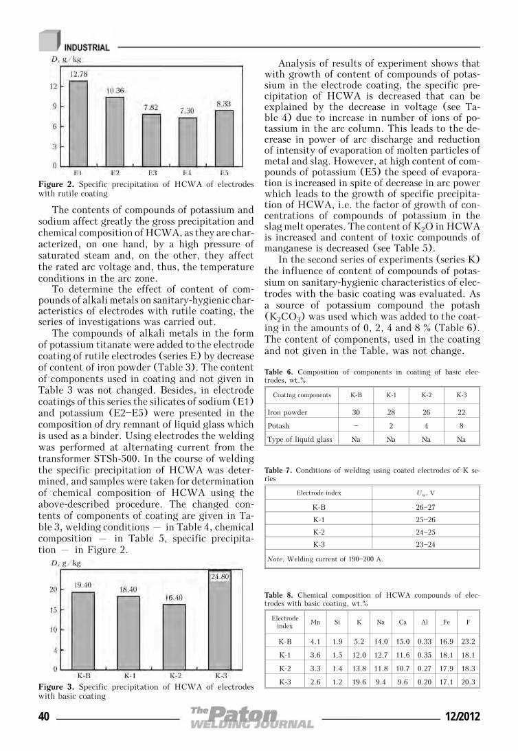
The contents of compounds of potassium andsodium affect greatly the gross precipitation andchemical composition of HCWA, as they are char-acterized, on one hand, by a high pressure ofsaturated steam and, on the other, they affectthe rated arc voltage and, thus, the temperatureconditions in the arc zone.
To determine the effect of content of com-pounds of alkali metals on sanitary-hygienic char-acteristics of electrodes with rutile coating, theseries of investigations was carried out.
The compounds of alkali metals in the formof potassium titanate were added to the electrodecoating of rutile electrodes (series E) by decreaseof content of iron powder (Table 3). The contentof components used in coating and not given inTable 3 was not changed. Besides, in electrodecoatings of this series the silicates of sodium (E1)and potassium (E2—E5) were presented in thecomposition of dry remnant of liquid glass whichis used as a binder. Using electrodes the weldingwas performed at alternating current from thetransformer STSh-500. In the course of weldingthe specific precipitation of HCWA was deter-mined, and samples were taken for determinationof chemical composition of HCWA using theabove-described procedure. The changed con-tents of components of coating are given in Ta-ble 3, welding conditions – in Table 4, chemicalcomposition – in Table 5, specific precipita-tion – in Figure 2.
Analysis of results of experiment shows thatwith growth of content of compounds of potas-sium in the electrode coating, the specific pre-cipitation of HCWA is decreased that can beexplained by the decrease in voltage (see Ta-ble 4) due to increase in number of ions of po-tassium in the arc column. This leads to the de-crease in power of arc discharge and reductionof intensity of evaporation of molten particles ofmetal and slag. However, at high content of com-pounds of potassium (E5) the speed of evapora-tion is increased in spite of decrease in arc powerwhich leads to the growth of specific precipita-tion of HCWA, i.e. the factor of growth of con-centrations of compounds of potassium in theslag melt operates. The content of K2O in HCWAis increased and content of toxic compounds ofmanganese is decreased (see Table 5).
In the second series of experiments (series K)the influence of content of compounds of potas-sium on sanitary-hygienic characteristics of elec-trodes with the basic coating was evaluated. Asa source of potassium compound the potash(K2CO3) was used which was added to the coat-ing in the amounts of 0, 2, 4 and 8 % (Table 6).The content of components, used in the coatingand not given in the Table, was not change.
Figure 2. Specific precipitation of HCWA of electrodeswith rutile coating
Figure 3. Specific precipitation of HCWA of electrodeswith basic coating
Table 6. Composition of components in coating of basic elec-trodes, wt.%
Coating components K-B K-1 K-2 K-3
Iron powder 30 28 26 22
Potash — 2 4 8
Type of liquid glass Na Na Na Na
Table 7. Conditions of welding using coated electrodes of K se-ries
Electrode index Uw, V
K-B 26—27
K-1 25—26
K-2 24—25
K-3 23—24
Note. Welding current of 190—200 A.
Table 8. Chemical composition of HCWA compounds of elec-trodes with basic coating, wt.%
Electrodeindex
Mn Si K Na Ca Al Fe F
K-B 4.1 1.9 5.2 14.0 15.0 0.33 16.9 23.2
K-1 3.6 1.5 12.0 12.7 11.6 0.35 18.1 18.1
K-2 3.3 1.4 13.8 11.8 10.7 0.27 17.9 18.3
K-3 2.6 1.2 19.6 9.4 9.6 0.20 17.1 20.3
40 12/2012
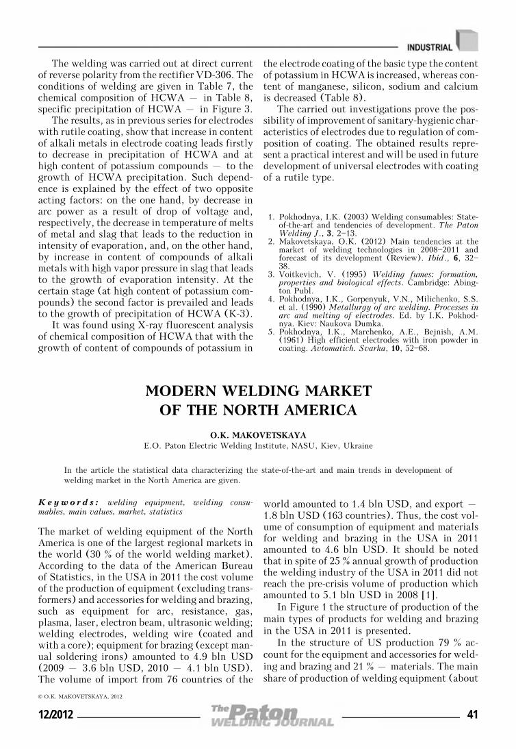
The welding was carried out at direct currentof reverse polarity from the rectifier VD-306. Theconditions of welding are given in Table 7, thechemical composition of HCWA – in Table 8,specific precipitation of HCWA – in Figure 3.
The results, as in previous series for electrodeswith rutile coating, show that increase in contentof alkali metals in electrode coating leads firstlyto decrease in precipitation of HCWA and athigh content of potassium compounds – to thegrowth of HCWA precipitation. Such depend-ence is explained by the effect of two oppositeacting factors: on the one hand, by decrease inarc power as a result of drop of voltage and,respectively, the decrease in temperature of meltsof metal and slag that leads to the reduction inintensity of evaporation, and, on the other hand,by increase in content of compounds of alkalimetals with high vapor pressure in slag that leadsto the growth of evaporation intensity. At thecertain stage (at high content of potassium com-pounds) the second factor is prevailed and leadsto the growth of precipitation of HCWA (K-3).
It was found using X-ray fluorescent analysisof chemical composition of HCWA that with thegrowth of content of compounds of potassium in
the electrode coating of the basic type the contentof potassium in HCWA is increased, whereas con-tent of manganese, silicon, sodium and calciumis decreased (Table 8).
The carried out investigations prove the pos-sibility of improvement of sanitary-hygienic char-acteristics of electrodes due to regulation of com-position of coating. The obtained results repre-sent a practical interest and will be used in futuredevelopment of universal electrodes with coatingof a rutile type.
1. Pokhodnya, I.K. (2003) Welding consumables: State-of-the-art and tendencies of development. The PatonWelding J., 3, 2—13.
2. Makovetskaya, O.K. (2012) Main tendencies at themarket of welding technologies in 2008—2011 andforecast of its development (Review). Ibid., 6, 32—38.
3. Voitkevich, V. (1995) Welding fumes: formation,properties and biological effects. Cambridge: Abing-ton Publ.
4. Pokhodnya, I.K., Gorpenyuk, V.N., Milichenko, S.S.et al. (1990) Metallurgy of arc welding. Processes inarc and melting of electrodes. Ed. by I.K. Pokhod-nya. Kiev: Naukova Dumka.
5. Pokhodnya, I.K., Marchenko, A.E., Bejnish, A.M.(1961) High efficient electrodes with iron powder incoating. Avtomatich. Svarka, 10, 52—68.
MODERN WELDING MARKETOF THE NORTH AMERICA
O.K. MAKOVETSKAYAE.O. Paton Electric Welding Institute, NASU, Kiev, Ukraine
In the article the statistical data characterizing the state-of-the-art and main trends in development ofwelding market in the North America are given.
Keywo r d s : welding equipment, welding consu-mables, main values, market, statistics
The market of welding equipment of the NorthAmerica is one of the largest regional markets inthe world (30 % of the world welding market).According to the data of the American Bureauof Statistics, in the USA in 2011 the cost volumeof the production of equipment (excluding trans-formers) and accessories for welding and brazing,such as equipment for arc, resistance, gas,plasma, laser, electron beam, ultrasonic welding;welding electrodes, welding wire (coated andwith a core); equipment for brazing (except man-ual soldering irons) amounted to 4.9 bln USD(2009 – 3.6 bln USD, 2010 – 4.1 bln USD).The volume of import from 76 countries of the
world amounted to 1.4 bln USD, and export –1.8 bln USD (163 countries). Thus, the cost vol-ume of consumption of equipment and materialsfor welding and brazing in the USA in 2011amounted to 4.6 bln USD. It should be notedthat in spite of 25 % annual growth of productionthe welding industry of the USA in 2011 did notreach the pre-crisis volume of production whichamounted to 5.1 bln USD in 2008 [1].
In Figure 1 the structure of production of themain types of products for welding and brazingin the USA in 2011 is presented.
In the structure of US production 79 % ac-count for the equipment and accessories for weld-ing and brazing and 21 % – materials. The mainshare of production of welding equipment (about
© O.K. MAKOVETSKAYA, 2012
12/2012 41
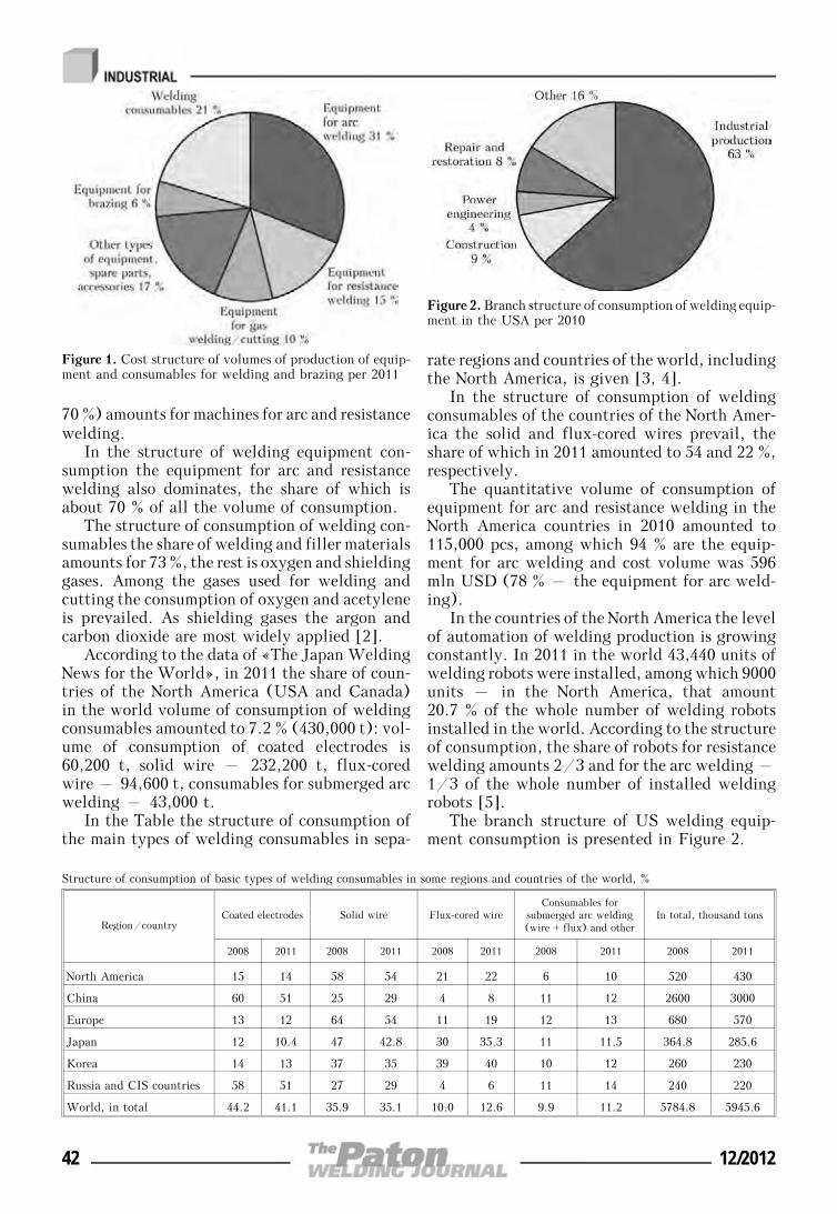
70 %) amounts for machines for arc and resistancewelding.
In the structure of welding equipment con-sumption the equipment for arc and resistancewelding also dominates, the share of which isabout 70 % of all the volume of consumption.
The structure of consumption of welding con-sumables the share of welding and filler materialsamounts for 73 %, the rest is oxygen and shieldinggases. Among the gases used for welding andcutting the consumption of oxygen and acetyleneis prevailed. As shielding gases the argon andcarbon dioxide are most widely applied [2].
According to the data of «The Japan WeldingNews for the World», in 2011 the share of coun-tries of the North America (USA and Canada)in the world volume of consumption of weldingconsumables amounted to 7.2 % (430,000 t): vol-ume of consumption of coated electrodes is60,200 t, solid wire – 232,200 t, flux-coredwire – 94,600 t, consumables for submerged arcwelding – 43,000 t.
In the Table the structure of consumption ofthe main types of welding consumables in sepa-
rate regions and countries of the world, includingthe North America, is given [3, 4].
In the structure of consumption of weldingconsumables of the countries of the North Amer-ica the solid and flux-cored wires prevail, theshare of which in 2011 amounted to 54 and 22 %,respectively.
The quantitative volume of consumption ofequipment for arc and resistance welding in theNorth America countries in 2010 amounted to115,000 pcs, among which 94 % are the equip-ment for arc welding and cost volume was 596mln USD (78 % – the equipment for arc weld-ing).
In the countries of the North America the levelof automation of welding production is growingconstantly. In 2011 in the world 43,440 units ofwelding robots were installed, among which 9000units – in the North America, that amount20.7 % of the whole number of welding robotsinstalled in the world. According to the structureof consumption, the share of robots for resistancewelding amounts 2/3 and for the arc welding –1/3 of the whole number of installed weldingrobots [5].
The branch structure of US welding equip-ment consumption is presented in Figure 2.
Structure of consumption of basic types of welding consumables in some regions and countries of the world, %
Region/countryCoated electrodes Solid wire Flux-cored wire
Consumables forsubmerged arc welding(wire + flux) and other
In total, thousand tons
2008 2011 2008 2011 2008 2011 2008 2011 2008 2011
North America 15 14 58 54 21 22 6 10 520 430
China 60 51 25 29 4 8 11 12 2600 3000
Europe 13 12 64 54 11 19 12 13 680 570
Japan 12 10.4 47 42.8 30 35.3 11 11.5 364.8 285.6
Korea 14 13 37 35 39 40 10 12 260 230
Russia and CIS countries 58 51 27 29 4 6 11 14 240 220
World, in total 44.2 41.1 35.9 35.1 10.0 12.6 9.9 11.2 5784.8 5945.6
Figure 1. Cost structure of volumes of production of equip-ment and consumables for welding and brazing per 2011
Figure 2. Branch structure of consumption of welding equip-ment in the USA per 2010
42 12/2012
According to the estimates of the AmericanWelding Society the growth of consumption ofwelding equipment in the USA in the nearestyears is expected in agricultural machine build-ing, road and bridge construction, railway andcommunication transport, power engineering,petrochemical industry (including constructionof oil and gas pipelines, tankers for transporta-tion of oil and gas).
It is predicted that in 2015 at annual growthby 6.4 % the cost volume of consumption of equip-ment and consumables for welding and brazingin the USA will reach 7.1 bln USD. In thebranches of industry the volume of consumptionof welding equipment will amount to 4.4 blnUSD, and in construction – 750 mln USD [6].
According to the data of the US Bureau ofStatistics about 970,000 of employers and spe-cialists-welders are engaged in the national econ-omy [7].
The basic manufacturers of welding equip-ment in the USA are:
• Lincoln Electric Holdings Inc. – the lead-ing world manufacturer of equipment and con-sumables for welding and brazing. It includesthe brands like Brastek, Harris. The companyhas 40 plants in 19 countries of the world andits distribution network comprises more than 160countries. The volume of sales of the companyin 2011 achieved 2.7 bln USD, which amountedto about 50 % of the total volume of sales at themarket of the USA and 16 % at the world marketof welding equipment. By the end of 2011 thecompany occupied the 1st place in the rating ofthe largest world manufacturers of weldingequipment [8];
• Illinois Tool Works – the largest diversifiedcompany. It comprises the brands like ITW,Miller Electric, Hobart, Bernard, Weldcraft,Jetline, Elga, Tian TVai, WIA. The productioncapacities and distribution network are located
in 57 countries of the world. The volume of salesin 2010 amounted to 15.9 bln USD, among which12 % cover welding consumables and equipment.According to the data of [9] it occupied the 3rdplace in the rating of the largest world manufac-turers of welding equipment;
• Thermadyne Holdings – the leading manu-facturer of gas-flame equipment in the USA. Itcomprises the brands like Thermadyne Indus-tries, Thermadyne Dynamics, Victor, Tweco, Ar-cair, Thermal Arc, Stoody, Turbo Torch, Fire-power and Cigweld. The production capacitiesand distribution network are located in the Amer-ica, Europe and Asia. The volume of salesamounted to 487.4 mln USD in 2010. Accordingto the data of [10] it occupied the 7th place inthe rating of the largest world manufacturers ofwelding equipment.
1. Value of shipments for product classes: 2010 and ear-lier years. Annual Survey of Manufactures. U.S. Cen-sus Bureau. http://www.census.gov
2. Welding and soldering equipment manufacturing in-dustry in the U.S. and its International Trade. Rep.www.Reportlinker.com
3. (2011) Worldwide demand for welding consumables.Worldwide demand for welding machines. The JapanWelding News for the World, 15(55), 5—6.
4. (2009) Worldwide demand for welding consumables.Worldwide demand for welding machines. Ibid.,13(47), 7.
5. (2012) General description for welding robots mar-ket. Ibid., 165(56), 6—7.
6. (2011) US demand for welding equipment & consu-mables to exceed $7 Billion (USD) in 2015. DailyNews, November, 11.
7. Occupation employment statistics. 51-4121 Welders.cutters. solders and brazers. 51-4122. Welding. sol-dering and brazing machine setters. operators andtenders. U.S. Census Bureau. http://www.cen-sus.gov
8. Lincoln Electric Holdings. Inc. 4Q 2011. Financialresults conference call. Febr. 17. 2012. http://www.lincolnelectric.com
9. ILLINOIS TOOL WORKS INC. 2011 Annual Re-port. http://www.itw.com
10. Thermadyne Holdings Corporation. Investor presenta-tion. Aug. 2011. http://www.thermadyne.com
12/2012 43
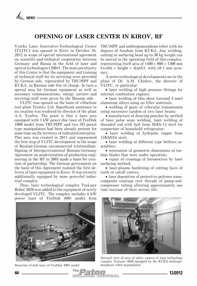
OPENING OF LASER CENTER IN KIROV, RF
Vyatka Laser Innovative-Technological Center(VLITC) was opened in Kirov in October 16,2012 in scope of special international agreementon scientific-and-technical cooperation betweenGermany and Russia in the field of laser andoptical technologies (2004). The main peculiarityof this Center is that the equipment and trainingof technical staff for its servicing were providedby German side, represented by TRUMPF andKUKA, to Russian side free of charge. In turn aspecial area for German equipment as well asnecessary communications, energy carriers andservicing staff were given by the Russian side.
VLITC was opened on the basis of «Machinetool plant Termit» Ltd. Significant assistance inits creation was rendered by director of the plantA.A. Tyuftin. The point is that a laser areaequipped with 1 kW power disc laser of TruDisk1000 model from TRUMPF and two 3D portaltype manipulators had been already present forsome time on the territory of indicated enterprise.This area was created in 2011 and representedthe first step of VLITC development in the scopeof Russian-German uncommercial relationships.Signing of Intergovernmental Russian-GermanyAgreement on modernization of production engi-neering in the RF in 2005 made a basis for crea-tion of partnership. The German government onthe basis of this Agreement realized the first de-livery of laser equipment in Kirov. It was recentlyadditionally equipped by more powerful indus-trial complex.
Thus, laser technological complex TruLaserRobot 5020 was added to the equipment of newlydeveloped VLITC. The complex includes 4 kWpower laser of TruDisk 4001 model from
TRUMPF and anthropomorphous robot with sixdegrees of freedom from KUKA. Any welding,cutting or surfacing head up to 30 kg weight canbe moved in the operating field of this complex,representing itself area of 1400 × 800 × 1200 mm(width × height × depth), with ±0.1 mm accu-racy.
A series technological developments are in theplans of Dr. A.M. Chirkov, the director ofVLITC, in particular:
• laser welding of high pressure fittings forinternal combustion engines;
• laser welding of thin sheet (around 3 mm)aluminum alloys using no filler materials;
• welding of gears of vehicular transmissionusing successive tandem of two laser beams;
• manufacture of drawing punches by methodof laser pulse seam welding, laser welding ofthreaded rod with ball from ShKh-15 steel forcompressor of household refrigerator;
• laser welding of hydraulic tappet from12KhN3A steel;
• laser welding of different type bellows as-semblies;
• restoration of geometric dimensions of tur-bine blades that were under operation;
• repair of crossings of locomotives by lasersurfacing method;
• laser-plasma hardening of cutting faces ofteeth of cutoff cutters;
• laser deposition of protective polymer nano-composite coatings over threads of pump-and-compressor tubing allowing approximately onetime increase of their service life;
Structure of disk laser of TruDisk 4001 model
Internal view of area of safety camera of laser technologycomplex TruLaser 5020 equipped by the KUKA anthropo-morphous robot-manipulator
44 12/2012
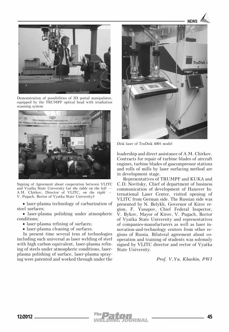
• laser-plasma technology of carburization ofsteel surfaces;
• laser-plasma polishing under atmosphericconditions;
• laser-plasma refining of surfaces;• laser-plasma cleaning of surfaces.In present time several tens of technologies
including such universal as laser welding of steelwith high carbon equivalent, laser-plasma refin-ing of steels under atmospheric conditions, laser-plasma polishing of surface, laser-plasma spray-ing were patented and worked through under the
leadership and direct assistance of A.M. Chirkov.Contracts for repair of turbine blades of aircraftengines, turbine blades of gascompressor stationsand rolls of mills by laser surfacing method arein development stage.
Representatives of TRUMPF and KUKA andC.D. Novitsky, Chief of department of businesscommunication of development of Hanover In-ternational Laser Center, visited opening ofVLITC from German side. The Russian side waspresented by N. Belykh, Governor of Kirov re-gion, F. Yusupov, Chief Federal Inspector,V. Bykov, Mayor of Kirov, V. Pugach, Rectorof Vyatka State University and representativesof companies-manufacturers as well as laser in-novation-and-technology centers from other re-gions of Russia. Bilateral agreement about co-operation and training of students was solemnlysigned by VLITC director and rector of VyatkaState University.
Prof. V.Yu. Khaskin, PWI
Demonstration of possibilities of 3D portal manipulator,equipped by the TRUMPF optical head with irradiationscanning system
Disk laser of TruDisk 4001 model
Signing of Agreement about cooperation between VLITCand Vyatka State University (at the table on the left –A.M. Chirkov, Director of VLITC, on the right –V. Pugach, Rector of Vyatka State University)
12/2012 45
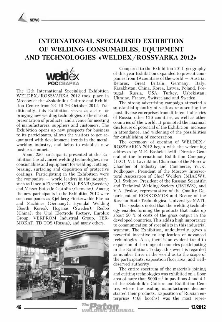
INTERNATIONAL SPECIALISED EXHIBITIONOF WELDING CONSUMABLES, EQUIPMENT
AND TECHNOLOGIES «WELDEX/ROSSVARKA 2012»
The 12th International Specialised ExhibitionWELDEX/ROSSVARKA 2012 took place inMoscow at the «Sokolniki» Culture and Exhibi-tion Centre from 23 till 26 October 2012. Tra-ditionally, this Exhibition serves as a site forbringing new welding technologies to the market,presentation of products, and a venue for meetingof manufacturers, suppliers and customers. TheExhibition opens up new prospects for businessto its participants, allows the visitors to get ac-quainted with development trends in the metal-working industry, and helps to establish newbusiness contacts.
About 250 participants presented at the Ex-hibition the advanced welding technologies, newconsumables and equipment for welding, cutting,brazing, surfacing and deposition of protectivecoatings. Participating in the Exhibition werethe companies – world leaders in the industry,such as Lincoln Electric (USA), ESAB (Sweden)and Messer Eutectic Castolin (Germany). Amongthe new participants in the Exhibition 2012 weresuch companies as Kjellberg Finsterwalde Plasmaand Machines (Germany), Hyundai Welding(South Korea), Hoganas (Sweden), Redbo(China), the Ural Electrode Factory, EuroluxGroup, VEKPROM Industrial Group, TER-MOKAT, TD TOS (Russia), and many others.
Compared to the Exhibition 2011, geographyof this year Exhibition expanded to present com-panies from 19 countries of the world – Austria,Belarus, Great Britain, Germany, Italy,Kazakhstan, China, Korea, Latvia, Poland, Por-tugal, Russia, USA, Turkey, Uzbekistan,Ukraine, France, Switzerland and Sweden.
The strong advertising campaign attracted asubstantial quantity of visitors representing themost diverse enterprises from different industriesof Russia, other CIS countries, as well as othercountries of the world. It promoted the maximaldisclosure of potential of the Exhibition, increasein attendance, and widening of the possibilitiesfor establishing of cooperation.
The ceremony of opening of WELDEX/ROSSVARKA 2012 began with the welcomingaddresses by M.E. Basheleishvili, Director Gen-eral of the International Exhibition Company(IEC), V.I. Lavrukhin, Chairman of the MoscowChamber of Industry and Commerce, Yu.K.Podkopaev, President of the Moscow Intersec-toral Association of Chief Welders (MIACW),O.I. Steklov, President of the Russian Scientificand Technical Welding Society (RSTWS), andV.A. Frolov, representative of the Quality De-partment of ROSKOSMOS and Rector of theRussian State Technological Universitys-MATI.
The speakers noted that the welding technol-ogy enables forming the products that make upabout 50 % of costs of the gross output in thedeveloped countries. This adds a high importanceto communication of specialists in this industrialsegment. The Exhibition, undoubtedly, gives apowerful incentive to application of advancedtechnologies. Also, there is an evident trend toexpansion of the range of countries participatingin the Exhibition. Today, this event is regardedas number three in the world as to the scope ofthe participants, exposition floor area, and well-deserved authority.
The entire spectrum of the materials joiningand cutting technologies was exhibited on a floorarea of more than 9000 m2 in pavilions 4 and 4.1of the «Sokolniki» Culture and Exhibition Cen-tre, where the leading manufacturers demon-strated their products. Exposition of Russian en-terprises (168 booths) was the most repre-
46 12/2012
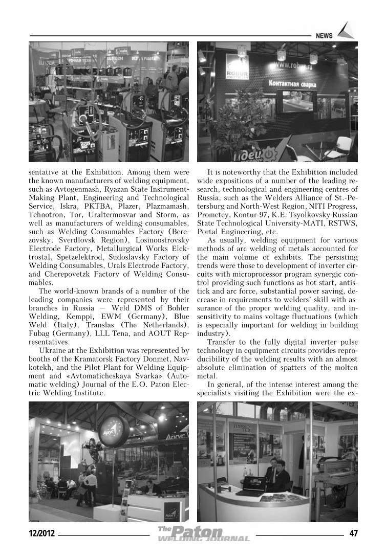
sentative at the Exhibition. Among them werethe known manufacturers of welding equipment,such as Avtogenmash, Ryazan State Instrument-Making Plant, Engineering and TechnologicalService, Iskra, PKTBA, Plazer, Plazmamash,Tehnotron, Tor, Uraltermosvar and Storm, aswell as manufacturers of welding consumables,such as Welding Consumables Factory (Bere-zovsky, Sverdlovsk Region), LosinoostrovskyElectrode Factory, Metallurgical Works Elek-trostal, Spetzelektrod, Sudoslavsky Factory ofWelding Consumables, Urals Electrode Factory,and Cherepovetzk Factory of Welding Consu-mables.
The world-known brands of a number of theleading companies were represented by theirbranches in Russia – Weld DMS of BohlerWelding, Kemppi, EWM (Germany), BlueWeld (Italy), Translas (The Netherlands),Fubag (Germany), LLL Tena, and AOUT Rep-resentatives.
Ukraine at the Exhibition was represented bybooths of the Kramatorsk Factory Donmet, Nav-kotekh, and the Pilot Plant for Welding Equip-ment and «Avtomaticheskaya Svarka» (Auto-matic welding) Journal of the E.O. Paton Elec-tric Welding Institute.
It is noteworthy that the Exhibition includedwide expositions of a number of the leading re-search, technological and engineering centres ofRussia, such as the Welders Alliance of St.-Pe-tersburg and North-West Region, NITI Progress,Prometey, Kontur-97, K.E. Tsyolkovsky RussianState Technological University-MATI, RSTWS,Portal Engineering, etc.
As usually, welding equipment for variousmethods of arc welding of metals accounted forthe main volume of exhibits. The persistingtrends were those to development of inverter cir-cuits with microprocessor program synergic con-trol providing such functions as hot start, antis-tick and arc force, substantial power saving, de-crease in requirements to welders’ skill with as-surance of the proper welding quality, and in-sensitivity to mains voltage fluctuations (whichis especially important for welding in buildingindustry).
Transfer to the fully digital inverter pulsetechnology in equipment circuits provides repro-ducibility of the welding results with an almostabsolute elimination of spatters of the moltenmetal.
In general, of the intense interest among thespecialists visiting the Exhibition were the ex-
12/2012 47
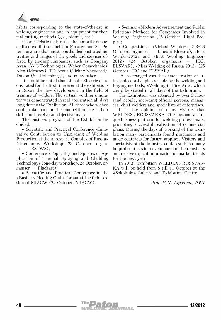
hibits corresponding to the state-of-the-art inwelding engineering and in equipment for ther-mal cutting methods (gas, plasma, etc.).
Characteristic features of the majority of spe-cialised exhibitions held in Moscow and St.-Pe-tersburg are that most booths demonstrated ac-tivities and ranges of the goods and services of-fered by trading companies, such as CompanyAvan, AVG Technologies, Weber Comechanics,Alex (Moscow), TD Argus (Nizhny Novgorod),Dukon (St.-Petersburg), and many others.
It should be noted that Lincoln Electric dem-onstrated for the first time ever at the exhibitionsin Russia the new development in the field oftraining of welders. The virtual welding simula-tor was demonstrated in real application all dayslong during the Exhibition. All those who wishedcould take part in the competition, test theirskills and receive an objective mark.
The business program of the Exhibition in-cluded:
• Scientific and Practical Conference «Inno-vative Contribution to Upgrading of WeldingProduction at the Aerospace Complex of Russia»(three-hours Workshop, 23 October, organ-iser – RSTWS);
• Conference «Topicality and Spheres of Ap-plication of Thermal Spraying and CladdingTechnology» (one-day workshop, 24 October, or-ganiser – Plackart);
• Scientific and Practical Conference in the«Business Meeting Club» format at the field ses-sion of MIACW (24 October, MIACW);
• Seminar «Modern Advertisement and PublicRelations Methods for Companies Involved inWelding Engineering (25 October, Right Peo-ple);
• Competitions: «Virtual Welders» (23—26October, organiser – Lincoln Electric), «BestWelder-2012» and «Best Welding Engineer-2012» (24 October, organisers – IEC,ELSVAR), «Miss Welding of Russia-2012» (25October, IEC and ELSVAR).
Also arranged was the demonstration of ar-tistic-decorative pieces made by the welding andforging methods, «Welding in Fine Art», whichcould be visited in all days of the Exhibition.
The Exhibition was attended by over 5 thou-sand people, including official persons, manag-ers, chief welders and specialists of enterprises.
It is the opinion of many visitors thatWELDEX/ROSSVARKA 2012 became a uni-que business platform for welding professionals,promoting successful realisation of commercialplans. During the days of working of the Exhi-bition many participants found purchasers andmade contracts for future supplies. Visitors andspecialists of the industry could establish manyhelpful contacts for development of their businessand receive topical information on market trendsfor the next year.
In 2013, Exhibition WELDEX/ROSSVAR-KA will be held from 8 till 11 October at the«Sokolniki» Culture and Exhibition Centre.
Prof. V.N. Lipodaev, PWI
48 12/2012
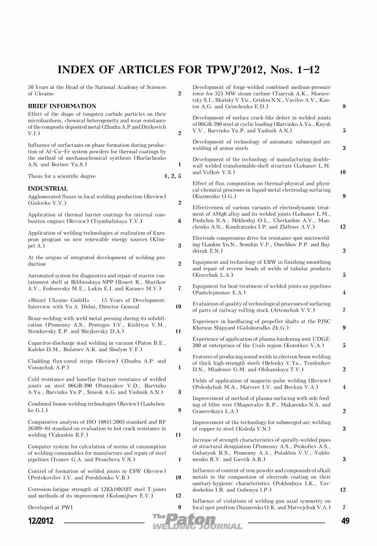
INDEX OF ARTICLES FOR TPWJ’2012, Nos. 1—1250 Years at the Head of the National Academy of Sciencesof Ukraine 2
BRIEF INFORMATIONEffect of the shape of tungsten carbide particles on theirmicrohardness, chemical heterogeneity and wear resistanceof the composite deposited metal (Zhudra A.P.and DzykovichV.I.) 2
Influence of surfactants on phase formation during produc-tion of Al—Cu—Fe system powders for thermal coatings bythe method of mechanochemical synthesis (BurlachenkoA.N. and Borisov Yu.S.) 1
Thesis for a scientific degree 1, 2, 5
INDUSTRIALAgglomerated fluxes in local welding production (Review)(Golovko V.V.) 2
Application of thermal barrier coatings for internal com-bustion engines (Review) (Tsymbalistaya T.V.) 6
Application of welding technologies at realization of Euro-pean program on new renewable energy sources (Klim-pel A.) 3
At the origins of integrated development of welding pro-duction 2
Automated system for diagnostics and repair of reactor con-tainment shell at Bilibinskaya NPP (Rosert R., ShutikovA.V., Fedosovsky M.E., Lukin E.I. and Karasev M.V.) 7
«Binzel Ukraine GmbH» – 15 Years of Development:Interview with Yu.A. Didus, Director General 10
Braze-welding with weld metal peening during its solidifi-cation (Pismenny A.S., Pentegov I.V., Kislitsyn V.M.,Stemkovsky E.P. and Shejkovsky D.A.) 11
Capacitor-discharge stud welding in vacuum (Paton B.E.,Kaleko D.M., Bulatsev A.R. and Shulym V.F.) 4
Cladding flux-cored strips (Review) (Zhudra A.P. andVoronchuk A.P.) 1
Cold resistance and lamellar fracture resistance of weldedjoints on steel 06GB-390 (Poznyakov V.D., BarvinkoA.Yu., Barvinko Yu.P., Sineok A.G. and Yashnik A.N.) 3
Combined fusion welding technologies (Review) (Lashchen-ko G.I.) 8
Comparative analysis of ISO 18841:2005 standard and RF26389—84 standard on evaluation to hot crack resistance inwelding (Yakushin B.F.) 11
Computer system for calculation of norms of consumptionof welding consumables for manufacture and repair of steelpipelines (Ivanov G.A. and Proncheva V.N.) 1
Control of formation of welded joints in ESW (Review)(Protokovilov I.V. and Porokhonko V.B.) 10
Corrosion-fatigue strength of 12Kh18N10T steel T-jointsand methods of its improvement (Kolomijtsev E.V.) 12
Developed at PWI 9
Development of forge-welded combined medium-pressurerotor for 325 MW steam turbine (Tsaryuk A.K., Morave-tsky S.I., Skulsky V.Yu., Grishin N.N., Vavilov A.V., Kan-tor A.G. and Grinchenko E.D.) 8
Development of surface crack-like defect in welded jointsof 06GB-390 steel at cyclic loading (Barvinko A.Yu., KnyshV.V., Barvinko Yu.P. and Yashnik A.N.) 5
Development of technology of automatic submerged arcwelding of armor steels 3
Development of the technology of manufacturing double-wall welded transformable-shell structure (Lobanov L.M.and Volkov V.S.) 10
Effect of flux composition on thermal-physical and physi-cal-chemical processes in liquid-metal electroslag surfacing(Kuzmenko O.G.) 9
Effectiveness of various variants of electrodynamic treat-ment of AMg6 alloy and its welded joints (Lobanov L.M.,Pashchin N.A., Mikhoduj O.L., Cherkashin A.V., Man-chenko A.N., Kondratenko I.P. and Zhiltsov A.V.) 12
Electrode compression drive for resistance spot microweld-ing (Lankin Yu.N., Semikin V.F., Osechkov P.P. and Baj-shtruk E.N.) 2
Equipment and technology of EBW in finishing smoothingand repair of reverse beads of welds of tubular products(Kravchuk L.A.) 5
Equipment for heat treatment of welded joints on pipelines(Pantelejmonov E.A.) 4
Evaluation of quality of technological processes of surfacingof parts of railway rolling stock (Artemchuk V.V.) 7
Experience in hardfacing of propeller shafts at the PJSCKherson Shipyard (Goloborodko Zh.G.) 9
Experience of application of plasma hardening unit UDGZ-200 at enterprises of the Urals region (Korotkov V.A.) 5
Features of producing sound welds in electron beam weldingof thick high-strength steels (Belenky V.Ya., TrushnikovD.N., Mladenov G.M. and Olshanskaya T.V.) 2
Fields of application of magnetic-pulse welding (Review)(Poleshchuk M.A., Matveev I.V. and Bovkun V.A.) 4
Improvement of method of plasma surfacing with side feed-ing of filler wire (Shapovalov K.P., Makarenko N.A. andGranovskaya L.A.) 2
Improvement of the technology for submerged-arc weldingof copper to steel (Koleda V.N.) 3
Increase of strength characteristics of spirally-welded pipesof structural designation (Pismenny A.S., Prokofiev A.S.,Gubatyuk R.S., Pismenny A.A., Polukhin V.V., Yukhi-menko R.V. and Gavrik A.R.) 3
Influence of content of iron powder and compounds of alkalimetals in the composition of electrode coating on theirsanitary-hygienic characteristics (Pokhodnya I.K., Yav-doshchin I.R. and Gubenya I.P.) 12
Influence of violations of welding gun axial symmetry onfocal spot position (Nazarenko O.K. and Matvejchuk V.A.) 7
12/2012 49
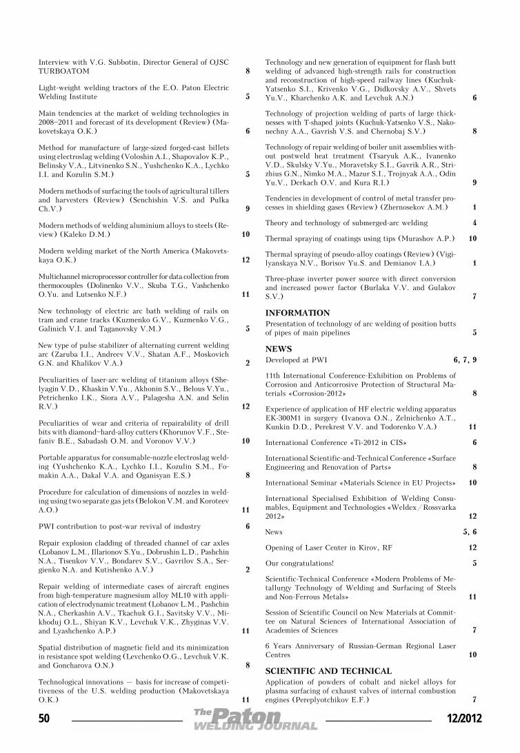
Interview with V.G. Subbotin, Director General of OJSCTURBOATOM 8
Light-weight welding tractors of the E.O. Paton ElectricWelding Institute 5
Main tendencies at the market of welding technologies in2008—2011 and forecast of its development (Review) (Ma-kovetskaya O.K.) 6
Method for manufacture of large-sized forged-cast billetsusing electroslag welding (Voloshin A.I., Shapovalov K.P.,Belinsky V.A., Litvinenko S.N., Yushchenko K.A., LychkoI.I. and Kozulin S.M.) 5
Modern methods of surfacing the tools of agricultural tillersand harvesters (Review) (Senchishin V.S. and PulkaCh.V.) 9
Modern methods of welding aluminium alloys to steels (Re-view) (Kaleko D.M.) 10
Modern welding market of the North America (Makovets-kaya O.K.) 12
Multichannel microprocessor controller for data collection fromthermocouples (Dolinenko V.V., Skuba T.G., VashchenkoO.Yu. and Lutsenko N.F.) 11
New technology of electric arc bath welding of rails ontram and crane tracks (Kuzmenko G.V., Kuzmenko V.G.,Galinich V.I. and Taganovsky V.M.) 5
New type of pulse stabilizer of alternating current weldingarc (Zaruba I.I., Andreev V.V., Shatan A.F., MoskovichG.N. and Khalikov V.A.) 2
Peculiarities of laser-arc welding of titanium alloys (She-lyagin V.D., Khaskin V.Yu., Akhonin S.V., Belous V.Yu.,Petrichenko I.K., Siora A.V., Palagesha A.N. and SelinR.V.) 12
Peculiarities of wear and criteria of repairability of drillbits with diamond—hard-alloy cutters (Khorunov V.F., Ste-faniv B.E., Sabadash O.M. and Voronov V.V.) 10
Portable apparatus for consumable-nozzle electroslag weld-ing (Yushchenko K.A., Lychko I.I., Kozulin S.M., Fo-makin A.A., Dakal V.A. and Oganisyan E.S.) 8
Procedure for calculation of dimensions of nozzles in weld-ing using two separate gas jets (Belokon V.M. and KoroteevA.O.) 11
PWI contribution to post-war revival of industry 6
Repair explosion cladding of threaded channel of car axles(Lobanov L.M., Illarionov S.Yu., Dobrushin L.D., PashchinN.A., Tisenkov V.V., Bondarev S.V., Gavrilov S.A., Ser-gienko N.A. and Kutishenko A.V.) 2
Repair welding of intermediate cases of aircraft enginesfrom high-temperature magnesium alloy ML10 with appli-cation of electrodynamic treatment (Lobanov L.M., PashchinN.A., Cherkashin A.V., Tkachuk G.I., Savitsky V.V., Mi-khoduj O.L., Shiyan K.V., Levchuk V.K., Zhyginas V.V.and Lyashchenko A.P.) 11
Spatial distribution of magnetic field and its minimizationin resistance spot welding (Levchenko O.G., Levchuk V.K.and Goncharova O.N.) 8
Technological innovations – basis for increase of competi-tiveness of the U.S. welding production (MakovetskayaO.K.) 11
Technology and new generation of equipment for flash buttwelding of advanced high-strength rails for constructionand reconstruction of high-speed railway lines (Kuchuk-Yatsenko S.I., Krivenko V.G., Didkovsky A.V., ShvetsYu.V., Kharchenko A.K. and Levchuk A.N.) 6
Technology of projection welding of parts of large thick-nesses with Т-shaped joints (Kuchuk-Yatsenko V.S., Nako-nechny A.A., Gavrish V.S. and Chernobaj S.V.) 8
Technology of repair welding of boiler unit assemblies with-out postweld heat treatment (Tsaryuk A.K., IvanenkoV.D., Skulsky V.Yu., Moravetsky S.I., Gavrik A.R., Stri-zhius G.N., Nimko M.A., Mazur S.I., Trojnyak A.A., OdinYu.V., Derkach O.V. and Kura R.I.) 9
Tendencies in development of control of metal transfer pro-cesses in shielding gases (Review) (Zhernosekov A.M.) 1
Theory and technology of submerged-arc welding 4
Thermal spraying of coatings using tips (Murashov A.P.) 10
Thermal spraying of pseudo-alloy coatings (Review) (Vigi-lyanskaya N.V., Borisov Yu.S. and Demianov I.A.) 1
Three-phase inverter power source with direct conversionand increased power factor (Burlaka V.V. and GulakovS.V.) 7
INFORMATIONPresentation of technology of arc welding of position buttsof pipes of main pipelines 5
NEWSDeveloped at PWI 6, 7, 9
11th International Conference-Exhibition on Problems ofCorrosion and Anticorrosive Protection of Structural Ma-terials «Corrosion-2012» 8
Experience of application of HF electric welding apparatusEK-300M1 in surgery (Ivanova O.N., Zelnichenko A.T.,Kunkin D.D., Perekrest V.V. and Todorenko V.A.) 11
International Conference «Ti-2012 in CIS» 6
International Scientific-and-Technical Conference «SurfaceEngineering and Renovation of Parts» 8
International Seminar «Materials Science in EU Projects» 10
International Specialised Exhibition of Welding Consu-mables, Equipment and Technologies «Weldex/Rossvarka2012» 12
News 5, 6
Opening of Laser Center in Kirov, RF 12
Our congratulations! 5
Scientific-Technical Conference «Modern Problems of Me-tallurgy Technology of Welding and Surfacing of Steelsand Non-Ferrous Metals» 11
Session of Scientific Council on New Materials at Commit-tee on Natural Sciences of International Association ofAcademies of Sciences 7
6 Years Anniversary of Russian-German Regional LaserCentres 10
SCIENTIFIC AND TECHNICALApplication of powders of cobalt and nickel alloys forplasma surfacing of exhaust valves of internal combustionengines (Pereplyotchikov E.F.) 7
50 12/2012
Application of titanium alloys with submicrocrystallinestructure for reconditioning of GTE rotor parts (Ovchin-nikov A.V.) 2
Assessment of hydrogen influence on delayed fracture ofwelded joints from high-strength low-alloyed steels (Khar-bin N.N., Sleptsov O.I., Sivtsev M.N. and Vinokurov G.G.)
6
Brazing of titanium alloys by using aluminium-base filleralloys (Khorunov V.F., Voronov V.V. and MaksymovaS.V.) 11
Calculation of local stresses in welded joint zones of large-sized space structures (Kyrian V.I., Dvoretsky V.I. andMalgin M.G.) 4
Chromium-manganese consumables for welding of higher-strength steels without preheating and heat treatment(Kulik V.M., Demchenko E.L., Vasiliev D.V. and ElaginV.P.) 10
Combined diffusion process of joining bimetal elements ofheat exchange system (Khokhlova Yu.A., Fedorchuk V.E.and Khokhlov M.A.) 1
Combined laser-microplasma cladding with powders of Ni—Cr—B—Si system alloys (Borisov Yu.S., Khaskin V.Yu.,Vojnarovich S.G., Kislitsa A.N., Tunik A.Yu., Adeeva L.I.,Kuzmich-Yanchuk E.K., Bernatsky A.V. and Siora A.V.) 11
Consideration of pore formation at estimation of limitingstate in zone of pressure vessel wall thinning defect(Makhnenko V.I., Velikoivanenko E.A., Rozynka G.F. andPivtorak N.I.) 12
Department for investigations of physical-chemical pro-cesses in the welding arc is 50 years (Pokhodnya I.K.) 6
Dislocation model of hydrogen-enhanced localizing of plas-ticity in metals with bcc lattice (Ignatenko A.V., Pokhod-nya I.K., Paltsevich A.P. and Sinyuk V.S.) 3
Effect of additions of aluminium to flux-cored wire on pro-perties of high-carbon deposited metal (Krivchikov S.Yu.) 5
Effect of heat treatment on sensitivity of the HAZ metalon titanium-stabilised austenitic steel to local fracture(Poletaev Yu.V.) 7
Effect of high-temperature thermal cycling on depositedmetal of the type of heat-resistant die steels (Ryabtsev I.A.,Kondratiev I.A., Babinets A.A., Gordan G.N., Kajda T.V.and Bogajchuk I.L.) 2
Effect of palladium on structure and technological proper-ties of Ag—Cu—Zn—Ni—Mn system brazing filler alloys (Kho-runov V.F., Maksymova S.V. and Stefaniv B.V.) 9
Effect of structural-phase transformations in aluminium-lithium alloy 1460 joints on physical-mechanical properties(Markashova L.I., Ishchenko A.Ya., Kushnaryova O.S. andFedorchuk V.E.) 5
Efficiency of electrodynamic treatment of aluminium alloyAMg6 and its welded joints (Lobanov L.M., Pashchin N.A.,Cherkashin A.V., Mikhoduj O.L. and Kondratenko I.P.) 1
Efficiency of electrodynamic treatment of welded joints ofAMg6 alloy of different thickness (Lobanov L.M., PashchinN.A. and Mikhoduj O.L.) 3
Efficiency of the use of protective extension in plasma spray-ing (Murashov A.P., Grishchenko A.P., VigilyanskayaN.V., Burlachenko A.N. and Demianov I.A.) 2
Electron beam welding of thick-wall shells of aluminiumAMg6 and M40 alloys (Ternovoj E.G. and Bondarev A.A.) 4
Experimental review of the welding metallurgy of high-strength aluminium alloy 7025-T6 (Olabode M., Kah P.and Martikainen J.) 4
Experimental study and modelling of thermal-deformationprocesses occurring in welded joints on nickel superalloys(Yushchenko K.A., Romanova V.A., Balokhonov R.R.,Savchenko V.S., Chervyakov N.O. and Zvyagintseva A.V.) 10
Experimental study of the mechanism of hydrogen embrit-tlement of metals with the bcc lattice (Sinyuk V.S., Pokhod-nya I.K., Paltsevich A.P. and Ignatenko A.V.) 5
Flash-butt welding of thick-walled pipes from high-strength steels of K56 strength class (Kuchuk-YatsenkoS.I., Shvets Yu.V., Zagadarchuk V.F., Shvets V.I., Kho-menko V.I., Zhuravlyov S.I., Sudarkin A.Ya., Kolikov V.L.and Khomichenko S.A.) 5
Formation of spinel in melt of the MgO—Al2O3—SiO2—CaF2
system agglomerated welding flux and its effect on viscosityof slag (Goncharov I.A., Sokolsky V.E., Davidenko A.O.,Galinich V.I. and Mishchenko D.D.) 12
Formation of structure and properties of 316 type steel atsuccessive circumferential electroslag surfacing with liquidmetal (Polishko A.A., Medovar L.B., Saenko V.Ya., Ste-panyuk S.I., Tunik A.Yu., Klochkov I.N. and Berezin I.V.) 2
Friction welding of PIM heat-resistant steel to steel 40Kh(Zyakhor I.V. and Kuchuk-Yatsenko S.I.) 9
Growth of corrosion cracks in structural steel 10GN2MFA(Makhnenko V.I., Markashova L.I., Makhnenko O.V.,Berdnikova E.N., Shekera V.M. and Zubchenko A.S.) 8
Heat-protecting properties of thermal spray coatings con-taining quasi-crystalline alloy of the Al—Cu—Fe system(Borisova A.L., Borisov Yu.S., Astakhov E.A., MurashovA.P., Burlachenko A.N. and Tsymbalistaya T.V.) 4
Improvement of fatigue resistance of welded joints withaccumulated damage under multistage and block loading(Knysh V.V., Solovej S.A. and Kuzmenko A.Z.) 7
Improvement of reliability of main gas pipelines by usingrepeated in-pipe flaw detection (Varlamov D.P., DedeshkoV.N., Kanajkin V.A. and Steklov O.I.) 3
Increasing wear resistance of titanium by argon arc over-laying (Prilutsky V.P., Rukhansky S.B., Akhonin S.V.,Gadzyra N.F. and Davidchuk N.K.) 1
Influence of austenitizing mode on local fracture suscepti-bility of welded joints of 03Kh16N9M2 steel (PoletaevYu.V.) 3
Influence of deposited metal composition on structure and me-chanical properties of reconditioned railway wheels (Gajvoron-sky A.A., Poznyakov V.D., Markashova L.I., BerdnikovaE.N., Klapatyuk A.V., Alekseenko T.A. and ShishkevichA.S.) 8
Influence of vibration of parts on structure and propertiesof metal in surfacing (Pulka Ch.V., Shably O.N., Sen-chishin V.S., Sharyk M.V. and Gordan G.N.) 1
Influence of welding thermal cycle on structure and propertiesof microalloyed structural steels (Kostin V.A., GrigorenkoG.M., Poznyakov V.D., Zhdanov S.L., Solomijchuk T.G.,Zuber T.A. and Maksimenko A.A.) 12
Inter-influence of defects in welded joint zone at differentforce loading (Makhnenko V.I., Velikoivanenko E.A., Mile-nin A.S., Rozynka G.F. and Pivtorak N.I.) 7
12/2012 51

Investigation of factors influencing the formation of welddefects in non-vacuum electron beam welding (Reisgen U.,Schleser M., Abdurakhmanov A., Turichin G., Valdaitse-va E., Bach F.-W., Hassel T. and Beniyash A.) 2
Investigations on laser beam welding of high-manganeseaustenitic and austenitic-ferritic stainless steels (Quiroz V.,Gumenyuk A. and Rethmeier M.) 1
Laser welding of sheet stainless steel by modulated radiation(Lukashenko A.G., Melnichenko T.V. and LukashenkoD.A.) 4
Manufacture of stainless steel—aluminum transition piecesby vacuum pressure welding method (Kharchenko G.K.,Falchenko Yu.V., Fedorchuk V.E., Grigorenko S.G. andRudenko M.M.) 1
Mathematical formulation of carbon equivalent as a crite-rion for evaluation of steel weldability (Kostin V.A.) 8
Mechanism of electromagnetic degassing of liquid metal inunderwater welding (Gorobets O.Yu., Maksimov S.Yu.and Prilipko E.A.) 6
Microstructural features of fatigue damageability and meth-ods to improve the fatigue life of welded joints from 09G2Ssteel (Poznyakov V.D., Dovzhenko V.A., Kasatkin S.B.and Maksimenko A.A.) 5
Modelling of processes of heat-, mass- and electric transferin column and anode region of arc with refractory cathode(Krikent I.V., Krivtsun I.V. and Demchenko V.F.) 3
Modification by boron of deposited metal of white cast irontype (Krivchikov S.Yu.) 6
New capabilities of mechanized arc spot welding using pulseeffects (Lobanov L.M., Lebedev V.A., Maksimov S.Yu.,Timoshenko A.N., Goncharov P.V., Lendel I.V. and Klo-chko R.I.) 5
New system of filler metals for brazing of titanium alloys(Khorunov V.F. and Voronov V.V.) 8
Peculiarities of structure and mechanical heterogeneity inEB-welded joints of 1201-T alloy (Skalsky V.R., BotvinaL.R. and Lyasota I.N.) 7
Problems of stirring and melting in explosion welding (alu-minium—tantalum) (Grinberg B.A., Elkina O.A., PatselovA.M., Inozemtsev A.V., Plotnikov A.V., Volkova A.Yu.,Ivanov M.A., Rybin V.V. and Besshaposhnikov Yu.B.) 9
Residual stresses in circumferential butt joints in the maingas pipeline at long-term service in the North (Golikov N.I.and Dmitriev V.V.) 12
Risk of failure in thinning of main pipeline wall at the areaof circumferential welds in the presence of bending momentsalong the pipeline axis (Makhnenko V.I., VelikoivanenkoE.A., Rozynka G.F., Pivtorak N.I. and Olejnik O.I.) 1
Structure and properties of welded joints of steel S390(S355 J2) (Poznyakov V.D., Zhdanov S.L. and Maksi-menko A.A.) 8
Structure and properties of welded joints on titanium alloyscontaining silicon additions (Markashova L.I., AkhoninS.V., Grigorenko G.M., Kruglenko M.G., KushnaryovaA.S. and Petrichenko I.K.) 11
Structure and wear resistance of chrome-manganese depo-sited metal (Malinov V.L. and Malinov L.S.) 7
Substantiation of «leak-before-break» criterion for verticalcylindrical tanks for oil storage (Knysh V.V., BarvinkoA.Yu., Barvinko Yu.P. and Yashnik A.N.) 9
Technological peculiarities of laser welding of medium-carbon alloyed steel (Kulik V.M., Shelyagin V.D., SavitskyM.M., Elagin V.P., Siora A.V. and Shuba I.V.) 6
Thermodynamic analysis of slag melts in manufacture offused welding fluxes (Zhdanov L.A., Duchenko A.N., Gon-charov I.A., Galinich V.I., Zalevsky A.V. and OsipovN.Ya.) 11
To the mechanism of diffusion of chromium and molybde-num in the metal of welded joints of steam pipelines(Dmitrik V.V. and Syrenko T.A.) 10
Transistor power sources for electric arc welding (Review)(Lebedev A.V.) 9
Vacuum diffusion welding of γ-TiAl intermetallic alloy to12Kh18N10T steel (Kharchenko G.K., Ustinov A.I., Fal-chenko Yu.V., Petrushinets L.V., Grigorenko S.G., KostinV.A. and Gurienko V.P.) 4
Welded structures from austenitic steel of 10Kh18N10Ttype under conditions of radiation-induced swelling(Makhnenko V.I., Makhnenko O.V., Kozlitina S.S. andDzyubak L.I.) 2
Welding from one side of clad piping of nuclear powerplants (Kasatkin O.G., Tsaryuk A.K., Skulsky V.Yu., Gav-rik A.R., Moravetsky S.I., Nimko M.A., Strizhius G.N.,Terovets N.V., Byvalkevich A.I., Nemlej N.V. and KuranR.I.) 10
Index of articles for TPWJ’2012, Nos. 1—12 12
List of authors 12
52 12/2012

LIST OF AUTHORS
Abdurakhmanov A. No.2Adeeva L.I. No.11Akhonin S.V. No.1, 11, 12Alekseenko T.A. No.8Andreev V.V. No.2Artemchuk V.V. No.7Astakhov E.A. No.4
Babinets A.A. No.2Bach F.-W. No.2Bajshtruk E.N. No.2Balokhonov R.R. No.10Barvinko A.Yu. No.3, 5, 9Barvinko Yu.P. No.3, 5, 9Belenky V.Ya. No.2Belinsky V.A. No.5Belokon V.M. No.11Belous V.Yu. No.12Beniyash A. No.2Berdnikova E.N. No.8(2)Berezin I.V. No.2Bernatsky A.V. No.10, 11Besshaposhnikov Yu.B. No.9Bogajchuk I.L. No.2Bondarev A.A. No.4Bondarev S.V. No.2Borisov Yu.S. No.1(1), 4, 11Borisova A.L. No.4Botvina L.R. No.7Bovkun V.A. No.4Bulatsev A.R. No.4Burlachenko A.N. No.1, 2, 4Burlaka V.V. No.7Byvalkevich A.I. No.10
Cherkashin A.V. No.1, 11, 12Chernobaj S.V. No.8Chervyakov N.O. No.10
Dakal V.A. No.8Davidchuk N.K. No.1Davidenko A.O. No.12Dedeshko V.N. No.3Demchenko E.L. No.10Demchenko V.F. No.3Demianov I.A. No.1, 2Derkach O.V. No.9Didkovsky A.V. No.6Dmitriev V.V. No.12Dmitrik V.V. No.10Dobrushin L.D. No.2Dolinenko V.V. No.11Dovzhenko V.A. No.5Duchenko A.N. No.11Dvoretsky V.I. No.4Dzykovich V.I. No.2Dzyubak L.I. No.2
Elagin V.P. No.6, 10Elkina O.A. No.9
Falchenko Yu.V. No.1, 4Fedorchuk V.E. No.1(1), 5, 7Fedosovsky M.E. No.7Fomakin A.A. No.8
Gadzyra N.F. No.1Gajvoronsky A.A. No.8Galinich V.I. No.5, 11, 12Gavrik A.R. No.3, 9, 10Gavrilov S.A. No.2Gavrish V.S. No.8Golikov N.I. No.12Goloborodko Zh.G. No.9Golovko V.V. No.2Goncharov I.A. No.11, 12Goncharov P.V. No.5Goncharova O.N. No.8Gordan G.N. No.1, 2Gorobets O.Yu. No.6Granovskaya L.A. No.2Grigorenko G.M. No.11, 12Grigorenko S.G. No.1, 4Grinberg B.A. No.9Grinchenko E.D. No.8Grishchenko A.P. No.2Grishin N.N. No.8Gubatyuk R.S. No.3Gubenya I.P. No.12Gulakov S.V. No.7Gumenyuk A. No.1Gurienko V.P. No.4
Hassel T. No.2
Ignatenko A.V. No.3, 5Illarionov S.Yu. No.2Inozemtsev A.V. No.9Ishchenko A.Ya. No.5Ivanenko V.D. No.9Ivanov G.A. No.1Ivanov M.A. No.9Ivanova O.N. No.11
Kah P. No.4Kajda T.V. No.2Kaleko D.M. No.4, 10Kanajkin V.A. No.3Kantor A.G. No.8Karasev M.V. No.5, 7Kasatkin O.G. No.10Kasatkin S.B. No.5Khalikov V.A. No.2Kharbin N.N. No.6Kharchenko A.K. No.6Kharchenko G.K. No.1, 4Khaskin V.Yu. No.11, 12(2)
12/2012 53

Khokhlov M.A. No.1Khokhlova Yu.A. No.1Khomenko V.I. No.5Khomichenko S.A. No.5Khorunov V.F. No.8, 9, 10, 11Kislitsa A.N. No.11Kislitsyn V.M. No.11Klapatyuk A.V. No.8Klimenko S.A. No.8Klimpel A. No.3Klochko R.I. No.5Klochkov I.N. No.2Knysh V.V. No.5, 7, 9Koleda V.N. No.3Kolikov V.L. No.5Kolomijtsev E.V. No.12Kondratenko I.P. No.1, 12Kondratiev I.A. No.2Kopejkina M.Yu. No.8Kornienko A.N. No.2—6Koroteev A.O. No.11Korotkov V.A. No.5Kostin V.A. No.4, 8, 12Kozlitina S.S. No.2Kozulin S.M. No.5, 8Kravchuk L.A. No.5Krikent I.V. No.3Krivchikov S.Yu. No.5, 6Krivenko V.G. No.6Krivtsun I.V. No.3Kruglenko M.G. No.11Kuchuk-Yatsenko S.I. No.5, 6, 9Kuchuk-Yatsenko V.S. No.8Kulik V.M. No.6, 10Kunkin D.D. No.11Kura R.I. No.9Kuran R.I. No.10Kushnaryova A.S. No.11Kushnaryova O.S. No.5Kutishenko A.V. No.2Kuzmenko A.Z. No.7Kuzmenko G.V. No.5Kuzmenko O.G. No.9Kuzmenko V.G. No.5Kuzmich-Yanchuk E.K. No.11Kyrian V.I. No.4
Lankin Yu.N. No.2Lashchenko G.I. No.8Lebedev A.V. No.9Lebedev V.A. No.5Lendel I.V. No.5Levchenko O.G. No.8Levchuk A.N. No.6Levchuk V.K. No.8, 11Lipodaev V.N. No.12Litvinenko S.N. No.5Lobanov L.M. No.1, 2, 3, 5, 10, 11, 12Lukashenko A.G. No.4Lukashenko D.A. No.4Lukin E.I. No.7Lutsenko N.F. No.11Lyashchenko A.P. No.11
Lyasota I.N. No.7Lychko I.I. No.5, 8
Makarenko N.A. No.2Makhnenko O.V. No.2, 8Makhnenko V.I. No.1, 2, 7, 8, 12Makovetskaya O.K. No.6, 11, 12Maksimenko A.A. No.5, 8, 12Maksimov S.Yu. No.5, 6Maksymova S.V. No.9, 11Malgin M.G. No.4Malinov L.S. No.7Malinov V.L. No.7Manchenko A.N. No.12Markashova L.I. No.5, 8(2), 11Martikainen J. No.4Matveev I.V. No.4Matvejchuk V.A. No.7Mazur S.I. No.9Medovar L.B. No.2Melnichenko T.V. No.4Mikhoduj O.L. No.1, 3, 11, 12Mikitenko A.M. No.5Milenin A.S. No.7Mishchenko D.D. No.12Mladenov G.M. No.2Moravetsky S.I. No.8, 9, 10Moskovich G.N. No.2Murashov A.P. No.2, 4, 10
Nakonechny A.A. No.8Nazarenko O.K. No.7Nemlej N.V. No.10Nimko M.A. No.9, 10Nurkova L.I. No.8
Odin Yu.V. No.9Oganisyan E.S. No.8Olabode M. No.4Olejnik O.I. No.1Olshanskaya T.V. No.2Osadchuk S.A. No.8Osechkov P.P. No.2Osipov N.Ya. No.11Ovchinnikov A.V. No.2
Palagesha A.N. No.12Paltsevich A.P. No.3, 5Pantelejmonov E.A. No.4Pashchin N.A. No.1, 2, 3, 11, 12Paton B.E. No.4Patselov A.M. No.9Pentegov I.V. No.11Perekrest V.V. No.11Pereplyotchikov E.F. No.7Petrichenko I.K. No.11, 12Petrushinets L.V. No.4Pismenny A.A. No.3Pismenny A.S. No.3, 11Pivtorak N.I. No.1, 7, 12Plotnikov A.V. No.9Pokhodnya I.K. No.2, 3, 5, 6, 12Poleshchuk M.A. No.4Poletaev Yu.V. No.3, 7
54 12/2012

Polishko A.A. No.2Polukhin V.V. No.3Porokhonko V.B. No.10Poznyakov V.D. No.3, 5, 8(2), 12Prilipko E.A. No.6Prilutsky V.P. No.1Prokofiev A.S. No.3Proncheva V.N. No.1Protokovilov I.V. No.10Protsenko N.A. No.5Protsenko P.P. No.5Pulka Ch.V. No.1, 9
Quiroz V. No.1
Reisgen U. No.2Rethmeier M. No.1Romanova V.A. No.10Rosert R. No.7Rozynka G.F. No.1, 7, 12Rudenko M.M. No.1Rukhansky S.B. No.1Ryabtsev I.A. No.2, 7, 11Rybin V.V. No.9
Sabadash O.M. No.10Saenko V.Ya. No.2Savchenko V.S. No.10Savitsky M.M. No.6Savitsky V.V. No.11Schleser M. No.2Selin R.V. No.12Semikin V.F. No.2Senchishin V.S. No.1, 9Sergienko N.A. No.2Shably O.N. No.1Shapovalov K.P. No.2, 5Sharyk M.V. No.1Shatan A.F. No.2Shejkovsky D.A. No.11Shekera V.M. No.8Shelyagin V.D. No.6, 12Shishkevich A.S. No.8Shiyan K.V. No.11Shuba I.V. No.6Shulym V.F. No.4Shutikov A.V. No.7Shvets V.I. No.5Shvets Yu.V. No.5, 6Sineok A.G. No.3Sinyuk V.S. No.3, 5Siora A.V. No.6, 11, 12Sivtsev M.N. No.6Skalsky V.R. No.7Skuba T.G. No.11Skulsky V.Yu. No.8, 9, 10Sleptsov O.I. No.6Sokolsky V.E. No.12Solomijchuk T.G. No.12Solovej S.A. No.7
Stefaniv B.E. No.10Stefaniv B.V. No.9Steklov O.I. No.3Stemkovsky E.P. No.11Stepanyuk S.I. No.2Strizhius G.N. No.9, 10Sudarkin A.Ya. No.5Syrenko T.A. No.10
Taganovsky V.M. No.5Ternovoj E.G. No.4Terovets N.V. No.10Timoshenko A.N. No.5Tisenkov V.V. No.2Tkachuk G.I. No.11Todorenko V.A. No.11Trojnyak A.A. No.9Trushnikov D.N. No.2Tsaryuk A.K. No.8, 9, 10Tsymbalistaya T.V. No.4, 6Tunik A.Yu. No.2, 11Turichin G. No.2
Ustinov A.I. No.4
Valdaitseva E. No.2Varlamov D.P. No.3Vashchenko O.Yu. No.11Vasiliev D.V. No.10Vavilov A.V. No.8Velikoivanenko E.A. No.1, 7, 12Vigilyanskaya N.V. No.1, 2Vinokurov G.G. No.6Vojnarovich S.G. No.11Volkov V.S. No.10Volkova A.Yu. No.9Voloshin A.I. No.5Voronchuk A.P. No.1Voronov V.V. No.8, 10, 11
Yakushin B.F. No.11Yashnik A.N. No.3, 5, 9Yavdoshchin I.R. No.12Yukhimenko R.V. No.3Yushchenko K.A. No.5, 8, 10
Zagadarchuk V.F. No.5Zalevsky A.V. No.11Zaruba I.I. No.2Zelnichenko A.T. No.11Zhdanov L.A. No.11Zhdanov S.L. No.8, 12Zhernosekov A.M. No.1Zhiltsov A.V. No.12Zhudra A.P. No.1, 2Zhuravlyov S.I. No.5Zhyginas V.V. No.11Zubchenko A.S. No.8Zuber T.A. No.12Zvyagintseva A.V. No.1Zyakhor I.V. No.9, 10
12/2012 55

56 12/2012